www.australianpipelinevalve.com.au INSTALLATION, OPERATION & MAINTENANCE MANUAL CHECK VALVES SWING, TILTING DISC & PISTON API594/API6D/ BS1868/B16.34 API 6FD & ISO 10497 Firesafe Certi ed (API 6D Version)
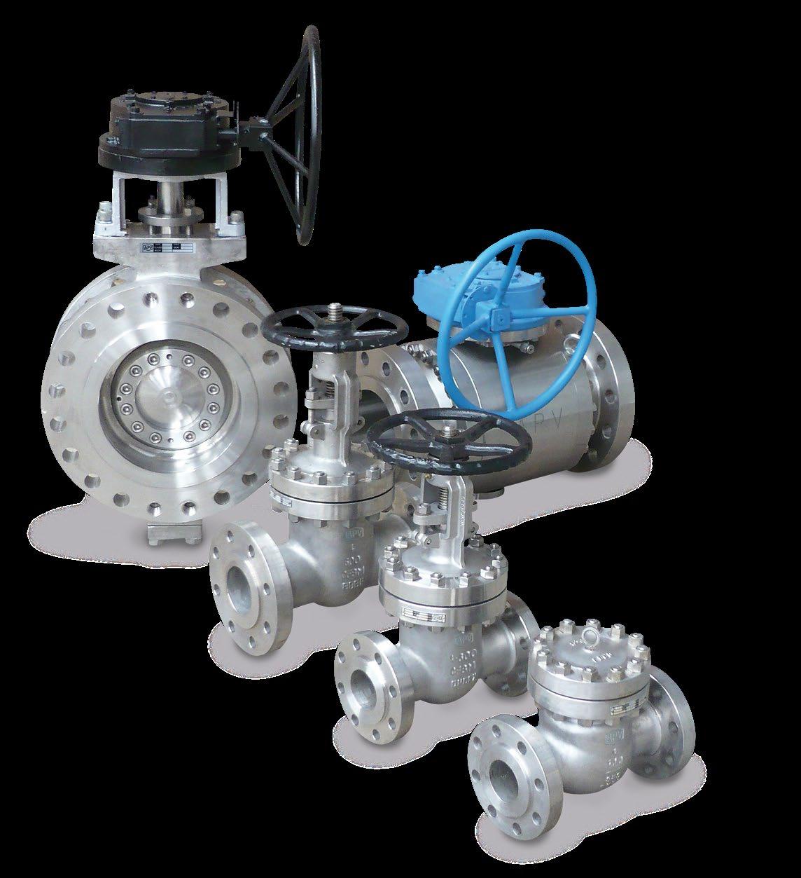
COMPLETE PRODUCT LINE
“Australian Pipeline Valve produces isolation, control and flow reversal protection products for severe and critical service media in utility, steam, pipelines, oil & gas and process industries. APV valves and pipeline products form the most competitive portfolio in the market.”

View our catalogues at www.australianpipelinevalve.com.au AUSTRALIAN PIPELINE VALVE BRAND RANGE - CATALOGUES APV FAMILY OF BRANDS RANGE - CATALOGUES
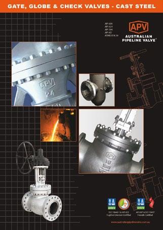
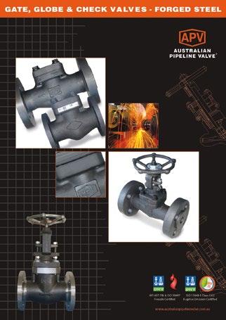
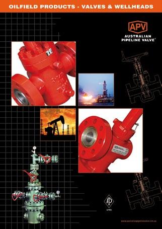
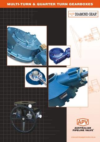
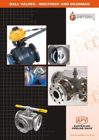
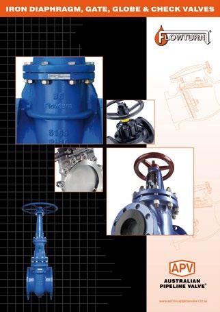
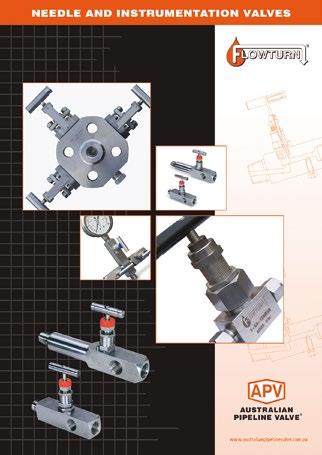
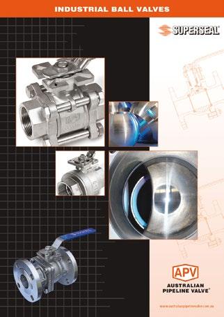
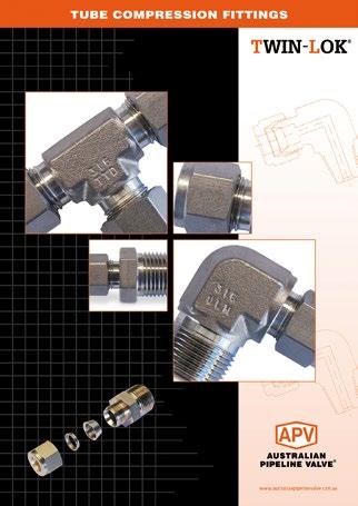
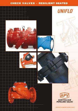
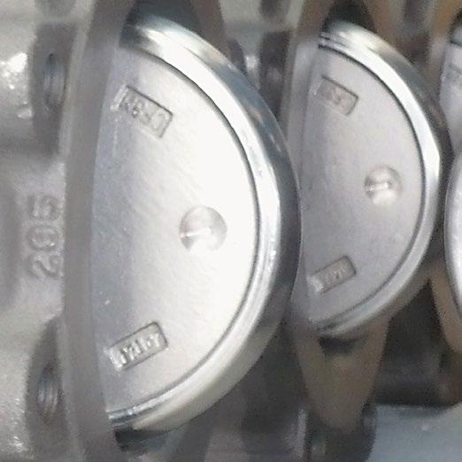
Oilfield Products Valves & Wellheads Gate, Globe & Check Valves - Forged Steel Plug Valves Lubricated, Sleeved & Lined Gate, Globe & Check Valves - Cast Steel Diamond Gear Gearboxes Flowturn Gate, Globe & Check Valves Flowturn Instrument Valves Flowturn Ball Valves Multiway & Deadman Flowturn Strainers & Sight Glasses Supercheck Wafer Check Valves Superseal Butterfly Valves Steamco Steam Valves Superseal Industrial Ball Valves TwinLok Tube Fittings Uniflo Check Valves
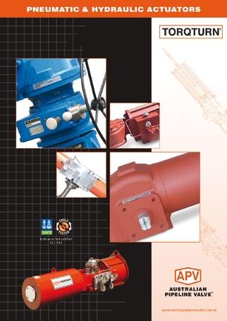
Actuators
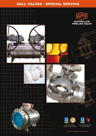
Valves Floating & Trunnion Mounted Ball Valves Floating Small Bore Ball Valves Special Service Product Brochure Contact us for your local stockist/distributor
Torqturn
Ball
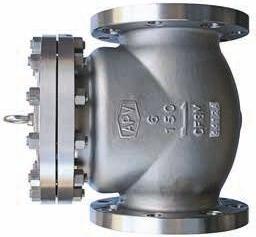
CHECK VALVES - SWING, TILTING DISC & PISTON - API594/API6D/BS1868/B16.34 Australian Pipeline Valve - Installation, Operation and Maintenance Manual 1 Introduction 2 Safety Information 3 Valve Identification 4 1.0 Installation 5-7 1.1 Installation positions 5 1.2 Preparation for installation 6 1.3 End connections 6 1.4 Post-installation procedures 7 2.0 Operation 7 3.0 Maintenance 7 4.0 Repairs 7-11 4.1 Repair instructions 8 4.2 Disassembly & gasket replacement 8 4.3 Valve internals disassembly instruction and repair 8-9 4.4 Bolted bonnet swing/lift check valve reassembly 9-11 5.0 Troubleshooting 12 6.0 Warranty and Service 12-13 6.1 Valve warranty period 12 Appendix A - Body/bonnet bolting torques 14-17 Appendix B - Figure number system 18-19 Appendix C - Exploded B.O.M. 20-25 Appendix D - Working pressure & test matrix 26 Warranty 27 INDEX
The majority of this information is common knowledge to experienced valve users. When properly installed in applications for which they were designed, Australian Pipeline Valve (APV) valves will give long reliable service under normal conditions. This instruction manual is only a guide for installation and operation on standard service and covers general maintenance and minor repairs. An APV approved valve reconditioner should be used for reconditioning and major repairs. Note
We recommend that this entire document be read prior to proceeding with any installation or repair. Australian Pipeline Valve and it’s parent company take no responsibility for damage or injury to people, property or equipment. It is the sole responsibility of the user to ensure only specially trained valve repair experts perform repairs under the supervision of a qualified supervisor.
RESPONSIBILITY FOR VALVE APPLICATION
The User is responsible for ordering the correct valves. The user is responsible for ensuring APV Valves are selected and installed in conformance with the correct pressure rating and design temperature requirements. Prior to installation, the valves and nameplates should be checked for proper identification to ensure the valve is of the proper type, material and is of a suitable pressure class and temperature rating to satisfy the applications requirements of the service application.
Do not use any valve in applications where either the pressure or temperature is higher than the allowable working values. Also valves should not be used in service media if not compatible with the valve material of construction, as this will cause chemical attacks, leakage, valve failure.
RECEIVING INSPECTION AND HANDLING
Valves should be inspected upon receipt to ensure:
- Conformance with all purchase order requirements.
- Correct type, pressure class, size, body and trim materials and end connections.
- Any damage caused during shipping.
The User is advised that specifying an incorrect valve for the application may result in injuries or property damage. Selecting the correct valve type, rating, material and connections, in conformance with the particular performance requirements is important for proper application and is the sole responsibility of the user.
CHECK VALVES - SWING, TILTING DISC & PISTON - API594/API6D/BS1868/B16.34 Australian Pipeline Valve - Installation, Operation and Maintenance Manual 2
INTRODUCTION
SAFETY INFORMATION
The following general safety information should be taken into account in addition to the specific warnings and cautions specified in this manual. They are recommended precautions that must be understood and applied during operation and maintenance of the equipment covered in this I.O.M.
To avoid injury, never attempt disassembly while there are pressures either upstream or downstream. Even when replacing gaskets, caution is necessary to avoid possible injury. Disassemble with caution in case all pressures are not relieved.
To prevent valve bending, damage, inefficient operation, or early maintenance problems, support piping on each side of the valve. Warning, certain gases and fluids could cause damage to human health, the environment or property hence the necessary safety precautions to prevent risk should be taken.
This manual provides instructions for storing, general servicing, installation and removal of check valves. APV and it’s resellers refuse any liability for damage to people, property or plant as well as loss of production and loss of income under any circumstances but especially if caused by: Incorrect installation or utilisation of the valve or if the valve installed is not fit for intended purpose. It is the sole responsibility of the user to ensure the valve type and materials are correctly specified.
DURING OPERATION TAKE INTO ACCOUNT THE FOLLOWING WARNINGS:
a- Graphite body gaskets (where applicable) are very brittle, any compacting, twisting or bending should be avoided.
b- The valve’s internal parts (disc/stem/hinge pin/seats/gaskets/seals, etc.) shall be handled with care avoiding scratches or surface damage.
c- All tools and equipment for handling the internal parts shall be soft coated, or else take care.
d- Valves can be fitted with gaskets or seals in PTFE, Buna, Viton, etc., hence high temperatures and some cleaning fluids may damage sealing components.
For all operations make reference to position number on part list of the applicable drawing.
CHECK VALVES - SWING, TILTING DISC & PISTON - API594/API6D/BS1868/B16.34 Australian Pipeline Valve - Installation, Operation and Maintenance Manual 3
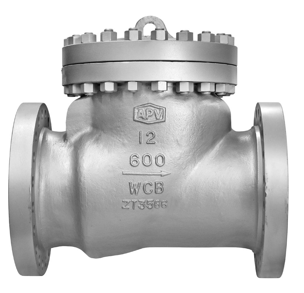
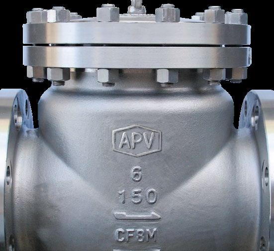
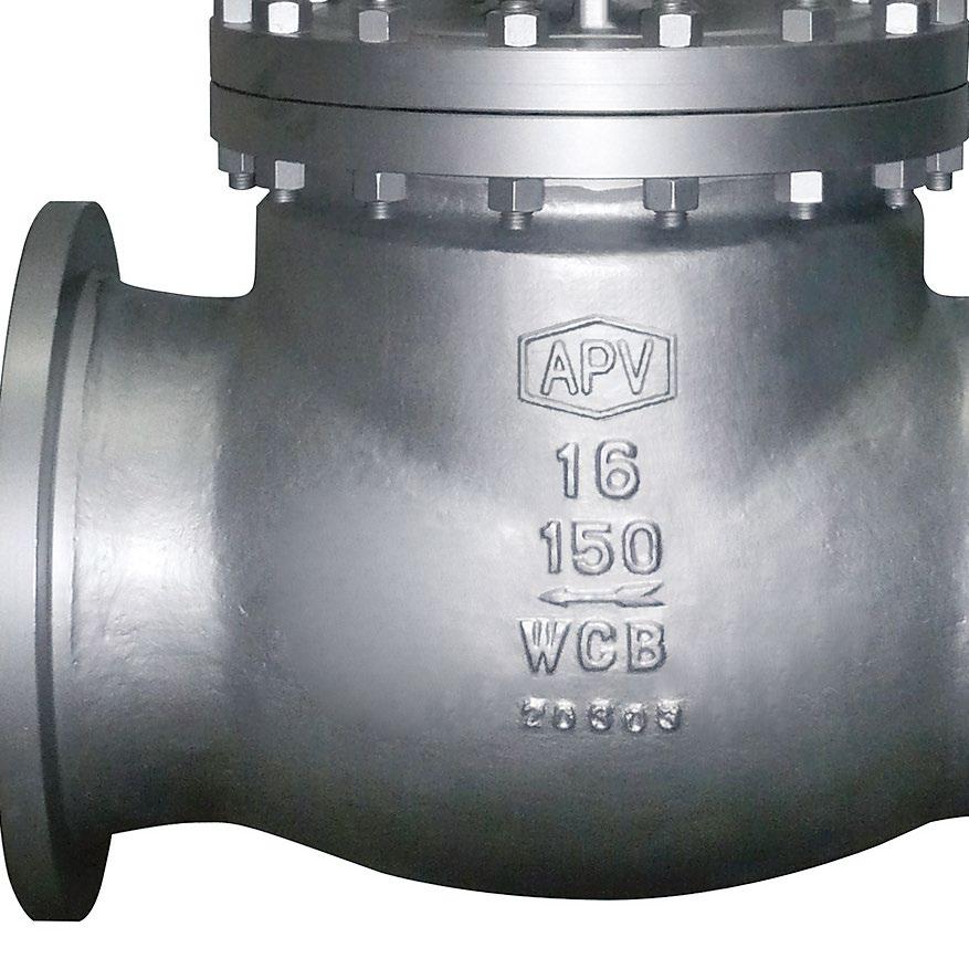
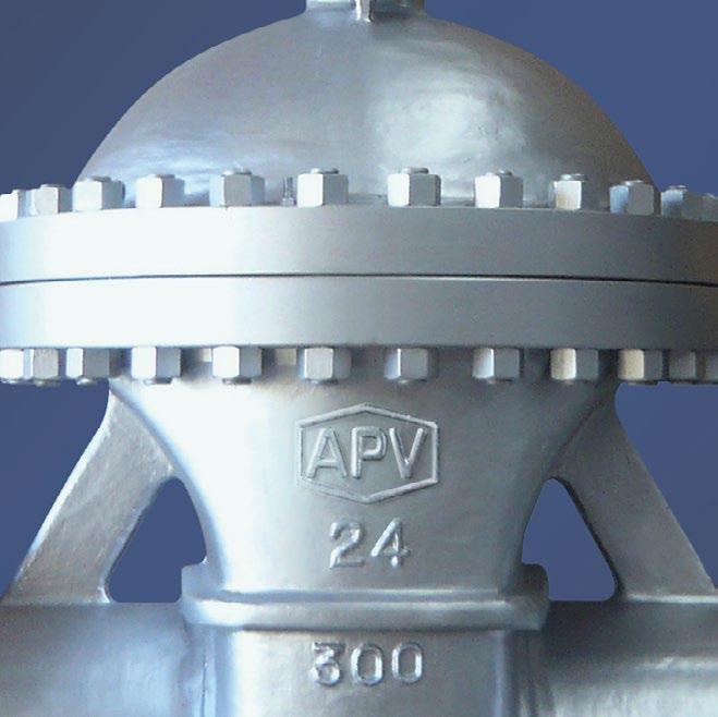
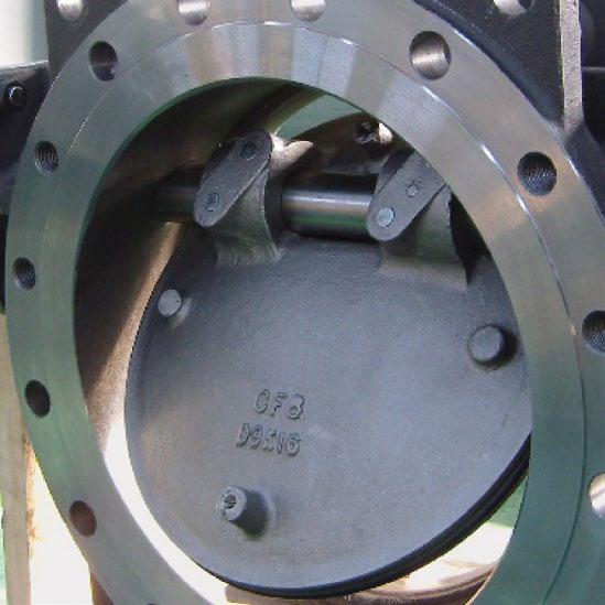
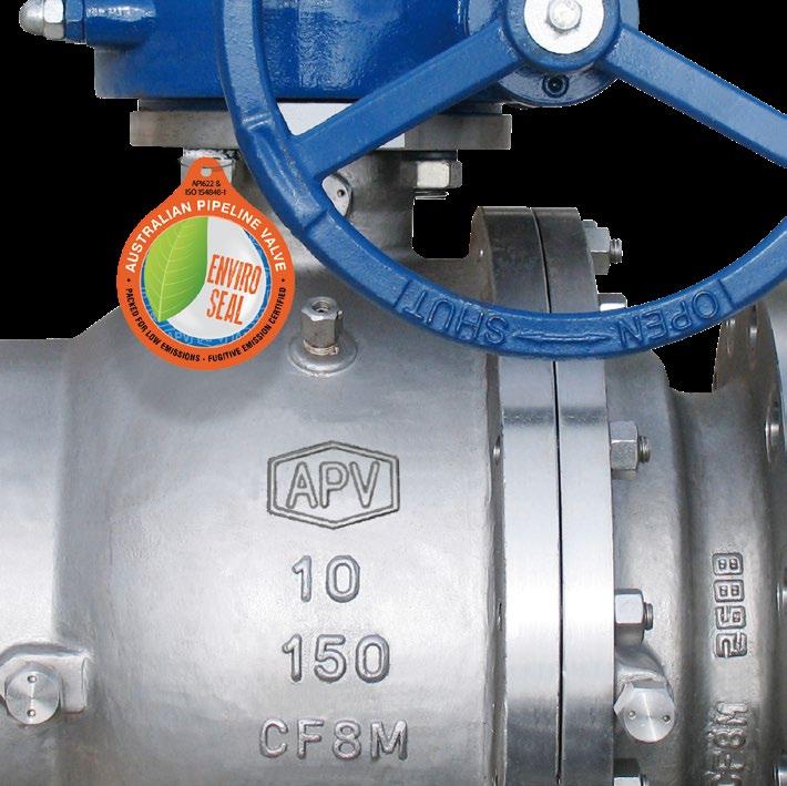
VALVE IDENTIFICATION
Each APV valve is identified with a nameplate. Below is an example.
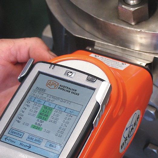
When performing any work, ordering spare parts, or requesting technical support, please refer to this tag. The serial number, the part number and numbers cast on the side of the valve body are keys to proper valve identification.
CHECK VALVES - SWING, TILTING DISC & PISTON - API594/API6D/BS1868/B16.34 Australian Pipeline Valve - Installation, Operation and Maintenance Manual 4
SIZE DISC SEAT CLASS BODY DESIGN STEM GSKT PKG CWP@38º C ASME B16.34 50NB CF8M+ST#6 316+ST#6 300 WCB API600 316L SW316 GRPFE 30 BAR 200ºC MAX 1096287-2 G360 150AP34XUN-GBW-FE 6 3 4 5 2 11 12 13 8 9 10 1 7 ITEM DESCRIPTION 1 APV valve figure number which delineats the as-built valve type, body, trim, features, packing, NACE, etc. Refer Figure Number System Appendix B 2 Shell material (e.g. body, bonnet) 3 Closure member material 4 Seat material 5 Rated pressure class as per ASME B16.34. Section 2 6 Nominal pipe size 7 Serial/batch number & stock code 8 Packing material 9 Maximum CWP @ 38ºC 10 Maximum Temperature 11 Design Standard 12 Stem material 13 Bonnet gasket material
1.0 INSTALLATION
Piping should be properly aligned and supported to reduce mechanical loading on the end connections.
1.1 INSTALLATION POSITIONS
Check valves are unidirectional and have the direction of flow indicated on the valve body. Australian Pipeline Valve swing or tilting disc check valves may be installed in horizontal lines or vertical lines where the direction of flow as indicated on the valve body is upwards.
Australian Pipeline Valve piston check valves are only for use in horizontal lines with bonnet facing up. Check valves must be fitted in horizontal pipe runs with the cover facing vertically upward. Variance to either side of the vertical axis must not exceed five (5) degrees. Swing-check valves and spring-loaded check valve designs can be positioned in vertical pipe runs with upward flow.
Check valves must not be installed in a vertical down flow pipe run or in a horizontal pipe run with the cover in the vertical down position. Always install valves in the direction indicated by the flow arrow stamped on the body. Note
Flow disturbances caused by the system components (e.g. pipe fittings, discharge of pumps, etc.) can lead to valve chatter, which can cause rapid wear of seats and trim and ultimately lea to valve malfunction. APV recommends that a sufficient distance be maintained between the check valve and any component that can cause flow disturbance as follows:
a) System components that create flow disturbance - examples are pumps, fittings and valves. When installing a check valve near system components, APV recommends a minimum of 10 pipe diameters of straight pipe between the upstream system components and the inlet of the check valve and a minimum of 2 pipe diameters of straight pipe between the downstream system components and the outlet of the check valve.
b) Pipe bends and transitions - examples are elbows, tees, branch connections and reducers. APV recommends a minimum of 6 pipe diameters of straight pipe between the upstream system component and the inlet of the check valve and a minimum of 3 pipe diameters of straight pipe between the downstream component and the outlet of the check valve.
Spring loaded piston check valves are recommended for reciprocating compressor service in which a history of noisy check valve operation has been experienced.
CHECK VALVES - SWING, TILTING DISC & PISTON - API594/API6D/BS1868/B16.34 Australian Pipeline Valve - Installation, Operation and Maintenance Manual 5
1.2 PREPARATION FOR INSTALLATION
• Remove protective end caps or plugs and inspect valve ends for damage to threads, socket weld bores or flange faces.
• Thoroughly clean adjacent piping system to remove any foreign material that could cause damage to seating surfaces during valve operation.
• Verify that the space available for installation is adequate to allow the valve to be installed.
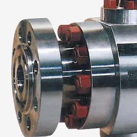
1.3 END CONNECTIONS
1.3.1 Flanged Ends
Check to see that mating flanges are dimensionally compatible with the flanges on the valve body and ensure sealing surfaces are free of debris.
Install the correct studs and nuts for the application and place the gasket between the flange facings.
Stud nuts should be tightened in an opposing criss-cross pattern in equal increments to ensure even gasket compression. See Appendix A, Table A.
1.3.2 Buttweld Ends
Clean the weld ends as necessary and weld into the line using an approved weld procedure. Make sure the pipe and valve body material given on the nameplate or valve body is compatible with the welding procedure. (Refer compatibility cross reference chart at the APV website for equivalent pipe, valve & fitting grades).
1.3.3 Valve Installation by Welding
Leave valves assembled during installation, welding and post-weld heat treatment. This will prevent the valve seat from floating or distorting during the process. After welding completion, open the valve and flush line to clean out any foreign matter.
Remove the bonnet and bonnet gasket and match mark each component during disassembly for proper reassembly.
The responsibility for welding of the valves into piping systems is that of those performing the welding. Refer to ASME B31.1, B31.3 etc. Written welding procedures covering all attributes of the process and materials to be welded shall be in accordance with Section IX of the ASME Boiler and Pressure Vessel Code and any additional requirements from the applicable piping code including any possible necessary localised post weld heat treatment depending on material specifications.
CHECK VALVES - SWING, TILTING DISC & PISTON - API594/API6D/BS1868/B16.34 Australian Pipeline Valve - Installation, Operation and Maintenance Manual 6
1.4 POST-INSTALLATION PROCEDURES
After installation, the line should be cleaned by flushing to remove any foreign material. When caustics are to be used to flush the line, additional flushing with clean water is required. The valve should be opened and closed after installation to ensure proper operating function.
With the line pressurised, check the valve end connections, body to bonnet/cover joints and external plugs for leaks.
2.0 OPERATION
Refer to Appendix A, Table C, D, E, F to ensure the Cv is as required and there is enough cracking pressure to open to disc.
The check valve operation is automatic and requires no assistance. When the flow exerts sufficient pressure against the disc to overcome the disc’s weight, the disc allows the flow to continue through the piping system. As pressure decreases, the disc lowers until it’s own weight forces it to seat. This prevents the possibility of a reversal in the flow. Piston and ball check valves should not be used in applications where rusting or rust particles are present or anticipated. Swing check valves are more tolerant for applications of this nature.
Metal seated check valves (piston, lift, tilt and swing) are not zero leak devices and will “seep” in service. This type of valve should always be backed up with an isolation valve (either gate or ball valve). Check valves are designed to prevent reverse flow. Leakage rates for check valves with metalto-metal seats are dependant on the amount of back pressure and the viscosity of the flowing medium. Soft seat check valves can offer improved leak tightness provided there is sufficient back pressure. However, soft seat check valves should not be used in gas or low back pressure liquid applications if zero leakage is desired.
3.0 MAINTENANCE
No periodic maintenance is necessary unless special external accessories are fitted.
4.0 REPAIRS
Proper safety equipment and apparel should be worn when preparing to service a valve. Observe the following general warnings:
CHECK VALVES - SWING, TILTING DISC & PISTON - API594/API6D/BS1868/B16.34 Australian Pipeline Valve - Installation, Operation and Maintenance Manual 7
• A valve is a pressurised device containing energised fluids and should be handled with care.
• Valve surface temperature may be dangerously too hot or too cold for skin contact.
• Upon disassembling, attention should be paid to the possibility of releasing dangerous and or ignitable fluids.
• Adequate ventilation should be available for service.
4.1 REPAIR INSTRUCTIONS
Due to the relatively low replacement cost of small diameter standard carbon steel valves especially under 100 NB (4”), it is usually less expensive to replace the complete valve than to have maintenance personnel effect repairs. Generally, the only viable repairs are replacement of bonnet gasket. However, see Section 4.2 and 4.3 below for further extraordinary repairs.
Always replace the bonnet gasket whenever a valve is disassembled. Gasket seating surfaces should be scraped clean (avoid radial marks). Bonnet bolts should be tightened in a diagonal pattern at several different increasing torque settings in accordance with the recommended torque value (see table Appendix A, Tables A & B).
4.2 DISASSEMBLY & GASKET REPLACEMENT
Before disassembling:
1. Check that the line is in a complete shut down phase, then remove the valve from pipeline.
2. Pre-order all necessary spare parts and joining gaskets.
3. Put identification markings on valve body, disc and bonnet. This helps to avoid mismatching of parts at the time of re-assembly.
4. If the bolts and nuts are too tight, apply deep penetrating oil and then unscrew.
Disassembly:
1. Disassemble all cover bolts and nuts.
2. For check valves, lifting lugs are generally provided. Lift up the cover utilising lifting lugs. For smaller and lower class valves the bonnet should be easy to remove without the aid of a mechanical lifting device. In both cases gently break the seal with a lever, gradually lifting the bonnet flange at intervals 360° around the bonnet.
3. Clean gasket surface areas, replace gasket and refit bonnet as detailed in 4.1 above.
4. ‘Pressure seal’ valves use a proprietary graphite gasket.
4.3 VALVE INTERNALS DISASSEMBLY INSPECTION AND REPAIR
1. Check that the (where applicable) hinge, nut and pin are in good condition and firmly connected. Replace damaged parts as necessary.
2. For swing and tilt check valves, remove the pin then lift and remove the disc hinge assembly. If
CHECK VALVES - SWING, TILTING DISC & PISTON - API594/API6D/BS1868/B16.34 Australian Pipeline Valve - Installation, Operation and Maintenance Manual 8
necessary, remove the spot weld on the disc nut, then remove the disc nut, pin, swing arm and disc in sequence. Movement should be free and not hindered by any malfunction of the hinge pin. Where disc travel is not sufficiently smooth, remove plugs or blind flanges and then remove hinge pin. Check surface for seizure or scraping marks. If marks are deeper than 1.5mm (1/16”), re-machine hinge pin and reassemble hinge pin and re-assemble. If defect depth is greater than 1.5mm (1/16”), a new hinge pin is necessary. When reassembling hinge pin, it is recommended that the disc be removed by loosening the nut. For piston/lift check valves, if there is a spring ensure it is functioning properly and is sufficiently energised. The spring should hold the disc/ball tightly against the seat no matter what position the valve is in.
3. When leakage is due to deterioration of seal surfaces caused by corrosion, erosion or foreign substances, it must be determined whether the disc or seal seat are the cause. Where special soft seat inserts are supplied, consult APV.
a) Deterioration of disc surfaces:
Swing check valves: - Disassemble disc by removing nut and washer. (Ball/Piston check valves have a free floating disc). Repair surface by grinding and relapping using a fine grade abrasive paste.
b) Deterioration of seat seal surfaces:
When seal surfaces are damaged and defects are confined to a small area but are not deeper than 0.4mm the seal surface can be relapped. For smaller sizes the recommended method is to use a cast iron strap with an outside diameter matching the valve’s raceway. If the seat surfaces cannot be relapped an APV approved repairer will decide if the surface has to be reground/re-machined or replaced. When defects are deeper than 0.4mm and found on the entire surface, re-metallising or a new seat is required. For threaded-in seats it is recommended that an anti seizure compound be used when installing the replacement seat to make threading it in the body easier.
Always be sure that the valve is de-pressurised and isolated prior to performing any maintenance work. Remove any dangerous fluids from valve before commencing maintenance.
4.4 BOLTED BONNET SWING/LIFT CHECK VALVE REASSEMBLY
a) Refer to Appendix A, Tables A & B for bolting torques.
b) To assure the valve is sealing properly, perform the required pressure testing per recognised and applicable design standards.
4.4.1
When re-assembling the valve, inspect and ensure that all components are thoroughly clean before installing into the valve body. All rust and dirt should be removed with a wire brush or emery cloth. Oil solids and grease adhered to the valve internals should be removed with approved solvents.
CHECK VALVES - SWING, TILTING DISC & PISTON - API594/API6D/BS1868/B16.34 Australian Pipeline Valve - Installation, Operation and Maintenance Manual 9
4.4.2
Apply a thing layer of light oil on the sealing surface to avoid any scratches that may occur during the assembly process.
4.2.3
Install the hinge in to the disc, install the disc nut on to the disc hinge assembly and tighten.
4.2.4
Install the hinge pin into the swing arm and hinge.
4.2.5
Install the disc/swing arm/hinge (or piston in the case of piston check) assembly into the body, ensure that bolt holes on the swing arm are aligned with valve body boss bolt holes, install the hex nuts and washers, tighten them and spot weld.
4.2.6
Install new body gasket and bonnet in to the body. Install the bolts/nuts.
4.2.7
Ensure that all studs and nuts are clean and free of rust, corrosion, burrs and previous lubricants. APV recommends installing new bolting when assembling body and bonnet connections. APV recommends coating the stud threads and surface under the nut with the molybdenum disulfide. All tightening of the bolting should be by hand; followed by the appropriate tightening sequences outlined in Appendix A, Table A Bolt Tightening Torque Chart & Appendix A Figure 2 Bolt Tightening Sequence. It is important to follow proper torque procedures. Each bolt should be torques in steps of approximately 20% of final torque. Recheck all bolting once completed.
4.2.8
Over torque can cause deformation of the body/bonnet flange causing leakage. Failure to properly follow the tightening sequence will result in the gasket not being compressed evenly, resulting in gasket leakage.
4.2.9
Never use impact devices to tighten the bolting on the body/bonnet connections. Use suitable designed mechanical devices such as hand torque wrenches for tightening and refer to Appendix A, Table A.
Torque wrenches and standard wrenches may be used in combination when performing tightening sequences.
CHECK VALVES - SWING, TILTING DISC & PISTON - API594/API6D/BS1868/B16.34 Australian Pipeline Valve - Installation, Operation and Maintenance Manual 10
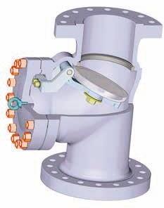
FIGURE 1
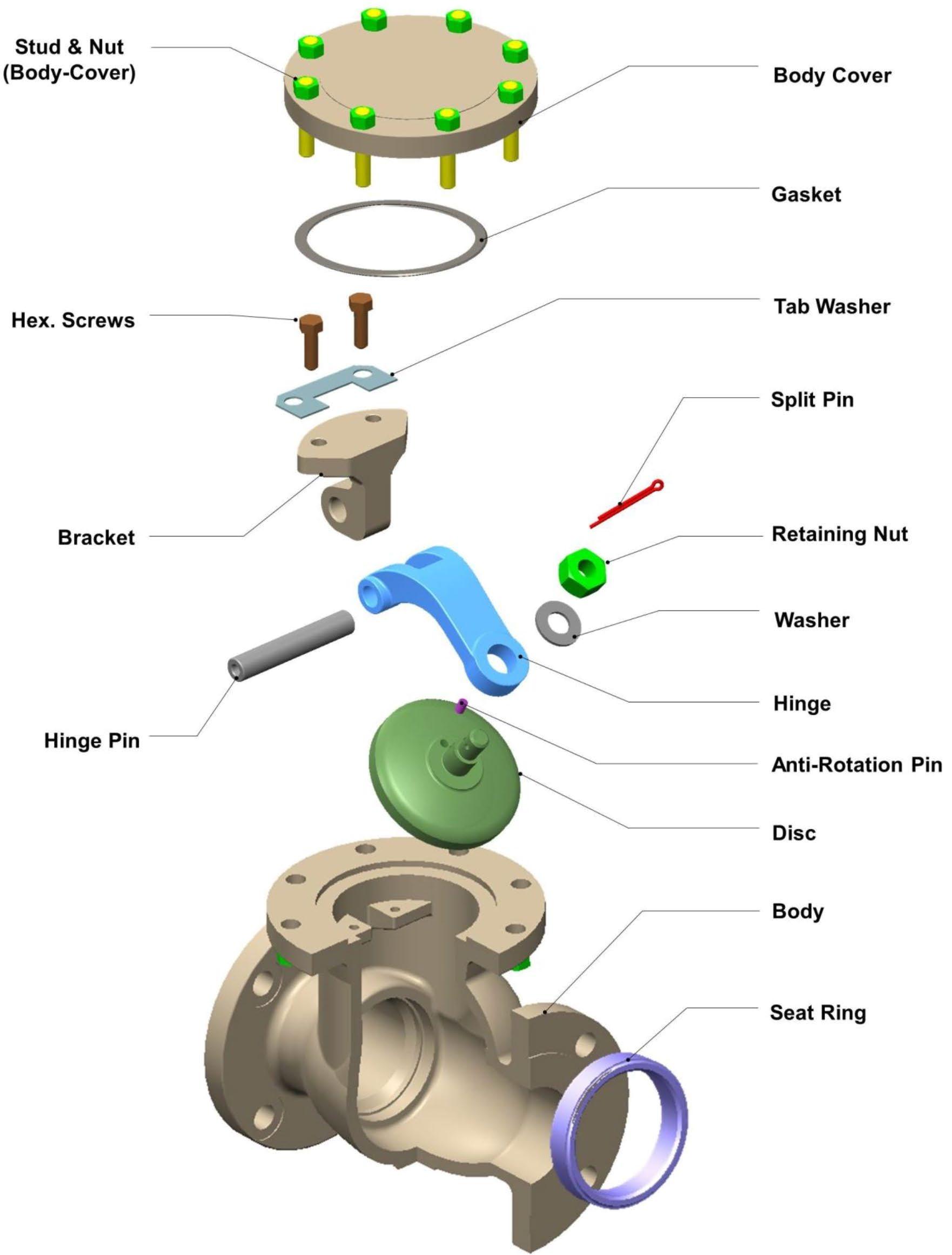
* Sample only refer to as built drawing as there are numerous designs depending on size & class. See Appendix C for examples of other designs.
CHECK VALVES - SWING, TILTING DISC & PISTON - API594/API6D/BS1868/B16.34 Australian Pipeline Valve - Installation, Operation and Maintenance Manual 11
Typical Bolted Swing Check Valve Exploded View
5.0 TROUBLESHOOTING
Dirt on the sealing surface
Leakage at sealing surface
Cannot operate normally
Bonnet gasket leakage
Valve body and bonnet both damaged and valve leaks
Disc will not operate normally
Clean the sealing surface
Sealing surface is damaged Repair the sealing surface
Dirt debris may be trapped between Hinge/ Swing Arm/Hinge Pin
Loosen flange bolt/nut
Bonnet gasket failed
Corrosion over time. Wall thickness may be below minimum required
Remove dirt or debris
Re-torque the flange bolt/nut
Replace with new gasket
Regularly check the wall thickness, replace the valve ahead of time.
Hinge Pin may be deformed and jammed Replace valve Hinge Pin
6.0 WARRANTY AND SERVICE
6.1 VALVE WARRANTY PERIOD
6.1.1
In the event the end user encounters an issue of quality, please notify APV immediately. APV reserves the right to investigate and settle all issues of quality concerns directly with the end user. Refer to APV’s standard warranty policy at the end of this I.O.M for questions or concerns regarding warranty.
6.1.2
Addressing a valve quality issue within the warranty period:
APV reserves the right to review and respond to all requests for warranty repair or replacement, prior to making any replacement or repairs by the end user.
6.1.3
APV will not be held responsible for any damage due to natural disaster, such as earthquake, hurricane, etc. during valve shipment.
6.1.4
APV must be consulted about any warranty issue before being held responsible for any repairs or valve replacement.
CHECK VALVES - SWING, TILTING DISC & PISTON - API594/API6D/BS1868/B16.34 Australian Pipeline Valve - Installation, Operation and Maintenance Manual 12
PROBLEM PROBABLE CAUSE REMEDY
WARRANTY
1. LIMITED WARRANTY: Subject to the limitations expressed herein, Seller warrants that products manufactured by Seller shall be free from defects in design, material and workmanship under normal use for a period of one (1) year from installation but in no case shall the warranty period extend longer than eighteen months from the date of sale. This warranty is void for any damage caused by misuse, abuse, neglect, acts of God, or improper installation. For the purpose of this section, “Normal Use” means in strict accordance with the installation, operation and maintenance manual. The warranty for all other products is provided by the original equipment manufacturer.
2. REMEDIES: Seller shall repair or replace, at its option, any non-conforming or otherwise defective product, upon receipt of notice from Buyer during the Manufacturer’s warranty period at no additional charge. SELLER HEREBY DISCLAIMS ALL OTHER EXPRESSED OR IMPLIED WARRANTIES, INCLUDING, WITHOUT LIMITATION, ALL IMPLIED WARRANTIES OF MERCHANTABILITY AND FITNESS OR FITNESS FOR A PARTICULAR PURPOSE.
3. LIMITATION OF LIABILITY: UNDER NO CIRCUMSTANCES SHALL EITHER PARTY BE LIABLE TO THE OTHER FOR INCIDENTAL, PUNITIVE, SPECIAL OR CONSEQUENTIAL DAMAGES OF ANY KIND.BUYER HEREBY ACKNOWLEDGES AND AGREES THAT UNDER NO CIRCUMSTANCES, AND IN NO EVENT, SHALL SELLER’S LIABILITY, IF ANY, EXCEED THE NET SALES PRICE OF THE DEFECTIVE PRODUCT(S) PURCHASED DURING THE PREVIOUS CONTRACT YEAR.
4. LABOR ALLOWANCE: Seller makes NO ADDITIONAL ALLOWANCE FOR THE LABOR OR EXPENSE OFREPAIRING OR REPLACING DEFECTIVE PRODUCTS OR WORKMANSHIP OR DAMAGE RESULTING FROM THE SAME.
5. RECOMMENDATIONS BY SELLER: Seller may assist Buyer in selection decisions by providing information regarding products that it manufacturers and those manufactured by others. However, Buyer acknowledges that Buyer ultimately chooses the product’s suitability for its particular use, as normally signified by the signature of Buyer’s technical representative. Any recommendations made by Seller concerning the use, design, application or operation of the products shall not be construed as representations or warranties, expressed or implied. Failure by Seller to make recommendations or give advice to Buyer shall not impose any liability upon Seller.
6. EXCUSED PERFORMANCE: Seller will make a good faith effort to complete delivery of the products as indicated by Seller in writing, but Seller assumes no responsibility or liability and will accept no back-charge for loss or damage due to delay or inability to deliver, caused by acts of God, war, labor difficulties, accidents, inability to obtain materials, delays of carriers, contractors or suppliers or any other causes of any kind whatever beyond the control of Seller. Under no circumstances shall Seller be liable for any special, consequential, incidental, or indirect damages, losses, or expense (whether or not based on negligence) arising directly or indirectly from delays or failure to give notice of delay.
CHECK VALVES - SWING, TILTING DISC & PISTON - API594/API6D/BS1868/B16.34 Australian Pipeline Valve - Installation, Operation and Maintenance Manual 13
APPENDIX A
INDICATIVE BONNET BOLTING (BOLTED BONNET*) TORQUE NM
* Consult APV for pressure seal bonnet
Note:
(1) Torque tolerance ±10%.
(2) For temperatures above 750°F (400°C) use 75% of the torque values. In high temperature services, there is a possibility of creep in the bonnet studs. Regular checking of the bonnet - studs for tightness, would help prevent leakage through the bonnet gasket.
(3) Above torque values are with the bolts lubricated.
(4) Values above are based on 30,000 psi (206.85 Mpa) bolting stress and lubricated with heavy graphite and oil mixture or a copper based anti-seize grease.
(5) Do not exceed by more than 25% of values stated when emergency torquing is required.
(6) All bolts shall be torqued in the pattern as shown in Figure 2 on next page to ensure uniform gasket loading.
(7) Optimum torque can vary depending on type of body gasket but do not increase torque more than 10% above those shown.
(8) Consult us for other bolt material.
(9) Most B8M and B8 bolts are class 1 so do not assume class 2 unless you are sure.
Note
For ‘pressure seal’ bonnet consult APV for torques (where bolting is applicable). Bolt tensions shown must be decreased by 25% when other or no lubrication used. Non lubricated bolts can have an efficiency of less than 50% the torque of values stated. Indicative torques are shown only, different body gasket systems, different sizes & classes, etc., will have different torque requirements. Furthermore, other stud grades can have much lower torques depending if class 1 or class 2 and or above variables.
CHECK VALVES - SWING, TILTING DISC & PISTON - API594/API6D/BS1868/B16.34 Australian Pipeline Valve - Installation, Operation and Maintenance Manual 14
TABLE A STUD SIZE inch-TPI Bolting Material B7/B7M/B16/L7/L7M/ L43/660 Cl.A/UNS N07718/UNS 09925 B8 Cl.2/B8C Cl.2/B8M Cl.2/B8T Cl.2/XM-19 UNS N06625 Gr 1 1/4-20 UNC 7 7 5 5/16-18 UNC 15 15 10 3/8-16 UNC 25 25 15 7/16-14 UNC 40 40 25 1/2-13 UNC 60 60 40 9/16-12 UNC 90 90 60 5/8-11 UNC 120 120 80 3/4-10 UNC 215 215 145 7/8-9 UNC 345 315 230 1-8 UNC 520 475 345 1.1/8-8 UN 725 625 510 1.1/4-8 UN 1000 880 715 1.3/8-8 UN 1460 975 975 1.1/2-8 UN 1925 1285 1285 1.5/8-8 UN 2480 1655 1655 1.3/4-8 UN 3140 2090 2090
APPENDIX A - CONT.
BOLT TIGHTENING SEQUENCE EXAMPLE
FIGURE 2
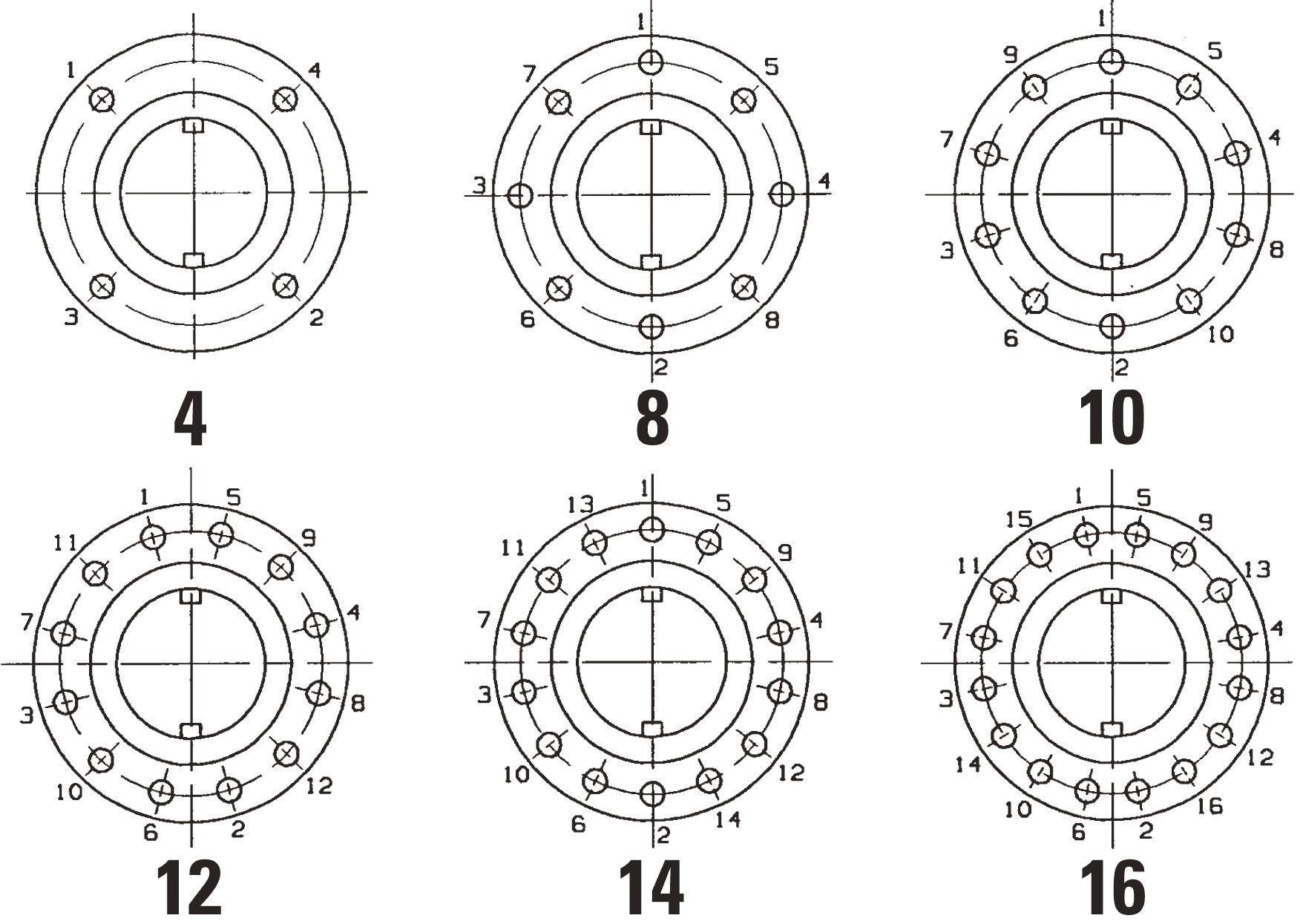
TABLE B
When torque wrenches are not available or suitable, the use of standard wrenches and guidelines will apply to avoid over torque or damage to the valve. (Never use impact wrench)
CHECK VALVES - SWING, TILTING DISC & PISTON - API594/API6D/BS1868/B16.34 Australian Pipeline Valve - Installation, Operation and Maintenance Manual 15
UNC BOLT SIZE LENGTH OF WRENCH 3/8” 125mm (5”) 1/2” 150mm (6”) 9/16” 225mm (9”) 5/8” 300mm (12”) 3/4” 450mm (18”) 7/8” 600mm (24”) 1” 750mm (30”) 1 1/8” 900mm (36”) 1 1/4” 1050mm (42”)
CHECK VALVES - SWING, TILTING DISC & PISTON - API594/API6D/BS1868/B16.34 Australian Pipeline Valve - Installation, Operation and Maintenance Manual 16
C Cv Value for API 594/BS 1868 Swing Check Valve Size Units (gal/min)/(lbf/in2)0.5 mm inch 150LB 300LB 600LB 900LB 1500LB 2500LB 50 2 123.9 123.9 123.9 105.0 105.0 68.1 80 3 281.8 281.8 281.8 259.3 239.4 159.6 100 4 524.1 524.1 521.4 482.7 425.5 267.1 150 6 1234.6 1234.6 1234.6 1140.7 988.2 259.3 200 8 2281.5 2281.5 2213.5 2021.0 1751.1 1180.7 250 10 3573.7 3573.7 3404.3 3137.6 2729.9 300 12 5340.4 5340.4 5104.7 4569.4 3975.9 350 14 6511.0 6511.0 6142.9 5565.3 4794.4 400 16 8624.9 8624.9 8068.6 7268.9 6267.6 450 18 11472.8 11155.6 9575.4 500 20 14304.0 13964.2 12884.7
24 20866.1 20419.8 18682.8
30 33735.6 TABLE D Cracking Pressure for API 594/BS 1868 Swing Check Valve Size Units kPa (Psi) mm inch 150LB 300LB 600LB 900LB 1500LB 2500LB 50 2 1.93 (0.28) 2.00 (0.29) 2.20 (0.32) 4.75 (0.69) 5.10 (0.74) 7.10 (1.03) 80 3 2.27 (0.33) 2.48 (0.36) 2.82 (0.41) 3.17 (0.46) 4.34 (0.63) 8.54 (1.24) 100 4 1.79 (0.26) 1.93 (0.28) 1.72 (0.25) 2.76 (0.40) 4.48 (0.65) 7.10 (1.03) 150 6 1.24 (0.18) 1.17 (0.17) 2.07 (0.30) 3.58 (0.52) 3.72 (0.54) 8.54 (1.24) 200 8 1.52 (0.22) 1.52 (0.22) 2.27 (0.33) 3.93 (0.57) 4.82 (0.70) 10.54 (1.53) 250 10 1.31 (0.19) 1.31 (0.19) 2.14 (0.31) 4.13 (0.60) 5.79 (0.84) 300 12 1.45 (0.21) 1.45 (0.21) 2.82 (0.41) 4.00 (0.58) 6.13 (0.89) 350 14 2.07 (0.30) 2.14 (0.31) 3.31 (0.48) 3.86 (0.56) 9.78 (1.42) 400 16 1.72 (0.25) 1.72 (0.25) 3.24 (0.47) 4.96 (0.72) 9.65 (1.40) 450 18 1.65 (0.24) 2.14 (0.31) 3.58 (0.52) 5.51 (0.80) 500 20 1.86 (0.27) 2.27 (0.33) 600 24 1.79 (0.26) 2.89 (0.42)
APPENDIX A - CONT. TABLE
600
750
APPENDIX A - CONT.
CHECK VALVES - SWING, TILTING DISC & PISTON - API594/API6D/BS1868/B16.34 Australian Pipeline Valve - Installation, Operation and Maintenance Manual 17
TABLE E Cv Value for API 6D Swing Check Valve Size Units (gal/min)/(lbf/in2)0.5 mm inch 150LB 300LB 600LB 900LB 1500LB 2500LB 50 2 124 124 124 124 124 101 80 3 282 282 282 282 282 200 100 4 523 523 523 523 523 398 150 6 1236 1236 1236 1236 1141 947 200 8 2283 2283 2283 2283 2085 1815 250 10 3574 3574 3574 3574 3217 2804 300 12 5347 5347 5347 5347 4801 4098 350 14 6528 6528 6528 6034 5813 4969 400 16 8609 8609 8609 8084 7533 6451 450 18 11478 11478 11478 10807 9960 8459 500 20 14307 14307 14307 13386 12441 10605 600 24 20898 20898 20898 19576 17968 TABLE F Cracking Pressure for API 6D Swing Check Valve Size Units kPa (Psi) mm inch 150LB 300LB 600LB 900LB 1500LB 2500LB 50 2 2.55 (0.37) 2.55 (0.37) 2.55 (0.37) 2.27 (0.33) 3.79 (0.55) 4.82 (0.70) 80 3 1.72 (0.25) 1.72 (0.25) 2.69 (0.39) 2.00 (0.29) 2.82 (0.41) 5.37 (0.78) 100 4 1.72 (0.25) 1.72 (0.25) 1.45 (0.21) 2.55 (0.37) 2.82 (0.41) 3.58 (0.52) 150 6 0.96 (0.14) 0.96 (0.14) 1.58 (0.23) 2.89 (0.42) 2.82 (0.41) 4.82 (0.70) 200 8 1.31 (0.19) 1.31 (0.19) 1.86 (0.27) 3.24 (0.47) 3.86 (0.56) 250 10 1.10 (0.16) 1.10 (0.16) 1.65 0.24) 3.17 (0.46) 4.48 (0.65) 300 12 1.10 (0.16) 1.10 (0.16) 2.34 (0.34) 2.27 (0.33) 4.48 (0.65) 350 14 1.65 (0.24) 1.38 (0.20) 2.48 (0.36) 400 16 1.38 (0.20) 1.72 (0.25) 2.76 (0.40) 450 18 1.72 (0.25) 2.55 (0.37) 2.55 (0.37) 500 20 2.55 (0.37) 1.72 (0.25) 2.69 (0.39) 600 24 1.72 (0.25)
APPENDIX B
FIGURE NUMBER SYSTEM
EXAMPLE 150AP125QTISN-9PBWG-FA
Bonnet gasket: Blank Standard:- SS + GRP (BB), Pressure Seal Ring (PSB).
N/A:- (WB). A SS + PTFE B S31803 Spiral C PTFE
D SS + PTFE + GRP E Ring L Live Loaded Z Special
Stem packing: Blank Standard:- Graphite. N/A:- (Check Valves)
L Graphite + PTFE T PTFE F Fugitive Emission GRP
I Fugitive Emission PTFE J Special
Denotes special suffix - Packing/Gasket
Operator: Blank Handwheel or N/A A Actuator
G Gear H Hammer Blow Handwheel
End connection: Blank RF (B16.5) BA RF B16.47A (MSS SP44)
BB RF B16.47B (API 605) RJ RTJ BW Buttweld FF Flat Face
SP is special drilling UD Undrilled UM Unmachined for RF/RJ
Bonnet: Blank Bolted C Cryogenic H Pillar & Bridge L Low Temperature
P Pressure Seal S Bellows Sealed W Welded
Body material: - see page 5. (WCB is Blank)
Denotes special suffix - Body/Bonnet/Ends/Operator
Blank Non NACE N NACE
Blank Standard Configuration (Example Solid Wedge) A S Bend Globe D Globe-Stop Check
DG Globe - Stop Check Guided F Flexible Disc Gate J Slab Gate K Expanding Gate L Lever (Swing Check)
P Full Opening Swing Check (API 6D) Q Full Opening Piston Check (API 6D) R Right Angle S Parallel Slide
Y Inclined Bonnet Z c/w Spring
Denotes trim - Code & Modifier (see below)
Basic identifier number denoting valve class and valve type (As shown in catalogue)
Valve Size
TRIM CODES
CHECK VALVES - SWING, TILTING DISC & PISTON - API594/API6D/BS1868/B16.34 Australian Pipeline Valve - Installation, Operation and Maintenance Manual 18
F - G BW PL 9 N - S QTI AP125 150 A
(1) Add modifier below if applicable. (2) As per trim code above. (3) Or Integral as per body. (4) API trim code #1 only (5) Geothermal trim. (6) Can be dual certified 316/316L. BODY SEAT SURFACE DISC SURFACE STEM BACK SEAT (STUFFING BOX) TRIM CODE (1) B Bronze Bronze Bronze Bronze C AL-Bronze AL-Bronze AL-Bronze AL-Bronze D Monel(1) Monel(1) Monel Monel E F51(1) F51(1) F51 F51 G F55(1) F55(1) F55 F55 H Hastelloy B(1) Hastelloy B(1) Hastelloy B Hastelloy B L F316(1)(6) F316(1)(6) F316(6) F316(6) M F316L(1) F316L(1) F316L F316L N Alloy 20(1) Alloy 20(1) Alloy 20 Alloy 20 P F304(1) F304(1) F304 F304 Q F304L(1) F304L(1) F304L F304L R Alloy 625(1) Alloy 625(1) Alloy 625 Alloy 625 V F53(1) F53(1) F53 F53 W F347(1) F347(1) F347 F347 Blank F6a/F6/410 F6a/F6/410 F6a/F6/410 F6a/F6/410 Z Special(1) Special(1) Special Special MODIFIER EN ENP ENP (2) (2) (3) GE(5) Stellite #6 Stellite #12 17-4 PH Stellite #6 I - - 17-4 PHM - - MonelT +PTFE Seat - -U Stellite Stellite (2) (2) (3) X (4) (4) (4) (4) XU Stellite (2) (2) (2) (3) Z - - Special -
APPENDIX B - CONT.
CHECK VALVES - SWING, TILTING DISC & PISTON - API594/API6D/BS1868/B16.34 Australian Pipeline Valve - Installation, Operation and Maintenance Manual 19
FIGURE NUMBER SYSTEM - BODY MATERIAL CODE • BODY/BONNET MATERIALS Suffix ASTM Spec. Material None A216 WCB Carbon Steel 1 A216 WCC Carbon Steel 1A A217 WC1 Carbon Moly 1/2% Mo 2 A352 LCC Low Carbon Steel 2B A352 LCB Low Carbon Steel 4 A351 CF3M Stainless with Molybdenum (low carbon) 5 A217 Gr. C5 5% Cr, 1/2% Mo 6 A217 Gr. WC6 1-1/4% Cr, 1/2% Mo 7 A217 Gr. WC9 2-1/4% CR, 1% Mo 8 A351 CF8 Stainless 18% Cr, 8% Ni 8A A351 CF3 Stainless 18% Cr, 8% Ni (low carbon) 8D A351 CF8C Stainless 18% Cr, 10% Ni & Cb 8M A351 CF8M Stainless with Molybdenum 9 A217 Gr. C12 Chrome Moly 9% Cr, 1% Mo 10 A352 LC1 Carbon Moly 1/2% Mo 11 A352 LC3 Low Carbon Steel (-101oC) 13 A351-CN7M Alloy 20 14 A890/A995-4A/CD3MN Duplex (F51)
A995-6A/CD3MWCuN Super Duplex (F55)
Bronze Bronze B62/LG2/B148 20 AL-Bronze Aluminium Bronze 21 A995-5A/CE3MN Super Duplex (F53) 22 A296 M-35 Monel 23 A296 CW-12M Hastelloy C 24 A484 CU-5M CUC Inconel 825 25 A494 CY40 Inconel 600 26 A494 CW6MC Inconel 625 27 B367 GR.C2 Titanium (F2) 28 B367 GR.C3 Titanium (F3) 29 A358 LC4 Low Temp. 4-1/2% 30 A358 LC9 9% Nickel Steel 31 A358 CA6NM 18-1/2% Chromium, 32 A217 WC4 Nickel Chromium 33 A217 WC5 Nickel Chromium 34 A217 WC11 Chromium Molybdenum 35 A217 C12 Chromium Molybdenum 36 A217 C12A Chromium Molybdenum 37 A217 CA15 Chromium Steel 0 SPECIAL
15
19
CHECK
APPENDIX C
EXPLODED B.O.M. SWING CHECK
-
CF8M+STL#6
A351
ASTM
Mpa
Psi
NOTES 1 2 3 4 5 6 7 8 9 10 BODY DISC NUT SPLIT PIN WASHER DISC ARM SEAT SHAFT SUPPORT FORK BOLT
www.australianpipelinevalve.com.au
ºF ASME B16.34 Mpa
BACKSEAT B16.34 BODY TEMPERATURE MEDIUM Water, Oil, Gas ºC ASME B16.34
B.T. S.Q. C.C.
DWG FRM 397 -
APPROVED CHECKED DRAWN 397 00 MATERIAL
ASTM A351 CF8M ASTM A194 8M ASTM A276 316 ASTM A276 316 ASTM A351 CF8M INTEGRAL ASTM A276 316 ASTM A351 CF8M ASTM A193 B8M
Psi Mpa Psi Mpa Psi 2.9 425 2.2 325 11 12 13 14 15
(5 ) (2)
(1)
WHEN Dimensions in millimeters DIMENSIONS (MM) & WEIGHT (KG) DN
APV
CL 150 ASME B16.34 & BS1868 ASME B16.34 ASME B16.10 RFSF 3.2 ~ 6.3Ra ASME B16.5 API 598/ISO 5208 MSS SP-25 PICKLED & PASSIVATED BODY FULL PORT, LARGE OPEN FLAPPER ≥ 100NB API #12 NACE MR-01-75 & MR-01-03 (ISO 15156) LOST WAX INVESTMENT CAST
RATING DESIGN & MFG. PRESS-TEMP RATING FACE TO FACE DIM. END CONNECTION END
&
t
H n-d
C
O
i
L
g Inch
24.3 222.0 8-19
Weight 100 292
24.0 304.5 8-22
102
40 125 330
230 190.5 157 4”
Example only, refer to as-built drawing.
26.0 350.0 8-22
127
66 150 356
254 216.0 186 5”
29.0 407.0 8-22
152
78T 200 495
279 241.5 216 6”
31.0 463.0 12-25
200
137 250 622
343 298.5 270 8”
290
32.0 538.0 12-25
250
207 300 698
406 362.0 324 10”
483 432.0 381 12”
300
API594/API6D/BS1868/B16.34 Australian Pipeline Valve - Installation, Operation and Maintenance Manual 20
VALVES - SWING, TILTING DISC & PISTON -
15 10 A 9 4 9 10 7 H±5 O C g i 1.6 n-d L t 6 5 3 2 1 12 14 16 11 8 13 Spot weld (5mm) both sides A BILL OF MATERIALS
Check Valve, Swing, Model 100~300AP147LXUN-8M, NPS 4”~12” (DN100~DN300) Class 150, RF, BB NO.
ORDER No/ DWG No REV. PART NAME
-
(2) - - (4) (6) (7) PICKLED & PASSIVATED (3) (5) - (5)
Australian Pipeline Valve
DIMENSION TEST
INSPECTION MARKING
OTHER REQ. PORT SIZE TRIM NOTES OTHER
TEST PRESSURE SHELL HYDRO SEAT HYDRO SEAT AIR
Ra ≤ 0.32 µ m IN ACCORDANCE WITH API 594 (3) THE BODY SEAT RING IS INSTALLED ON A 3 ANGLE. THIS ALLOWS CHECK VALVE TO CLOSE EVEN
GASKET (ENCAPSULATED) BOLT NUT BONNET LIFTING EYELET INSTALLED IN HORIZONTAL PIPE RUN WITH NO PRESSURE (4) THICKNESS OF FACING MATERIAL ≥ 1.6MM AS PER API 594 (5) DISC & SEAT LAPPED TO Ra 0.6
316+FLEXIBLE GRAPHITE ASTM A193 B8M ASTM A194 8M ASTM A351 CF8M CARBON STEEL 0.8 µ m (6) THICKNESS OF FACING MATERIAL ≥ 1.6MM AS PER API (7) STELLITE HARDNESS 36
PICKLED & PASSIVATED (1) ZINC PLATED - SPIRAL WOUND45 HRC (331
≥ 125NB 427 HB) 16 LABLE
STEM SMOOTHNESS AISI 316
APPENDIX C - CONT.
EXPLODED
-
SS
16 COTTER PIN
(1) DUAL CERTIFIED ASTM A216 WCB (2) SMOOTHNESS Ra ≤ 3.2 µ m IN ACCORANDANCE WITH API 594 & API 6D (3) .35% MAXIMUM CARBON EQUIVALENT (4) DUAL LABLED & CAST APV & FZV. CE/PED LABLED. API MONOGRAMMED (5) THE BODY SEAT RING IS INSTALLED ON A 3 ANGLE. THIS ALLOWS CHECK VALVE TO CLOSE EVEN WHEN INSTALLED IN HORIZONTAL PIPE RUN WITH NO PRESSURE (6) THICKNESS OF FACING MATERIAL ≥ 1.6MM AS PER API REQUIREMENTS (7) DISC & SEAT LAPPED TO Ra 0.2
45 HRC (331
0.4 µ m SUPERIOR TO OTHER MANUFACTURER S TOLERANCES (8) STELLITE HARDNESS 36
DIM. Psi Mpa
RATING
RATING Psi
DIMENSION Mpa
TO Mpa
CONNECTION END Psi
CL 1500 API 6D DUAL CONFORMS API 594 ASME B16.34 ANSI B16.10 SCHEDULE 160 BUTTWELD ASME B16.25 API6D LEAKAGE ISO 5208-D * MSS SP-25 PAINT PPF07.002 CORROSION ALLOWANCE 4.0MM. INVESTMENT CAST FULL PORT FULL OPENINGPIGGABLE B
427 HB) *SUPERIOR SHUT OFF THAN API 598. (EQUIVALENT API 598 GATE VALVE LEAKAGE RATE IN DROPS/MINUTE)
#5 NACE MR-01-75 & MR-01-03 (ISO 15156). API 6D MONOGRAMMED A
R O VED CH E CKED DR A WN 138 00
1035 ASTM A276 304 SS APP
ORDER N o / D W G N o RE V .
INSPECTION MARKING L
& DN
TEST Psi 38.76 5625 28.42 4125 Inch
(MM) &
95
Q1/ API 6D LICENSED MANUFACTURER, DYE PENETRANT TEST ON BEVELLED ENDS MSS-SP93 TEST PRESSURE SHELL HYDRO SEAT HYDRO SEAT AIR BACKSEAT B16.34 BODY H
160
297
91
66.64
OTHER REQ. PORT SIZE TRIM NOTES OTHER D
76
470
80
SCH Weight 3”
CHECK VALVES - SWING, TILTING DISC & PISTON - API594/API6D/BS1868/B16.34 Australian Pipeline Valve - Installation, Operation and Maintenance Manual 21
B.O.M. SWING CHECK
refer to as-built drawing. www.australianpipelinevalve.com.au API 6FD & ISO 10497 Firesafe Certi ed API 6D 1473 API Q1 2345 SHELL TAMAP 2 STAR CHEVRON APPROVED BP APPROVED SIL 2 & 3 15 14 16 13 12 11 10 9 8 7 6 5 4 3 SPOT WELDED D A B H 2 1 BIL L OF M A TERIALS Dimensions in millimeters NO. P ART NAME M A TERIAL NOTES 1 2 3 4 5 6 7 8 9 10 11 12 13 14 15 BODY SEAT DISC DISC ARM NUT SHAFT SUPPORT FORK STUD NUT BOLT RING GASKET BONNET LIFTING RING NAMEPLATE RIVET ASTM A216 WCC ASTM A105+STL6 ASTM A105+STL6 ASTM A216 WCC ASTM A194 2HM ASTM A182 F6A ASTM A216 WCC ASTM A193 B7M ASTM A194 2HM ASTM A193 B7M ASTM A182 316 ASTM A105 AISI
DIMENSIONS
WEIGHT
APV DWG FRM
ZINC PLATED (4) - - - - (1) - - (2) (1) (3) (6) (7) (8) (5) (6) (7) (8)
Example only,
(KG)
138
-
Check Valve, Swing, Model 80APP199UN1-BW, API6D NPS 3” (DN80) Class 1500, BW, BB
PRESS-TEMP
FACE
FACE
END
API
Australian Pipeline Valve API
B.T. S.Q. C.C. TEMPERATURE MEDIUM Water, Oil, Gas ºC -29 TO 425
DESIGN & MFG. ºF -20 TO 800 Mpa
APPENDIX C - CONT.
EXPLODED B.O.M. SWING CHECK
SPIRAL WOUND
316 ASTM
ASTM
BOLT SPRING WASHER GASKET (ENCAPSULATED) BONNET
DIMENSIONS (MM) & WEIGHT (KG)
OTHER
R O VED
APP
Check Valve, Swing, Model 250~450AP147XUPN, NPS 10”~18” (DN250~DN450)
E CKED
VALVES - SWING, TILTING DISC & PISTON - API594/API6D/BS1868/B16.34 Australian Pipeline Valve - Installation, Operation and Maintenance Manual 22
CHECK
www.australianpipelinevalve.com.au API 6FD & ISO 10497 Firesafe Certi ed 1 2 3 4 5 6 7 8 9 10 11 12 13 14 15 16 H± 5 L ±3.0 t n-d 1.6 O C g i 17 18 AA A A 8 EXTERNAL BODY PLUG BIL L OF M A TERIALS Dimensions in millimeters NO. P ART NAME M A TERIAL NOTES 1 2 3 4 5 6 7 8 9 10 11 12 13 14 15 BODY DISC LOCK NUT SPLIT PIN WASHER DISC ARM SEAT HINGE PIN SUPPORT FORK
STUD NUT ASTM
ASTM
Example only, refer to as-built drawing. APV DWG
A216 WCB ASTM A216 WCB+CR13
A194 8 ASTM A276
A276 316 ASTM A216 WCB ASTM A105+ST#6 ASTM A276 410
A216 WCB ASTM A193 B7M 65Mn SS316+FLEXIBLE GRAPHITE ASTM A216 WCB ASTM A193 B7M ASTM A194 2HM
FRM
544 (4) - - - - ZINC PLATED - (1) - - (4) (2) (3) (5) - (3) (5) (6)
CH
Class 150, RF, BB, Piggable API 6D DR
ORDER N o / D W G N o RE V .
A WN 544 00
B.T.
RATING DESIGN & MFG. PRESS-TEMP RATING FACE TO FACE DIM. END CONNECTION END DIMENSION TEST & INSPECTION MARKING & PAINT OTHER REQ. PORT SIZE TRIM NOTES
CL
API 6D DUAL CONFORMS
~ 6.3 Ra ASME B16.5 API
RATE G MSS
NACE
FULL API
CORROSION ALLOWANCE
ISO
RATE G
SEAT
TEST PRESSURE SHELL HYDRO SEAT HYDRO SEAT AIR BACKSEAT B16.34 BODY TEMPERATURE MEDIUM Water, Oil, Gas ºC -29 TO 425 ºF -20 TO 800 Mpa Psi Mpa Psi Mpa Psi Mpa Psi 3.1 450 2.2 325 16 LIFTING EYELET AISI 1035 ZINC PLATED Inch DN L i O C g n-d t H Weight 10” 622 51.0 406.0 362.0 324 12-25 31.0 457 202 250 18” 450 12” 698 76.0 485.0 431.8 381 12-25 32.0 478 320 300 14” 787 535.0 535.0 476.3 413 12-29 35.4 515 390 350 16” 864 595.0 595.0 539.8 470 16-29 37.0 595 585 400 (1) STEM SMOOTHNESS Ra ≤ 3.2 µ m IN ACCORDANCE WITH API 594 (2) THE BODY SEAT RING IS INSTALLED ON A 3 ANGLE. THIS ALLOWS CHECK VALVE TO CLOSE EVEN WHEN INSTALLED IN HORIZONTAL PIPE RUN WITH NO PRESSURE (3) THICKNESS OF FACING MATERIAL ≥ 1.6MM AS PER API REQUIREMENTS (4) API 20A & API Q1 GROUP B (CSL1 4) LICENSED FOUNDRY (5) DISC & SEAT LAPPED MINIMUM SMOOTHNESS Ra 0.4 0.8 µ m (6) STELLITE HARDNESS 36 45 HRC (331 427 HB) 978 438.0 635.0 577.9 533 16-32 40.0 680 850 17 SCREW PLUG ASTM A276 41018 GASKET 316SS -
Australian Pipeline Valve
S.Q. C.C.
150
API 594 ASME B16.34 ASME B16.10 RFSF 3.2
6D/ISO 5208
SP-25, PAINT WF07.002
MR-01-75 & MR-01-03 (ISO 15156)
#8
4.0MM
5208
(EQUIVALENT
LEAKAGE TO API598)
APPENDIX C - CONT.
EXPLODED B.O.M. SWING CHECK
- - - - - - - (1) (4) (4) (3) (5) (6) (2) (3) (5) (6) -
DESIGN & MFG. ALLOWANCE 4.0MM TEST PRESSURE SHELL HYDRO SEAT HYDRO SEAT AIR BACKSEAT B16.34 BODY TEMPERATURE MEDIUM Water, Oil, Gas ºC -29 TO 400 ºF -20 TO 752 Mpa Psi Mpa Psi Mpa Psi Mpa Psi 38.4 5575 28.2 4100 Inch DN L D D2 D1 C n-d H Weight 3” 80 469.9 265 127 203.2 47.7 8-32 260 80 d 70 16 NUT AISI 103517 18 19 20 21 22 NUT PIN WASHER DISC NUT PIN RIVET AISI 1035 AISI 1035 AISI 304SS ASTM A193 GR8 ASTM A193 B8 SS - - - - -23 NAMEPLATE SS316(1) SMOOTHNESS ≤ 3.2 IN ACCORANDANCE WITH API 594 (2) THE BODY SEAT RING IS INSTALLED ON A 3 ANGLE. THIS ALLOWS CHECK VALVE TO CLOSE EVEN WHEN INSTALLED IN HORIZONTAL PIPE RUN WITH NO PRESSURE (3) THICKNESS OF FACING MATERIAL ≥ 1.6MM AS PER API REQUIREMENTS, HARDNESS HRC 37 42 (HB 346 388) (4) API 20A & API Q1 GROUP B (CSL1 4) LICENSED FOUNDRY (5) DISC & SEAT LAPPED MINIMUM SMOOTHNESS Ra 0.4 0.8 µ m (6) STELLITE HARDNESS 36 45 HRC (331 427 HB)
Example
CL 1500 ASME B16.34 & API 594 WALL ASME B16.34 ASME B16.10 RFSF 3.2
6.3 Ra ASME B16.5 API 598 MSS SP-25 PAINT PPWF07.002 FULL PORT API #5 NACE MR-01-75 & MR-01-03 (ISO 15156) CORROSION
OTHER
APP R O VED CH E CKED DR A WN 536 00
ORDER N o / D W G N o RE V
Check Valve, Swing, Model 80AP199UN-P, NPS 3” (DN80)
Class 1500, Flanged, RF, BB
Australian Pipeline Valve
DWG FRM 536
CHECK VALVES - SWING, TILTING DISC & PISTON - API594/API6D/BS1868/B16.34 Australian Pipeline Valve - Installation, Operation and Maintenance Manual 23
12 9 10 11 6 7 8 4 5 1 2 3 L d 19 20 21 6.4 n-d C d D D1 D2 23 22 18 17 16 15 14 13 H BIL L OF M A TERIALS Dimensions in millimeters NO. P ART NAME M A TERIAL NOTES 1 2 3 4 5 6 7 8 9 10 11 12 13 14 15 BODY SEAT DISC DISC ARM SHAFT BONNET PRESSURE SEAL RING SEGMENT SEAL RING COVER BONNET BOLT BONNET NUT EYE BOLT WASHER SEALING RING WASHER ASTM A216 WCB ASTM A105+STL#6 ASTM A105+STL#6 ASTM A216 WCB ASTM A276 410 ASTM A216 WCB SS316 ASTM A276 410 ASTM A216 WCB ASTM A193 B7M ASTM A194 2HM AISI 1025 ASTM A276 410 SS316 SS316DIMENSIONS (MM) & WEIGHT (KG) APV
only, refer to as-built drawing. www.australianpipelinevalve.com.au
-
RATING
PRESS-TEMP
FACE
FACE
TEST
B.T. S.Q. C.C.
RATING
TO
DIM. END CONNECTION END DIMENSION
& INSPECTION MARKING
REQ. PORT SIZE TRIM NOTES OTHER
APPENDIX C - CONT.
Example only, refer to as-built drawing.
VALVES - SWING, TILTING DISC & PISTON - API594/API6D/BS1868/B16.34 Australian Pipeline Valve - Installation, Operation and Maintenance Manual 24
CHECK
EXPLODED B.O.M. PISTON CHECK
7 6 5 4 3 2 1 9 10 L 8 NPS ≥3”NB t 6.4 n-ø H O C g d Top View Disc Pin Guide Dimensions in millimeters Piston Check Valve Model AP-SLCLXU-Z, V-Plug NPS 3” (DN80) Class 600, Cage & Disc Guided ORDER N o / DWG N o REV. APPROVED CHECKED DRAWN 195 00 DIMENSIONS (MM) & WEIGHT (KG) APV DWG FRM 195 Australian Pipeline Valve B.T. S.Q. C.C. BILL OF MATERIALS RATING DESIGN & MFG. PRESS-TEMP RATING FACE TO FACE DIM. END CONNECTION END DIMENSION TEST & INSPECTION MARKING & PAINT OTHER REQ. PORT SIZE TRIM NOTES OTHER CL 600 ASME B16.34 & BS1873 (API600 WALL) ASME B16.34 ASME B16.10 RFSF 3.2 6.3Ra ASME B16.5 API 598/ ISO 5208 MSS SP-25 PAINT PPWF07.002 FULL PORT API #8 CAGE & DISC GUIDED INVESTMENT CAST TEST PRESSURE SHELL HYDRO SEAT HYDRO SEAT AIR BACKSEAT B16.34 BODY TEMPERATURE MEDIUM Water, Oil, Steam ºC -29 TO 425 ºF -20 TO 797 Mpa Psi Mpa Psi Mpa Psi Mpa Psi 15.4 2233 11.3 1639 NO. PART NAME MATERIAL NOTES 1 2 3 4 5 6 7 8 9 10 BODY DISC SPRING BOLT NUT GASKET COVER LIFTING EYE GUIDE CAGE GUIDE PIN ASTM A216 WCB+STL6 ASTM A105+13CR INCONEL X750 ASTM A193 B7 ASTM A194 2H SS316+GRP ASTM A216 WCB STEEL+ZP AISI 1035 AISI 1035 - - - - SPIRAL WOUND - - - -DN L d O C n-ø g t 80 356 76 210 168.5 8-22 127 32 Inch 3” Weight 48 H 220
www.australianpipelinevalve.com.au
EXPLODED B.O.M. SWING CHECK - PRESSURE SEAL BONNET
AISI 1035
16 NUT
17 18 19 20 21 22 NUT PIN WASHER DISC NUT PIN RIVET
AISI 1035 AISI 1035 AISI 304SS ASTM A193 GR8 ASTM A193 B8 SS
SS316
- - - - -23 NAMEPLATE
(1) SMOOTHNESS ≤ 3.2 IN ACCORDANCE WITH API 594 (2) THE BODY SEAT RING IS INSTALLED ON A 3 ANGLE. THIS ALLOWS CHECK VALVE TO CLOSE EVEN WHEN INSTALLED IN HORIZONTAL PIPE RUN WITH NO PRESSURE (3) THICKNESS OF FACING MATERIAL ≥ 1.6MM AS PER API REQUIREMENTS, HARDNESS HRC 37
42 (HB 346
388) (4) API 20A & API Q1 GROUP B (CSL1 4) LICENSED FOUNDRY (5) DISC & SEAT LAPPED MINIMUM SMOOTHNESS Ra 0.4
0.8 µ m (6) STELLITE HARDNESS 36
427 HB)
45 HRC (331
1500 ASME B16.34 & API 594 Mpa
ASME B16.34 ASME B16.10 Psi 38.4
SIZE Psi Mpa
B.T. ºF -20 TO 752 Mpa
ORDER N o / D W G N o RE V TEST PRESSURE SHELL HYDRO SEAT HYDRO SEAT AIR
ASME B16.5 API 598 MSS SP-25 PAINT PPWF07.002 FULL PORT 5575 28.2
S.Q. Psi
NOTES Psi
APP R O VED CH E CKED DR A WN 541 00 Australian Pipeline Valve BACKSEAT B16.34 BODY TEMPERATURE MEDIUM Water, Oil, Gas ºC -29 TO 400
C.C. Mpa
n-d
C
8-32 260
F 11.91
D1
D2
D
P 136.53
#5 NACE MR-01-75 & MR-01-03 (ISO 15156) 4100 Inch
E 7.92
L
DN
47.7
203.2
168
265
81 d 70
473
80
H Weight 3”
CHECK VALVES - SWING, TILTING DISC & PISTON - API594/API6D/BS1868/B16.34 Australian Pipeline Valve - Installation, Operation and Maintenance Manual 25
APPENDIX C - CONT.
only, refer to as-built drawing. www.australianpipelinevalve.com.au 12 7 8 9 10 11 4 5 6 2 3 1 19 20 21 L E E C F 23º D1 D2 P D d 14 15 16 17 18 13 H d n-d BIL L OF M A TERIALS Dimensions in millimeters NO. P ART NAME M A TERIAL NOTES 1 2 3 4 5 6 7 8 9 10 11 12 13 14 15 BODY SEAT DISC DISC ARM HINGE PIN BONNET PRESSURE SEAL RING THRUST SEAL RING COVER BONNET BOLT BONNET NUT EYE BOLT WASHER SEALING RING WASHER ASTM A216 WCB ASTM A105+STL#6 ASTM A105+STL#6 ASTM A216 WCB ASTM A276 410 ASTM A216 WCB SS316 ASTM A276 410 ASTM A216 WCB ASTM A193 B7M ASTM A194 2HM AISI 1025 ASTM A276 410 SS316 SS316DIMENSIONS (MM)
RATING DESIGN & MFG. PRESS-TEMP RATING FACE TO FACE DIM. END CONNECTION END DIMENSION TEST & INSPECTION MARKING OTHER REQ. PORT
TRIM
OTHER CL
WALL
Example RTJ
& WEIGHT (KG) API
APV DWG FRM 541 - - - - - - - - (1) (4) (4) (3) (5) (6) (2) (3) (5) (6)Check Valve, Swing, Model 80AP199UN-P-E, NPS 3” (DN80) Class 1500, Flanged, RTJ, PSB CORROSION ALLOWANCE 4.0MM
APPENDIX D WORKING PRESSURE & TEST MATRIX
CWP shown as per ASME B16.34-2017. Test duration can be as per API598 (ISO 5208) or API6D (ISO 14313)
CHECK VALVES - SWING, TILTING DISC & PISTON - API594/API6D/BS1868/B16.34 Australian Pipeline Valve - Installation, Operation and Maintenance Manual 26
WCB/A105/LF2/LF3 (1.1) WC6/WC9/F5/F11/F22 (1.7/1.9/1.10) CLASS # CWP PSI BODY TEST X 1.5 PSI SEAT TEST X 1.1 PSI CWP MPA BODY TEST X 1.5 MPA SEAT TEST X 1.1 MPA CWP PSI BODY TEST X 1.5 PSI SEAT TEST X 1.1 PSI CWP MPA BODY TEST X 1.5 MPA SEAT TEST X 1.1 MPA 150 285 427.50 313.50 1.96 2.95 2.16 290 435.00 319.00 2.00 3.00 2.20 300 740 1110.00 814.00 5.10 7.65 5.61 750 1125.00 825.00 5.17 7.75 5.68 600 1480 2220.00 1628.00 10.20 15.30 11.22 1500 2250.00 1650.00 10.34 15.50 11.37 800 1975 2962.50 2172.50 13.61 20.41 14.97 2000 3000.00 2200.00 13.78 20.67 15.16 900 2220 3330.00 2442.00 15.30 22.94 16.83 2250 3375.00 2475.00 15.50 23.25 17.05 1500 3705 5557.50 4075.50 25.53 38.29 28.08 3750 5625.00 4125.00 25.84 38.76 28.42 2500 6170 9255.00 6787.00 42.51 63.77 46.76 6250 9375.00 6875.00 43.06 64.59 47.37
317/347 (2.1/2.2/2.5) 316L/304L/CN7M(Alloy 20)/M35-1/ M35-2/CF3/CF3M (2.3/3.4/3.17) CLASS # CWP PSI BODY TEST X 1.5 PSI SEAT TEST X 1.1 PSI CWP MPA BODY TEST X 1.5 MPA SEAT TEST X 1.1 MPA CWP PSI BODY TEST X 1.5 PSI SEAT TEST X 1.1 PSI CWP MPA BODY TEST X 1.5 MPA SEAT TEST X 1.1 MPA 150 275 412.50 302.50 1.89 2.84 2.08 230 345.00 253.00 1.58 2.38 1.74 300 720 1080.00 792.00 4.96 7.44 5.46 600 900.00 660.00 4.13 6.20 4.55 600 1440 2160.00 1584.00 9.92 14.88 10.91 1200 1800.00 1320.00 8.27 12.40 9.09 800 1920 2880.00 2112.00 13.23 19.84 14.55 1600 2400.00 1760.00 11.02 16.54 12.13 900 2160 3240.00 2376.00 14.88 22.32 16.37 1800 2700.00 1980.00 12.40 18.60 13.64 1500 3600 5400.00 3960.00 24.80 37.21 27.28 3000 4500.00 3300.00 20.67 31.01 22.74 2500 6000 9000.00 6600.00 41.34 62.01 45.47 5000 7500.00 5500.00 34.45 51.68 37.90 LCB (1.3) WCC/LCC (1.2) CLASS # CWP PSI BODY TEST X 1.5 PSI SEAT TEST X 1.1 PSI CWP MPA BODY TEST X 1.5 MPA SEAT TEST X 1.1 MPA CWP PSI BODY TEST X 1.5 PSI SEAT TEST X 1.1 PSI CWP MPA BODY TEST X 1.5 MPA SEAT TEST X 1.1 MPA 150 265 397.50 291.50 1.83 2.74 2.01 290 435.00 319.00 2.00 3.00 2.20 300 695 1042.50 764.50 4.79 7.18 5.27 750 1125.00 825.00 5.17 7.75 5.68 600 1395 2092.50 1534.50 9.61 14.42 10.57 1500 2250.00 1650.00 10.34 15.50 11.37 800 1975 2962.50 2172.50 13.61 20.41 14.97 - - - - -900 2090 3135.00 2299.00 14.40 21.60 15.84 2250 3375.00 2475.00 15.50 23.25 17.05 1500 3480 5220.00 3828.00 23.98 35.97 26.37 3750 5625.00 4125.00 25.84 38.76 28.42 2500 5805 8707.50 6385.50 40.00 59.99 44.00 6250 9375.00 6875.00 43.06 64.59 47.37 F5, F5a, F11, F22, F51, F53, F55, C5 CE8MN, 4A, 5A, 6A, CD3MN
CLASS # CWP PSI BODY TEST X 1.5 PSI SEAT TEST X 1.1 PSI CWP MPA BODY TEST X 1.5 MPA SEAT TEST X 1.1 MPA 150 290 435.00 319.00 2.00 3.00 2.20 300 750 1125.00 825.00 5.17 7.75 5.68 600 1500 2250.00 1650.00 10.34 15.50 11.37 800 2000 3000.00 2200.00 13.78 20.67 15.16 900 2250 3375.00 2475.00 15.50 23.25 17.05 1500 3750 5625.00 4125.00 25.84 38.76 28.42 2500 6250 9375.00 6875.00 43.06 64.59 47.37 AIR TEST 80 PSI 0.55 MPA
CF8M/CF8/CF8C/CF3/CF3A/316/304/
(1.3/1.17/2.8)
WARRANTY
1. LIMITED WARRANTY: Subject to the limitations expressed herein, Seller warrants that products manufactured by Seller shall be free from defects in design, material and workmanship under normal use for a period of one (1) year from installation but in no case shall the warranty period extend longer than eighteen months from the date of sale. This warranty is void for any damage caused by misuse, abuse, neglect, acts of God, or improper installation. For the purpose of this section, “Normal Use” means in strict accordance with the installation, operation and maintenance manual. The warranty for all other products is provided by the original equipment manufacturer.
2. REMEDIES: Seller shall repair or replace, at its option, any non-conforming or otherwise defective product, upon receipt of notice from Buyer during the Manufacturer’s warranty period at no additional charge. SELLER HEREBY DISCLAIMS ALL OTHER EXPRESSED OR IMPLIED WARRANTIES, INCLUDING, WITHOUT LIMITATION, ALL IMPLIED WARRANTIES OF MERCHANTABILITY AND FITNESS OR FITNESS FOR A PARTICULAR PURPOSE.
3. LIMITATION OF LIABILITY: UNDER NO CIRCUMSTANCES SHALL EITHER PARTY BE LIABLE TO THE OTHER FOR INCIDENTAL, PUNITIVE, SPECIAL OR CONSEQUENTIAL DAMAGES OF ANY KIND. BUYER HEREBY ACKNOWLEDGES AND AGREES THAT UNDER NO CIRCUMSTANCES, AND IN NO EVENT, SHALL SELLER’S LIABILITY, IF ANY, EXCEED THE NET SALES PRICE OF THE DEFECTIVE PRODUCT(S) PURCHASED DURING THE PREVIOUS CONTRACT YEAR.
4. LABOR ALLOWANCE: Seller makes NO ADDITIONAL ALLOWANCE FOR THE LABOR OR EXPENSE OF REPAIRING OR REPLACING DEFECTIVE PRODUCTS OR WORKMANSHIP OR DAMAGE RESULTING FROM THE SAME.
5. RECOMMENDATIONS BY SELLER: Seller may assist Buyer in selection decisions by providing information regarding products that it manufacturers and those manufactured by others. However, Buyer acknowledges that Buyer ultimately chooses the product’s suitability for its particular use, as normally signified by the signature of Buyer’s technical representative. Any recommendations made by Seller concerning the use, design, application or operation of the products shall not be construed as representations or warranties, expressed or implied. Failure by Seller to make recommendations or give advice to Buyer shall not impose any liability upon Seller.
6. EXCUSED PERFORMANCE: Seller will make a good faith effort to complete delivery of the products as indicated by Seller in writing, but Seller assumes no responsibility or liability and will accept no back-charge for loss or damage due to delay or inability to deliver, caused by acts of God, war, labor difficulties, accidents, inability to obtain materials, delays of carriers, contractors or suppliers or any other causes of any kind whatever beyond the control of Seller. Under no circumstances shall Seller be liable for any special, consequential, incidental, or indirect damages, losses, or expense (whether or not based on negligence) arising directly or indirectly from delays or failure to give notice of delay.
CHECK VALVES - SWING, TILTING DISC & PISTON - API594/API6D/BS1868/B16.34 Australian Pipeline Valve - Installation, Operation and Maintenance Manual 27
Australian Pipeline Valve - Installation, Operation and Maintenance Manual 13 NOTES

© Copyright Australian Pipeline Valve 1990 - 2024 Edition
Catalogues, photos, brochures and technical publications are the exclusive property of Australian Pipeline Valve. Any unauthorised reproduction in total or in part, shall result in prosecution. Products and data sheets in this publication are subject to change at anytime without notice. Australian Pipeline Valve reserves the right to carry out amendments to products and materials.
Australian Pipeline Valve - Installation, Operation and Maintenance Manual 13
NOTES

www.australianpipelinevalve.com.au AUSTRALIAN PIPELINE VALVE® HEAD OFFICE 70-78 Stanbel Road Salisbury Plain South Australia 5109 Telephone +61 (0)8 8285 0033 email: admin@australianpipelinevalve.com.au If you have any requirements in the field of valves, please contact us for a prompt response. Continuous development of Australian Pipeline Valve products may necessitate changes in the design or manufacture process. Australian Pipeline Valve reserves the right to effect any such changes without prior notice. © Australian Pipeline Valve 1990 - 2024 Edition LOCAL DISTRIBUTOR/AGENT IOM APV Check Cast
