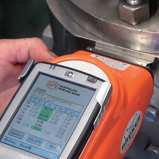
“Australian Pipeline Valve produces isolation, control and flow reversal protection products for severe and critical service media in utility, steam, pipelines, oil & gas and process industries. APV valves and pipeline products form the most competitive portfolio in the market.”
APV FAMILY OF BRANDS RANGE - CATALOGUES
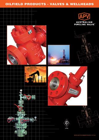
Oilfield Products Valves & Wellheads
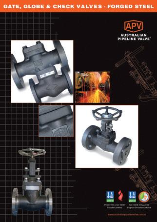
Gate, Globe & Check Valves - Forged Steel
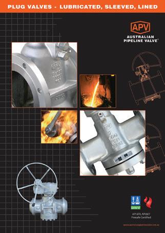
Plug Valves Lubricated, Sleeved & Lined
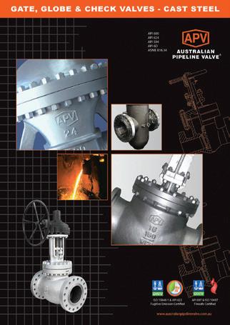
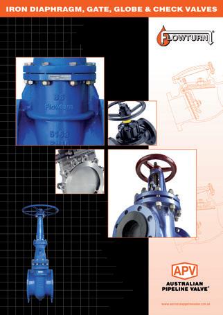
Gate, Globe & Check Valves - Cast Steel
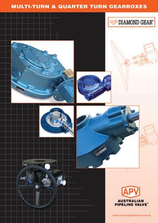
Diamond Gear Gearboxes
Flowturn Gate, Globe & Check Valves
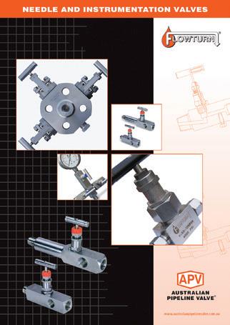
Flowturn Instrument Valves
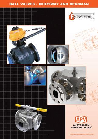
Flowturn Ball Valves Multiway & Deadman
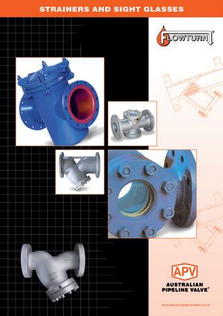
Flowturn Strainers & Sight Glasses
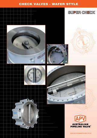
Supercheck Wafer Check Valves
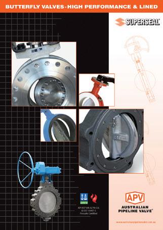
Superseal Butterfly Valves
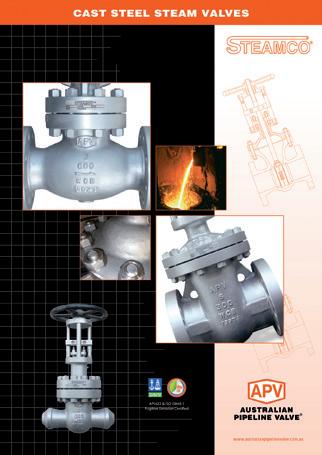
Steamco Steam Valves
Superseal
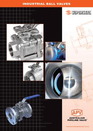
Industrial Ball Valves
TwinLok Tube Fittings
Uniflo Check Valves
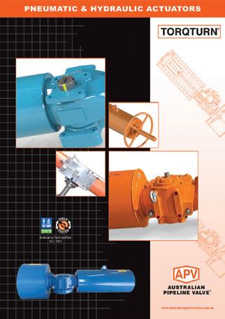
Torqturn Actuators
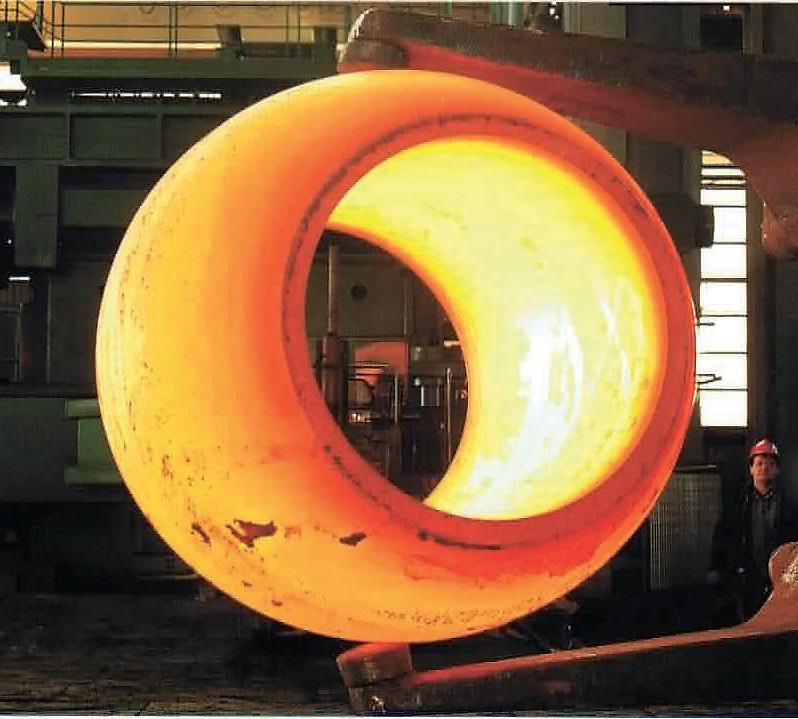
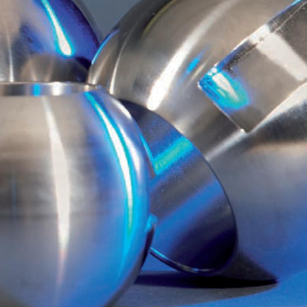
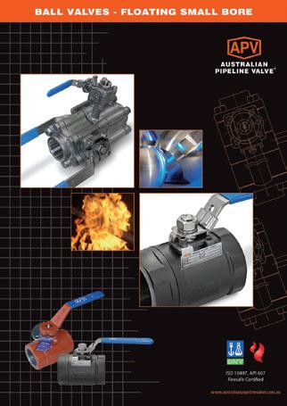
Ball Valves Floating & Trunnion Mounted
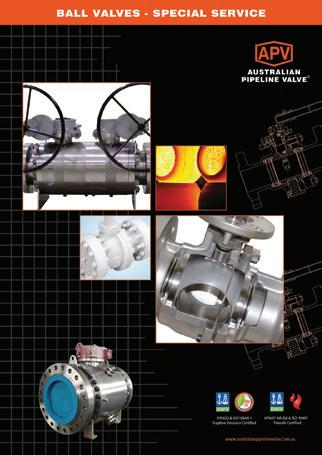
Ball Valves Floating Small Bore Ball Valves Special Service
Product Brochure
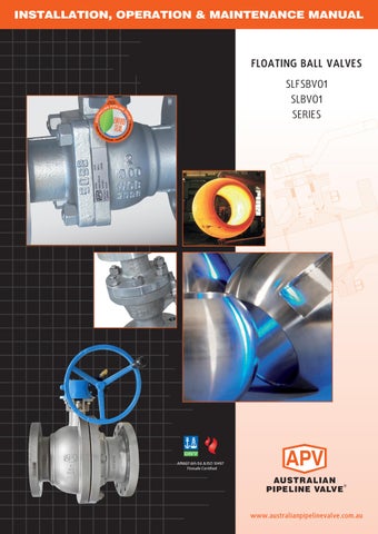
INTRODUCTION
The majority of this information is common knowledge to experienced valve users. When properly installed in applications for which they were designed, Australian Pipeline Valve (APV) valves will give long reliable service. This instruction is only a guide for installation and operation on standard service and covers general maintenance and minor repairs. A professional APV approved valve engineering facility should be utilised for reconditioning or major repairs.
Note
We recommend that this entire document be read prior to proceeding with any installation or repair. Australian Pipeline Valve and it’s parent company take no responsibility for damage or injury to people, property or equipment. It is the sole responsibility of the user to ensure only specially trained valve repair experts perform repairs under the supervision of a qualified supervisor.
RESPONSIBILITY FOR VALVE APPLICATION
The User is responsible for ordering the correct valves. The user is responsible for ensuring APV Valves are selected and installed in conformance with the current pressure rating and design temperature requirements. Prior to installation, the valves and nameplates should be checked for proper identification to ensure the valve is of the proper type, material and is of a suitable pressure class and temperature rating to satisfy the requirements of the service application.
Do not use valves in applications where either the pressure or temperature is higher than the allowable working values. Also valves should not be used in service media if not compatible with the valve material of construction, as this will cause chemical attacks, leakage, valve failure.
RECEIVING INSPECTION AND HANDLING
Valves should be inspected upon receipt to ensure:
- Conformance with all purchase order requirements.
- Correct type, pressure class, size, body and trim materials and end connections.
- Any damage caused during shipping and handling to end connections, hand wheel or stem.
The User is advised that specifying an incorrect valve for the application may result in injuries or property damage. Selecting the correct valve type, rating, material and connections, in conformance with the required performance requirements is important for proper application and is the sole responsibility of the user.
CONSIDERATIONS OF TECHNICAL RISK/ LIMIT OF LIABILITY TO CLIENT FOR BALL VALVES
Australian Pipeline Valve don’t consider in our design the following factors of risk:
1. Australian Pipeline Valve ‘Standard’ ball valves can be used in a temperature range between -28.8 to +200°C. (Note, pressure limitations apply above 38°C refer to Pressure/Temperature charts.) For service temperatures below -28.8°C ball valve construction materials shall be submitted to an impact test at the minimum service temperature. For temperatures outside of the range of -28.8°C to +200°C ball valves have to be provided with seats, seals and body material able to withstand the temperature degree required.
2. The onus is on the customer to specify all materials of construction and service conditions. Australian Pipeline Valve shall assume standard materials and conditions if not otherwise specified.
3. Australian Pipeline Valve ‘Standard’ ball valves are not equipped with devices suitable to avoid internal over-pressures caused by incorrect operations of process or by-fluids & liquids subjected to an increase of volume and/or pressure (these devices, such as the over-pressure hole in the ball or safety seats are available upon request).
4. Australian Pipeline Valve ‘Standard’ ball valves are not designed with special devices to withstand a sudden thermal jump (thermal shock).
5. In general Australian Pipeline Valve ‘Standard’ ball valves are not mechanically designed to bear overloads due to exceptional atmospheric or natural phenomenon’s (such as earthquakes).
6. In general Australian Pipeline Valve ‘Standard’ ball valves are not designed to bear loads on flanges, on pipe connections or pipeline.
7. In general Australian Pipeline Valve ‘Standard’ ball valves can’t withstand ice inside their bodies (in this case user must specify the optional stem extension for insulating, avoiding the presence of residual product inside the valve).
8. Australian Pipeline Valve ‘Standard’ ball valves are not suitable for low temperature service below -29°C (-20°F) unless provided with cryogenic stem extension and other modifications (available on request).
9. Australian Pipeline Valve ‘Standard’ ball valves are suitable for ‘industrial’ oxygen (not medical) service when supplied degreased and packed in polyethylene bags only.
10. The compatibility between ball valves construction materials and medium is selected by the user. The user is ultimately responsible for verifying the compatibility between medium and materials.
11. Abrasive or dirty service, high temperature service, low temperature service, vacuum service, near zero pressure service and other special applications should be clearly stated when requesting quotation.
12. Floating valves without supplementary upstream relief hole in ball cannot be used for unstable fluids which, if trapped in the body cavity (valves in closed position) can be subject to the risk of increasing of pressure due to the increasing of temperature. If required, the purchaser must specify an upstream relief hole.
13. Valves without fugitive emission extensions cannot be used for toxic or dangerous medium with the risk of dispersion in the environment.
14. For fluids like oxygen, hydrogen or chlorine where the contact with oil or grease can create explosions valves that have not been properly cleaned, degreased and sealed in suitable boxes cannot be used. Avoid any kind of contamination until the moment of use. The same precautions have to be applied to valves for cryogenic services.
BALL VALVE START-UP
Before installing the ball valve onto the pipe-line it is mandatory for the user to verify the compatibility of the ball valve with service conditions (medium, temperature and pressure). With reference to standard ball valves held in stock the reseller and end user will have to assure themselves of the compatibility with the use of conditions required by the customer. Australian Pipeline Valve ball valves must be only used for on-off (fully open/fully closed) service.
Before using the ball valve in a potential explosive atmosphere it’s necessary: -
• To verify the compatibility between the ball valve and the zone in which the ball valve should be installed.
• To foresee the pipe-line ground condition on which the ball valve should be installed.
• To check that the temperature of the ball valve surface is not higher than the flammable point of the atmosphere in which the ball valve is installed (in this case specify an insulating cover device for the valve and an extension for the wrench)
• Before installing ball valves with welding ends to make sure that the process of welding is carried out in accordance with all the safety requirements of the classified zone.
• To avoid mechanical knocks during the installation that may cause sparks.
Australian Pipeline Valve cannot be held responsible for damage caused by use of the product especially if it is improper use or modified.
SAFETY INFORMATION
The following general safety information should be taken in account in addition to the specific warnings and cautions specified in this manual. They are recommended precautions that must be understood and applied during operation and maintenance of the equipment covered in this I.O.M.
Never attempt to disassemble a valve while there is pressure in the line. Ensure both upstream and downstream pressures are removed. Disassemble with caution in case all pressures are not relieved. Even when replacing stem packing, caution is necessary to avoid possible injury.
To prevent valve bending, damage, inefficient operation, or early maintenance problems, support piping on each side of the valve. When handling gases/fluids that could cause damage to human health, the environment or property, the necessary safety precautions to prevent risk must be taken.
• A valve is a pressurised mechanism containing energised fluids under pressure and consequently should be handled with appropriate care.
• Valve surface temperature may be dangerously too hot or too cold for skin contact.
• Upon disassembly, attention should be paid to the possibility of releasing dangerous and or ignitable accumulated fluids.
• Ensure adequate ventilation is available for service.
This manual provides instructions for storing, general servicing, installation and removal of ball valves. APV and it’s resellers refuse any liability for damage to people, property or plant as well as loss of production and loss of income under any circumstances but especially if caused by: Incorrect installation or utilisation of the valve or if the valve installed is not fit for the intended purpose. It is the sole responsibility of the user to ensure the valve type and materials are correctly specified.
SCOPE OF INSTALLATION ACCORDING TO THE TYPE OF FLUID (DANGEROUS FOR THE ENVIRONMENT OR HUMAN HEALTH)
Group 1 Classification
- The incorporation of additional safety elements “Double Packing” (utilising a stem extension) is recommended for the range of products included in Group 1.
- The use of valves without additional safety devices in Group 1 will be the responsibility of the user or the purchaser, as well as the advisability of installing leakage detection systems.
Group 2 Classification
- Carbon steel valves will not be used in corrosive fluid lines.
DURING OPERATION TAKE INTO ACCOUNT THE FOLLOWING WARNINGS:
a- Graphite/Graphoil packing and body gasket is very brittle, any impacting, twisting or bending should be avoided.
b- The valve’s internal parts such as ball, stem, seats, seals, gaskets shall be handled with care avoiding scratches or surface damage.
c- All tools and equipment for handling internal critical sealing parts shall be soft coated.
d- Valves can be fitted with gaskets or seals in PTFE, Buna, Viton, etc., hence high temperatures will damage sealing components.
e- Never part open valve. Valve must be full open of full closed to avoid seal damage.
For all operations make reference to position number on part list of the applicable drawing listed.
1.0 SCOPE
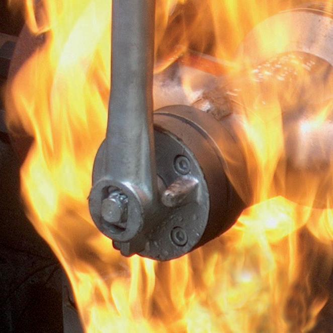
This manual describes the methods of installation and maintenance for floating ball valves, which are designed to fit between ANSI Class 150, Class 300 and Class 600 flanges or with buttweld ends. SLFSBV01 is firesafe, SLBV01 is not firesafe.
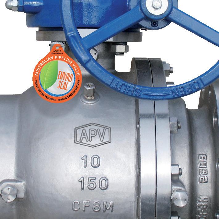
1.1 ENVIRONMENTAL CONSIDERATIONS
According to ISO 14000 regulations and the environmental policy of APV, the recyclability of the components that form part of APV valves is as follows:
Recyclable components:
Metal parts, PTFE (hard), plastic plug (low-density polyethylene).
Non-recyclable components:
PTFE mixed with other compounds (glass-fiber, graphite, etc.), nylon, graphite and graphite mixed with metal.
1.2 STORAGE
1.2.1 Temporary Storage
If valves are to be stored before installation, the following should be observed:
a) Keep the valves wrapped and protected as shipped from the manufacturer.
b) Do not remove the protective end covering until the valve is ready for installation. This will reduce the possibility of foreign material damaging the internal valve components.
c) Valves stored outdoors should be positioned such that water does not accumulate in the valve body.
1.2.2
Long Term Storage
If valves are to be stored more than one year, they should be prepared in the following manner:
a) Remove the packing and apply a preservative to the packing chamber.
b) Do not remove the protective end covering.
c) Do not store the valves outdoors.
1.3 PREPARATION
a) Remove the valve end protection.
b) Prior to shipment, a preservative/corrosion inhibitor may have been applied to the inner body of the valve. This preservative/corrosion inhibitor can be removed with a solvent provided the solvent used does not affect the seats/seals used in the valve.
c) The inside of the valve should be inspected and blown out with compressed air. Adjacent piping must be clean and free from debris to prevent damage to the valve.
d) To prevent valve distortion, inefficient operation or early maintenance problems, support piping on each side of the valve.
e) Make sure the valve is positioned such that there is sufficient space so that the hand wheel is easily and safely reached and there is enough clearance for the stem when the valve is open.
f) Install the valve according to the flow indicator on the valve body where applicable.
2.0 INSTALLATION
Piping should be properly aligned and supported to reduce mechanical loading on end connections. Never use the lever (wrench) to hold the valve during transport, handling or assembly.
The following procedure is required to be followed for correct installation.
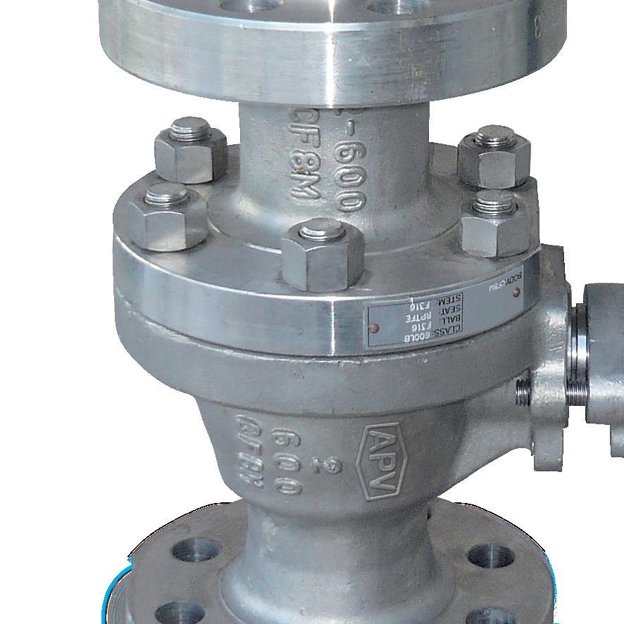
a) Before installation confirm the marking (rating, size and material) on the valve body and nameplate. Ensure the valve is suitable for the service which it is being used.
b) Body bolts and nuts on valve shall be checked and retightened if necessary in case loosened during installation.
c) Remove valve end protectors and ensure gasket faces are free from damage. Tighten all bolts between mating flanges and valve equally paying careful attention to properly tighten bolts. Ensure you rotate tightening procedure (opposing bolts sequentially) gradually increasing torque. Refer to Appendix Table 3 for tightening sequence.
d) Prior to installation of valve, ensure the line is completely flushed to remove any debris as soft seated ball valves are easily damaged. Filters or strainers should be installed upstream to protect soft seated valves.
e) Valves will operate at any angle horizontally or vertically, although it is recommended you install valves in a vertical position with stem pointing upwards for ease of operation, inspection and accessibility.
2.1 INSTALLATION POSITIONS
Ball valves are usually bi-directional, and therefore may be installed in either direction. In some cases, ball valves such as ‘metal to metal’ seated and low temperature valves may be uni-directional, in which case the direction of flow will be indicated on the valve body.
2.2 PREPARATION FOR INSTALLATION
• Remove protective end caps or plugs and inspect valve ends for damage to threads, weld ends or flange faces.
• Thoroughly clean adjacent piping system to remove any foreign material that could cause damage to seating surfaces during valve operation.
• Verify that the space available for installation is adequate to allow the valve to be installed and to be operated.
2.3 END CONNECTIONS
2.3.1 Threaded
Ends
Check condition of threads on mating pipe. Apply joint compound to the male end of joint only. This will prevent compound from entering the valve flowpath.
2.3.2 Flanged
Ends
Check to see that mating flanges are dimensionally compatible with the flanges on the valve body ensure sealing surfaces are free of debris. Install the correct studs and nuts for the application and place the gasket between the flange facings.
Stud nuts should be tightened in an opposing criss-cross pattern in equal increments to ensure even gasket compression. Refer table 1 and 2 in Appendix.
2.3.3 Socket weld
Ends
Remove all debris, grease, oil, paint, etc., from the pipe that is to be welded into the valve and from the valve end connections.
Insert the pipe into the valve end connection until it bottoms out in the socket weld bore. Withdraw the pipe 1/16” so that a gap remains between the pipe and the bottom of the socket weld bore to prevent cracks (ASME B16.11). Tack the pipe into the valve and complete the fillet weld.
WELDING INSTRUCTIONS
• Local welding regulations and specification must be complied with when carrying out welding work.
• Remove any paint and rust around the weld area on the pipe and welded end of the ball valve.
• Check that the ball valve is correctly positioned and aligned with the pipeline.
• Where weld connection is close to seat area, due to short length of the welded ends there is a risk that the soft inserts may be destroyed during the welding work. Hence the following procedure is advised:Use temperature measuring strips to check that the temperature does not rise beyond the permissible limits (160°C). The strips must be fitted to the connection near the soft inserts. These temperature measurements strips are designed so that, when a type-dependent temperature is reached, the colour irreversibly changes from white to black. The temperature measurement strip must be monitored constantly throughout the welding work. If any change of colour is noticed, the welding work must be interrupted immediately and the weld allowed to cool.
2.3.4 Buttweld End Valves
Clean the weld ends as necessary and weld into the line using an approved weld procedure. Make sure the pipe and valve body material given on the valve body or nameplate is compatible with the welding procedure. (Refer our compatibility cross reference chart for equivalent pipe, valve & fittings grades at the Technical section of our website). Soft seats can be damaged during welding, take steps to ensure valve is not over heated, especially smaller size valves (see above caution note).
2.4 VALVE INSTALLATION BY WELDING
Leave valves in the full open position during installation, welding and post-weld heat treatment. This will reduce temperature transmission to soft seats. After welding completion, open the valve and flush line to clean out any foreign matter. Valves over 65 NB ( 2 1/2”) have minimal risk of temperature damage to seats.
For valves up to 80 NB (3”) the welding temperature can adversely affect the PTFE and elastomer components. Follow the welding instructions above and use temperature measuring strips to monitor temperature. It will be the responsibility of the operator to ensure valves are kept cool during welding and then post-weld testing of the valve should be performed. Larger size valves over 80 NB (3”) are less likely to transmit heat to seat and stem packing during welding but still care should be taken. Depending on class, valves under 50 NB (2”) should have pup ends fitted to avoid seat damage. If not fitted ensure valve body temperature is kept cool. Temperatures over 180°C can damage seats & seals.
The responsibility for welding of the valves into piping systems is that of those performing the welding. Refer to ASME B31.1, B31.3 etc. Written welding procedures covering all attributes of the process and materials to be welded shall be in accordance with Section IX of the ASME Boiler and Pressure Vessel Code and any additional requirements from the applicable piping code including any possible necessary localised post weld heat treatment depending on material specifications.
3.0
OPERATION
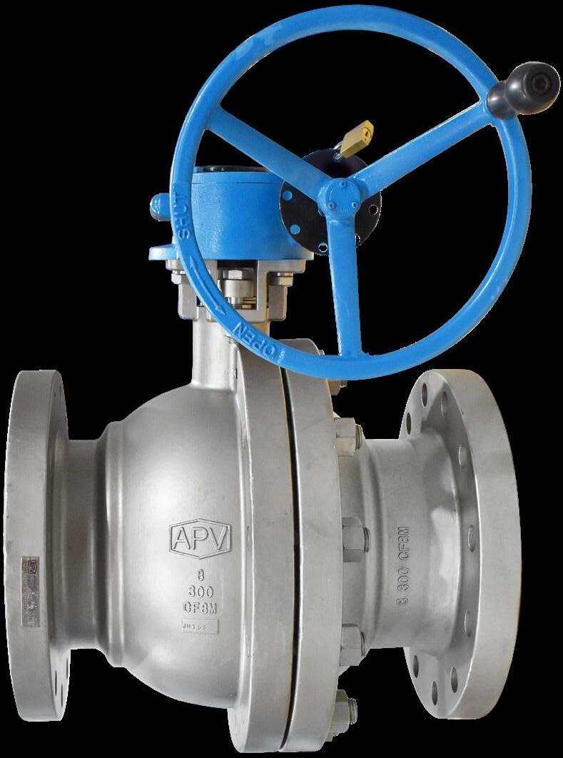
3.1 MANUAL OPERATION
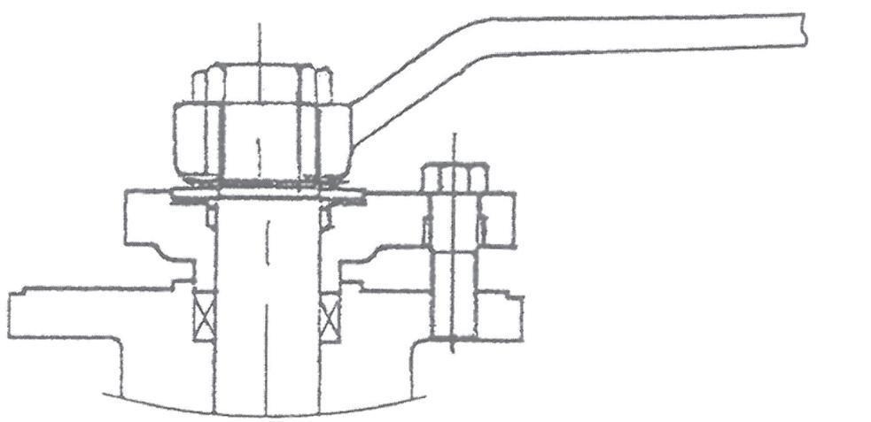
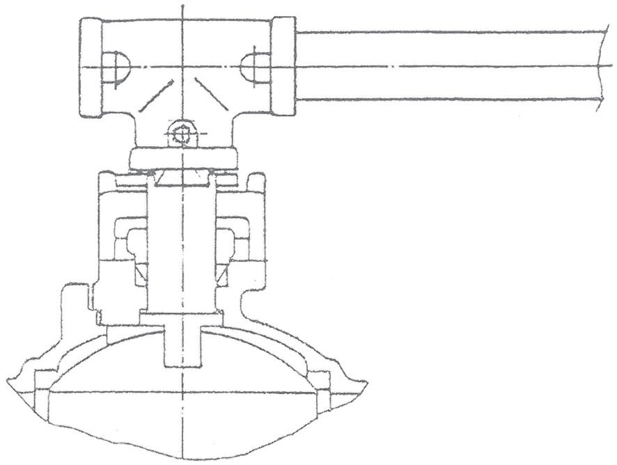
Valve adjustment is by clockwise turning of stem. Lever operated and gear operated valves have a position indicator to indicate open or closed (see figure 1 & 2). Ball Valves must not be used for throttling. Do not leave part open, or seats will be damaged. Valve must be full open or full closed.
3.2 LOCK DEVICE
Where provided (optional) the valve has a locking lug that allows valve to be locked in full open or full closed position.
Floating valves without supplementary upstream relief hole in ball cannot be used for unstable fluids which, if trapped in the body cavity (valves in closed position) can be subject to the risk of increasing of pressure due to the increasing of temperature. If required, the purchaser must specify an upstream relief hole.
Valves without fugitive emission extensions cannot be used for toxic or dangerous medium with the risk of dispersion in the environment. For fluids like oxygen, hydrogen or chlorine where the contact with oil or grease can create explosions valves that have not been properly cleaned, degreased and sealed in suitable boxes cannot be used. Avoid any kind of contamination until the moment of use. The same precautions have to be applied to valves for cryogenic services.
FIG 1.
FIG 2.
4.0 MAINTENANCE
Valves should be periodically checked at least once every 3 months, but depending on service, criticality and frequency of use, more regular checking may be required.
Packing leakage could result in personal injury. Valve packing is tightened prior to shipping but may require adjustment to meet specific service conditions. If valve does not fully close, damage to the seat and body will result due to the venturi effect resulting in high pressure erosion. Flush or remove the valve at next opportunity.
A good program of inspection and maintenance cannot be overstressed. It is recommended that the valve be periodically and at least partially stroked/function tested to ensure the valve functions and prevent seizure/sticking of any mating surfaces. Duration depends on service, criticality etc. However it also must be factored in that if there are impurities or particulates in the line each operation could reduce seat life proportionately. Periodic inspection of critical leak-path areas such as body/bonnet joint, end connections, seating surfaces, and around the stem packing should be a requirement.
The most common area for leakage is around the stem packing, this is usually due to wear and can normally be stopped by adjusting the packing. This procedure is performed by turning gland bolts or nut (8) 1/2 turn at a time until leakage stops. Once leakage stops, continue tightening gland plate nuts an additional 1/2 turn. If leakage cannot be halted by adjusting packing, repacking of the valve is indicated. (Refer to field repair).
4.1 GLAND PACKING
In case of slight leakage from the gland, gland packing bolts or nuts can be lightly tightened up without effecting torque. (see 4.0) See Figure 3 and 3.1 and 4 and table 3 in the Appendix for the bolted style glands.
Do not attempt to repack or replace stem while the valve is in service! Only graphite packing is to be used for firesafe service, PTFE is not firesafe. SLFSBV01 is firesafe only when fitted with graphite packing and graphite or spiral wound graphite filled body gasket. The part number code on the label will indicate stem packing and body gasket. Model SLBV01 is not firesafe, only SLFSBV01 is firesafe.
4.1.1 Stem Leakage – Stem Packing Replacement
The most common point for leakage is around the stem and packing this leakage can normally be stopped by adjustment of the packing gland. If this does not stop the valve leakage, the valve will have to be repacked.
The system and valve MUST be depressurised before attempting any repair work. After removing all pressure from the valve and draining the system the following procedure should be used to repack the valve.
1. Remove nuts or screw from the lever. Remove the lever and lock plate. Remove the gland plate bolts or nut and remove the gland plate and gland. If the gland retainer is a double nut type then remove both nuts and anti vibration washer.
2. Remove old packing, taking care not to scratch or damage the stem of stuffing box. Note, the stem design is anti-blow out so the stem cannot be removed up through the top of the valve.
3. Clean and inspect stem, stuffing box, and gland. If any scratches, nicks, or corrosion is found, the parts should be replaced.
4. Slide each packing ring over the stem and into packing chamber. Carefully tap each ring into place and continue installing rings until the recommended number of rings have been installed. A thin smear of molybdenum sulfide anti-seize grease may be used on the stem and packing chamber wall for packing lubrication.
5. Replace gland, gland plate, and gland plate bolts. Tighten nuts alternately in 1/2 turn increments until a reasonable torque (refer table 2 in the Appendix) is applied to lightly compress packing. Lubricate stem and cycle valve through a couple of complete cycles.
6. If slight stem leakage occurs after system is pressurised, continue tightening gland plate bolts or gland nut in alternating 1/2 turn increments until leakage stops. Once leakage stops, continue tightening gland plate nuts and additional 1/2 turn. If valve becomes too difficult to turn, back off 1/2 a turn. There is also a PTFE seal ring/bearing and larger sizes/higher classes also have an elastomer o-ring. However, these parts can only be replaced during complete disassembly of the valve. If a PTFE stem o-ring is fitted it can be replaced with an elastomer o-ring suitable for the service medium and temperature. PTFE o-rings require pre softening in hot water prior to fitting. Should replacement of packing fail to prevent the leakage, complete reconditioning of the valve may be required.
Personal injury may result from sudden release of any process pressure. APV recommends the use of protective clothing, gloves and eye wear when performing any installation or maintenance. Isolate the valve from the system and relieve pressure prior to performing maintenance. Disconnect any operating lines providing air pressure, control signals or electrical power to actuators.
Bolted yoke type packing retainer
Nut type packing retainer
FIG 3. CONSTRUCTION FOR GLAND PARTS
FIG 3.1 CONSTRUCTION FOR GLAND PARTS
(*Depending on class, seat type, etc.)
4.2 BODY SEAL
Sealing between two body segments is provided with a gasket (Teflon, spiral wound or graphite) and both valve segment surfaces also provide metal to metal sealing. In case of slight leakage the fastening bolts can be lightly tightened up.
If a gasket seal is disturbed while removing or adjusting gasketed parts, APV recommends installing a new gasket while reassembling. A proper seal is required to ensure optimum operation.
4.2.1
Body Gasket Tightening
Should leakage occur at the body/bonnet joint, tighten bonnet bolts to the values shown in Table 1 (refer Appendix). If after tightening body bolts, leakage continues, replacement of gasket is recommended. A new gasket is recommended anytime the valve is disassembled. The following procedure shown in 4.3 is recommended for the replacement of the gasket and other trim components.
FIG 4. ALTERNATE CONSTRUCTION FOR GLAND PARTS 150NB*
CAP BODY
GASKET
METAL TO METAL
FIG 5. STRUCTURE OF GASKET IN BODY JOIN
4.3 INSPECTION AND REPLACEMENT OF TRIM COMPONENTS
Disassembly: -
1. Place the valve in the half open position and remove all pressure and drain the system. Make sure that leakage of any residual material is caught in an appropriate container and disposed of properly.
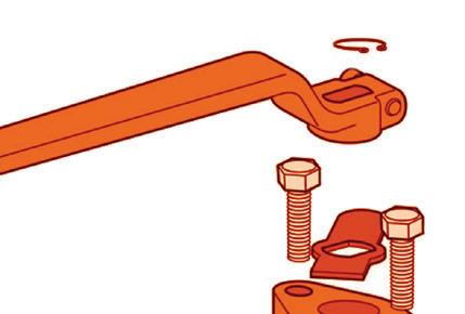
2. For gear operator or power actuator operated: - remove the bolt fastening the gearbox or power actuator. Remove the gear operator or power actuator. Remove the bolt fastening the yoke or yoke nut (depending on size/class).
3. For lever operated: - remove the screw or circlip fastening the lever. Remove the lever. Remove the retainer/lock washer and the stop plate.
4. Follow disassembly procedure 4.4 below.
5. Remove the ball from the body. Check the ball for any damage. Remove the seat from the body. Check the seat for any damage.
6. Remove the stem and thrust plate from the body. Remove the thrust plate from the stem. Check the stem for any damage.
7. Clean and inspect body and retainer gasket surfaces. Check for erosion, corrosion, or damage, especially near point where leakage occurred. If damage is found, those surfaces must be repaired before continuing.
8. Replace or repair all damaged parts.
Reassembly: -
1. Installation of new seats, packing and seals is recommended, then follow reassembly procedure 4.5 below.
2. For gear operator or power actuator operated: - install the yoke and tighten the screws.
2a. Install key on the stem.
2b. Install gear operator on top flange and tighten the bolts.
3. For lever operated: - install stop plate.
3a. Install retainer/thrust washer.
3b. Install lever.
3c. Install washer and tighten the screw or fit circlip.
This completes the reassembly.
4.4 DISASSEMBLY PROCEDURE
Before removing valve from line ensure valve is in the closed position and line is fully closed off and drained. Client should observe all industry & regulatory procedures in this process. To disassemble first remove the operator (4.3.2) then the following steps should be followed with reassembly in reverse order.
1. Drain & clean valve including contents in cavity.
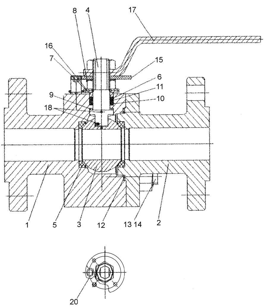
2. Remove (13) CAP BOLT and (14) NUT from (1) BODY and (2) CAP.
3. Take off (2) CAP from (1) BODY and remove (12) GASKET.
6. Remove (16) SNAP RING (or retainer bolt), (15) STOPPER, (8) GLAND BOLT and (7) GLAND FLANGE (or GLAND NUT) on larger sizes YOKE must also be removed.
7. Remove (4) STEM by pulling from inside BODY cavity.
8. Remove (9) THRUST WASHER.
9. Remove (11) GLAND PACKING and (10) STEM SEAL where fitted.
4.5 REASSEMBLY PROCEDURE
1. For reassembly of the disassembled valves, follow the above disassembling procedure in the reverse order.
2. After cleaning the disassembled parts, reset each part in the original position properly. The threaded parts should be cleaned thoroughly and applied with lubricating paste.
3. The stuffing box and base of gasket should be thoroughly cleaned with care.
Check the packing box for pressurised process fluids even after the valve has been removed from the pipeline, particularly when removing packing hardware or packing rings, or removing packing box pipe plug.
4. The gland packing and gasket should be replaced preferably each time the valve is disassembled.
5. To reassemble body and cap, each bolt and nut shall be pre greased and then tightened in accordance with applicable Torque as per Table 1 (see Appendix).
Note
Nylon and Devlon are hard and more scratch resistant compared to Teflon®, and PEEK is harder still. However, Teflon® is more resilient and has better ‘memory’ in terms of resistance to permanent indentations. All soft seated valves are only suited to clean service applications.
6. After installation of new parts: Reassemble using reverse order of steps outlined above. Operate valve several times to be assured of smooth operation before reinstalling.
4.6
TEST
Testing in accordance with API 598. For API 6D, refer to test procedure in API 6D - 2021 section I.7.4.
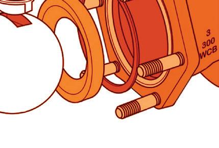
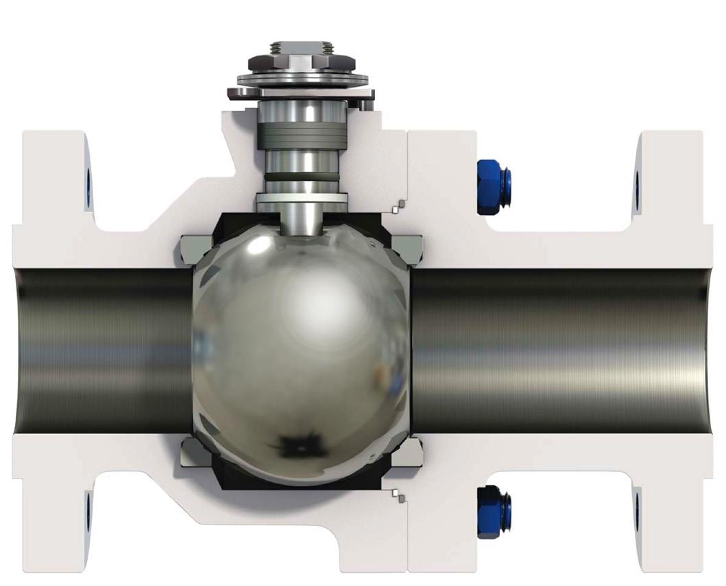
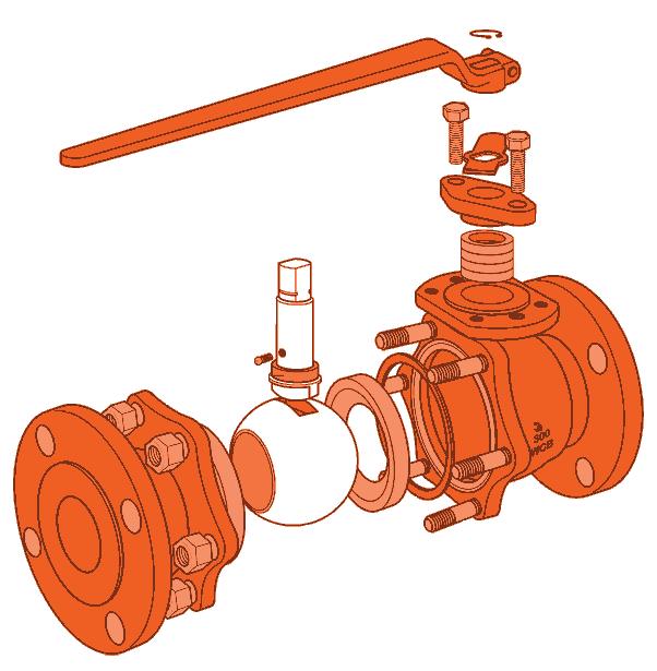
Following is a typical disassembly explosion of an APV floating 2 piece ball valve. The number of parts will slightly vary in each size & class but the principal components are as per Figure 6/6A below. Refer to as-built drawing supplied with the valve for actual bill of material.
Snap ring or bolt washer, depending on size/class
The
FIG 6. VALVE DESIGN CAST (BOLTED GLAND VERSION)
*1 Gland flange or gland nut in smaller sizes
*2 Depends on size & class
*3 Snap ring or bolt washer, depending on size/class.
The above is indicative only, design depends on size, class and trim, etc. Refer to as-built drawing.
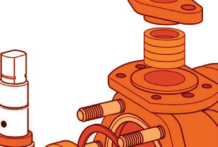
6.0 OPTIONAL ARRANGEMENT
OPTIONAL DIRECT MOUNT PAD VERSION COMPLETE WITH LIVE LOADED STEM SEALS
APV Ball Valves fitted with a ‘direct mount pad’ often utilise a stem seal arrangement where the seals are retained by a stem or packing nut, with ‘live-loading’ of the stem seals. This live loading is accomplished by the addition of Belleville (also known as disc) springs below the packing nut . The purpose of live loading the stem seals is to maintain the initial sealing load on the seals as they wear, or as they compress further, reducing or eliminating the need for frequent packing nut adjustments. The Belleville springs perform this function by storing compressive force as the packing nut is tightened, and releasing this force as packing wear or compression occurs.
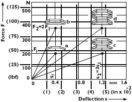
In the cases where they are supplied on APV valves, the springs are installed in “series”, or stacked with outer diameters touching, rather than in “parallel”, where the dished springs would be nested together. The arrangement of 2 springs in series provides essentially the same pre-load as a single spring when compressed, and a spring stroke double that of a single spring. Where 2 (or more) springs are installed in parallel, the spring load is the multiple of a single spring times the number in parallel, but the spring stroke is still that of a single spring. For examples, see the following:
CHARACTER LINES FOR SPRING STACKS WITH SPRINGS OF THE SAME SIZE ARRANGED IN DIFFERENT ORDER
a) Single disc
b) Two discs stacked in parallel (double force at same deflection)
c) Spring column with three* single springs stacked in series (triple deflection)
d) Spring column with three* parallel pairs arranged in series (double force, triple deflection)
* Used in very high pressures or severe service.
Unless otherwise specified, 2 springs in series is used for live loaded stem seal arrangements. The springs have been designed and sized to provide the packing load required when the springs area compressed, and the series arrangement provides sufficient spring travel to ensure that a suitable compressive force remains applied as the stem seals wear, or compress. Manual lever operated valves fitted with ‘direct mount pads’ are supplied with 2 Belleville springs mounted in series, to provide superior stem sealing for critical service applications and lower maintenance. The other reason is, valves fitted with direct mount pads are often utilised for direct mounting of actuators and as accessing the stem packing would require actuator removal, a live loaded packing system avoids or reduces maintenance (however, open brackets can be fitted allowing room to adjust packing). For very large sizes in higher pressure classes we often use 4 springs in series.
Adding more springs in series is generally not required (a longer stroke is not needed), as in smaller sizes & lower pressure classes APV use quality 301 grade heavy gauge Belleville springs so even if using a direct mount actuator the 2 spring series usually requires none or very infrequent adjustment.
APPENDIX 1
Bolting Torques
TABLE 1
Note:
(1) Torques shown are for A193 B7/B7M/B8/B8M and A320 L7/L7M/B8/B8M.
(2) Torque tolerance ±10%.
(3) For temperatures above 750°F (400°C) use 75% of the torque values.
(4) Above torque values are with the bolts lubricated.
(5) Values above are based on 30,000 psi (206.85 Mpa) bolting stress and lubricated with heavy graphite and oil mixture or a copper based anti-seize grease.
(6) Do not exceed by more than 25% of values stated when emergency torquing is required.
(7) All bolts shall be torqued in the pattern as shown in Table 3 in Appendix to ensure uniform gasket loading.
(8) Optimum torque can vary depending on type of body gasket but do not increase torque more than 10% above those shown.
(9) Consult us for other bolt material.
(10) Most B8M and B8 bolts are class 1 so do not assume class 2 unless you are sure.
Bolt tensions shown in Table 1 & 2 must be decreased by 25% when other or no lubrication used. Non lubricated bolts can have an efficiency of up to 50% less than the torque of values stated.
Indicative torques are shown only, different body gasket systems, different seating styles, different sizes & classes, etc., will have different torque requirements. Furthermore, other stud grades can have much lower torques depending if class 1 or class 2 and or above variables.
APPENDIX 1 (CONTINUED)
TABLE 2 BODY BOLT TIGHTENING SEQUENCE
TABLE 3
GLAND PACKING TORQUE In Lb (Nm)
STUD DIAMETER TORQUE VALUE in/lb (Nm)
THREAD PITCH in (mm) GLAND TORQUE NEVER EXCEED
5/16 - 18 (8) 48 (5.4)
5/16 - 18 (8) 48 (5.4)
3/8 - 16 (10) 84 (9.5) 105 (11.9)
3/8 - 16 (10) 84 (9.5) 105 (11.9)
3/8 - 16 (10) 84 (9.5) 105 (11.9)
7/16 - 14 (11) 132 (14.9) 165 (18.7)
1/2 - 13 (13) 204 (23.1) 225 (25.5)
1/2 - 13 (13) 204 (23.1) 225 (25.5)
9/16 - 12 (14) 252 (28.5) 315 (35.6)
5/8 - 11 (16) 396 (44.8) 495 (56.0)
This table only applies to bolted style glands, not nut style.
STUD LUBRICATION
PRESSURE RATINGS WITH REINFORCED - PTFE
CF8-150LB A B C D
A. Valve size 15A (1/2”) to 25A (1”)
B. Valve size 40A (1 1/2”) to 65A (2 1/2”)
C. Valve size 80A (3”) to 100a (4”)
D. Valve size 125A (5”) to 250A (10”) Carbon PTFE & PEEK will do higher temperatures
• Re-tightening of body bolts (with system de-pressurised) and gland packing bolting is permissible, if leakage occurs in these areas.
• Required Torque values are given in Tables 1 & 2.
• The use of copper-based Anti-seize grease for body and packing stud lubrication and molybdenum disulfide anti-seize grease for stem packing lubrication is recommended.
• Bolt tension should be decreased by 25% from values shown in Tables 1 & 2 when other or no lubrication is used.
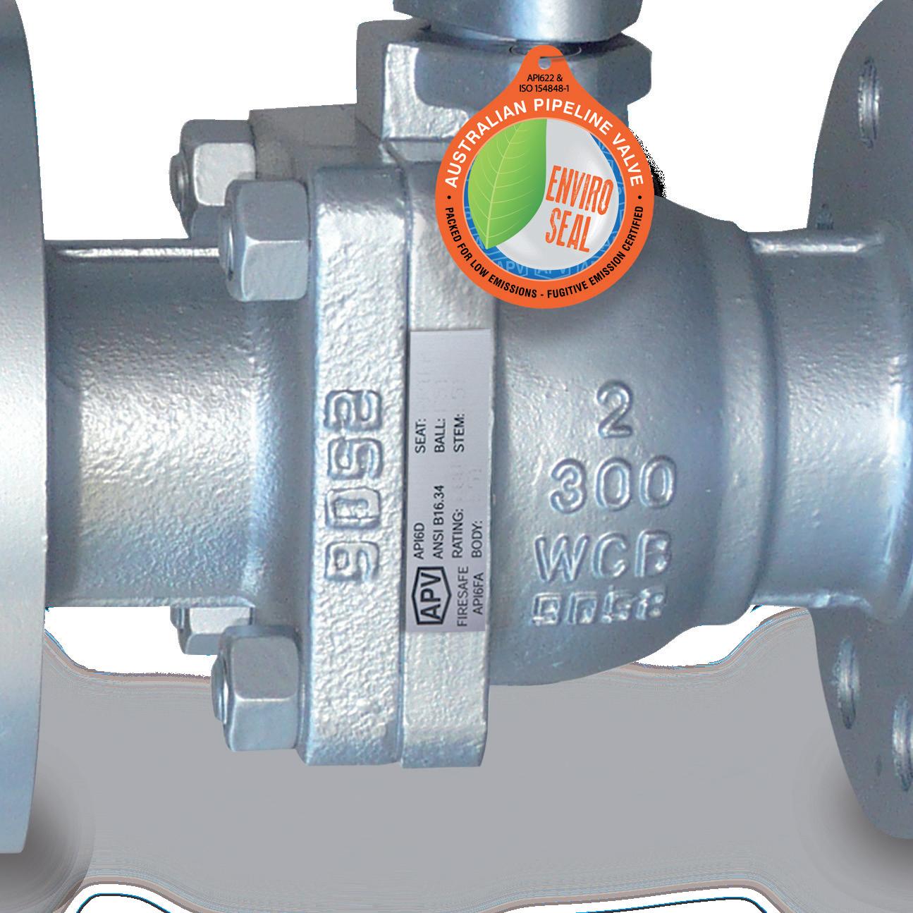
APPENDIX 2
Label details
DIAGRAM 2
No. Figure Number Code Description
1 Figure Number Identifies the detailed valve confirguation (valve type, bore size, pressure class, materials, etc.)
2 Serial Number Identifies certified manufacturers serial number & stock code
3 Firesafe Identifies firesafe standard
4 Standard Identifies manufacturing design & standard
5 Body Material Identifies body material composition (A105, WCB, F51, CF8M, etc.)
6 Pressure Classes Identifies pressure classification per API requirements
7 Size Identifies bore size
8 Seat Material Identifies seat material composition (PEEK, Teflon, Nylon, etc.)
9 Ball Material Identifies ball/disc material composition (A105, 316SS, ENP, etc.)
10 Stem Material Identifies stem material composition (A105, 410SS, 17-4pH, etc.)
11 MAX WP @ Identifies maximum pressure at minimum temperature
12 MAX WP @ Identifies maximum pressure at maximum temperature
* NACE MR0175 Identifies corrosion resistance
6D Ball Label
* NACE is indicated by a separate NACE tag.
WARRANTY
1. LIMITED WARRANTY: Subject to the limitations expressed herein, Seller warrants that products manufactured by Seller shall be free from defects in design, material and workmanship under normal use for a period of one (1) year from installation but in no case shall the warranty period extend longer than eighteen months from the date of sale. This warranty is void for any damage caused by misuse, abuse, neglect, acts of God, or improper installation. For the purpose of this section, “Normal Use” means in strict accordance with the installation, operation and maintenance manual. The warranty for all other products is provided by the original equipment manufacturer.
2. REMEDIES: Seller shall repair or replace, at its option, any non-conforming or otherwise defective product, upon receipt of notice from Buyer during the Manufacturer’s warranty period at no additional charge. SELLER HEREBY DISCLAIMS ALL OTHER EXPRESSED OR IMPLIED WARRANTIES, INCLUDING, WITHOUT LIMITATION, ALL IMPLIED WARRANTIES OF MERCHANTABILITY AND FITNESS OR FITNESS FOR A PARTICULAR PURPOSE.
3. LIMITATION OF LIABILITY: UNDER NO CIRCUMSTANCES SHALL EITHER PARTY BE LIABLE TO THE OTHER FOR INCIDENTAL, PUNITIVE, SPECIAL OR CONSEQUENTIAL DAMAGES OF ANY KIND. BUYER HEREBY ACKNOWLEDGES AND AGREES THAT UNDER NO CIRCUMSTANCES, AND IN NO EVENT, SHALL SELLER’S LIABILITY, IF ANY, EXCEED THE NET SALES PRICE OF THE DEFECTIVE PRODUCT(S) PURCHASED DURING THE PREVIOUS CONTRACT YEAR.
4. LABOR ALLOWANCE: Seller makes NO ADDITIONAL ALLOWANCE FOR THE LABOR OR EXPENSE OF REPAIRING OR REPLACING DEFECTIVE PRODUCTS OR WORKMANSHIP OR DAMAGE RESULTING FROM THE SAME.
5. RECOMMENDATIONS BY SELLER: Seller may assist Buyer in selection decisions by providing information regarding products that it manufacturers and those manufactured by others. However, Buyer acknowledges that Buyer ultimately chooses the product’s suitability for its particular use, as normally signified by the signature of Buyer’s technical representative. Any recommendations made by Seller concerning the use, design, application or operation of the products shall not be construed as representations or warranties, expressed or implied. Failure by Seller to make recommendations or give advice to Buyer shall not impose any liability upon Seller.
6. EXCUSED PERFORMANCE: Seller will make a good faith effort to complete delivery of the products as indicated by Seller in writing, but Seller assumes no responsibility or liability and will accept no back-charge for loss or damage due to delay or inability to deliver, caused by acts of God, war, labor difficulties, accidents, inability to obtain materials, delays of carriers, contractors or suppliers or any other causes of any kind whatever beyond the control of Seller. Under no circumstances shall Seller be liable for any special, consequential, incidental, or indirect damages, losses, or expense (whether or not based on negligence) arising directly or indirectly from delays or failure to give notice of delay.