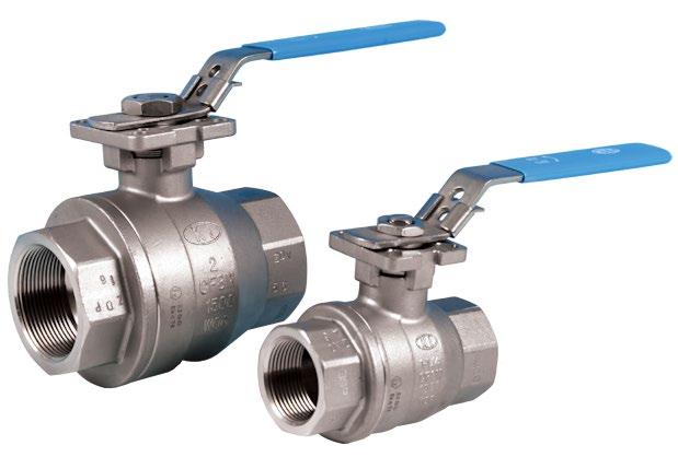
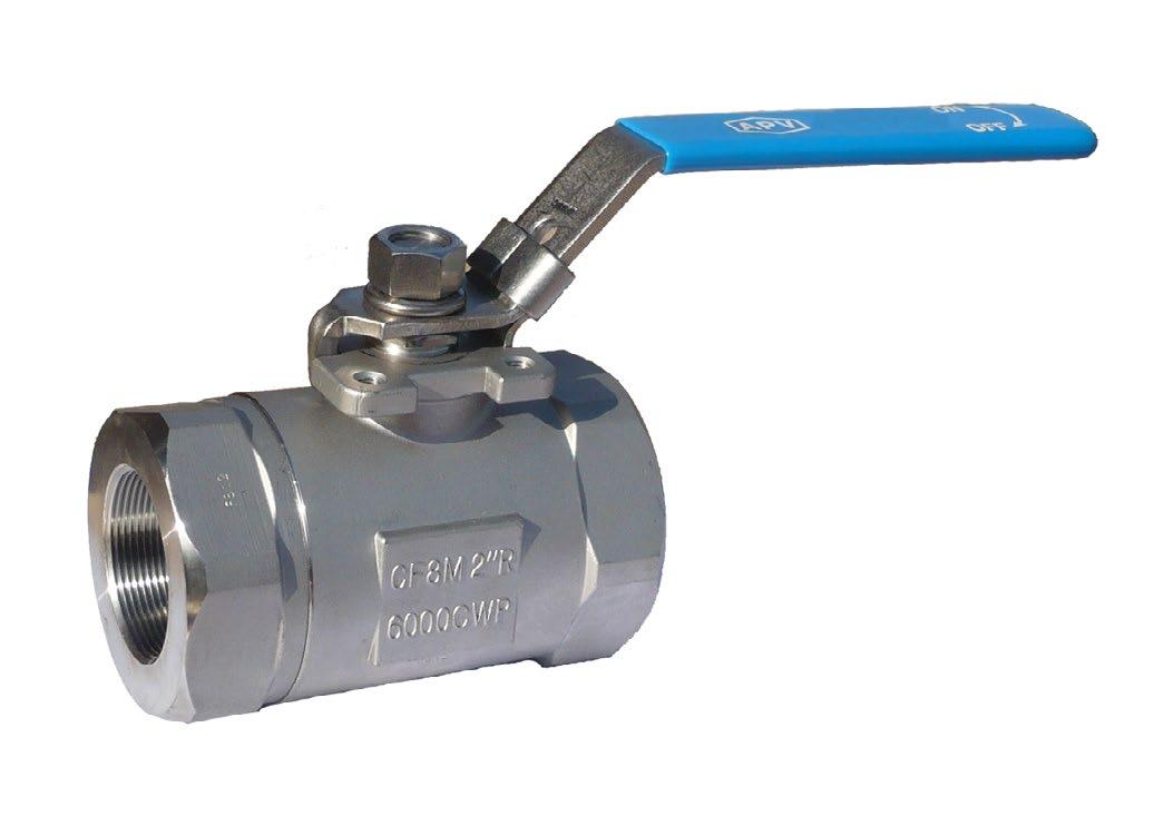


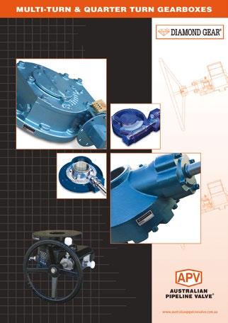
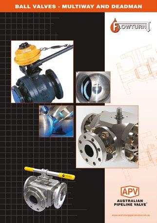
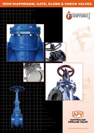
COMPLETE PRODUCT LINE
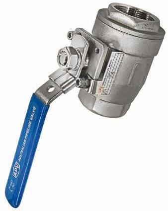
“Australian Pipeline Valve produces isolation, control and flow reversal protection products for severe and critical service media in utility, steam, pipelines, oil & gas and process industries. APV valves and pipeline products form the most competitive portfolio in the market.”
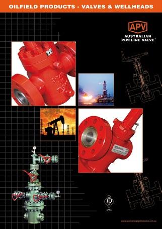
APV FAMILY OF BRANDS RANGE - CATALOGUES
INTRODUCTION
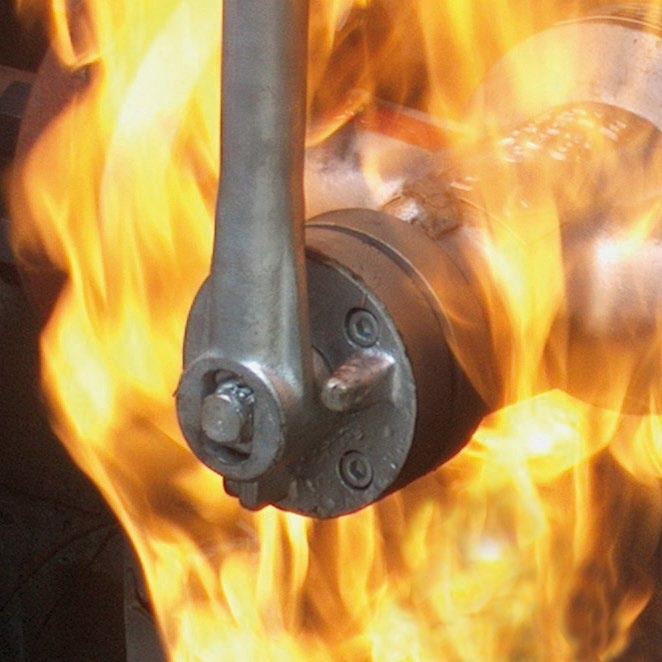
The majority of this information is common knowledge to experienced valve users. When properly installed in applications for which they were designed, Australian Pipeline Valve (APV) valves will give long reliable service. This instruction is only a guide for installation and operation on standard service and covers general maintenance and minor repairs. A professional APV approved valve engineering facility should be utilised for reconditioning or major repairs. Check the part number on the label to ensure the valve is configured to firesafe specifications if firesafe is required.
Note
We recommend that this entire document be read prior to proceeding with any installation or repair. Australian Pipeline Valve and it’s parent company take no responsibility for damage or injury to people, property or equipment. It is the sole responsibility of the user to ensure only specially trained valve repair experts perform repairs under the supervision of a qualified supervisor.
RESPONSIBILITY FOR VALVE APPLICATION
The User is responsible for ordering the correct valves. The user is responsible for ensuring APV Valves are selected and installed in conformance with the current pressure rating and design temperature requirements. Prior to installation, the valves and nameplates should be checked for proper identification to ensure the valve is of the proper type, material and is of a suitable pressure class and temperature rating to satisfy the requirements of the service application.
Do not use valves in applications where either the pressure or temperature is higher than the allowable working values. Also valves should not be used in service media if not compatible with the valve material of construction, as this will cause chemical attacks, leakage, valve failure.
RECEIVING INSPECTION AND HANDLING
Valves should be inspected upon receipt to ensure:
- Conformance with all purchase order requirements.
- Correct type, pressure class, size, body and trim materials and end connections.
- Any damage caused during shipping and handling to end connections, hand wheel or stem.
The User is advised that specifying an incorrect valve for the application may result in injuries or property damage. Selecting the correct valve type, rating, material and connections, in conformance with the required performance requirements is important for proper application and is the sole responsibility of the user.
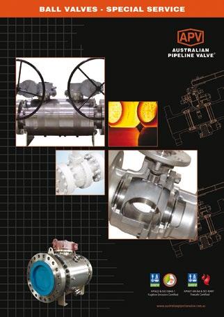
CONSIDERATIONS OF TECHNICAL RISK/ LIMIT OF LIABILITY TO CLIENT FOR BALL VALVES
Australian Pipeline Valve don’t consider in our design the following factors of risk:
1. Australian Pipeline Valve ‘Standard’ ball valves can be used in a temperature range between -28.8 to +200°C. (Note, pressure limitations apply above 38°C refer to Pressure/Temperature charts.) For service temperatures below -28.8°C ball valve construction materials shall be submitted to an impact test at the minimum service temperature. For temperatures outside of the range of -28.8°C to +200°C ball valves have to be provided with seats, seals and body material able to withstand the temperature degree required.
2. The onus is on the customer to specify all materials of construction and service conditions. Australian Pipeline Valve shall assume standard materials and conditions if not otherwise specified.
3. Australian Pipeline Valve ‘Standard’ ball valves are not equipped with devices suitable to avoid internal over-pressures caused by incorrect operations of process or by-fluids & liquids subjected to an increase of volume and/or pressure (these devices, such as the over-pressure hole in the ball or safety seats are available upon request).
4. Australian Pipeline Valve ‘Standard’ ball valves are not designed with special devices to withstand a sudden thermal jump (thermal shock).
5. In general Australian Pipeline Valve ‘Standard’ ball valves are not mechanically designed to bear overloads due to exceptional atmospheric or natural phenomenon’s (such as earthquakes).
6. In general Australian Pipeline Valve ‘Standard’ ball valves are not designed to bear loads on flanges, on pipe connections or pipeline.
7. In general Australian Pipeline Valve ‘Standard’ ball valves can’t withstand ice inside their bodies (in this case user must specify the optional stem extension for insulating, avoiding the presence of residual product inside the valve).
8. Australian Pipeline Valve ‘Standard’ ball valves are not suitable for low temperature service below -29°C (-20°F) unless provided with cryogenic stem extension and other modifications (available on request).
9. Australian Pipeline Valve ‘Standard’ ball valves are suitable for ‘industrial’ oxygen (not medical) service when supplied degreased and packed in polyethylene bags only.
10. The compatibility between ball valves construction materials and medium is selected by the user. The user is ultimately responsible for verifying the compatibility between medium and materials.
11. Abrasive or dirty service, high temperature service, low temperature service, vacuum service, near zero pressure service and other special applications should be clearly stated when requesting quotation.
12. Floating valves without supplementary upstream relief hole in ball cannot be used for unstable fluids which, if trapped in the body cavity (valves in closed position) can be subject to the risk of increasing of pressure due to the increasing of temperature. If required, the purchaser must specify an upstream relief hole.
13. Valves without fugitive emission extensions cannot be used for toxic or dangerous medium with the risk of dispersion in the environment.
14. For fluids like oxygen, hydrogen or chlorine where the contact with oil or grease can create explosions valves that have not been properly cleaned, degreased and sealed in suitable boxes cannot be used. Avoid any kind of contamination until the moment of use. The same precautions have to be applied to valves for cryogenic services.
BALL VALVE START-UP
Before installing the ball valve onto the pipe-line it is mandatory for the user to verify the compatibility of the ball valve with service conditions (medium, temperature and pressure). With reference to standard ball valves held in stock the reseller and end user will have to assure themselves of the compatibility with the use of conditions required by the customer. Australian Pipeline Valve ball valves must be only used for on-off (fully open/fully closed) service.
Before using the ball valve in a potential explosive atmosphere it’s necessary: -
• To verify the compatibility between the ball valve and the zone in which the ball valve should be installed.
• To foresee the pipe-line ground condition on which the ball valve should be installed.
• To check that the temperature of the ball valve surface is not higher than the flammable point of the atmosphere in which the ball valve is installed (in this case specify an insulating cover device for the valve and an extension for the wrench)
• Before installing ball valves with welding ends to make sure that the process of welding is carried out in accordance with all the safety requirements of the classified zone.
• To avoid mechanical knocks during the installation that may cause sparks.
Australian Pipeline Valve cannot be held responsible for damage caused by use of the product especially if it is improper use or modified.
SAFETY INFORMATION
The following general safety information should be taken in account in addition to the specific warnings and cautions specified in this manual. They are recommended precautions that must be understood and applied during operation and maintenance of the equipment covered in this I.O.M.
Never attempt to disassemble a valve while there is pressure in the line. Ensure both upstream and downstream pressures are removed. Disassemble with caution in case all pressures are not relieved. Even when replacing stem packing, caution is necessary to avoid possible injury.
To prevent valve bending, damage, inefficient operation, or early maintenance problems, support piping on each side of the valve. When handling gases/fluids that could cause damage to human health, the environment or property, the necessary precautions to prevent risk must be taken.
• A valve is a pressurised mechanism containing energised fluids under pressure and consequently should be handled with appropriate care.
• Valve surface temperature may be dangerously too hot or too cold for skin contact.
• Upon disassembly, attention should be paid to the possibility of releasing dangerous and or ignitable accumulated fluids.
• Ensure adequate ventilation is available for service.
This manual provides instructions for storing, general servicing, installation and removal of ball valves. APV and it’s resellers refuse any liability for damage to people, property or plant as well as loss of production and loss of income under any circumstances but especially if caused by: Incorrect installation or utilisation of the valve or if the valve installed is not fit for the intended purpose. It is the sole responsibility of the user to ensure the valve type and materials are correctly specified.
SCOPE OF INSTALLATION ACCORDING TO THE TYPE OF FLUID (DANGEROUS FOR THE ENVIRONMENT OR HUMAN HEALTH)
Group 1 Classification
- The incorporation of additional safety elements “Double Packing” (utilising a stem extension) is recommended for the range of products included in Group 1.
- The use of valves without additional safety devices in Group 1 will be the responsibility of the user or the purchaser, as well as the advisability of installing leakage detection systems.
Group 2 Classification
- Carbon steel valves will not be used in corrosive fluid lines.
DURING OPERATION TAKE INTO ACCOUNT THE FOLLOWING WARNINGS:
• Graphite/Graphoil packing and body gasket is very brittle, any impacting, twisting or bending should be avoided.
• The valve’s internal parts such as ball, stem, seats, seals, gaskets shall be handled with care avoiding scratches or surface damage.
• All tools and equipment for handling internal critical sealing parts shall be soft coated.
• Valves can be fitted with gaskets or seals in PTFE, Buna, Viton, etc., hence high temperatures will damage sealing components.
• Never part open valve. Valve must be full open of full closed to avoid seal damage.
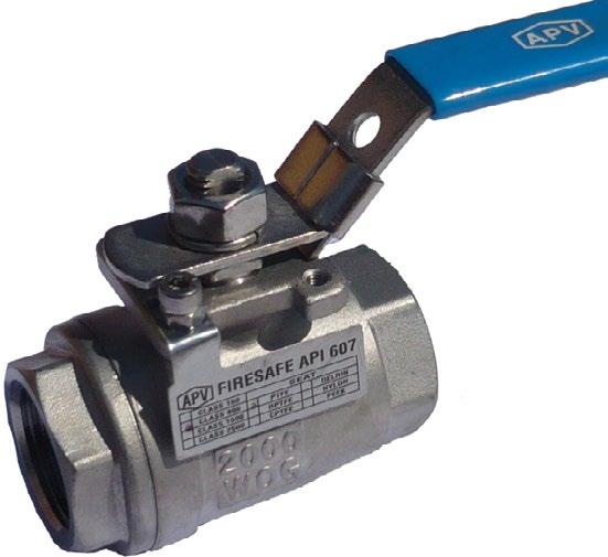
• APV firesafe ball valves are provided with anti-static devices for ball-stem-body. When service conditions require electrical continuity to prevent static discharge, the user is responsible for specifying static grounding.
• When ball valves are to be utilised on liquids with very high velocity, check with the valve distributor or manufacturer for appropriate advice to minimise the possibility of seat deformation, especially when they are highly pressurised on a high-temperature line.
• Ball valves are generally not recommended for throttling service, where both the fluid flow and the leading edge of the ball can damage or deform the resilient ball seats causing leakage. High fluid velocity or the presence of solid particles in suspension will further reduce seat life in throttling applications.
• Do not open the bonnet or cap when bearing pressure. Valve is not equipped with pressure access device. User should check it by other method through its piping system.
• Do not touch the surface of a valve at high temperature.
• Not allowed for unstable fluid unless otherwise specified.
• Lock design on the handle is to avoid the valve being operated by non-related people and is an option upon request.
For all operations make reference to position number on part list of the applicable drawing listed.
1.0 SCOPE
This manual describes the methods of installation and maintenance for floating ball valves, which are designed to fit between ANSI Class 150, Class 300 and Class 600 flanges or with buttweld ends.
1.1
ENVIRONMENTAL CONSIDERATIONS
According to ISO 14000 regulations and the environmental policy of APV the recyclability of the components that form part of APV valves is as follows:
Recyclable components - Metal parts, PTFE (hard), plastic plug (low-density polyethylene).
Non-recyclable components - PTFE mixed with other compounds (glass-fibre, graphite, etc.), nylon, graphite and graphite mixed with metal.
1.2 STORAGE
1.2.1
Temporary Storage
If valves are to be stored before installation, the following should be observed:
a) Keep the valves wrapped and protected as shipped from the manufacturer.
b) Do not remove the protective end covering until the valve is ready for installation. This will reduce the possibility of foreign material damaging the internal valve components.
c) Valves stored outdoors should be positioned such that water does not accumulate in the valve body.
1.2.2
Long Term Storage
If valves are to be stored more than one year, they should be prepared in the following manner:
a) Remove the packing and apply a preservative to the packing chamber.
b) Do not remove the protective end covering.
c) Do not store the valves outdoors.
1.3
PREPARATION
a) Remove the valve end protection.
b) Prior to shipment, a preservative/corrosion inhibitor may have been applied to the inner body of the valve. This preservative/corrosion inhibitor can be removed with a solvent provided the solvent used does not affect the seats/seals used in the valve.
c) The inside of the valve should be inspected and blown out with compressed air. Adjacent piping must be clean and free from debris to prevent damage to the valve.
d) To prevent valve distortion, inefficient operation or early maintenance problems, support piping on each side of the valve.
e) Make sure the valve is positioned such that there is sufficient space so that the hand wheel is easily and safely reached and there is enough clearance for the stem when the valve is open.
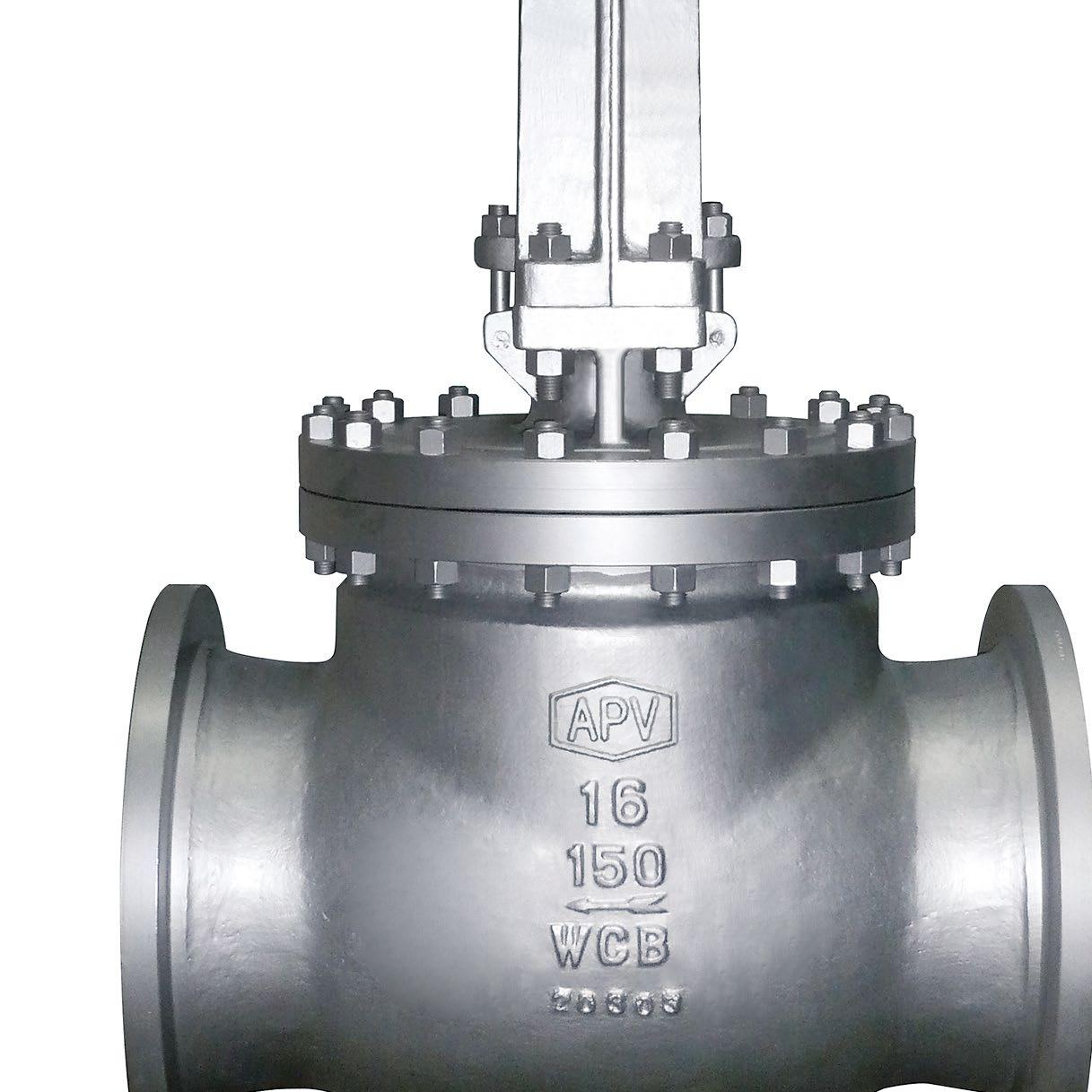
f) Install the valve according to the flow indicator on the valve body where applicable.
2.0 INSTALLATION
Piping should be properly aligned and supported to reduce mechanical loading on end connections. Never use the lever (wrench) to hold the valve during transport, handling or assembly.
The following procedure is required to be followed for correct installation.
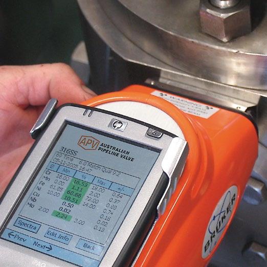
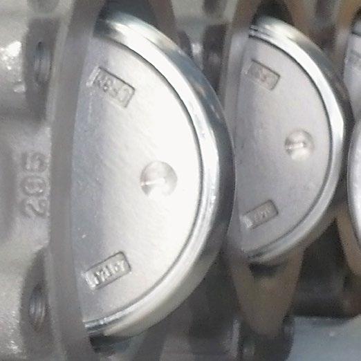
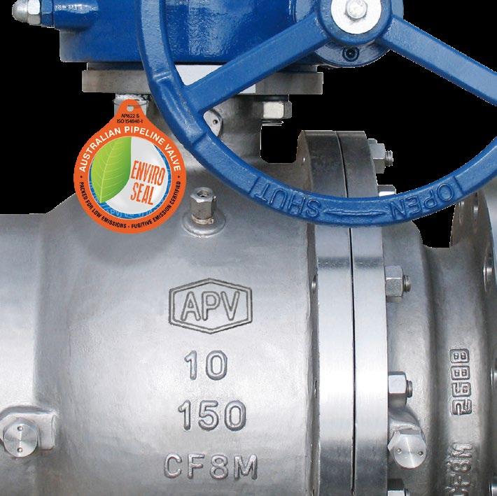
a) Before installation confirm the marking (rating, size and material) on the valve body and name plate. Ensure the valve is suitable for the service which it is being used.
b) Body bolts and nuts on valve shall be checked and re tightened if necessary in case loosened during installation.
c) Remove valve end protectors and ensure gasket faces are free from damage. Tighten all bolts between mating flanges and valve equally paying careful attention to properly tighten bolts. Ensure you rotate tightening procedure (opposing bolts sequentially) gradually increasing torque. Refer to Appendix Table 2 for bolt tightening sequence.
d) Prior to installation of valve, ensure the line is completely flushed to remove any debris as soft seated ball valves are easily damaged. Filters or strainers should be installed upstream to protect soft seated valves.
e) Valves will operate at any angle horizontally or vertically, although it is recommended you install valves in a vertical position with stem pointing upwards for ease of operation, inspection and accessibility.
2.1 INSTALLATION POSITIONS
Ball valves are usually bi directional, and therefore may be installed in either direction. In some cases, ball valves such as ‘metal to metal’ seated and low temperature valves may be uni directional, in which case the direction of flow will be indicated on the valve body.
2.2
PREPARATION FOR INSTALLATION
• Remove protective end caps or plugs and inspect valve ends for damage to threads, weld ends or flange faces.
• Thoroughly clean adjacent piping system to remove any foreign material that could cause damage to seating surfaces during valve operation.
• Verify that the space available for installation is adequate to allow the valve to be installed and to be operated.
Ensure sufficient clearance for the stem in the full open position. Inadequate clearance for valves may add mechanical loading to the valve ends. Sufficient clearance should be allowed for threaded end valves to be ‘swung’ during installation.
2.3 END CONNECTIONS
2.3.1 Threaded Ends
Check condition of threads on mating pipe. Apply joint compound to the male end of joint only. This will prevent compound from entering the valve flow path.
2.3.2 Socket weld Ends
Remove all debris, grease, oil, paint, etc., from the pipe that is to be welded into the valve and from the valve end connections.
Insert the pipe into the valve end connection until it bottoms out in the socket weld bore. Withdraw the pipe 1/16” so that a gap remains between the pipe and the bottom of the socket weld bore to prevent cracks (ASME B16.11). Tack the pipe into the valve and complete the fillet weld.
WELDING INSTRUCTIONS
• Local welding regulations and specification must be complied with when carrying out welding work.
• Remove any paint and rust around the weld area on the pipe and welded end of the ball valve.
• Check that the ball valve is correctly positioned and aligned with the pipeline.
• Where weld connection is close to seat area, due to short length of the welded ends there is a risk that the soft inserts may be destroyed during the welding work. Hence the following procedure is advised: -
Use temperature measuring strips to check that the temperature does not rise beyond the permissible limits (160°C). The strips must be fitted to the connection near the soft inserts. These temperature measurements strips are designed so that, when a typedependent temperature is reached, the colour irreversibly changes from white to black. The temperature measurement strip must be monitored constantly throughout the welding work. If any change of colour is noticed, the welding work must be interrupted immediately and the weld allowed to cool. For ‘swing out centre’ design, the centre section containing soft parts can be removed during welding if preferred, see 2.4.1.
2.3.3
Buttweld End Valves
Clean the weld ends as necessary and weld into the line using an approved weld procedure. Make sure the pipe and valve body material given on the valve body or nameplate is compatible with the welding procedure. (Refer our compatibility cross reference chart for equivalent pipe, valve & fittings grades at the Technical section of our website). Soft seats can be damaged during welding, take steps to ensure valve is not over heated, especially smaller size valves (see above caution note).
2.4 VALVE INSTALLATION BY WELDING
For all sizes of valves, leave valves in the full open position during installation, welding and post-weld heat treatment. This will reduce temperature transmission to soft seats. After welding completion, open the valve and flush line to clean out any foreign matter. Valves over 65 NB ( 2 1/2”) have minimal risk of temperature damage to seats.
2.4.1
Method
For valves up to 80 NB (3”) the welding temperature can adversely affect the PTFE and elastomer components. Follow the welding instructions above but also use temperature measuring strips to monitor temperature. It will be the responsibility of the operator to ensure valves are kept cool during
welding and then post-weld testing of the valve should be performed. Larger size valves over 80 NB (3”) are less likely to transmit heat to seat and stem packing during welding but still care should be taken. Valves 80NB (3”) & under must have PUP ends to avoid seat damage.
The below procedures should also be followed:
a) Always ensure there is no pressure or product in the line. Ball valves will be supplied with socket weld ends to ANSI B16.11 or butt weld ends to ANSI B16.25. Welding should be done using procedures and welders qualified under section IX of the ASME boiler and pressure vessel code.
b) Always do as a low temperature weld as necessary to obtain a reliable connection. Use whatever measure necessary to localise heat at the joint, dissipating it before damage can occur to adaptor gaskets and/or seats (the main risk is seats). Use a tempil stick or other temperature indicator on the outside of the valve body (centre section) directly adjacent to adapter end piece) being welded to assure the body temperature does not increase 160°C. Always leave valve in open position during welding but also at least 60 minutes after welding unit valve cools.
c) Where required APV will supply spare body gaskets. Graphite body gaskets are brittle so great care should be taken not to damage.
The responsibility for welding of the valves into piping systems is that of those performing the welding. Refer to ASME B31.1, B31.3 etc. Written welding procedures covering all attributes of the process and materials to be welded shall be in accordance with Section IX of the ASME Boiler and Pressure Vessel Code and any additional requirements from the applicable piping code including any possible necessary localised post weld heat treatment depending on material specifications.
3.0 OPERATION
3.1
MANUAL OPERATION
Valve adjustment is by clockwise turning of stem. Lever operated and gear operated valves have a position indicator to indicate open or closed (see figure 1). Ball Valves must not be used for throttling. Do not leave part open, or seats will be damaged. Valve must be full open or full closed or damage to seats or body will occur. FIG 1.
3.2 LOCK DEVICE
Where provided (optional) the valve has a locking lug that allows valve to be locked in full open or full closed position.
Floating valves without supplementary upstream relief hole in ball cannot be used for unstable fluids which, if trapped in the body cavity (valves in closed position) can be subject to the risk of increasing of pressure due to the increasing of temperature. If required, the purchaser must specify an upstream relief hole.
Valves without fugitive emission extensions cannot be used for toxic or dangerous medium with the risk of dispersion in the environment. For fluids like oxygen, hydrogen or chlorine where the contact with oil or grease can create explosions valves that have not been properly cleaned, degreased and sealed in suitable boxes cannot be used. Avoid any kind of contamination until the moment of use. The same precautions have to be applied to valves for cryogenic services.
4.0 MAINTENANCE
Valves should be periodically checked at least once every 3 months, but depending on service, criticality and frequency of use, more regular checking may be required.
Packing leakage could result in personal injury. Valve packing is tightened prior to shipping but may require adjustment to meet specific service conditions. If a valve does not fully close, damage to the seat and body will result due to the venturi effect resulting in high pressure erosion. Flush or remove the valve at next opportunity.
A good program of inspection and maintenance cannot be overstressed. It is recommended that the valve be periodically and at least partially stroked/function tested to ensure the valve functions and prevent seizure/sticking of any mating surfaces. Duration depends on service, criticality etc. However it also must be factored in that if there are impurities or particulates in the line each operation could reduce seat life proportionately. Periodic inspection of critical leak-path areas such as body/bonnet joint, end connections, seating surfaces, and around the stem packing should be a requirement.
The most common area for leakage is around the stem packing, this is usually due to wear and can normally be stopped by adjusting the packing. This procedure is performed by turning gland bolts or nut (9) 1/2 turn at a time until leakage stops. Once leakage stops, continue tightening gland plate nuts an additional 1/2 turn. If leakage cannot be halted by adjusting packing, repacking of the valve is indicated. (Refer to field repair).
Do not attempt to replacing packing or replace stem while the valve is in service! (The stem is blowout proof and can only be removed by disassembling the valve). Only graphite packing is to be used for firesafe service, PTFE is not firesafe. A FS660 valve is firesafe only when fitted with graphite packing and graphite or spiral wound graphite filled body gasket. Check the full part number on the label to ensure the valve is specified as firesafe. If there is no firesafe logo on the label the valve is not firesafe. If the part number indicates PTFE packing or body gasket the valve is not firesafe.
4.1 GLAND PACKING
In case of slight leakage from the gland, gland packing nut(s) can be lightly tightened up without effecting torque.
4.1.1 Stem Leakage – Stem Packing Replacement
The most common point for leakage is around the stem and packing this leakage can normally be stopped by adjustment of the packing gland. If this does not stop the valve leakage, the valve will have to be repacked.
The system and valve MUST be depressurised and removed from the line before attempting any repair work. After removing all pressure from the valve and draining the system the following procedure should be used to repack the valve.
1. Remove nuts or screw from the lever. Remove the lever and lock plate. Remove the gland nuts.
2. Remove old packing, taking care not to scratch or damage the stem of stuffing box. Note, the stem design is anti-blow out so the stem cannot be removed up through the top of the valve.
3. Clean and inspect stem, stuffing box, and gland. If any scratches, nicks, or corrosion is found, the parts should be replaced.
4. Slide each packing ring over the stem and into packing chamber. Carefully tap each ring into place and continue installing rings until the recommended number of rings have been installed. A thin smear of molybdenum sulfide anti-seize grease may be used on the stem and packing chamber wall for packing lubrication.
5. Replace and tighten gland nut(s) alternately in 1/4 turn increments until a reasonable torque is applied to lightly compress packing. Lubricate stem and cycle valve through a couple of complete cycles.
6. If slight stem leakage occurs after system is pressurised, continue tightening gland nut in alternating 1/4 turn increments until leakage stops. Once leakage stops, continue tightening gland plate nuts and additional 1/4 turn. There is also a PTFE seal ring/bearing and some models also have an elastomer o-ring. However, these parts can only be replaced during complete disassembly of the valve. If a stem o-ring is fitted it can be replaced with an elastomer o-ring suitable for the service medium and temperature. Should replacement of packing fail to prevent the leakage, complete reconditioning of the valve may be required.
Personal injury may result from sudden release of any process pressure. APV recommends the use of protective clothing, gloves and eye wear when performing any installation or maintenance. Isolate the valve from the system and relieve pressure prior to performing maintenance. Disconnect any operating lines providing air pressure, control signals or electrical power to actuators.
4.2 BODY SEAL
Sealing between the threaded body is provided by a gasket (Teflon or graphite) and both valve segment surfaces also provide metal to metal friction fit sealing. In larger sizes or higher pressures an elastomer o-ring may also be used. In case of slight leakage check the threaded body joint is properly tightened up.
If a gasket seal is disturbed while removing or adjusting gasketed parts, APV recommends installing a new gasket while reassembling. A proper seal is required to ensure optimum operation.
4.3 TROUBLESHOOTING
MALFUNCTION
Valve does not rotate or operate
Ball/Seat Leaking
Stem Packing Leaking
Body Gasket Leaking
POSSIBLE CAUSE
1. Packing is dropped too tightly.
2. The stem is damaged or there is dirt.
3. The times or on-off operation are too many or debris exists on the surface of the ball.
1. Valve not fully closed.
2. Seat or ball damaged.
3. Debris trapped in valve.
1. Packing gland nut loose.
2. Packing damaged or missing.
3. Seal misaligned.
1. Body joint.
2. Body gasket damaged.
Note
REDIAL ACTION
1. Loosen packing and adjust again.
2. Pull apart the valve and clean the dirt.
1. Close the valve tightly.
2. Replace seat or ball.
3. Clean the debris.
1. Tighten gland nut.
2. Replace packing (shut down first).
3. Replace and align it correctly.
1. Tighten body nut.
2. Replace the gasket.
Nylon and Devlon are hard and more scratch resistant compared to Teflon®, and PEEK is harder still. However, Teflon® is more resilient and has better ‘memory’ in terms of resistance to permanent indentations. All soft seated valves are only suited to clean service applications.