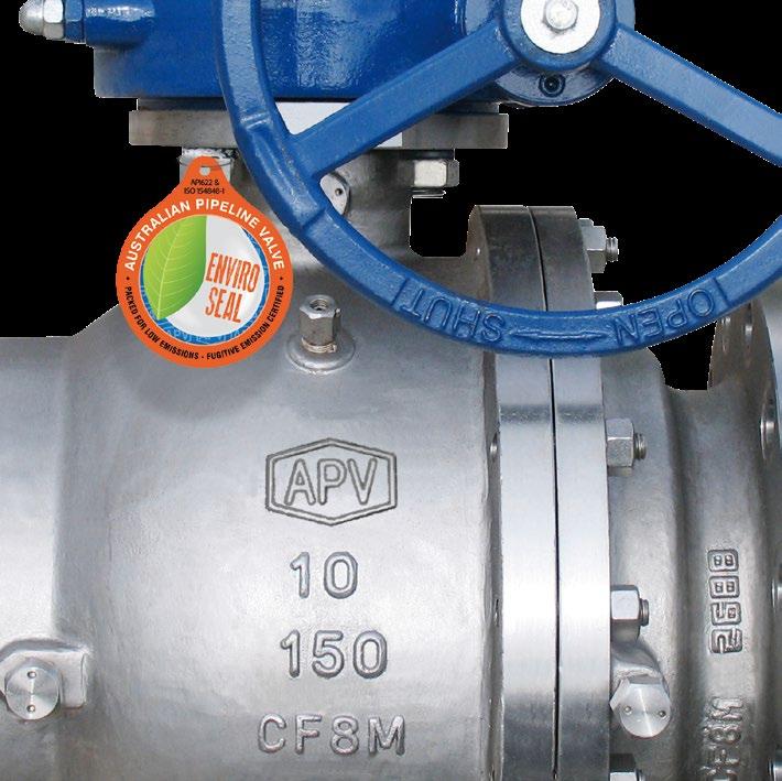
VALVE IDENTIFICATION
Each APV valve is identified with a nameplate. Below is an example.
9
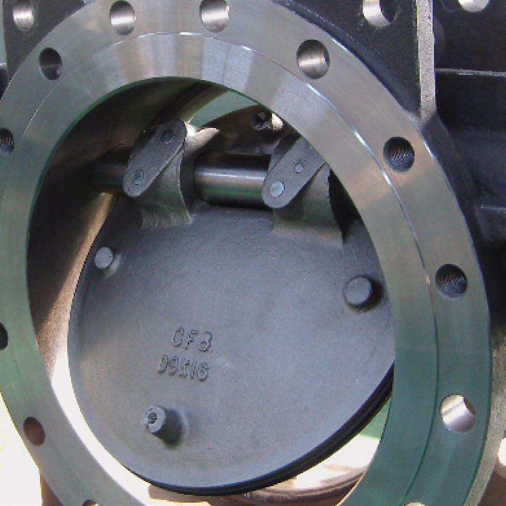
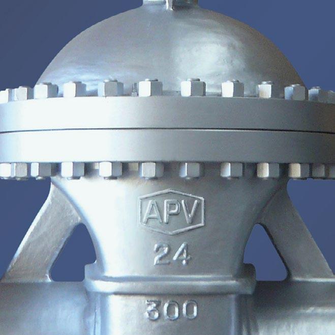
When performing any work, ordering spare parts, or requesting technical support, please refer to this tag. The serial number, the part number and numbers cast on the side of the valve body are keys to proper valve identification.
Australian Pipeline Valve - Installation, Operation and Maintenance Manual 5 WAFER PATTERN CHECK VALVES - ‘SLP’ & ‘SW’ STYLE
CLASS BODY SEAT MODEL SIZE API594 MAX TEMP ASME B16.34 FLAPS SERIAL NO CWP@38ºC 9 7 1 8 4 3 2 5 6 ITEM DESCRIPTION
APV valve figure number which delineats the as-built valve type, body, trim, features, packing, NACE, etc. 2 Shell material (e.g. body) 3 Closure member material (e.g. flap) 4 Seat material 5 Rated pressure class as per ASME B16.34. Section 2 6 Nominal pipe size 7 Serial/batch number
Maximum Pressure Rating @ 38ºC (as per ASME B16.34/ API594)
1
8
Maximum Temperature
1.0 OVERVIEW
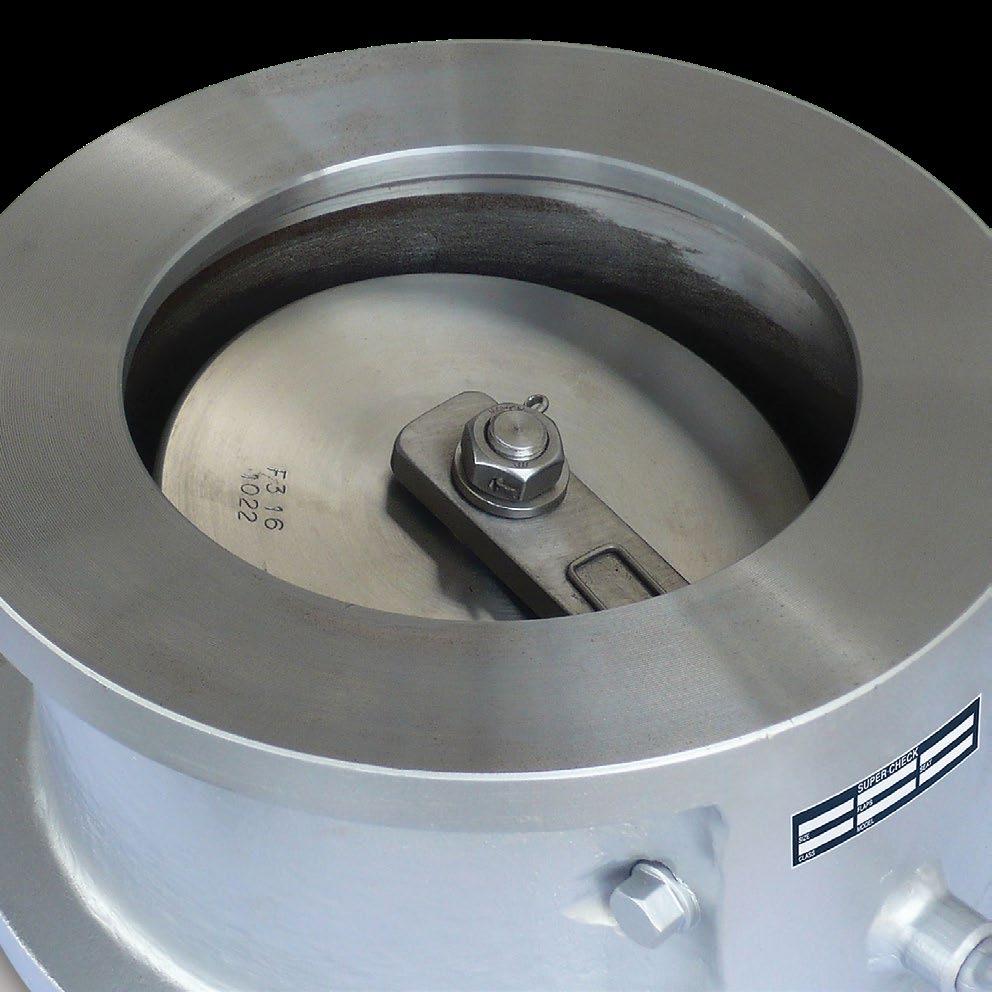
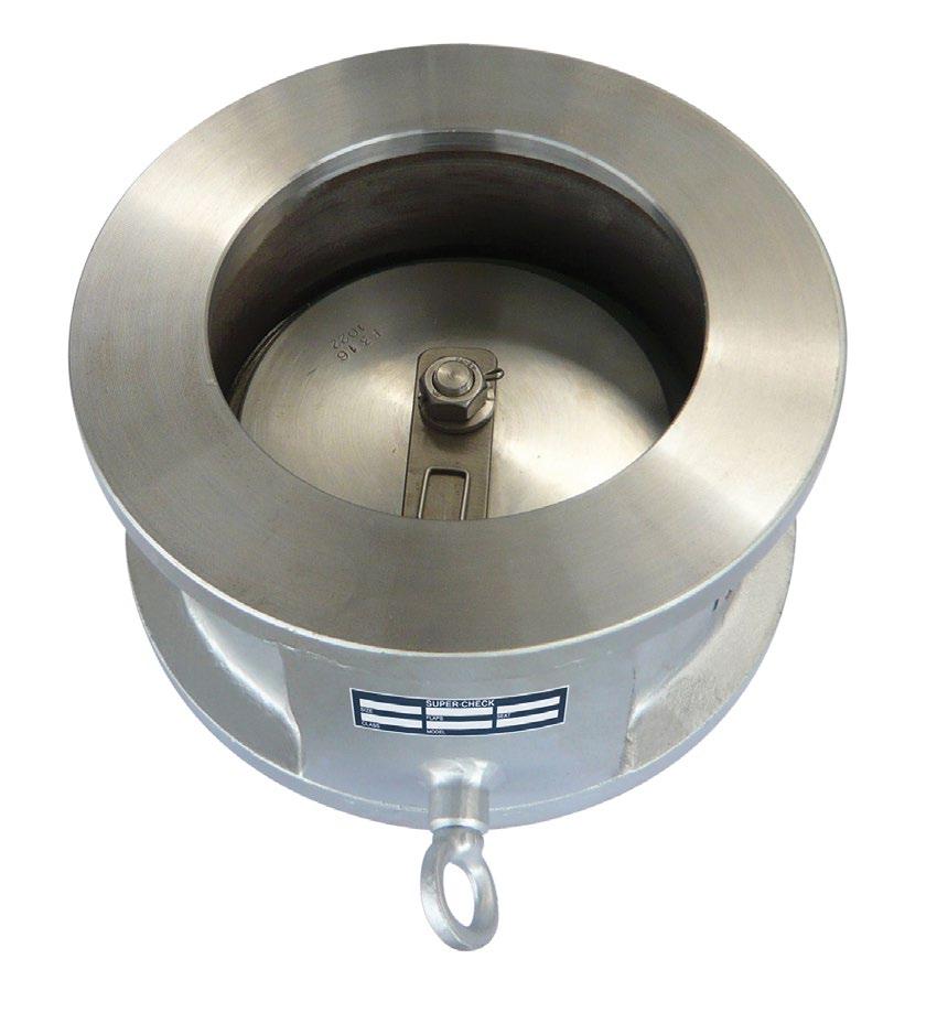
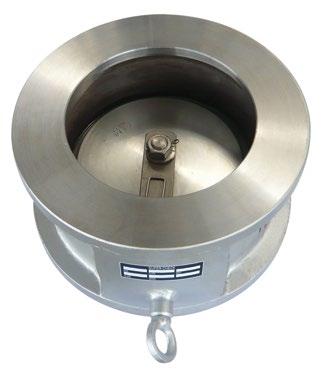
The SW series is retainerless. The SLP is non retainerless through pinned, design and lends itself to the applications requiring limit/micro switches, counter weights, etc. The SLP and SW flapper has spring assisted closing, suitable for horizontal or upwards vertical service (downwards required an external closing spring, which is an available option in SLP series). A large bore provides a larger flow when compared to dual flap style or slim line uniflap checks.
Light and strong
Supercheck SLP/SW series valves are light, so line stress is reduced to a minimum. Yet the installed valve assembly is more rigid than an equivalent length of heavy-walled pipe.
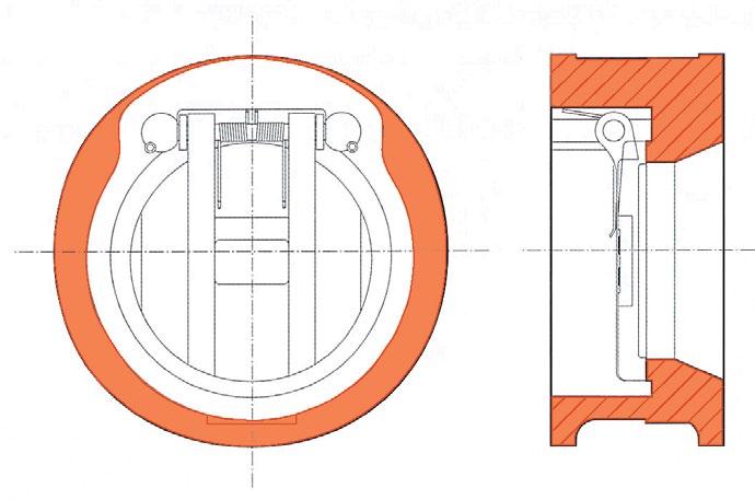
Smooth, fully automatic operation
The SLP/SW series valves are designed to be fully automatic in function. The smooth opening and closing action reduces line hammer to a minimum. SLP/SW series valves are engineered to present an essentially unobstructed orifice.
Simplified design
The SLP/SW series are made with a minimum of parts. The stainless steel trim and resilient O-ring seat (soft seated version) ensures long life. The single O-ring ensures a complete leak-free seal.
PATTERN CHECK VALVES - ‘SLP’ & ‘SW’ STYLE Australian Pipeline Valve - Installation, Operation and Maintenance Manual 6
WAFER
SLP SERIES (retainer type)
SLP SERIES (Retainer type)
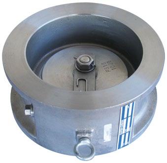
SW SERIES (Retainerless)
SW SERIES (Retainerless)
Pressure limits (CWP) SLP/SW series
ANSI 125 - 200 psi (1378 kpa)
ANSI 150 - 285 psi (1964 kpa)
ANSI 300 - 740 psi (5099 kpa)
ANSI 600 - 1480 psi (10197 kpa)
ANSI 900 - 2220 psi (15296 kpa)
ANSI 1500 - 3705 psi (25527 kpa)
TABLE E - 200 psi (1378 kpa)
Temperature limits SLP/SW series
2.0 INSTALLATION
Piping should be properly aligned and supported to reduce mechanical loading on the end connections.
Acceptable
Australian Pipeline Valve - Installation, Operation and Maintenance Manual 7 WAFER PATTERN CHECK VALVES - ‘SLP’ & ‘SW’ STYLE
ORIENTATION & FLOW DIRECTION
positions DIAGRAM 1 Normal Flow OK Note Hinge Position OK OK Note Hinge Position OK Norma Flow OK OK Avoid these positions Normal Flow NO Normal Flow NO NO NO NO
NBR seat Viton seat Metal seat 80ºC 200ºC 400ºC
Install valve in system using proper size and type mating flanges and appropriate gaskets (for FF or RF) or ring joint gasket (for RTJ). Observe the following precautions:
Do not install SLP/SW series wafer check valves directly against another valve whereby the check valve discharges downstream directly into another valve.
Do not install the valve whereby it directly discharges downstream into a tee or elbow fitting. Refer Diagram 1.
SLP/SW check valves are not suitable for vertical downflow installations.
2.1 INSTALLATION POSITIONS
Check valves are unidirectional and have the direction of flow indicated on the valve body. Supercheck single flap check valves are recommended for use only in horizontal lines and vertical lines for upwards flow only.
2.2 PREPARATION FOR INSTALLATION
• Remove protective end caps or plugs and inspect valve ends for damage to flange faces.
• Thoroughly clean adjacent piping system to remove any foreign material that could cause damage to seating surfaces during valve operation.
• Verify that the space available for installation is adequate to allow the valve to be installed.
2.3 END CONNECTIONS
2.3.1 Flanged Ends
Check to see that mating flanges are dimensionally compatible with the flanges on the valve body and ensure sealing surfaces are free of debris.
Install the correct studs and nuts for the application and place the gasket between the flange facings.
2.4 CLEANING
Stud nuts should be tightened in an opposing criss-cross pattern in equal increments to ensure even gasket compression. See Diagram 4.
Before installation, wash off any rust proofing solution coating with kerosene, or any hydrocarbon solvent product. Valve plate (flap) should be checked to ensure it is free.
2.5 DIRECTION OF FLOW
The direction of flow in the line should coincide with the flow direction indicated by the cast ‘arrow’ on the body of the valve.
VALVES - ‘SLP’ & ‘SW’ STYLE Australian Pipeline Valve - Installation, Operation and Maintenance Manual 8
WAFER PATTERN CHECK
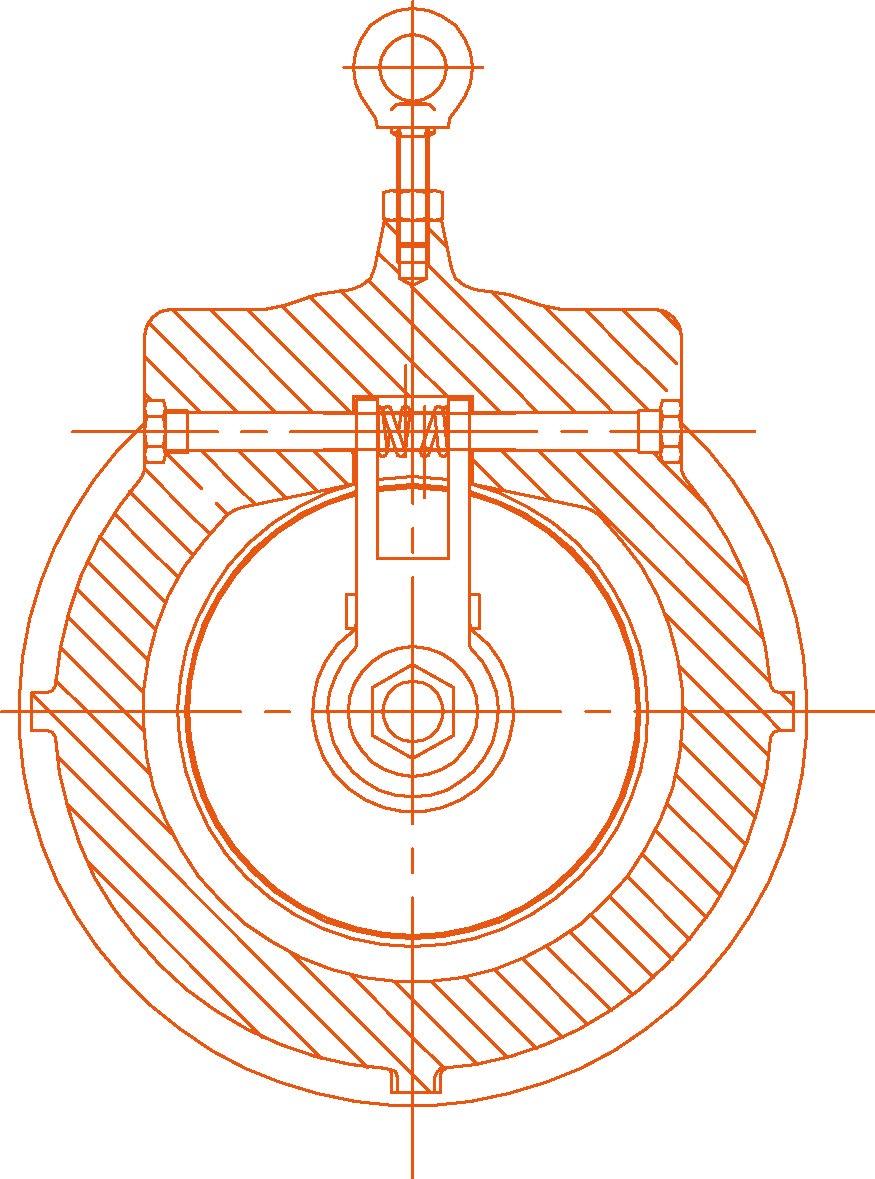
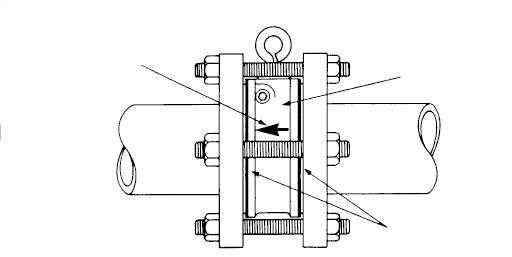
2.6 HORIZONTAL PIPING
Insert valve into pipeline only in the upright position for horizontal service. Install the valve as shown below so the flap hinge is at the top of the valve and is centred. Where provided, the lifting lug can serve as a guide. For SLP series the side pin retainer can also be used as a guide. For vertical services the valve must be used for upward flow only, refer to the arrow on the valve body indicating direction of flow, refer Diagram 1. DIAGRAM
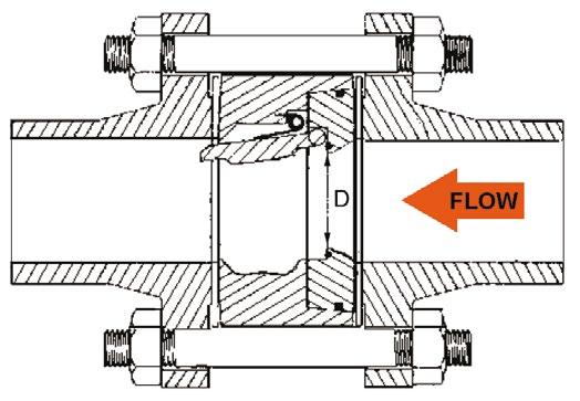
2.7 DISTANCE BETWEEN SINGLE FLAP CHECK VALVE AND A BUTTERFLY VALVE
If you attach another valve to the outlet side of the Supercheck valve, ensure that there is enough distance between two valves so that the plate of the Supercheck check valve does not touch the disc of the other valve in the open position. For separating other valves such as butterfly valves, a spacer spool may be required to stop the disc interfering with the check valve flap.
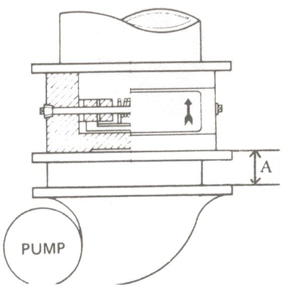
2.8 ORIENTATION OF SINGLE FLAP WAFER CHECK VALVE TO PUMP DISCHARGE
When mounting the Supercheck valve near a pump, as indicated on Diagram 3, position so that the flow of the pump meets evenly with the valve. The hinge pin of the Supercheck valve should be at right angles to the pump shaft. Ideally, for maximum service life keep distance ‘A’ more than 6 times the diameter of the pipe. For higher pressure the distance should be further away. However, SLP/SW series check valves should not be used in severe pulsating services such as reciprocating compressor discharges. Install check valves downstream of any pulsation dampeners or silencers in any system. Consult Diagram 1 for orientation positions. DIAGRAM
Australian Pipeline Valve - Installation, Operation and Maintenance Manual 9 WAFER PATTERN CHECK VALVES - ‘SLP’ & ‘SW’ STYLE
2 DIAGRAM 2A
3 PUMP A Check valve Gaskets Arrow indicating flow direction
Wafer check valves are designed for steady flow conditions and are not recommended for use near reciprocating pumps, but especially compressors, any pulsating devices or other types of physical/thermal shock-load applications. In this type of application, the check valve will not perform efficiently and will ultimately fail.
2.9 GASKETS
The opening end of the outlet side of Single Flap Check valve is manufactured larger than the internal diameter of the pipe. Use a gasket that is either the same internal diameter of the Uni-Check outlet, or slightly larger. Most common spiral wound or CNAF pipe gaskets will fit, providing they are the same corresponding flange class rating as the valve it’s specified to. CNAF gaskets are only suitable up to 1400 kPa (200 PSI). Ring joint gaskets are frequently specified for class 900 to 2500. The recommended tightening sequence is shown below in Diagram 4. Tighten in numerical order, gradually increasing torque with each sequence.
2.10 POST-INSTALLATION PROCEDURES
After installation, the line should be cleaned by flushing to remove any foreign material. When caustics are to be used to flush the line, additional flushing with clean water is required. The valve should be opened and closed after installation to ensure proper operating function. With the line pressurised, check the valve end connections and any body plugs for leaks.
3.0 OPERATION
The check valve operation is automatic and requires no assistance. When the flow exerts sufficient pressure against the disc to overcome the disc’s weight, the disc allows the flow to continue through the piping system. As pressure decreases, the disc lowers until it’s own weight forces it to seat. This prevents the possibility of a reversal in the flow. Metal seated check valves are not zero leak devices
WAFER PATTERN CHECK VALVES - ‘SLP’ & ‘SW’ STYLE Australian Pipeline Valve - Installation, Operation and Maintenance Manual 10
3 8 2 5 4 7 1 6 ORDER OF TIGHTENING BOLTS DIAGRAM 4
and may “seep” in service. This type of valve should always be backed up with an isolation valve. Even soft seated valves require a small amount of back pressure before a seal is effected. Similarly, to open the valve the ‘cracking pressure’ will depend on the spring tension. Low cracking pressure springs are available.
4.0 MAINTENANCE
No periodic maintenance is necessary, except in the case of the SLP series where external over-rides, dampners, counterweights, etc., may be fitted which require an external gland packing. In this case the packing gland may need tightening (unless it is O-ring style).
5.0 REPAIRS
Proper safety equipment and apparel should be worn when preparing to service a valve. Observe the general safety warnings throughout this catalogue and consult your safety manager and plant manager.
5.1 REPAIR INSTRUCTIONS
Due to the relatively low replacement cost of small diameter standard iron or carbon steel valves especially under 200 NB (8”), it is usually less expensive to replace the complete valve than to have maintenance personnel effect repairs.
Flange face gasket sealing surfaces should be scraped clean (avoid radial marks).
5.2 REMOVING VALVE FROM PIPELINE
Only one half of the stud bolts need to be removed (others can just be loosened) when removing the uni-flap from the line. Of course for flanged and lugged valves, all bolts must be removed.
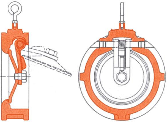
5.3 DISASSEMBLY SLP SERIES
First ensure all fluids and gases are released from valve before commencing. Protective splash proof and safety eye goggles should be worn. Unscrew the hinge pin retainers (8) from the body (1). To remove hinge pin (3) maintain pressure on the spring (5) and withdraw hinge pin (3), pulling it through disc (2), spring (5), and bushings (6). Take careful note of the spring position then disassemble and remove spring (5), body bushings (6) and disc (2). The seat is integral. Metal seats are machined finished and can be re lapped or re-metalised. Seat material can be the same as body or overlaid with 316 or stellite. Soft seat inserts are pressure and heat bonded into the body (or in some sizes the flap) and must be returned to Australian Pipeline Valve for repair where viable. Once disassembly is complete, inspect parts for damage and order replacement parts as required. Use new replacement parts, as required. Use a liberal amount of general purpose grease on seals and machined mating surfaces.
Australian Pipeline Valve - Installation, Operation and Maintenance Manual 11 WAFER PATTERN CHECK VALVES - ‘SLP’ & ‘SW’ STYLE
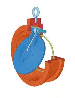
Important see Diagram 5 and caution note below about guarding the spring during disassembly to prevent eye damage. Refer to exploded view in Appendix.
5.4 ASSEMBLY SLP SERIES
a) Lay the body (1) down, with ‘downstream’ side of the body facing upward. Lay disc (2) inside the body (1). Slide hinge pin (3) into the body through the bushings (6) (where fitted) the spring (5) and disc (2). Refer paragraph b) below on energising spring into the body. Reinsert disc into body cavity with shaft holes inline with side shaft port. Slide shaft into the body through shaft bearing on one side. Continue sliding shaft through disc, disc spring and remaining bushing. Check the disc (2) and bushings for end play. If body plate is severely worn it should be replaced.
b) Wind the spring (5) 180° in a clockwise direction. Place the wound spring (5) in position between the disc hinge lugs ensuring the long convex side of the spring’s leg is against the disc, the other end must be energised against the wall of the valve as per the Diagram 4. Different sizes and classes may have different spring configurations. While maintaining pressure on the spring (5), insert the hinge pin (3) into the body (1) passing it through the bushings (6) (where required), disc (2) and spring (5) as detailed above in paragraph a).
c) Teflon tape the threads of the hinge pin retainer, and screw the hinge pin retainers (8) into the body (1).
After repair, the valve should be retested as per API 598 or applicable standard.
For SLP and SW series: under no circumstances wind springs to gain a higher or lower torsional load. Special high and low torque springs are available for this purpose. Before attempting shaft extraction, be sure to press hand over the disc spring (see Diagram 5). Failure to do this may result in personal injury due to the spring “launching” itself unexpectedly once the shaft is pulled free of it. Always wear protective eyewear.
WAFER PATTERN CHECK VALVES - ‘SLP’ & ‘SW’ STYLE Australian Pipeline Valve - Installation, Operation and Maintenance Manual 12
DIAGRAM 5
5.5 DISASSEMBLY SW SERIES
First ensure all fluids and gases are released from valve before commencing. Protective splash proof and safety eye goggles should be worn. Unscrew the grub screws (9) from the body (1). Take careful note of the spring position. Then slide out both inserts (6) containing the complete cartridge assembly which includes the hinge pin (3) disc (2) spring (5) and washers (7). Then first remove both inserts (6) to then slide out hinge pin (3) maintain pressure on the spring (5) and withdraw hinge pin (3). Pulling it through disc (2), spring (5), and washers (7). The seat is integral. Metal seats are machined finished and can be re lapped for re-metalised. Seat material can be the same as body or overlaid with 316 or stellite. Soft seat inserts are heat bonded into the body (or in some sizes the flaps) and must be returned to Australian Pipeline Valve for repair where viable. Once disassembly is complete inspect parts for damage and order replacement parts as required. Use new replacement parts, as required. Use a liberal amount of general purpose grease on seals and machined mating surfaces.
Important, see Diagram 5 (SLP type shown but guard spring in the same manner) and caution note on previous page about guarding spring during disassembly to prevent eye damage. Refer to exploded view in Appendix.
5.6 ASSEMBLY SW SERIES
a) Lay the body (1) down, with ‘downstream’ side of the body facing upward. Reassemble in reverse order to 5.5 above. Slide the hinge pin (3) through the first washer (7) then into the first disc eyelet (2) then through the spring (or springs) (5) and then through the other disc (2) eyelet and washer (7). Different sizes and classes may have slightly different spring configurations. Always fit a new spring if the spring becomes stretched. Refer paragraph b) below on energising springs. Check the disc (2) and washers for end play. If body plate is severely worn, it should be replaced. Attach both inserts (6) to hinge pin (3) and then reinsert complete cartridge unit into the body (1). Then screw both grub screws (9) into place, ensuring the inserts and screws are flush with the gasket face area.
b) Wind the springs (5) 180° in a clockwise direction. Place the wound springs (5) in position between the disc hinge lugs ensuring the convex side of the spring’s leg is against the disc. While maintaining pressure on the spring (5), insert the hinge pin (3) into the body (1) passing it through the washers (7), disc (2) and springs (5) as detailed above in paragraph a).
After repair, the valve should be retested as per API 598 or applicable standard.
Australian Pipeline Valve - Installation, Operation and Maintenance Manual 13 WAFER PATTERN CHECK VALVES - ‘SLP’ & ‘SW’ STYLE
APPENDIX
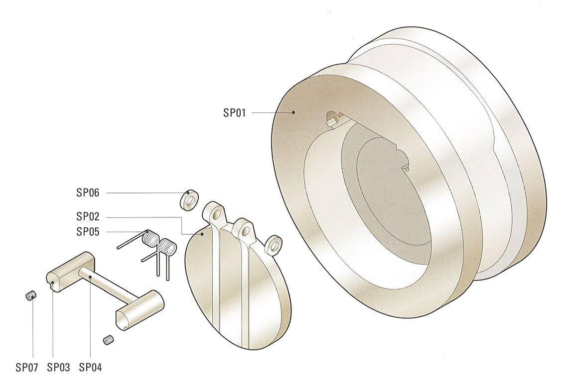
EXPLODED VIEW SLP SERIES
Indicative design only, refer to as-built drawing. Design varies according to size, class & trim.
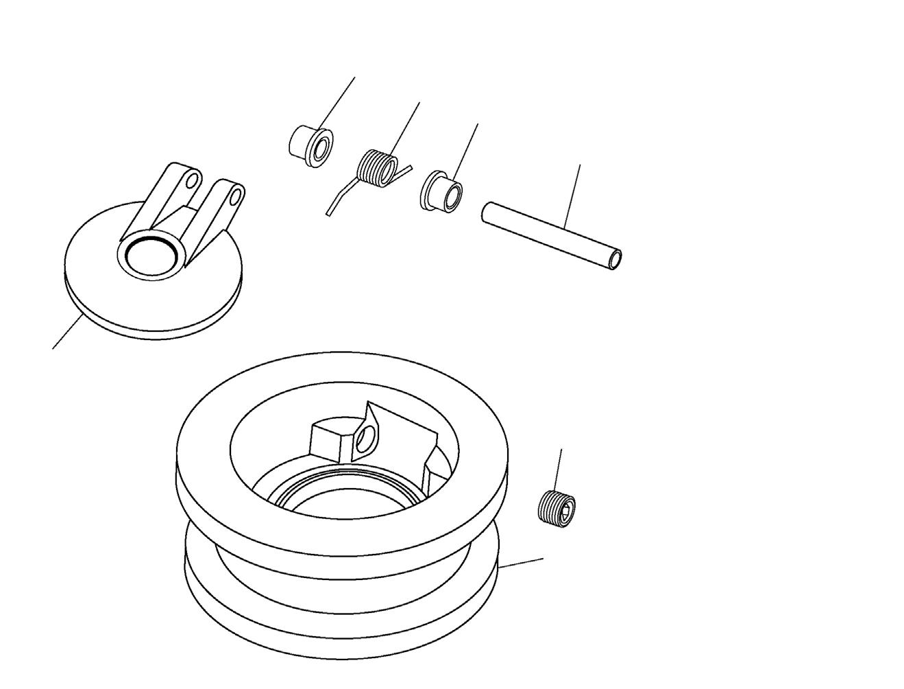
EXPLODED VIEW SW SERIES
Indicative design only, refer to as-built drawing. Design varies according to size, class & trim.
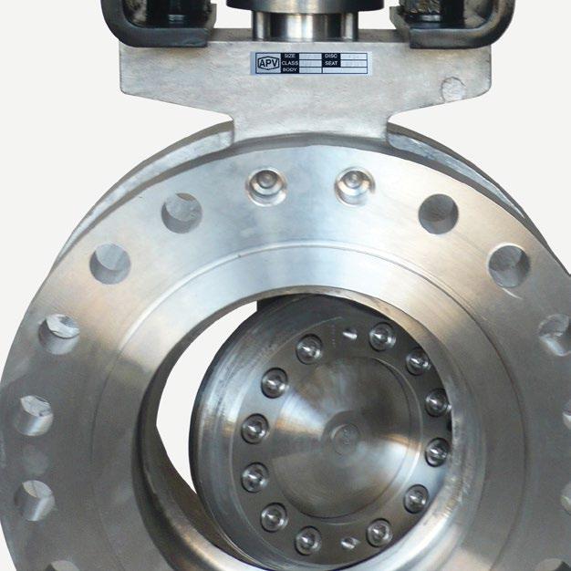
Resilient, Soft Seat coupled with precision machined sealing surfaces ensure a bubble tight seal (Metal seat available)
WAFER PATTERN CHECK VALVES - ‘SLP’ & ‘SW’ STYLE Australian Pipeline Valve - Installation, Operation and Maintenance Manual 14
RESILIENT O-RING SEAT OPTION SLP/SW 1 BODY 2 DISC *1 3 HINGE PI N 4 SEAT (INTEGRAL) 5 SPRING 6 BUSHINGS *2 8 HINGE PIN RETAINERS 9 EYE BOLT SLP STYLE COMPONENTS *1 Integral version shown, some sizes have separate hinge arm & disc. *2 Where applicable. 1 BODY 2 DISC 3 HINGE PI N 4 SEAT (INTEGRAL) 5 SPRING 6 INSERT 7 WASHERS 9 SET SCREW SW STYLE COMPONENTS 1 7 2 5 3 6 9 4 DIAGRAM 7 6 5 6 3 8 4 1 2 DIAGRAM 6
a Gas test not performed as standard on cast iron body valves and is not required as per API 598. API598 does not require gas test on steel valves but APV performs it
b 5.5 bar minimum test pressure. (Higher test pressure may be required to energise resilient seat in high pressure classes/larger sizes).
c Since API 598 does not specify a leakage rate for resilient seated check valves, many manufacturers use the metal seated check valve leakage rate. However, APV demands as close as possible to tight shut off as per API 598 resilient seated (ISO 5208-A) Note in higher classes in smaller sizes and all classes in larger sizes, 3 up to 10 water drips a minute is accepted.
d For check valves, gas test is not required as per API 598, but APV does perform it.
1cc = 16 drops, 1ml = 16 drops
Australian Pipeline Valve - Installation, Operation and Maintenance Manual 15 WAFER PATTERN CHECK VALVES - ‘SLP’ & ‘SW’ STYLE TABLE 1 Wafer Check Valve Standard APV Allowable Leakage Rates for Closure (Seat) Tests API 598 VALVE SIZE METAL SEATED WAFER CHECK VALVES SOFT SEATED WAFER CHECK VALVES NB NPS LIQUID TEST (cc/min) GAS TEST (bubbles/min) LIQUID TEST (cc/min) GAS TEST a (bubbles/min) APV API 598 API 598 APV API 598 APV a API 598 ≤50 ≤2 3 6 Not required per API598 d 0 c Not specified c 2 b Not required per API598 d 65 2.5 3.75 7.5 Not required per API598 d 0 c Not specified c 2 b Not required per API598 d 80 3 4.0 9 Not required per API598 d 0 c Not specified c 2 b Not required per API598 d 100 4 6.0 12 Not required per API598 d 0 c Not specified c 2 b Not required per API598 d 125 5 7.5 15 Not required per API598 d 0 c Not specified c 2 b Not required per API598 d 150 6 9.0 18 Not required per API598 d 0 c Not specified c 2 b Not required per API598 d 200 8 12.0 24 Not required per API598 d 0 c Not specified c 2 b Not required per API598 d 250 10 15.0 30 Not required per API598 d 0 c Not specified c 3 b Not required per API598 d 300 12 18.0 36 Not required per API598 d 0 c Not specified c 3 b Not required per API598 d 350 14 21.0 42 Not required per API598 d 0 c Not specified c 4 b Not required per API598 d 400 16 24.0 48 Not required per API598 d 0 c Not specified c 4 b Not required per API598 d 450 18 27.0 54 Not required per API598 d 0 c Not specified c 5 b Not required per API598 d 500 20 30.0 60 Not required per API598 d 0 c Not specified c 6 b Not required per API598 d 600 24 36.0 72 Not required per API598 d 0 c Not specified c 7 b Not required per API598 d
WARRANTY
1. LIMITED WARRANTY: Subject to the limitations expressed herein, Seller warrants that products manufactured by Seller shall be free from defects in design, material and workmanship under normal use for a period of one (1) year from installation but in no case shall the warranty period extend longer than eighteen months from the date of sale. This warranty is void for any damage caused by misuse, abuse, neglect, acts of God, or improper installation. For the purpose of this section, “Normal Use” means in strict accordance with the installation, operation and maintenance manual. The warranty for all other products is provided by the original equipment manufacturer.
2. REMEDIES: Seller shall repair or replace, at its option, any non-conforming or otherwise defective product, upon receipt of notice from Buyer during the Manufacturer’s warranty period at no additional charge. SELLER HEREBY DISCLAIMS ALL OTHER EXPRESSED OR IMPLIED WARRANTIES, INCLUDING, WITHOUT LIMITATION, ALL IMPLIED WARRANTIES OF MERCHANTABILITY AND FITNESS OR FITNESS FOR A PARTICULAR PURPOSE.
3. LIMITATION OF LIABILITY: UNDER NO CIRCUMSTANCES SHALL EITHER PARTY BE LIABLE TO THE OTHER FOR INCIDENTAL, PUNITIVE, SPECIAL OR CONSEQUENTIAL DAMAGES OF ANY KIND. BUYER HEREBY ACKNOWLEDGES AND AGREES THAT UNDER NO CIRCUMSTANCES, AND IN NO EVENT, SHALL SELLER’S LIABILITY, IF ANY, EXCEED THE NET SALES PRICE OF THE DEFECTIVE PRODUCT(S) PURCHASED DURING THE PREVIOUS CONTRACT YEAR.
4. LABOR ALLOWANCE: Seller makes NO ADDITIONAL ALLOWANCE FOR THE LABOR OR EXPENSE OF REPAIRING OR REPLACING DEFECTIVE PRODUCTS OR WORKMANSHIP OR DAMAGE RESULTING FROM THE SAME.
5. RECOMMENDATIONS BY SELLER: Seller may assist Buyer in selection decisions by providing information regarding products that it manufacturers and those manufactured by others. However, Buyer acknowledges that Buyer ultimately chooses the product’s suitability for its particular use, as normally signified by the signature of Buyer’s technical representative. Any recommendations made by Seller concerning the use, design, application or operation of the products shall not be construed as representations or warranties, expressed or implied. Failure by Seller to make recommendations or give advice to Buyer shall not impose any liability upon Seller.
6. EXCUSED PERFORMANCE: Seller will make a good faith effort to complete delivery of the products as indicated by Seller in writing, but Seller assumes no responsibility or liability and will accept no back-charge for loss or damage due to delay or inability to deliver, caused by acts of God, war, labor difficulties, accidents, inability to obtain materials, delays of carriers, contractors or suppliers or any other causes of any kind whatever beyond the control of Seller. Under no circumstances shall Seller be liable for any special, consequential, incidental, or indirect damages, losses, or expense (whether or not based on negligence) arising directly or indirectly from delays or failure to give notice of delay.
WAFER PATTERN CHECK VALVES - ‘SLP’ & ‘SW’ STYLE Australian Pipeline Valve - Installation, Operation and Maintenance Manual 16
Australian Pipeline Valve - Installation, Operation and Maintenance Manual NOTES

www.australianpipelinevalve.com.au AUSTRALIAN PIPELINE VALVE® HEAD OFFICE 70-78 Stanbel Road Salisbury Plain South Australia 5109 Telephone +61 (0)8 8285 003 email: admin@australianpipelinevalve.com.au If you have any requirements in the field of valves, please contact us for a prompt response. Continuous development of Australian Pipeline Valve products may necessitate changes in the design or manufacture process. Australian Pipeline Valve reserves the right to effect any such changes without prior notice. © Australian Pipeline Valve 1990 - 2024 Edition LOCAL DISTRIBUTOR/AGENT IOM Supercheck Checkwafer SLP SW