INTRODUCTION
Note
We do recommend however, that this entire document be read prior to proceeding with any installation or repair. Australian Pipeline Valve and it’s parent company take no responsibility for damage or injury to people, property or equipment. It is the sole responsibility of the user to ensure only specially trained valve repair experts perform repairs under the supervision of a qualified supervisor.
RESPONSIBILITY FOR VALVE APPLICATION
Do not use any valve in application where either the pressure or temperature is higher than the allowable working values. Also, valves should not be used in service media if not compatible with the valve material of construction, as this will cause chemical attacks.
RECEIVING INSPECTION AND HANDLING
The End User is advised that misapplication of the product may result in injuries or property damage. A selection consistent with the particular performance requirements is important for proper application and is the sole responsibility of the end user.
SAFETY INFORMATION
To avoid injury, never attempt disassembly while there are pressures either upstream or downstream. Even when replacing packing rings, caution is necessary to avoid possible injury. Disassemble with caution in the event all pressures are not relieved.
• A valve is a pressurised device containing energised fluids and should be handled with appropriate care.
• Valve surface temperature may be dangerously too hot or too cold for skin contact.
• Upon disassembly, attention should be paid to the possibility of releasing dangerous and or ignitable accumulated fluids.
• Adequate ventilation should be available for service.
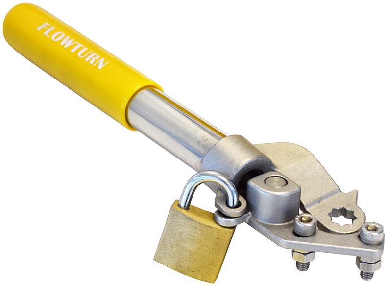
SPRING RETURN HANDLE Australian Pipeline Valve - Installation, Operation and Maintenance Manual 2
Note
Personal injury may result from sudden release of any process pressure. APV recommends the use of protective clothing, gloves and eye wear when performing any installation or maintenance.
Isolate the valve from the system and relieve pressure prior to performing maintenance.
Disconnect any operating line providing air pressure, control signals or electrical power to actuators.
Note
Potential HIGH PRESSURE vessel - be aware of high-pressure hazards associated with the attached valve or other actuated device when installing or performing maintenance on the operator. Do not remove the operator bolts from the valve or actuated device unless the valve or device stem is secured or there is no pressure in the line.
For maintenance and/or disassembly of the operator when installed on the valve, ensure that the operator is not under thrust or torque load. If the valve must be left in service, the valve stem must be locked in such a way as to prevent any movement of the valve stem.
Do not manually operate the operator with devices other than the installed lever. Using force beyond the ratings of the operator and/or using additive force devices such as cheater bars, wheel wrenches, pipe wrenches, or other devices on the operator lever may cause serious personal injury and/or damage to the operator and valve.
Do not exceed any design limitations or make modifications to this equipment without first consulting us.
Use of the product must be suspended any time it fails to operate properly. Do not use replacement parts that are not genuine APV-Flowturn, as serious personal injury and/or damage to the operator and valve may result.
1.0 INSTALLATION
Flowturn Spring Return Handles have been designed and engineered to provide long lasting and troublefree service when used in accordance with the instructions and specifications herein.
The angle of rotation is set to 90 degrees and is not adjustable.
1.1 SAFETY PRECAUTIONS
It is suggested that the following safety precautions should be taken when handling valves:
Australian Pipeline Valve - Installation, Operation and Maintenance Manual 3 SPRING RETURN HANDLE
SPRING RETURN HANDLE
1. Always wear safety glasses
2. Always wear gloves
Ensure that all applicable industry specifications and standards for safe installation are followed. Failure to correctly install this product may result in injuries or property.
For any questions please contact Australian Pipeline Valve.
1.2 COMPONENTS
Some valve series require additional brackets and couplers that are not shown below. For further information contact Australian Pipeline Valve.
Australian Pipeline Valve - Installation, Operation and Maintenance Manual 4
Note
No. Part Name Material Qty 1 Handle head CF8 1 2 Anchor CF8 1 3 Anchor screw SS304 1 4 Spring rod SS304 1 4a Spring rod anchor SS304 1 5 Spring SS301 1 6 Handle extension SS304 1 7 Sleeve PVC 1 8 Washer SS304 2 9 Hex nut SS304 2 10 Socket head screws SS304 2 11 Washer SS304 1 12 Nut SS304 1 MODEL S71-504 ~ 571-509 SS304 SWP SS304 SS304 BOLT 7 9 8 6 WASHER SPRING HANDEL HEX SS304 VINYL SS304 NUT 10 12 11 HANDL E SL EEVE HA NDLE CF8 SS304 MATERIAL SS304 CF8 SS304 NO 1 2 HANDEL GL AND PART NA ME HANDLE BOLT NUT 3 5 4 WASHER HA NDLE 6 7 SS304 SWP SS304 SS304 BOLT 7 9 8 6 WASHER SPRING HANDEL HEX SS304 VINYL SS304 NUT 10 12 11 HANDL E SL EEVE HA NDLE CF8 SS304 MATERIAL SS304 CF8 SS304 NO 1 2 HANDEL GL AND PART NA ME HANDLE BOLT NUT 3 5 4 WASHER HA NDLE 1 1 1 1 2 1 1 Q'TY 1 2 1 1 1 12 11 2 10 1 10 SS304 SWP SS304 SS304 BOLT 7 9 8 6 WASHER SPRING HANDEL HEX SS304 VINYL SS304 NUT 10 12 11 HANDL E SL EEVE HA NDLE CF8 SS304 MATERIAL SS304 CF8 SS304 NO 1 2 HANDEL GL AND PART NA ME HANDLE BOLT NUT 3 5 4 WASHER HA NDLE 1 1 1 1 2 1 1 Q'TY 1 2 1 1 1 3 4A 5 9 8 4 10


Australian Pipeline Valve - Installation, Operation and Maintenance Manual 5 SPRING RETURN HANDLE MODEL S71-504 ~ S71-509 2 1 3 4A 5 6 7 8 9 10 11 12 4 CLOSED POSITION TABLE 1 Kit Part No. M** (Max) L J* D (ISO 5211) Torque ETC Torque BTC S71-504-00 20 170 9 F03/F04 15 Nm 30 Nm S71-507-00 40 207 9 F03/F04 20 Nm 45 Nm S71-507-01 45 220 11 F04/F05 20 Nm 45 Nm S71-508-00 65 275 11 F04/F05 30 Nm 60 Nm S71-508-01 65 280 14 F05/F07 30 Nm 63 Nm S71-509-01 190 436 14 F04/F05 55 Nm 75 Nm S71-509-00 190 436 14 F05/F07 56 Nm 75 Nm CLOSED POSITION OPEN POSITION 2 3 4 5 6 7 8 9 1 M H H d1 d2 D2 D1 4A Maximum bore ** Maximum spring tightening distance
Deadman valves are best suited to direct mount valves, or can be flush mounted on a direct mount plate fastened to the valve, recessed to bridge the gland nut where feasable. The use of a bracket & adaptor will result in torque loss and will alter the parallel plane required by deadman levers to avoid the spring rod interferring with the housing. Where a bracket & adaptor is required, APV has other models of deadman levers available.
1.3 INSTALLATION AND ASSEMBLY PROCEDURE
It is important to first determine if the Spring Return Handle (SRH) is required to function as spring open or spring closed. When supplied fitted to a valve, all levers are set to close and spring tensions are preset for the valve. However, procedure to reset is as follows:-
1. Remove the factory standard handle (where applicable) by loosening and removing the handle nut (12) on the top side of the handle and remove any additional lock washers (11) under the nut.
a. Be sure to set the nut and any washers aside as they may be required for later installation of the Spring Return Handle.
b. It is important to ensure that none of the other components on the stem under the handle get removed or fall off. This includes any stem nut securing devices. Failure to ensure these components do not come off can result in the stem nut coming loose and the valve leaking.
2. Firmly attach handle head (item 1) to the valve using the two anchor screws provided (item 3).
a. For some valve series a separate adaptor bracket is required to be attached to the valve mounting pad between the mounting pad and handle gland interface.
3. Attach handle anchor (item 2) over the stem and secure it using the handle nut. If no additional handle nut is provided you will use the handle nut and lock washers removed in step one.
a. Make sure the stop tabs are correctly positioned for the required spring back position (open or closed).
b. For some valve series a separate coupler is required between the valve stem and handle interface.
4. Insert the spring rod (item 4) binder nut end first through the handle opening and secure it to the handle head (item 1) using the anchor screw (item 3) through the binder nut (item 4a) into the centre threaded hole in the handle head (item 1).
5. Apply a high quality anti seize lubricant to the spring rod (item 4).
6. Slide the spring coil (item 5) over the spring rod (item 4).
7. Slide the flat washer (item 8) onto the spring rod (item 4).
8. If fitted to valve, the tensions are preset. Thread on the hex nuts (item 9) onto the spring rod (item 4) and thread down to tighten the spring until the desired closing force is used. Do not over tighten. If torque is insufficient use a larger lever. Generally even loose handles are factory preset but slight adjustments are possible.
SPRING RETURN HANDLE Australian Pipeline Valve - Installation, Operation and Maintenance Manual 6
1. Tensions required depend on spring fitted. Do not over tighten. Additional adjusting may be required to ensure proper operation of the Spring Return Handle.
2. Use caution when tightening the hex nut as the spring coil (item 5) is under increasing pressure.
9. Thread the second hex nut (item 9) up to the first hex nut and tighten the two together to prevent any accidental loosening of the nuts.
10. Slide the handle sleeve (item 6) over the spring rod (item 4) and the spring coil (item 5) and fully thread it into the anchor handle (item 2).
11. Verify the handle operates freely and correctly by rotating it several times and making any adjustments required.
1.4 INCREASING THE SPRING RETURN FORCE
1. With the handle still assembled to the valve remove the handle sleeve (item 6) by fully unthreading it from the handle (item 2).
2. Slightly loosen the hex nut (item 9) closest to the free end of the spring rod (item 4) to release any force that is on the first hex nut (item 9).
3. Tighten down the first hex nut (item 9) 5mm and then thread the second hex nut (item 9) down up to the first hex nut and tighten the two together to prevent any accidental loosening of the nuts.
a. Use caution when tightening the hex nuts as the spring coil (item 5) is under increasing pressure.
4. Slide the handle sleeve (item 6) over the spring rod (item 4) and spring coil (item 5) and fully thread it into the anchor handle (item 2).
5. Check to see that the handle operates freely and correctly by rotating it several times making sure the handle rotates the complete 90 degrees to fully spring open or closed, depending on how it is set up, while on the valve.
6. If the handle still does not fully spring open or closed, depending on how it is set up, repeat steps 1 - 5 of the Increasing the Spring Return Force section until the valve can fully spring open or closed freely on its own.
7. Do not tighten more than dimensions ‘M’ shown in table 1 to avoid damage to the unit.
Australian Pipeline Valve - Installation, Operation and Maintenance Manual 7 SPRING RETURN HANDLE
Note