www.australianpipelinevalve.com.au INSTALLATION, OPERATION & MAINTENANCE MANUAL
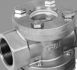
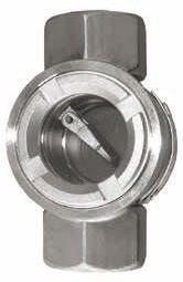
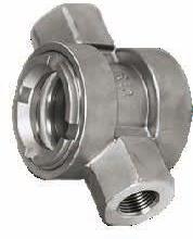
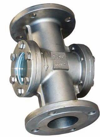
SIGHT GLASS SLSG SERIES
COMPLETE PRODUCT LINE
“Australian Pipeline Valve produces isolation, control and flow reversal protection products for severe and critical service media in utility, steam, pipelines, oil & gas and process industries. APV valves and pipeline products form the most competitive portfolio in the market.”
View our catalogues at www.australianpipelinevalve.com.au AUSTRALIAN PIPELINE VALVE BRAND RANGE - CATALOGUES APV FAMILY OF BRANDS RANGE - CATALOGUES
Oilfield Products Valves & Wellheads Gate, Globe & Check Valves - Forged Steel Plug Valves Lubricated, Sleeved & Lined Gate, Globe & Check Valves - Cast Steel Diamond Gear Gearboxes Flowturn Gate, Globe & Check Valves Flowturn Instrument Valves Flowturn Ball Valves Multiway & Deadman Flowturn Strainers & Sight Glasses Supercheck Wafer Check Valves Superseal Butterfly Valves Steamco Steam Valves Superseal Industrial Ball Valves TwinLok Tube Fittings Uniflo Check Valves
Actuators
Valves Floating & Trunnion Mounted Ball Valves Floating Small Bore Ball Valves Special Service Product Brochure Contact us for your local stockist/distributor
Torqturn
Ball
SIGHT GLASSES - SLSG SERIES INDEX Australian Pipeline Valve - Installation, Operation and Maintenance Manual 1 Introduction 2 Safety Information 3-4 1.0 Installation 5 1.1 Installation positions 5 1.2 Preparation for installation 5 1.3 Post-installation procedures 5 2.0 Handling 5-6 3.0 Operation 6 4.0 Maintenance During Operation 6-7 4.1 Leaking between sight glass body and sight glass cap 6-7 5.0 Disassembling Sight Glasses 7 6.0 Repair 7 6.1 Repairing the leak at the body-cap joint & replacing body gasket 7 7.0 Reassembly 8 8.0 Preventative Maintenance 8 9.0 Leakage Across Gasket 8 10.0 Major Maintenance 8-9 10.1 Gasket replacement 8 10.2 Sight Glass internals disassembly inspection repair 8-9 11.0 Pressure Temperature Rating 9 Appendix A - Bolting torque sequence 10 Appendix B - Drawings SLSG Series 11-14
INTRODUCTION
The majority of this information is common knowledge to experienced valve users. When properly installed in applications for which they were designed, Flowturn valves will give long reliable service. This instruction is only a guide for installation and operation on standard service and covers general maintenance and minor repairs. A professional APV approved valve engineering facility should be utilised for reconditioning or major repairs. Note
We do recommend however that this entire document be read prior to proceeding with any installation or repair. Australian Pipeline Valve and it’s parent company take no responsibility for damage or injury to people, property or equipment. It is the sole responsibility of the user to ensure only specially trained valve repair experts perform repairs under the supervision of a qualified supervisor.
RESPONSIBILITY FOR SIGHT GLASS APPLICATION
The User is responsible for ordering the correct valves. The user is responsible for ensuring APVFlowturn Valves are selected and installed in conformance with the current pressure rating and design temperature requirements. Prior to installation, the valves and nameplates should be checked for proper identification to ensure the valve is of the proper type, material and is of a suitable pressure class and temperature rating to satisfy the requirements of the service application.
Do not use sight glasses in applications where either the pressure or temperature is higher than the allowable working values. Also sight glasses should not be used in service media if not compatible with the sight glass material of construction, as this will cause chemical attacks, leakage, valve failure.
RECEIVING INSPECTION AND HANDLING
Valves should be inspected upon receipt to ensure:
- Conformance with all purchase order requirements.
- Correct type, pressure class, size, body and trim materials and end connections.
- Any damage caused during shipping and handling to end connections, hand wheel or stem.
The User is advised that specifying an incorrect valve for the application may result in injuries or property damage. Selecting the correct valve type, rating, material and connections, in conformance with the required performance requirements is important for proper application and is the sole responsibility of the user.
SIGHT GLASSES - SLSG SERIES Australian Pipeline Valve - Installation, Operation and Maintenance Manual 2
SAFETY INFORMATION
The following general safety information should be taken in account in addition to the specific warnings and cautions specified in this manual. They are recommended precautions that must be understood and applied during operation and maintenance of the equipment covered in this I.O.M.
To avoid injury, never attempt disassembly while there are pressures either upstream or downstream. Caution is necessary to avoid possible injury.
To prevent bending, damage, inefficient operation, or early maintenance problems, support piping on each side of the sight glass.
• A sight glass is a pressurised mechanism containing energised fluids under pressure and consequently should be handled with appropriate care.
• Valve surface temperature may be dangerously too hot or too cold for skin contact.
• Upon disassembly, attention should be paid to the possibility of releasing dangerous and or ignitable accumulated fluids.
• Ensure adequate ventilation is available for service.
This manual provides instructions for storing, general servicing, installation and removal of SLSG Series Sight Glasses.
APV and it’s resellers refuse any liability for damage to people, property or plant as well as loss of production and loss of income under any circumstances but especially if caused by: Incorrect installation or utilisation of the valve or if the valve installed is not fit for intended purpose. It is the sole responsibility of the user to ensure the valve type and materials are correctly specified.
GLASSES - SLSG SERIES Australian Pipeline Valve - Installation, Operation and Maintenance Manual 3
SIGHT
DURING OPERATION TAKE INTO ACCOUNT THE FOLLOWING WARNINGS:
a- Graphite body gaskets are very brittle, any impacting, twisting or bending should be avoided. PTFE gaskets must not have any scrathes to surface.
b- The sight glass’s internal parts such as flow indicator, pin & gasket shall be handled with care.
c- All tools and equipment for handling the internal parts shall be soft coated.
d- Valves can be fitted with gaskets or seals in PTFE, Buna, EPDM, NBR, Viton, etc., hence chemicals or high temperatures will damage sealing components.
For all operations make reference to position number on part list of the applicable drawing listed.
Bonnet seal could result in personal injury. Bonnet is tightened prior to shipping but may require replacement seal or tightening to meet specific service conditions.
Personal injury may result from sudden release of any process pressure. APV recommends the use of protective clothing, gloves and eye wear when performing any installation or maintenance.
Isolate the sight glass from the system and relieve pressure prior to performing maintenance.
Disconnect any operating line providing air pressure, control signals or electrical power to actuators.
If a gasket seal is disturbed while removing or adjusting gasketed parts, APV recommends installing a new gasket while reassembling. A proper seal is required to ensure optimum operation.
SIGHT GLASSES - SLSG SERIES Australian Pipeline Valve - Installation, Operation and Maintenance Manual 4
1.0 INSTALLATION
Piping should be properly aligned and supported to reduce mechanical loading on the end connections.
1.1 INSTALLATION POSITIONS
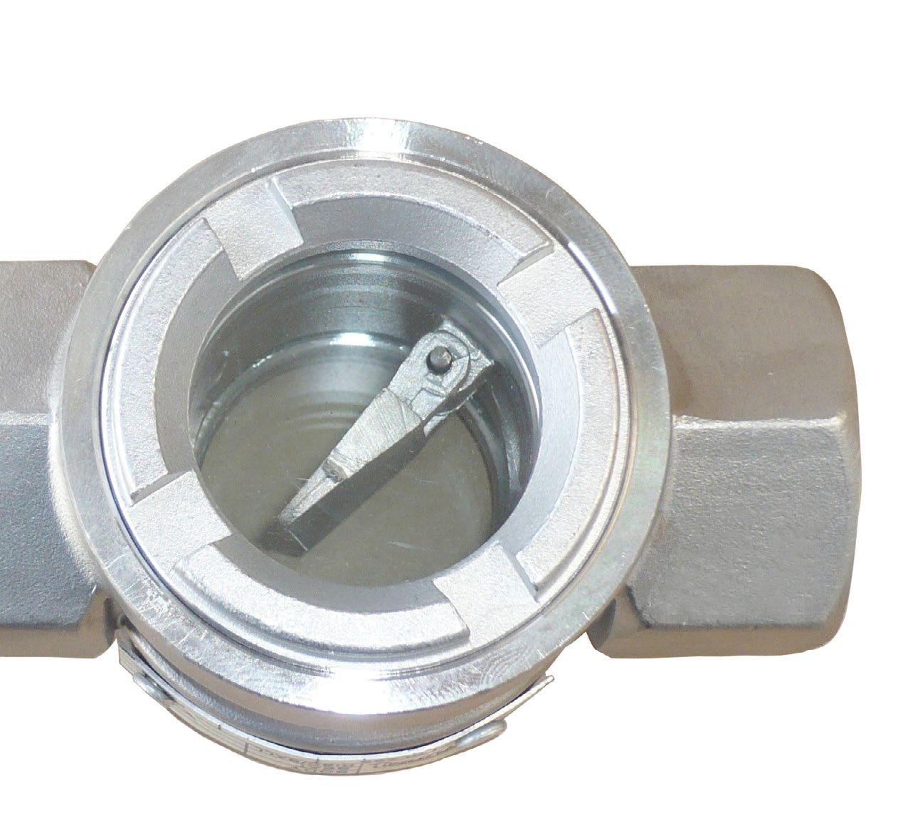
Sight valves fitted with flow indicators are uni-directional, the direction of flow will be indicated on the valve body. Sight glasses with indicators should be used for horizontal lines with the bonnet facing up, and vertical lines where the direction of flow as indicated on the valve body is upwards.
1.2 PREPARATION FOR INSTALLATION
• Remove protective end caps or plugs and inspect valve ends for damage to flange faces.
• Thoroughly clean adjacent piping system to remove any foreign material that could cause damage to seating surfaces during valve operation.
• Verify that the space available for installation is adequate to allow the valve to be installed and to be operated.
1.3 POST-INSTALLATION PROCEDURES
After installation, the line should be cleaned by flushing to remove any foreign material. When caustics are to be used to flush the line, additional flushing with clean water is required. The valve should be tested after installation to ensure proper operating function.
With the line pressurised, check the valve end connections, body to bonnet/cover joints and plugs for leaks.
2.0 HANDLING
1. Take care in handling sight glasses especially the sealing faces.
2. Make sure that piping and equipment is clean of dust, rust and pipeline scale. Clean all adjoining pipe and fittings. Remove end protector covers from the valves immediately prior to installation. Blow compressed air inside the valves to remove residual dust, dirt, etc., from inside the sight glasses as this could hamper the valves functioning and could also damage the seats.
3. Make bonnet joints tight but do not overstress them. Always tighten in a diagonal pattern, gradually increasing torque settings. Refer to Appendix A, Diagram 1.
4. Install sight glasses in the connecting piping so that the arrow mark on the valve body coincides with the flow direction in the pipe.
5. After installation it is advisable to once again flush the piping. Check carefully for visible leaks if any and tighten bonnet nuts accordingly.
SIGHT GLASSES - SLSG SERIES Australian Pipeline Valve - Installation, Operation and Maintenance Manual 5
6. If the leakage still persists change the bonnet gasket.
Proper safety equipment and apparel should be worn when preparing to service the sight glass.
3.0 OPERATION
The sight glass operation is automatic and requires no assistance. When the flow exerts sufficient pressure against the disc to overcome the flow indicator’s weight, the disc allows the flow to continue through the piping system.
Flow indicators do not act as check valves.
4.0 MAINTENANCE DURING OPERATION
The sight glass may experience leakage after a certain period of operation; maintenance should be performed as follows:
4.1 LEAKING BETWEEN SIGHT GLASS BODY AND SIGHT GLASS CAP
After a period of operation, the tightening force between the sight glass body and sight glass cap could become weaker, resulting in less pressure against the gasket and therefore a leak.
Adequately tighten the bolts connecting the cap to the body with a proper wrench, so as to enhance the sealing effect of the gasket between the cap and the body by increasing the pressure and therefore stopping the leak. Refer to Appendix A for bolting torques. For screwed bonnet deisng, utilise tightening lugs on bonnet. If there is still a leak replace the bonnet gaskets.
SIGHT GLASSES - SLSG SERIES Australian Pipeline Valve - Installation, Operation and Maintenance Manual 6
Personal injury may result from sudden release of any process pressure. APV recommends the use of protective clothing, gloves and eye wear when performing any installation or maintenance.
Isolate the sight glass from the system and relieve pressure prior to performing maintenance.
Disconnect any operating line providing air pressure, control signals or electrical power actuators.
5.0 DISASSEMBLING SIGHT GLASSES
1. Check that the line is in a complete shut down phase.
2. Pre-order all necessary jointing gaskets and parts.
3. Check to ensure the flow indicator is functioning correctly.
4. If the bolts and nuts are too tight, apply deep penetrating oil and then unscrew.
6.0 REPAIR
After a certain period of operation, the the product still leaks after the above mentioned maintenance, repair should be performed as follows:
6.1 REPAIRING THE LEAK AT THE BODY-CAP JOINT & REPLACING BODY GASKET
Dis-assembly
a. Remove stud bolts joining the body and cap (or unscrew the bonnet in the case of screwed bonnet version).
b. Remove the gasket
c. Remove the sight glass
d. Remove the gasket
Assembly
a. Place the new gasket in position; ensure that the gasket is smoothly placed.
b. Place the sight glass onto the gasket.
c. Place the new gasket onto the glass; ensure that the gasket is smoothly placed.
d. Place the cap onto the body and tighten the stud bolts.
SIGHT GLASSES - SLSG SERIES Australian Pipeline Valve - Installation, Operation and Maintenance Manual 7
7.0 REASSEMBLY
1. Re-assemble in reverse order of disassembly.
2. Refer Appendix A for bonnet bolt re-tightening procedure and torques.
8.0 PREVENTATIVE MAINTENANCE
Sight glasses require virtually no maintenance but ensure during normal functioning the flow indicator is not hammering or slamming.
9.0 LEAKAGE ACROSS GASKET
Should any bonnet gasket leaks occur, tighten the bolts/nuts & studs (refer Diagram 1, Appendix A). If leakage still persists, the bonnet gasket should be changed, refer to 10.1 below.
10.0 MAJOR MAINTENANCE
Only an expert valve re-conditioner should attempt the following major maintenance/repairs.
Sight glasses require very little maintenance. Generally, the only viable repairs are replacement of bonnet gasket. However, see below for further extraordinary repairs.
Always replace the bonnet gasket whenever a sight glass is disassembled. Gasket seating surfaces should be scraped clean (avoid radial marks). Bonnet bolts should be tightened in a diagonal pattern at several different increasing torque settings in accordance with the recommended torque value (see Diagram 1, Appendix A).
10.1 GASKET REPLACEMENT
1. Disassemble all cover bolts and nuts (or unscrew if a screwed bonnet).
2. The bonnet should be easy to remove without the aid of a mechanical lifting device. Gently break the seal with a lever, gradually lifting the bonnet flange at intervals 360° around the bonnet.
3. Clean gasket surface areas, replace gasket and refit bonnet as detailed in 10.0 above.
10.2 SIGHT GLASS INTERNALS DISASSEMBLY INSPECTION AND REPAIR
1. Check that the (where applicable) hinge pin, nut and sight flow indicator are in good condition and firmly connected. Replace damaged parts as necessary.
2. Lift and remove the sight flow indicator assembly. Movement should be free and not hindered by any
SIGHT GLASSES - SLSG SERIES Australian Pipeline Valve - Installation, Operation and Maintenance Manual 8
malfunction of the hinge pin. Where sight flow indicator travel is not sufficiently smooth, remove hinge pin. Fit a new hinge pin and indicator.
11.0 PRESSURE TEMPERATURE RATING
Flange & Body Rating Refer to Pressure/temperature rating of supplied standard flanging and pressure rating of glass (see as-built drawing, see Appendix A)
Working temperature* -20ºC ~ 200ºC (-4ºF ~ 392ºF)
*PTFE bonnet gasket 200ºC maximum
The glass will down-rate the pressure rating.
SIGHT GLASSES - SLSG SERIES Australian Pipeline Valve - Installation, Operation and Maintenance Manual 9
APPENDIX A
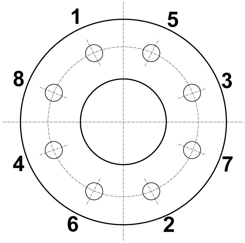
Example only, number of bolts will vary, apply the same criss cross process, gradually tightening more after each revolution.
SIGHT GLASSES - SLSG SERIES Australian Pipeline Valve - Installation, Operation and Maintenance Manual 10
torque sequence: 1 – 2 – 3 – 4 – 5 – 6 – 7 - 8
DIAGRAM 1 Bolting
BOLTING TORQUES NPS DN Bolt N-m in/lb 1/2” 15 35 310 3/4” 20 35 310 1” 25 35 310 1 1/4” 32 45 398 1 1/2” 40 45 398 2” 50 50 443 2 1/2” 65 50 443 3” 80 50 443 4” 100 55 487 5” 125 65 575 6” 150 65 575 8” 200 80 708
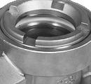
SLSG SERIES - SCREWED ENDS
Top View
00
SIGHT GLASSES - SLSG SERIES Australian Pipeline Valve - Installation, Operation and Maintenance Manual 11 www.australianpipelinevalve.com.au 1 3 4 2 6 5 H d K L 15NB ~ 25NB
K1 L øK K1 H 1 1/4” ~ 2” 2 6 5 4 7 3 1 ød
~ 50NB
32NB
Dimensions in millimeters
N
N
CHECKED
43
NO. PART NAME MATERIAL NOTES 1 2 3 4 5 6 BODY CAP GASKETS (4) STEM GLASS INDICATOR ASTM
CF8M
GLASS
CF8M DIMENSIONS (MM) & WEIGHT (KG) DN d L H K 15 20 25 40 50 15 112 68 38 20 112 68 38 25 112 68 38 40 145 110 45 50 168 131 55 APV DWG FRM 43 - - - - -Australian
B.T. S.Q. C.C. Inch 1/2” 3/4” 1” 1 1/2” 2” Weight 2.5 2.6 3.6 7 10 RATING DESIGN & MFG. PRESS-TEMP RATING FACE TO FACE DIM. TEST & INSPECTION PORT SIZE TRIM END CONNECTION END DIMENSION MARKING & PAINT OTHER REQ. NOTES OTHER 1378
CWP
SEE
NPT
INVESTMENT
TEST
SHELL
SEAT
BACKSEAT TEMPERATURE MEDIUM Water, Oil, Gas ºC MAX 200 ºF MAX 392 Mpa Psi Mpa Psi Mpa Psi Mpa Psi 2.07 300 32 32 145 110 45 1 1/4” 5 7 BOLT A2-70
SS) 32 ~ 50 NB K1 10 10 10 10 10 10
15NB ~ 25NB 32NB ~ 50NB BILL OF MATERIALS
Screwed End Sight Glass, Model SLSGSS-S, NPS 1/2” ~ 1” (DN15~DN25) 1378 kPa (200 PSI) WOG ORDER
o / DWG
o REV. APPROVED
DRAWN
A351 CF8M ASTM A351
PTFE SUS316 BOROSILICATE
ASTM A351
Pipeline Valve
kPa / 200 PSI
ASME B16.34
TABLE MFG STANDARD API 598/ISO 5208 FULL 316 BSPT OR NPT BS21/ ISO7-1-RC (AS1722.1) BSPT OR ASME B1.20.1
MSS SP-25 PICKLED & PASSIVATED
CAST BODY DOUBLE SIDED
PRESSURE
HYDRO SEAT HYDRO
AIR
(304
SLSG SERIES (15NB ~ 100NB)
BILL OF MATERIALS
NO. PART NAME MATERIAL NOTES 1 2 3
PTFE SUS316 BOROSILICATE GLASS ASTM A351 CF8M
8.8 ZINC PLATED
BOLT
7
TEST PRESSURE SHELL HYDRO GLASS HYDRO
2.16 313
Psi
Psi
Mpa
Psi Mpa
SEAT AIR Mpa
ºC MAX 200 ºF MAX 392 Mpa
CL 150 BODY/FLANGES ASME B16.34 (WALL) ASME B16.34
DIN 3202-F1 ASME B16.5 RF 3.2 ~ 6.3Ra (125 ~ 250AARH) API 598/ISO 5208
MSS-SP25, PAINT PPWF07.002 1960 KPA CWP (285 PSI) BODY & GLASS P/T ASME B16.34
FULL 316 INVESTMENT CAST BODY DOUBLE SIDED FLOW INDICATOR
RATING DESIGN & MFG.
PRESS-TEMP
APPROVED CHECKED DRAWN 660
ORDER N o / DWG N o REV.
660
APV DWG FRM
SIGHT GLASSES - SLSG SERIES Australian Pipeline Valve - Installation, Operation and Maintenance Manual 12 www.australianpipelinevalve.com.au 6 3 4 5 2 1 7 øD øC øG ød H f T N-øM L d1 K
Dimensions in millimeters
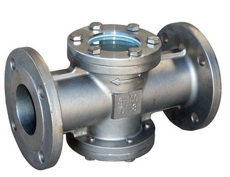
Sight Glass, Model SLSG150CS-L2, NPS 1/2”~4” (DN15~DN100) Class 150, Flanged End 4 5
00
6 BODY CAP GASKETS (4) HINGE PIN GLASS WINDOW INDICATOR
ASTM A216 WCB ASTM A216 WCB
-
- - - -
B.T. S.Q. C.C.
DIMENSIONS (MM) & WEIGHT (KG)
-
Australian Pipeline Valve
RATING FACE TO FACE DIM. END DIMENSION END CONNECTION TEST & INSPECTION MARKING & PAINT OTHER REQ. PORT SIZE TRIM NOTES OTHER
BACKSEAT TEMPERATURE MEDIUM Water, Oil, Gas Psi
SUS304
Inch DN d d1 L H D C G f T N-M Weight 1/2” 3/4” 1” 1 1/4” 1 1/2” 2” 2 1/2” 3” 4” 15 20 25 32 40 50 65 80 100 15 20 25 32 40 50 65 80 100 35 35 35 55 55 55 85 85 110 130 150 160 180 200 230 290 310 350 115 115 115 143 143 143 185 196 228 89 98 108 117 127 152 178 190 229 60.5 70.0 79.5 89.5 98.5 120.5 139.5 152.5 190.5 35 43 51 64 73 92 105 127 157 1.6 1.6 1.6 1.6 1.6 1.6 1.6 1.6 1.6 11.1 11.1 11.1 12.7 14.3 15.9 17.5 19.1 23.9 4-16 4-16 4-16 4-16 4-16 4-19 4-19 4-19 8-19 3.0 4.0 5.6 6.8 9.0 11.0 14.0 19.0 25.0 K 10 10 10 10 10 10 12 12 15 *BOROSILICATE GLASS RATED TO 1960 KPA CWP
SLSG SERIES (125NB ~ 150NB)
BILL OF MATERIALS
TEST PRESSURE SHELL HYDRO GLASS HYDRO SEAT AIR
Mpa Psi Mpa Psi Mpa Psi Mpa Psi 2.16 313 * *
ºF MAX 392
BACKSEAT TEMPERATURE MEDIUM Water, Oil, Gas ºC MAX 200
- - - - (1) Australian Pipeline
CL 150 BODY/FLANGES ASME B16.34 (WALL) ASME B16.34 DIN 3202-F1 ASME B16.5 RF 3.2 ~ 6.3Ra (125 ~ 250AARH) API 598/ISO 5208
MSS-SP25, PAINT PPWF07.002 * 1600 KPA MAXIMUM CWP BOROSILICATE GLASS FULL 316 INVESTMENT CAST BODY DOUBLE SIDED FLOW INDICATOR
BOROSILICATE GLASS, BODY IS FULL ANSI 150 RATED B16.34
APV DWG FRM 661 -
PRESSURE
N o / DWG N o REV.
ORDER
RATING
KPA MAXIMUM COLD WORKING
(1) 200 º C MAXIMUM *1600
PRESS-TEMP
FACE
N-M
T
f
G
C
D
H
L
8-22 8-22
23.9 25.4
1.6 1.6
186 216
216.0 241.5
254 279
268 310
400 480
15
18
30.0 48.0 K
135 160
125 150
125 150
Weight 5” 6”
SIGHT GLASSES - SLSG SERIES Australian Pipeline Valve - Installation, Operation and Maintenance Manual 13 www.australianpipelinevalve.com.au 6 3 4 5 2 1 7 øD øC øG ød H f T N-øM L d1 K
Dimensions in millimeters
APPROVED
NO.
Sight Glass, Model SLSG150CS-L2, NPS 5”~6” (DN125~DN150) Class 150, Flanged End NOTES 1 2 3 4 5 6
CHECKED DRAWN 661 00
PART NAME MATERIAL
BODY CAP GASKETS (4) HINGE PIN GLASS WINDOW INDICATOR
ASTM A216 WCB ASTM A216 WCB PTFE SUS316 BOROSILICATE GLASS ASTM A351 CF8M
B.T. S.Q. C.C.
DIMENSIONS (MM) & WEIGHT (KG)
Valve
DESIGN & MFG.
RATING
TO FACE DIM. END DIMENSION END CONNECTION TEST & INSPECTION MARKING & PAINT OTHER REQ. PORT SIZE TRIM NOTES OTHER
7 Inch
BOLT DN
SUS304 d
8.8 ZINC PLATED d1
BILL OF MATERIALS
TEST PRESSURE SHELL HYDRO GLASS HYDRO SEAT AIR
CL 150* BODY/FLANGES ASME B16.34 (WALL) ASME B16.34 DIN 3202-F1 ASME B16.5 RF 3.2 ~ 6.3Ra (125 ~ 250AARH) API 598/ISO 5208
MSS-SP25, PAINT PPWF07.002 * 1378 KPA MAX CWP BOROSILICATE GLASS FULL 316 INVESTMENT CAST BODY DOUBLE SIDED FLOW INDICATOR
BOROSILICATE GLASS, BODY IS FULL ANSI 150 RATED B16.34
WORKING PRESSURE
MAXIMUM COLD
TEST
*1378 KPA
DWG FRM 662 - - - - -Australian Pipeline
APPROVED CHECKED DRAWN 662 00
S.Q. C.C. RATING DESIGN & MFG. PRESS-TEMP RATING
APV
ORDER N o / DWG N o REV.
N-M
T
f
G
8.8 ZINC PLATED H
SUS304 L
C
D
BOLT d1
8-22
28.6
1.6
270
298.5
343
400
600
19
75.0 K
200
200
200
Weight 8”
SIGHT GLASSES - SLSG SERIES Australian Pipeline Valve - Installation, Operation and Maintenance Manual 14 www.australianpipelinevalve.com.au 6 3 4 5 2 1 7 øD øC øG ød H f T N-øM L d1 K
Dimensions in millimeters
NO. PART
MATERIAL
Sight Glass, Model SLSG150CS-L2, NPS 8” (DN200) Class 150, Flanged End 1 2 3 4 5 6
NAME
NOTES
BODY CAP GASKETS HINGE PIN GLASS WINDOW INDICATOR
ASTM A216 WCB ASTM A216 WCB
B.T.
FACE
PTFE SUS316 BOROSILICATE GLASS ASTM A351 CF8M
Valve
TO FACE DIM. END DIMENSION END CONNECTION
& INSPECTION MARKING & PAINT OTHER REQ. PORT SIZE TRIM NOTES OTHER
BACKSEAT TEMPERATURE MEDIUM Water, Oil, Gas ºC MAX 200 DIMENSIONS (MM) & WEIGHT (KG) Inch
ºF MAX 392 DN
Mpa Psi Mpa Psi Mpa Psi Mpa Psi 2.16 313 * * 7 d
SLSG SERIES (200NB)
NOTES Australian Pipeline Valve - Installation, Operation and Maintenance Manual
NOTES Australian Pipeline Valve - Installation, Operation and Maintenance Manual

© Copyright Australian Pipeline Valve 1990 - 2024 Edition
Catalogues, photos, brochures and technical publications are the exclusive property of Australian Pipeline Valve. Any unauthorised reproduction in total or in part, shall result in prosecution. Products and data sheets in this publication are subject to change at anytime without notice. Australian Pipeline Valve reserves the right to carry out amendments to products and materials.
NOTES Australian Pipeline Valve - Installation, Operation and Maintenance Manual

www.australianpipelinevalve.com.au AUSTRALIAN PIPELINE VALVE® HEAD OFFICE 70-78 Stanbel Road Salisbury Plain South Australia 5109 Telephone +61 (0)8 8285 0033 email: admin@australianpipelinevalve.com.au If you have any requirements in the field of valves, please contact us for a prompt response. Continuous development of Australian Pipeline Valve products may necessitate changes in the design or manufacture process. Australian Pipeline Valve reserves the right to effect any such changes without prior notice. © Australian Pipeline Valve 1990 - 2024 Edition LOCAL DISTRIBUTOR/AGENT IOM Flowturn Sight Glass
