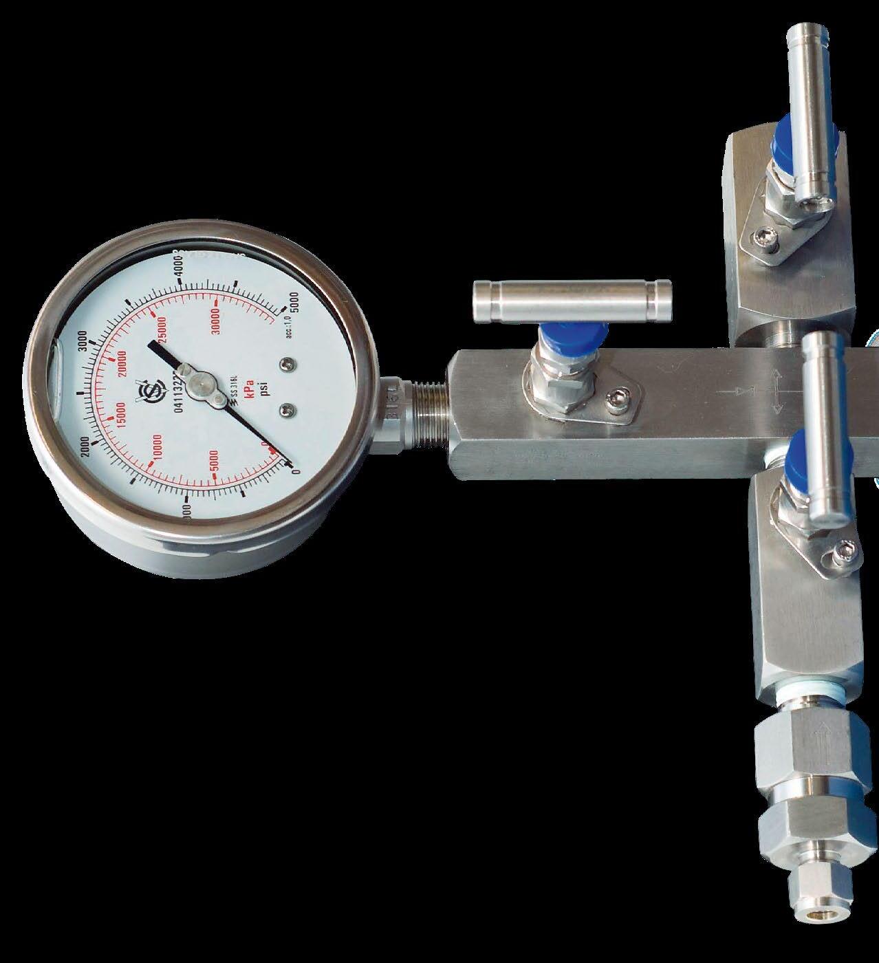
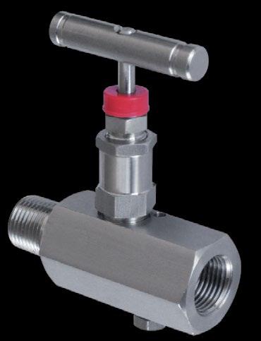
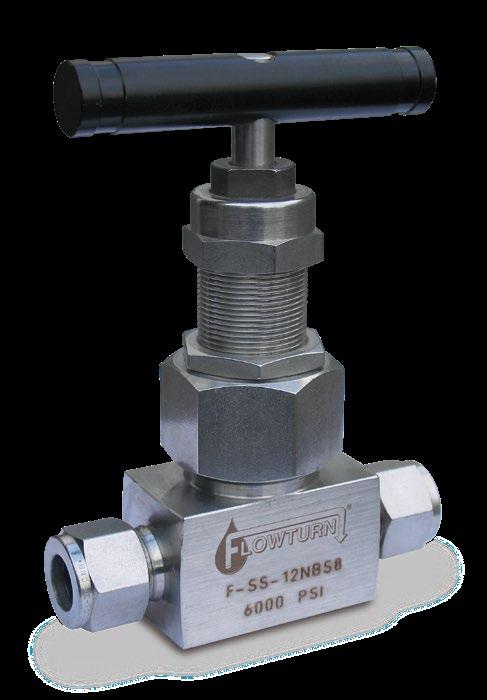
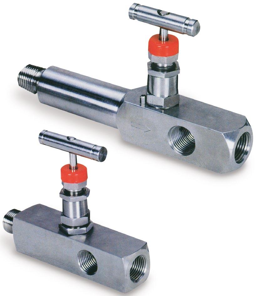
METAL SEATED GLOBE TYPE NEEDLE VALVES
www.australianpipelinevalve.com.au INSTALLATION, OPERATION & MAINTENANCE MANUAL
S-H5, S-H7, S-H71, S-M5, S-M9
COMPLETE PRODUCT LINE
“Australian Pipeline Valve produces isolation, control and flow reversal protection products for severe and critical service media in utility, steam, pipelines, oil & gas and process industries. APV valves and pipeline products form the most competitive portfolio in the market.”


View our catalogues at www.australianpipelinevalve.com.au AUSTRALIAN PIPELINE VALVE BRAND RANGE - CATALOGUES APV FAMILY OF BRANDS RANGE - CATALOGUES
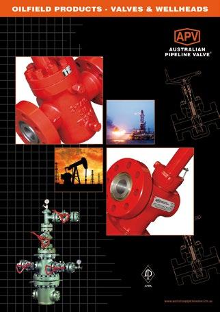
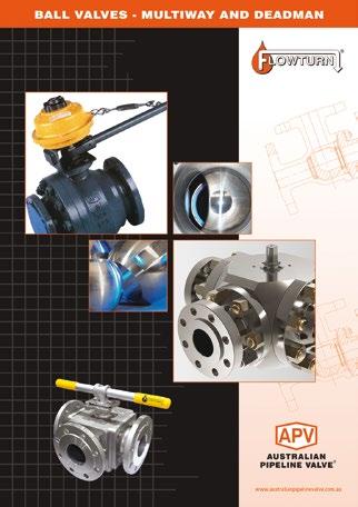
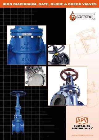
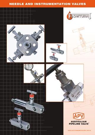
Oilfield Products Valves & Wellheads Gate, Globe & Check Valves - Forged Steel Plug Valves Lubricated, Sleeved & Lined Gate, Globe & Check Valves - Cast Steel Diamond Gear Gearboxes Flowturn Gate, Globe & Check Valves Flowturn Instrument Valves Flowturn Ball Valves Multiway & Deadman Flowturn Strainers & Sight Glasses Supercheck Wafer Check Valves Superseal Butterfly Valves Steamco Steam Valves Superseal Industrial Ball Valves TwinLok Tube Fittings Uniflo Check Valves
Actuators
Valves Floating & Trunnion Mounted Ball Valves Floating Small Bore Ball Valves Special Service Product Brochure Contact us for your local stockist/distributor
Torqturn
Ball


Overview 2-3 Safety Information 3-4 Introduction 4 1.0 Installation 4-5 2.0 Operation 5 3.0 Maintenance 5-7 3.1 Stem seal replacement 6 3.2 Reassembly of the stem onto the valve 7 3.3 Seat replacement 7 4.0 Final Inspection 7 Appendix 8 METAL SEATED NEEDLE VALVE - S-H5, S-H7, S-H71, S-M5, S-M9 INDEX Australian Pipeline Valve - Installation, Operation and Maintenance Manual 1 © Copyright Australian Pipeline Valve 1990 - 2024 Edition Catalogues, photos, brochures and technical publications are the exclusive property of Australian Pipeline Valve. Any unauthorised reproduction in total or in part, shall result in prosecution. Products and data sheets in this publication are subject to change at anytime without notice. Australian Pipeline Valve reserves the right to carry out amendments to products and materials.
OVERVIEW
The majority of this information is common knowledge to experienced steel valve users. When properly installed in applications for which they were designed, Flowturn valves will give long reliable service under normal conditions. This instruction is only a guide for installation and operation on standard service and covers general maintenance and minor repairs. A professional APV approved valve engineering facility should be utilised for reconditioning or major repairs.
Note
We do recommend however that this entire document be read prior to proceeding with any installation or repair. Australian Pipeline Valve and it’s parent company take no responsibility for damage or injury to people, property or equipment. It is the sole responsibility of the user to ensure only specially trained valve repair experts perform repairs under the supervision of a qualified supervisor.
RESPONSIBILITY FOR VALVE APPLICATION
The End User is responsible for ordering the correct valves. Flowturn valves are to be installed in the observance of the pressure rating and design temperature. Prior to installation, the valves and nameplates should be checked for proper identification to be sure the valve is of the proper type, material and is of a suitable pressure class and temperature limit to satisfy the application’s requirements.
The End User is responsible for ordering the correct valves. Flowturn valves are to be installed in the observance of the pressure rating and design temperature. Prior to installation, the valves and nameplates should be checked for proper identification to be sure the valve is of the proper type, material and is of a suitable pressure class and temperature limit to satisfy the application’s requirements.
RECEIVING INSPECTION AND HANDLING
Valves should be inspected upon receipt to determine:
- Compliance to purchase order requirements.
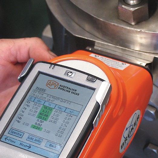
- Correct type, pressure class, size, body and trim materials and end connections (this information may be found on the nameplate or may be stamped on the body of the valve).
- Any damage caused during shipping and handling to end connections, handwheel or stem.
METAL SEATED NEEDLE VALVE - S-H5, S-H7, S-H71, S-M5, S-M9 Australian Pipeline Valve - Installation, Operation and Maintenance Manual 2
The End User is advised that misapplication of the product may result in injuries or property damage. A selection consistent with the particular performance requirements is important for proper application and is the sole responsibility of the user.
SAFETY INFORMATION
The following general safety notices supplement the specific warnings and caution as appearing in this manual. They are recommended precautions that must be understood and applied during operation and maintenance of the equipment covered in this I.O.M.
Never attempt to disassemble a valve while there is pressure in the line. Make sure both upstream and downstream pressures are removed. Disassemble with caution in the event all pressures are not relieved. Even when replacing gaskets or packing seals, caution is necessary to avoid possible injury.
To prevent valve distortion, inefficient operation, or early maintenance problems, support piping on each side of the valve.
• A valve is a pressurised device containing fluids under pressure and should be handled with appropriate care.
• Valve surface temperature may be dangerously too hot or too cold for skin contact.
• Upon disassembly, attention should be paid to the possibility of releasing dangerous and or ignitable accumulated fluids.
• Adequate ventilation should be available for service.
This manual provides instructions for storing, general servicing, installation and removal of needle valves.
APV - Flowturn and it’s resellers refuse any liability for damage to people, property or plant as well as loss of production and loss of income under any circumstances but especially if caused by: Incorrect installation or utilisation of the valve or if the valve installed is not fit for intended purpose. It is the sole responsibility of the client to ensure the valve type and materials are correctly specified.
Australian Pipeline Valve - Installation, Operation and Maintenance Manual 3 METAL SEATED NEEDLE VALVE - S-H5, S-H7, S-H71, S-M5, S-M9
DURING OPERATION BEAR IN MIND THE FOLLOWING WARNINGS:
a- The graphoil packing/seals where used are very brittle, any twisting or bending shall be avoided.
b- The internal parts of valves (plug, tip, stem, seat) shall be handled with care avoiding scratches or surface damage.
c- All tools and equipment for handling and supporting the internal parts shall be coated with soft materials.
d- Seals can include Viton, NBR, Buna & Teflon hence high temperatures, and some chemicals will damage sealing components.
For all operations make references to position number on part list of the applicable drawing listed.
INTRODUCTION
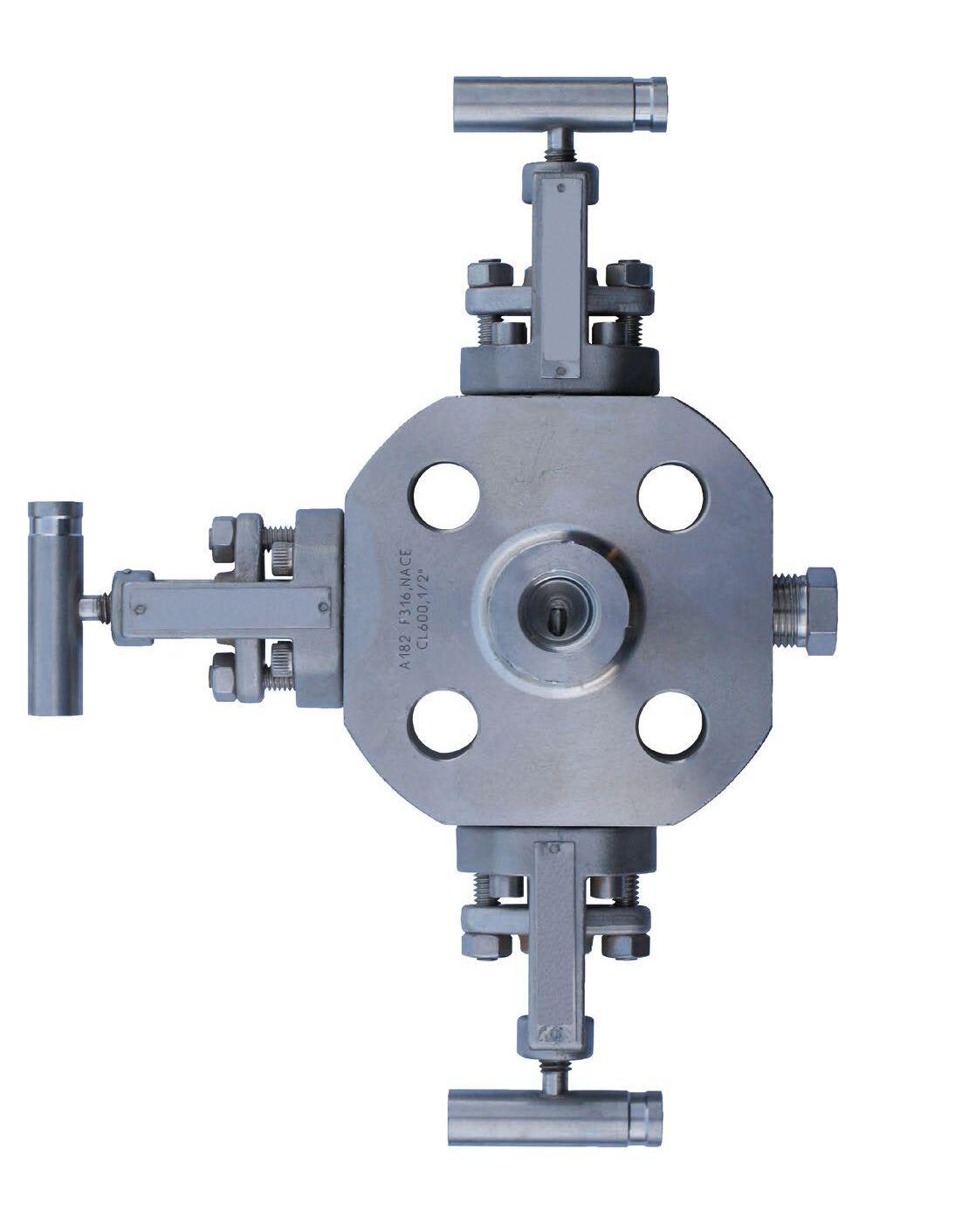
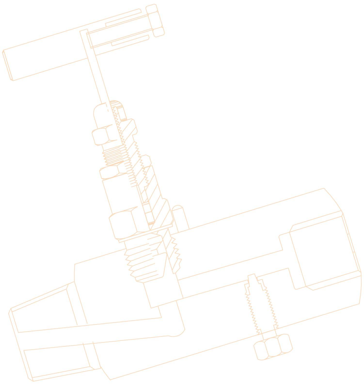
Flowturn S-H5, S-H7, S-H71, S-M5, S-M9 and S-H7PM Needle valves are metal-seated with a globe configuration. Soft seated design is also available on request. The plug/ball tip is free-swivelling stainless steel with Teflon or Graphite packing. These valves are provided with a variety of end connections. For maximum pressure-temperature ratings refer to catalogue or consult us. Where Teflon packing is used the maximum temperature rating is 200°C. Only an APV approved valve repairer should undertake complete reconditioning or major repairs.
1.0 INSTALLATION
Piping should be properly aligned and supported to reduce mechanical loading on the end connections.
1. Check valve body for flow arrow to ensure correct flow orientation. These valves can be installed in vertical or horizontal piping.
2. Prior to valve installation, check the piping to which the valve is to be connected for cleanliness and remove any foreign materials.
3. Threaded joints require an intimate fit between the male and female pipe threads. The use of a thread sealant is recommended. Ensure the fitting connections are made up tight.
4. Keep the valve partially open during welding. All welding should be in accordance with any code or applicable regulations relevant to the piping system construction and with complete and approved welding procedures. Graphite packed valves are recommended for welding applications. Excessive heat can distort metal components in the valve, including the seat area. Heat input should be kept to a minimum by controlling the amperage and voltage to the lowest practical levels. A minimum travel
Australian Pipeline Valve - Installation, Operation and Maintenance Manual 4 METAL SEATED NEEDLE VALVE - S-H5, S-H7, S-H71, S-M5, S-M9
speed of three (3) I.P.M. should be maintained and the interpass temperature should not exceed 93°C (200°F). GTAW weld type should be employed with argon gas and a maximum diameter weld rod of 1/8”. Only a certified welder with experience in welding this type of valve should be used.
2.0 OPERATION
The user should ensure suitably qualified specialist engineers have matched the valve type to the valve service application and ensure valves are properly installed. Valves have moving and wearing parts and depend on long-term preservation of highly finished surfaces on these parts for satisfactory valve performance.
1. The use of excessive force, additional leverage or over cheating to operate the valve handle is not recommended. This practise can cause valve damage.
2. All needle valves have rising stems with right hand thread. Rotate the handle counter-clockwise to open and clockwise to close. Ball or ‘V’ seated valves should be closed at 0.55-0.69 kg-m (4-5 ft lb) or torque.
3.0 MAINTENANCE
Valves which remain in one position for long periods of time are even more likely to require maintenance attention due to the loss of effective lubricants in threads, aging of packing, surface corrosion or moving parts or accumulation of harmful solids. Depending on the surface conditions, environment type, temperature, frequency of use, pressure, etc. In some applications it may become necessary to schedule periodic partial or full cycle exercising and maintenance of these valves.
1. Stem packing/seal leakage usually results from seal wear, and can usually be corrected by tightening the bonnet bushing. Over tightening can cause high stem friction, accelerated wear and shortened stem seal life.
2. If stem packing replacement is needed, safe practice requires depressurising the valve before removal of the bonnet bushing. Use of backseat (where present) to permit repacking under pressure should be considered unsafe.
Always wear appropriate safety wear and ensure all fluids and media are drained prior to commencing maintenance.
Australian Pipeline Valve - Installation, Operation and Maintenance Manual 5 METAL SEATED NEEDLE VALVE - S-H5, S-H7, S-H71, S-M5, S-M9
3.1 STEM SEAL REPLACEMENT
Teflon and Graphite seals/packings do not often need replacement if leakage occurs usually the leak can be stopped by tightening the bonnet bushing.
1. Refer to Table A in the Appendix for identification of parts. The design may vary depending on size, rating, special bonnet options and trim. Refer to the as-built drawing.
2. Remove bonnet lock pin (item #10) from valve body, using pliers or wire cutters.
3. Unscrew bonnet counter-clockwise to remove bonnet assembly from the valve.
4. Place bonnet in soft-jawed vice to facilitate disassembly.
5. Remove T-bar handle (part #2) by loosening grub screw (part #1).
6. Remove plastic dust cover (part #4) from gland retainer bush (part #5).
7. Loosen lock nut (part #6) and unscrew bush off stem.
8. Remove valve stem (part #3) from bonnet (part #7) by screwing downward.
9. Remove Teflon or Graphite stem packing (part #9) and the two washers (part #9a).
10. Clean all parts with suitable cleaner such as acetone.
11. Inspect all parts for damage; especially the threads and stem tip area. Replace both the stem and bonnet bush if threads do not engage smoothly.
12. Lubricate the stem (part #3) threads and bush (part #5) with lubricant resistant to the service in which the valve is being used.
13. Re-insert the stem and tip (part #3) into the end of the bonnet that is threaded externally.
14. Push the stem upward from the bottom of the bonnet.
15. Place the stem packing (part #9) and packing washers (part #9a) over the stem and push it down into the bonnet.
16. Place the retainer bush (part #5) with lock nut (part #6) over the stem and hand screw the threads. Screw the bushing down into the bonnet until it reaches the stem seal.
17. Place the dust cover (part #4) over the valve stem (part #3).
18. Place the handle (part #2) and tighten the grub screw where applicable (part #1) to 1.38-1.66 kg-m (10-12ft lbs). Take care not to bend the stem.
Do not attempt to repack the valve in-line, especially if under line pressure.
Australian Pipeline Valve - Installation, Operation and Maintenance Manual 6 METAL SEATED NEEDLE VALVE - S-H5, S-H7, S-H71, S-M5, S-M9
3.2 REASSEMBLY OF THE STEM ONTO THE VALVE
1. Lubricate the bonnet threads with appropriate lubricant.
2. Insert the bonnet into the seat cavity hand screw the bonnet into the valve body.
3. Then tighten the bonnet to the torque value shown below: -
S-H5, S-H7, S-M5, S-M9: -
Carbon Steel 4.42-5.24 kg-m (32-38 ft lb)
Stainless Steel 4.83-5.52 kg-m (35-40 ft lb)
S-H71 (10,000 psi): -
Carbon & Stainless Steel 5.52-6.21 kg-m (40-45 ft lb)
4. Tighten bonnet bush with a wrench, take care not to over tighten. Then check the tightness by turning the handle. If it feels too loose, tighten the bush more. It is feels tight, the stem packing should be replaced and the bush again re-tightened.
5. The bush tightness requires judgement and experience. It if is too loose the bonnet will leak. If it is too tight, the handle will be hard to turn and the stem seal may be damaged.
6. Then tighten the lock nut (part #6) to lock the bush in place.
7. Replace bonnet lock pin.
3.3 SEAT REPLACEMENT
If the valve seat area in the valve itself is worn enough to cause leakage the seat maybe resurfaced with a seat re-surfacing tool. However, first ensure it is not the stem ball or v-tip that is damaged. Follow the procedure of paragraphs 3.1 and 3.2 for removal and installation of the bonnet.
MATERIAL OF CONSTRUCTION (EXAMPLE)
4.0 FINAL INSPECTION
Turn the handle to close and open the valve. Check for sticking, rubbing or any resistance to smooth operation.
Australian Pipeline Valve - Installation, Operation and Maintenance Manual 7 METAL SEATED NEEDLE VALVE - S-H5, S-H7, S-H71, S-M5, S-M9
Sr No. Part Qty. Material 1 Body 1 A479-316/ A-105* 2 Stem 1 A479-316 3 Spacer 2 A479-316 4 Gland Body 1 A479-316/ A-105* 5 Gland Packing 2 Teflon/ Graphoil 6 Gland Lock Nut 1 A479-316/ A-105* 7 Gland Retainer 1 A479-316/ A-105* 8 Dust Cap 1 Plastic/ LD 9 Grub Screw 1 A479-316 10 Washer 1 A479-316 11 Handle 1 Stainless Steel 12 Vee/ Ball Tip 1 Titanium/ 17-4PH/ 316/ HF * CAD or Zinc plated
NonRotatingVeeTipNonRotatingBallTip 12 10 5 3 2 9 11 8 7 6 4 1
METAL
APPENDIX
TABLE A
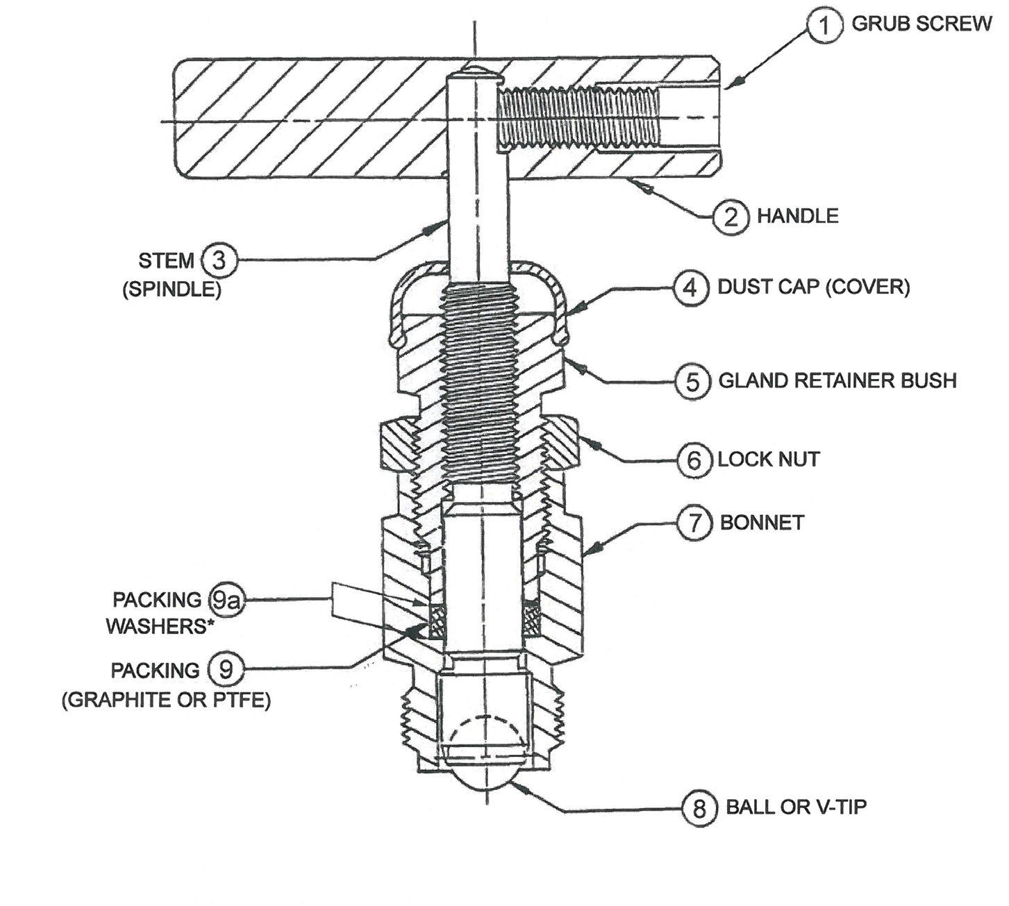
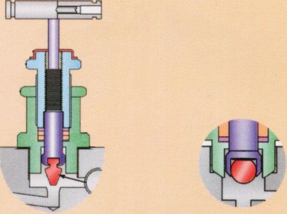
TEFLON OR GRAPHITE PACKED - HARD SEAT
BALL OR V-TIP STEM
* Packing washers may only be required on graphite packed valves.
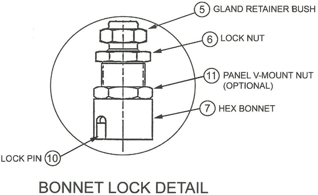
BONNET
LOCK DETAIL
(The above drawings are indicative only, design will vary according to different sizes, special bonnet options and different trim material options. Refer to actual drawing when ordering spares.)
Australian Pipeline Valve - Installation, Operation and Maintenance Manual 8
SEATED NEEDLE VALVE - S-H5, S-H7, S-H71, S-M5, S-M9
Australian Pipeline Valve - Installation, Operation and Maintenance Manual 9 NOTES

www.australianpipelinevalve.com.au AUSTRALIAN PIPELINE VALVE® HEAD OFFICE 70-78 Stanbel Road Salisbury Plain South Australia 5109 Telephone +61 (0)8 8285 003 email: admin@australianpipelinevalve.com.au If you have any requirements in the field of valves, please contact us for a prompt response. Continuous development of Australian Pipeline Valve products may necessitate changes in the design or manufacture process. Australian Pipeline Valve reserves the right to effect any such changes without prior notice. © Australian Pipeline Valve 1990 - 2024 Edition LOCAL DISTRIBUTOR/AGENT IOM Flowturn Needle Metal
