INTRODUCTION
The majority of this information is common knowledge to experienced valve and gearbox users. When properly installed in applications for which they were designed, Australian Pipeline Valve (APV)Diamond Gear gearboxes will give long reliable service. This instruction is only a guide for installation and operation on standard service and covers general maintenance and minor repairs. A professional APV approved engineering facility should be utilised for reconditioning or major repairs.
Note
We do recommend however that this entire document be read prior to proceeding with any installation or repair. Australian Pipeline Valve and it’s parent company take no responsibility for damage or injury to people, property or equipment. It is the sole responsibility of the user to ensure only specially trained valve repair experts perform repairs under the supervision of a qualified supervisor.
RESPONSIBILITY FOR VALVE/GEARBOX APPLICATION
The User is responsible for ordering the correct gearboxes. The user is responsible for ensuring APVDiamond Gear gearboxes are selected and installed in conformance with the torque service and design temperature requirements. Prior to installation, the gearbox drawing and nameplates should be checked for proper identification to ensure the gearbox is of the proper type, material and is of a suitable size and temperature rating to satisfy the requirements of the service application.
Do not use gearboxes in applications where the temperature is higher than the allowable working values. Gearboxes should not be used in environments if not compatible with the gearbox materials of construction, as this will cause chemical attacks, leakage, valve failure.
RECEIVING INSPECTION AND HANDLING
Gearboxes should be inspected upon receipt to ensure:
- Conformance with all purchase order requirements.
- Correct type, model, size, body and trim materials.
- Any damage caused during shipping and handling to end connections, hand wheel or stem.
The User is advised that specifying an incorrect gearbox for the application may result in injuries or property damage. Selecting the correct gearbox type, material and mounting, in conformance with the required performance requirements is important for proper application and is the sole responsibility of the user.
MULTI-TURN BEVEL GEARBOX - BA SERIES Australian Pipeline Valve - Installation, Operation and Maintenance Manual 2
SAFETY INFORMATION
The following general safety information should be taken in account in addition to the specific warnings and cautions specified in this manual. They are recommended precautions that must be understood and applied during operation and maintenance of the equipment covered in this I.O.M.
• Gearbox surface temperature may be dangerously too hot or too cold for skin contact.
• Ensure adequate ventilation is available for service.
This manual provides instructions for storing, general servicing, installation and removal of gearboxes.
APV and it’s resellers refuse any liability for damage to people, property or plant as well as loss of production and loss of income under any circumstances but especially if caused by: Incorrect installation or utilisation of the gearbox or if the gearbox installed is not fit for intended purpose. It is the sole responsibility of the user to ensure the gearbox type and materials are correctly specified.
DURING OPERATION TAKE INTO ACCOUNT THE FOLLOWING WARNINGS:
a- The gearboxes internal parts shall be handled with care avoiding scratches or surface damage.
b- All tools and equipment for handling the internal parts shall be soft coated.
c- Gearboxes can be fitted with seals in Buna, Viton, etc., hence high temperatures will damage sealing components.
For all operations make reference to position number on part list of the applicable drawing listed.
Personal injury may result from sudden release of any process pressure. APV recommends the use of protective clothing, gloves and eye wear when performing any installation or maintenance.
Isolate the valve from the system and relieve pressure prior to performing maintenance.
If a gasket seal is disturbed while removing or adjusting gasketed parts, APV recommends installing a new gasket while reassembling. A proper seal is required to ensure optimum operation.
MULTI-TURN BEVEL GEARBOX - BA SERIES Australian Pipeline Valve - Installation, Operation and Maintenance Manual 3
Potential HIGH PRESSURE vessel - be aware of high-pressure hazards associated with the attached valve or other actuated device when installing or performing maintenance on the operator. Do not remove the operator bolts from the valve or actuated device unless the valve or device stem is secured or there is no pressure in the line.
For maintenance and/or disassembly of the operator when installed on the valve, ensure that the operator is not under thrust or torque load. If the valve must be left in service, the valve stem must be locked in such a way as to prevent any movement of the valve stem.
Do not manually operate the operator with devices other than the installed handwheel. Using force beyond the ratings of the operator and/or using additive force devices such as cheater bars, wheel wrenches, pipe wrenches, or other devices on the operator handwheel may cause serious personal injury and/or damage to the operator and valve.
Do not exceed any design limitations or make modifications to this equipment without first consulting us.
Use of the product must be suspended any time it fails to operate properly. Standard gearboxes are not suitable for motor actuation. A special heavy duty version can be specified for this purpose.
Do not use replacement parts that are not genuine Diamond Gear parts, as serious personal injury and/or damage to the operator and valve may result.
1.0 DESCRIPTION
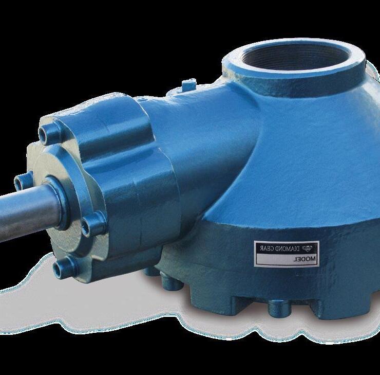
The Diamond Gear BA series gear operators offer simple and reliable manual positioning of valves and other multi-turn devices. All Diamond Gear BA units combine rugged construction, light weight and modular design to provide the cost efficient and most cost effective solution for actuation of process valves such as rising and non rising stem gate, globe and sluice valves. These operators have a bevel gear transmission with completely enclosed construction. The main casing is designed to withstand the shock and vibration normally encountered in piping systems. The housing, gears and shaft are precision machined from quality and tested raw materials and assembled with utmost care for smooth and reliable operation. The gearboxes can be supplied with various types of bases.
Gear operators should be sized with at least a 40% safety factor or even more if high or low temperature or dirty service or infrequent use. Valves should be regularly opened to avoid sticking. Most valves will increase in torque over time as debris, corrosion, increased pressure, erosion, infrequent use, sticking of seats, etc., all effect torque. Also the theorectical torque of a valve can be dramatically different to the actual torque.
MULTI-TURN BEVEL GEARBOX - BA SERIES Australian Pipeline Valve - Installation, Operation and Maintenance Manual 4
2.0 STORAGE
BA Gear Operators don’t have a shelf life however, store in a clean, dry area protecting the input and output bores from corrosion and damage by sealing each unit in a plastic bag.
Store on wooden skids to protect the machined mounting flange. If the operators must be stored outside, they must be covered in polyethylene with silica gel crystals to absorb moisture. Input shafts should be rotated every three months to mix lubricant.
3.0 OPERATION
Operation of the wheel will actuate the process valve.
3.1 SAFETY PRACTICE
Do not use oversize handwheels or cheater/leverage bars. This can result in damage to the gearbox. Do not fit electric motors to standard BA gearboxes, actuated gearboxes must be specified at time of order.
The following check points should be performed to maintain safe operation of the BA gear operator:
• Set up a periodic operating schedule on frequently used valves.
• Ensure that the limit and/or torque switches on any electric actuator fitted to the bevel gear operator are correctly and appropriately adjusted.
4.0 INSTALLATION
BA series gear operators have been designed to transmit torque as well as thrust. The gear operator can be supplied with a threaded stem nut, keyed stem nut, or a blank stem nut, or a claw connector (the claw connector can drive the existing stem nut on the valve).
4.1 INSTALLING OPERATOR WITH A THREADED STEM NUT
a. Position operator above the valve stem.
b. Rotate the handwheel or wrench nut several turns until there is positive engagement between the valve stem and the operator stem nut.
c. Rotate the handwheel to lower the operator on the valve until contact has been made with the valve flange.
d. Bolt the gear operator to the valve mounting flange.
MULTI-TURN BEVEL GEARBOX - BA SERIES Australian Pipeline Valve - Installation, Operation and Maintenance Manual 5
4.2 INSTALLING AN OPERATOR WITH A BLANK STEM NUT
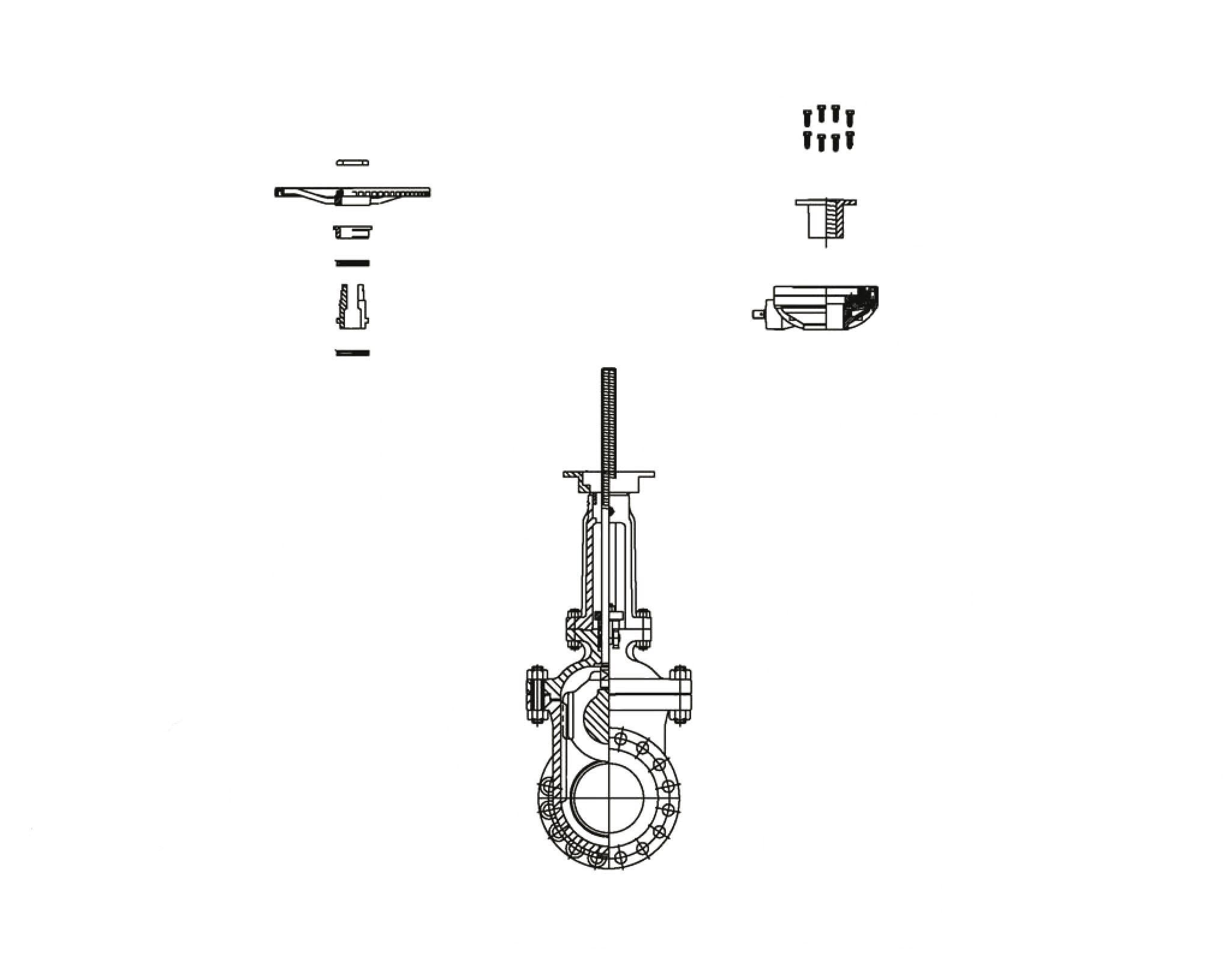
a. Remove the thrust ring from the base of the operator. Ensure the O-ring seals (where applicable) located on the ring are not damaged.
b. Remove the stem nut assembly consisting of a bronze or D2C nut and two roller bearings (where applicable) with washers.
c. Remove bearings (where applicable) and washers.
d. Machine the blank stem nut to suit the valve stem. Take care during machining not to damage surfaces on the stem nut. Ensure that no dirt or particulates enters the operator. Alternatively machine the blank stem nut and the existing valve yoke nut to mate with each other.
e. Reassemble the operator, reversing steps a, b, and c.
1. Install bearings (where applicable) and washers onto the stem nut.
2. Install the assembly into the thrust base.
3. Bolt the thrust base assembly to the housing.
f. Using the specified lubricant, grease the thrust base assembly through the grease fitting if provided.
g. Mount the operator on the valve.

MULTI-TURN BEVEL GEARBOX - BA SERIES Australian Pipeline Valve - Installation, Operation and Maintenance Manual 6
HANDWHEEL NUT HANDHWEEL YOKE NUT RETAINER BEARING* YOKE NUT BEARING* MOUNTING PLATE YOKE DRIVER YOKE NUT RETAINER WELD Remove Refit BRONZE OR D2C STEM NUT GEAR BOX STEM NUT BOLTS * Where Applicable
4.3 INSTALLING AN OPERATOR WITH A CLAW CONNECTOR
a. Remove the thrust ring from the base of the operator. Ensure the O-ring seals (where applicable) located on the ring are not damaged.
b. Remove the stem nut assembly consisting of a bronze or D2C nut and two roller bearings (where applicable) with washers.
c. Remove bearings (where applicable) and washers.
d. Machine the existing valve yoke nut so the claw in the gearbox can turn the nut. Take care not to overtighten. This activity requires an experienced valve repair specialist. Ensure that no dirt or particulates enters the operator.
e. Reassemble the operator, reversing steps a, b, and c.
1. Install bearings (if applicable) and washers onto the stem nut.
2. Install the assembly into the thrust base.
3. Bolt the thrust base assembly to the housing.
f. Using the specified lubricant, grease the thrust base assembly through the grease fitting if provided.
g. Mount the operator on the valve.
5.0 MAINTENANCE
Gearboxes are factory pre-greased for life depending on the environment and service, for water resistant service. Inspect the internal gears and bearings annually and re-lubricate where required. Obviously for special, critical or frequent service applications, inspect the internals more regularly. To inspect the internals, remove top cover bolts and stem cover bolts.
Complete overhaul or extraordinary repairs should be sent back to APV. However, it is usually cheaper to replace the unit with a brand new operator.
5.1 LUBRICATION
BA bevel gear operators have a sealed gear case, factory-lubricated with grease. No seal can remain absolutely tight at all times. Therefore, it is not unusual to find a very small amount of weeping around the shaft seals - especially during long periods of idleness such as storage. Using grease minimises this condition as much as possible. If a small amount is weeping at start-up, remove it with a clean cloth. Once the equipment is operating on a regular basis, the weeping should stop.
Inspect the BA bevel gear operators for correct lubrication prior to operating - particularly following a storage period. Standard grease used is only suitable for -29°C to 107°C. Should extra lubricant be required use suitable grease containing ‘EP’ additive that is non separating and containing no additive that will damage Viton or Buna N O-rings. It is necessary to disassemble the gearbox to re-grease. However, larger size boxes are fitted with a grease nipple for topping up grease. Smaller sizes optionally have this fitting.
MULTI-TURN BEVEL GEARBOX - BA SERIES Australian Pipeline Valve - Installation, Operation and Maintenance Manual 7
MULTI-TURN BEVEL GEARBOX - BA SERIES
APPENDIX - B
DIAGRAM 4
EXPLODED DRAWING
Grease Nipple / Carbon Steel / ASTM A29M-1020
Lock nut / Carbon Steel / ASTM A29M-1020
Stem Nut - Bronze/ ASTM C95200
Housing - Carbon Steel/ ASTM A216 WCB
O-ring - Rubber/ NBR
Thrust Bearing - Alloy Steel/ ASTM A295-52100
Drive Sleeve - Ductile iron/ ASTM A536 65-45-12
Bevel gear - Carbon Steel/ ASTM A29M-1045+ENP
Thrust Bearing - Alloy Steel/ ASTM A295-52100
O-ring - Rubber/ NBR
Sealing Gasket - CNAF
Base - Carbon Steel/ ASTM A216 WCB
Bolts - Carbon Steel/ ASTM A29M-1045
Key-CarbonSteel/ASTMA29M-1045
Handwheel Indicator - Carbon Steel/ASTMA29M-1020
Collar - Carbon Steel/ASTMA29M-1020
O-ring-Rubber/NBR
Pinion GearCarbon Steel/ ASTM A29M-1045+ENP
BearingAlloy Steel/ ASTM A295-52100
Snap RingCarbon Steel/ ASTM A29-1566
Sealing GasketCNAF
Gland CoverCarbon Steel/ ASTM A216 WCB
BoltsCarbon Steel/ ASTM A29M-1045 BoltsCarbon Steel/ ASTM A29M-1045
MULTI-TURN BEVEL GEARBOX - BA SERIES Australian Pipeline Valve - Installation, Operation and Maintenance Manual 10
MULTI-TURN BEVEL GEARBOX - BA SERIES Australian Pipeline Valve - Installation, Operation and Maintenance Manual 11
MULTI-TURN BEVEL GEARBOX - BA SERIES Australian Pipeline Valve - Installation, Operation and Maintenance Manual 12
MULTI-TURN BEVEL GEARBOX - BA SERIES Australian Pipeline Valve - Installation, Operation and Maintenance Manual 13





www.australianpipelinevalve.com.au AUSTRALIAN PIPELINE VALVE® HEAD OFFICE 70-78 Stanbel Road Salisbury Plain South Australia 5109 Telephone +61 (0)8 8285 0033 email: admin@australianpipelinevalve.com.au If you have any requirements in the field of valves, please contact us for a prompt response. Continuous development of Australian Pipeline Valve products may necessitate changes in the design or manufacture process. Australian Pipeline Valve reserves the right to effect any such changes without prior notice. © Australian Pipeline Valve 1990 - 2024 Edition LOCAL DISTRIBUTOR/AGENT IOM Diamond Gear Bevel

