


www.australianpipelinevalve.com.au INSTALLATION, OPERATION & MAINTENANCE MANUAL
H2 & FCV STYLE
API6A CHOKE
COMPLETE PRODUCT LINE
“Australian Pipeline Valve produces isolation, control and flow reversal protection products for severe and critical service media in utility, steam, pipelines, oil & gas and process industries. APV valves and pipeline products form the most competitive portfolio in the market.”
View our catalogues at www.australianpipelinevalve.com.au AUSTRALIAN PIPELINE VALVE BRAND RANGE - CATALOGUES APV FAMILY OF BRANDS RANGE - CATALOGUES
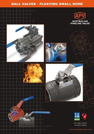
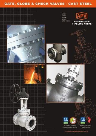
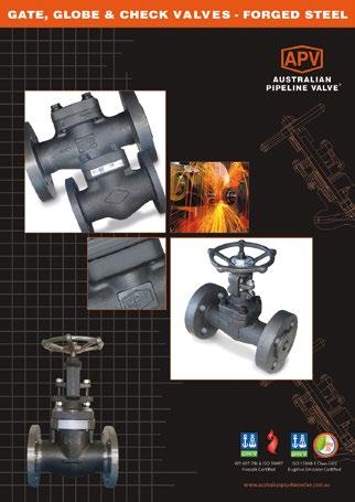
Oilfield Products Valves & Wellheads Gate, Globe & Check Valves - Forged Steel Plug Valves Lubricated, Sleeved & Lined Gate, Globe & Check Valves - Cast Steel Diamond Gear Gearboxes Flowturn Gate, Globe & Check Valves Flowturn Instrument Valves Flowturn Ball Valves Multiway & Deadman Flowturn Strainers & Sight Glasses Supercheck Wafer Check Valves Superseal Butterfly Valves Steamco Steam Valves Superseal Industrial Ball Valves TwinLok Tube Fittings Uniflo Check Valves
Actuators
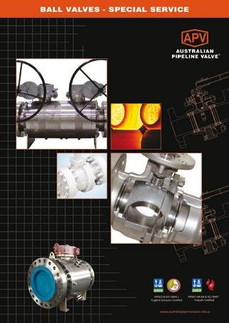
Valves Floating & Trunnion Mounted Ball Valves Floating Small Bore Ball Valves Special Service Product Brochure Contact us for your local stockist/distributor
Torqturn
Ball

API6A CHOKE - H2 & FCV STYLE Australian Pipeline Valve - Installation, Operation and Maintenance Manual 1 Introduction 2 Safety Information 3-4 1.0 Installation H2 & FCV Chokes 4-6 1.1 Installation positions 4 1.2 Preparation for installation 4 1.3 End connections - installation 5-6 2.0 Operation H2 & FCV Chokes 6 3.0 Routine Maintenance H2 Chokes 6-7 4.0 Preventative Maintenance & Repair H2 Chokes 7-11 4.1 Preparation 7 4.2 Disassembly & repair Type H2 adjustable choke 3,000 to 10,000 psi 7-8 4.3 Assembly Type H2 adjustable choke 3,000 to 10,000 psi 8-9 4.4 Servicing/repair Type H2 positive choke 3,000 to 15,000 psi 9-11 5.0 Repair Instructions FCV Series 12-14 6.0 Replacement Parts H2 & FCV Chokes 14-15 6.1 Individual parts 14 6.2 Bonnet assembly 15 6.3 Adaption kits 15 Appendix - API6A Material service categories & rating levels 16-19 Warranty 20 INDEX © Copyright Australian Pipeline Valve 1990 - 2023 Edition Catalogues, photos, brochures and technical publications are the exclusive property of Australian Pipeline Valve. Any unauthorised reproduction in total or in part, shall result in prosecution. Products and data sheets in this publication are subject to change at anytime without notice. Australian Pipeline Valve reserves the right to carry out amendments to products and materials.
INTRODUCTION
The majority of this information is common knowledge to experienced valve & choke users. When properly installed in applications for which they were designed, Australian Pipeline Valve (APV) chokes will give long reliable service. This instruction is only a guide for installation and operation on standard service and covers general maintenance and minor repairs. A professional APV approved engineering facility should be utilised for reconditioning or major repairs.
Note
We do recommend however that this entire document be read prior to proceeding with any installation or repair. Australian Pipeline Valve and it’s parent company take no responsibility for damage or injury to people, property or equipment. It is the sole responsibility of the user to ensure only specially trained valve repair experts perform repairs under the supervision of a qualified supervisor.
RESPONSIBILITY FOR VALVE APPLICATION
The User is responsible for ordering the correct chokes. The user is responsible for ensuring APV Valves are selected and installed in conformance with the current pressure rating and design temperature requirements. Prior to installation, the chokes and nameplates should be checked for proper identification to ensure the choke is of the proper type, material and is of a suitable pressure class and temperature rating to satisfy the requirements of the service application.
Do not use valves in applications where either the pressure or temperature is higher than the allowable working values. Also chokes should not be used in service media if not compatible with the choke material of construction, as this will cause chemical attacks, leakage, choke failure.
RECEIVING INSPECTION AND HANDLING
Valves should be inspected upon receipt to ensure:
- Conformance with all purchase order requirements.
- Correct type, pressure class, size, body and trim materials and end connections.
- Any damage caused during shipping and handling to end connections, hand wheel or stem.
The User is advised that specifying an incorrect choke for the application may result in injuries or property damage. Selecting the correct choke type, rating, material and connections, in conformance with the required performance requirements is important for proper application and is the sole responsibility of the user.
API6A CHOKE - H2 & FCV STYLE Australian Pipeline Valve - Installation, Operation and Maintenance Manual 2
SAFETY INFORMATION
The following general safety information should be taken in account in addition to the specific warnings and cautions specified in this manual. They are recommended precautions that must be understood and applied during operation and maintenance of the equipment covered in this I.O.M
To avoid injury, never attempt to disassemble a choke while there is pressure in the line. Ensure both upstream and downstream pressures are removed. Disassemble with caution in case all pressures are not relieved. Even when replacing stem packing, caution is necessary to avoid possible injury.
To prevent choke bending, damage, inefficient operation, or early maintenance problems, support piping on each side of the choke. Warning, certain gases and fluids could cause damage to human health, the environment or property hence the necessary safety precautions to prevent risk should be taken.
• A choke is a pressurised mechanism containing energised fluids under pressure and consequently should be handled with appropriate care.
• Choke surface temperature may be dangerously too hot or too cold for skin contact.
• Upon disassembly, attention should be paid to the possibility of releasing dangerous and or ignitable accumulated fluids.
• Ensure adequate ventilation is available for service.
This manual provides instructions for storing, general servicing, installation and removal of chokes. APV and it’s resellers refuse any liability for damage to people, property or plant as well as loss of production and loss of income under any circumstances but especially if caused by: Incorrect installation or utilisation of the choke or if the choke installed is not fit for intended purpose. It is the sole responsibility of the user to ensure the choke type and materials are correctly specified.
API6A CHOKE - H2 & FCV STYLE Australian Pipeline Valve - Installation, Operation and Maintenance Manual 3
DURING OPERATION TAKE INTO ACCOUNT THE FOLLOWING WARNINGS:
a- Graphite/Graphoil packing and body gasket is very brittle, any impacting, twisting or bending should be avoided.
b- The choke’s internal parts such as disc, stem, seats, seals, gaskets shall be handled with care avoiding scratches or surface damage.
c- All tools and equipment for handling the internal parts shall be soft coated or else take extreme care, especially on machined mating surfaces and with soft parts.
d- Valves can be fitted with gaskets or seals in PTFE, Buna, Viton, etc., hence high temperatures will damage sealing components.
For all operations make reference to position number on part list of the applicable drawing listed.
1.0 INSTALLATION H2 & FCV
Install choke in system using proper size mating flanges or threaded end connections and appropriate gasket seal rings or thread sealant.
Piping (where applicable) should be properly aligned and supported to reduce mechanical loading on the end connections.
1.1 INSTALLATION POSITIONS
Choke valves are uni-directional and therefore may be installed in the direction of flow indicated on the body.
1.2 PREPARATION FOR INSTALLATION
• Remove protective end caps or plugs and inspect valve ends for damage to threads, socket weld bores or flange faces.
Ensure sufficient clearance for the stem in the full open position may cause the choke to be inoperable. Inadequate clearance for choke may add mechanical loading to the choke ends. Sufficient clearance should be allowed for threaded chokes to be ‘swung’ during installation.
• Thoroughly clean adjacent piping system to remove any foreign material that could cause damage to seating surfaces during valve operation.
• Verify that the space available for installation is adequate to allow the valve to be installed and to be operated.
API6A CHOKE - H2 & FCV STYLE Australian Pipeline Valve - Installation, Operation and Maintenance Manual 4
1.3 END CONNECTIONS
- INSTALLATION
1.3.1 Threaded Ends
Check condition of threads on mating pipe.
Apply joint compound to the male end of joint only. This will prevent compound from entering the choke flowpath.
1.3.2 Flanged Ends
Check to see that mating flanges are dimensionally compatible with the flanges on the choke and ensure sealing surfaces are free of debris.
Install the correct studs and nuts for the application and place the flange gasket between the flange facings.
Stud nuts should be tightened in a an opposing criss-cross pattern in equal increments to ensure proper gasket compression.
1.3.3 Buttweld Ends
Clean the weld ends as necessary and weld into the line using an approved weld procedure. Make sure the pipe and body material given on the nameplate is compatible with the welding procedure.
Chokes under 2” (50 NB) should be lightly closed during welding to prevent damage to the seating surfaces and stem caused by thermal expansion during the weld process.
1.3.4 Choke Installation by Welding
Leave chokes assembled and in the lightly closed position during installation, welding and post-weld heat treatment. This will prevent the valve seat from floating or distorting during the process. After welding completion, open the choke and flush line to clean out any foreign matter. The responsibility for welding of the chokes is that of those performing the welding.
API6A CHOKE - H2 & FCV STYLE Australian Pipeline Valve - Installation, Operation and Maintenance Manual 5
Stem seal leakage could result in personal injury. Choke stem area is tested prior to shipping but may require regreasing (H2 only) or changing to meet specific service conditions.
Personal injury may result from sudden release of any process pressure. APV recommends the use of protective clothing, gloves and eyewear when performing any installation or maintenance.
Isolate the choke from the system and relieve pressure prior to performing maintenance.
Disconnect any operating line providing air pressure, control signals or electrical power to actuators.
Check the stem sealing area for pressurised process fluids even after the choke has been removed from the line, particularly when removing seals, stem bleed or grease plugs..
If a gasket seal is disturbed while removing or adjusting gasketed parts, APV recommends installing a new gasket while reassembling. A proper seal is required to ensure optimum operation.
2.0 OPERATION H2 & FCV
As the choke is opened, numbers will appear, indicating the equivalent orifice setting of the choke, in 64th of an inch or/and percentage open. Once the choke has been set as the desired orifice size, thumbscrew (H2 model only) should be tightened to secure that setting. Flow may now be released through the choke. Should further adjustment be necessary, simply loosen the thumbscrew, turn the handwheel in the direction needed to correct the flow, then re-tighten thumbscrew.
3.0 ROUTINE MAINTENANCE H2
Regularly operate and inspect to ensure the choke functions properly and there is no leakage. Should there be stem area leakage, inject some plastic packing into the stem if the optional plastic injection fitting is provided.
API6A CHOKE - H2 & FCV STYLE Australian Pipeline Valve - Installation, Operation and Maintenance Manual 6
If the choke is to be disassembled while installed in a piping system, it must be isolated from the system pressure and flow. With the choke at an open setting, internal pressure must be bled to 0 psi.
4.0 PREVENTATIVE MAINTENANCE & REPAIR H2
4.1 PREPARATION
Note: It is not necessary to remove the choke from the tree (or the manifold) to perform the procedures outlined below.
1) Close all valves necessary to isolate the choke being serviced from well pressures.
2) Place a warning tag on each valve closed in Step 1 above, to prevent the opening of the valves while maintenance is in progress.
4.2 DISASSEMBLY & REPAIR TYPE H2 ADJUSTABLE CHOKE 3,000 TO 10,000 PSI
4.2.1 Choke Body
a) Ensure that the choke needle is fully retracted.
b) Loosen the bleed plug to vent the body cavity. Slowly loosen the bonnet nut.
c) Once the pressure has been completely bled off, back off the bonnet nut and remove the bonnet assembly.
Never stand in front of the choke when removing the bonnet assembly, always stand to the side. Pressure may be trapped inside the choke. Wear protective eye goggles.
d) Remove the seat assembly.
e) Inspect the following critical areas on the choke body:
i) Bonnet-to-body seal surface: - Ensure that the surface is clean and free from nicks and scratches.
ii) Bore of the choke body that surrounds the bonnet: - Ensure the bore is clean and free from burrs.
iii) Seat threads of the choke body: - This area is susceptible to wear and erosion. The threads should be free from burrs and trash. If the threads are worn or eroded, the body should be returned to APV for repair.
f) Clean the choke body OD threads, seat threads and bonnet bore. Apply a coat of grease to these areas before re-installation.
API6A CHOKE - H2 & FCV STYLE Australian Pipeline Valve - Installation, Operation and Maintenance Manual 7
4.2.2 Bonnet Nut
a) Remove the bonnet nut from the blanking plug/bonnet assembly.
b) Visually inspect the bonnet nut OD and hammer lugs for abuse. If any of the lugs are beaten down into the OD of the nut, the nut should be replaced.
c) Clean the threads with solvent and wire brush. This area is susceptible to wear and corrosion.
d) After inspection, grease threads with heavy grease before re-installation.
4.2.3 Blanking Plug/Bonnet Assembly
a) Inspect the bonnet-to-body seal surface on the OD of the blanking plug/bonnet body. Ensure that the surface is free from burrs or nicks.
b) Inspect the O-ring/bonnet gasket and groove in the bonnet each time the bonnet is removed from the choke body. Remove any nicks or burrs with fine emery cloth.
c) Apply a light coat of grease or heavy oil to seal surface of choke body and an O-ring/bonnet gasket before re-installation.
4.3 ASSEMBLY TYPE H2 ADJUSTABLE CHOKE 3,000 TO 10,000 PSI
4.3.1 Preparation
a) Prior to assembly, all components should be thoroughly cleaned of all debris and lubricants. This includes all threads, holes, grooves and vents.
b) Visually inspect all parts for damage after cleaning, but before assembly.
4.3.2 Bonnet Assembly
a) Lightly grease the O-ring groove and packing bore of the bonnet body. Heavily grease the threads in the bonnet body.
b) Lightly grease the O-ring and install in groove of bonnet body.
c) Place bonnet body on a flat surface with packing bore up. Lubricate the J-Packing and junk rings with light grease or heavy oil. Install the metal junk ring, back-up ring, (part of packing seat), J-Packing, support ring, and retainer ring.
4.3.3 Needle Installation
a) Lubricate the needle threads with heavy grease. Grease the sealing surface with light grease or heavy oil. Place the bonnet on it’s side and slowly slide the needle thread end first, through the packing end of the bonnet body. Engage the threads of the needle with the threads of the bonnet body. Temporarily install handwheel on the needle and install needle in bonnet body by rotating handwheel counter-clockwise. After installation, remove the handwheel.
b) Slide the indicator over the handwheel end of the needle. Install setscrew in the indicator hand tight.
c) Lubricate the threads of the bonnet but with heavy grease. Slide bonnet nut over bonnet body until it bottoms out against the bonnet flange.
d) Rotate bonnet body until the needle locking screw hole faces up. Insert the plug into the hole. Grease and install the needle locking screw into the tapped hole hand tight.
e) Install the handwheel, hex bolt or nut, and washer to needle.
API6A CHOKE - H2 & FCV STYLE Australian Pipeline Valve - Installation, Operation and Maintenance Manual 8
4.3.4 Seat Installation
a) Lubricate the seat threads in the choke body with heavy grease.
b) Inspect the new seats.
c) Ensure the gasket is clean and flat against the should of the seat.
d) Centre the gasket on the seat by bending down the lugs on the gasket.
e) Apply a light coat of grease to the seat threads and gasket.
f) Install the new seat using the appropriate wrench and torque to put 677.9 Nm (500 ft lbs).
The needle should be backed well into the bonnet assembly before installing the bonnet assembly on the choke body to ensure that it does not damage the seat during installation.
g) Lubricate the bonnet seal surface of the choke body with light grease and the bonnet nut threads with a heavy grease.
h) Install bonnet assembly in choke body. Make up bonnet nut hand tight. Using a hammer, tighten the bonnet nut completely.
4.3.5 Calibrating the choke
a) After the bonnet nut is tight, run the needle in against the seat, align the zero setting on the indicator with notch on the bonnet body and tighten the indicator set screw. Do not tighten the bonnet to needle set screw until the choke is positioned at the desired setting.
4.4 SERVICING/REPAIR TYPE H2 POSITIVE CHOKE 3,000 TO 15,000 PSI WP
4.4.1 Preparation
a) Prior to assembly, all components should be thoroughly cleaned of all debris and lubricants. This includes all threads, holes, grooves and vents.
b) Visually inspect all parts for damage after cleaning, but before assembly.
4.4.2 Flow Bean Replacement
Note: The volume of the flow through the positive choke will change depending on the size and condition of the flow bean. Replace the flow bean if it is worn or if another size is required.
Parts Required:
1. Flow bean, appropriate size and material.
2. Flow bean gasket.
a) Using a hammer, loosen the bonnet nut.
b) Remove the blanking plug assembly. The pipe plug, retainer ring, blanking plug and O-ring will come out in the bonnet nut as an assembly.
API6A CHOKE - H2 & FCV STYLE Australian Pipeline Valve - Installation, Operation and Maintenance Manual 9
c) Remove the blanking plug O-ring.
d) Inspect the O-ring for damage. Replace if necessary.
e) Remove the flow bean using the appropriate wrench.
4.4.3 Flow Bean Installation
a) Inspect the new flow bean.
b) Ensure that the gasket is clean and flat against the shoulder of the flow bean.
c) Centre the gasket on the flow bean by bending down the lugs on the gasket.
d) Apply a light coat of grease to the flow bean threads and gasket.
e) Install the new flow bean using the appropriate wrench and torque to 677 Nm (500 ft lbs).
f) Install the O-ring onto the blanking plug.
g) Inspect the body and bonnet nut threads.
h) Apply a light coat of grease to the seal area, the external threads of the choke body and the threads of the bonnet nut.
i) Install the blanking plug assembly onto the choke.
j) Using a hammer, tighten the bonnet nut completely.
API6A CHOKE - H2 & FCV STYLE Australian Pipeline Valve - Installation, Operation and Maintenance Manual 10
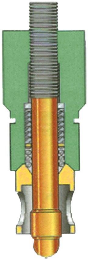
TYPICAL PARTS FOR TYPE ‘H2’ 3,000 – 5,000 PSI
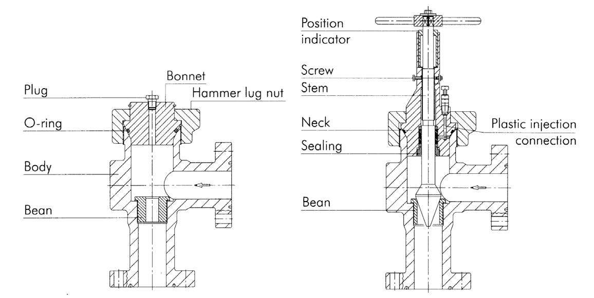
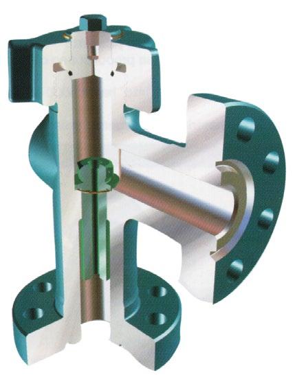
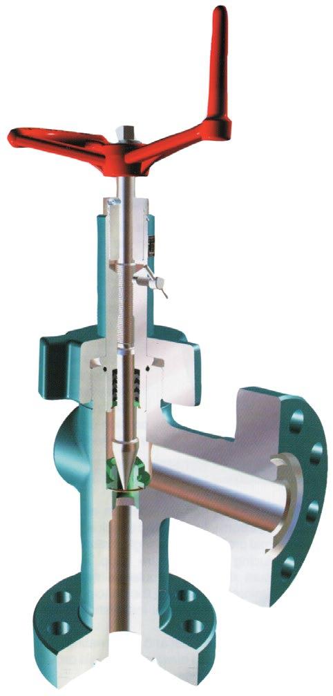
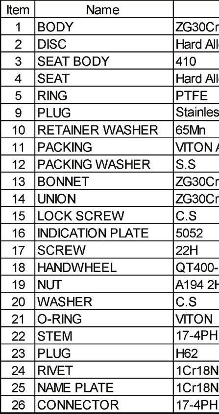
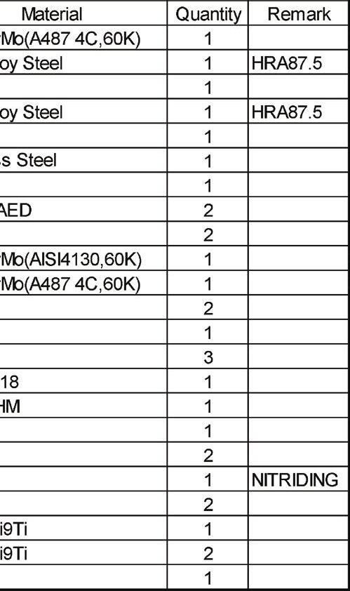
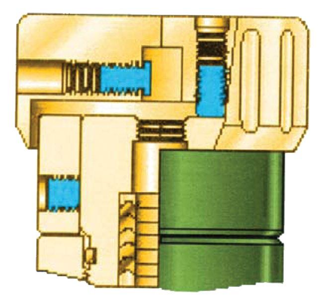
This is an indicative drawing only, parts vary for different sizes, ratings and trim styles.
API6A CHOKE - H2 & FCV STYLE Australian Pipeline Valve - Installation, Operation and Maintenance Manual 11
* Optional CHOKE VALVE 2-1/16 5000 H2 STYLE NameMaterial Quantity Remark Item 1 2 3 4 5 9 10 11 12 13 14 15 16 17 18 19 20 21 22 23 24 25 26 positive variable
5.0 REPAIR INSTRUCTIONS FCV
Redressing the FCV Removing the Trim
Note: Notice that the handle has a notch for setting and reading the adjustment of the valve. Directly above and below this notch (when the valve is closed) are the set screws.
1. Remove the valve from the line.
2. Open the valve two full terms.
3. Bleed all pressure from the valve.

Beware of escaping gas under pressure. Wear eye protection and warn others in the vicinity. Isolate the choke by first closing other valves before removing from the line. Then bleed any remaining pressure from the choke before removing from the line.
3. Remove the locking screw from the handle and loosen the remaining set screws with a allen key wrench.
4. Remove the handle. The primary set screw should be loosened three full turns to clear stem. Remove the flow indicator ring.
5. Use an adjustment spanner with 1/4” diameter pin (Pt.#10525-S) to remove the packing gland, stem, spring, spacer and washers (Figure 2).
API6A CHOKE - H2 & FCV STYLE Australian Pipeline Valve - Installation, Operation and Maintenance Manual 12
2.
FIGURE
1. FIGURE
Removing the Packing
1. Unscrew the stem and remove it from the packing gland. The spacer, spring, and washer will no be free for removal.
2. Push the packing out of the gland with a screwdriver. Remove one or two packing rings at a time until all are removed.
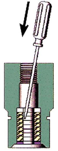
Be very careful not to scratch the packing bore.
Installing the Packing
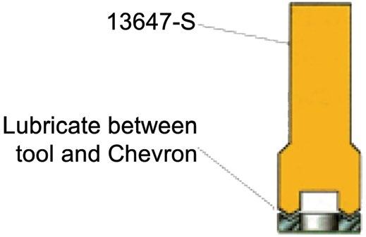
Note: Use special tool 13647-S to install the packing. This tool is customised to exactly fit the packing.
1. Be sure the bore is not scratched or pitted. Grease it with Lubriplate 630AA.
2. Put Lubriplate between each chevron. With the gland upside down, push each packing chevron ring in place.
3. Apply Lubriplate to the end of the 13647-S tool. The Lubpriplate end of the 13647-S will pick up the chevron seals (Figure 4).
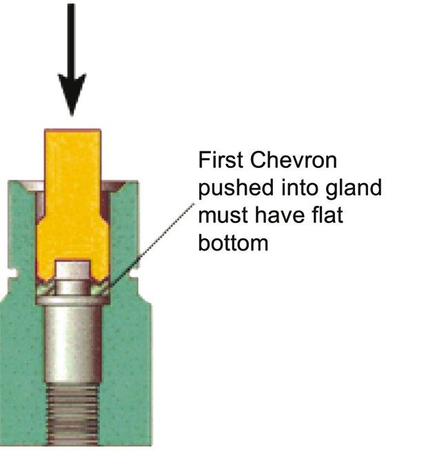
Note: The first chevron seal pushed into the gland must have a flat bottom.
4. Push the chevron seals into the bore one at a time (Figure 5).
API6A CHOKE - H2 & FCV STYLE Australian Pipeline Valve - Installation, Operation and Maintenance Manual 13
FIGURE 3.
FIGURE 4.
FIGURE 5.
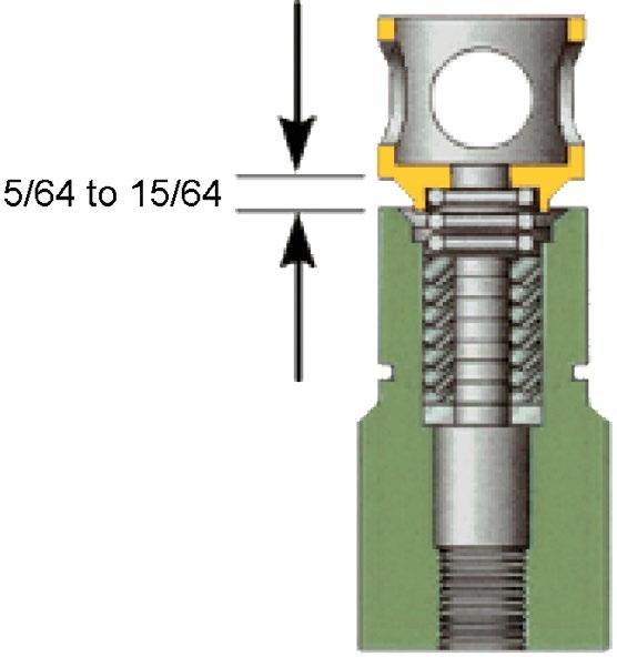
5. Fit the spring washer, spring, and spacer over the packing as shown. Maintain 8/64” to 15/64” spring compression by removing no more than one packing chevron and/or adding spacer washers above or below the spring (Figure 6).
6. Lubriplate the stem and push it through the spacer, spring, spring washer, and packing. Taking care not to damage the stem seating surface, thread the top of the stem into the gland.
Seat & Stem Maintenance
1. Ensure that the stem and seat are lapped and coated with grease.
2. Put the O-ring in the seat using Lubriplate and install it in the body with the O-ring side down.
3. Re-fit handle to the stem with one set screw. Ensure the screw is set on the stem flat. Turn the stem to the full-up position and wipe the O-ring and the O.D. of the gland with grease before screwing the packing gland into the body with an adjustable spanner.
4. Touch the seat with the gland and stop. Unscrew one-half turn. Run the stem down to assume alignment of the seat. Run the stem up two turns and then tighten the gland securely. Run the stem down snug against the seat.
5. Remove the handle and place the indicator ring on the packing gland.
6. Replace the handle. Raise or lower the handle so that it’s bottom edge is even with the zero mark on the indicator. Tighten the first set screw to lock the handle to the stem. Lock the flow indicator ring to the packing gland. Use the second handle set screw to lock the first handle set screw.
6.0 REPLACEMENT PARTS H2 & FCV
APV manufactures a complete line of replacement parts for all our chokes. Available replacement parts include:
6.1 INDIVIDUAL PARTS
• Seats
• Stems
• Bonnets
• Blanking Caps
• Cage Nipples
• Hammer Lug Nuts
• Packing Assemblies
• Flow Beans
• Bean Wrenches
API6A CHOKE - H2 & FCV STYLE Australian Pipeline Valve - Installation, Operation and Maintenance Manual 14
FIGURE 6.
FIGURE 7.
6.2 BONNET ASSEMBLY
• Bonnet
• Stem
6.3 ADAPTION KITS
• Indicator
• Handwheel
(For converting adjustable chokes to positive)
• Blanking Cap
• Retainer
• Seal
• Lug Nut
• Seals & Fittings
• Lug Nut (Optional)
• Flow Bean (Optional)
API6A CHOKE - H2 & FCV STYLE Australian Pipeline Valve - Installation, Operation and Maintenance Manual 15
APPENDIX
API6A MATERIAL SERVICE CATEGORIES & RATING LEVELS
Overview Standards
Australian Pipeline Valve (APV) standards comply with technical specification API-6A. The description for APV equipment consists of a general description, working pressure, temperature rating, material class rating, product specification level (PSL) and performance requirement (PR). These ratings are defined in the following API-6A tables.
To comply with API-6A, APV offers:
- Pressure ratings in psi: 2000, 3000, 5000, 10,000 & 15,000. Temperature ratings: L, P, R, S, T, U, V, X & Y.
- Material class: AA, BB, CC, DD, EE, FF & HH.
- Product specification level: 1, 2, 3 & 4 (PSL 1, 2, 3, 4).
- Performance requirement: 1 & 2.
*See paragraph A5 of API-6A 17a. Ed.
PR1 is standard
PR2 also available (increased cycle times on test required)
- H2 & FCV STYLE Australian Pipeline Valve - Installation, Operation and Maintenance Manual 16
API6A CHOKE
RECOMMENDED MINIMUM PSL FOR PRIMARY PARTS
NACE No YesYes YesNoYes High H2S Concentrate No No YesNoNoYes Close Proximity*NoNoNoYes YesYes Rated Working Pressure, PSI PSL PSL PSL PSL PSL PSL 5,000 1 12213 10,000 2 23334 15,000 and up 3 34444
AA
BB - General Service
CC - General Service
DD - Sour Service
EE - Sour Service
Carbon or low allow steelCarbon or low allow steel
Carbon or low allow steelStainless Steel
Stainless Steel Stainless Steel
Carbon or low allow steelCarbon or low allow steel
Carbon or low allow steelStainless Steel
FF - Sour Service Stainless Steel Stainless Steel
PSL
PSL (PRODUCT
PSL
There are two Performance Requirement Levels, PR1 and PR2. The latter represents more rigorous performance requirements. See API Specification 6A, Section 300 and Section 900.
905 covers valves (905.3 - Flowline Valves, 9.5.5 - Actuated Valves).
API6A CHOKE - H2 & FCV STYLE Australian Pipeline Valve - Installation, Operation and Maintenance Manual 17 API MATERIAL REQUIREMENTS API TEMPERATURE REQUIREMENTS API PRESSURE/TEMPERATURE RATINGS (Y)* MATERIAL CLASS BODY, BONNET & FLANGE
- General Service
MINIMUM MATERIAL REQUIREMENTS PRESSURE CONTROLLING PARTS As per API6A (ISO 10423) 2013: As defined by ISO 15156 (all parts) (NACE MR0175) (See API6A) In compliance with ISO 15156 (all parts) (NACE MR0175) (see API6A) CRA required on retained fluid-wetted surfaces only; CRA cladding of low-alloy or stainless steel is permitted (See API6A) CRA as defined in API6A; ISO 15156 (all parts) (NACE MR0175; see API6A) definition of CRA does not apply a a a a b b b bcd b b b bcd a b c d Fº Cº MIN. MAX.MIN. MAX K-75 to 180-60 to 82 L-50 to 180-46 to 82 P-20 to 180-29 to 82 R* S0 to 140-18 to 60 T0 to 180-18 to 82 U V 0 35 to to 250 250 -18 2 to to 121 121 TEMPERATURE CLASSIFICATION OPERATING RANGE Room Temperature* X* 0to350 -18to177 to 343 Y* 0to650 -18 * No longer referenced in API6A/ISO 10423-2013 N-50 to 140-46 to 60 0 to 250 300350 400 450 500 550 600 650 2000 1955 1905 1860 1810 1735 1635 1540 1430 3000 2930 2860 2785 2715 2605 2455 2310 2145 5000 4880 4765 4645 4525 4340 4090 3850 3575 Rated Working Pressure PSI TEMPERATURE IN ºF * Based on ‘Y’ Temp. Due to elastomers, Gate Valves & Chokes are temp ‘T’ as standard hence consult seperate chart. PSL Material Control is found in API Specification 6A, Specification for Wellhead and Christmas Tree Equipment Section 400 PSL Material Control is found in API Specification 6A, Specification for Wellhead and Christmas Tree Equipment Section 400
HH - Sour Service CRAs CRAs
Section
(PRODUCT SPECIFICATION LEVEL) MATERIAL REQUIREMENTS
SPECIFICATION LEVEL) QUALITY
CONTROL
(PERFORMANCE REQUIREMENTS) LEVELS
API6A TRIM TYPES
TRIM CODE
T-21
STANDARD TRIM
T-22
T-23
T-24
S-24
T-26
T-27
T-36
T-37
TRIM TYPE
For essentially non corrosive liquids or gases. Typical are crude and reined oils, natural or refined gases and processed hydrocarbons. Typical uses are wellheads, manifolds flowlines, and other similar installations requiring a through conduit valve. The temperature limitations are 0º to 250ºF (-17.7ºC to 121ºC)
STAINLESS TRIM
For substantially the same service as T-21 but where the corrosion resistance of 13% Chrome Stainless Steel internal parts are desirable. Also usable for mildly corrosive fluids and gases where limited corrosion of the internal body surfaces can be tolerated. The temperature limitations are 0º to 250ºF (-17ºC to 121ºC). Recommended when partial pressure of CO2 is greater than 7.3.
FULL STAINLESS STEEL TRIM
For any liquid or gaseous product for which the resistance of the 13% Chrome Stainless is adequate. Also used where the resistance of Stainless Steel is desirable from the standpoint of product purity. The temperature limitations are 0º to 250ºF (-17.7ºC to 121ºC). Recommended when partial pressure of CO2 is greater than 30.
SOUR GAS & OIL
Primarily for sour gas and oil where resistance to Hydrogen Sulfide embrittlement is required. Also suitable for other chemicals, products or hydrocarbons when H2S is present. May be used when CO2 is present in smaller amount then H2S. The temperature limitations are 0º to 250ºF (-17.7ºC to 121ºC)
STAINLESS SOUR GAS AND OIL TRIM
Primarily for sour gas and oil when the CO2 exceeds the H2S content. It is intended to provide resistance to the metal loss type of corrosion usually associated with CO2, plus resistance to Hydrogen Sulphide embrittlement. The temperature limitations are 0º to 250ºF (-17.7ºC to 121ºC)
WATERFLOW (UNINHIBITED)
Primarily for use in untreated or uninhibited brackish saline water typically associated with oilfield waterflood projects and/or disposal wells in which the internal plastic coating of the body surfaces provides resistance to salt water corrosion. The internal parts are also resistant to Sulfide embrittlement and corrosion. The temperature limitation are 0º to 250ºF (-17.7ºC to 121ºC)
LOW TEMPERATURE – STANDARD TRIM – GENERAL OILFIELD
For essentially non-corrosive liquids or gases. Typical examples are crude and refined oils, natural or refined gases and processed hydrocarbons. Typical uses are wellheads, manifolds, flowlines and other similar installations requiring a through conduit valve. The temperature limitations are -50º to 180ºF. (-45ºC to 82ºC)
LOW TEMPERATURE – SOUR GAS AND OIL
Primarily for sour gas and oil where resistance to Hydrogen Sulphide embrittlement is required. Also suitable for other chemicals, products or hydrocarbons where H2S is present. May be used when CO2 is present in smaller amounts than H2S. The temperature liitations are -50ºC to 180º F (-45ºC to 82ºC) SPECIAL
API6A CHOKE - H2 & FCV STYLE Australian Pipeline Valve - Installation, Operation and Maintenance Manual 18
TRIMS AND TEMPERATURE RANGES AVAILABLE UPON REQUEST
S-37 API SPEC, 6A RETAINED FLUID RATING AA BB CC DD EE FF AA DD EE
VALVE TRIM CHART FOR API6A GATE & CHOKE VALVES
API6A TEMPERATURE CLASS P: SERVICE -20°F TO 180°F (-29°C TO 82°C)
This list is provided as a guide only Australian Pipeline Valve reserves the right to provide alternatw materials without prior notice
API6A CHOKE - H2 & FCV STYLE Australian Pipeline Valve - Installation, Operation and Maintenance Manual 19 BODY & BONNET BONNET SEAL NEEDLE/ DISC/BEAN SEAT STEM TRIM SERVICE MATERIALS Waterflood T27 EE 2,000 3,000 5,000 API 60K Alloy Steel w/Plastic Coat SS 17-4PH PRESSURE RATING PSI API MATERIAL CLASS 4130 w/QPQ 4130 w/TFE2 4130 w/MDC5 17-4PH w/TFE2 General Moderately Corrosive CO2 T22BB Carbon or Low Allow Steel SS 2,000 3,000 5,000 General Oilfield Gas, Oil T21AA Carbon or Low Allow Steel CS 2,000 3,000 5,000 410410 17-4PH w/MDC5 410 410 w/TFE2 17-4PH w/MDC5 SS Sour (H2S) Service NACE4 MR01-75 T24 DD API 60K Alloy Steel SS 2,000 3,000 5,000 General Moderately Corrosive CO2 T23CC API 60K CA6NM Stainless Steel Sour (H2S) Service NACE4 MR01-75 S24 EE API 60K Alloy Steel SS 410 w/TFE2 17-4PH w/MDC5 2,000 3,000 5,000 4130 w/TFE2 17-4PH w/MDC5 4130 or 17-4PH Nitrided 2,000 3,000 5,000 4130 or 17-4PH Nitrided SS 4130 4130 w/TFE2 17-4PH w/MDC5 17-4PH 17-4PH w/TFE2 17-4PH w/MDC5 17-4PH w/MDC5 CS API 6A TEMPERATURE CLASS L: SERVICE -50ºF TO 180ºF (-46ºC TO 82ºC) 2,000 3,000 5,000 API 60K Alloy Steel Corrosive (CO2) & Sour (H2S) NACE4 MR01-75 T26FF 2,000 3,000 5,000 API 60K CA6NM Stainless Steel General Oilfield Gas, Oil T36AA 2,000 3,000 5,000 API 60K Alloy Steel 17-4PH w/MDC5 Sour (H2S) Service NACE4 MR01-75 S37 EE 2,000 3,000 5,000 API 60K Alloy Steel SS 17-4PH 4130 w/TFE2 17-4PH w/MDC5 SS 4130 4130 w/TFE2 Sour (H2S) Service NACE4 MR01-75 T37 DD 1 QPQ NITRIDE 2 TFE TEFLON 3 HF6 STELLITE #6 4 CHARPY V NOTCH IMPACT TEST
MDC MOLYBDENUM DISULFIDE COATING
5
WARRANTY
1. LIMITED WARRANTY: Subject to the limitations expressed herein, Seller warrants that products manufactured by Seller shall be free from defects in design, material and workmanship under normal use for a period of one (1) year from installation but in no case shall the warranty period extend longer than eighteen months from the date of sale. This warranty is void for any damage caused by misuse, abuse, neglect, acts of God, or improper installation. For the purpose of this section, “Normal Use” means in strict accordance with the installation, operation and maintenance manual. The warranty for all other products is provided by the original equipment manufacturer.
2. REMEDIES: Seller shall repair or replace, at its option, any non-conforming or otherwise defective product, upon receipt of notice from Buyer during the Manufacturer’s warranty period at no additional charge. SELLER HEREBY DISCLAIMS ALL OTHER EXPRESSED OR IMPLIED WARRANTIES, INCLUDING, WITHOUT LIMITATION, ALL IMPLIED WARRANTIES OF MERCHANTABILITY AND FITNESS OR FITNESS FOR A PARTICULAR PURPOSE.
3. LIMITATION OF LIABILITY: UNDER NO CIRCUMSTANCES SHALL EITHER PARTY BE LIABLE TO THE OTHER FOR INCIDENTAL, PUNITIVE, SPECIAL OR CONSEQUENTIAL DAMAGES OF ANY KIND. BUYER HEREBY ACKNOWLEDGES AND AGREES THAT UNDER NO CIRCUMSTANCES, AND IN NO EVENT, SHALL SELLER’S LIABILITY, IF ANY, EXCEED THE NET SALES PRICE OF THE DEFECTIVE PRODUCT(S) PURCHASED DURING THE PREVIOUS CONTRACT YEAR.
4. LABOR ALLOWANCE: Seller makes NO ADDITIONAL ALLOWANCE FOR THE LABOR OR EXPENSE OF REPAIRING OR REPLACING DEFECTIVE PRODUCTS OR WORKMANSHIP OR DAMAGE RESULTING FROM THE SAME.
5. RECOMMENDATIONS BY SELLER: Seller may assist Buyer in selection decisions by providing information regarding products that it manufacturers and those manufactured by others. However, Buyer acknowledges that Buyer ultimately chooses the product’s suitability for its particular use, as normally signified by the signature of Buyer’s technical representative. Any recommendations made by Seller concerning the use, design, application or operation of the products shall not be construed as representations or warranties, expressed or implied. Failure by Seller to make recommendations or give advice to Buyer shall not impose any liability upon Seller.
6. EXCUSED PERFORMANCE: Seller will make a good faith effort to complete delivery of the products as indicated by Seller in writing, but Seller assumes no responsibility or liability and will accept no back-charge for loss or damage due to delay or inability to deliver, caused by acts of God, war, labor difficulties, accidents, inability to obtain materials, delays of carriers, contractors or suppliers or any other causes of any kind whatever beyond the control of Seller. Under no circumstances shall Seller be liable for any special, consequential, incidental, or indirect damages, losses, or expense (whether or not based on negligence) arising directly or indirectly from delays or failure to give notice of delay.
API6A CHOKE - H2 & FCV STYLE Australian Pipeline Valve - Installation, Operation and Maintenance Manual 20
Australian Pipeline Valve - Installation, Operation and Maintenance Manual 21 NOTES

www.australianpipelinevalve.com.au AUSTRALIAN PIPELINE VALVE® HEAD OFFICE 70-78 Stanbel Road Salisbury Plain South Australia 5109 Telephone +61 (0)8 8285 0033 email: admin@australianpipelinevalve.com.au If you have any requirements in the field of valves, please contact us for a prompt response. Continuous development of Australian Pipeline Valve products may necessitate changes in the design or manufacture process. Australian Pipeline Valve reserves the right to effect any such changes without prior notice. © Australian Pipeline Valve 1990 - 2024 Edition LOCAL DISTRIBUTOR/AGENT IOM APV Choke
