


www.australianpipelinevalve.com.au INSTALLATION, OPERATION & MAINTENANCE MANUAL API6A SLAB GATE VALVE M & HM STYLE
COMPLETE PRODUCT LINE
“Australian Pipeline Valve produces isolation, control and flow reversal protection products for severe and critical service media in utility, steam, pipelines, oil & gas and process industries. APV valves and pipeline products form the most competitive portfolio in the market.”


View our catalogues at www.australianpipelinevalve.com.au AUSTRALIAN PIPELINE VALVE BRAND RANGE - CATALOGUES APV FAMILY OF BRANDS RANGE - CATALOGUES
Oilfield Products Valves & Wellheads Gate, Globe & Check Valves - Forged Steel Plug Valves Lubricated, Sleeved & Lined Gate, Globe & Check Valves - Cast Steel Diamond Gear Gearboxes Flowturn Gate, Globe & Check Valves Flowturn Instrument Valves Flowturn Ball Valves Multiway & Deadman Flowturn Strainers & Sight Glasses Supercheck Wafer Check Valves Superseal Butterfly Valves Steamco Steam Valves Superseal Industrial Ball Valves TwinLok Tube Fittings Uniflo Check Valves
Actuators
Valves Floating & Trunnion Mounted Ball Valves Floating Small Bore Ball Valves Special Service Product Brochure Contact us for your local stockist/distributor
Torqturn
Ball

Introduction 3 Safety Information 4-5 1.0 Installation Model M & HM 5-7 1.1 Installation positions 5 1.2 Preparation for installation 5 1.3 End connections - installation 6-7 2.0 Overview Model M & HM 7-8 2.1 Features & benefits 8 3.0 Operation Model M & HM 9 4.0 Gate Valve Features Model M & HM 9-12 4.1 Rugged & dependable proven design 10-11 4.2 Field proven design features 11-12 5.0 Installation & Operation Model M & HM 13 5.1 Introduction 13 5.2 Installation instructions 14 5.3 Operating instructions 14 6.0 Maintenance Model M & HM 14-18 6.1 Maintenance equipment 15 6.2 Identification & servicing of fittings 15-16 6.3 Stem bearing lubrication 16 6.4 Body lubrication 16-17 6.5 Stem packing 17 API6A SLAB GATE VALVE - M & HM STYLE INDEX Australian Pipeline Valve - Installation, Operation and Maintenance Manual 1

6.6 Venting and draining 18 6.7 Regular preventative maintenance 18 7.0 Troubleshooting Model M & HM 19 Appendix 1 - Model M parts list 20 Appendix 2 - API6A Material service categories & rating levels 20-24 API6A SLAB GATE VALVE - M & HM STYLE INDEX Australian Pipeline Valve - Installation, Operation and Maintenance Manual 2 © Copyright Australian Pipeline Valve 1990 - 2014 Edition Catalogues, photos, brochures and technical publications are the exclusive property of Australian Pipeline Valve. Any unauthorised reproduction in total or in part, shall result in prosecution. Products and data sheets in this publication are subject to change at anytime without notice. Australian Pipeline Valve reserves the right to carry out amendments to products and materials.
INTRODUCTION
The majority of this information is common knowledge to experienced valve users. When properly installed in applications for which they were designed, Australian Pipeline Valve (APV) valves will give long reliable service. This instruction is only a guide for installation and operation on standard service and covers general maintenance and minor repairs. A professional APV approved valve engineering facility should be utilised for reconditioning or major repairs.
We do recommend however that this entire document be read prior to proceeding with any installation or repair. Australian Pipeline Valve and it’s parent company take no responsibility for damage or injury to people, property or equipment. It is the sole responsibility of the user to ensure only specially trained valve repair experts perform repairs under the supervision of a qualified supervisor.
RESPONSIBILITY FOR VALVE APPLICATION
The User is responsible for ordering the correct valves. The user is responsible for ensuring APV Valves are selected and installed in conformance with the current pressure rating and design temperature requirements. Prior to installation, the valves and nameplates should be checked for proper identification to ensure the valve is of the proper type, material and is of a suitable pressure class and temperature rating to satisfy the requirements of the service application.
Do not use valves in applications where either the pressure or temperature is higher than the allowable working values. Also valves should not be used in service media if not compatible with the valve material of construction, as this will cause chemical attacks, leakage, valve failure.
RECEIVING INSPECTION AND HANDLING
Valves should be inspected upon receipt to ensure:
- Conformance with all purchase order requirements.
- Correct type, pressure class, size, body and trim materials and end connections.
- Any damage caused during shipping and handling to end connections, hand wheel or stem.
The User is advised that specifying an incorrect valve for the application may result in injuries or property damage. Selecting the correct valve type, rating, material and connections, in conformance with the required performance requirements is important for proper application and is the sole responsibility of the user.
API6A SLAB GATE VALVE - M & HM STYLE Australian Pipeline Valve - Installation, Operation and Maintenance Manual 3
Note
SAFETY INFORMATION
The following general safety information should be taken in account in addition to the specific warnings and cautions specified in this manual. They are recommended precautions that must be understood and applied during operation and maintenance of the equipment covered in this I.O.M
Never attempt to disassemble a valve while there is pressure in the line. Ensure both upstream and downstream pressures are removed. Disassemble with caution in case all pressures are not relieved. Even when replacing stem packing, caution is necessary to avoid possible injury.
To prevent valve bending, damage, inefficient operation, or early maintenance problems, support piping on each side of the valve. Warning, certain gases and fluids could cause damage to human health, the environment or property, hence the necessary safety precautions to prevent risk should be taken.
• A valve is a pressurised mechanism containing energised fluids under pressure and consequently should be handled with appropriate care.
• Valve surface temperature may be dangerously too hot or too cold for skin contact.
• Upon disassembly, attention should be paid to the possibility of releasing dangerous and or ignitable accumulated fluids.
• Ensure adequate ventilation is available for service.
This manual provides instructions for storing, general servicing, installation and removal of gate valves. APV and it’s resellers refuse any liability for damage to people, property or plant as well as loss of production and loss of income under any circumstances but especially if caused by: Incorrect installation or utilisation of the valve or if the valve installed is not fit for intended purpose. It is the sole responsibility of the user to ensure the valve type and materials are correctly specified.
Australian Pipeline Valve - Installation, Operation and Maintenance Manual4 4 API6A SLAB GATE VALVE - M & HM STYLE
DURING OPERATION TAKE INTO ACCOUNT THE FOLLOWING WARNINGS:
a- Graphite/Graphoil packing and body gasket is very brittle, any impacting, twisting or bending should be avoided.
b- The valve’s internal parts such as disc, stem, seats, seals, gaskets shall be handled with care avoiding scratches or surface damage.
c- All tools and equipment for handling the internal parts shall be soft coated or else take extreme care, especially on machined mating surfaces and with soft parts.
d- Valves can be fitted with gaskets or seals in PTFE, Buna, Viton, etc., hence high temperatures will damage sealing components.
For all operations make reference to position number on part list of the applicable drawing listed.
1.0 INSTALLATION M & HM
Where applicable, piping should be properly aligned and supported to reduce mechanical loading on the end connections.
1.1 INSTALLATION POSITIONS
Gate valves are usually bi-directional and therefore may be installed in either direction. In some cases, gate valves may be uni-directional, in which case the direction of flow will be indicated on the valve body (See section 2.0).
1.2 PREPARATION FOR INSTALLATION
• Remove protective end caps or plugs and inspect valve ends for damage to threads, socket weld bores or flange faces.
• Thoroughly clean adjacent piping system to remove any foreign material that could cause damage to seating surfaces during valve operation.
• Verify that the space available for installation is adequate to allow the valve to be installed and to be operated.
Ensure sufficient clearance for the stem in the full open position may cause the valve to be inoperable. Inadequate clearance for valve may add mechanical loading to the valve ends. Sufficient clearance should be allowed for threaded valves to be ‘swung’ during installation.
Australian Pipeline Valve - Installation, Operation and Maintenance Manual 5 API6A SLAB GATE VALVE - M & HM STYLE
API6A SLAB GATE VALVE - M & HM STYLE
1.3 END CONNECTIONS - INSTALLATION
1.3.1 Threaded Ends
Check condition of threads on mating pipe.
Apply joint compound to the male end of joint only. This will prevent compound from entering the valve flowpath.
1.3.2 Flanged Ends
Check to see that mating flanges are dimensionally compatible with the flanges on the choke and ensure sealing surfaces are free of debris.
Install the correct studs and nuts for the application and place the flange gasket between the flange facings.
Stud nuts should be tightened in a an opposing criss-cross pattern in equal increments to ensure proper gasket compression.
1.3.3 Buttweld Ends
Clean the weld ends as necessary and weld into the line using an approved weld procedure. Make sure the pipe and body material given on the nameplate is compatible with the welding procedure.
1.3.4 Valve Installation by Welding
Leave valves assembled and in the lightly closed position during installation, welding and post-weld heat treatment. This will prevent the valve seat from floating or distorting during the process. After welding completion, open the valve and flush line to clean out any foreign matter.
Stem seal leakage could result in personal injury. Valve stem area is tested prior to shipping but may require extra sealant.
Australian Pipeline Valve - Installation, Operation and Maintenance Manual 6
Personal injury may result from sudden release of any process pressure. APV recommends the use of protective clothing, gloves and eyewear when performing any installation or maintenance.
Isolate the valve from the system and relieve pressure prior to performing maintenance.
Disconnect any operating line providing air pressure, control signals or electrical power to actuators.
Check the stem sealing area for pressurised process fluids even after the valve has been removed from the line, particularly when removing packing seals, or stem bleed or grease fittings.
If a gasket seal is disturbed while removing or adjusting gasketed parts, APV recommends installing a new gasket while reassembling. A proper seal is required to ensure optimum operation.
2.0 MODEL M & HM OVERVIEW
APV API6A Gate Valves are integral body, parallel sided gate valves that are available in solid slab with a floating seat (Model FC) where the sealing force supplied by line pressure, or in expanding self energised slab (Model M & HM). Most models are bi-directional however, a preferred direction may be shown on the valve body for some models.
The Type ‘M’, ‘HM’, and ‘FC’ Gate Valves are proven designs that have been standard in the oil field for more than forty years. Because of APV’s commitment to quality and the reliability of these standard designs, these valves can be maintained anywhere in the world, even in the most remote locations, without having to procure hard to find parts.
Available from 1 13/16” to 7 1/16” and from 2,000 psi to 15,000 psi working pressures.
Australian Pipeline Valve - Installation, Operation and Maintenance Manual 7 API6A SLAB GATE VALVE - M & HM STYLE
2.1 FEATURES AND BENEFITS

Minimal torque: Upper and lower bearings are used to minimize operating stem torque and are isolated from well fluids to increase durability.
Bi-directional seals: The one piece, parallel sided (Model FC) slab gate seals on a floating seat. The sealing force is supplied by line pressure. The expanding type self energised slab (Model M & HM) seals on both seats.
Metal to metal stem back seat: The gate stem has a bevelled shoulder which allows for metal-tometal sealing to the bonnet seat.
Full through conduit: The full through conduit I.D. provides smooth flow with minimal turbulence as well as providing an unobstructed passage for well intervention tools.
Replaceable gate and seats: Gate and seats are field-replaceable.
Re-energizeable Stem Packing: The stem packing can be re-energized by injection plastic sealant in between the packing stacks.
Stem packing replaceable with valve under pressure: The bonnet stem to back-seat seal allows the stem packing to be replaced with the valve under pressure.
Grease fitting: The valve body may be greased through the fitting provided in the valve bonnet.

Australian Pipeline Valve - Installation, Operation and Maintenance Manual 8 API6A SLAB GATE VALVE - M & HM STYLE
3.0 OPERATION M & HM
To close the valve: Rotate the handwheel clockwise, the gate will move downward to the bottom of the valve body, then rotate the handwheel counter-clockwise one half of a rotation to permit the gate movement under pressure. Do not “cheat”.
To open the valve: Rotate the handwheel counter-clockwise until the gate stops at the bonnet.
To close the valve: Rotate the handwheel clockwise until the gate stops at the bottom.
4.0 FEATURES M & HM
Full bore through-conduit: The through-conduit design of the model “M” & “HM” gives a full round bore. Destructive turbulence is eliminated.
Seals without lubrication: Model “M” & “HM” gate valves do not require lubrication for positive sealing in normal operation. Lubrication can be employed as an emergency measure to help effect a temporary seal in the event the gate or seals have become damaged by foreign matter in the valve.
Two safety-capped grease fittings are provided so that the entire valve body can be filled with grease.
Repackable under pressure: APV plastic stem packing can be added to the packing box while the valve is under pressure.
Australian Pipeline Valve - Installation, Operation and Maintenance Manual 9 API6A SLAB GATE VALVE - M & HM STYLE
API6A SLAB GATE VALVE - M & HM STYLE
Seat inserts give double seal: Seat inserts of PTFE (tetrafluoroethylene resin) give an initial PTFE-tometal seal in addition to the metal-to-metal seal which is obtained when the gate assembly is fully expanded. All metal to metal stellite faced seating also available.
TRIM TYPES

General Service (B)
General Service (C)
Sour Service (D) Meets
Sour Service (E) Slightly corrosive H2S (Low CO2)
Sour Service mod. (H) to highly corrosive (High CO2 + H2S)
Sour Service mod. to highly corrosive and chlorides (High H2S high CO2)
*Hydrogen sulphide partial pressure (in psi a) as defined by NACE MR - 01 - 75
**Partial pressure of carbon dioxide (in psi a).
Formula: Partial pressure (PP) = well pressure (psi) X percent of constituent in total well fluid X 1/100
Example: CO2 PP= 3000 psi X 4% x 1/100 = 120 psi*
Material must be chosen to resist CO2 weight loss corrosion.
4.1 RUGGED & DEPENDABLE PROVEN DESIGN
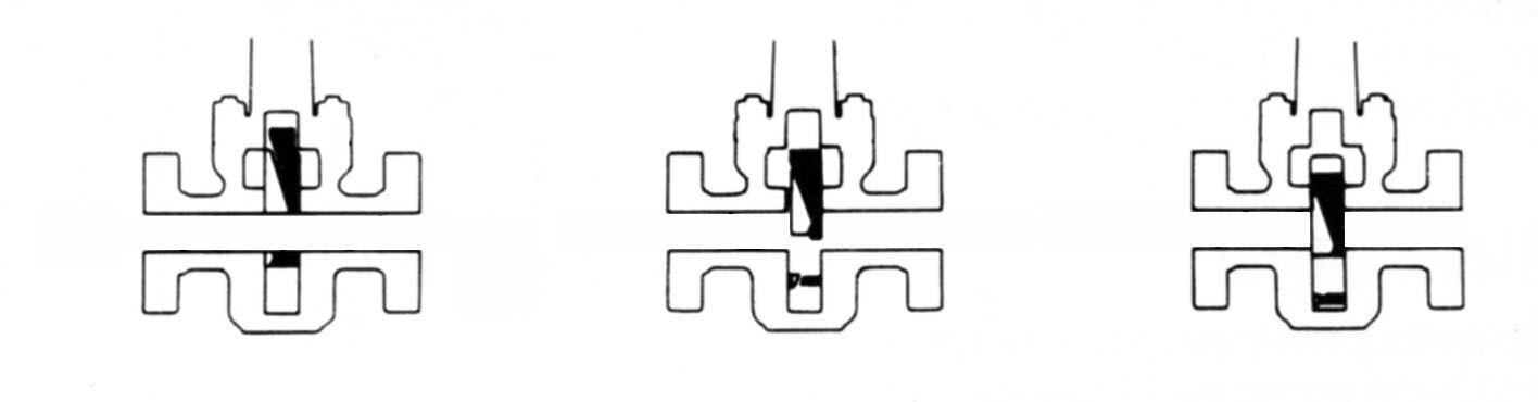
The APV API6A valve is designed for the primary control of high pressure gas and fluid. The valve is a through-conduit type allowing positive closure of the full bore. In both the open/close positions the expanding gate is forced into contact with the seats by the wedging force derived from the design of the gate.
The gate assembly design is a two-piece design with the stem to gate interface on the gate major segment sub-assembly. The gate assembly is bored with the port size, and milled with the “V” surface to accommodate the minor segment sub-assembly.
The gate assembly design uses the “V” to force the two segments out and into contact with the seats as shown in the illustration. The lateral travel generated with this design promotes a complete seal between the seat and gate. This feature promotes the use of this valve in all pressure ranges when a positive seal is required with no pressure assisting the closure.
Australian Pipeline Valve - Installation, Operation and Maintenance Manual 10
Application *H2S **CO2Fluid Class General Service (A) Non Corrosive <0.05<7AA
MODEL M
Slightly corrosive
CO2) <0.057 to 30 BB
(Low
Moderately
<0.05>30 CC
to highly corrosive (High CO2)
Nace
<0.05<7DD
MR-0175 H2S
<0.057
EE
to 30
<0.05>30 FF
<0.05>30
HH

CONCEPT OF EXPANDING GATE (MODEL M & HM)
(Solid Floating Gate also available type FC)
4.2 FIELD PROVEN DESIGN FEATURES
Integral cast steel body of the valve meets or exceed the API Standard 6A and NACE MR-01-75 requirements. Forged body also available.
Bonnet on the valve uses standard field service tools for valve maintenance.
External grease fitting to ensure easy access for lubrication.
Coated stems for reduced friction. High Efficiency Thrust Bearings are used to reduce torque to a minimum.
Secondary plastic packing injection port for emergency pack-off.
Auxiliary operators are easily installed.
Expanding gate assembly ensures a positive seal. The M series valve offer a dual sealing design with an elastomeric low pressure seal in addition to metal-to-metal high pressure sealing. All metal to metal stellite faced seating also available. Floating seated style with pressure energised solid slab is also available (Type FC).
Seat design eliminates the seat from being displaced from the pocket by high pressure. The seats are field replaceable without moving the valves from the tree.
Trims available for eight standard service environments. Special trims are available on request from APV to meet the most demanding environments.

Australian Pipeline Valve - Installation, Operation and Maintenance Manual 11 API6A SLAB GATE VALVE - M & HM STYLE
MODEL M
EXPANDING SEAL

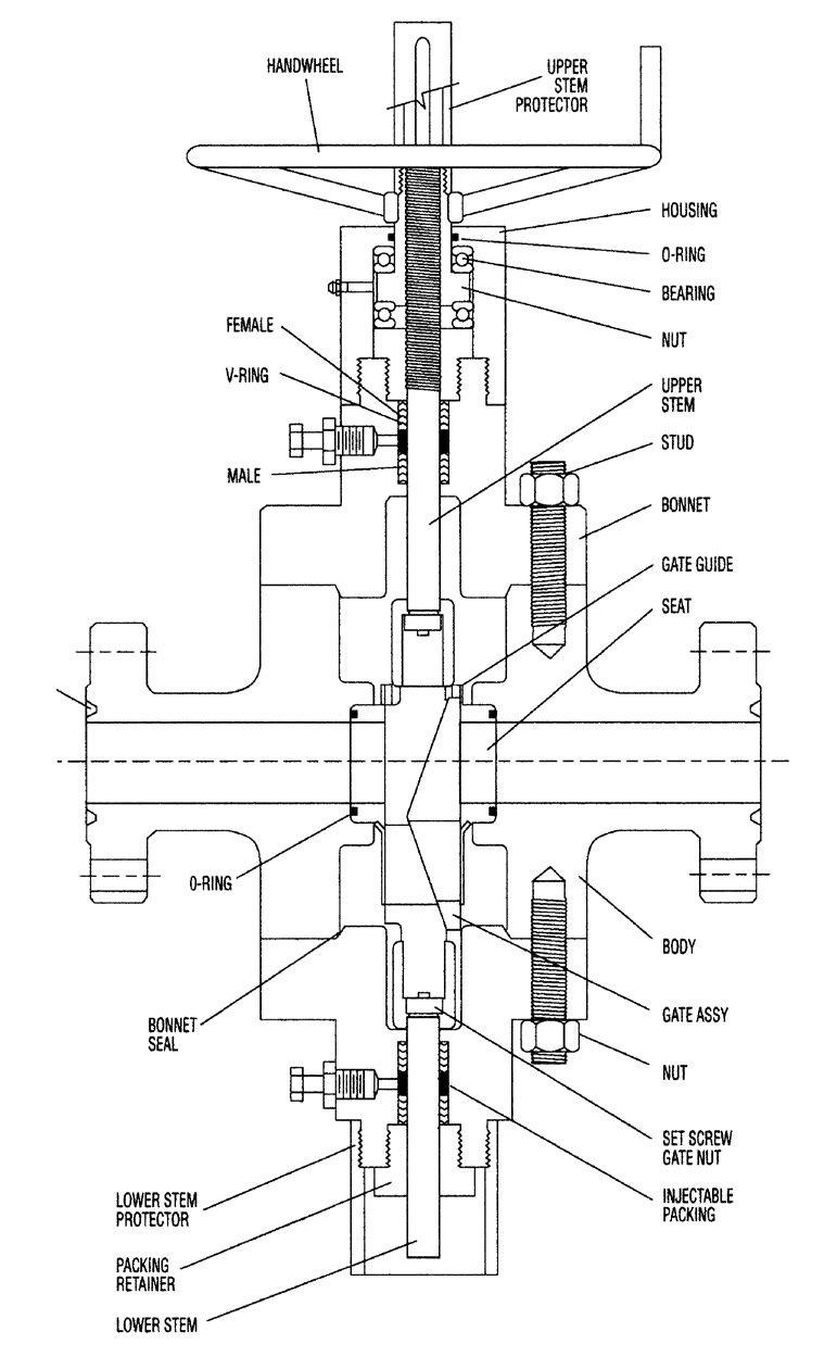


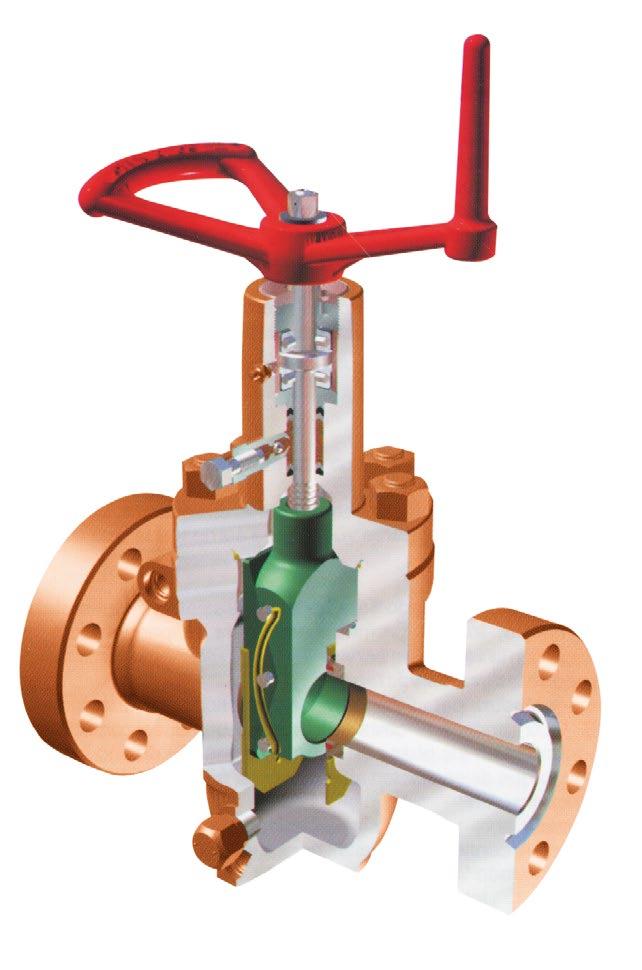
Australian Pipeline Valve - Installation, Operation and Maintenance Manual 12 API6A SLAB GATE VALVE - M & HM STYLE HANDWHEEL UPPER STEM PROTECTOR HOUSING O-RING BEARING NUT UPPER STEM STUD BONNET GATE GUIDE SEAT FEMALE V-RING MALE RING GROOVE O-RING BONNET SEAL LOWER STEM PROTECTOR PACKING RETAINER LOWER STEM BODY GATE ASSY NUT SET SCREW GATE NUT INJECTABLE PACKING
MODEL M Working pressure: 2,000, 3,000 and 5,000 psi
BEARING GREASE FITTING BODY GREASE FITTING PACKING INJECTION FITTING
MODEL HM Working pressure: 10,000, and 5,000 psi Indicative drawing only, design will vary according to size and rating.
5.0 INSTALLATION & OPERATION M & HM
5.1 INTRODUCTION
‘M’ and ‘HM’ Style Gate Valve for working pressures 3,000 through 5,000 (Figure 1).
Manually controlled valves are standard with expanding split gate style along with non-rising stems. Fittings are supplied for body lubrication, bearing lubrication as well as restoration of stem packing. The particular wedging motion of the gate offers a positive mechanical gate seat seal on both the upstream and downstream sides of the valve; however, the valve incorporates a preferred direction of installation. The best course of flow is clearly marked by having an arrow on the valve body.
‘HM’ Style Gate Valve for working pressures 10,000 through 15,000 (Figure 2).
Manually controlled valves are standard with expanding split gate style along with pressure balancing stems. Fittings are supplied for body lubrication, seat lubrication, bearing lubrication as well as restoration of stem packing. The particular wedging motion of the gate offers a positive mechanical gate seat seal on both the upstream and downstream sides of the valve; however, the valve incorporates a preferred direction of installation. The best course of flow is clearly marked by having an arrow on the valve body.


The standard configuration for an actuated valve includes a slab gate, floating seats and a blind bonnet in place of the lower bonnet on manually operated valves. Actuator/bonnet assemblies and actuated valve assemblies also include an optional manual override device.
Australian Pipeline Valve - Installation, Operation and Maintenance Manual 13 API6A SLAB GATE VALVE - M & HM STYLE
FIGURE 1 ‘M’
FIGURE 2 ‘HM’
5.2 INSTALLATION INSTRUCTIONS
As soon as an APV gate valve has been assembled as well as tested it is thoroughly lubricated. A protective coating is put on all flange seal surfaces and threads exposed to the environment. Lubricants such as Molybdenum Disulfide, Xylan, etc., are used to coat gates, seats, stems and other internal parts before assembly. It is very important to preserve the protective coatings and lubricants before installation.
In order to avoid damage to gate and seat sealing surfaces, all valves are shipped in the open position. The valve needs to be left in the open position until installation is complete. If it is necessary to transport the valve, it must always be put into the open position.
When a hydrostatic test is conducted before installation, the valve cavity needs to be drained of test fluids and refilled using suitable lubricant. CAUTION: If hydrostatic tests that exceed the working pressure are needed, they have to be performed whilst the valve is in the open or partially open position.
5.3 OPERATING INSTRUCTIONS
APV slab gate valves have to be fully open or closed to correctly wedge the gate segments up against the seats. Once fully opened or closed, do not back off on the handwheel. The process will release the mechanical wedging action of the gate segments. The required number of turns to operate each APV valve is shown in Table 1 and Table 2.
6.0 MAINTENANCE M & HM
When shipped, all APV valves are fully lubricated and serviced. Once installed, well cleaned up, cementing operations, hydrofrac, acidizing, etc., can move lubricants from the body cavity. This could leave particles and fluid which is often damaging to the gate and seat sealing surfaces. It is strongly recommended to empty, vent and lubricate valves after such operations.
A routine procedure of draining the valve body is a great way to increase the efficient life of the valve. At the very least lubrication upkeep will certainly improve the life of the valve and ensure trouble free
Australian Pipeline Valve - Installation, Operation and Maintenance Manual 14 API6A SLAB GATE VALVE - M & HM STYLE Nominal Size (inches) No. of Turns Nominal Size (inches) No. of Turns 2 1/16" 13 1 13/16" 12 2 9/16" 16 2 1/16" 14 3 1/8" 20 2 9/16" 15 4 1/16" 25 3 1/16" 18 5 1/8" 31 4 1/16" 23 7 1/16" 42
'M' 3,000 Through 5,000 WP
'HM' 10,000 Through 15,000 WP
TABLE 1
TABLE 2
operation. APV accredited Field Service Personnel are available to guide you through Valve Maintenance Programs.
6.1 MAINTENANCE EQUIPMENT
To facilitate the necessary valve maintenance we recommend the following equipment: Pressure releasing tool for Alemite grease fittings, Alemite grease gun, Alemite P/N 6713, with needle valve and adapter or equivalent.
When lubricating the seats, do not exceed the maximum working pressure of the valve. Once the lubricating operation has been completed, operate the valve several times allowing the grease to be distributed over the face of the seats and gate.
6.2 IDENTIFICATION & SERVICING OF FITTINGS
In the lubrication and servicing procedures, references to fittings may be identified and located per the following figures.
Australian Pipeline Valve - Installation, Operation and Maintenance Manual 15 API6A SLAB GATE VALVE - M & HM STYLE
FIGURE 3
Safety Pressure Releasing Tool
FIGURE 4
Alemite Grease Gun


6.3 STEM BEARING LUBRICATION

Valves are equipped with a standard 1/8” Alemite grease fitting for stem bearing lubrication. A good grade of #3 grease is recommended for this lubrication. Only a small amount of grease is required. Over lubrication will result in leakage around the stem.
APV gate valves must be removed from service to perform any work on bearings.
6.4 BODY LUBRICATION
1. Regular body lubrication can help keep valves operating freely and prolong their service life. Typically, Desco 111 (HS) is suggested. Body lubricant can be substituted using a non soluble, good grade lube, e.g. #3, #4 of #5. As a guide use one pound of grease per inch of valve bore size. This will be a sufficient amount to lubricate the valve body. The valve body doesn’t need to be completely filled.
Lubricating pressure must not exceed the rated working pressure of the valve being lubricated. A pressure gauge should be used to monitor lubricating pressure.
Australian Pipeline Valve - Installation, Operation and Maintenance Manual 16 API6A SLAB GATE VALVE - M & HM STYLE 3 3 1 2
1 2 3 4 3 2
FIGURE 5 (Model M)
FIGURE 6 (Model HM)
Each valve comes with two safety ball check grease fittings attached to the body of the valve. Lubrication requires the use of a safety pressure release tool and a high pressure grease gun complete with a coupling and needle valve. The needle valve enables you to shut off flow in case the ball check in the fitting fails to reseat.
2. Operate the valve either to it’s fully open or fully closed position.
3. Remove safety caps from body grease fittings and install the grease pump to one and the pressure releasing tool to the other.
4. Run the pressure release tool to bleed body pressure. Leave the stinger in this particular position.
5. Inject lubricant through the other body grease fitting.
6. Once the lubrication is complete, remove the grease pump and pressure release tool.
7. Secure the safety caps on each body grease fitting.
6.5 STEM PACKING
1. Plastic packing may be injected into the valve stem packing box through the stem packing fitting located in the valve bonnet in order to stop or prevent leakage that may occur around the stem or packing gland.
Use caution if this procedure is being done while the valve is in service and under pressure. Stem packing is supplied in easy-to-use stick form and is available for all service conditions. A socket with a speed or ratchet wrench is recommended for this operation.
2. Run the hex head stinger all the way into the stem packing fitting and then back out when you are sure that the ball check has seated. Ball check leakage can be detected through the small hole in the side of the fitting prior to completely removing the stinger.
3. Remove the stinger and insert one stick of packing.
4. Reinstall the stinger to inject the packing.
5. Repeat if necessary, inserting only as much packing as is required to stop any leakage.
Excessive packing pressure will cause the stem to bind, making operation of the valve difficult.
Australian Pipeline Valve - Installation, Operation and Maintenance Manual 17 API6A SLAB GATE VALVE - M & HM STYLE
6.6 VENTING AND DRAINING
1. Regular draining of valve bodies will help to increase valve life and minimise damage to the valve due to build up of foreign matter. Such accumulation can prevent the valve from fully closing which may lead to damage to the seat and gate segment sealing surfaces.
2. Position the valve in a fully open or fully closed position.
3. Remove one of the body grease fitting safety caps and install a pressure release tool.
4. Screw the stinger of the pressure release tool into the fitting to bleed body pressure and allow the valve to vent or drain.
5. After venting or draining, back the stinger out from the pressure release tool to reseat the ball check.
6. In the event the initial draining is not sufficient, repeat the procedure.
7. After draining is finished, the valve needs to be be lubricated (Section 6.4).
6.7 REGULAR PREVENTATIVE MAINTENANCE
Regular routine draining and body lubrication is the most effective way to reduce issues caused by foreign matter in the valve body. If a routine procedure cannot be implemented, valves should be drained at the following times:
• Following a well arrival and clean up.
• Following any cementing or fracturing procedure.
• Whenever the valve becomes difficult to operate or will not fully open or close by the required number of handwheel turns. Operate the hex head stinger all the way into the stem packing fitting and then back out when you are certain that the ball check has seated. Ball check leakage is usually detected through the small hole in the side of the fitting before completion.
Australian Pipeline Valve - Installation, Operation and Maintenance Manual 18 API6A SLAB GATE VALVE - M & HM STYLE
7.0 TROUBLESHOOTING M & HM
TROUBLE PROBABLE CAUSE REMEDY
Will not open or closeRestriction in body cavity
Work handwheel back and forth. If ice is suspected, see procedure below
Insufficient lubricant See lubrication procedure
Accumulation of mud, sand or other foreign matter in valve body See draining and lubrication procedure
Stem thread damage
Hard to operate
Restricted bore in valve
Erratic Operation
Leaking bonnet flange
Repair or replace
Gate spring broken or offRepair or replace
Pressure in body greater than upstream or downstream pressure See venting procedure
Gate not properly aligned with the bore of seats
Stroke valve fully several cycles from full open to full closed position
Bearing needs to be lubricated Lubricate bearings
Bearings are broken
Stem threads damaged
Replace bearings
Back up from hard operating spot before continuing in one direction. Replace at first opportunity
Gate spring broken or offRepair or replace
Loose bonnet connection
Damaged bonnet seal ring
Packing and/or stem damaged
Leaking around stem
Will not seal downstream
Worn or damaged gate and seats
Grease fitting leaking Safety cap not tight
Isolate from pressure, bleed down cavity and tighten bonnet bolting
Replace seal ring
Inject with plastic
Replace packing or stem
Inject grease in body. Replace seat at first opportunity
Tighten safety cap or replace fitting when practical.
Australian Pipeline Valve - Installation, Operation and Maintenance Manual 19 API6A SLAB GATE VALVE - M & HM STYLE
APPENDIX 1
APPENDIX 2
API6A MATERIAL SERVICE CATEGORIES & RATING LEVELS
Overview Standards
Australian Pipeline Valve (APV) standards comply with technical specification API-6A. The description for APV valves consist of a general description, working pressure, temperature rating, material class rating, product specification level (PSL) and performance requirement (PR). These ratings are defined in the following API-6A tables.
Australian Pipeline Valve - Installation, Operation and Maintenance Manual 20
SLAB GATE VALVE - M & HM STYLE
API6A
MODEL ‘M’ PARTS LIST
ITEM PART NAMEMATERIAL QUANTITY REMARK 1 Body ZG30CrMo(A487 4C,60K)1 2 Seat 410+HF 2 QPQ Nitriding 3 Seat Insert RPTFE4 4 Gate Body 410+HF 1 QPQ Nitriding 5 Gate Segment410+HF1 QPQ Nitriding 6 Gate GuideStainless Steel2 7 Stem 410+HF/17-4PH+HF 1 QPQ Nitriding 8 Bonnet 30CrMo(AISI4130,60K)1 9 Stud ASTM A193 B7M8 Zinc plated 10 Nut ASTM A194 2HM8 Zinc plated 11 Bonnet Ring 316SS1 12 Packing RPTFE1 13 Packing RPTFE3 14 Packing RPTFE1 15 Packing GlandLow Alloy Steel1 Zinc plated 16 Bearing BushingCarbon Steel1 Zinc plated 17 Bearing SS316 2metal to metal 18 Bearing NutCarbon Steel1 Zinc plated 19 Bearing Lock NutCarbon Steel1 Zinc plated 20 Washer Carbon Steel1 Zinc plated 21 Pin Stainless Steel 6 QPQ Nitriding 22 Spring X-750 2 23 Nut ASTM A194 2HM1 Zinc plated 24 Handwheel Ductile Iron 1 25 Grease FittingStainless Steel1 26 Packing Injection Stainless Steel1 27 Grease Injection Stainless Steel2 Indicative only, parts will vary
Refer
12 & 16 for ‘HM’ design.
depending on sizes & ratings. Refer to as-built drawings.
page
To comply with API-6A, APV offers:
Pressure ratings in psi: 2000, 3000, 5000, 10,000 & 15,000. Temperature ratings: L, P, R, S, T, U, V, X & Y.
Material class: AA, BB, CC, DD, EE, FF & HH.
Product specification level: 1, 2, 3 & 4 (PSL 1, 2, 3, 4)
Performance requirement: 1 & 2.
*See paragraph A5 of API-6A 17a. Ed.
PR1
PR2 also available (increased cycle times on test required)
RECOMMENDED MINIMUM PSL FOR PRIMARY PARTS API MATERIAL REQUIREMENTS Australian Pipeline Valve - Installation, Operation and Maintenance Manual 21 API6A SLAB GATE VALVE - M & HM STYLE
is
NACE No YesYes YesNoYes High H2S Concentrate No No YesNoNoYes Close Proximity*NoNoNoYes YesYes Rated Working Pressure, PSI PSL PSL PSL PSL PSL PSL 5,000 1 12213 10,000 2 23334 15,000 and up 3 34444 MATERIAL CLASS BODY, BONNET & FLANGE AA - General Service Carbon or low allow steelCarbon or low allow steel BB - General Service Carbon or low allow steelStainless Steel CC - General Service Stainless Steel Stainless Steel DD - Sour Service Carbon or low allow steelCarbon or low allow steel EE - Sour Service Carbon or low allow steelStainless Steel FF - Sour Service Stainless Steel Stainless Steel HH - Sour Service CRAs CRAs MINIMUM MATERIAL REQUIREMENTS PRESSURE CONTROLLING PARTS As per API6A (ISO 10423) 2013: As defined by ISO 15156 (all parts) (NACE MR0175) (See API6A) In compliance with ISO 15156 (all parts) (NACE MR0175) (see API6A) CRA required on retained fluid-wetted surfaces only; CRA cladding of low-alloy or stainless steel is permitted (See API6A) CRA as defined in API6A; ISO 15156 (all parts) (NACE MR0175; see API6A) definition of CRA does not apply a a a a b b b bcd b b b bcd a b c d
standard
API6A SLAB GATE VALVE - M
HM STYLE API TEMPERATURE REQUIREMENTS
PSL (PRODUCT SPECIFICATION LEVEL) MATERIAL REQUIREMENTS
PSL Material Control is found in API Specification 6A, Specification for Wellhead and Christmas Tree Equipment
Section 400
PSL (PRODUCT SPECIFICATION LEVEL) QUALITY CONTROL
PSL Material Control is found in API Specification 6A, Specification for Wellhead and Christmas Tree Equipment
Section 400
PSL (PERFORMANCE REQUIREMENTS) LEVELS
There are two Performance Requirement Levels, PR1 and PR2. The latter represents more rigorous performance requirements. See API Specification 6A, Section 300 and Section 900.
Section 905 covers valves (905.3 - Flowline Valves, 9.5.5 - Actuated Valves).
Australian Pipeline Valve - Installation, Operation and Maintenance Manual 22
API PRESSURE/TEMPERATURE RATINGS (Y)* Fº Cº MIN. MAX.MIN. MAX. K-75 to 180-60 to 82 L-50 to 180-46 to 82 P-20 to 180-29 to 82 R* S0 to 140-18 to 60 T0 to 180-18 to 82 U V 0 35 to to 250 250 -18 2 to to 121 121 TEMPERATURE CLASSIFICATION OPERATING RANGE Room Temperature* X* 0to350 -18to177 to 343 Y* 0to650 -18 * No longer referenced in API6A/ISO 10423-2013 N-50 to 140-46 to 60 0 to 250 300350 400 450 500 550 600 650 2000 1955 1905 1860 1810 1735 1635 1540 1430 3000 2930 2860 2785 2715 2605 2455 2310 2145 5000 4880 4765 4645 4525 4340 4090 3850 3575 Rated Working Pressure PSI TEMPERATURE IN ºF * Based on ‘Y’ Temp. Due to elastomers, Gate Valves & Chokes are temp ‘T’ as standard hence consult seperate chart.
&
API6A TRIM TYPES
TRIM CODE
API
T-21
STANDARD TRIM
T-22
T-23
T-24
S-24
T-26
T-27
T-36
T-37
S-37
TRIM TYPE
For essentially non corrosive liquids or gases. Typical are crude and reined oils, natural or refined gases and processed hydrocarbons. Typical uses are wellheads, manifolds flowlines, and other similar installations requiring a through conduit valve. The temperature limitations are 0º to 250ºF (-17.7ºC to 121ºC)
STAINLESS TRIM
For substantially the same service as T-21 but where the corrosion resistance of 13% Chrome Stainless Steel internal parts are desirable. Also usable for mildly corrosive fluids and gases where limited corrosion of the internal body surfaces can be tolerated. The temperature limitations are 0º to 250ºF (-17ºC to 121ºC). Recommended when partial pressure of CO2 is greater than 7.3.
FULL STAINLESS STEEL TRIM
For any liquid or gaseous product for which the resistance of the 13% Chrome Stainless is adequate. Also used where the resistance of Stainless Steel is desirable from the standpoint of product purity. The temperature limitations are 0º to 250ºF (-17.7ºC to 121ºC). Recommended when partial pressure of CO2 is greater than 30.
SOUR GAS & OIL
Primarily for sour gas and oil where resistance to Hydrogen Sulfide embrittlement is required. Also suitable for other chemicals, products or hydrocarbons when H2S is present. May be used when CO2 is present in smaller amount then H2S. The temperature limitations are 0º to 250ºF (-17.7ºC to 121ºC)
STAINLESS SOUR GAS AND OIL TRIM
Primarily for sour gas and oil when the CO2 exceeds the H2S content. It is intended to provide resistance to the metal loss type of corrosion usually associated with CO2, plus resistance to Hydrogen Sulphide embrittlement. The temperature limitations are 0º to 250ºF (-17.7ºC to 121ºC)
WATERFLOW (UNINHIBITED)
Primarily for use in untreated or uninhibited brackish saline water typically associated with oilfield waterflood projects and/or disposal wells in which the internal plastic coating of the body surfaces provides resistance to salt water corrosion. The internal parts are also resistant to Sulfide embrittlement and corrosion. The temperature limitation are 0º to 250ºF (-17.7ºC to 121ºC)
LOW TEMPERATURE – STANDARD TRIM – GENERAL OILFIELD
For essentially non-corrosive liquids or gases. Typical examples are crude and refined oils, natural or refined gases and processed hydrocarbons. Typical uses are wellheads, manifolds, flowlines and other similar installations requiring a through conduit valve. The temperature limitations are -50º to 180ºF. (-45ºC to 82ºC)
LOW TEMPERATURE – SOUR GAS AND OIL
Primarily for sour gas and oil where resistance to Hydrogen Sulphide embrittlement is required. Also suitable for other chemicals, products or hydrocarbons where H2S is present. May be used when CO2 is present in smaller amounts than H2S. The temperature liitations are -50ºC to 180º F (-45ºC to 82ºC)
Australian Pipeline Valve - Installation, Operation and Maintenance Manual 23 API6A SLAB GATE VALVE - M & HM STYLE
SPECIAL TRIMS AND TEMPERATURE RANGES AVAILABLE UPON REQUEST
SPEC, 6A RETAINED FLUID RATING AA BB CC DD EE FF AA DD EE
API6A SLAB GATE VALVE - M & HM STYLE
VALVE TRIM CHART FOR API6A GATE & CHOKE VALVES
5
This list is provided as a guide only Australian Pipeline Valve reserves the right to provide alternatw materials without prior notice
Australian Pipeline Valve - Installation, Operation and Maintenance Manual 24
BODY & BONNET BONNET SEAL GATE & SEGMENT SEAT STEM TRIM SERVICE MATERIALS Waterflood T27 EE 2,000 3,000 5,000 API 60K Alloy Steel w/Plastic Coat SS 17-4PH PRESSURE RATING PSI API MATERIAL CLASS 4130 w/QPQ 4130 w/TFE2 4130 w/MDC5 17-4PH w/TFE2 General Moderately Corrosive CO2 T22BB Carbon or Low Allow Steel SS 2,000 3,000 5,000 General Oilfield Gas, Oil T21AA Carbon or Low Allow Steel CS 2,000 3,000 5,000 410410 17-4PH w/MDC5 410 410 w/TFE2 17-4PH w/MDC5 SS Sour (H2S) Service NACE4 MR01-75 T24 DD API 60K Alloy Steel SS 2,000 3,000 5,000 General Moderately Corrosive CO2 T23CC API 60K CA6NM Stainless Steel Sour (H2S) Service NACE4 MR01-75 S24 EE API 60K Alloy Steel SS 410 w/TFE2 17-4PH w/MDC5 2,000 3,000 5,000 4130 w/TFE2 17-4PH w/MDC5 4130 or 17-4PH Nitrided 2,000 3,000 5,000 4130 or 17-4PH Nitrided SS 4130 4130 w/TFE2 17-4PH w/MDC5 17-4PH 17-4PH w/TFE2 17-4PH w/MDC5 17-4PH w/MDC5 CS API 6A TEMPERATURE CLASS L: SERVICE -50ºF TO 180ºF (-46ºC TO 82ºC) 2,000 3,000 5,000 API 60K Alloy Steel Corrosive (CO2) & Sour (H2S) NACE4 MR01-75 T26FF 2,000 3,000 5,000 API 60K CA6NM Stainless Steel General Oilfield Gas, Oil T36AA 2,000 3,000 5,000 API 60K Alloy Steel 17-4PH w/MDC5 Sour (H2S) Service NACE4 MR01-75 S37 EE 2,000 3,000 5,000 API 60K Alloy Steel SS 17-4PH 4130 w/TFE2 17-4PH w/MDC5 SS 4130 4130 w/TFE2 Sour (H2S) Service NACE4 MR01-75 T37 DD 1 QPQ NITRIDE 2 TFE TEFLON 3 HF6 STELLITE #6 4 CHARPY V NOTCH IMPACT TEST
MDC MOLYBDENUM DISULFIDE COATING
API6A TEMPERATURE CLASS P: SERVICE -20°F TO 180°F (-29°C TO 82°C)
Australian Pipeline Valve - Installation, Operation and Maintenance Manual 25 NOTES


www.australianpipelinevalve.com.au AUSTRALIAN PIPELINE VALVE® HEAD OFFICE 70-78 Stanbel Road Salisbury Plain South Australia 5109 Telephone +61 (0)8 8285 0033 Fax +61 (0)8 8285 0044 email: admin@australianpipelinevalve.com.au If you have any requirements in the field of valves, please contact us for a prompt response. Continuous development of Australian Pipeline Valve products may necessitate changes in the design or manufacture process. Australian Pipeline Valve reserves the right to effect any such changes without prior notice. © Australian Pipeline Valve 1990 - 2014 Edition LOCAL DISTRIBUTOR/AGENT IOM APV API6A Gate
