GEOTHERMAL VALVES
OVERVIEW CATALOGUE
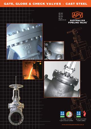
WEDGE & PARALLEL SLIDE GATE VALVES
EXPANDING & SLAB GATE VALVES
METAL SEATED BALL VALVES

OVERVIEW CATALOGUE
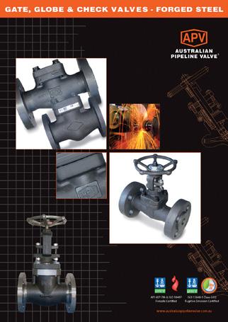
WEDGE & PARALLEL SLIDE GATE VALVES
EXPANDING & SLAB GATE VALVES
METAL SEATED BALL VALVES
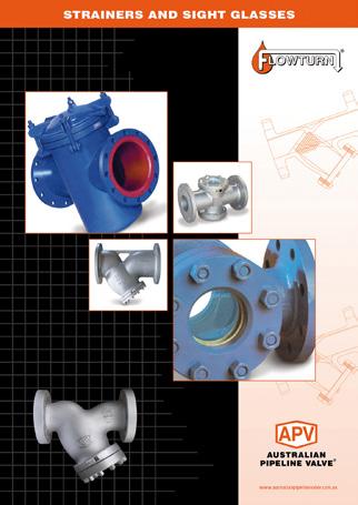
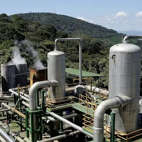
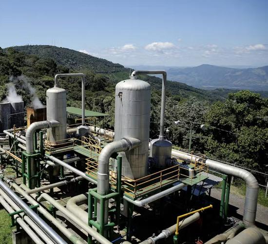
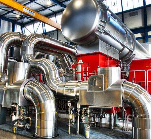
The controlled capture and processing of highheat, pressurised steam requires precision engineering and equipment.
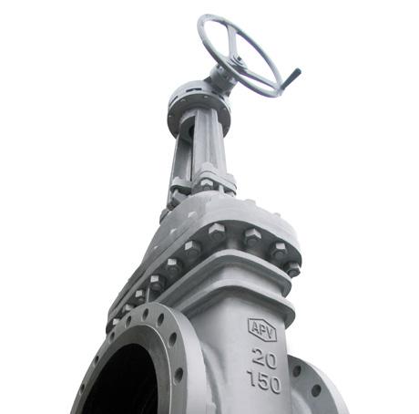
APV valves are available for all types of Geothermal plants which includes dry steam, flash steam and binary cycle. APV manufactures high-quality, high-performance geothermal valves. Geothermal power plants utilise heat in the form of steam, brine and/or heat transfer fluids to activate steam turbines to produce electricity.
APV manufactures a complete line of lowmaintenance, dependable Thru Conduit Expanding & Slab Gate valves, Parallel Slide & Wedge Gate valves as well as metal to metal seated Ball valves designed specifically for geothermal service. Made of materials that resist the impurities contained in the different geothermal processes.
Silica scaling can cause build-up, valve leakage and complete valve failure. Hence, APV valves are designed and proven to operate reliably in demanding geothermal service to 370ºC.
Trim Configuration Options:
Inconel stem/gate
316 SS stem/gate
17-4 PH stem/gate
Inconel lined bore & seal area
Stellite overlay ST #21/ ST #6

LIST
ANSI CLASS 150 ~ 2500
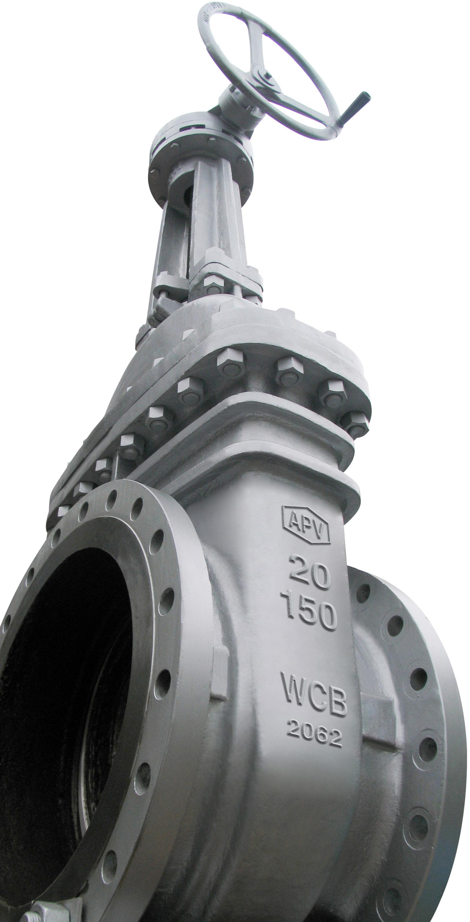
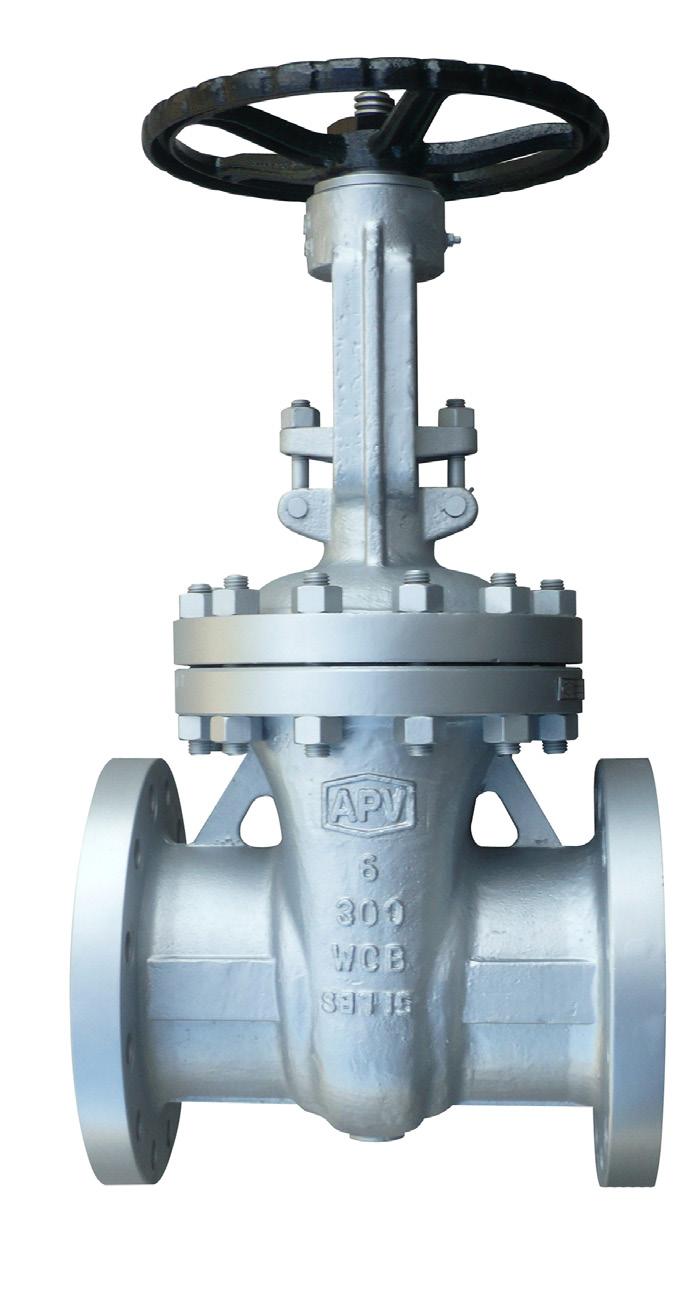
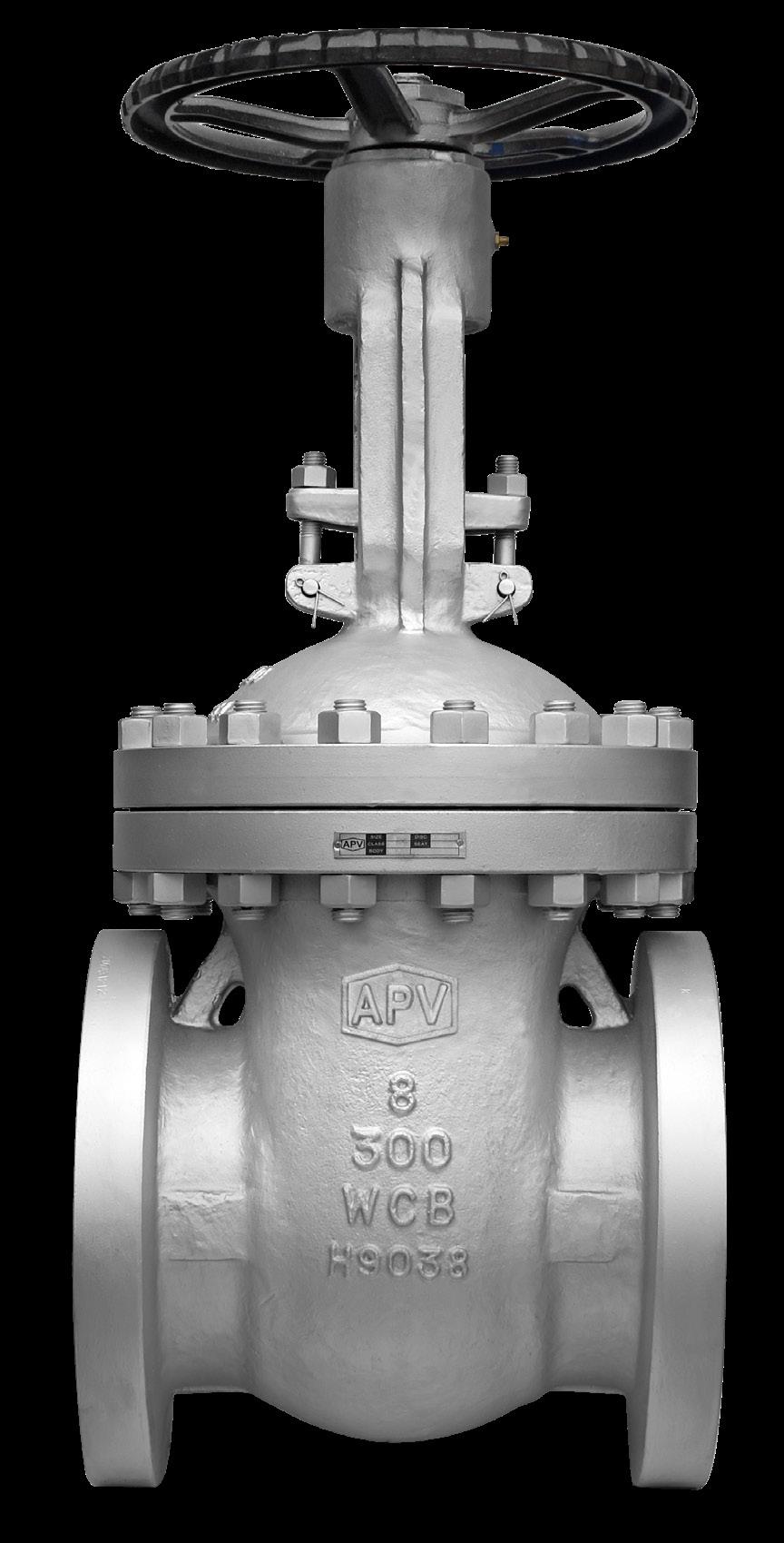
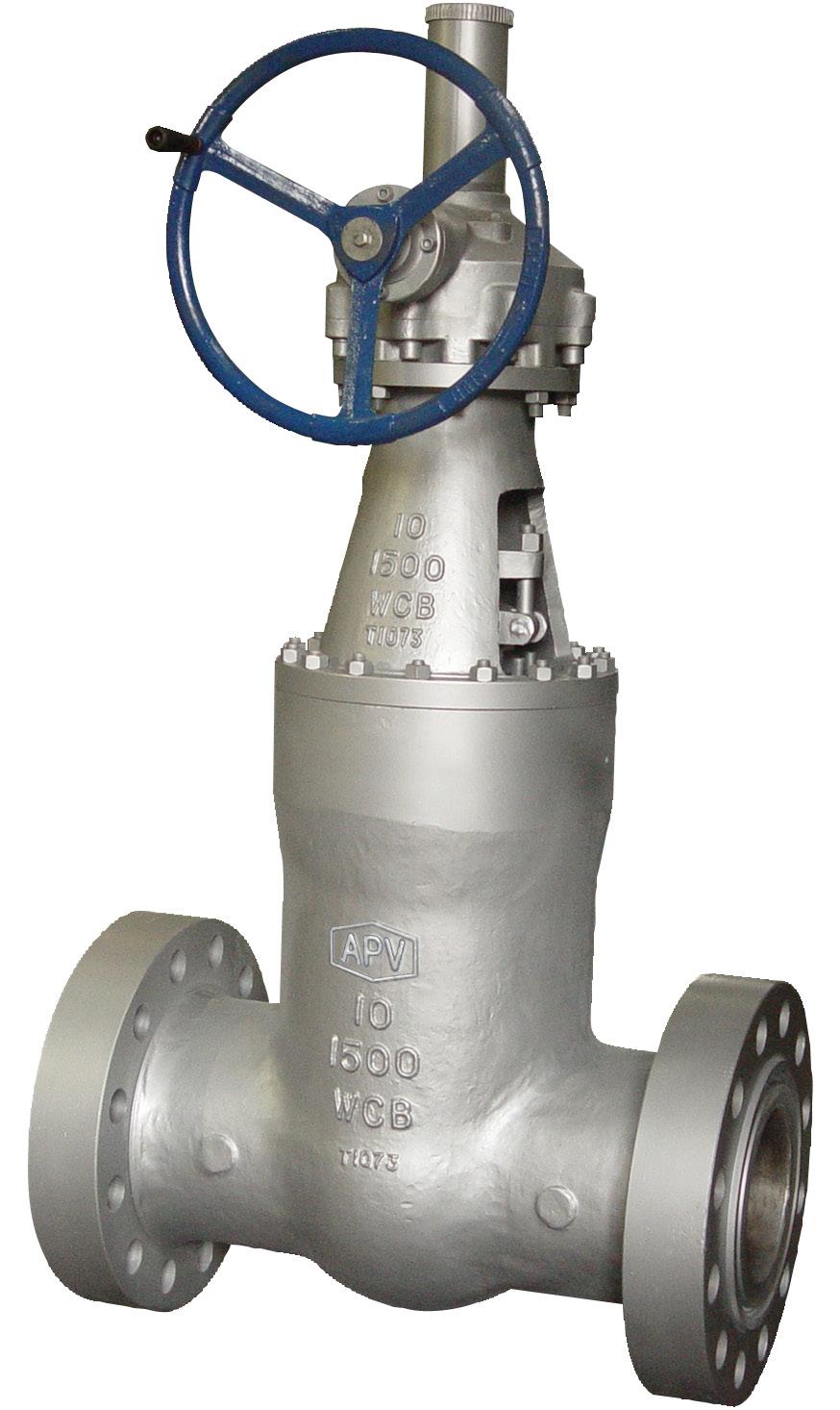
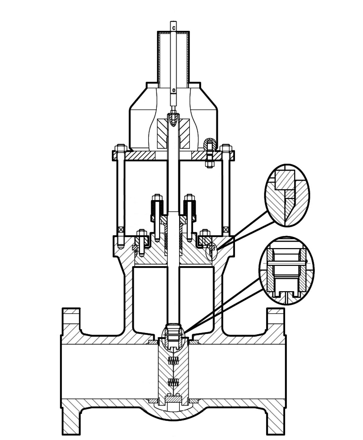
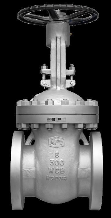
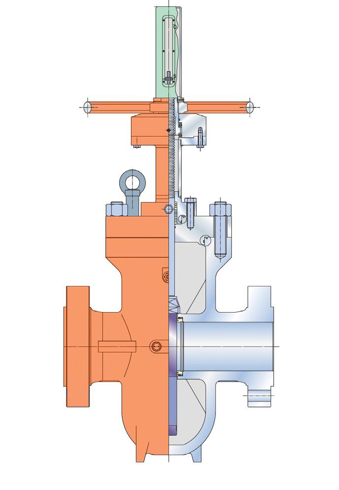
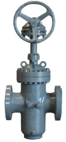
• Bolted bonnet, OS&Y, Flexible wedge.
• On smaller size valves, the yoke is cast integral with bonnet. Larger size valves have two piece yoke, refer to individual drawing.
• Stem nut is mounted with ball bearings to reduce operating torque for ease of manual operation in larger sizes and higher classes.
• Self aligning two piece gland.
• Valves designed to API Std. 600
• Valves tested to API Std. 598
• Face-to-face to ANSI B16.10
• Flanged ends to ANSI B16.5
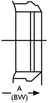
• Butt-welding ends to ANSI B16.25
• Trim and seating surface as per API 600 standard.
• Stuffing box smoothness ≤Ra 3.2 µm (superior • Stem smoothness to API 600 ≤Ra 0.80 µm


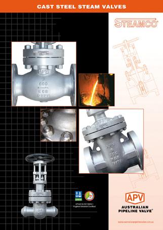
Cast steel valves are designed and manufactured to conform with API, ASTM, ANSI and other applicable internationally recognised standards, to possess all the qualities to meet with stringent requirement criteria of petroleum, petro-chemical and general industrial applications.
Valves are tested in accordance with applicable API standards. Full traceability is maintained.
Valves offer the option of hard facing on the wedge (disc) and seating areas.
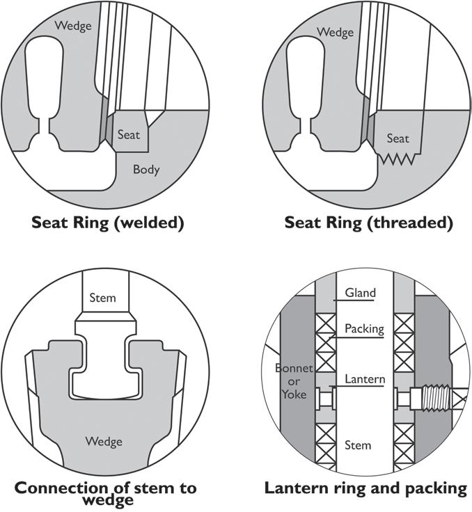
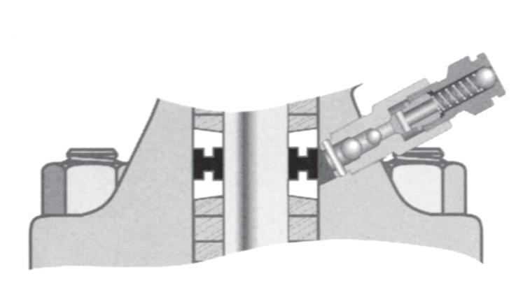
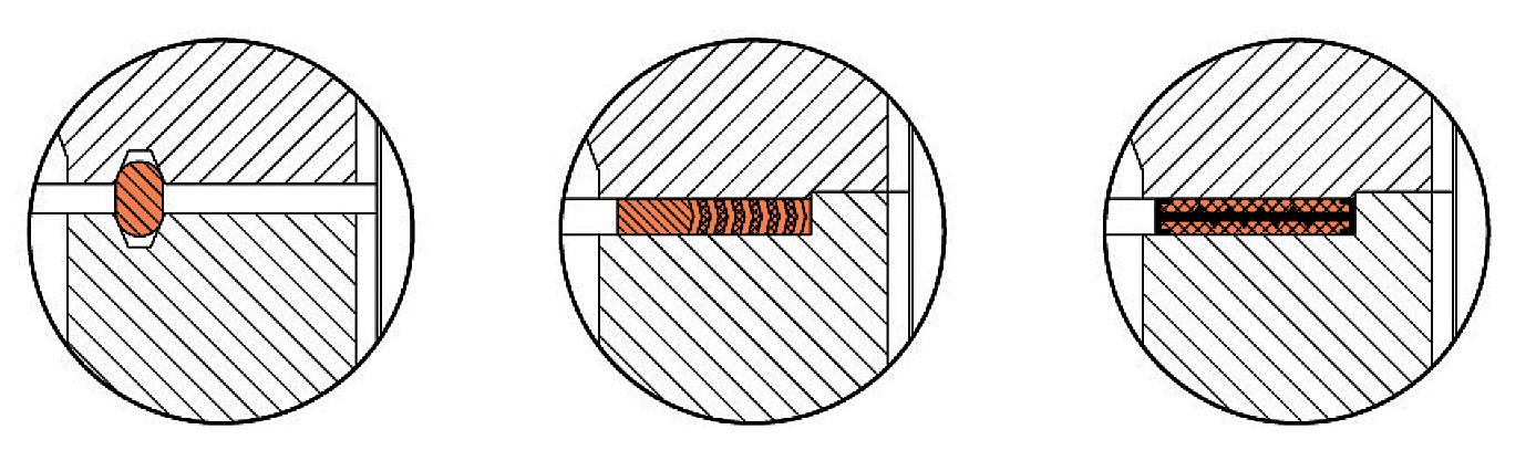
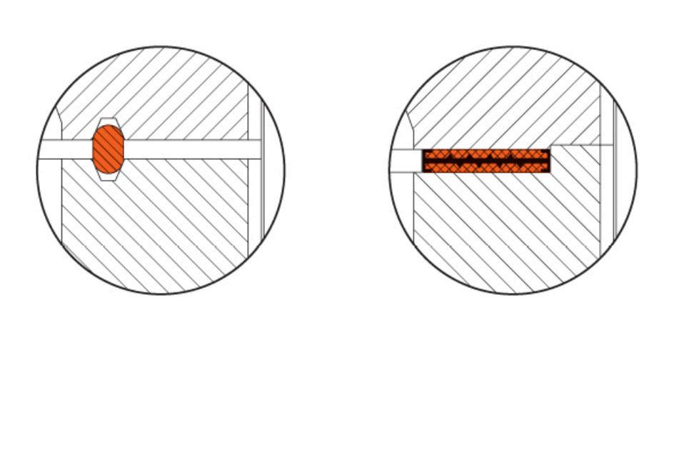
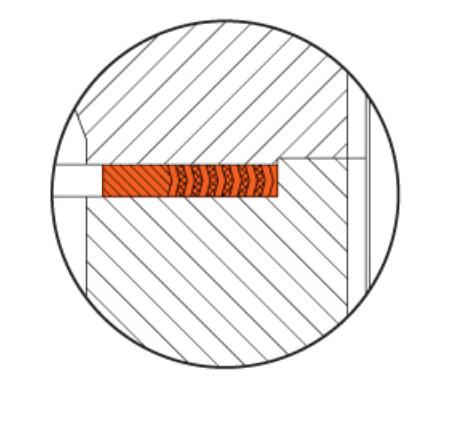
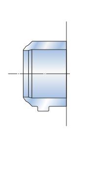
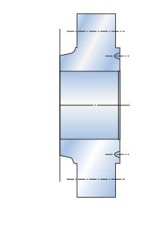
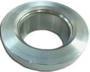
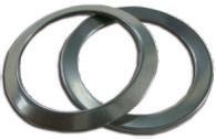
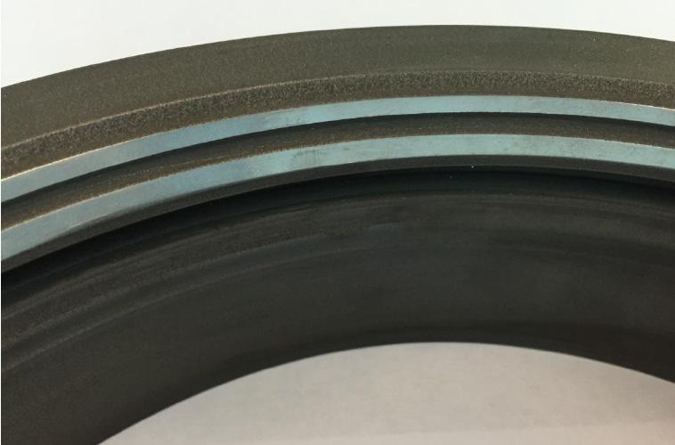
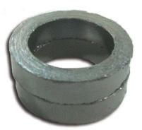
Gate Valves are optionally available with lantern rings. These rings along with double packing provide a leak-off connection. Alongside are illustrations of lantern rings as well as disc connection. Fugitive emission packing sets do normally need a lantern ring.
APV offers fugitive emission service valves on special request. The valves comply with environmental protection requirements. APV fugitive emission valves are designed, manufactured and tested to meet less than 100ppm with packing conforming to API 622 and valve design tested to API 624 and ISO 15848-1. Furthermore, optional live-loading of packing bolts is available. Two sets of belleville plate springs maintain a permanent packing stress of 24,000-28,000 kPa. Live-loading extends low emission service life especially in service with high pressure/temperature transients.
The stem on all APV fugitive emission service valves is surface finished to ≤Ra 0.80 µm. Straightness and roundness are precisely controlled. The stuffing box has a maximum ≤Ra 3.2 µm surface finish. Cylindricity and verticality are precisely controlled.
API 600 (Gate Valves)
Shell wall thickness and general valve design specifications
Pressure-temperature ratings
Face-to-face & End to end dimensions
API 603 (Gate Valves)
API 594 (Check Valves)
API 623 (Globe Valves)
ANSI B16.34
ANSI B16.10
Flanged end dimensions ANSI B16.5*
Welding end dimensions ANSI B16.25
*Valves 700NB (28”) and larger according to MSS SP-44 or API 605 are available.
Live Loading is an addition of spring washers to the gland studs to maintain the packing load of the valve over time.
The bellow seal replaces the dynamic sealing system of a stem packing by a static sealing system between the valve bonnet and the valve stem bottom. It prevents the valve from the risk of leakage from the valve packing for VOC or toxic services.
This catalogue is an overview only. For full sizes, dimensions & materials please refer to the APV Gate, Globe & Check catalogue. Click here As-built drawing can be supplied in accordance with specification requirements.
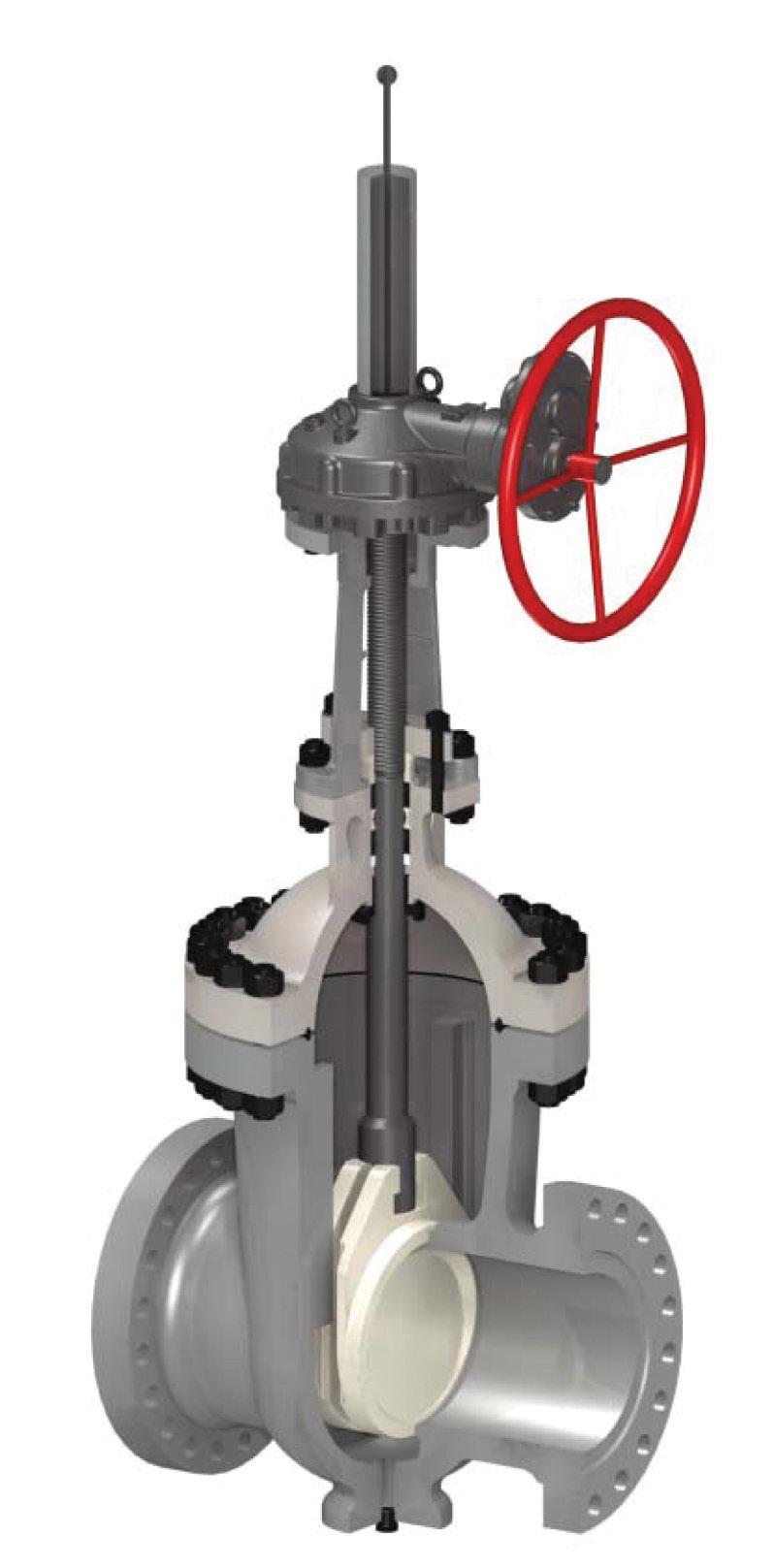
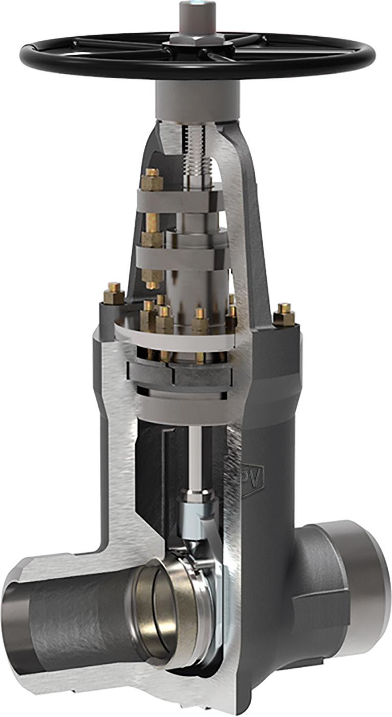
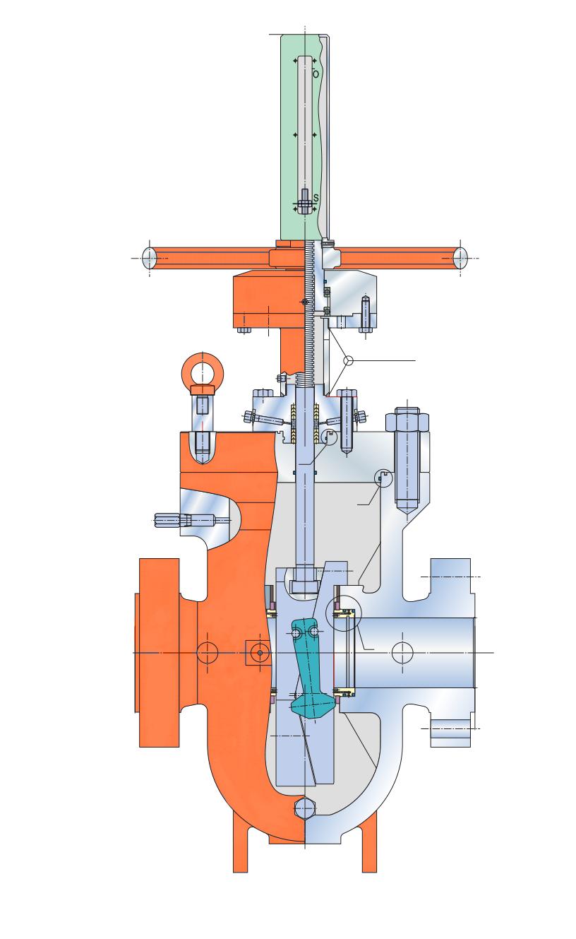
Full body wedge guides allow correct wedge alignment. Yoke sleeve with bearings reduce torque for easy operation. Seat rings allow easy access for maintenance and packing replacement is simple. Seat face 13Cr hardfaced, ground and lapped to a Ra 0.4~0.8 µm finish. Wedge is ground and lapped to a Ra 0.4~0.8 µm finish and tightly guided to prevent dragging and seat damage. Non-rotating stem with precision Acme threads and burnished finish. Rotating stem nut is austenitic ductile iron Gr. D-2C renewable.
API 600 and ANSI B16.34. Dimensions to ANSI B16.10 and ISO 5727. Stuffing box smoothness ≤Ra 3.2 µm superior to API 600. Stem smoothness ≤Ra 0.80 µm as per API 600.
All gate valves are available with optional PTFE seat rings. The moulded PTFE ring is bonded into a seat ring groove in the face for maximum service life. This design is excellent for lower temperature service where tight shutoff is required.
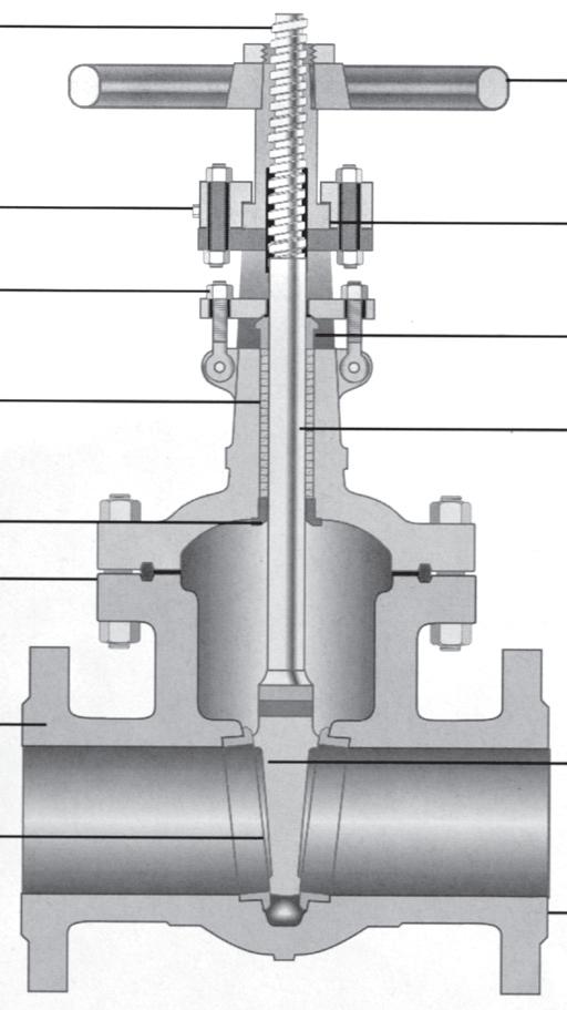
Grease Fitting - to minimise wear and operating torque
Parallel slide style also available, see page 20, 84 - 88 and also see APV Steamco Catalogue
Yoke Sleeve - furnished in ductile Ni-resist or aluminium-bronze for low torque operation
5. Swing Bolt - easier maintenance and packing replacement
6. Gland - flange is self-aligning to eliminate stem damage
7. Stuffing Box
8. Stem - upset forge T-head stems to eliminate possibility of a bent stem jamming the valve
9. Backseat - provides back-up stem seal
10. Bonnet Joint
11. Body - full ported, heavy wall body API 600 wall thickness 12. Wedge - heavy pattern. Available in solid & flex wedge
Description Material Specs. Body
A216 Gr. WCB Bonnet
Carbon
+
A216 Gr. WCB
A216 Gr. WCB + Stellite #6
Stem Stainless Steel 17-4PH
Hand Wheel Ductile
Seat Carbon
+ HF A105 + Stellite #6
Back Seat Ring Integral Stellite #6
Yoke Sleeve Ductile Iron or Bronze A439 Gr. D2C or B62
Sleeve Gland Carbon Steel A216 Gr. WCB
Gland Flange Carbon Steel A105
Gland Ring Stainless Steel A276 Gr. 420 Wheel Nut Carbon Steel A105
Bonnet Bolt Alloy Steel A193 Gr. B7/B7M
Bonnet Nut Alloy Steel A194 Gr. 2H/2HM
Gland Bolt Alloy Steel A193 Gr. B7
Gland Nut Alloy Steel A194 Gr. 2H
Gland Bolt Pin Alloy Steel A108 Gr. 1020
Bearing - Thrust Ball
Grease Nipple Carbon Steel A307 Gr. B
Set Screw Carbon Steel A307 Gr. B
Name Plate Stainless Steel 304/AL
Packing Asbestos Free Reinf. Graphite/Chesterton 1724*
Gasket Spiral Wound 316 Graphite filled *260°C Max.
DIMENSIONS (MM) DIMENSIONS (MM)
Description Material Specs.
Body Carbon Steel A216 Gr. WCB
Bonnet Carbon Steel A216 Gr. WCB
Disc Carbon Steel + HF A216 Gr.WCB + Stellite #6
Stem Stainless Steel 17-4PH
Hand Wheel Ductile Iron A536 Gr. 65-45-12 Seat
Sleeve Gland
Gland Flange
Gland
Bonnet Bolt Alloy Steel A193 Gr. B7/B7M
Bonnet Nut Alloy Steel A194 Gr. 2H/2HM
Gland Bolt Alloy Steel A193 Gr. B7
Gland Nut Alloy Steel A194 Gr. 2H
Gland Bolt Pin Alloy Steel A108 Gr. 1020
Bearing - Thrust Ball
Grease Nipple Carbon Steel A307 Gr. B
Set Screw Carbon Steel A307 Gr. B
Name Plate Stainless Steel 304/AL
Packing Asbestos Free Reinforced Graphite
Gasket Spiral Wound 316 Graphite filled
DIMENSIONS (MM)
Yoke
Gland
Gland
Gland
DIMENSIONS (MM)
DIMENSIONS (MM)
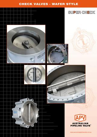
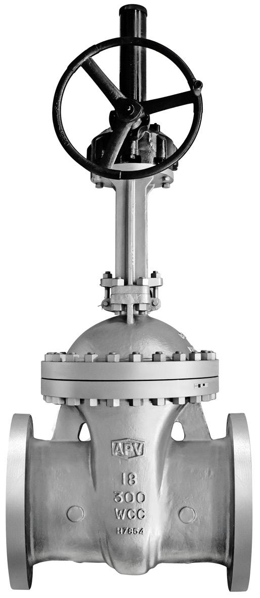
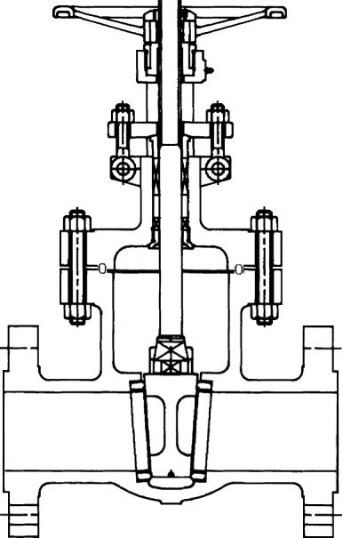
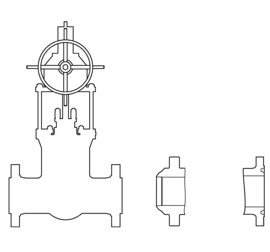
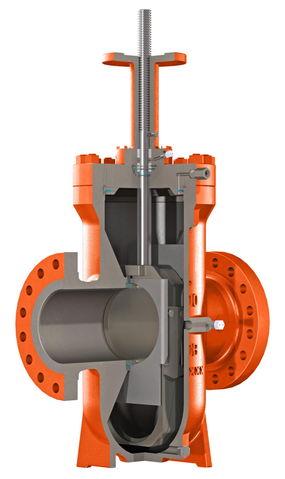
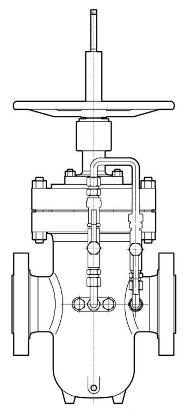
Normally utilised for shut off service but are not recommended for throttling. Gate valves are normally installed in horizontal pipe runs with the valve stem vertically up. They can be installed in horizontal or vertical pipe runs. After closing with sufficient force, the stem should be backed off slightly (1/8 turn) to relieve stem load. Parallel Slide Valves have self aligning discs with no wedging force and react freely to thermal changes. The design also ensures uniform seat wear and ease of maintenance. Parallel Slide Gate Valves are ideal where high differential pressure or thermal expansion may cause sticking of wedge to gate in traditional gate valves. 1. Yoke Sleeve - aluminium-bronze yoke sleeve with thrust bearings for ease of opening
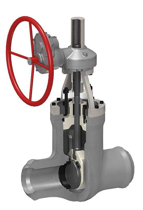
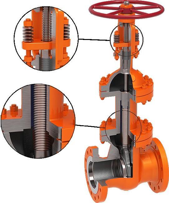
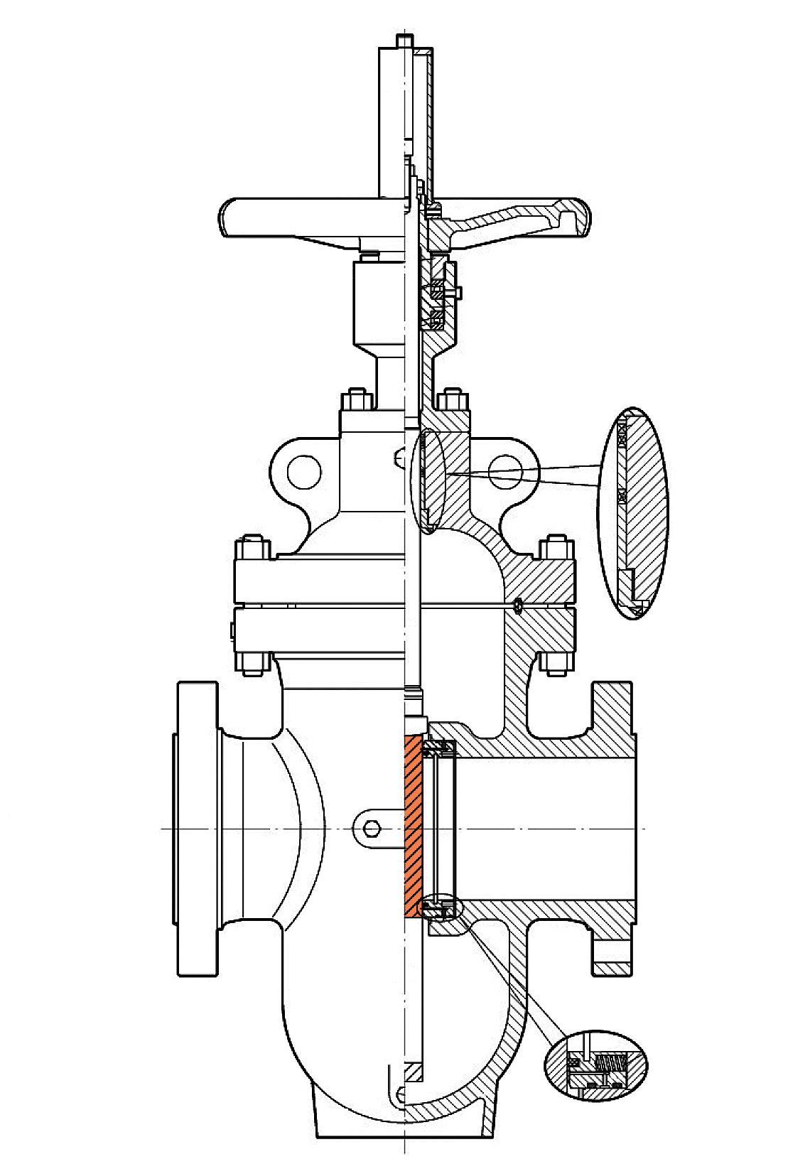
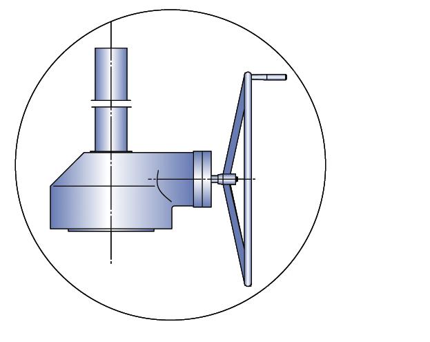
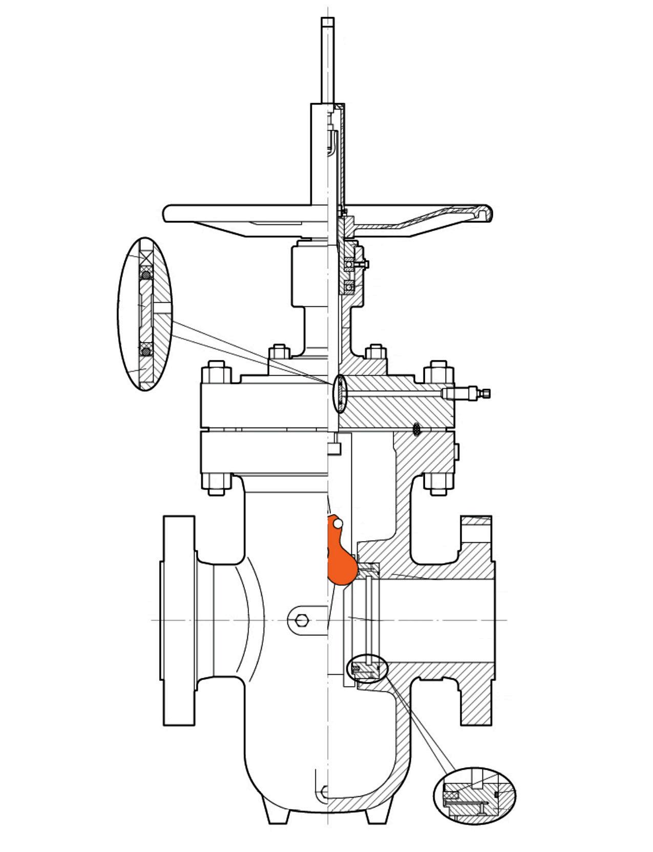
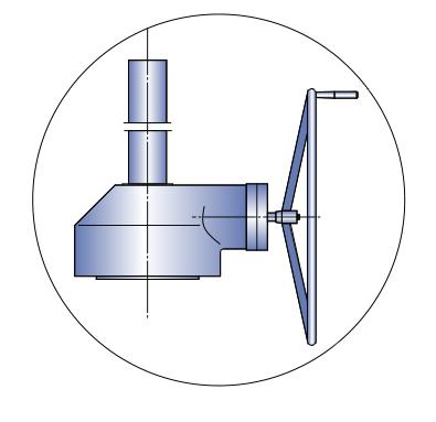
The torque arm design guides and centralises the stem and prevents stem movement which reduces wear on packing rings & enables better sealing as well as reducing torque. Only the stem nut rotates. The arm also provides visual stem position indication & can be interfaced with position switches. Optional live loaded packing system is shown.
Back Seat - Integral, hardfaced
Pressure Seal - retaining ring and mild steel silver plated/SS/SS+GRP gasket to aid disassembly and provide maximum seal 8. Seat Ring - hardfaced seat rings are welded to body and are designed for ease of maintenance
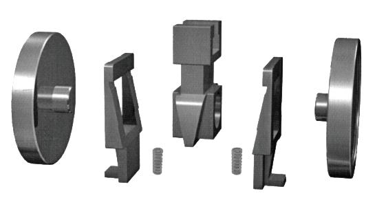
Discs - Spring loaded discs are self-aligning and reduce actuator torque requirements
CAT 50~600AP25SXXXX-M/N~50~600AP76SXXXX-M/N 600~2500 CLASS
FEATURES
Pressure seal bonnet
Complete flow isolation in either direction
Minimum pressure drop
Inherent self cleaning action
Freedom from leakage, resistant to temperature or pressure changes
In line maintenance
By pass available upon request
SPECIFICATIONS
&
15848-1 Fugitive Emission Certified
Basic Design API 600, ASME B16.34 & MSS SP-144
Face to Face ASME B16.10
End Flange ASME B16.5
B.W End ASME B16.25
Test and Inspection API 598
607-7th & ISO 10497 Firesafe Certified
AP87S-P / AP25S-P MM, INCH & KG
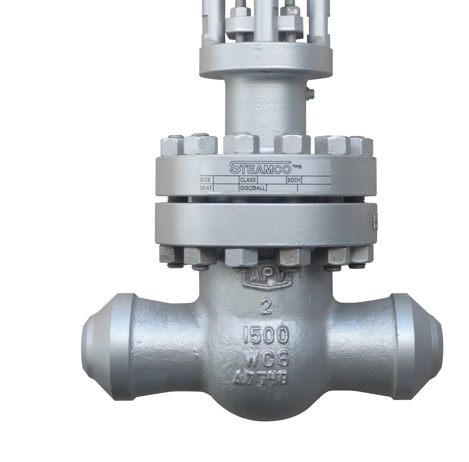
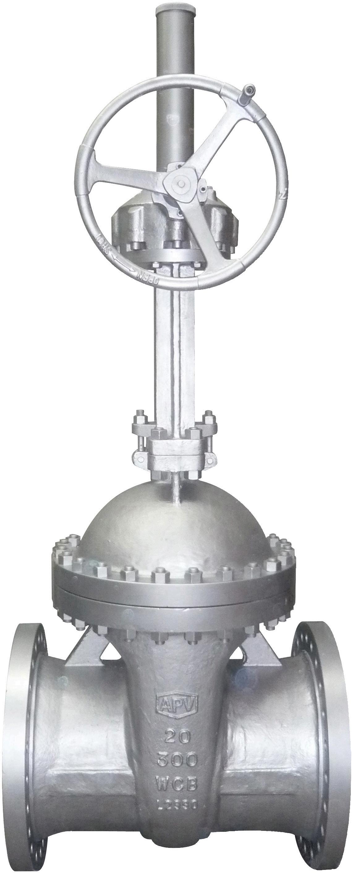
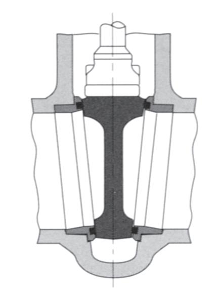
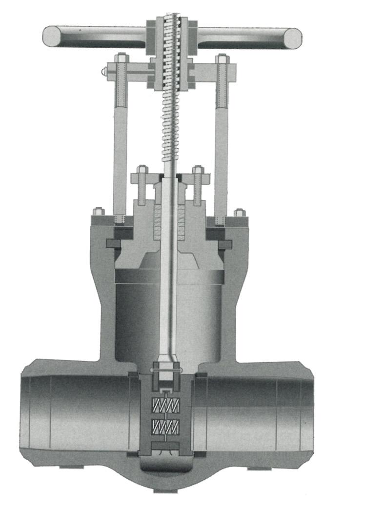
For installation in applications such as industrial, mining and mechanical services. Suitable for super-heated steam, H.T.H.W steam condensate and water. This design consists of two discs, kept in contact with parallel body seats, using the line pressure and seating action to effect tight closure.
Temperature changes in the line are accommodated by the expanding disc and do not affect the action of the valve. When being opened or closed, the discs slide across the seat faces, dislodging any foreign matter. The valve operating stem is outside screw rising through the handwheel.
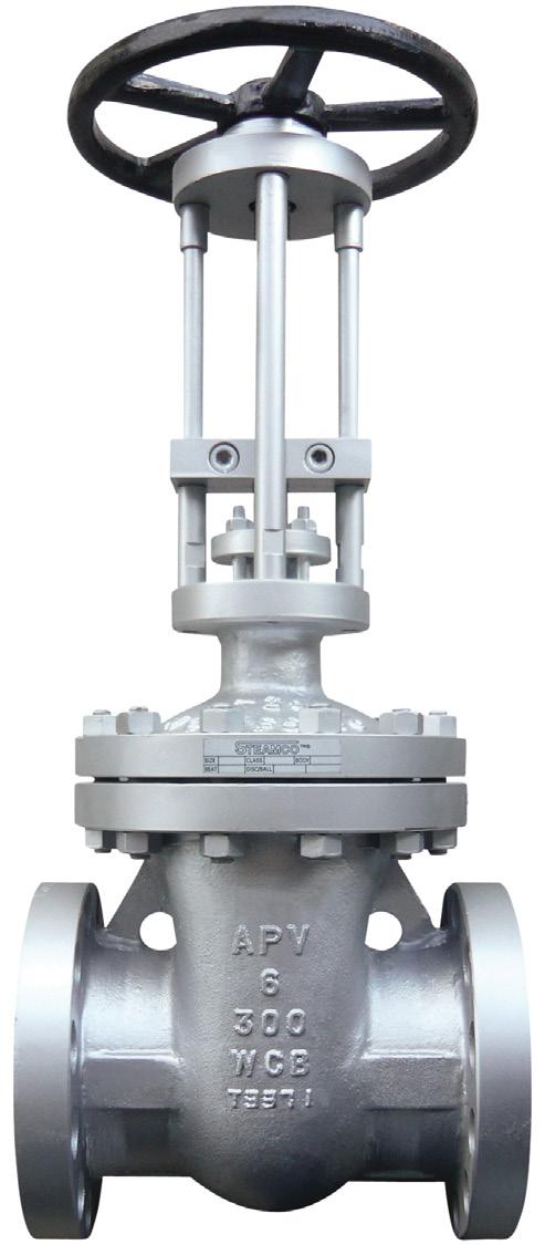
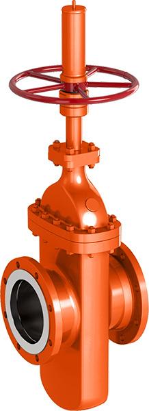
These valves are suitable for full bore steam use, where a low pressure drop across the valve is required. Also suitable for water, oil, gas, etc. PARALLEL SLIDE GATE VALVE - BOLTED BONNET
For superheated steam etc. consult chart. WC6 chrome-moly available body for high temperature applications. STANDARD MATERIAL SPECIFICATIONS Part Material
SPECIFICATIONS
Basic Design API 600, ANSI B16.34
Face to Face Dimension ANSI B16.10
End to End Dimension ANSI B16.10
Flanged Ends - ANSI 16.5
B.W. Ends ANSI B16.25
Drilling to ANSI or BS/AS 2129 Table D to H or AS 4087 / AS 4331 / ISO 7005-1 PN 10 to 250
Pressure/Temperature ratings to ANSI B16.5
Body
Seat Ring A105+STL 6#
Disc* A105+410
Spring* Inconel X-750
Washer 304 SS
Screw B8
Stem ASTM A182 F6A/17-4PH
Gasket 304 S.W. +Graphite
Bonnet ASTM A216 Gr. WCB
Back Seat Ring ASTM A182 Gr. F6
Packing Braided Graphite
Gland AISI 410
Gland Flange ASTM A216 Gr. WCB
Eyebolt ASTM A193 Gr. B7
Grease Nipple 304 SS
Stem Nut ASTM A439 Gr. D2
Handwheel A536
Screw 1035
Nameplate 304 SS 29 Rivet 304 SS
* Also available with expanding wedge energiser (no spring) style - refer to drawing.
O.S. & Y. Rising Stem Full Port, Expanded Parallel Slide Gate Valve, Double Disc, Pressure Seal or Bolted Bonnet, Welded-in or Threaded Seat Rings. Mechanically loaded seating for low and high pressure sealing.
Parallel slide dual loaded discs ensure superior shut off and allow by-pass/bleed fitment (double block and bleed requires soft seat inserts).
Pressure/temperature charts available on request.
Buttweld ends
PRESSURE/TEMPERATURE
For superheated steam etc. consult chart. WC6 chrome-moly available body for high temperature applications.
Suitable for super-heated steam, H.T.H.W steam condensate and water.
Temperature changes in the line are accommodated by the expanding disc and do not affect the action of the valve. When being opened or closed, the discs slide across the seat faces, dislodging any foreign matter.
These valves are suitable for full bore steam use, where a low pressure drop across the valve is required. Also suitable for water, oil, gas, etc.
O.S. & Y. Rising Stem Full Port, Expanded Parallel Slide Gate Valve, Double Disc, Pressure Seal or Bolted Bonnet, Welded-in or Threaded Seat Rings. Mechanically loaded seating for low and high pressure sealing.
Parallel slide dual loaded discs ensure superior shut off and allow by-pass/bleed fitment (double block and bleed requires soft seat inserts).
Pressure/temperature charts available on request.
Part Material
1 Body ASTM A217 WCB
2 Seat Ring ASTM A105+STL.6
3 Wedge Blocks ASTM A743 CA40
4 Discs ASTM A105+STL.12
5 Springs Inconel X-750
6 Disc Yoke ASTM A743 C40
7 Guides C.S.
8 Stem ASTM A182 F6A/17-4PH
9 Studs ASTM A193 B7
10 Nuts ASTM A194 2H
11 Gasket 304SS+GRAPHITE
12 Bonnet ASTM A216 WCB
13 Back Seat ASTM A276 410
14 Packing FLEXIBLE GRAPHITE
15 Packing 316+BRAIDED GRAPHITE
16 Gland ASTM A276 410
17 Gland Flange ASTM A217 WCB
18 Pins AISI 1035
19 Eyebolts ASTM A193 B7
20 Nuts ASTM A194 2H
21 Stem Nut ALUMINIUM BRONZE
22 Retaining Nut AISI 1035
23 Handwheel MALLEABLE IRON
24 Nuts AISI 1035
25 Nameplate 316SS
26 Rivets 316SS
27 Bearings SUB-ASSEMBLY
28 Yoke ASTM A216 WCB
29 Studs ASTM A193 B7
30 Nuts ASTM A194 2H
31 Grease Nipple BRASS
* Also available with expanding wedge energiser (no spring) style - refer to drawing.
SPECIFICATIONS
Basic Design API 600, ANSI B16.34
Face to Face Dimension ANSI B16.10
End to End Dimension ANSI B16.10
Flanged Ends ANSI 16.5
B.W. Ends ANSI B16.25
Drilling to ANSI or BS/AS 2129 Table D to H or AS 4087 / AS 4331.1 / ISO 7005-1 PN 10 to 250
Pressure/Temperature ratings to ANSI B16.5
Note: 15mm to 40mm NB 150 ~ 2500 Class also available refer to individual drawings.
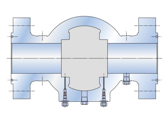
Double block and bleed (DBB)
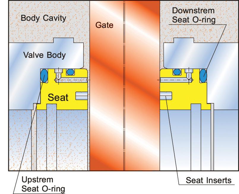
Double sealing established by initial plastic-to-metal contact in addition to metal-to-metal contact, both upstream, downstream. In the closed position, both upstream and downstream pressures energize the seats to form a tight seal on both seats simultaneously. This allows the body cavity to be manually bled.
Pressure energised seats
As the upstream pressure increases, the upstream seat is pushed against the slab gate (piston effect), and subsequently the slab gate pushes against the downstream seat, creating a tight seal between both seats and the slab gate. In the absence of line pressure, the energized O-rings behind the seats provide the seating force on the slab gate to maintain a tight effective seal.
A soft seat insert in each seat is protected by the metal sealing surfaces in full contact with the gate, in both open and closed positions, completely isolated from the flow stream, greatly extending the seat life.
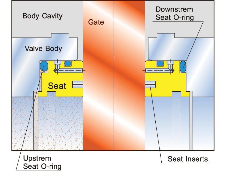
Cavity over pressure self-relieving
When the medium trapped in the body cavity expands as a result of the thermal expansion, the pressure buildup will push the upstream seat back into its recess and relieves to the upstream through the gap between the seat and the slab gate.
Protection of seat faces
Seat faces are not exposed to the flow stream and in full contact with the gate, in both open and close position, greatly extending seat life.
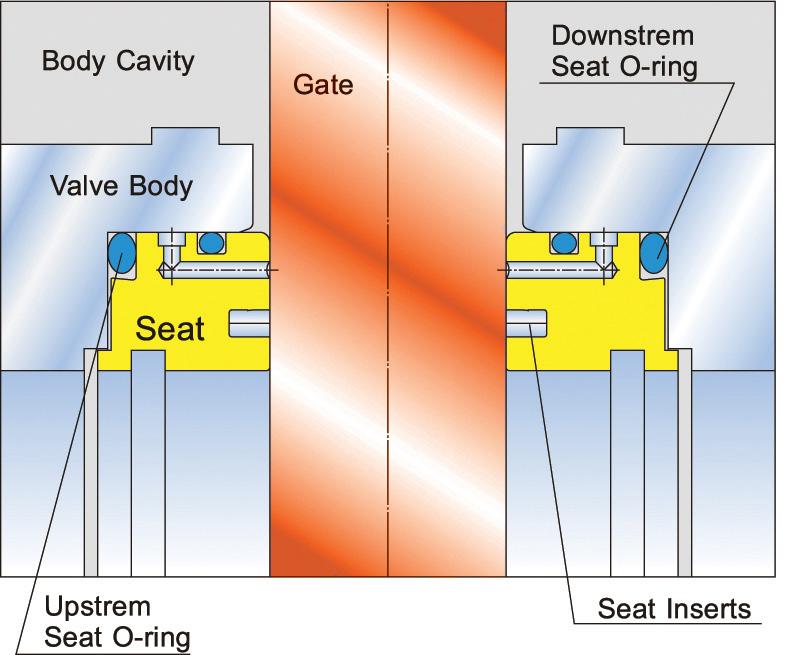
When the valve in the closed position with equal pressure in the valve, the energized seat O-Ring on both seats will push the seat rings against the gate to provide an initial soft-to-metal sealing.
When the line pressure is applied to the valve, the gate will be pushed against the downstream seat until the gate compresses the soft seat insert and forms soft-to-metal and metal-to-metal double seal. The downstream O-ring provides the seal between the downstream seat and body. The force of line pressure acting on the upstream seat against the gate provides a soft-to-metal seal, and the upstream seat O-ring provides the seal between the upstream seat and body.
When the valve cavity pressure exceeds line pressure due to thermal expansion, the upstream seat is forced back into its recess and the excess pressure in the body cavity is relieved between the seat and the gate into the line.

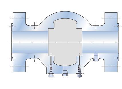
Saf-T-Seal®* style
Through conduit design with minimum flow resistance
Double sealing replaceable seat
Locking device
Backseated Stem
Body thermal relief system upon request
Stem extension upon request
Double block and bleed upon request
Soft seat or ‘Metal to Metal’
SPECIFICATIONS
Basic Design API 6D ASME B16.34
Face to Face API 6D
End Flange 2”-24” ASME B16.5
26”- 40” ASME B16.47
B.W End ASME B16.25
Test and Inspection API 6D & API 598
Manufacturing to NACE MR0175 on request
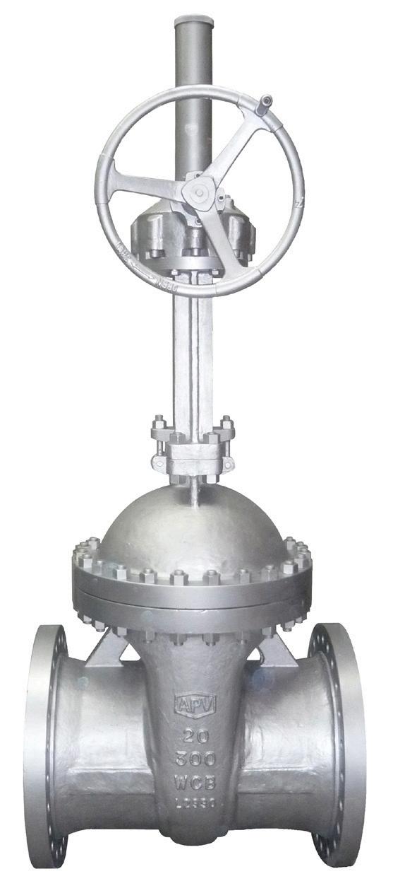
20” 300LB
16” 600LB ≥ 12” 900LB ≥ 10” 1500LB ≥ 8” 2500LB ≥ 4”

Double isolation and bleed DIB-1 (both seats bi-directional)
Double sealing established on each seat bi-directionally by initial plastic-to metal contact in addition to metal-to-metal contact, both upstream, downstream and body cavity. In the closed position, the gate forms a tight seal simultaneously on both seats bi-directionally. This allows the body cavity to be manually bled. An automatic cavity pressure relief device is provided to relieve the build-up of over pressure in the body cavity.
Mechanically induced bubble tight seal
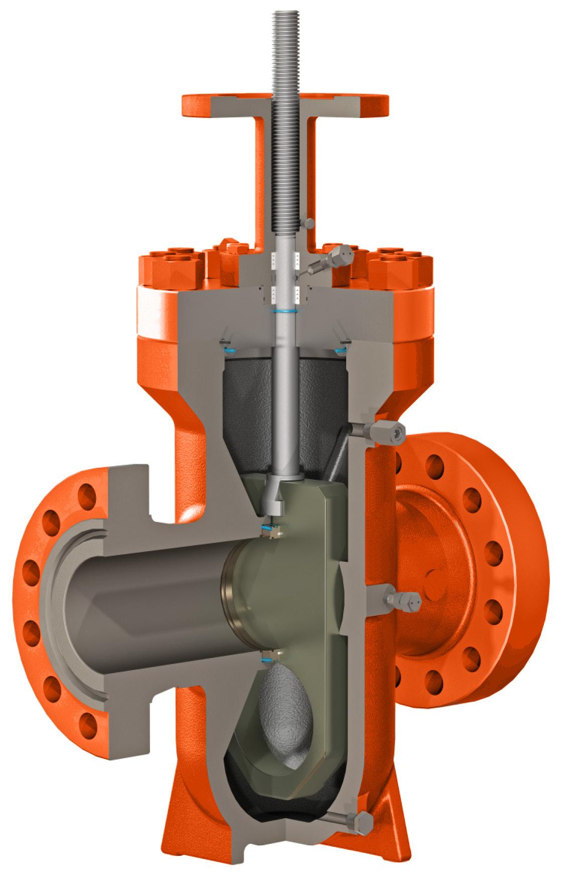
When closing, the segment is positioned by a mechanical stop while the gate continues going downward, expanding the segment and gate against their opposite seats. This action forms a bubble tight seal on both the upstream and downstream seat to reach a double isolation sealing function.
Wear and tear reduction
When the valve is completely closed, the gate and segment are wedged tightly against each seat. During operation, the gate and segment retract from the seats prior to stroking; this retraction provides an operating clearance to reduce rubbing of the resilient seat material and protects the sealing surfaces. Additionally this reduces the operating torque and allows a smaller and more economical operator for smooth operation.
In the fully closed position, the segment is positioned by the mechanical stop and the gate is wedged downward under stem thrust force, expanding the segment and gate to form a tight seal on each seat bi-directionally between upstream and downstream.
During travel between fully open or close position, the gate and segment retract from the seats prior to travel; this retraction provides an operating clearance to reduce wear on the sealing surface and operating torque.
The lever arm maintains the gate & segment surfaces parallel by guide plates, while the expanding gate assembly is moving through its stroke. Near the end of stroke, the guide plate allows the lever arm to tilt. The gate and segment slide against their angled faces under stem provided thrust force, creating the expanding seal action. In their final position, the gate and segment are mechanically secured in place. The guide plates forms a rail at both sides of the expanding gate assembly to guide its movements and align it with the seats.
When the bore of the segment is aligned with the body bore, the segment is positioned by the mechanical stop and the gate continues to move upwards, expanding the gate and the segment to form a through conduit bore and protect the sealing surface from flow erosion.
Pow-R-Seal®* Style
Through conduit design with minimum flow resistance
Double-sealing replaceable seat
Locking device
Body thermal relief system
Stem extension upon request
Soft Seat or ‘Metal to Metal’
SPECIFICATIONS
Basic Design API 6D ASME B16.34
Face to Face API 6D
End Flange 2”-24” ASME B16.5
B.W. End ASME B16.25
Test and Inspection API 6D & API 598 Manufacturing to NACE MR0175 on request
900LB
1500LB
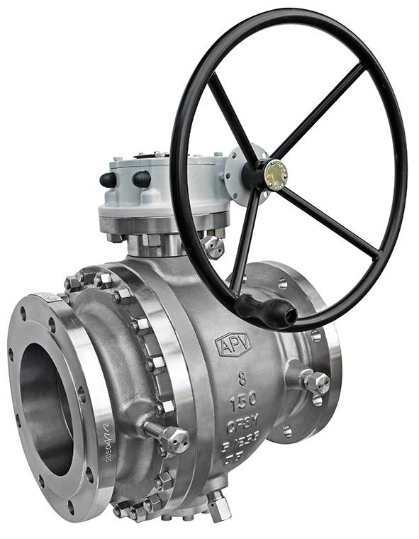
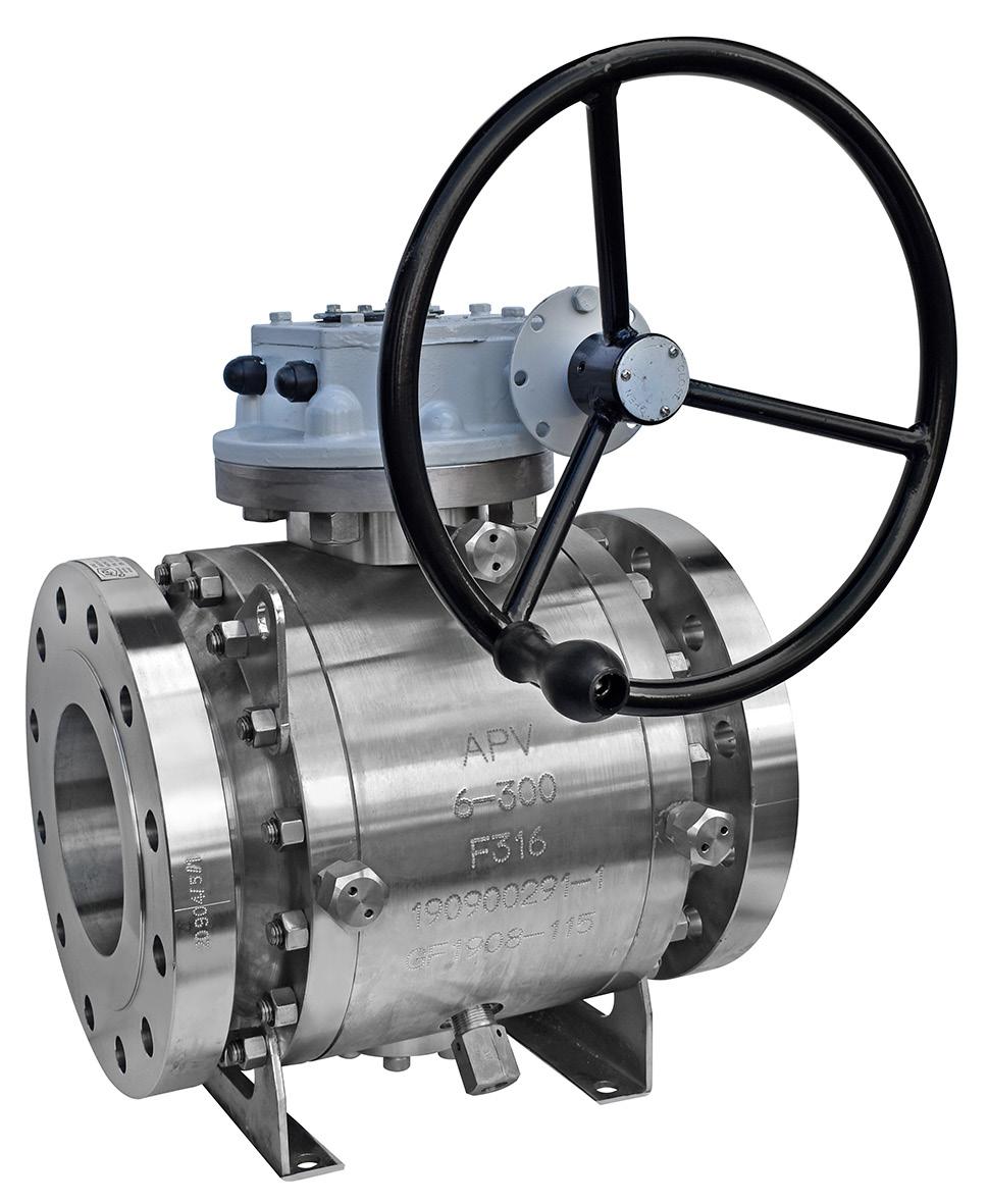
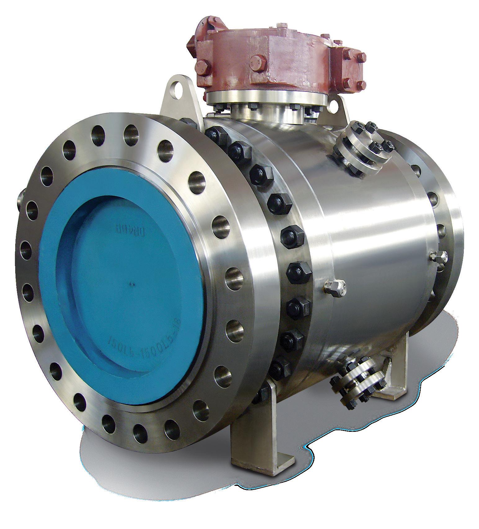
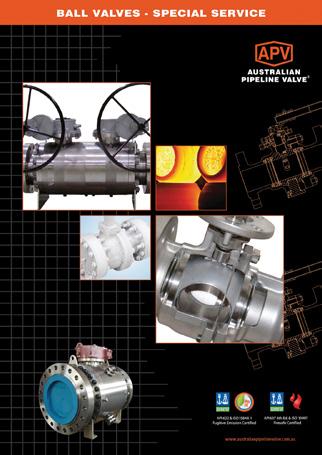
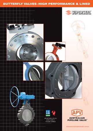
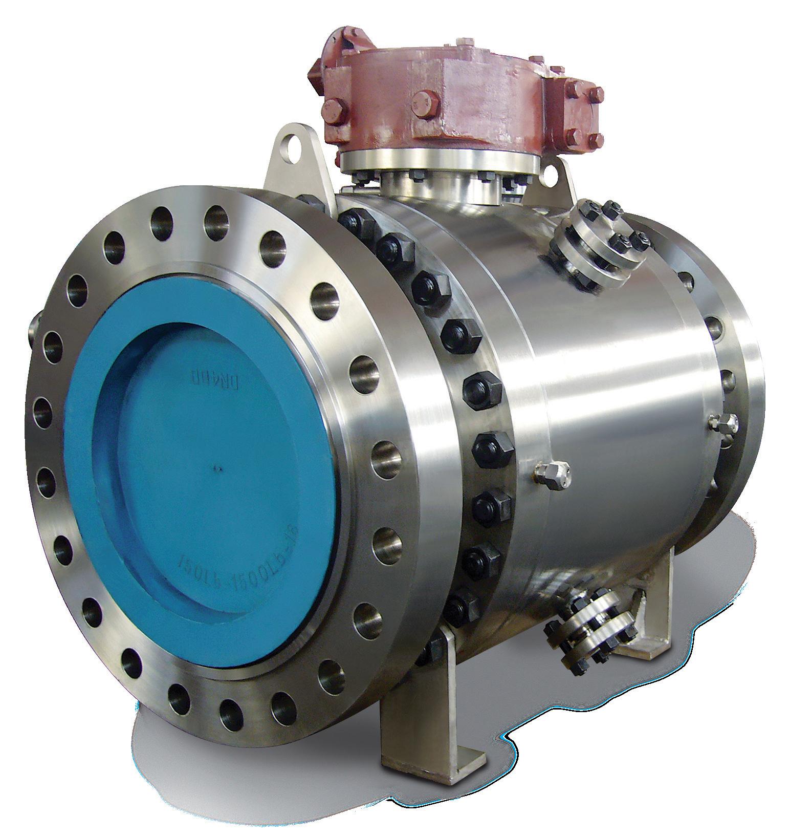
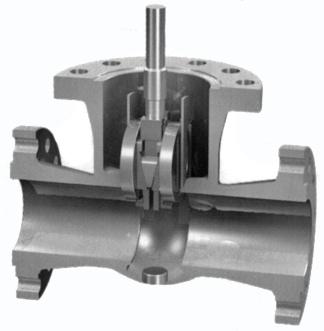
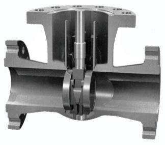
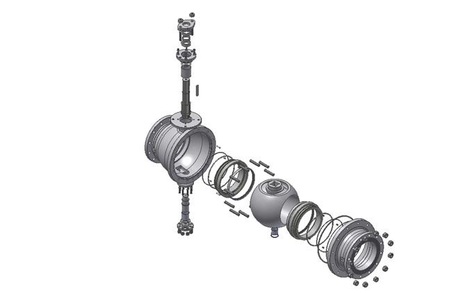
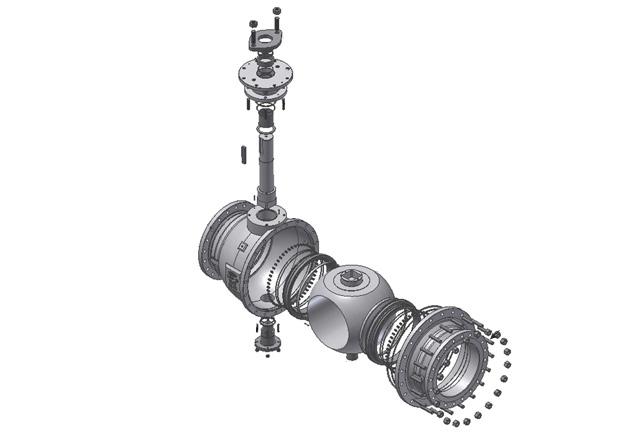
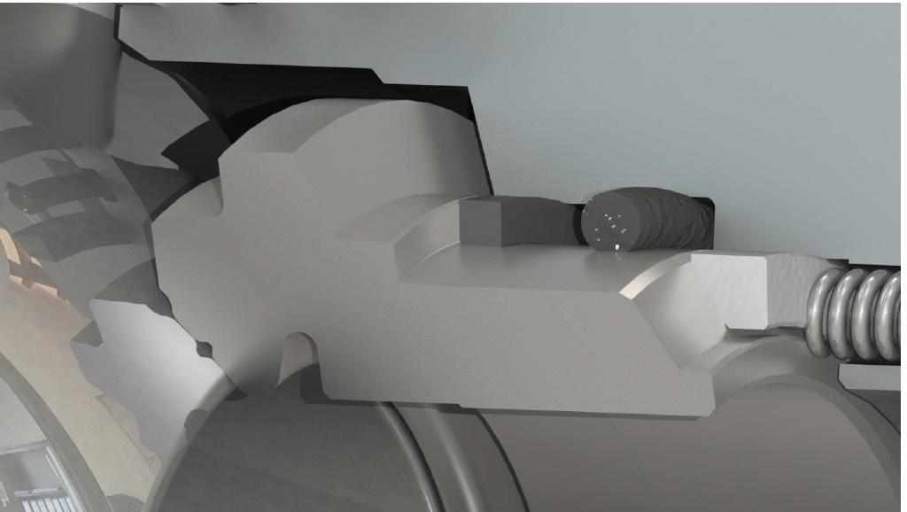
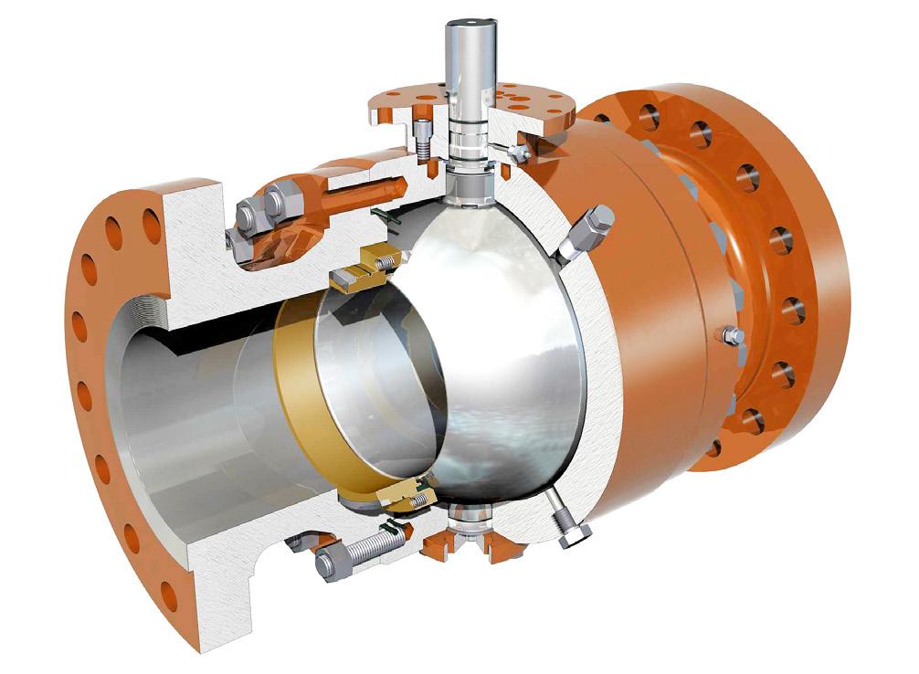
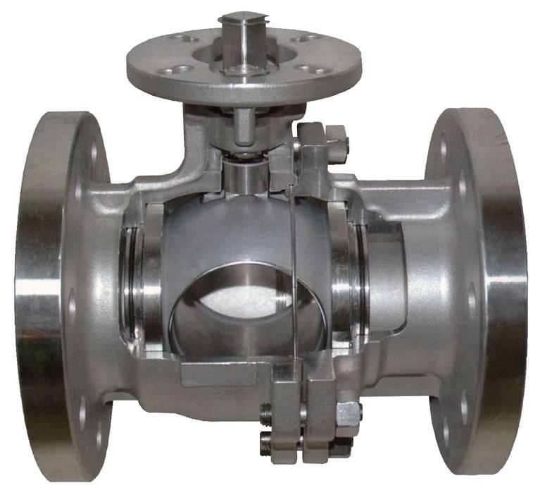
Australian Pipeline Valve manufacture severe and critical service ball valves. Valves can be manufactured in class IV, V and VI shut off as well as API 598 and MSS-SP61. Special resilient and metal seated high performance ball valves with ‘cam action seats’ are also available. This seat design lifts off the ball/disc during opening and closing to avoid seat damage. The design also protects the seat from high velocity and abrasion damage during initial opening. Trunnion Mounted Ball Valves designed for abrasive service, feature a metal to metal sealing between the ball and seat rings, while the sealing between the seat and the seat housing shoulders is achieved by means of o-rings, graphite gaskets or lip seal o-rings or bellows seals depending on service conditions.
The ball and the seat rings are hard-faced using different coating mediums such as Electro-less Nickel, Chrome Carbide, Tungsten Carbide, Chromium Carbide and Stellite depending on media, temperature & service to be handled. A specially designed seat ring avoids the inclusion of sand or other debris in the spring recess.
Special flushing systems for the seat pocket area are available on request for valves to be used in extremely “dirty” services. Valves can be bi-directional or uni-directional
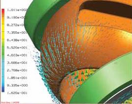
Proprietary mate-lapping is available which produces the tightest, most reliable seal available. All metal seated ball valves rely on continuous, unbroken contact between the ball and metal seat to create an isolating seal. 360° mate-lapping of the entire ball and seat produces optimal roundness, producing 100% ball to seat contact, regardless of the positioning. Traditional cup-lapping methods mate only the sealing band of the ball to seat surfaces creating ridges that distort the balls roundness and compromise the coating thickness. The sealing “sweet spot” is much smaller and a leak path may develop if even slightly misaligned resulting in reduced valve life, more maintenance and higher actuation costs.
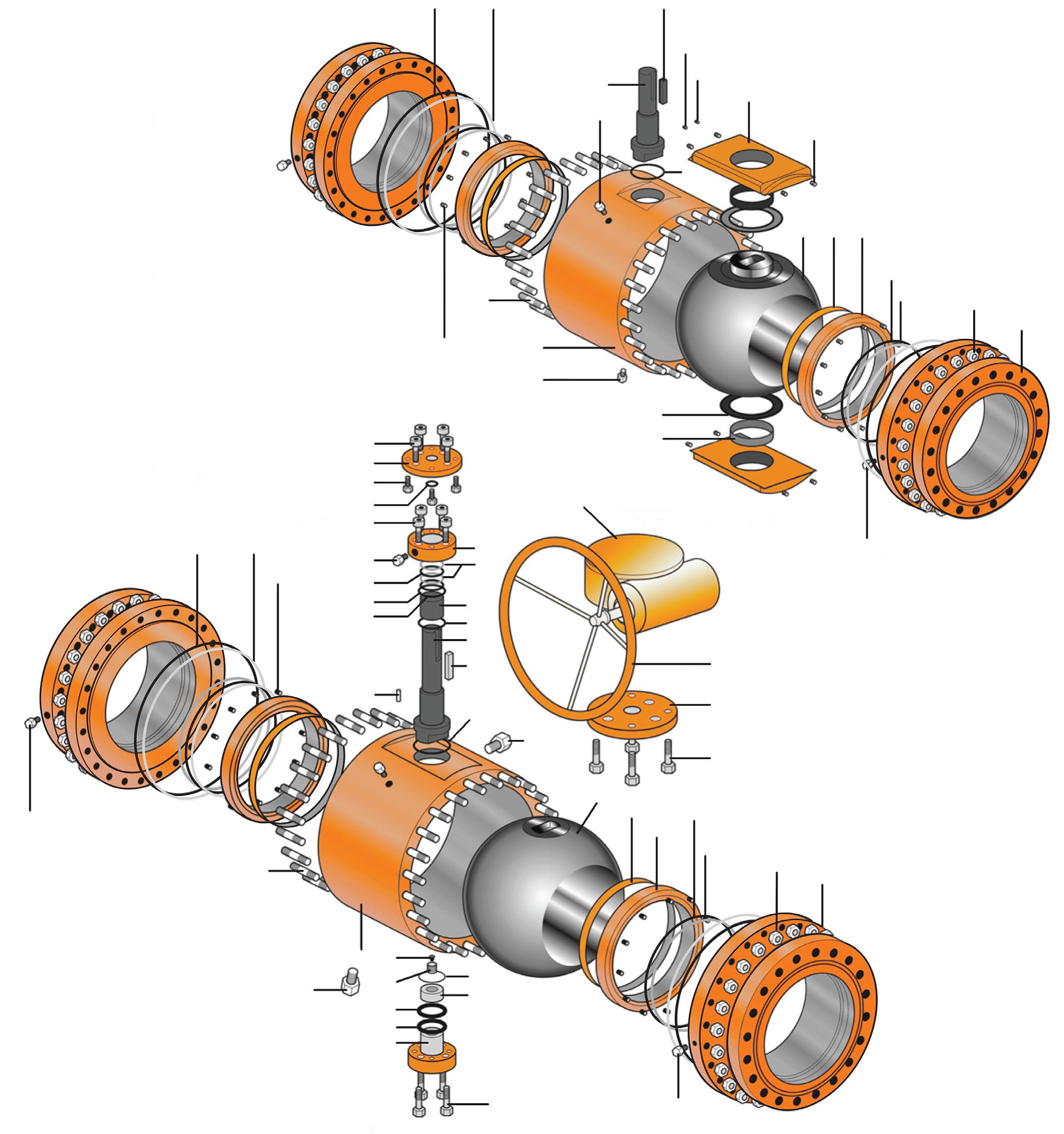
Part
Body
ASTM A216 WCB
Body (Adaptor) ASTM A216 WCB
Ball*
ASTM A182 F6A HF/HC
Stem* ASTM A182 F6A HF
Seat Ring*
ASTM A182 F6A + STL
Spring ANSI 6150 / Inconel
Gasket Graphite + 304
Stem Bearing Cu PB Alloy
Gland Nut ASTM A194 2H
O-Ring Viton / Graphite
Plug Carbon Steel
Gland Eyebolt ASTM A193 B7
Yoke ASTM A216 WCB
Gland Flange ASTM A216 WCB
Gland Stem ASTM A105/ENP
Packing Stem Graphite
Seat Gasket Graphite
Seat Ring ASTM A105/ENP
Bonnet Nut ASTM A194 2H
Bonnet Bolt ASTM A193 B7
Trunnion** A182 F6A + HF
Design and Manufacture ANSI B16.10 / API 6D
Face to Face Dimensions ANSI B16.5
Pressure Test API 598
* Can be Tungsten carbide, stellite, hard chrome, nitrided 900 Hv 0.3mm etc.
**Internal trunnion design depends on sizes/class
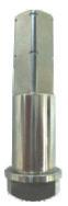
Stem
Hard Surfaced
Multi-Packing Design
Anti-Blow-Out
Anti-Static
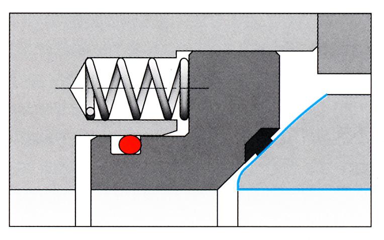
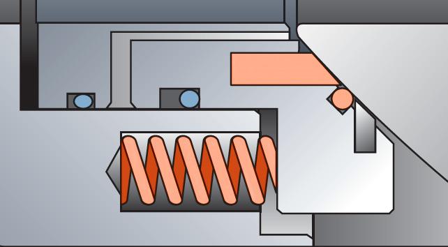
Seat Design
Designed to ‘scrape off’ and resist slurries, muds or other viscous fluids & solid mediums. Special Hardened Surface Treatment: Stainless Steel + HCr/TC/Stellite etc.
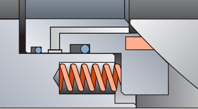
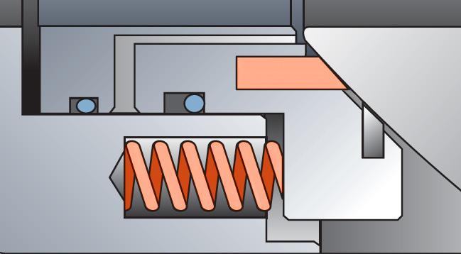
Seat Spring Design
Metallic energised design provides flexibility to stress and thermal expansion. Elastomer free for high temperatures will not jam like conventional coil springs.
Indicative design only. Numerous design configurations available depending on size class etc.
Flexible Graphite Stem Packing For Severe Services & High Temperature
Fire Safe Design

Ball
Hardened Surface Treatment Stainless Steel +HCr/TC/Stellite...etc. For High Temperature, Abrasive Services
Drain For drain or DB&B
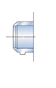
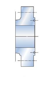
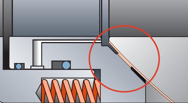
Slight roundness of the seat ensures continuity of contact.
due to differential pressure.
permanent contact provides seal irrespective of non-uniform deformation of the sphere.
This catalogue is an overview only. For full sizes, dimensions & materials please refer to the APV Ball Valve catalogue & APV Special Service Ball Valve catalogue. Click here As-built drawing can be supplied in accordance with specification requirements.
1/2” - 36” ANSI CLASS - 150/300/600/900/1500/2500


Design and construction conforms to API 6D specifications, tested to API 607 & 6D standards.
Independent loaded upstream and downstream seats provide a tight shut-off and allow the valves to be used for bi-directional flow. Spring loaded seat design provides low and high pressure sealing and body cavity pressure relief due to self relieving seat design.
Suitable for single or double block and bleed applications.
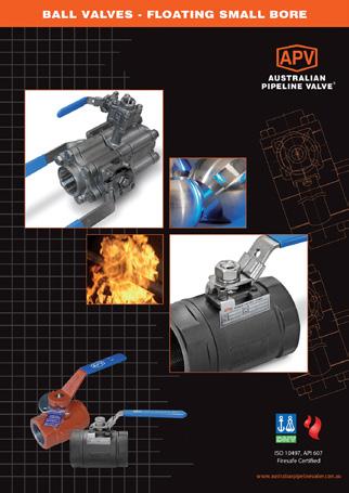
BVF100 Series 3 Piece Ball Valves have an emergency seal facility, blow-out proof stem, full through-conduit bore, electroless nickel plated or stainless trim and are anti-static. Stem and gland seals can be replaced in-line for ease of maintenance.
Available with locking devices, stem extensions, pipe pups, and actuation.
The full range of APV valves can meet NACE standard MR-10-75, latest edition if necessary.
APV was one of the first brands in the world to have firesafe certification to API 607 6th and 7th Edition, as well as being Firesafe Certified (DNV witnessed) to API 6FA 3rd Edition & ISO 10497-2010.
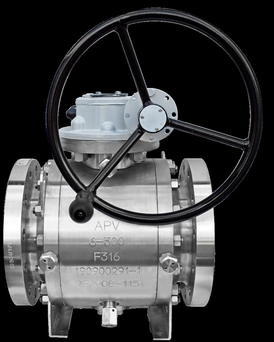
• Forged Construction
• Rugged Anti-Corrosive Gear Design
• Seat Lubrication Facility
• Body Bleed and Drain Ports
• Enclosed, Encapsulated Triple Barrier Stem Seals
• Blowout Proof Stem Design
• Emergency Stem Lubrication Fitting
• Self Lubricating PTFE coated Trunnion Bearings
APV seat inserts can be ordered in a variety of materials whilst still complying to API seat test requirements for “bubble-tight shut off” for oil & gas applications as well as specialised fluid transmission applications in chemical and mining sectors.
The A-PMSS+S® design is the same as the A-PMSS® above except for the addition of a scraper. On conventional trunnion ball valve seating systems, APV offers the PR-A-PMSS+S® seat design option (8” and above). A protective scraper ring is inserted in front of the soft seat insert to remove solid particles, dirt or debris that could damage or clog the contact area between ball and soft seat insert ring. This feature assures that the working area of the seat will be clean allowing the seats to work effectively. This design prolongs seat life whilst only minimally increasing cost & is particuarly advantageous for valves that cannot be removed from the line for repair such as buttweld valves, welded body valves, buried service valves as well as known non clean service applications.
APV Double or Triple seal seat design is ideal for applications that require redundant sealing when start up conditions are known to have debris in the line and where removing the valve is not possible. This design offers lower torque and superior low pressure shut-off whilst providing zero leakage reliability at an affordable price compared to metal seated. Multiple material types are employed for each seal providing a combination of resilient and superhard properties to deal with a wide range of entrained particulates and debris. Even if one or even two of the seals are damaged an effective seal can usually be maintained.
APV has extensive experience in the supply of valves for applications such as high temperature corrosive and/or erosive/abrasive environments. Various hard face material can be employed on the ball and seat face. Refer to the APV Special Service Ball Valve Catalogue.
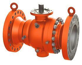
FLANGED / BW ENDS API 6D
• API 6D
• Flanged & Butt weld ends
• 3P split body, side entry
• Trunnion mounted ball, low operating torque
• Fire safe API 607, ISO 10497
• Anti-static device, BS 5351
• Double block & bleed
• Pressure self relieving seats
OPERATING CONDITION
Operating Temperature -29ºC~+185ºC*
Pressure Rating
PN 20, 50, 64, 100, 150
Class 150, 300, 400, 600, 900, 1500, 2500
* Low and high temperature service also available This is
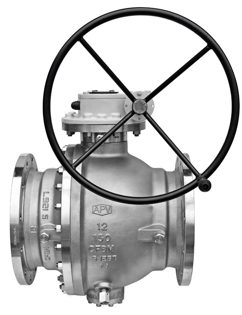
Conventional Trunnion Design

FIRESAFE CERTIFIED
Body materials Cast Steel (WCB), Stainless steel (CF8M) etc
Pressure rating ANSI 150, 300 & 600
Temperature 10°C ~ 500°C
Size 15mm ~ 300mm (1/2” ~ 8”)
Applications High temperature, Abrasive & corrosive
Services
Construction Stainless steel seat & ball, graphite gasket for body sealing, anti blow-out stem. Both seats are 304SS or 316SS stellited, nitrided or hard chrome. The ball is 304SS or 316SS stellited or hard chrome/nitrided. The stem is 304SS or 316SS or 17-4PH hardened/nitrided or stellited.
FEATURES
• Same face to face dimensions as API 6D standard teflon seated ball valves for easy changeover and replacement
• Quick 90° operation
• Full through flow - no obstruction to fluid, minimum pressure drop
• Long service life
1. Durability
The metal contact mechanism between ball and seat is ensured by spring energised seat and provides long life.
2. Half opening control
The metal mechanism enables the possibility of half opening the valve to control flow. Consult us, as options like V-Port may need to be considered. Also extreme wear through cavitation can occur when valve is in half open position.
3. Low torque operation
Small friction coefficient between ball and seat, and spring energised seats make manual operation easy.
4. Leakage
The seat is spring energised against the ball to maximise the effectiveness of the seat sealing process. Design is class V or VI and ISO 5208 rate A & AA shut off, uni-directional (also available bi-directional)
Description Material
Body
Adaptor (Tail)
Stem*
Seat*
Spring*
Spring
Packing
Gasket
Trunnion
Cap
Flange
Bracket
Adaptor
Gearbox
Lever
* Can be overlaid:- stellite, hardened chrome, tungsten carbide, nitrided to 900Hv 0.3mm etc.
TRUNNION STYLE (Usually 10” or 12” size only)
“Australian Pipeline Valve produces isolation, control and flow reversal protection products for severe and critical service media in utility, steam, pipelines, oil & gas and process industries. APV valves and pipeline products form the most competitive portfolio in the market.”