STRAINERS AND SIGHT GLASSES



Quality is Our First Priority.
Consistent product quality and a proven track record makes Australian Pipeline Valve a dependable choice where total reliability is the number one concern. Since its founding, APV’s philosophy has been focused on quality. Our valves are manufactured in full compliance to worldwide standards (such as ASME/ANSI, API, EN, ISO, BS, AS).


PRESSURE RATINGS
Fully ASME 150~600LB rated available up to ANSI 600 Class.
For body and glass ratings refer to drawing.
Flowturn sight glasses areavailable with full pressure rated and tested glass to match full ASME pressure rating.
APPLICATIONS
Water, oil water, air and gas. For corrosive/abrasive fluids check material grades for compatibility.
LININGS
Special linings, coatings on request.
END CONNECTIONS
Flanged AS Table D & E, EN, ISO, PN10, PN16, PN25, PN40, ASME 125, 150, 300, 600.

DIMENSIONS (MM) FLANGED SIGHT GLASS 300LB
Dimensions indicative only, refer to as-built drawing. 600LB available up to 300NB (12”), refer to drawing. 350NB~400NB refer todrawing.
Dimensions indicative only, refer to as-built drawing. * Reduced glass size option shown (C1), larger port available. 350NB~400NB refer todrawing.
GLASS
GASKET: TEFLON

Model SLSG (32~50 NB)
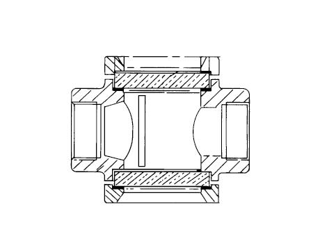
BODY
DIMENSIONS SCREWED SIGHT GLASSES (MM)

Model SLSG (15~25 NB)
BONNET/CAP (SCREW IN OR BOLTED)

BONNET/CAP (SCREW IN OR BOLTED)
* 1 Available in short, regular & long pattern
Design
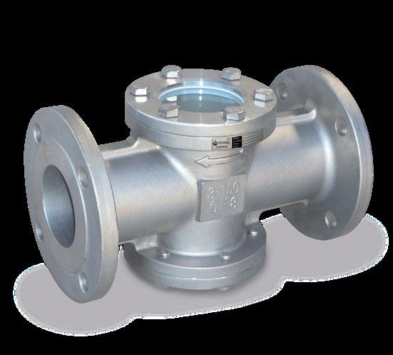
Fully integral body with full penetration welded process connection flanges. Certified borosilicate tempered glass type 3.3 as per ISO 3585.
Process Connections
ASME 150 to 600 class flanged ends, raised face, serrated finish. Also, available in AS 2129 Table D to H, AS 4087 and ISO 7005-1 PN 10 to 110.
Overview
Double sided high pressure tempered borosilicate sight glass. High strength, chemical durability, thermal resistance, 90% light transmission, outstanding chemical durability to acid and alkali, and environmentally friendly. Flow indicator is optional
DIMENSIONS & WEIGHT 300 CLASS MM & KG
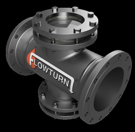
For 3D Video Click Here

DIMENSIONS & WEIGHT 600 CLASS MM & KG

* Pressure-temperature ratings applicable up to 200°C Pleas specify if special operating and environmental conditions
7
8
Manufactured in the USA, tempered borosilicate glass, type 3.3 per ISO 3585, has outstanding physical and chemical properties - low thermal expansion, high thermal resistance, excellent light transmission and impressive chemical durability. It is also a low-density glass that is 12% lighter than soda lime glass. Tempered glass demonstrates much higher material strength. When broken, it forms into finer pieces rather than sharp shards. Tempered glass can also withstand temperature fluctuations..


CHEMICAL RESISTANCE
Tempered borosilicate glass is resistant to almost any chemical attack. It is highly resistant to acidic and alkali solutions. Known chemicals that can cause corrosion on its surface is hydrofluoric acid, concentrated phosphoric acid and strong caustic solutions at elevated temperatures.
CHEMICAL COMPATIBILITY - BOROSILICATE CHEMICAL
CHEMICAL
1,4 Dioxane & Tetrahydrofuran E
2-Ethoxyethyl Acetate E
Acetic Acid, 25% E
Acetic Acid, Glacial E
Acetone E
Ammonium Hydroxide, 25% E
Amyl & Propyl Acetate E
Amyl Alcohol, Butanol E
Arsenic Acid E
Benzyl Alcohol E
Benzyl Benzoate E
Boric Acid, 10% E
Butyl Acetate E
Carbon Tetrachloride E
Chloroform E
Chromic Acid, 20% E
Dimethyl Sulfoxide E
Ethanol, 70% E
Ethanol, 98% E
Ethyl Acetate E
E – Excellent, F – Fair, NR – Non-Resistant
This table is just a guide
Tempered borosilicate glass can be operated safely at temperatures of 230°C, provided there is no sudden temperature shock. If PTFE bonnet gasket is used, maximum temperature is 200°C. Even though there is no exact rule applicable to all operating conditions, a maximum of 120°C temperature difference across the glass walls should be avoided.
Ethyl Ether
Ethylene Glycol
Formic Acid, 25%
Formic Acid, 85%
Glycerol
Hexane, Xylene
Hydrochloric Acid, 25% E
Hydrochloric Acid, Concentrated E
Hydrofluoric Acid, 35% NR NR
Isopropanol, n-Propanol
Isopropyl Ether
Isopropyl Myristate
Isopropyl acetone
Kerosene, Gasoline
Methanol, 98%
Methyl Acetate
2-Methoxyethyl Acetate
Methyl Chloride
Methyl Ethyl Ketone
Methyl Isobutyl Ketone
Freon
Nitric Acid, 25%
Nitric Acid, 50%
Nitric Acid, Concentrated
Phosphoric Acid 85%
Phosphoric Acid, 25%
Potassium Hydroxide
Propylene Glycol
Propylene Glycol Acetate
Sodium Hydroxide
Sodium Hydroxide
Sulphuric Acid, 25%
Sulphuric Acid, 95%
Sulphuric Acid, concentrated
Tetralin, Decalin
Toluene, Benzene
Trichloroacetic Acid, 10%
Trichloroethylene
Tricresyl Phosphate
Design
Bolted Bonnet, Full Bore metal to metal seating For Horizontal or Vertical (upward flow) Lines
Swing Type, API 6D or BS 1868
Renewable Seat Ring
Flanging
ASME 150 to 600 class flanged ends, raised face, serrated finish. Also available in AS 2129 Table D to H, AS 4087 and ISO 7005-1 PN 10 to 35.
Overview
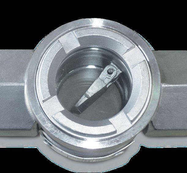
Single sided sight glass combination swing check (flapper serves as flow indicator as well as check valve)

DIMENSIONS 150LB
DIMENSIONS 300LB
*150NB & 200NB Class 300 are not full ANSI rated CWP see adjacent CWP table.
Features
Fully integral body
Patented shatter resistant carbonate sheet (30 times the impact strength of normal acrylic). Borosilicate may be used in some situations.
Description Carbon Steel Stainless
Body A216 WCB A351 Gr. CF8, CF8M
Cover A216 WCB A351 Gr. CF8, CF8M
Disc WCB - CR13 SS A351 Gr. CF8, CF8M
Hinge CR13 SS A351 Gr. CF8, CF8M
Hinge Pin CR13 SS A182 Gr. F304, F316
Plug A105 A193 Gr. B8, B8M
Cover Bolt A193 B7 A193 Gr. B8
Cover Nut A194 2H A194 Gr. 8F
Disc Nut A194 2H A194 Gr. 8, 8M
Washer Steel A276 Type 304, 316
Bonnet Gasket Spiral 316 + Gr. 7 Teflon or Spiral SS + Gr. 7
Seat (Integral) A105 + Stellite A351 Gr. CF8, CF8M
Glass MR5 Carbonate Sheet MR5 Carbonate Sheet
Standards
Face to Face / End to End ANSI B16.10
Flange Dimensions ANSI B16.5
Basic Design ANSI B16.34
Testing & Inspection API 598
Suitable for water, oil, gas etc up to 215°C or (300°C only with borosilicate or mica glass). Pressure limitations apply as temperature increases, consult us if over 50°C.

DIMENSIONS 600LB In 15NB to 20NB a male threaded integral sight glass bonnet inset is used
Sight Indicators fitted with standard MR5 glass should not be used on temperatures over 230°C. As with all materials, the pressure rating of these sight indicators will be reduced as the temperature increases above 40°C, it is essential you consult us if your application is for high temperature and or pressure service. It is essential you ensure the ANSI rating you order is suitable for the maximum pressure of your service. Note Class 150 300NB and 300 Class 150NB & 200NB are not full ANSI rated see CWP table above. For temperatures to 300°C we would offer Borosilicate or mica glass. We also supply borosilicate glass if application is for chemical service such as ketones, halogenated hydrocarbons, esters, aromatic hydrocarbons, aliphatic hydrocarbons, acids, amines, high concentration of alkalis & any other fluids not compatible with carbonated perspex. Please state your application.
at higher temperature, pressure rating decreases)
The catalogue is general in it’s nature and design and can vary at any time. This catalogue is to be used as a guide only.
Y-TYPE
CAST IRON, FLANGED TO SUIT 125LB ANSI B16.5 & AS/BS TABLE D, E, PN10/16
FLOW CHARACTERISTICS
Pressure drop in this chart has been calculated using a strainer with 1.6mm hole element on clean water. When the strainer element is partially blocked the pressure drop incurred will be inversely proportional to the area remaining clean
DIMENSIONS (MM)
For PN10/14/16/21 and AS Table D, E, F refer to drawing.
* Only a guide, will vary all sizes on request.
PRESSURE/TEMPERATURE
As per maximum pressure/temperature ratings indicated in relevant AS/BS/EN/ISO/ASME flange standard. Maximum Temp 220°C (pressure limitations apply at maximum temperature). All strainers are tested to 1.5 times the maximum working pressure. If for high temperature application you must advise so we can use high temperature gasket.
Y-TYPE STRAINER
CAST IRON, FLANGED TO SUIT 125LB ANSI B16.5 & AS/BS TABLE D, E, PN10/PN16
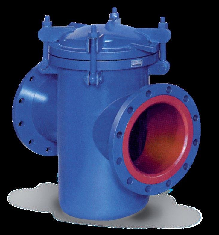
Flanged to Suit 125LB ANSI B16.5, AS 2129 Table D, E / AS 4087 / ISO 7005-1 / AS 4331.1 PN10 21. Y-Type cast strainers are manufactured with Heavy Duty Spot welded stainless steel punched screens. Suitable for water, oil & numerous fluid applications. Flowturn strainers have 10 times the open area of the nominal pipe bore. Multiply this by the ‘open area’ of the screen size to calculate total open area. On average, this gives Flowturn strainers 3 to 4 times the pipe bore open area when using standard hole perforation sizes.
Design ASTM F1200-88, BSEN 1074, ANSI B16.1, EN 12266-1. Service Recommendations These strainers are designed for long service. Installation of a strainer before any automatic equipment will ensure trouble free service and avoid the costly repairs or replacements so often caused by the introduction of foreign matter in pipe lines.
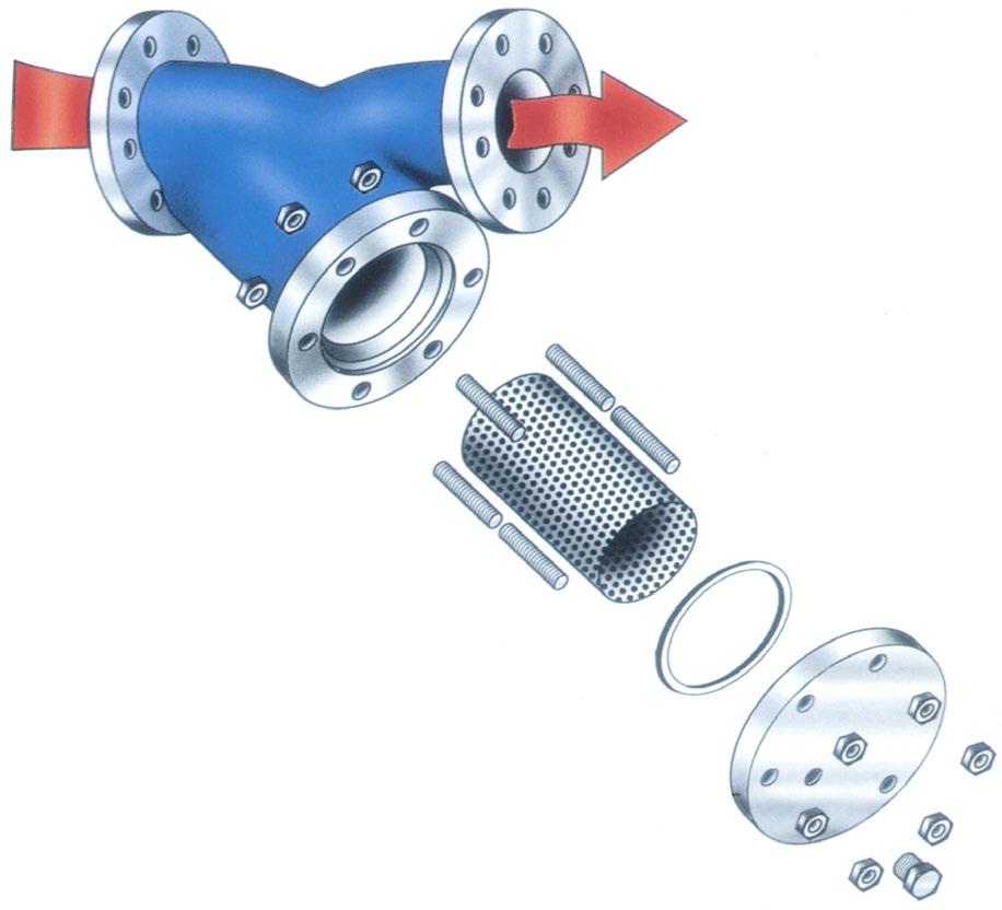
Features All sizes feature a bolted cover, as illustrated. Covers normally furnished with blowoff plug.
Screens Heavy gauge perforated stainless steel normally furnished with spot welded seams.
Flanging Available in ANSI B16.5, AS 2129 Table D/E, AS 4087/AS 4331.1/EN 1092-2/ISO 7005-1 PN10~16 (PN25 and 250LB also available in ductile iron & carbon steel).


Y-TYPE STRAINER
DUCTILE IRON/STEEL PN25 FLANGED & RATED
Y-Type cast strainers are manufactured with Heavy Duty spot welded stainless steel punched screens. Suitable for water, oil & numerous fluid applications. Flowturn strainers have 10 times the open area of the nominal pipe bore. Multiply this by the ‘open area’ of the screen size to calculate total open area. On average, this gives Flowturn strainers 3 to 4 times the pipe bore open area when using standard hole perforation sizes.
Service Recommendations These strainers are designed for long service. Installation of a strainer before any automatic equipment will ensure trouble free service and avoid the costly repairs or replacements so often caused by the introduction of foreign matter in pipe lines.
Features All sizes feature a bolted cover, as illustrated. Covers normally furnished with blowoff plug.
Epoxy coated internal & external.
Screens Heavy gauge perforated stainless steel normally furnished with spot welded seams.
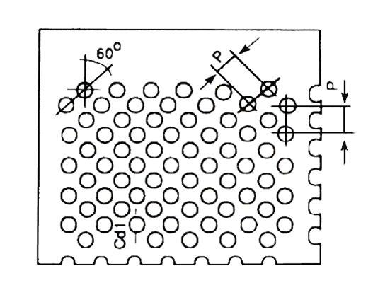
AVAILABLE SCREEN TYPES (SS MESH)
Flanging Available in: PN25 - AS 4331.1/EN 1092-2/ISO 7005-1, PN21 - AS 4087, PN35* - AS 4087 (PN25 rated, PN35 drilled), Table F - AS 2129.
*For true PN35 rating, refer 300 class WCB Flowturn strainer which can be supplied Flanged to suit PN35

Pressure Drop
When the strainer element is partially blocked the pressure drop incurred will be inversely proportional to the area remaining clean.

* Only a guide, will vary all sizes on request.
PRESSURE/TEMPERATURE
PN25 rated, maximum cold working pressure 2.5 mPa. Maximum Temp 220°C (pressure limitations apply at maximum temperature). All strainers are tested to 1.5 times the maximum working pressure. If for higher temperature application you must advise so we can use high temperature gasket.


Overview Y-Type cast strainers in WCB, CF8, CF8M, A20, Duplex, Super Duplex, monel, etc.. Heavy Duty spot welded S/S screens. Suitable for water, oil & numerous fluid applications.
Design Flowturn strainers have up to 9 times the open area of the nominal pipe bore. Multiply this by the “open area” of the screen size to calculate total “open area”. On average, this gives Flowturn strainers at least 3 times the pipe bore open area.
Also available with sight glass window.
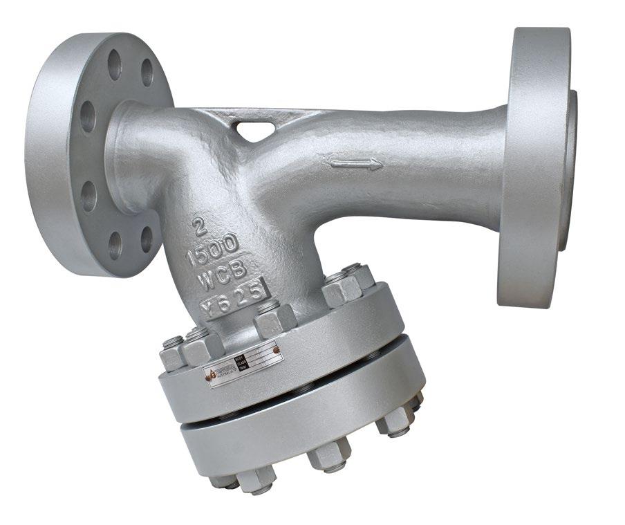
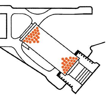
* Up to 50NB Bonnet is screw in (flanged on request)
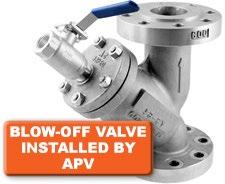


DIMENSIONS (MM)
SL-Y8111ANSI-150
SL-Y8111-3ANSI-300
SL-Y8111-6ANSI-600
SL-Y8111-15ANSI-1500
Larger sizes and 2500 class refer to drawing. Dimensions are provided as a guide and can vary any time without notice.
FLOW CHARACTERISTICS
Pressure drop in this chart has been calculated using a strainer with 1.6mm hole element on clean water
When the strainer element is partially blocked the pressure drop incurred will be inversely proportional to the area remaining clean
PRESSURE/TEMPERATURE
Flanged 1965 KPA (285 PSI) WOG 1034 KPA (150 PSI) @ 350°C (*2)
Flanged 4964 KPA (720 PSI) WOG 2068 KPA (300 PSI) @ 450°C (*2) 600 Class to 1500 Class please consult us.
All strainers are tested to 1.5 times the maximum working pressure. (*2) If for steam/high temp application you must advise so we can use high temp gasket. Pressure limitations apply at maximum temperature.
SCREEN SPECIFICATIONS (ALL 304/316 SCREEN)
We can also supply special mesh or bags as low as 37 microns for very low pressure/flow applications
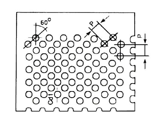
Overview Suitable for water, oil & numerous fluid applications. Flowturn strainers have up to 9 times the open area of the nominal pipe bore. Multiply this by the “open area” of the screen size to calculate total “open area”. On average, this gives Flowturn strainers 2-1/2 to 5 times the pipe bore open area. Strainers are furnished with a machined seat which allows the screen to be self aligning and assures a perfect fit. All sizes come complete with a blow-off connection* and an easily removable stainless steel screen.


DIMENSIONS (MM)
SL-Y8223 - 600/800 CLASS
DIMENSIONS (MM)
SL-Y8211 - 150, 600, 800 & 1000 PSI
Indicative only, refer to as-built drawing.
DIMENSIONS (MM)
SL-Y8223-1500 CLASS
Indicative only, refer to as-built drawing.
DIMENSIONS (MM)
SL-Y8223-2500 CLASS
Indicative only, refer to as-built drawing.
PRESSURE/TEMPERATURE
25NB ~ 50NB refer to as-built drawing.

Examples only. We can also supply special mesh as low as 37 microns for very low pressure/flow applications.

SLS503-150 150 Class (to Table-F)
280 PSI CWP (WOG)
170 PSI Saturated Steam (at 260°C)
SLS503-300 300 Class (to Table-J)
720 PSI CWP (WOG)
600 PSI Saturated Steam (at 260°C)
For superheated steam consult pressure/temp chart
SLS503-600 600 Class (to Table-R)
1440 PSI CWP (WOG) for high temperature consult chart
WC6 body supplied for high temperature applications
Maximum Temperature 850°F (450°C)
SLS503-900 900 Class
2220 PSI CWP (WOG) for high temperature consult chart
WC6 body supplied for high temperature applications
Maximum Temperature 850°F (450°C)
SLS503-1500 1500 Class
3700 PSI CWP (WOG) for high temperature consult chart
WC6 body supplied for high temperature applications
Maximum Temperature 850°F (450°C)
SCREEN SPECIFICATION (ALL 304 / 316 SS SCREEN)
Tested to API Standard 598
Face-to-Face Dimensions to ANSI B16.10
RF Flanged ends to ANSI B16.5
Butt Welding ends to ANSI B16.25
STANDARD MATERIAL SPECIFICATIONS
Body
Gasket
Bonnet
Bonnet Bolt
ASTM A216 WCB/A351 CF8M
S/S / Graphite
ASTM A216 WCB/A351 CF8M
ASTM A193 B7/A194 B8
Bonnet Nut ASTM A194 2H/A194 Gr. 8
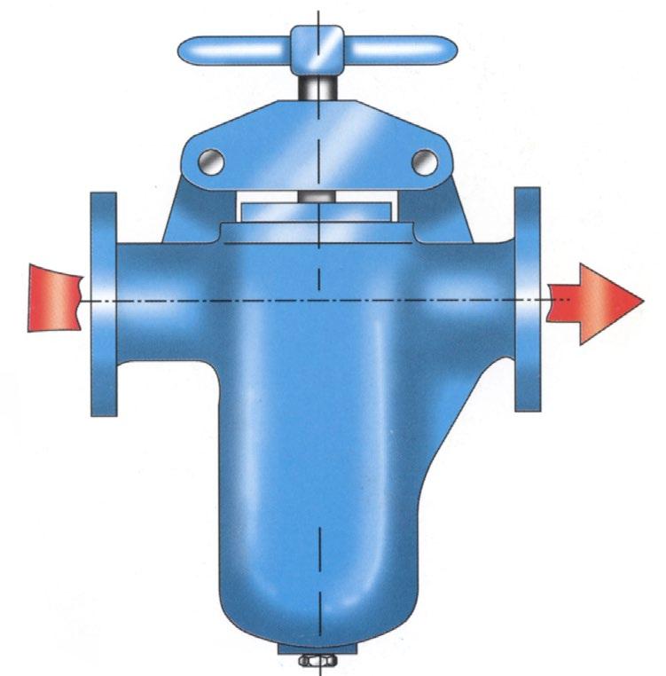
For horizontal or vertical installations in applications such as industrial, mining and mechanical services. Suitable for super-heated steam, H.T.H.W., steam, condensate & water.
Flowturn strainers have around 5 to 7 times the pipe bore open area. Multiply this by the ‘open area’ of the screen size to calculate the total open area. Smaller sizes have a larger open area (see attached). Integral cast body (not fabricated).

Std Weight Pipe




Flanging To Suit ANSI 125, 150 AS 2129 Table D, E, F AS 4087 PN14, PN21 AS 4331.1/EN 1092-1/EN 1092-2/ ISO 7005-1 PN10 ~ 25
STANDARD PRODUCT MATERIAL COMBINATION ANSI CLASS 150/PN21
Body, Cover, Plug ASTM B62 - Bronze/A216 WCB Screens SS316 Gasket CNAF/PTFE/NBR/EPDM
Body, Cover, Plug ASTM A216 Grade WCB Screens SS304 Gasket Non-asbestos (CNAF)
Body, Cover, Plug ASTM A351 Gr. CF8M Screens SS316 Gasket Non-asbestos (CNAF)
Class 300 model DKSL01 also available *
* Optional quick release lid (Bridge type shown)
SIZE 50NB to 500NB (2”-20”)

CLASS 150 PRESSURE & TEMPERATURE
Simplex Strainers 25~300NB (1” to 12”) Pressure drop strainers with 3/32” or 1/8” perforated baskets
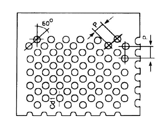
SCREEN

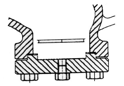
Basket type cast strainers in WCB, CF8 & CF8M Heavy Duty spot welded S/S screens. Suitable for water, oil & numerous fluid applications.
The WFL basket strainer has many unique design features including: Spot faced flange bolt holes, plugged bottom drain vent, cast-in support legs (larger sizes), encapsulated cover gasket and an optional quick opening cover design.
Minimal Pressure Loss
Pressure loss is minimised by providing a slanted straining element design and straight flow path.
Large straining capacity
With its large body and sizeable straining element, the WFL has the ability to store large quantities of debris without affecting pressure loss - thus maximising time between servicing.
Self-cleaning option
Utilising a modified straining element, the bottom drain can be fitted with a ball valve to allow for the automatic cleaning or flushing of the straining element while keeping the pipeline in service.
Refer to detailed drawing.

When the strainer element is partially blocked the pressure drop incurred will be inversely proportional to the area remaining clean
PRESSURE/TEMPERATURE
SL-WFL 150B -150LB Flanged 1965 KPA (285 PSI) WOG 1034 KPA (150 PSI) @ 350°C
SL-WFL 300B - 300LB Flanged 4964 KPA (720 PSI) WOG 2068 KPA (300 PSI) @ 450°C
SL-WFL 600B - 600LB Flanged 9928 KPA (1440 PSI) WOG 4136 KPA (600 PSI) @ 350°C 900 Class to 1500 Class please consult us.
All strainers are tested to 1.5 times the maximum working pressure. If for steam/high temp application you must advise so we can use high temp gasket. Pressure limitations apply at maximum temperature.

Example only, can supply any size mesh. We can also supply special mesh or bags as low as 37 microns for very low pressure/flow applications

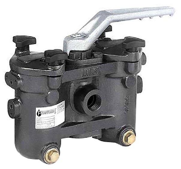

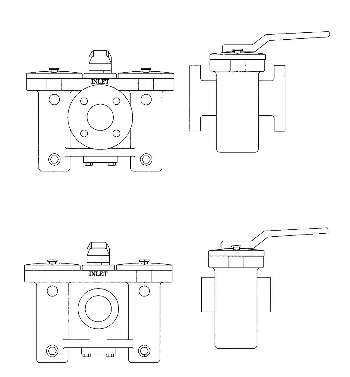
ANSI CLASS 125, PN16 - ANSI CLASS 150, PN20
ANSI CLASS 250, PN25 - ANSI CLASS 300, PN40
Flowturn Integral Duplex Dual Basket Strainer is designed for use in fluid handling systems where the flow cannot be shut down for basket cleaning.
A lubricated plug valve enables the flow to be switched to either basket allowing the alternate basket to be cleaned while isolated from the flow path.
PRESSURE & TEMPERATURE
Ductile Iron Body and Cover, CF8 Plug, PTFE or Viton Seal, SS304 Basket
Carbon Steel Body and Cover, CF8 Plug, PTFE or Viton Seal, SS304 Basket
CF8 Body and Cover, CF8 Plug, PTFE or Viton Seal, SS304 Basket SS304
CF8M Body and Cover, CF8M Plug, PTFE or Viton Seal, SS306 Basket
Bronze Body and Cover, CF8M Plug, PTFE or Viton Seal, SS306 Basket


Straightener / Flow Conditioner, L>6D
Conventional Set
APPLICATION
PN10 & PN16
Prevents damage to water meters by filtering the water entering water meter. Increase water flow rates measuring accuracy of water meters.

MAIN FEATURES & BENEFITS
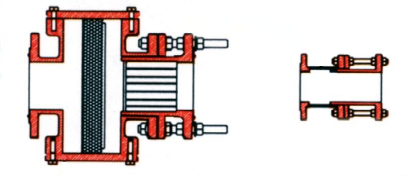
Stainless steel flow conditioner pipe set, able to reduce turbulent flow and creating laminar flow, thus increasing flow rates measuring accuracy of water meters. See Figure 2.
Stainless steel strainer mesh.
Built-in expansion joints allow flexible movements of the distances between flow meter, allowing ease of assembly.
Fusion Bonded Epoxy Powder (FBE) coating body.

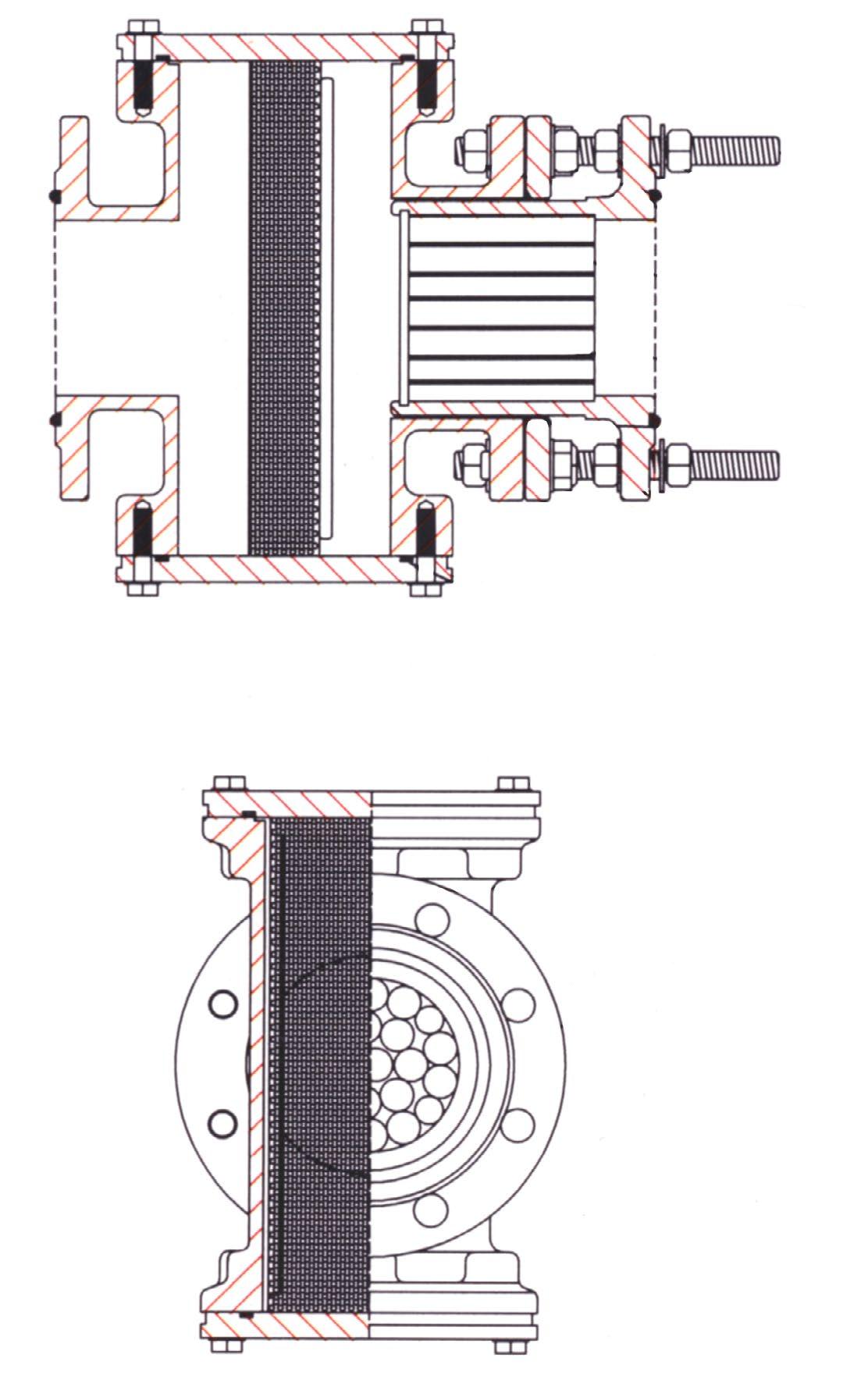
DIMENSIONS

Magnetic Screen Inserts for added protection against fine ferrous metal particles.
• For extra protection for your hydraulic systems, pumps and other process & industrial applications.
• Magnetic screen assemblies prevent fine ferrous metal particles from passing through the screen and damaging bearings, seals, seats and other machined or soft surfaces.
• The magnets in these screen assemblies are positioned to obtain the strongest magnetic field possible, resulting in the most effective particle retention.
CHANNEL MAGNET
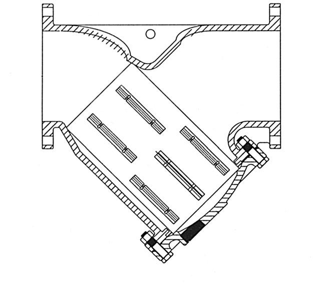
“Y” Type - Sizes 65NB to 450NB (2-1/2 to 18”)
ROD MAGNET

CHANNEL MAGNET

Basket Type - Sizes 80NB to 450NB (3” to 18”)
50NB & 65NB (2” & 2-1/2”) Sizes use Horseshoe Magnets
HORSESHOE MAGNET
6mm (1/4”) Dia. Magnet
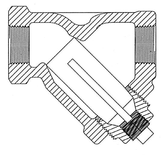
“Y” Type - Sizes 15NB to 80NB (1/2 to 3”)

Horseshoe Magnet

“Y” Type - Sizes 40NB to 80NB (1-1/2 to 3”) Magnet Spacer
QUANTITY
Stainless steel bolts are used to assemble magnets to the screen. Magnets are equally spaced in each row. When two or more rows are used, the magnets are offset. Magnet material is Cast Alnico #5 or equivalent.
Rod magnet, “Y” type 15NB to 80NB Horseshoe magnet, 40NB to 80NB
Channel magnet, 65NB to 450NB and “Basket” type 80NB to 450NB
Magnetic screen assemblies are used with stainless steel screen material only.
The blow-off connection (drain) is integral with the magnet holder for rod or horseshoe type magnets. However with the Bolted Bonnet version a side drain can also be supplied.
Australian Pipeline Valve don’t consider in our design the following factors of risk:
1. APV-Flowturn ‘Standard’ Iron sight glasses and strainers can be used in a temperature range between -10 to +100°C up to 200°C depending on seals. (Note, pressure limitations apply above 38°C refer to Pressure/Temperature charts.) Australian Pipeline Valve-Flowturn ‘Standard’ iron valves are not suitable for low temperature service below -10°C. Steel and other grades of steel are as per ASME B16.34 but temperature is also limited by gaskets and seals.
2. The onus is on the customer to specify all materials of construction and service conditions. Australian Pipeline Valve shall assume standard materials and conditions if not otherwise specified.
3. Australian Pipeline Valve ‘Standard’ strainers and sight glasses are not equipped with devices suitable to avoid internal over-pressures caused by incorrect operations of process or by-fluids & liquids subjected to an increase of volume and/or pressure and/or blockage.
4. Australian Pipeline Valve ‘Standard’ strainers and sight glasses are not designed with special devices to withstand a sudden thermal jump (thermal shock).
5. In general Australian Pipeline Valve ‘Standard’ strainers and sight glasses are not mechanically designed to bear overloads due to exceptional atmospheric or natural phenomenon’s (such as earthquakes).
6. In general Australian Pipeline Valve ‘Standard’ strainers and sight glasses are not designed to bear loads on flanges, on pipe connections or pipe-line.
7. The compatibility between the strainers and sight glasses construction materials and medium is selected by the user. The user is ultimately responsible for verifying the compatibility between medium and materials.
8. Abrasive or dirty service applications need to be considered and stated at time of order.
9. The installation shall be designed to provide adequate means of draining and venting to avoid harmful effects such as water hammer, vacuum collapse, corrosion and uncontrolled chemical reactions and to permit cleaning, inspection and maintenance in the correct manner.
10. Strainers and sight glasses have not been designed to include corrosion, erosion or abrsion alowances.
11. The piping system shall be so designed to reduce the risk of fatigue due to vibration of pipes.
12. APV-Flowturn strainers are suitable for liquid working pressures specified (cold working pressure ‘cwp’j) on drawing and only when used in hydraulic installations in which shock is absent or negligible.
Strainers and sight glasses are not designed to operate under high shock loadings. Where pressure increases occur due to shock loading (water hammer), they should be added to the working pressure to obtain the total pressure acting on the valve. The total must not exceed the pressure rating of the valve. A pressure surge, or shock, is usually caused by the rapid closure of a check valve or quarter turn valve resulting in a sudden reduction in flow rate.
Where shock is likely to occur, the maximum shock pressure should be added to the working pressure (‘cwp’j) of the line to determine working pressure of products in the line...also, hydraulic installations should be equipped with air chambers or other types of shock absorbers to eliminate, as much as possible, increase in pressure due to shock.
Maximum operating pressure reduces as service temperature increases. Pressure and temperature limitations are as per ASME B16.34 or ASME B16.1 and as shown on the drawing - gaskets and internal components all reduce temperature rating. Cold working pressure or class is shown on the identification plate and drawing, and must not be exceeded.
j Cold Working Pressure ‘cwp’ : where ‘Cold Working Pressure’ is the maximum rated pressure of the valve at a temperature up to 65°C (150°F). Pressure rating shown on drawing, labels and certificate is always cold working pressure non-shock.
START-UP
Before installing the strainer onto the pipe-line it is mandatory, for the user, to verify the compatibility of the strainer or sight glass with service conditions (medium, temperature and pressure). With reference to standard strainers held in stock, the reseller and end user will have to assure themselves of the compatibility between the strainer and the conditions required by the customer.
Before using the valve in a potential explosive atmosphere it’s necessary for the customer to: -
• To verify the correct type of strainer or sight glass is specified.
• To verify the compatibility between the strainer and the zone in which the strainer or sight glass should be installed
• To foresee the pipe-line ground condition on which the strainer or sight glass should be installed
• To check that the temperature if the valve surface is not higher than the flammable point of the atmosphere in which the strainer or sight glass is installed (in this case specify an insulating cover device for the strainers)
• To avoid mechanical knocks during the installation that may cause sparks.
Australian Pipeline Valve cannot be held responsible for damage caused by use of the product for any reason, especially if it is improper use or modified.
“Australian Pipeline Valve produces isolation, control and flow reversal protection products for severe and critical service media in utility, steam, pipelines, oil & gas and process industries. APV valves and pipeline products form the most competitive portfolio in the market.”
