Quality is Our First Priority.
Consistent product quality and a proven track record makes Australian Pipeline Valve a dependable choice where total reliability is the number one concern.
Since its founding, APV’s philosophy has been focused on quality. Our valves are manufactured in full compliance to worldwide standards (such as ASME/ANSI, API, EN, ISO, BS, AS).

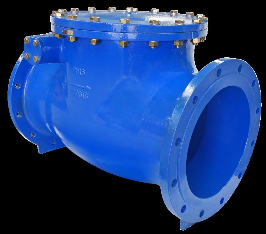
Table D - SL404-D
Table E - SL404-E
Table F - SL404-F
PN10 - SL404-10
PN14 - SL404-14
PN16 - SL404-16
PN21 - SL404-21
PN35 - SL404-35
125 Class SL404-125
150 Class SL404-150 250 Class SL404-250
DIMENSIONS & WEIGHTS
Design
BSEN 12334 (BS 5153), MSS-SP71 Type 1
Flanging/Pressure Class
ANSI B16.1 125lb, 150lb, 250lb.
ANSI B16.42 150lb, 250lb.
AS 2129 table D, E, F, H. AS 4087 PN14, PN16, PN21, PN35.
ISO 7005-1, PN10, PN16, PN25. AS 4331.1 PN10, PN16, PN25. EN 1092-2 PN10, PN16.
Face to Face Dimensions
ASME B16.10, EN 558-1 Series 10, EN 12334 (BS 5153) (AS 4794 on request)
Test Standard
AS 4794, EN 12266-1, MSS-SP71, ISO 5208, API 598.
Ductile Iron Body for 250 Class and PN16 in larger sizes.
Soft Seat also available DIN 3202/3352 F6 Face to Face Dimension
Design
BSEN 16767 (BS 5153), ANSI B16.42 (Wall)
Flanging/Pressure Class
AS 4331.1 PN25
ISO 7005-I PN25
EN 1092-2 PN25
AS 2129 Table F
AS 4087 PN21, PN35 (PN25 rating)
Face to Face Dimensions
EN 16767 (BS 5153), EN 558-2 (AS 4794 on request)
Test Standard
EN 12266-1, ISO 5208
DIMENSIONS & WEIGHTS
Refer to drawing for other dimensions.
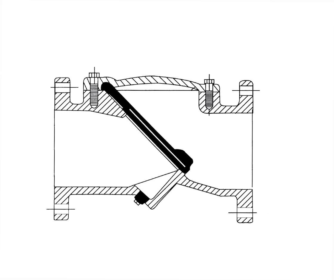
SWING CHECK VALVE
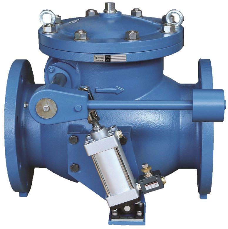
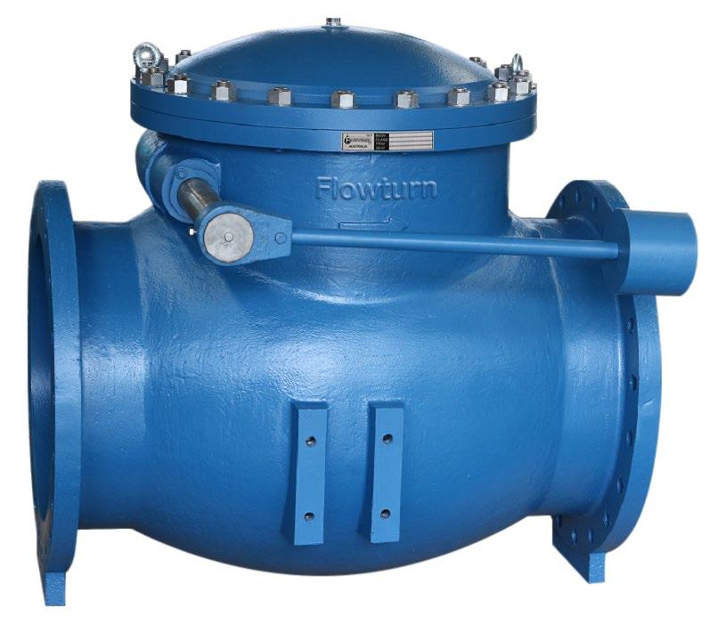
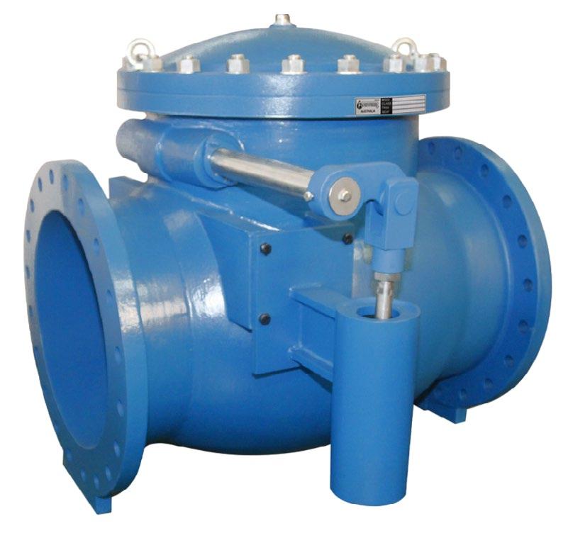
Table D - SL404-D-CW
Table E - SL404-E-CW
PN10 - SL404-10-CW
PN14 - SL404-14-CW
PN16 - SL404-16-CW
PN21 - SL404-21-CW
PN25 - SL404-25-CW
125 Class SL404-125-CW
150 Class SL404-150-CW
250 Class SL404-250-CW
Design
BSEN 16767 (BS 5153), MSS-SP71 Type 1, ANSI B16.1
Flanging/Pressure Class ANSI B16.1125lb, 150lb, 250lb ANSI B16.42 150lb, 250lb AS 2129 table D, E, F, H AS 4087 PN10, PN14, PN16, PN21, PN35 ISO 7005-1, PN10, PN16, PN25 AS 4331.1 PN10, PN16, PN25 EN 1092-2 PN10, PN16, PN25 JIS B2220 5K, 10K, 16K, 20K Face to Face Dimensions
ASME B16.10, EN 558-1, EN 558-2, EN 16767 (BS 5153) (AS 4794 on request)
Test Standard AS 4794, EN 12266-1, MSS-SP71, ISO 5208, API 598
Ductile Iron Body for 250 Class and PN16 in larger sizes.
Table D, Table E
Table F, Table H
Design
ASME B16.34/BS 1868 Flanging
ANSI B16.5, Also available in AS 2129 Table D to H and AS 4087/ISO 7005-1 PN 10 to 35
Face to Face Dimensions
ANSI B16.10
Inspection & Test API 598
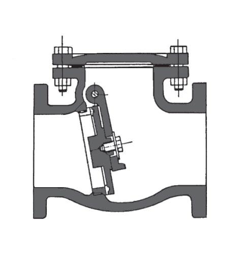
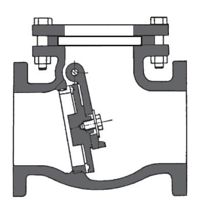
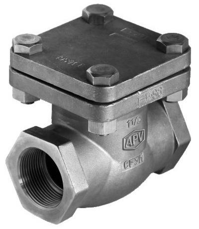
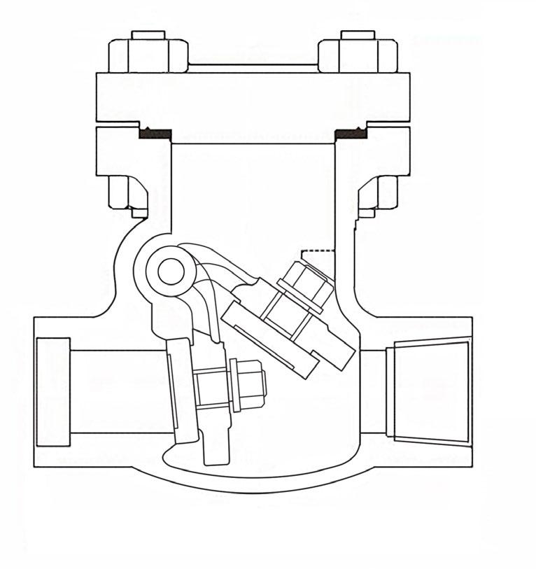
Design
Bolted Bonnet, Full Bore metal to metal seating For Horizontal or Vertical (upward flow) Lines
Swing Type, API 6D or BS 1868
Renewable Seat Ring
Flanging
ASME 150 to 600 class flanged ends, raised face, serrated finish. Also available in AS 2129 Table D to H, AS 4087 and ISO 7005-1 PN 10 to 35.
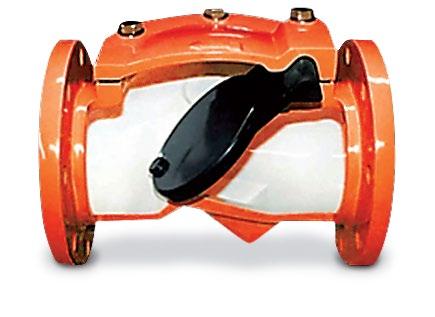
Overview
Single sided sight glass combination swing check (flapper serves as flow indicator as well as check valve)
DIMENSIONS 150LB
Features
Fully integral body
Patented shatter resistant carbonate sheet (30 times the impact strength of normal acrylic). Borosilicate may be used in some situations.
Description Carbon Steel Stainless
Body A216 WCB A351 Gr. CF8, CF8M
Cover A216 WCB A351 Gr. CF8, CF8M
Disc WCB - CR13 SS A351 Gr. CF8, CF8M
Hinge CR13 SS A351 Gr. CF8, CF8M
Hinge Pin CR13 SS A182 Gr. F304, F316
Plug A105 A193 Gr. B8, B8M
Cover Bolt A193 B7 A193 Gr. B8
Cover Nut A194 2H A194 Gr. 8F
Disc Nut A194 2H A194 Gr. 8, 8M
Washer Steel A276 Type 304, 316
Bonnet Gasket Spiral 316 + Gr. 7 Teflon or Spiral SS + Gr. 7
Seat (Integral) A105 + Stellite A351 Gr. CF8, CF8M
Glass MR5 Carbonate Sheet MR5 Carbonate Sheet
Standards
Face to Face / End to End ANSI B16.10
Flange Dimensions ANSI B16.5
Basic Design ANSI B16.34
Testing & Inspection API 598
Suitable for water, oil, gas etc up to 215°C or (300°C only with borosilicate or mica glass). Pressure limitations apply as temperature increases, consult us if over 50°C.
*1 Larger diameter on request
*2 300NB Class 150 is not full ANSI CWP rated, see adjacent table.
DIMENSIONS 600LB
*150NB & 200NB Class 300 are not full ANSI rated CWP see adjacent CWP table.
In 15NB to 20NB a male threaded integral sight glass bonnet inset is
DIMENSIONS 300LB (note at higher temperature, pressure rating decreases)
Sight Indicators fitted with standard MR5 glass should not be used on temperatures over 230°C. As with all materials, the pressure rating of these sight indicators will be reduced as the temperature increases above 40°C, it is essential you consult us if your application is for high temperature and or pressure service. It is essential you ensure the ANSI rating you order is suitable for the maximum pressure of your service. Note Class 150 300NB and 300 Class 150NB & 200NB are not full ANSI rated see CWP table above. For temperatures to 300°C we would offer Borosilicate or mica glass. We also supply borosilicate glass if application is for chemical service such as ketones, halogenated hydrocarbons, esters, aromatic hydrocarbons, aliphatic hydrocarbons, acids, amines, high concentration of alkalis & any other fluids not compatible with carbonated perspex. Please state your application.
up to
on your inquiry and your order. COLD WORKING
If a higher pressure is required you must specify in
The catalogue is general in it’s nature and design and can vary at any time. This catalogue is to be used as a guide only.
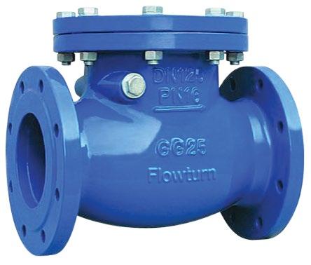
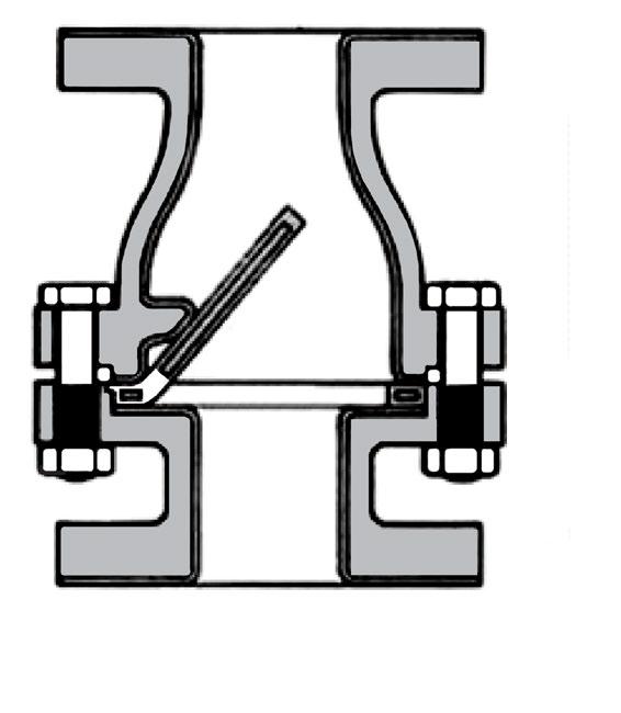
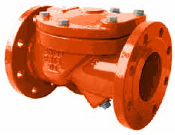
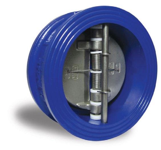
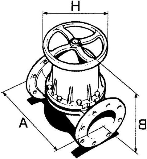
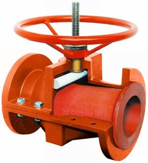
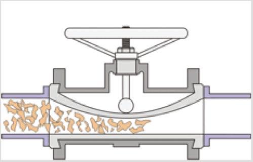
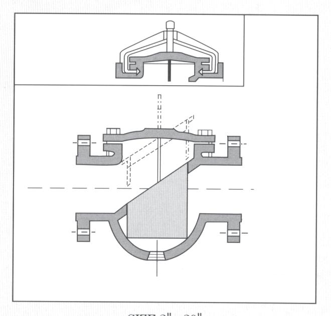
Cast Iron or rubber lined cast iron body, semi flexible disc swing check. Design BS 5158, BSEN 12334.
RANGE OF APPLICATION
Flanging
Connecting dimensions & thickness to ANSI(ASA)/BS/AS/EN/ISO specifications to suit ANSI B16.1, EN 1092-2, PN 6~16, AS 4087 PN 14~16, AS 2129
Table D to E, ISO 7005-1 PN 6~16, AS 4331.1 PN 6~16.
MATERIAL LIST
Body/End Piece Cast Iron IS: 210Gr. FG. 260 with hard/soft rubber lining
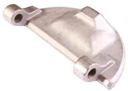
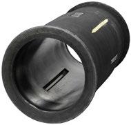
Disc (or flap) Steel reinforced plate rubber lined. Available in neoprene, viton, teflon etc.
Connecting bolts/nuts Steel IS: 1367, Gr. 4.6/4
Valve Surface protection Prime coat: chlorine-free with modified alkyd resin.
Linings Available Food grade, halar, hard rubber, teflon etc.
FEATURES
Simple three parts design, with only one moving part. Disc, absolutely 100% leak tight, 0.035 bar back pressure. Full bore design for minimum flow turbulence. Flap also serves as gasket seal between body and end piece. Valve usable in vertical or horizontal plane. Down time is kept to a minimum as the flap can easily be replaced in minutes.
DIMENSIONS
Rubber lining specification according to flow medium & working temperature. Cast on flow direction arrow ensures correct installation. When placing order, please specify flow medium, working pressure and working temperature. Not recommended for use under vacuum pressure.
The catalogue is general in it’s nature and design and can vary at any time. This catalogue is to be used as a guide only.
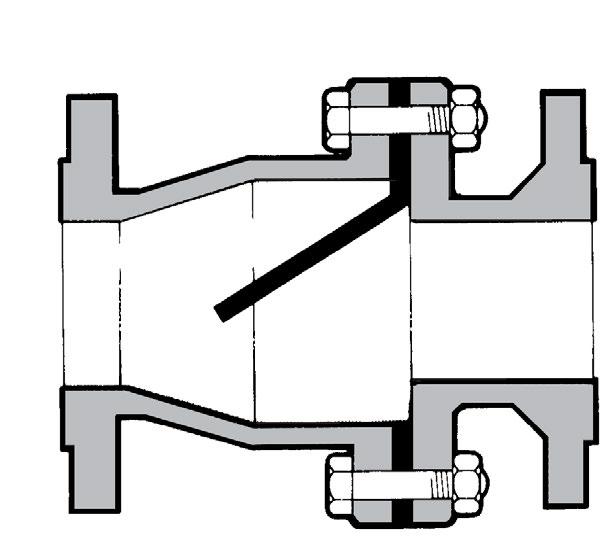
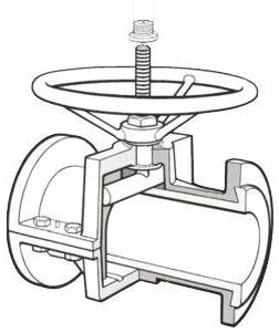
Cast Iron or rubber lined cast iron body, semi flexible disc, swing check. Flow reversal of plus 0.35 bar. Design BS 5158, BSEN 12334.
RANGE OF APPLICATION
Flanging
Connecting dimensions & thickness to ANSI(ASA)/BS/AS/EN/ISO specifications to suit ANSI B16.1 125LB, EN 1092-2, PN 6~16, AS 4087 PN 10~16, AS 2129 Table D to E, ISO 7005-1 PN 6~16, AS 4331.1 PN 6~16. EN 1092-2 PN 6~16.
MATERIAL LIST
Body/End Piece Cast Iron IS: 210 Gr. FG. 260 with hard/soft rubber lining
Disc (or flap)
Steel reinforced plate rubber lined. Available in neoprene, viton, teflon etc. Grade “B” Butyl is standard.
Connecting bolts/nuts Steel IS: 1367, Gr. 4.6/4
Valve Surface protection Prime coat: chlorine-free with modified alkyd resin.
Linings Available Food grade, halar, hard rubber, teflon etc.
FEATURES
Simple three parts design, with only one moving part. Disc, absolutely 100% leak tight, 0.035 bar back pressure. Full bore design for minimum flow turbulence. Flap also serves as gasket seal between body and end piece. Valve usable in vertical or horizontal plane. Down time is kept to a minimum as the flap can easily be replaced in minutes.
DIMENSIONS
Rubber lining specification according to flow medium & working temperature. Cast on flow direction arrow ensures correct installation. When placing order, please specify flow medium, working pressure and working temperature. Not recommended for use under vacuum pressure.
The catalogue is general in it’s nature and design and can vary at any time. This catalogue is to be used as a guide only.
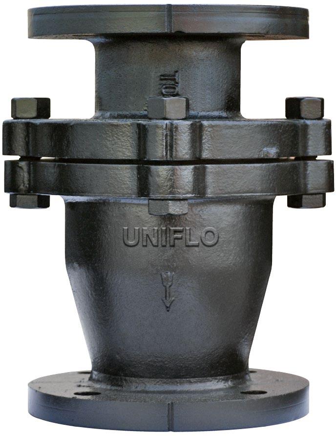
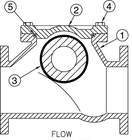
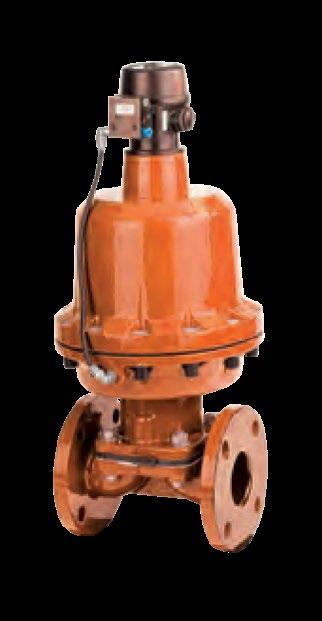
CHECK VALVE - UNIFLO
Design
MSS-SP71, BSEN 16767 (BS 5153), BSEN 1074, ANSI B16.1/ANSI B16.42
Features
100% full flow area. Resilient lined body optional.
Flanging/Pressure Class
ANSI B16.1 125lb, 150lb
ANSI B10.42 150lb, 250lb
AS 2129 Table D, E, F AS 4087 PN14, PN16
ISO 7005-1, PN10, PN16
AS 4331.1 PN10, PN16
EN 1092-2 PN10, PN16
JIS B2220 5K, 10K, 16K, 20K
Face to Face Dimensions
ASME B16.10, EN 558-1, EN 16767 (BS 5153) (AS 4794 available)
Test Standard
AS 4794, EN 12266-1, MSS-SP71, ISO 5208, BSEN 1074
Pressure/Temperature Rating
Nitrile 16 bar from -10 to 100ºC
EPDM 16 bar from -10 to 120ºC
Viton 16 bar from -10 to 200ºC
MATERIALS
1 Body Cast Iron/Ductile Iron ASTM A126
2 Cover Cast Iron/Ductile Iron ASTM A126 Class B Over 12” ASTM A53B-Gr65-45-12 Ductile Iron+FBE
3 Gasket Graphite or Butyl Rubber etc. on request
4 Disc Buna/EPDM/Viton/NBR ASTM
5 Bolt Steel AISI 1035/SAE Grade 5
6 Inner Coat Epoxy or Lined Epoxy or Chloro Butyl or Bromo Butyl etc
7 Plug Malleable Iron (Optional)
8 Hinge Pin Stainless Steel AISI 31655
* Body material is available in Ductile iron (14 inch and over is standard in ductile iron)
DIMENSIONS 125LB/150LB
*Based on 500 Series, alternative face to face also available. *1Flanging as per AS/BS/EN/ISO as required. Refer to drawing for Table D to F and PN10 to PN21.
Design
BSEN 16767 (BS 5153), BSEN 1074
Features
100% full flow area. Resilient lined body optional.
Flanging
ISO 7005-1 PN25
AS 4331.1 PN25
EN 1092-2 PN25
AS 2129 Table F, H AS 4087 PN21, PN35
Rating
2100kPa CWP 50~80NB
2000kPa CWP 100NB
1600kPa CWP 150NB
1000kPa CWP 200~250NB
Face to Face Dimensions
EN 558-1, EN 16767 (AS 4794 also available)
Test Standard
AS 4794, EN 12266-1, MSS-SP71, ISO 5208, BSEN 1074, API 598
Pressure/Temperature Rating
Nitrile 25 bar from -10 to 120ºC
EPDM 25 bar from -10 to 120ºC
Viton 25 bar from -10 to 200ºC
MATERIALS
* Based on 500 Series, alternative face to face also available.
*1Alternative flanging as per AS/EN/ISO as required, refer to drawing.

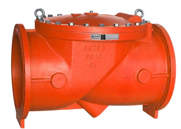
Application
Suitable for all types of water, air & steam 100oC. (For higher temperature, consult us.)
Features
Sizes DN 50 ~ DN 600mm (2”~24”)
Flanging
Flange Drilling to suit
ANSI B16.1, ANSI B16.5, BS EN 1092-2, BS 10, AS 2129 D/E and AS 4087 PN 10/14/16.
Test Standard
MSS-SP71 Class 250 & EN 12334 PN16
Optional Accessories
Proximity Switch, Backflow Actuator, Oil Dash-pot, Air Release Plug on the Cover.
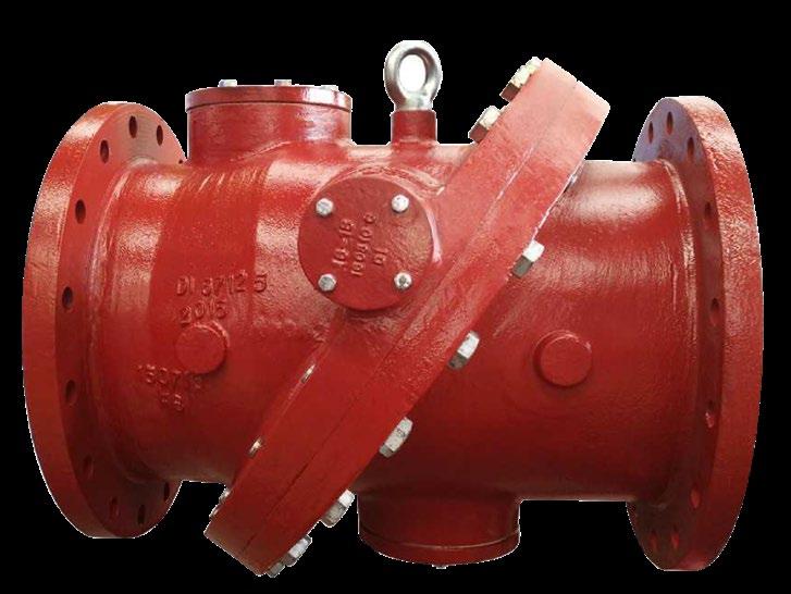
The unique design of the hi-strength fabric reinforced rubber flapper disc creates an elastic spring to close-against the flow, combined with the tilted body seat (closing angle 35o) act to reduce the closing time, minimise the water hammer and flow reversal. Simplicity of design with three components (body, disc & cover) in one valve, and disc, hinge and pin are integral and fully encapsulated with special rubber for maintenance free, longlife, 1,000,000 continuous cycles tested with no sign of wear or distortion to the valve side and seat, body and cover are ductile iron. This valve will operate trouble free for a longer period compared to conventional check valves.
Valves are manufactured and tested in accordance with EN 12334 PN10/16/25, TIS
383 PN6/10/16, MSS-SP 71 class125/250 and also meet the requirements of AWWA C508. The tilting disc and 2 piece bodies designed check valve accomplishes full flow opening by having the disc pivot or tilt in the flow media. The opening stroke range in much less than that of the conventional swing check valves, therefore reduces opening and closing time critical to controlling flow reversal and reducing water hammer. The full flow area with lower headloss ensure valve will operate with the highest efficiency and durability.
FEATURES
Sizes are available from DN 80 mm - DN 1800 mm. (3”-72”)
Flange drilling to suit ANSI B16.1, EN 1092, BS 10, ANSI B165, AS 2129 Table C to E and AS4087 PN 10 to 16.
Epoxy coating to AWWA C210-84 standard.
Optional accessories Signal switch, By-pass, Hydraulic cyclinder (top/bottom/side mounted)
Uniflo Tilted Disc Check Valve provides energy efficient operation, while easily handling the most severe and demanding applications with features such as: non-slam closure, wear resistance, leak tight seating and versatility of operation.
1 Body
3
4 Sleeve
5
(MM & INCH)
Other Size or Pressure, Refer to Drawing.
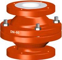
APPLICATION & CHARACTERISTICS
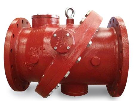
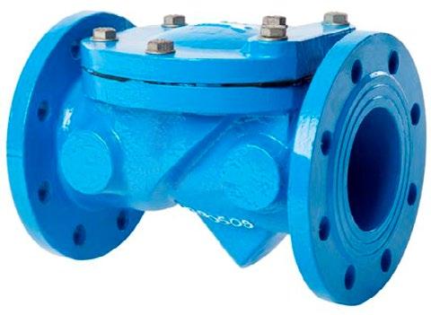
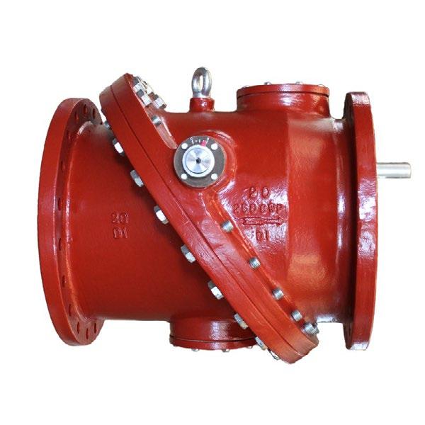
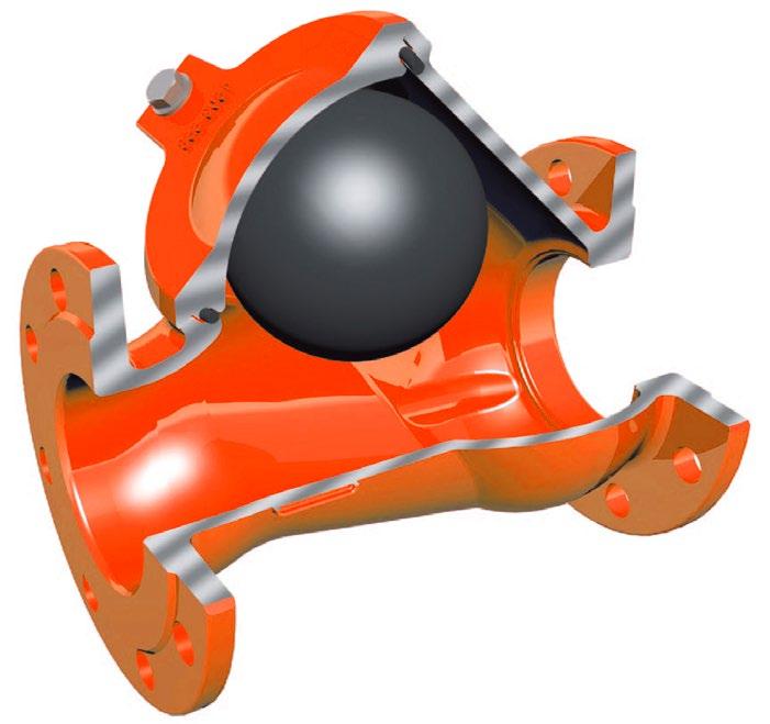
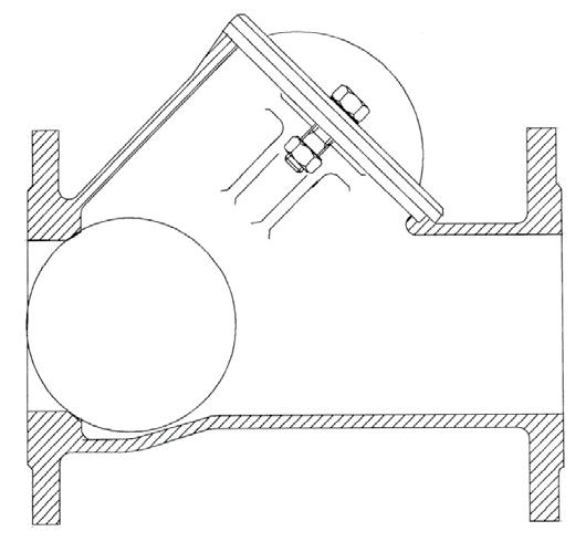
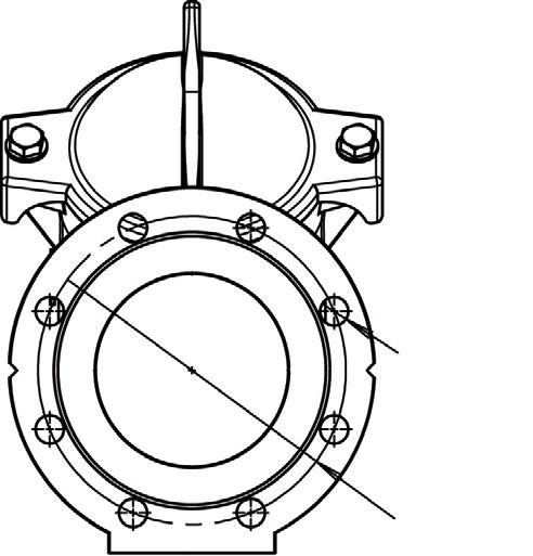
These full port ball checks with uninterrupted flow (equal to bore of pipe) are resistant to clogging and are ideal for wastewater, stormwater treatment, pumping dirty fluids. There is no accumulation of debris/deposits and the valve can be cleaned in-line without removal of entire valve and other neutral liquid applications. They can be used in horizontal & vertical service. BC series check valves have a low head loss and are self-cleaning due to the rotating ball.
Flanging
ANSI B16.1 125lb, 150lb AS 4087 PN14, PN21 AS 2129 Table D, E, F
AS 4331.1 PN10, PN16, PN25
EN 1092-2/ISO 7005-1 PN10, PN16, PN25
Face to Face Dimensions
EN 558-1 Series 48 - was DIN 3202-F6 (Dimension L1) AS 4794 (Dimension L), AS 3 579, ANSI B16.10
1 1 Body Ductile
2 1 Bonnet Ductile iron plus Epoxy Coat EN-GJS-400-15
1563 EN-JS 1030
3 1 Ball Nitrile or EPDM coated steel Polyurethane
4 2/4 Nut Stainless steel
5 1 Gasket Nitrile or EPDM
6 1 Degassing plug Stainless steel Optional
Stainless body and PTFE/PFA/FEP coated ball available on request for chemical and high temperature applications.
STANDARDS
Manufacture according to the requirements of the European directive 97/23/CE (Equipment under pressure): category III modulate H. (DN 40-400)
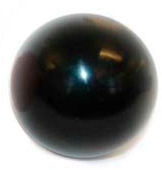
Balls used in Uniflo ball check valves are NBR or EPDM vulcanised with an iron, steel or aluminium core PTFE/PFA coated ball also available.
- 16 bar after lining (Hydro.)
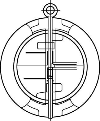
125LB, PN10, PN14 & PN16 RATED
Rating API 594 - Class 125/150 or AS/EN/ISO/BS PN10/PN14/PN16
Design API 594, BSEN 16767
Max temp -18°C* to 100°C Buna - N, -18°C* to 110°C EPDM, -18°C* to 121°C metal seat (As Body).
Flanging To suit ASA 125, 150, EN 1092-2
PN10/PN16, AS 2129 Table D, E, AS 4087 PN14/ PN16/PN21, ISO 7005-1 PN10/PN16, AS 4331.1 PN10/PN16, EN 1092-2 PN10/PN16, JISB 2220 5K~20K
Face to Face EN 558 (was DIN 3203-K3), BSEN 16767 or EN 16782 (3202-K3) or ASME B16
Test API 598/ISO 5208/MSS SP67-1
Metal seated leakage 3CC/min/inch of valve size per API 598.
Soft seated leak tight shut off.
* Iron body limitation -18°C
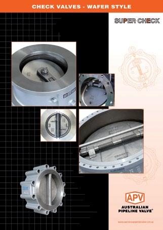
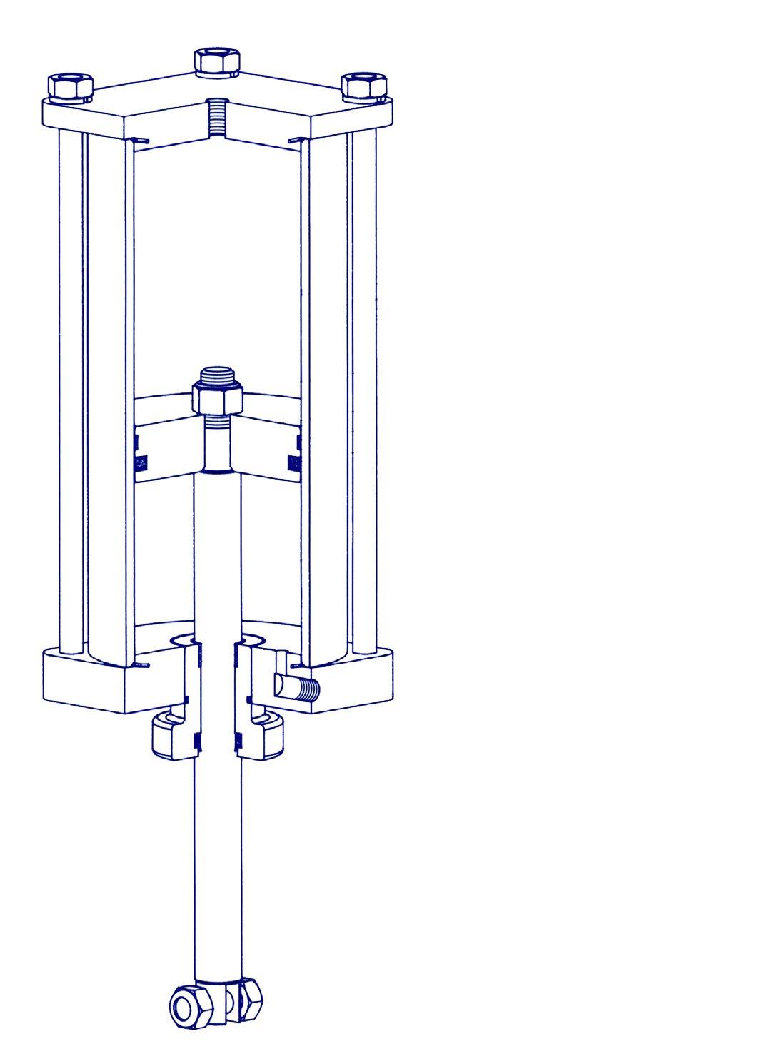
DESIGN FEATURES
• Encapsulated and bonded body seat (soft seat)
• Upper and lower PTFE thrust bearings
• Dual springs for quicker activation long life and even distribution of force over both plates
• Fusion bonded epoxy coated body (internal & external)
• Long leaf springs (prevent rubbing of disc and seat)
• Alleviation from Water Hammer
Reaction of torsion spring makes plates rapidly close prior to the start of reverse flow of fluid due to the stop of power, thus prevents damage from water, hammering caused by pumps and other reciprocating devices.
• Lower Head Loss
Designed with optimum venturi to reduce head loss when compared with similar Dual Plate Type Check Valves.
• Installation Directions
In addition to the compact size, SUPER-CHECK valves can be installed either horizontally or vertically.
• Long Leg Torsion Spring
Action which allows the plates to open and close without seat scrubbing.
• Super-Check provide a complete range of sizes from ND40 through ND 1800, designed and rated in accordance with ANSI 125 LB, PN10, PN14, PN16, PN21
BILL OF
Part Name Materials
Body Iron 126 Class B, Ductile Iron+FBE
Plate Bronze, 304SS, 410SS, 316SS, Duplex, iron
Springs (Long Leg) 316SS 4 Pin 304SS or 316SS 5 Body Seat NBR (BUNA), EPDM, Viton, Metal 7 Bearing PTFE 9 Retainer S25C or S/S
Eye Bolt SS41
O-Ring Viton, NBR, EPDM
Ensure the valve is at least eight pipe diameters from reciprocating or
SLIM PLATE DESIGN
Standard in all sizes. Ensures lower cracking pressures & large flow rates.

PN10 SL600-10
PN14 SL600-14
PN16 SL600-16
PN21 SL600-21
PN35 SL600-35
Table D SL600-D
Table E SL600-E
Table F SL600-F
125 Class SL600-125
150 Class SL600-150
250 Class SL600-250
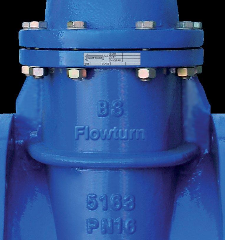
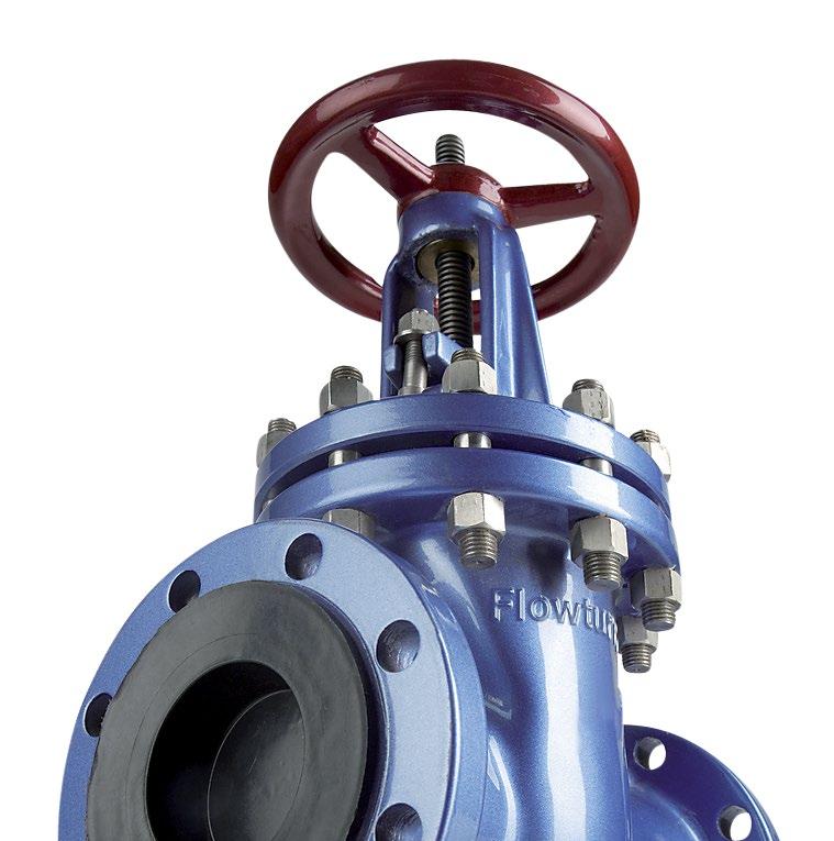
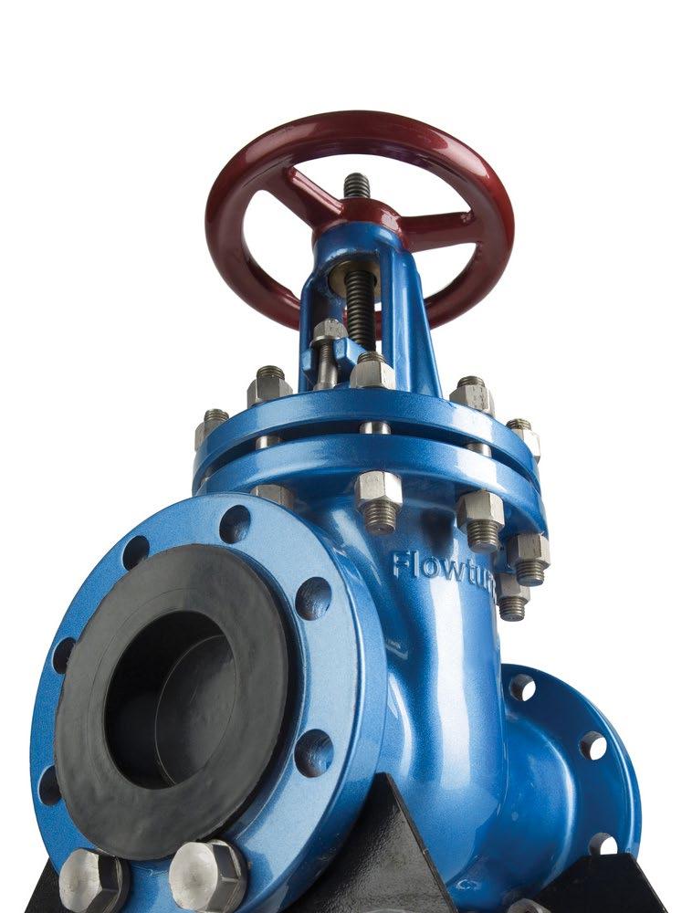
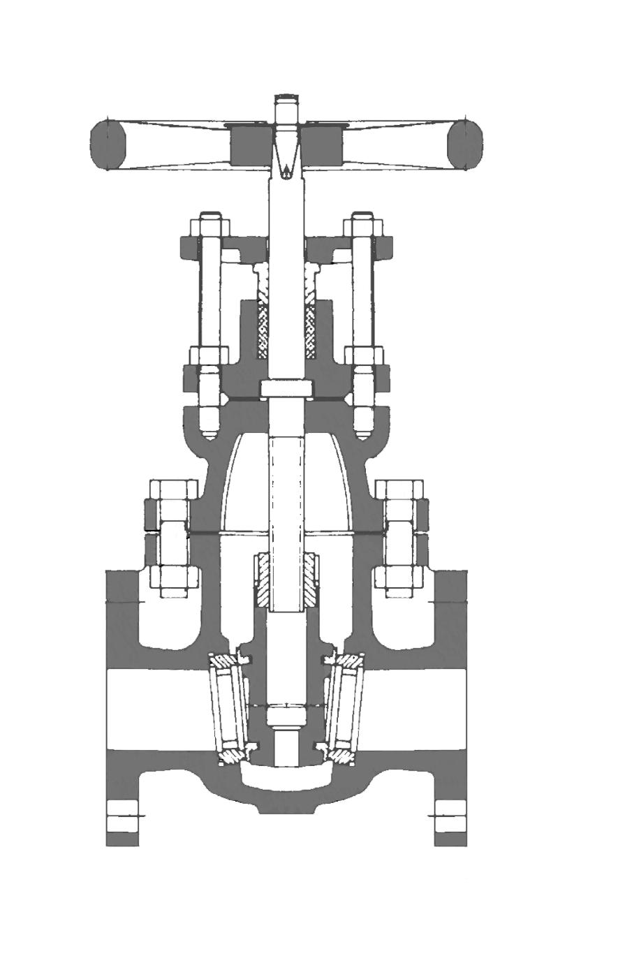
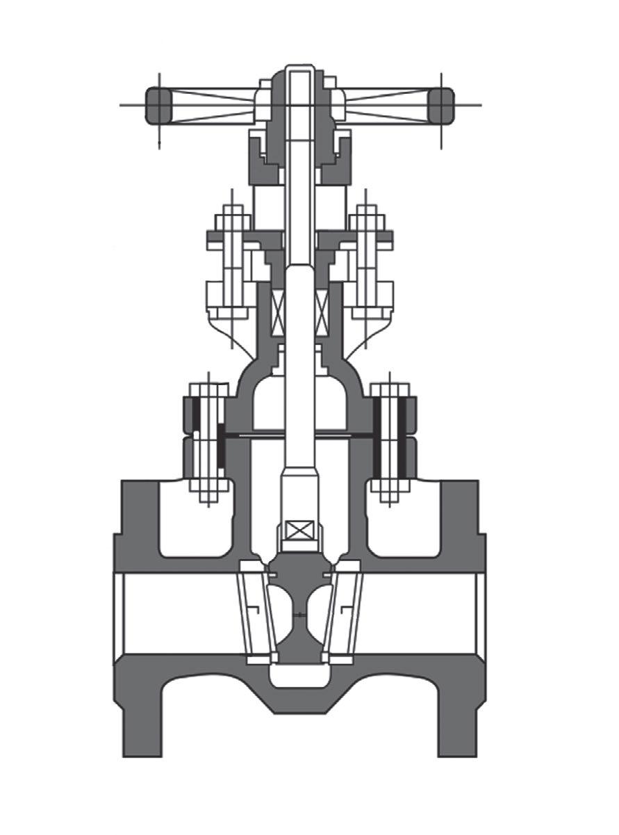
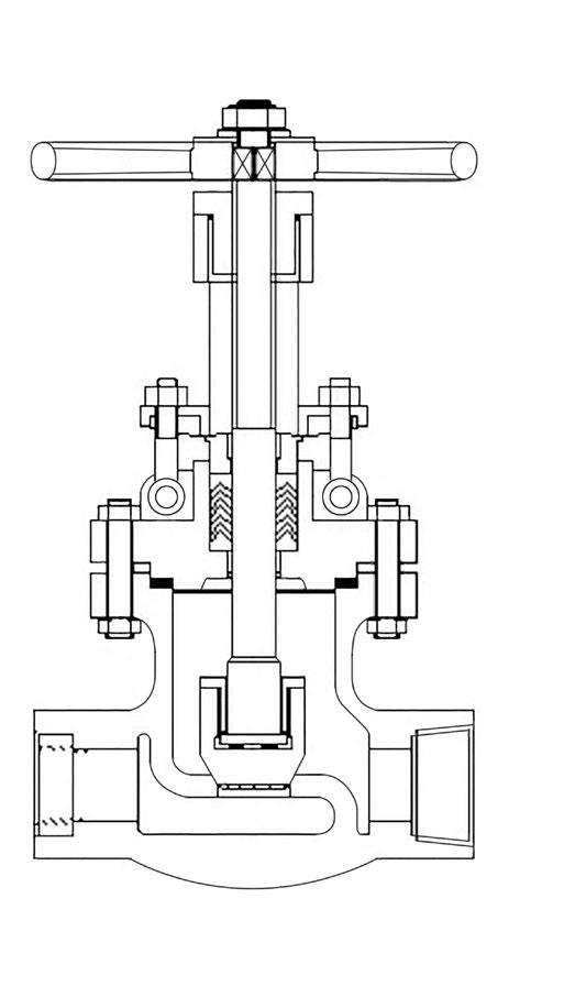
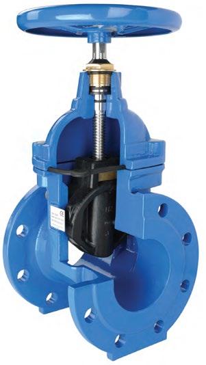
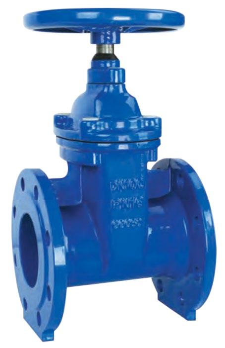
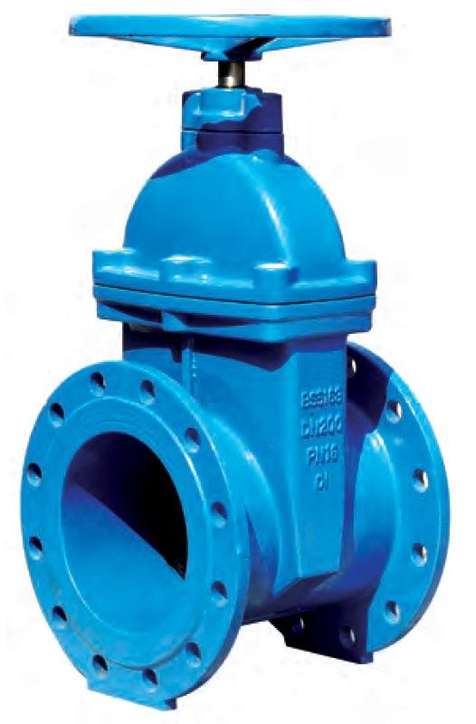
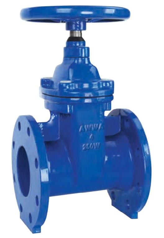
Design MSS SP70-1, MSS SP-128, BSEN 1171 (BS 5150), AS 2638.1
Features
Inside screw & yoke, solid wedge, bolted bonnet, non-rising stem.
Flanging/Pressure Class
ANSI B16.1 125lb, 150lb, 250lb ANSI B16.42, 150lb, 250lb AS 2129 Table D, E, F, H AS 4087 PN14, PN16, PN21, PN35 AS 4331.1 PN10, PN16
EN 1092-2 PN10, PN16
ISO 7005-1, PN10, PN16 JIS B2220 5K, 10K, 16K, 20K Face to Face Dimensions EN 1171 (BS 5150), ASME B16.10, AS 2638.1, EN 558-1, MSS SP70.
DIMENSIONS & WEIGHTS
NOTE: Indicative drawing only. Detailed drawing & bill of material can be furnished on request
1 Body ASTM A126 Class B/A395
2 Seat Ring ASTM B62 (bronze*)
3 Wedge Face Ring ASTM B62 (bronze*) 4 Wedge ASTM A126 Class B 5 Stem* Bronze/Brass/F6/420 6 Body Gasket Graphite/NBR
Bolt Steel B7 8 Nut Steel 2H 9 Bonnet ASTM A126 Class B/A395 10 Gasket PTFE/Graphite
11 Packing Graphite/PTFE
Packing Gland
Gland Flange Nut Alloy Steel 2H
Gland Flange Cast Brass/410SS
Yoke Bushing Nut
NOTE: *Bronze B16 or stainless steel CR13/304/316 refer to drawing. **For gear operator refer to drawing. †Optional, refer to drawing.
PN21 SL600-21 PN25 SL600-25 Table F SL600-25-F
DIMENSIONS
Design BSEN 1171, AWWA C500-09.
Features 2500KPA CWP. Inside screw & yoke, solid wedge, bolted bonnet, non-rising stem.
Flanging/Pressure Class
AS 4331.1 PN25
EN 1092-2 PN25
ISO 7005-1 PN25
AS 2129 Table F
AS 4087 PN21, PN35 (PN25 rated)
Face to Face Dimensions EN 558-1 Series 24.
MATERIAL LIST
(bronze*)
Wedge Face Ring ASTM B62/BS1400 LG2 (bronze*)
Gasket Graphite/Full Face Nitrile
NOTE: *Bronze B16 or stainless steel CR13/304/316 refer to drawing. † Optional, refer to drawing.
NOTE: Indicative drawing only. Detailed drawing & bill of material can be furnished on request
PN10 SL601-10
PN14 SL601-14
PN16 SL601-16
PN21 SL601-21
Table D SL601-D
Table E SL601-E
Table F SL601-F
125 Class SL601-125
150 Class SL601-150
250 Class SL601-250
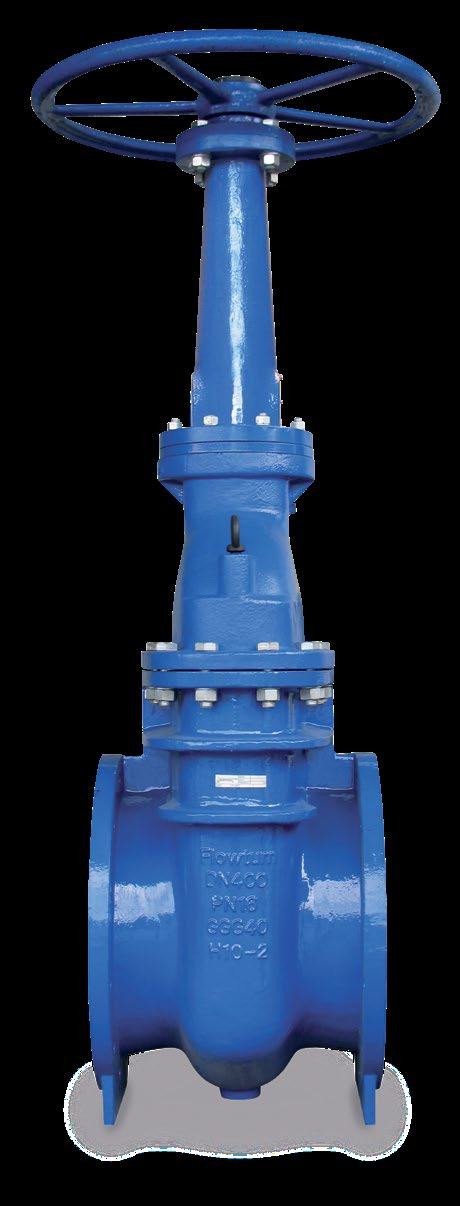
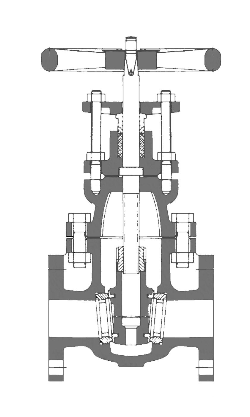
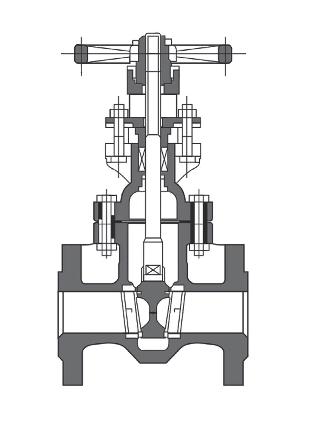
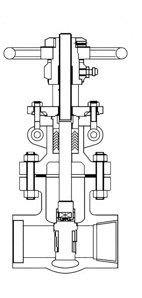
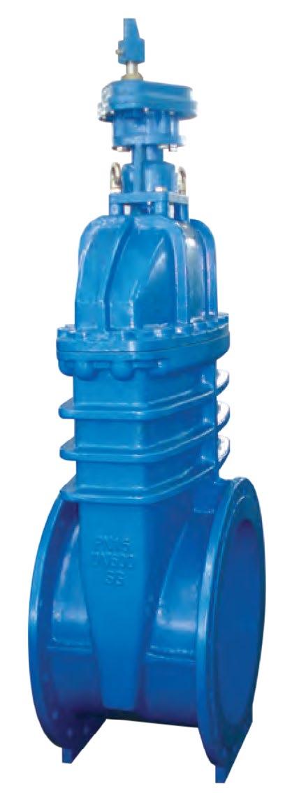
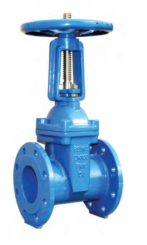
Design
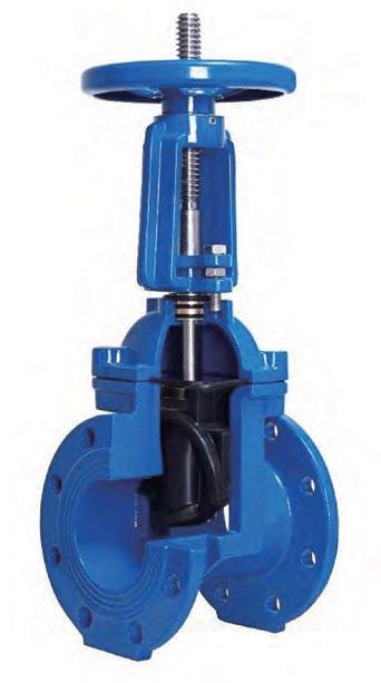
MSS SP70-1, MSS SP-128, BSEN 1171 (BS 5163), AS 3579, AS 2638.1 AWWA C500-09.
Features
Outside screw & yoke, solid wedge, bolted bonnet, rising stem.
Flanging/Pressure Class
ANSI B16.1 125lb, 150lb, 250lb ANSI B16.42, 150lb, 250lb AS 2129 Table D, E, F, H AS 4087 PN10, PN14, PN16, PN21, PN35
AS 4331.1 PN10, PN16 EN 1092-2 PN10, PN16
ISO 7005-1, PN10, PN16 JIS B2220 5K, 10K, 16K, 20K Face to Face Dimensions EN 1171 (BS 5163), ASME B16.10, AS 2638.1, EN 558-1, MSS SP70.
D, Table E
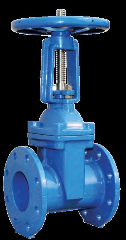
Design
BSEN 1171, AWWA C500-09.
Features
2500 kPa CWP. Outside screw & yoke, bolted bonnet, rising stem.
Flanging/Pressure Class
AS 4331.1 PN25
EN 1092-2 PN25
ISO 7005-1 PN25
AS 2129 Table F
AS 4087 PN21, PN35 (PN25 rated)
Face to Face Dimensions
EN 558-1 Series 24.
NOTE: Indicative drawing only. Detailed drawing & bill of material can be furnished on request. *Closed.
PN10 SL201-10
PN14 SL201-14
PN16 SL201-16
PN21 SL201-21
PN35 SL201-35
125 Class SL201-125
150 Class SL201-150
250 Class SL201-250
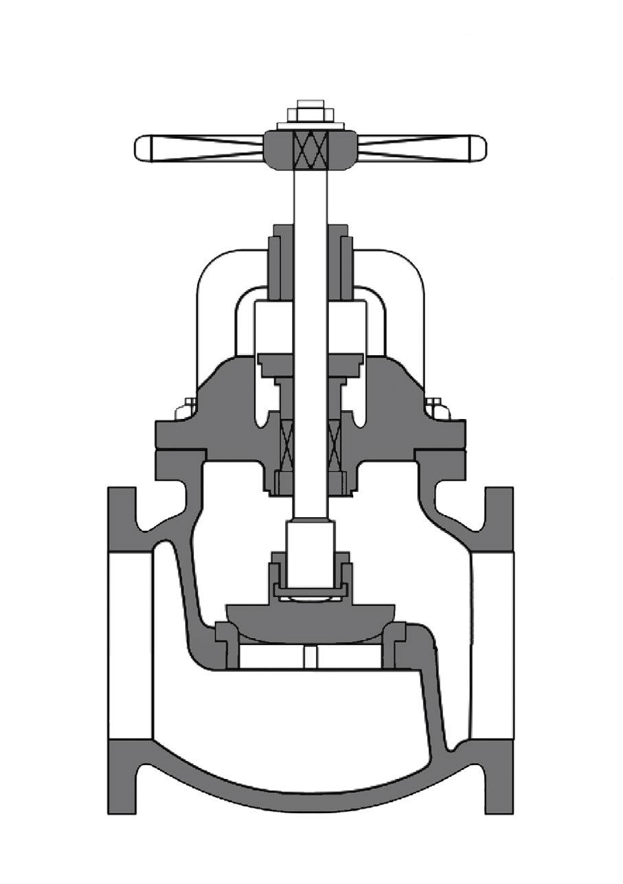
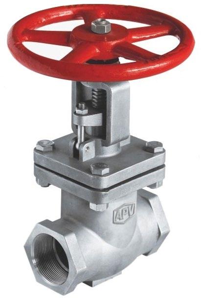
Design
ANSI B16.1, ANSI B16.42, MSS SP85, BSEN 13789 (BS 5152). Features Outside screw & yoke, bolted bonnet, rising stem/handwheel. Flanging/Pressure Class
ANSI B16.1 125lb, 150lb, 250lb AS 2129 ANSI B16.42 150lb, 250lb AS 2129 Table D, E, F, H AS 4087 PN10, PN14, PN16, PN21, PN35 AS 4331.1 PN10, PN16 EN 1092-2 PN10, PN16 ISO 7005-1, PN10, PN16 Face to Face Dimensions EN 558-1 Series 10, ASME B16.10, MSS SP85.
* For gear operator refer to drawing. Bronze or stainless steel stem and/or trim also available. Maximum temperature 210°C
D, Table E
Design ANSI B16.1 (CI), MSS SP85, BSEN 13789 (BS 5152), ANSI B16.42 (DI).
Features 2500 kPa CWP. Outside screw & yoke, bolted bonnet, rising stem/handwheel. Flanging/Pressure Class
EN 1092-2 PN25
ISO 7005-1 PN25 AS 2129 Table F AS 4087 PN21, PN35 (PN25 rated) AS 4331.1 PN25
Face to Face Dimensions EN 558-1 Series 21
Test Standard EN 12200-1, ISO 5208
For gear operator refer to drawing.
MATERIALS LIST
DIMENSIONS & WEIGHTS
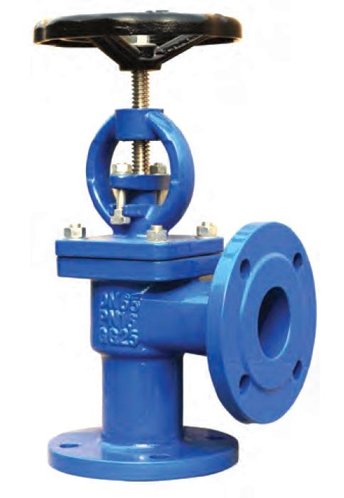
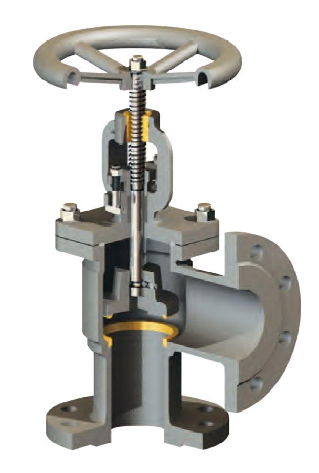
Features Bolted bonnet outside screw & yoke (clockwise closing direction.) Available as Standard Globe and Screw-Down Non-Return (combination globe and check valve), Swivel Disc - guided loose disc for combination check and stop.
Design
ANSI B16.1, MSS SP85, BSEN 13789 (BS 5152), ANSI B16.42.
Flanging/Pressure Class
ANSI B16.1 125lb, 150lb ANSI B16.42 150lb AS 2129 Table D, E, F, H AS 4087 PN14, PN16, PN21 AS 4331.1 PN10, PN16 EN 1092-2 PN10, PN16 ISO 7005-1 PN10, PN16 JIS B2220 5K, 10K, 16K, 20K
Face to Face Dimensions
BSEN 13789 (BS 5152), BS.558, ASME B16.10, MSS SP85.
* Design to ASME B16.34
* Investment Cast
* Large Flow Port
MATERIALS LIST
ANSI CLASS 150~600 •
DIMENSIONS & WEIGHTS
* Design to ASME B16.34
* Investment Cast
* Large port design
MATERIALS LIST
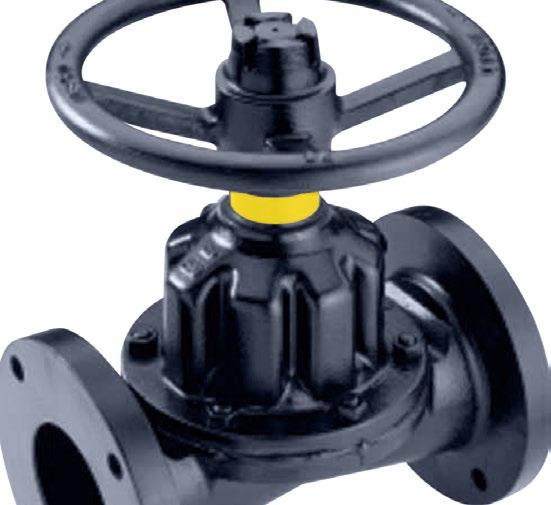
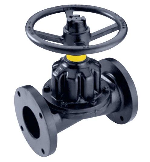
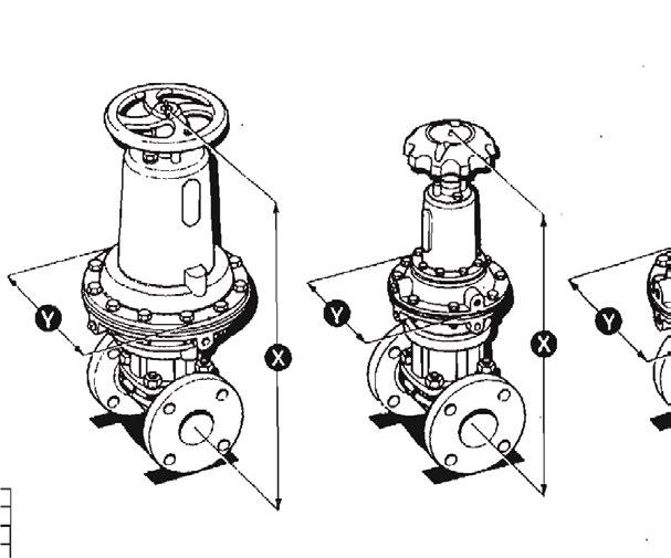
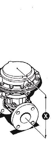
APA Weir Type Valve offers smooth flow & simple operation in any position. Parts interchange with the existing market leader of diaphragm valves and dimensions are the same. Its design provides extra-long diaphragm life for throttling and positive shut-off services. Hygienic style also available.
Size Range 8mm to 350mm.
Design
EN 13397 (BS 5156)
Temperature Range -45ºC to 171ºC.
Body Linings
Hard Rubber, Soft Rubber, Neoprene, Glass, Butyl, Ceramic, PFA, PP, ETFE, Polypropylene, Halar & PVDF
Diaphragms
Pressure Range to 1580 kPa.
Body Materials
Cast Iron, Ductile Iron, Bronze, Aluminium and Stainless Steel
Flangings
AS 2129 Table D/E/F ANSI 125 AS 4087 PN14/PN16 AS 4331.1 PN10/PN16.
Butyl, EPDM, Polyethylene, Polychloroprene.
Design Advantages
The body of which gives a smooth pocketless flow and features low pressure drop. Suitable for high line pressure duties and is available in a range of trims & materials for gases and liquids.

Bonnet Assembly
Contains a compressor which supports the diaphragm at all stages of travel
Diaphragm
Specially shaped to achieve leak tight seat against wall.
The catalogue is general in it’s nature and design and can vary at any time. This catalogue is to be used as a guide only.
APKB Straight Thru Valves efficiently handle abrasive and corrosive slurries, thick coagulating fluids, and a wide variety of suspended solid materials. Parts interchange with the existing market leader of diaphragm valves and dimensions are the same.
Size Range 15mm to 350mm.
Design
EN 13397 (BS 5156)
Temperature Range -40ºC to 121ºC.
Body Linings
Cast Iron, Hard Rubber, Soft Rubber, Neoprene, Glass Lined, Butyl, Ceramic, PFA, PP, ETFE, PVDF.
Diaphragms
Pressure Range
Vacuum to 690 kPa.
Body Materials
Cast Iron, Ductile Iron, Bronze, Aluminium and Stainless Steel
Flangings AS 2129 Table D/E/F ANSI 125 AS 4087 PN14/PN16 AS 4331.1 PN10/PN16.
Butyl, EPDM, Polyethylene, Polychloroprene.
Design Advantages
The body design offers minimum friction, no turbulence & is suitable for sludge and slurry pressure gases.

Bonnet Assembly
The compressor & spindle design gives a long travel sufficient to contact the valve body seat & to lift the diaphragm up into the bonnet to provide total clearance of the pipeline.
Diaphragm
Specially shaped to achieve leaktight seat against valve wall.
Body
Allows greater flow and is suitable for rodding through.
The catalogue is general in it’s nature and design and can vary at any time. This catalogue is to be used as a guide only.
DOUBLE ACTING ACTUATOR
• Body & Bonnet
Inside and outside epoxy powder coated for long life corrosion protection. Straight-through full bore to avoid debris trap and minimise flow resistance.
• Wedge
Ductile iron according to EN 1563. Wedge inside and outside fully rubberized with vulcanized EPDM or NBR, suitable for potable water with drain hole.
• Wedge Guide
Wear resistant plastic with high gliding features. Optimally placed design guarantees lowest wear and tear and lowest closing torques.
• Wedge Nut
Brass wedge nut with abundant over sizing of the required thread length in the wedge nut guarantees the highest possible breaking torques.
• Gasket
Rubber bonnet gasket for longevity and protection of bonnet bolts, Isolated fasteners for corrosion protection.
• Stem SS420 (X20Cr13), with rolling thread for high tensile strength and corrosion resistance
• Back Seal
Rubber back seal facility to rolling thread for high strength and corrosion resistance
• O Rings
Rubber O rings can be replaceable under full pressure.
• Wiper Ring
Wiper ring used to prevent impurities from entering the stem sealing system
• Operation Hand wheel, Square cap.
LIST (Generic Example)
• Style Inside screw & yoke, solid wedge disc, bolted bonnet, non rising stem.
• Design Standards AS 2638.2, MSS SP70 Type 1, AWWA C509-09, BSEN 1171/BS 5163.
• Flanging & Rating AS 2129 Table D, E, F AS 4087 PN14, PN21
AS 4331.1 PN10, PN16, PN25 EN 1098-2 PN10, PN16, PN25
ISO 7005-1 PN10, PN16, PN25
ASME B16.1 125 Class, 250 Class
• Face to Face Dimensions
AS 2638.2, BSEN 1171 (BS 5163), ANSI B16.10
Sewage Systems
Water Systems
Industrial Systems
Food and Beverage Systems
ASA125 1400 kPa (200 PSI) max cold working pressure. PN10 1000 kPa (145 PSI) max cold working pressure.
PN14 1400 kPa (203 PSI) max cold working pressure.
PN16 1600 kPa (232 PSI) max cold working pressure.
PN25 2500 kPa (362 PSI) max cold working pressure.
MATERIALS
DIMENSIONS & WEIGHTS
Design AS 2638.2
Features Bolted Bonnet Inside Screw Non Rising Stem Replaceable O-ring Low torque operation Rubber encapsulated wedge
Clockwise closing direction
Fusion bonded epoxy coated inside and outside
Maximum temperature 80°C
Suitable for waste, sewage & industrial
Flanging & Rating AS 2129 Table D, E AS 4087 PN14, PN16 AS 4331.1 PN10, PN16 EN 1092-2 PN10, PN16 ISO 7005-1 PN10, PN16 ASME B16.1 125 Class
Pressure Test & Torque Test AS 2638.2, ISO 5208
Options
Stem Cap, Position Indicator, ISO Top Flange, Extension Spindle / T Key.
MATERIALS
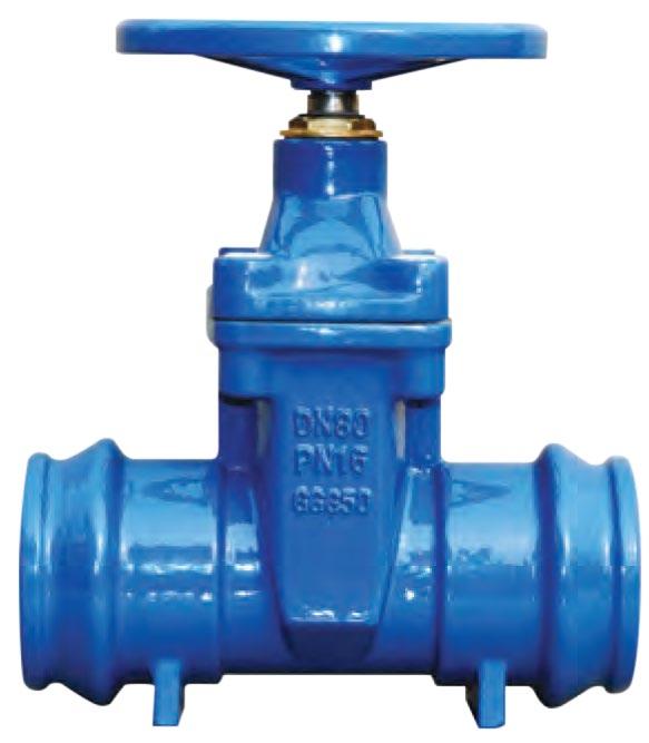
Design AS 2638.2
Features Bolted Bonnet Non Rising Stem Replaceable O-Ring Low torque operation
Rubber encapsulated wedge
Clockwise closing direction
IPS PVC Push-on
Fusion bonded epoxy coated inside and outside
Maximum temperature 80°C
Suitable for waste, sewage & industrial
Flanging & Rating AS 2129 Table D, E AS 4087 PN14, PN16 AS 4331.1 PN10, PN16 EN 1092-2 PN10, PN16
ISO 7005-1 PN10, PN16
Pressure Test & Torque Test AS 2638.2, ISO 5208
Options
Stem Cap, Position Indicator, Extension Spindle / T Key.
MATERIALS
DIMENSIONS
Design
BSEN 1171/BS 5163, BSEN 558-1 (Face to Face)
Features Non Rising Stem Clockwise Closing Replaceable O-Ring Low torque operation Rubber encapsulated wedge Fusion bonded epoxy coated inside and outside Maximum temperature 80°C
Flanging & Rating
AS 2129 Table D, E AS 4087 PN14, PN16 AS 4331.1 PN16
EN 1092-2 PN16
ISO 7005-1 PN16 ASME B16.1 125 Class
Pressure Test & Torque Test
ISO 5208, BSEN 12266-1, AS 2638.2
Options
Stem Cap, Position Indicator, ISO Top Flange, Extension Spindle / T Key.
MATERIALS
DIMENSIONS & WEIGHTS
Design BSEN 1171/BS 5163, BSEN 558-1 (Face to Face)
Features Non Rising Stem Clockwise Closing Replaceable O-Ring Low torque operation Rubber encapsulated wedge Fusion bonded epoxy coated inside and outside Maximum temperature 80°C
Flanging & Rating AS 2129 Table D, E AS 4087 PN14, PN16 AS 4331.1 PN10, PN16 EN 1092-2 PN10, PN16 ISO 7005-1 PN10, PN16
Pressure Test & Torque Test ISO 5208, BSEN 12266-1, AS 2638.2
Options Stem Cap, Position Indicator, ISO Top Flange, Extension Spindle / T Key, Gear Box, By-Pass Valve.
Design BSEN 1171/BS 5163, BSEN 558-1 (Face to Face)
Features Non Rising Stem Clockwise Closing Replaceable O-Ring Low torque operation Rubber encapsulated wedge Fusion bonded epoxy coated inside and outside Maximum temperature 80°C
Flanging & Rating
AS 4331.1 PN25 EN 1092-2 PN25
ISO 7005-1 PN25 AS 2129 Table F AS 4087 PN21, PN35 (PN25 rated) ASME B16.42 150 Class
Pressure Test & Torque Test AS 2038.2, ISO 5208, BSEN 12266-1
Options
Stem Cap, Position Indicator, ISO Top Flange, Extension Spindle / T Key, Gear Operator (350NB & over).
DIMENSIONS & WEIGHTS
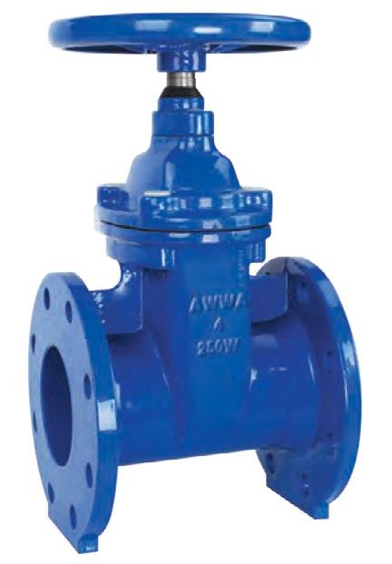
Design AWWA C509-09 MSS SP70-1
Features
Replaceable O-Ring
Low torque operation
Rubber encapsulated wedge
Clockwise closing direction Fusion bonded epoxy coated inside and outside Temperature 33~125°F/0.6~52°C
Technical Specification
Face to Face ANSI B16.10
Flanges Drilling ANSI B16.1
Class 125/Class 150
Work
(1378KPA) 200 PSI
Design AWWA C509-09 MSS
Features Ductile Iron Body Non Rising Stem direction Clockwise closing
Replaceable O-Ring
Low torque operation
Rubber encapsulated wedge
Fusion bonded epoxy coated inside and outside
Maximum temperature 80°C
Technical Specification Face to Face ANSI B16.10
Flanges ASME B16.42 150LB
Also available drilled AS 2129 Table F, AS 4087 PN21
Hydraulic test to:
Seat Test Pressure 275 PSI
Shell Test Pressure 375 PSI
Operating torque test
Options
Stem Cap, Position Indicator, ISO Top Flange, Extension Spindle / T Key
MATERIALS LIST PN16*
DIMENSIONS & WEIGHTS PN16*
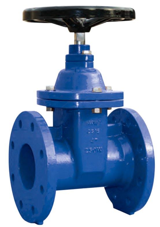
Design
BSEN 1171 / BS5163
BSEN 558-1 (Face to Face)
Features Rising Stem Bolted Bonnet
Outside stem and yoke (OS&Y) Low torque operation
Rubber encapsulated wedge
Clockwise closing direction
Fusion bonded epoxy coated inside and outside
Maximum temperature 80°C
Flanging & Rating
AS 2129 Table E, F AS 4087 PN14, PN16, PN21, PN35 (Rated PN25) AS 4331.1 PN16, PN25
EN 1092-2 PN16, PN25
ISO 7005-1 PN16, PN25
ASME B16.1 125 Class, 150 Class
Pressure Test
ISO 5208, BSEN 12266-1, AS 2638.2
Operating Torque Test Performed
*PN25 refer to drawing.
MATERIALS LIST
5 Bonnet Gasket
DIMENSIONS & WEIGHTS
Design
AWWA C509-09
MSS SP70-1
Features
Ductile Iron Body
Outside stem and yoke (OS&Y)
Bolted Bonnet
Low torque operation
Rubber encapsulated wedge
Clockwise closing direction
Fusion bonded epoxy coated
Inside and outside
Maximum temperature 80°C
Technical Specification
Face to Face: ANSI B16.10
Flanges: ASME B 16.42 150LB
Also available drilled:
AS 2129 Table F
AS 4087 PN21
AS 4331.1 PN16
ISO 7005-1 PN16
Hydraulic test to AWWA C509/API 598
Seat Test Pressure: 275PSI
Shell Test Pressure: 375PSI
Operating torque test
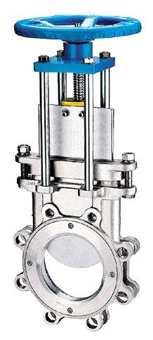
PULP - CHEMICAL - PAPER - CHEMICAL - PETROLEUM PROCESS - POWER - SEWERAGE - MINING
Available to suit - ANSI 125LB, 150LB, 300LB, AS 4087/AS 4331.1/EN 1092/ISO 7005-1 PN6~16 and AS 2129 Table D to F
Design: AS 6401, MSS 5081
DESIGN FEATURES (All types)
BODY
• Low Maintenance
GATE
• Flat edge on resilient seated valves and bevelled edge on metal seated valves.
METAL SEAT DESIGN
• Fully in field replaceable seat insert
• Bi-directional flow
• Heavy bevelled gate cuts through solids and slurries and cleans as it closes.
• Line pressure further assists sealing of gate and seal.
PTFE SEAT DESIGN
• Fully in field replaceable seat insert.
• Uni directional flow.
• Drip tight shut off available.
RESILIENT SEAT DESIGN
• Fully in field replaceable seat insert.
• Bi directional flow.
• Drip tight shut off in preferred direction.
• Bi-directional flow, Viton, EDDM, NBR and EPDM available.
• Sealing is affected between the gate and seat, no pressure required for shut-off to occur.
• Positively retained seat does not allow the seat to pull out or move within the body.
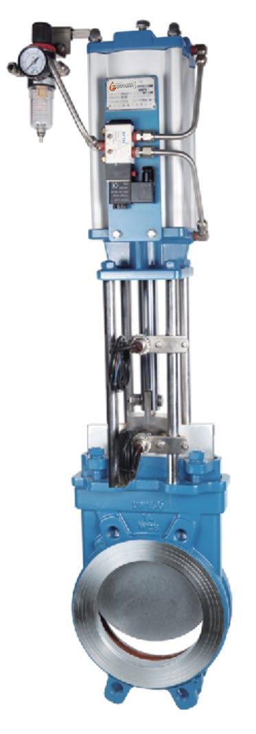
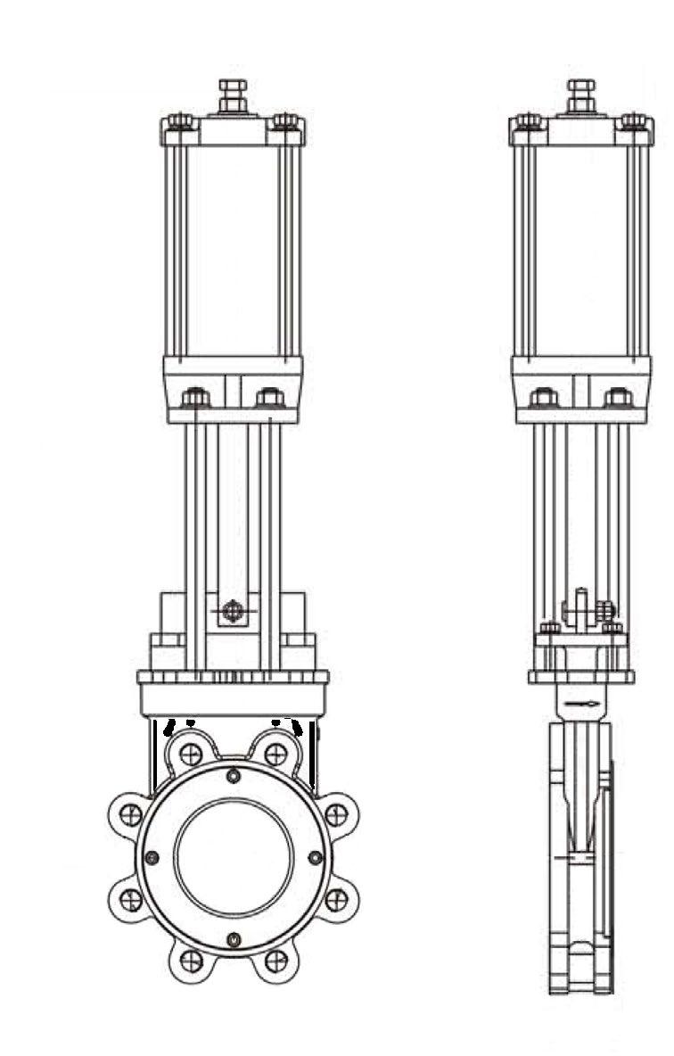
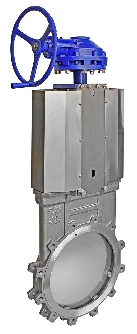
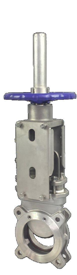
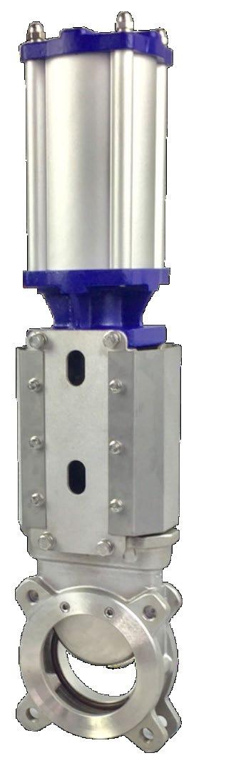
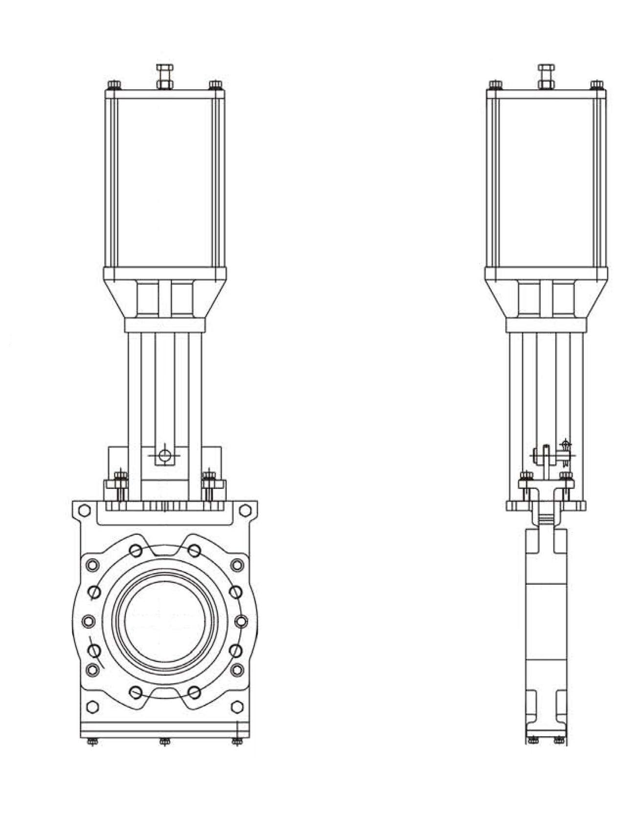
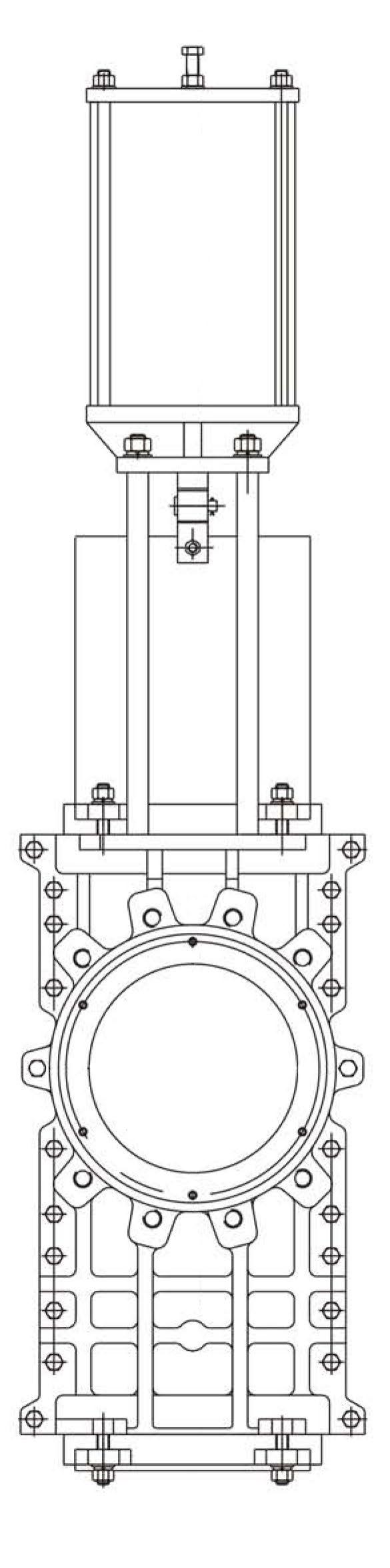
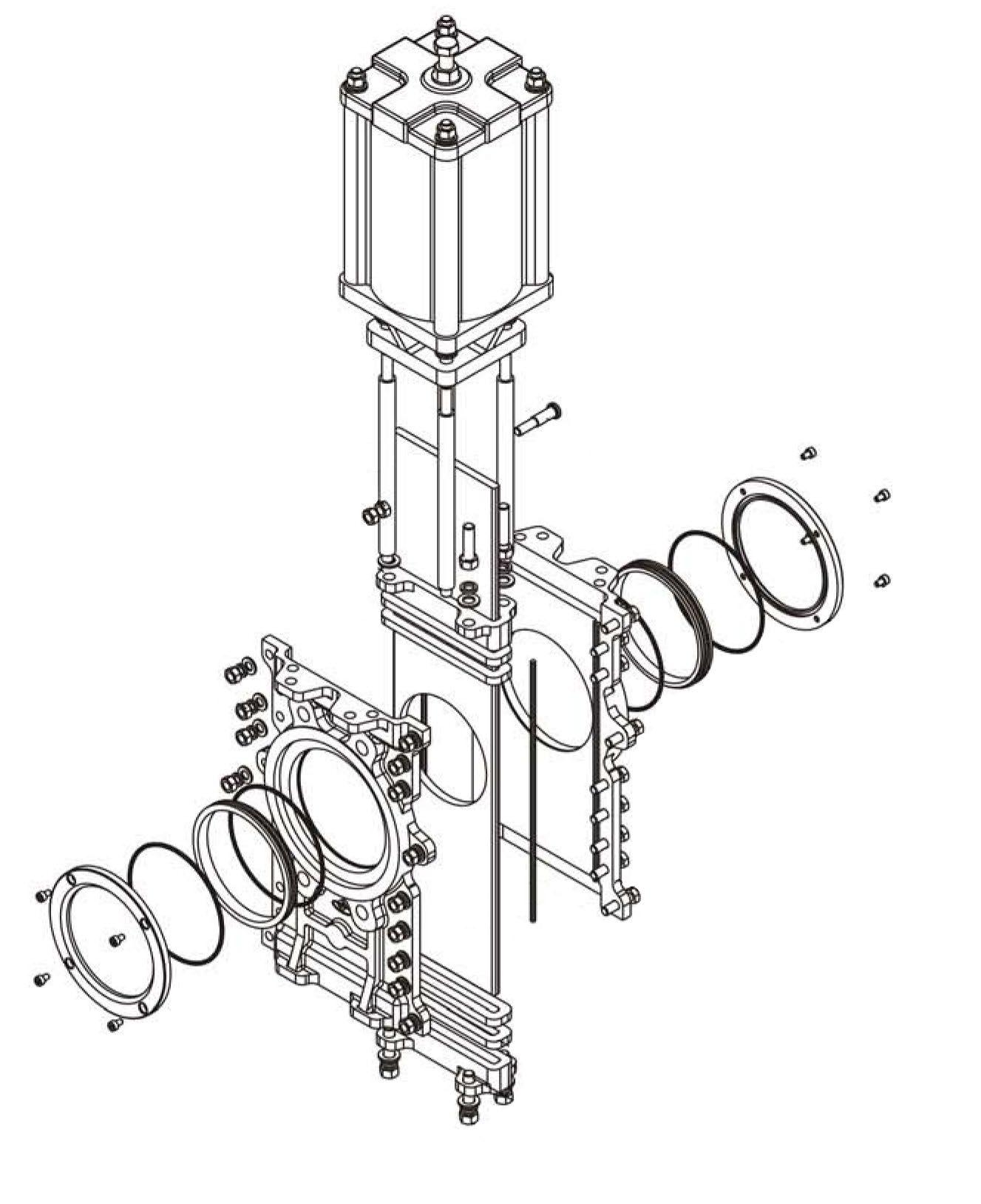
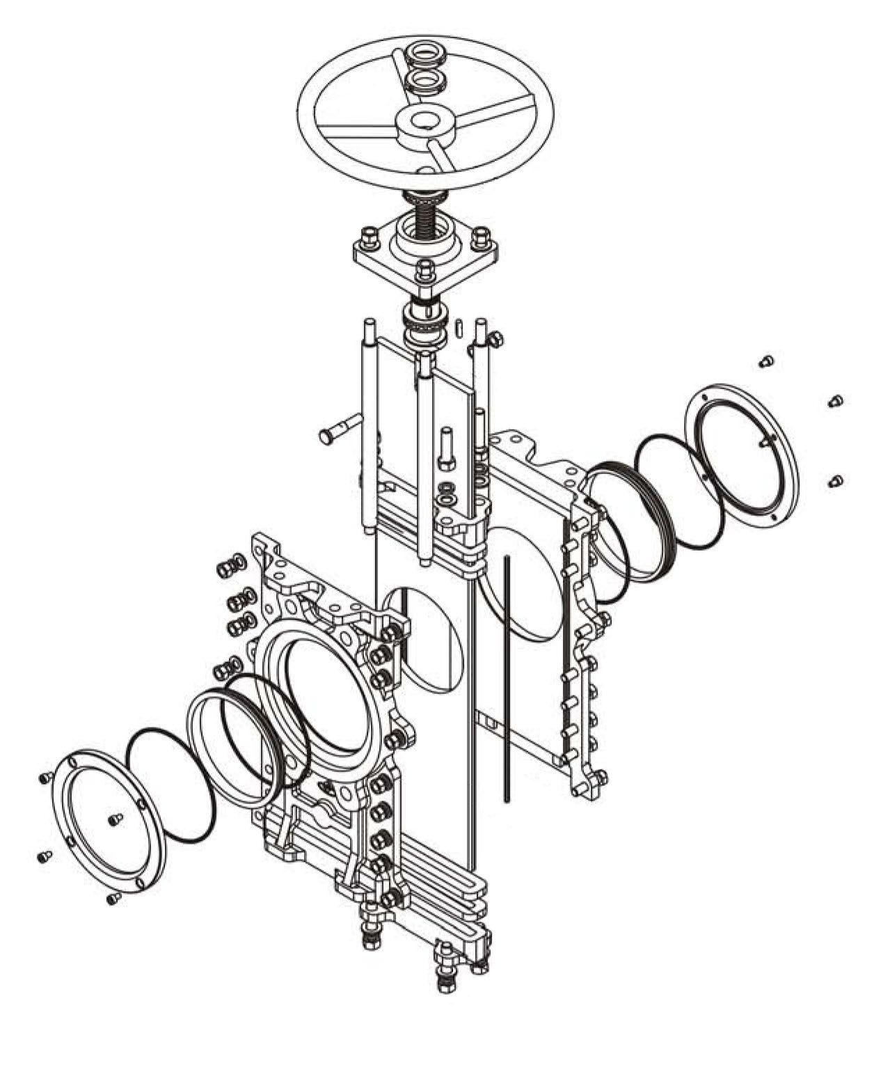
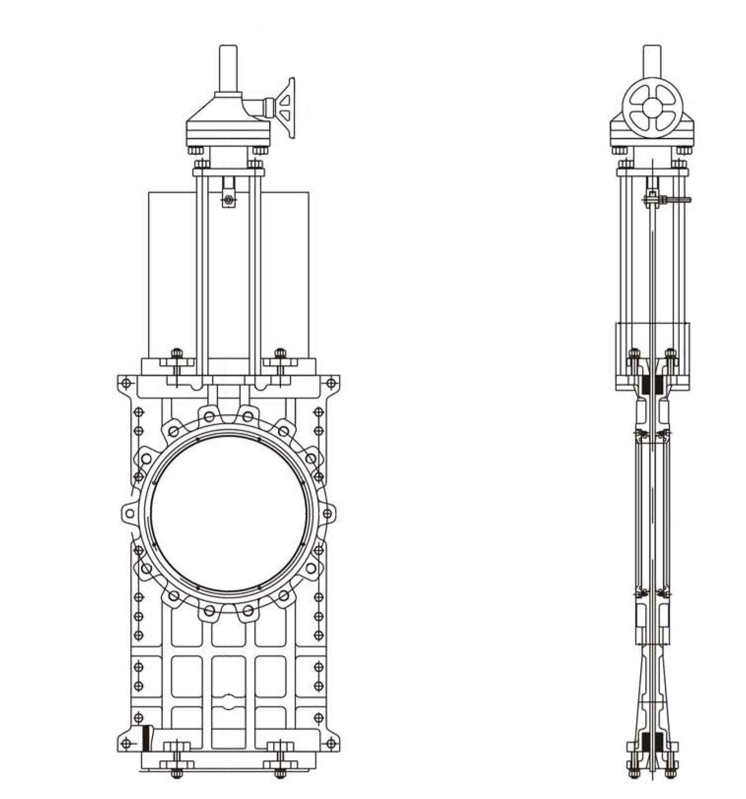
SERVICE
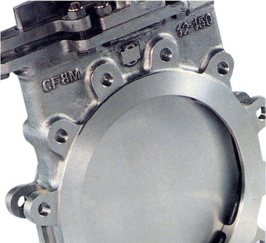
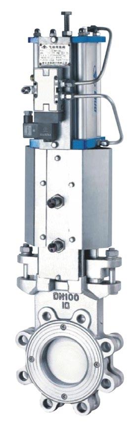
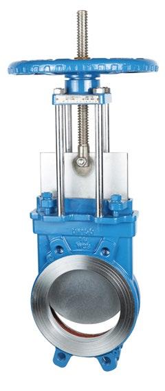
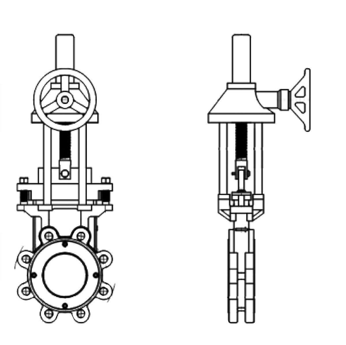
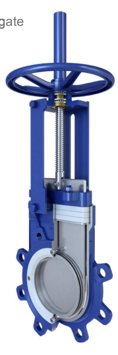
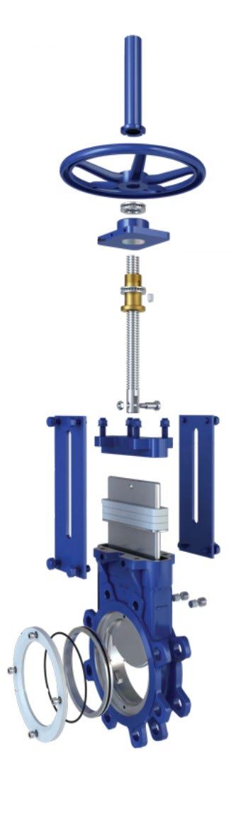
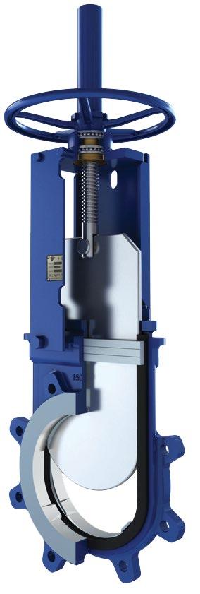
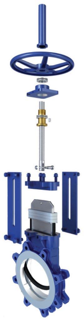
ADC Series knifegate valves are linear shut off valves. These compact valves are available as manual with handwheel, or can be automated with a pneumatic cylinder actuator for remote operation. ADC Series valves are ideal for many applications in process industries including Pulp & Paper, Wastewater Treatment, Mining, Sugar Making and Chemical Processing.
Seats in the ADC Series knife gate valves are backed with an o-ring to give the seat a self-compensating wear function. This results in excellent seat tightness and prolonged life cycle. When seats do wear and need replacement, maintenance to change the seats is easy and quick. Available seat materials include metal seated, EPDM seated and PTFE seated.
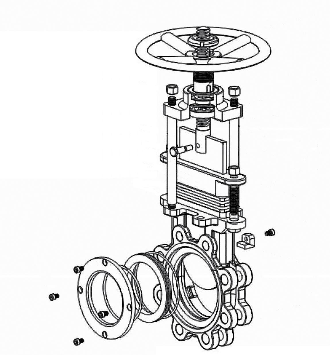
GATE DESIGN
Each gate is precision ground and hard Chrome plated as a standard. This provides superior abrasion and corrosion resistance. The arc shape design of the bottom of the gate is particularly suitable to provide strong cutting force for pulp and suspended particulates in media.
Guiding wedges are point-located at the valve outlet, providing for a groove-free and smooth port. This reduces clogging or material build-up.
Packing gland and packing are externally located, so packing can be adjusted or replaced without removing the valve from the pipeline.
At the top of the yoke, our knife gate valves are equipped with two stem bearings for reduced torque and easy operation.
Custom port shapes including V-port, triangle port and hexagon port are available.
Also full through conduit ‘O’ Port design is available.
Nominal Diameter 2” (DN50) through 48” (DN1200)
Flanging/Rating ANSI 125/150/300, AS 4087/AS 4331.1/EN 1092/ISO 7005-1 PN 6~35 and AS 2129 Table D to H.
Connection Type Wafer pattern fully lugged.
Temperature Metal Seat -20ºC to 230ºC, PTFE Seat -20ºC to 200ºC, EPDM Seat -20ºC to 120ºC, Viton Seat -20ºC to 200ºC, NBR Seat -20ºC to 900ºC
Applicable Medium Pulp, sewage, coal slurry, syrup, slag.
Leakage EPDM & NBR seat valves are leak tight in the preferred direction. As per MSS SP-61, AS 6401 standard. The maximum allowable leakage of metal seated knife gate valves is 40 ml/min/inch. For PTFE seated knife gate valves, tight shut off in lower pressures with a maximum leakage of 4 ml/min/inch. Elastomer seated are all drip tight shut off in the preferred direction.
Precison Machined and Fitted seat and gate/body contact Precision machining tolerances ensure long life and leak tight seat and gate/body contact. Extra sealing ensured by an o-ring fitted to the side of the seat.
SEAT CONSTRUCTION

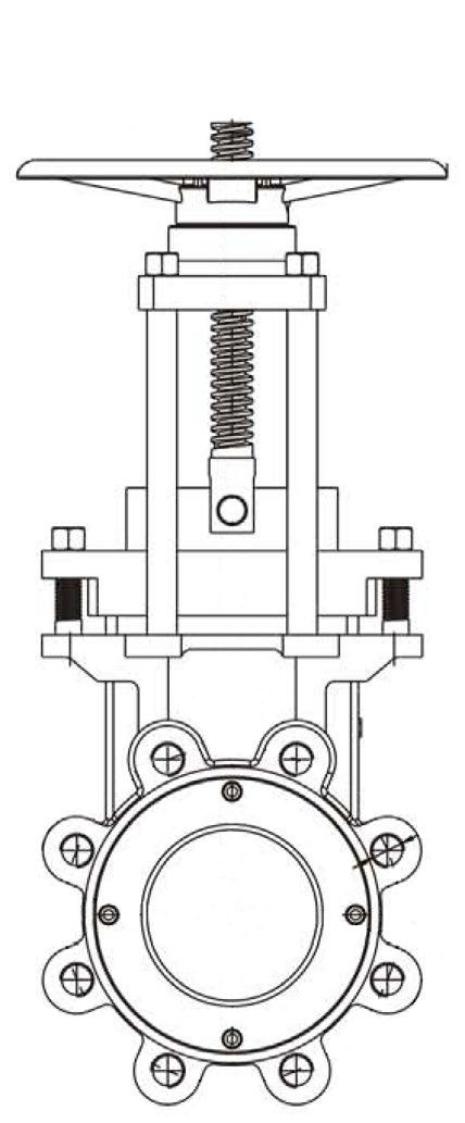
DIMENSIONS ADC SERIES (HANDWHEEL OPERATED) (MM)
Example only. Refer to as built drawing.
The catalogue is general in it’s nature and design and can vary at any time. This catalogue is to be used as a guide only.
DIMENSIONS ADC SERIES (GEAR OPERATED) (MM)
The catalogue is general in it’s nature and design and can vary at any time. This catalogue is to be used as a guide only. For DCNP Series see other table. This is a ready reckoner guide only. Data varies according to model variation.
Following is general information and materials required for special application should be specified.
* Cold only, not hot. **High impact resistant.
Note: Ø Excellent, o Good, ∆ Fair, X Poor
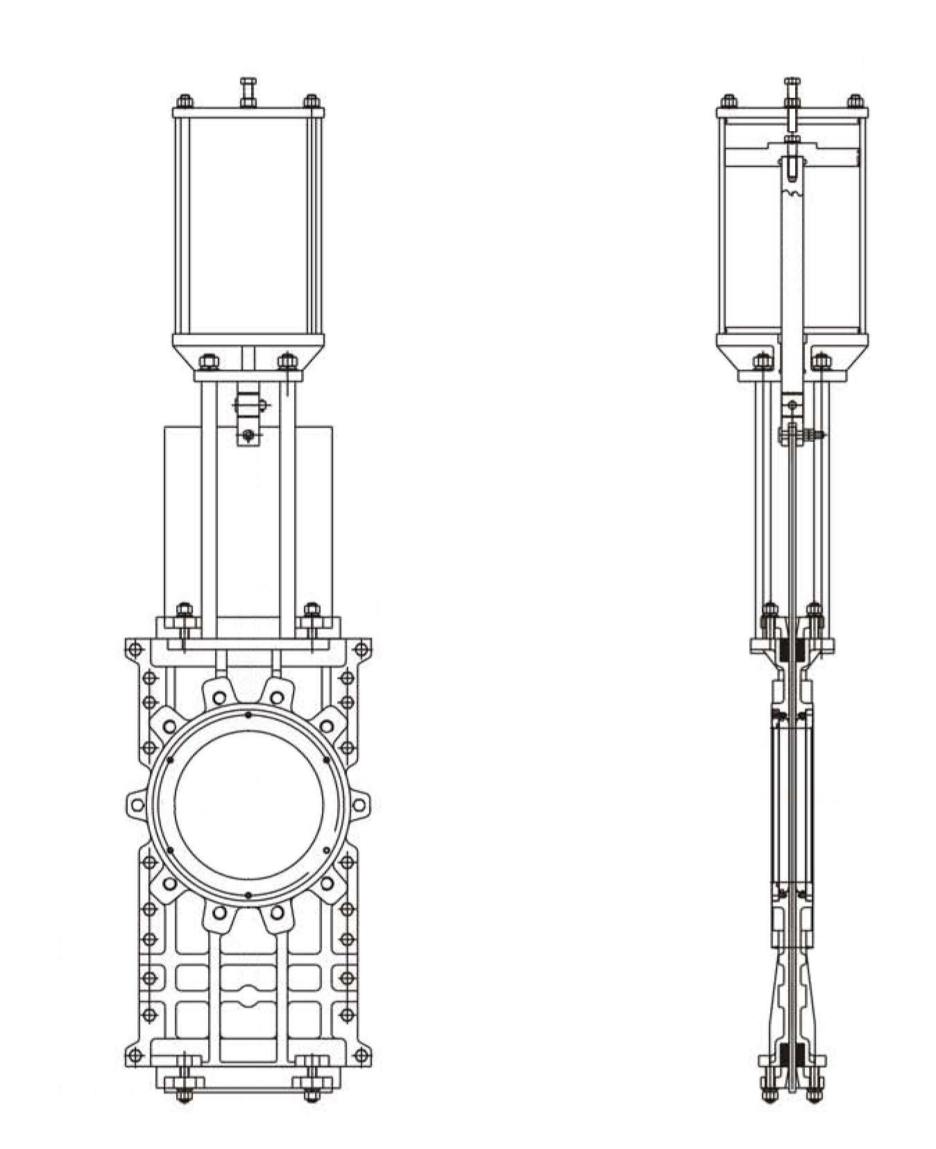
SIZING INFORMATION FOR HEAVY DUTY AIR CYLINDER OPERATOR ADC SERIES
Cylinders for air, oil and water for Knife Gate Valves with line
of
kPa. This is a rough estimating guide.
“R” indicates resilient-seated valve
“M” indicates metal-seated valve
“O” indicates one side resilient-seated valve
This is a “ready reckoner” for ‘ADC’ series - but is a guide only. Cylinder size varies depending on model*, pressure, seat type, configuration and media.
For slurry service next size up is required, please consult us. Special slurry design valve required.
The catalogue is general in it’s nature and design and can vary at any time. This catalogue is to be used as a guide only.
DESIGN
Flanging
ANSI B16.1/B16.5 125lb/150lb AS 2129 Table D, E AS 4087 PN14, PN16 ISO 7005-1, PN10, PN16 AS 4331.1 PN10, PN16 EN 1092-2 PN10, PN16
Pressure/Class
Rating
PN10 Rated Body.
Long Term Maximum
Packing & Seat Rating:
10 bar to 250NB
7 bar 300 ~ 450NB
4 bar 500 ~ 600NB
Face to Face Dimensions AS 640I & MSS SP-81
Test Standards
MSS-SP71, ISO 5208, MSS SP-SP61
Pressure/Temperature
Rating Seat
NBR 10 bar -10 to 90ºC
EPDM 10 bar -10 to 120ºC
Viton 10 bar -10 to 200ºC
PTFE 10 bar -10 to 200ºC
Metal to Metal 10 bar -10 to 200ºC
Epoxy Coated
Stainless Steel Tie Rods Aluminium Case
Slots to Facilitate Limit Switches Stainless Steel Support Plate Stainless Steel Fixtures Optional Stainless Steel Housing
Adjustable solid tipped PTFE Gate Scraper Guides for tight shut off Hard Chrome Plated Gate for Longer Life
Optional Stainless Steel Safety Guards (Manual & Actuated Versions)
Resilient seated uni-directional valves are tested leak tight up to 4 Bar (Elastomer) and 2.8 Bar (PTFE) on seat. The Flowturn DCNP is one of the only Knife Gate designs in the world offering a rugged and flexible PTFE seated valve with a tight shut-off. Above 4 Bar these pressures seat leakage rate is estimated at up to 2.66 drops/minute/inch (0.11 drips/minute/DN) as per MSS-SP61. However an actual seat test can be performed above 4.0 Bar if required. Special packing systems and bonnet designs are available for high pressure applications.
Flow direction is from the oposite side of the valve for the seat This provides superior shut-off by pressure energising the gate against the seat and also protects the seat.
STANDARD DESIGN FEATURES
Bevelled edge uni-directional wafer style, fully lugged, rising stem full flow integral body knife gate offering tight shut off (resilient seat) clockwise close on-off operation. The DCNP Model has solid PTFE faced energised adjustable gate pressure scraper blocks, multi row composite packing system and double row stem bearings. Stainless steel safety guards and stem protector are also available.
• Cast-in gate guide claws ensure a tight enegised seal and eliminates potential valve shut-off clogging while avoiding seat damage.
• Unique multi row packing system comprises braided PTFE/silicon/PTFE-sheet to form a composite sealing system ensuring drip tight shut off for different media/temperature and pressure applications.
• Adjustable solid PTFE tipped stainless steel gate scraper guides minimise the chance of leakage over a longer period and eliminates metal-metal contact between gate and body.
• Bevelled knife edge provides strong cutting stress and tight sealing.
• Gate surface is polished and hard chrome plated both sides.
• Precision machined side-entry seat is replaceable, reducing the cost of maintenance. Additional seat retainer o-ring on PTFE and metal seat version prevents leakage.
• L-shape replaceable seat retainer locks seat into valve body and protects seat side from media.
OTHER FEATURES
• Stainless steel safety guards (optional).
• Stainless steel stem cover tube.
• Two roller thrust bearings minimises torque for operation.
• Grease nipple to ease bearing lubrication (optional).
• Stainless steel bearing housing (optional).
APPLICATIONS
Dependant on Body/Seat/Configuration - Pulp and Paper/Mining/Waste Water Treatment/Chemical Plants/Power Plants/Steel Industry/Aquaculture/Sewerage/Coal/Slurry/Syrup/Slag (not recommended for Air/Gas).
OPTIONS
• V shape / Triangle port.
• Bi-directional.
• Special alloys.
• Non-rising stem.
• Limit switches.
• Anti-clockwise close.
• Extensions.
Materials List Manual Operated
Materials List Manual Operated
8 Pin SS304 9 Gland CF8M/CF8/WCB+FBE 3
8 Pin SS304
9 Gland CF8M/CF8/WCB+FBE
AS2129 Table D/AS4087 CL14/16
AS2129 Table D/AS4087 CL14/16
DESIGN
Flanging
ANSI B16.1/B16.5 125lb/150lb AS 2129 Table D, E AS 4087 PN14, PN16
ISO 7005-1, PN10, PN16 AS 4331.1 PN10, PN16 EN 1092-2 PN10, PN16
Pressure/Class
Rating
PN10 Rated Body.
Long Term Maximum Packing & Seat Rating10 bar to 250NB
7 bar 300 ~ 450NB
4 bar 500 ~ 600NB
Face to Face Dimensions AS 640I & MSS SP-81
Test Standards
MSS-SP71, ISO 5208, MSS SP-SP61
Pressure/Temperature
Rating Seat
EPDM 10 bar -10 to 120ºC
Viton 10 bar -10 to 200ºC
Stem Cover
Double Row Thrust Bearings
Stainless Steel Bearing Housing & Grease Nipple
Stainless Steel Safety Guards
Slots to Facilitate Limit Switches Support Plate
Integral Body
Hard Chrome Plated Stainless Steel Gate for Longer Life
REPLACEABLE SEATS
Encapsulated Bi-directional seats ensure water tight shut-off in both directions. When seats do wear and need replacement, replacing the seat is easy.
GATE DESIGN
Each gate is precision ground and hard chrome plated as a standard. This provides superior abrasion and corrosion resistance. The edges are polished flat.
GUIDING GUIDES
Gate guides at the valve inlet and outlet (top & bottom) ensure alignment of gate throughout it’s travel.
DOUBLE STEM BEARINGS (Handwheel operated only)
At the top of the yoke, our knife gate valves are equipped with two stem bearings in a stainless steel housing and a grease nipple for reduced torque and easy operation.
PACKING
Proprietary multi-layer composite packing system ensures tight shut-off across a wide temperature range. Packing is fully adjustable and for non-hazardous service can be replaced without removing valve from line provided the line has been isolated and the valve is not under pressure. For air or gas applications, some packing leakage will occur, especially at higher pressures.
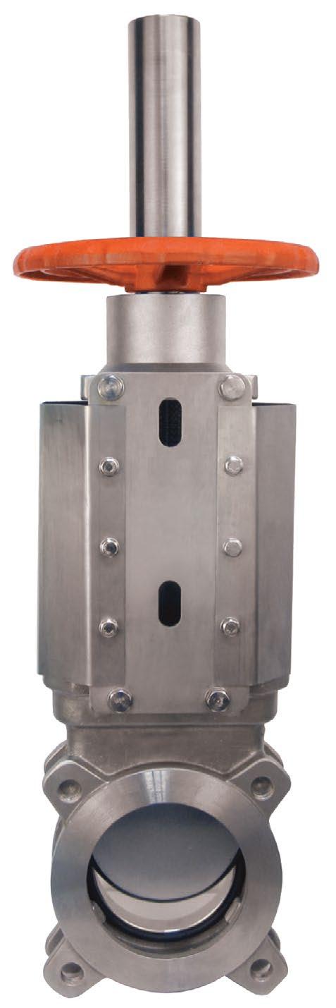
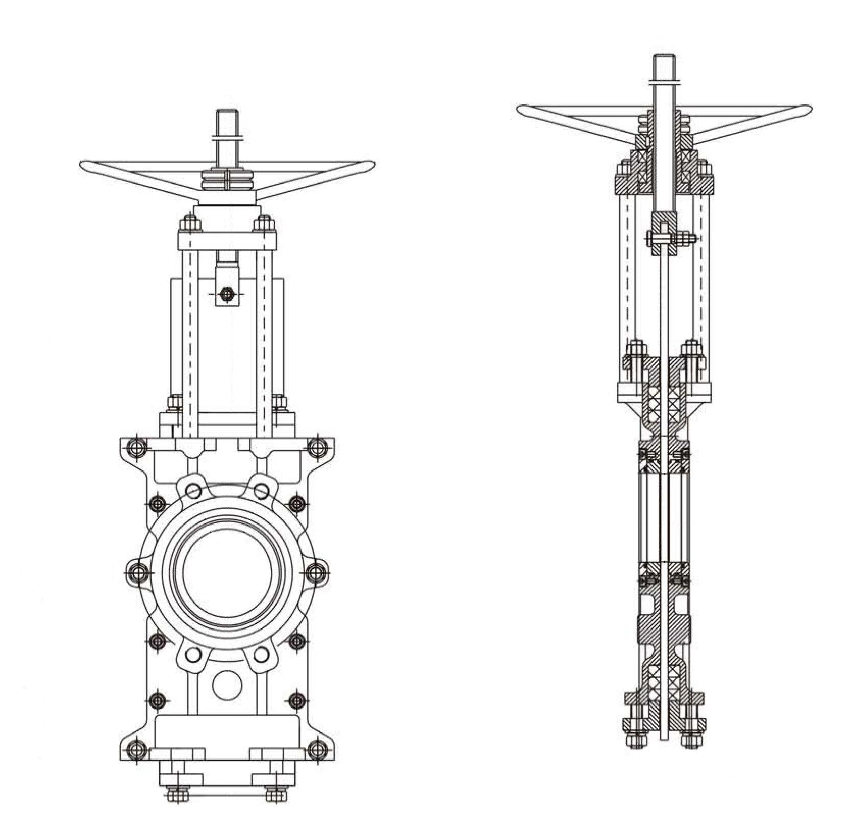
DCNP-B SERIES
Bi-directional wafer style, fully lugged, rising stem full flow integral body knife gate offering true bi-directional tight shut off (resilient seat) clockwise close on-off operation. The DCNP-B model has multi row composite packing system and double row stem bearings (handwheel operated only). Stainless steel safety guards and stem protector are also included. Suitable for pulp, sludge, water, chemicals, bio-mass, slurry, bio-gas (not air tight). The gate is fully guided in the body throughout its entire travel to provide true bi-directional service.
• Mono block integral body for extra strength and leak tightness.
• Cast-in gate guide claws (top & bottom) ensure a tight energised seal and eliminates potential valve shut-off clogging while avoiding seat damage.
• Unique multi row packing system comprises braided PTFE/silicon/PTFE-sheet to form a composite sealing system ensuring drip tight shut-off for different media/temperature and pressure applications.
• Suitable for dead-end service.
• Fully lugged design provides improved body strength & rigidity.
• Integral body ensures no shell leakage.
• Full port design minimises pressure drop and maximises flow capacity.
• Gate surface is polished and hard chrome plated both sides.
• Polished flat both faces and edges all around seating surface. The machining of the body inside, allows for more control in the different dimensions tolerances. This machining results in a perfect adjustment of the body with the gate and seal, reducing the required torque to maintain the tightness and avoiding any build-up of solids that could prevent the valve from closing. The valve design allows an end-of-line installation. Full port design in all cases for greater flow capacity and minimal pressure drop. The gate is guided on the whole stroke to ensure bi-directional shutoff.
• Precision design side-entry seat is replaceable, reducing the cost of maintenance.
• Replaceable seat is encapsulated into the integral valve body and ensures bi-directional flow.
• For air or gas applications leakage will occur especially at higher pressures.
• Seat is encapsulated into the body in contact with the gate all over its perimeter. This layout provides an adequate water tightness and seamless liquid flow in both directions. The seat is protected by the body itself.
• Stainless steel safety guards
• Stainless steel stem cover tube
• Grease nipple to ease bearing lubrication
• Two roller thrust bearings minimises torque for operation. with stainless steel bearing housing (handwheel operated only).
APPLICATIONS
Dependant on Body/Seat/Configurations - Sludge, Storm Tanks/Mining/Waste Water Treatment/Chemical Plants/Power Plants/Steel Industry/Aquaculture/Sewerage/Syrup/Sugar Manufacturing and Chemical Processing and bio gas (not air tight shut-off). Industry/ Aquaculture/Sewerage/Coal/Slurry/Syrup/Slag/Sugar Manufacturing and Chemical Processing (not recommended for Air/Gas).
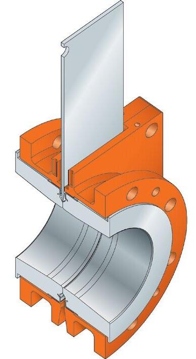
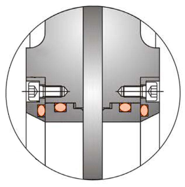
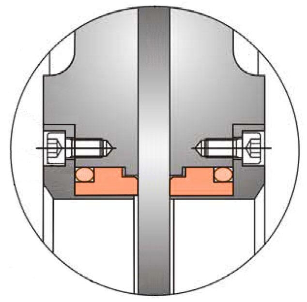
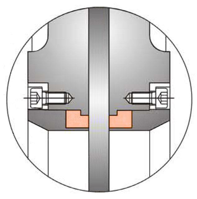
CLOSE UP VIEW SEAT
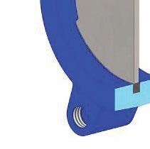
(1) Fusion bonded epoxy (2) Hard chromed both sides. Flat polished edge (3) Replaceable seat, full port (4) C/w grease fitting (5) Integral design ensures no shell leakage (6) Equivalent ISO 1083/JS/400-15/S, AS 1831-400-15, EN 1563 EN-GJS-40015
DIMENSIONS & WEIGHTS AS2129 Table D*/AS4087 CL14/16 (MM & KG)
Handwheel Operated
Gear Operated
Often, knife gate valve applications have suspended matter that can build up in the chest and pocket cavities. Severe build up can interfere with the normal operation of the valve. Purge ports can keep this build up from happening by flushing the valve with liquid, gas, or in some cases, steam. Purge ports are typically placed on the sides of the valve chest and bottom of the valve.
To enhance protection of the valve packing and maintain packing seal, a Teflon® or metal gate scraper can be installed in the base of the packing well. The gate scraper can clear abrasive and sticky material from the blade as the valve opens, minimizing wear to the packing.
In high abrasion applications, the valve seat and blade take the most abuse. For these services, Flowturn can supply hardened blades and/or metal seats to prolong the service life of these parts.
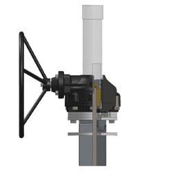
For remote mounted knife gate valve operators, Flowturn can supply stem extensions, floor mount pedestals, and stem guides. Stem extensions can be made in kit form for easy installation and can include stem guides and universal joints, depending on application requirements. Pedestals can be fabricated to specific mounting patterns for floor and direct actuator mounting.
In abrasive services, deflection cones can be mounted between the upstream valve flange and the adjoining piping. Though reducing the port area slightly, they can increase the life of the seat and gate and are less expensive to replace than the entire valve. Deflection cones are available in Ni-Hard and HDPE materials.
Sleeved Slurry Version - SDF
Bonneted Style c/w Drains/Purge - HSV
Deflector Cone Option
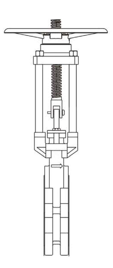
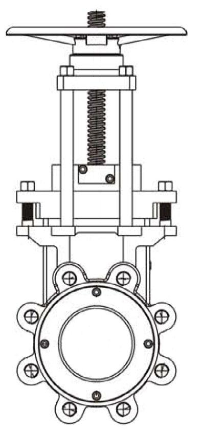
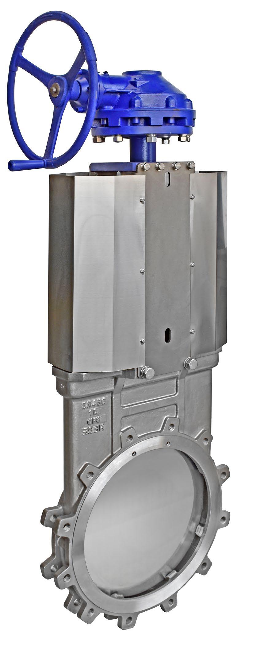
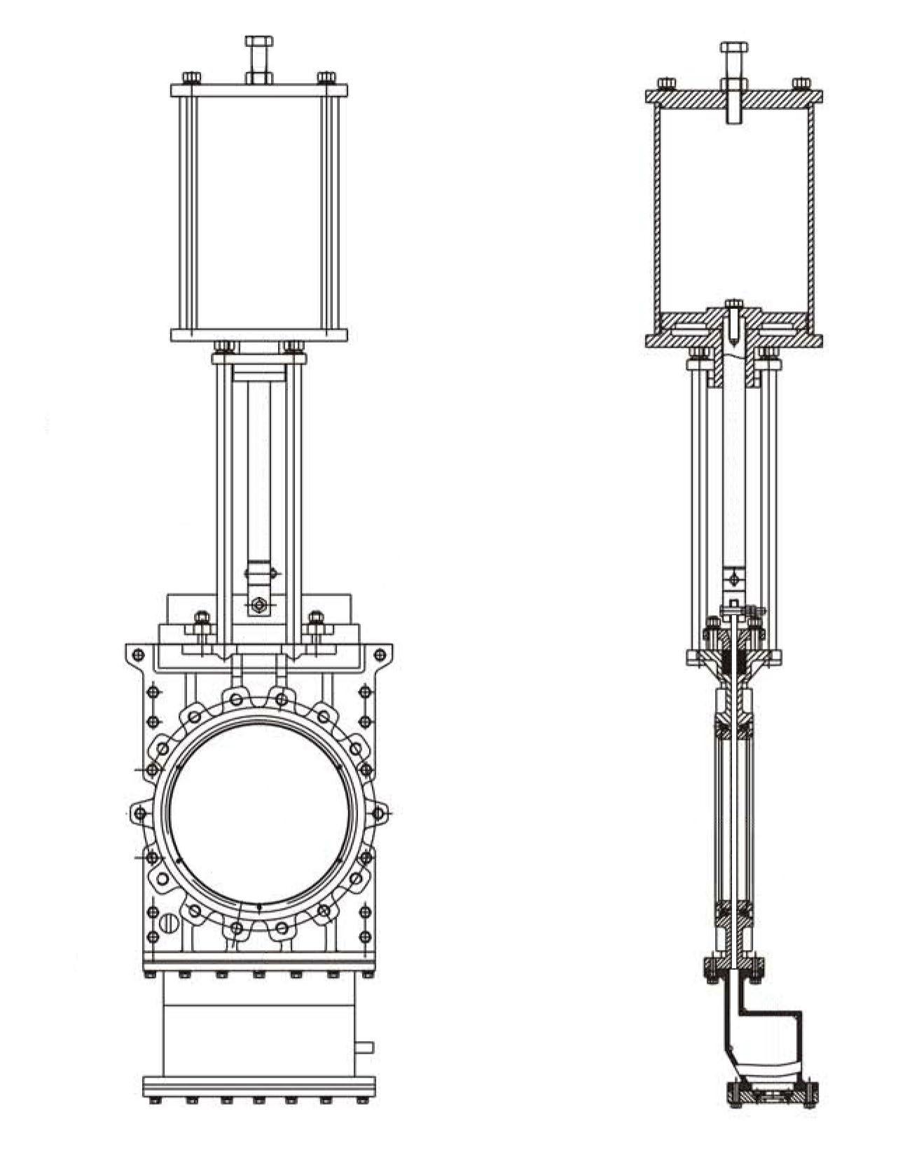
DK series knife gate valves are soft sealing linear shut off valves that are light weight with compact construction & convenient to install and use. Valves are full port in design to realise the characteristic of low flow resistance. Valves are available as manual with handwheel, or can be automated with an actuator for remote operation. The cone-shape design of the gate provides strong cutting force. The die-cast rubber seat is designed for bi-directional sealing. This design of valve ensures that when they are fully open, the medium will not ingress into the valve chest, which can prevent the valve chest from settling pulp during the valve running online, thus reducing maintenance cost.
DESIGN FEATURES
Gate
The arc shape design of the gate provides strong cutting force. Each gate is precision ground and hard chrome plated as standard. It provides superior abrasion and corrosion resistance.
Packing gland and packing are internally located, which ensures stable sealing and easy online maintenance.
Body is two piece design that is light weight and compact. The body is designed without any cavities, so there is no place for solids to accumulate. With this design, even with high solids content in the slurry, the valve will not jam.
The resilient and abrasion resistant rubber seat is die cast in a unique rubber mould and has a metal support ring to extend the life of the seat and valves. Seat material options are NBR, EPDM and natural rubber
The bottom discharge cover can easily be removed for routine cleaning. Flowturn can also fit the valve with a purge system.
1. Nominal Diameter: DN50-DN600
2. Flange connection as per: ANSI B16.5 125/150lb and AS 4087/AS 4331.1/EN 1092/ISO 7005-1 PN6~25 and AS 2129 Table D to F.
3. Valve design and manufacture as per: MSS SP-81
4. Material standard: ASTM A351, A216, etc.
5. Seat tightness testing pressure: 2.8 Bar and maximum allowable working differential pressure (10.3 bar for size ≤ DN600 / 24”, 6.9 bar for size > DN600/24”)
6. Air supply pressure: 4~7 bar
7. Connection Type: Lugged
8. Working Temperature: NBR: -20~+120°C; EPDM: -20~+120°C; Viton: -20~+200°C
9. Applicable Media: Pulp, Slurry, Water
10. Leakage: Zero Leakage
The design ensures low flow resistance at full open position as both seats maintain a continuous tight contact to form a full bore flow path due to the seat design with internal metal support.
The DK series offers perfect sealing performance to prevent the media clogging inside the body cavity, extending service life and reducing maintenance cost.
Both seats are in tight contact with the gate in all positions throughout opening and closing of the internal metal support ring as well as pipeline pressure to ensure absolute bidirectional bubble tightness.
Applications
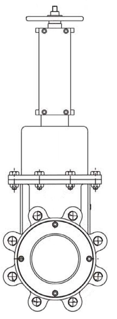
DT series knife gate valves are mainly intended for process control in pulp slurry, residue discharge and sewage treatment. It is especially suitable for installation with equipment such as stock cleaners, gravity separators and aquapulper.
Features
1. Valve is full port in the open position with low flow resistance.
2. Two-piece body construction with no cavities eliminates product build-up.
3. Tight shutoff, reliable performance.
4. O-ring loaded removable seat is self-compensating with good abrasion resistance and long service life.
5. Available with metal seat, PTFE seat, or EPDM seat - selection is based on application.
Technical Specifications
Nominal Diameter DN80~DN600
Nominal Pressure PN10, PN16, ANSI150
Working Temperature -29°C~100°C, -29°C~230°C
Air Supply Pressure 5~7 bar
Connection Type Wafer
Bi Directional Soft seated valves are bi-directional to 10 bar in the preferred direction with limited tightness at low pressure in non-preferred.
PARTS & MATERIALS
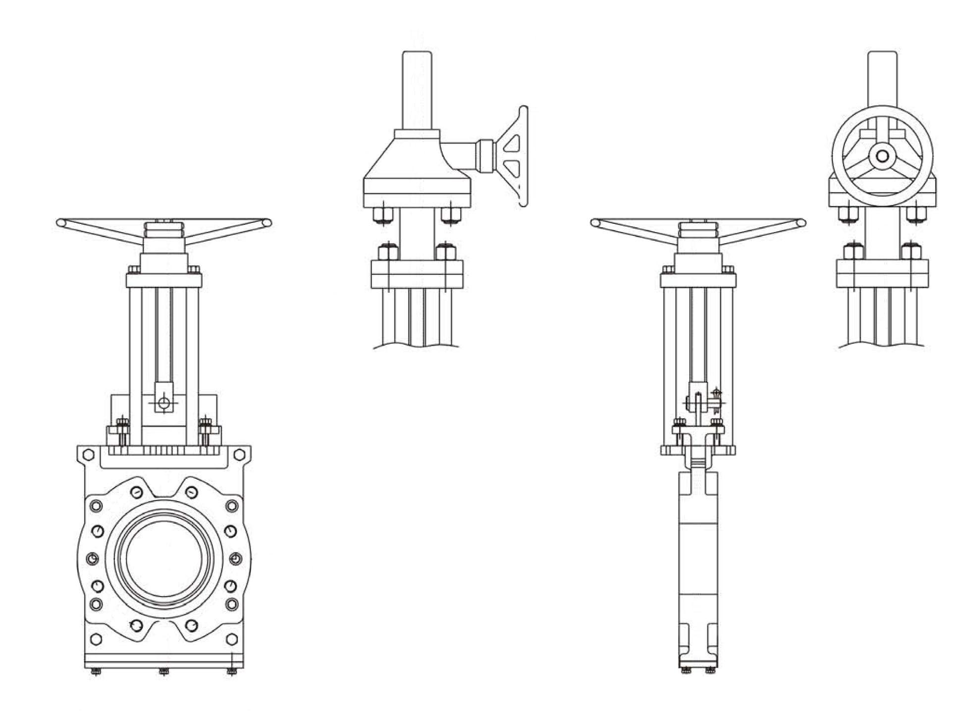
DIMENSIONS WITH BEVEL GEAR
DIMENSIONS WITH PNEUMATIC ACTUATOR (MM)
Application
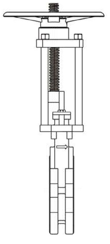
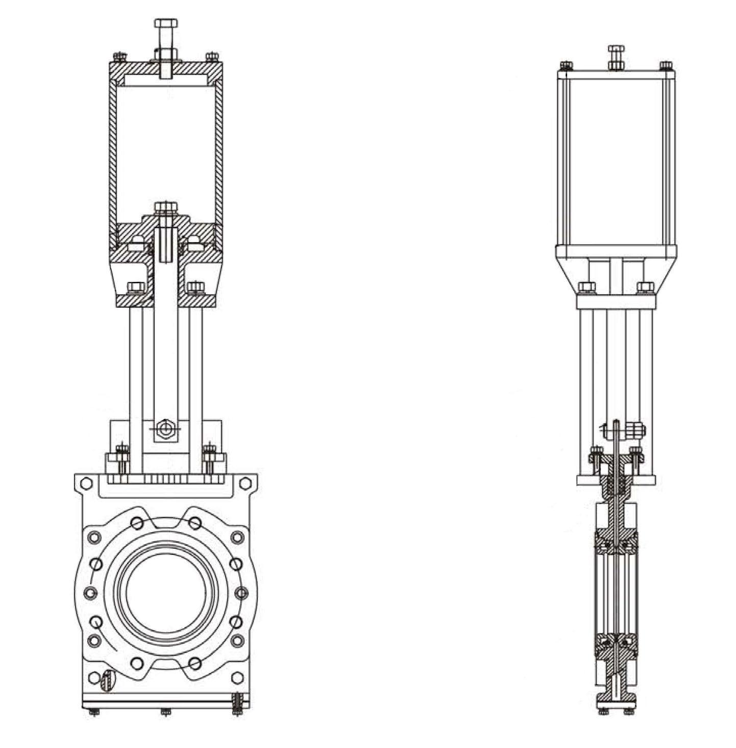
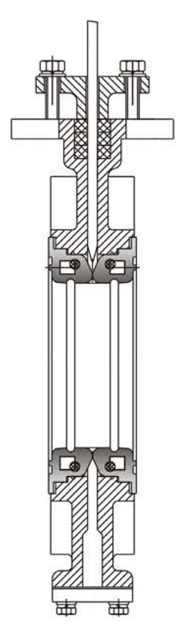
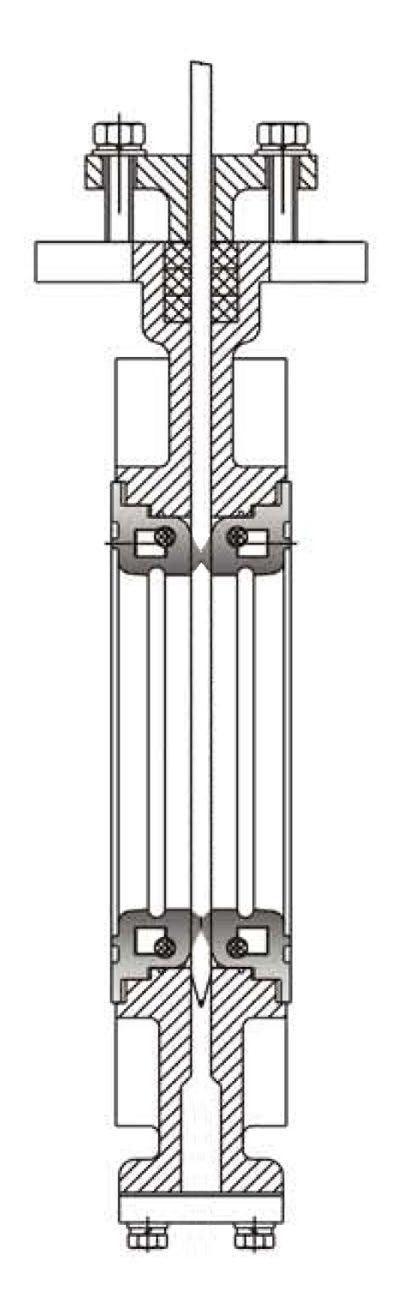
DT/DS series double knife gate valve is typically used for on/off service in pulp making, slurry, residue discharge and sewage treatment.
It is particularly suitable for residue discharge and sewage treatment. It is particularly suitable for residue discharge service on stock cleaners, gravity separators, hydrapulper, etc in the paper making industry.
Features
1. Double gate design shortens the full travel to half that of standard knife gate valves. The operation by twin ‘double acting’ pneumatic cylinders will reduce the opening and closing speed by half.
2. Two-piece body construction with no cavities eliminates product build-up.
3. Tight shutoff, reliable performance.
4. O-ring loaded removable seat is self-compensating with good abrasion resistance and long service life.
5. Available with metal seat, PTFE seat or EPDM seatselection is based on application.
Technical Specification
Nominal diameter DN 100~400
Nominal Pressure 1.0MPa, 1.6MPa, ANSI 150LB
Working Temperature -29~100°C, -29~230°C
Air Pressure 5~7 bar
Connection Type Wafer
MATERIALS LIST
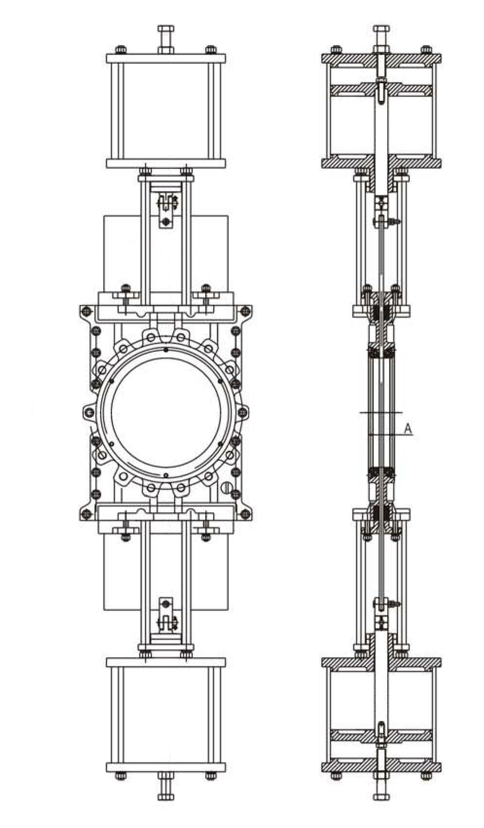
DIMENSIONS WITH PNEUMATIC ACTUATOR (MM)
DIMENSIONS WITH PNEUMATIC ACTUATOR (MM)
S Handwheel G Bevel Gear
Pneumatic Actuator
Hydraulic Actuator
ADC Rising Stem
AQB Rising Stem
AQU Bi-directional
DCAQU Bi-directional
AQM Bi-directional
DCNP Rising Stem
DCA Non-rising stem type
DCB Non-rising gate type
DCF Square knife gate type
DC-SDF Sleeved slurry valve
DT O-port full conduit
DCD Funnel type
DCS Double knife gate valve
DK Lined slurry valve
DC-HSV Bonneted rising stem
60 Series Metal Seat
61 Series Resilient Seat
QSL Series Metal/Resilient Seat
Uni-directional* B Bi-directional Flow Direction 3
* Some models do operate in non preferred direction at lower pressures, refer drawing.
EPDM L SS316L hard Chrome plating* L1 SS316L Stellite surfacing M SS316 hard Chrome plating* M1 SS316 Stellite surfacing
NBR P SS304 hard Chrome plating* P1 SS304 Stellite surfacing
PTFE
VITON
Special
70 Series O-port * Where applicable
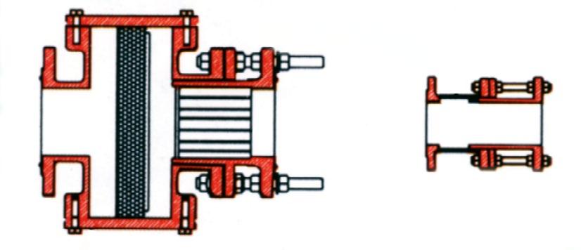
The ‘TF’ Series Pinch Valve is designed specifically to replace Diaphragm Valves and has the same face-to-face dimension. This single anvil valve out performs and outlasts most diaphragm valves.
The 100% Full Port design eliminates any dead spots or crevices and the valve is an extension to the pipe in the fully open position, with no turbulence and no head loss.
The valves are supplied with manual Hand wheel operation or may be fitted with all types of Actuators for both ON / OFF and accurate repeatable linear flow control.
DIMENSIONS
& KG)
(Specify)
The self-cleaning flexing action of the sleeve eliminates inline scaling and blockages. All mechanical parts are completely isolated from the medium. The valve has only five major components, making it easy to use, easy to maintain and it is extremely fitter friendly.
The valve, like all Flowturn Pinch Valves, is bi-directional and offers drop tight shut off across the full pressure range.
The Flowturn Pinch Valve has been designed to solve process problems associated with controlling the flow of abrasive or corrosive fluids. Industries such as mineral processing, pulp and paper, power generation, chemical handling, effluent treatment, water and waste water use the Flowturn Pinch Valve.
The Flowturn Pinch Valve consists of a tough but flexible, full bore cylindrical sleeve which forms part of the pipeline. The valve is closed mechanically via movement of the pinch bars located on opposite sides of the sleeve.
Simple designs are often the best. Most other valve styles use multiple components such as glands, packing, seats, seat retainers, inner linings and outer casing, wear surface, and main control components such as discs, shafts, plugs, gates etc.
Flowturn Pinch Valves utilise a simple sleeve which perform all of the functions listed above.
cover with optional built in lubricator.
Flanged to accommodate ASME/AS/BS/DIN/PN
Sleeve
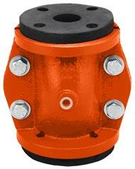
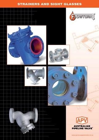
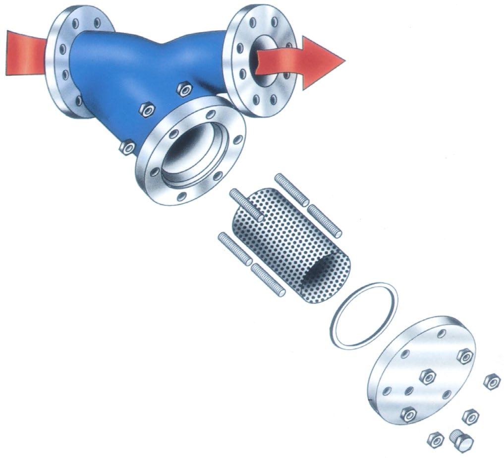
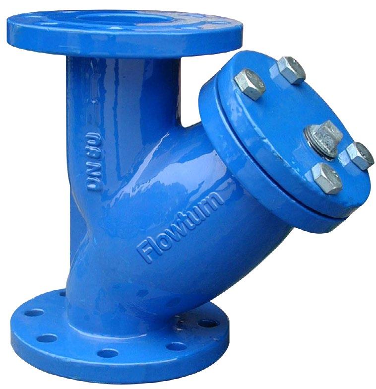
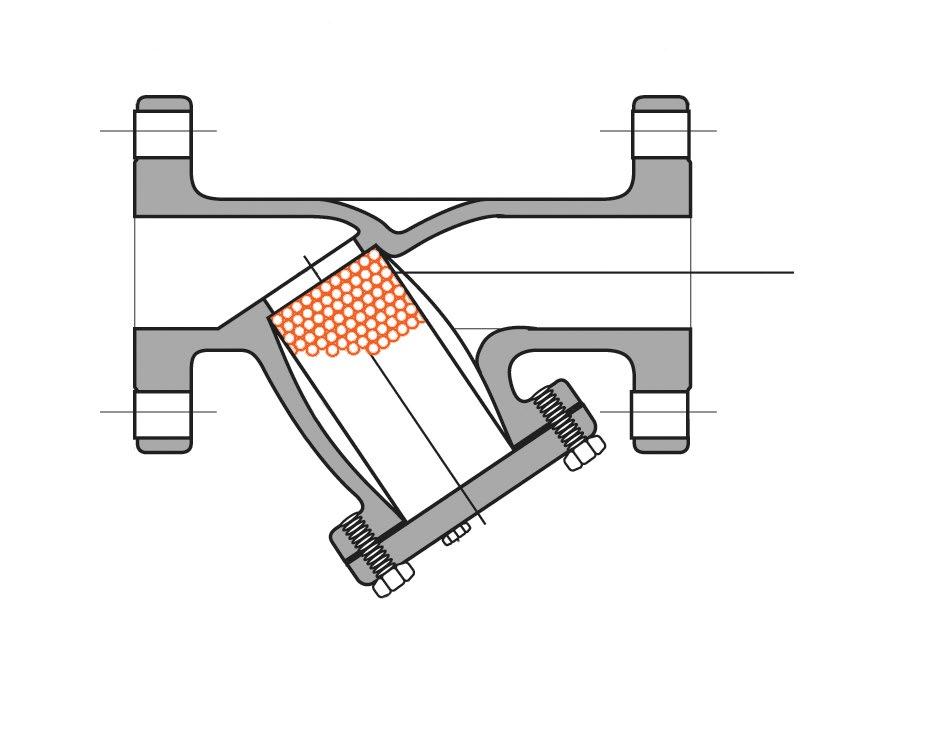
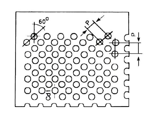
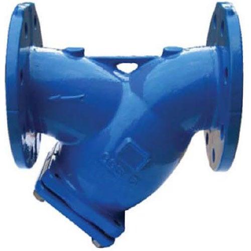
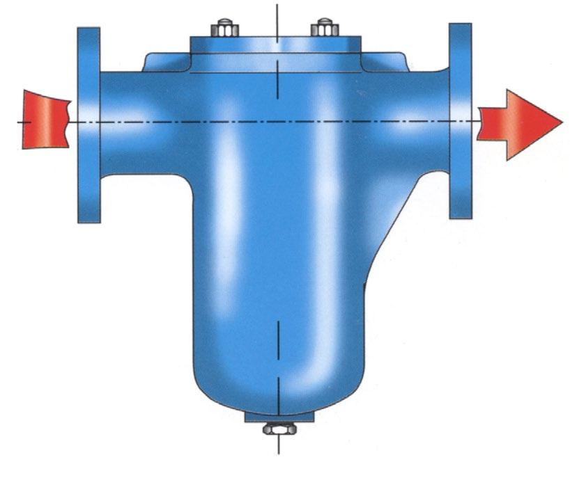
Flanged to Suit 125LB ANSI B16.5, AS 2129 Table D, E / AS 4087 / ISO 7005-1 / AS 4331.1 PN10~21. Y-Type cast iron strainers are manufactured with Heavy Duty Spot welded stainless steel punched screens. Suitable for water, oil & numerous fluid applications. Flowturn strainers average 10 times the open area of the nominal pipe bore. Multiply this by the ‘open area’ of the screen size to calculate total open area. On average, this gives Flowturn strainers 3 to 4 times the pipe bore open area when using standard hole perforation sizes.
Design ASTM F1200-88, BSEN 1074, ANSI B16.1, EN 12266-1. Service Recommendations These strainers are designed for long service. Installation of a strainer before any automatic equipment will ensure trouble free service and avoid the costly repairs or replacements so often caused by the introduction of foreign matter in pipe lines.
Features All sizes feature a bolted cover, as illustrated. Covers normally furnished with blowoff plug.
Screens Heavy gauge perforated stainless steel normally furnished with spot welded seams.
Flanging Available in: ANSI B16.5, AS 2129 Table D/E, AS 4087/AS 4331.1/EN 1092-2/ISO 7005-1 PN10~16 (PN25 and 250LB also available in ductile iron & carbon steel).
Pressure drop in this chart has been calculated using a strainer with 1.6mm hole element on clean water. When the strainer element is partially blocked the pressure drop incurred will be inversely proportional to the area remaining clean
For PN10/14/16/21 and AS Table D, E, F. Refer to drawing.
* Only a guide, will vary all sizes on request.
PRESSURE/TEMPERATURE
As per maximum pressure/temperature ratings indicated in relevant AS/BS/EN/ISO/ASME flange standard. Maximum Temp 220°C (pressure limitations apply at maximum temperature). All strainers are tested to 1.5 times the maximum working pressure. If for high temperature application you must advise so we can use high temperature gasket.
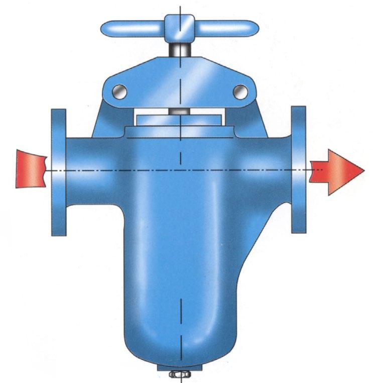
PN25 Flanged and Rated Y-Type cast strainers are manufactured with Heavy Duty spot welded stainless steel punched screens. Suitable for water, oil & numerous fluid applications. Flowturn strainers have 10 times the open area of the nominal pipe bore. Multiply this by the ‘open area’ of the screen size to calculate total open area. On average, this gives Flowturn strainers 3 to 4 times the pipe bore open area when using standard hole perforation sizes.
Service Recommendations These strainers are designed for long service. Installation of a strainer before any automatic equipment will ensure trouble free service and avoid the costly repairs or replacements so often caused by the introduction of foreign matter in pipe lines.
Features All sizes feature a bolted cover, as illustrated. Covers normally furnished with blowoff plug.
Epoxy coated internal & external.
Screens Heavy gauge perforated stainless steel normally furnished with spot welded seams.

AVAILABLE SCREEN TYPES (SS MESH)
Flanging Available in: PN25 - AS 4331.1/EN 1092-2/ISO
7005-1, PN21 - AS 4087, PN35* - AS 4087 (PN25 rated, PN35 drilled), Table F - AS 2129.
*For true PN35 rating, refer 300 class WCB
Flowturn strainer which can be supplied Flanged to suit PN35
Pressure Drop
When the strainer element is partially blocked the pressure drop incurred will be inversely proportional to the area remaining clean.
* Only a guide, will vary all sizes on request.
PN25 rated, maximum cold working pressure 2.5 mPa. Maximum Temp 220°C (pressure limitations apply at maximum temperature). All strainers are tested to 1.5 times the maximum working pressure. If for higher temperature application you must advise so we can use high temperature gasket.
125LB/150 LB/PN10/PN14/PN21
Flanging To Suit ANSI 125, 150 AS 2129 Table D, E, F AS 4087 PN14, PN21 AS 4331.1/EN 1092-1/EN 1092-2/ ISO 7005-1 PN10~25 Integral Cast
STANDARD PRODUCT MATERIAL COMBINATION ANSI CLASS 125/PN10/PN14 Body, Cover, Plug ASTM A126 Class B Iron Screens SS304 Gasket CNAF/PTFE/EPDM/NBR
STANDARD PRODUCT MATERIAL COMBINATION ANSI CLASS 150/PN21
Body, Cover, Plug ASTM B62 - Bronze/A216 WCB Screens SS316 Gasket CNAF/PTFE/NBR/EPDM
Body, Cover, Plug ASTM A216 Grade WCB Screens SS304
Gasket Non-asbestos (CNAF)
Body, Cover, Plug ASTM A351 Gr. CF8M Screens SS316 Gasket Non-asbestos (CNAF)
Class 300 model DKSL01 also available *
* Optional quick release lid (Bridge type shown)
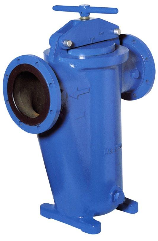
SIZE 50NB to 500NB (2”-20”)
IRON/BRONZE/STEEL 125LB/150 LB/PN10/PN14/PN21
CLASS 150 PRESSURE & TEMPERATURE
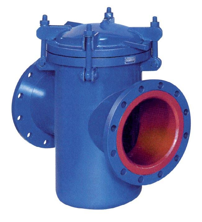
Simplex Strainers 25~300NB (1” to 12”)
Pressure drop strainers with 3/32” or 1/8” perforated baskets
Maximum “dirty” differential must not exceed 70 kPaD
SCREEN
DIMENSIONS
MATERIALS
Australian Pipeline Valve don’t consider in our design the following factors of risk:
1. APV-Flowturn ‘Standard’ Iron valves can be used in a temperature range between -10 to +100°C up to 200°C depending on seals. (Note, pressure limitations apply above 38°C refer to Pressure/Temperature charts.)
Australian Pipeline Valve-Flowturn ‘Standard’ iron valves are not suitable for low temperature service below -10°C.
2. The onus is on the customer to specify all materials of construction and service conditions. Australian Pipeline Valve shall assume standard materials and conditions if not otherwise specified.
3. Australian Pipeline Valve ‘Standard’ valves are not equipped with devices suitable to avoid internal over-pressures caused by incorrect operations of process or by-fluids & liquids subjected to an increase of volume and/or pressure (Back-seating is not provided unless specifically stated).
4. Australian Pipeline Valve ‘Standard’ valves are not designed with special devices to withstand a sudden thermal jump (thermal shock).
5. In general Australian Pipeline Valve ‘Standard’ valves are not mechanically designed to bear overloads due to exceptional atmospheric or natural phenomenon’s (such as earthquakes).
6. In general Australian Pipeline Valve ‘Standard’ valves are not designed to bear loads on flanges, on pipe connections or pipe-line.
7. In general Australian Pipeline Valve ‘Standard’ valves can’t withstand ice inside their bodies (in this case the user has to consider the optional stem extension for insulating, avoiding the presence of residual product inside the valve).
8. The compatibility between the valves construction materials and medium is selected by the user. The user is ultimately responsible for verifying the compatibility between medium and materials.
9. Abrasive or dirty service applications need to be considered and stated at time of order.
10. APV-Flowturn valves are suitable for liquid working pressures specified (cold working pressure ‘cwp’ j) on drawing and only when used in hydraulic installations in which shock is absent or negligible. The sudden closure of a valve in a hydraulic system causes the body of liquid, which may be moving at a rate generally in excess of one foot per second, to stop instantaneously. As liquids are relatively incompressible, the sudden cessation of flow effects a rise in pressure considerably greater than the static working pressure. This pressure increase is termed “SHOCK” and may, in some cases, be sufficient to cause valves or piping to fail.
Pressure increase due to shock is not dependent upon the working pressure in the system but upon the velocity at which the liquid is flowing. This pressure surge, or shock, severely limits design velocities...a fact readily understandable if it is remembered that pressure rise resulting from arrest of flow may be as high as 414 kPa (60 psi) for each foot per second initial velocity. For example, installations of 689 kPa (100 psi) and 6895 kPa (1000 psi) working pressures, with the same initial velocity of 305 cm (10 feet) per second, will be subject to the same increase in pressure, approximately 4137 kPa (600 psi) due to instantaneous closure of a valve.
Shock generally prevails in lines equipped with check or quick-closing valves, or in lines supplied by reciprocating pumps. It may also be produced, to a lesser degree, by rapid closure of gate and globe valves. Therefore, care should be exercised when closing valves installed in liquid lines.
Where shock is likely to occur, the maximum shock pressure should be added to the working pressure (‘cwp’ j) of the line to determine working pressure of products in the line...also, hydraulic installations should be equipped with air chambers or other types of shock absorbers to eliminate, as much as possible, increase in pressure due to shock.
j Cold Working Pressure ‘cwp’ : where ‘Cold Working Pressure’ is the maximum rated pressure of the valve at a temperature up to 65°C (150°F). Pressure rating shown on drawing, labels and certificate is always cold working pressure non-shock.
VALVE START-UP
Before installing the valve onto the pipe-line it is mandatory, for the user, to verify the compatibility of the valve with service conditions (medium, temperature and pressure). With reference to standard valves held in stock, the reseller and end user will have to assure themselves of the compatibility between the valve and the conditions required by the customer. Australian Pipeline Valve gate valves must be only used for on-off (fully open/fully closed) service.
Before using the valve in a potential explosive atmosphere it’s necessary for the customer to: -
• To verify the correct type of valve and operator is specified.
• To verify the compatibility between the valve and the zone in which the valve should be installed
• To foresee the pipe-line ground condition on which the valve should be installed
• To check that the temperature if the valve surface is not higher than the flammable point of the atmosphere
in which the valve is installed (in this case specify an insulating cover device for the valve & an extension for the operator)
• To avoid mechanical knocks during the installation that may cause sparks.
Australian Pipeline Valve cannot be held responsible for damage caused by use of the product for any reason, especially if it is improper use or modified.
“Australian Pipeline Valve produces isolation, control and flow reversal protection products for severe and critical service media in utility, steam, pipelines, oil & gas and process industries. APV valves and pipeline products form the most competitive portfolio in the market.”