


Quality is Our First Priority.
Consistent product quality and a proven track record makes Australian Pipeline Valve a dependable choice where total reliability is the number one concern.
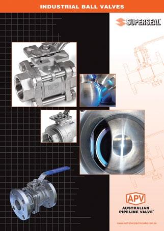
Since its founding, APV’s philosophy has been focused on quality. Our valves are manufactured in full compliance to worldwide standards (such as ASME/ANSI, API, EN, ISO, BS, AS).
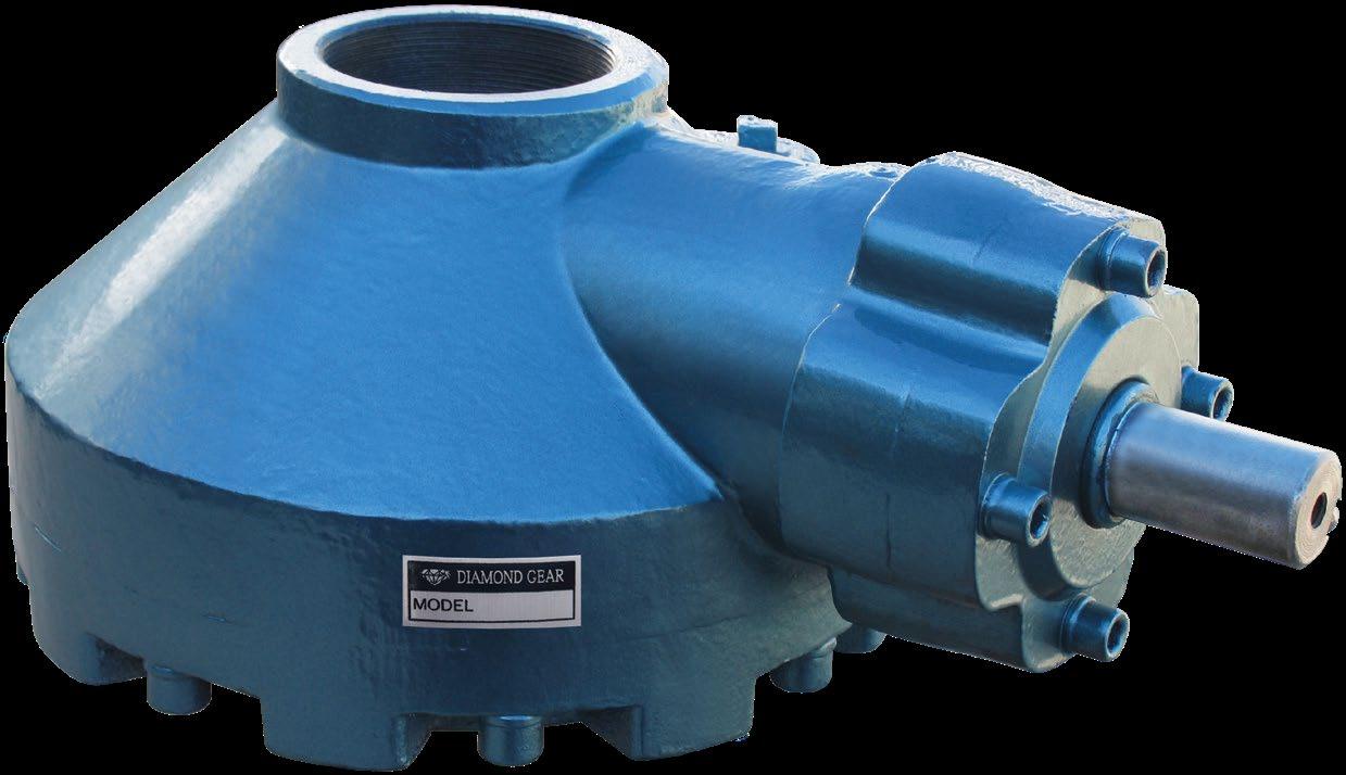

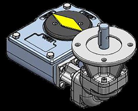
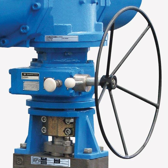
O-ring sealed and permanently lubricated. Fully weather resistant for outdoor service.
High strength cast steel enclosure.
Accepts stem protector in NPT or metric threads.
Comprehensive product line for torque capability.

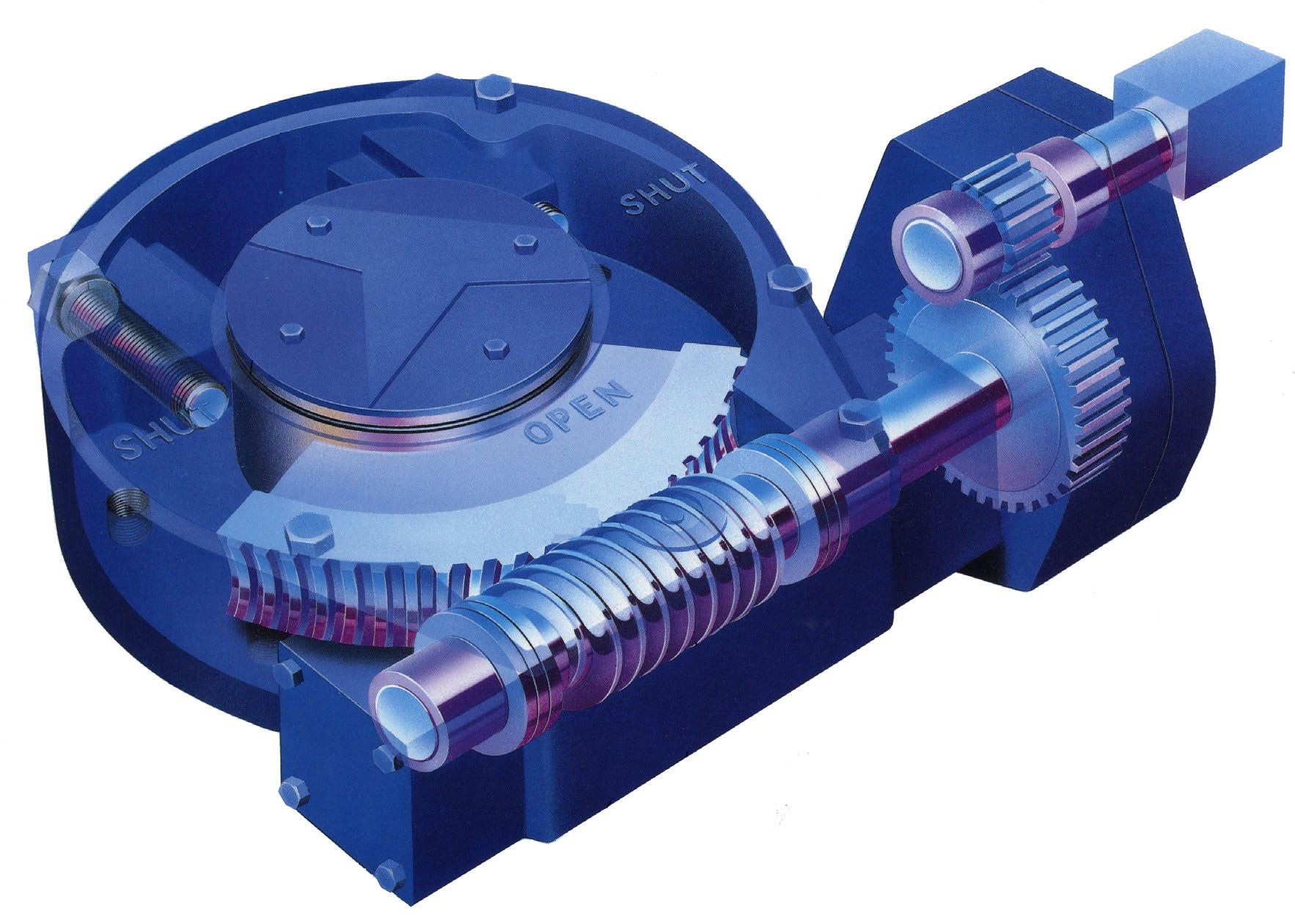
Bevel pinion and bevel gear supported by anti-friction bearings.
nut (splined) can be removed & machined to match valve, 42mm includes thread depth.
No couplings or brackets are supplied. The splined stem nut insert (13) in gearbox can be removed and ACME threaded to match valve stem. Alternatively the stem nut from your existing valve can be utilised, a simple coupler then needs to be made to match gear box.
No couplings or brackets are supplied. The splined stem nut insert (13) in gearbox can be removed and ACME threaded to match valve stem. Alternatively the stem nut from your existing valve can be utilised, a simple coupler then needs to be made to match gear box.
No couplings or brackets are supplied. The splined stem nut insert (13) in gearbox can be removed and ACME threaded to match valve stem. Alternatively the stem nut from your existing valve can be utilised, a simple coupler then needs to be made to match gear box.
No couplings or brackets are supplied. The splined stem nut insert (13) in gearbox can be removed and ACME threaded to match valve stem. Alternatively the stem nut from your existing valve can be utilised, a simple coupler then needs to be made to match gear box.
No couplings or brackets are supplied. The splined stem nut insert (13) in gearbox can be removed and ACME threaded to match valve stem. Alternatively the stem nut from your existing valve can be utilised, a simple coupler then needs to be made to match gear box.
ROUGH REFERENCE SIZING CHART FOR BEVEL GEAR BOXES BA SERIES ON ‘TYPICAL’ GATE/GLOBE VALVES BBOSY, API 600/BS 1873/API 623
3”
8”
10”
28”
30” BA3
This is only a rough ready reckoner, sizing should be correctly calculated by client.
This assumes maximum ‘delta p’ (maximum cold working pressure) and has been calculated using the highest torque & largest stem size and torques of the 3 major manufacturers evaluated and includes a further 20% safety factor. However it is the purchase’s sole responsibility to correctly choose the right gearbox.
Gearbox sizing is based on bolted bonnet valves with graphite stem packing. PTFE stem packing will be significantly lower torque. 100nb to 250nb 150 & 300 class API 603 gate valves are usually lower torque than API 600. Gearbox sizing will vary depending on actual valve torque as well as bonnet type, packing, hand wheel size, mounting, stem size, design standard, trim, wedge/disc type, service media & temperature, packing type, etc.
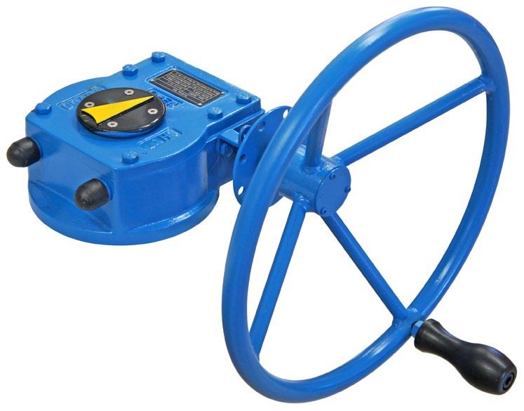
Optional open/close indicators
External mechanical stops allow +/-50 travel.
Fully weather resistant for outdoor service.
O-ring sealed and permanently lubricated along with gears and bearings.
High strength cast iron enclosure.
Industry inter-changeable pre-drilled mounting pattern per MSS SP 101.
Custom gear mounting pattern, boring and keyway patterns.
Worm gear dual position mounting capability for easy reversal of rotation direction.
Comprehensive product line for torque capability.
Machine generated self-lock gearing assures minimum backlash and smooth operation.
Optional square operating nut allows for removal of handwheel and operation by a reach rod.
*Easily converted for motorized applications.
Thrust bearings provide reliable smooth operation
*Heavy duty components must be specified for motor operation
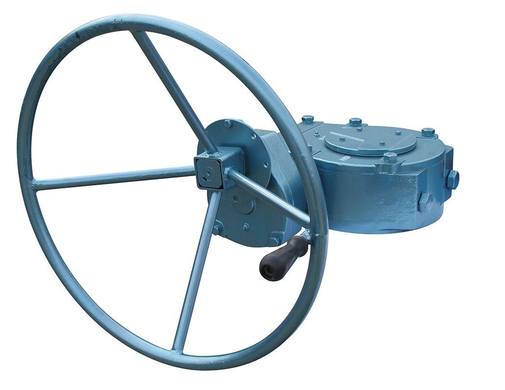
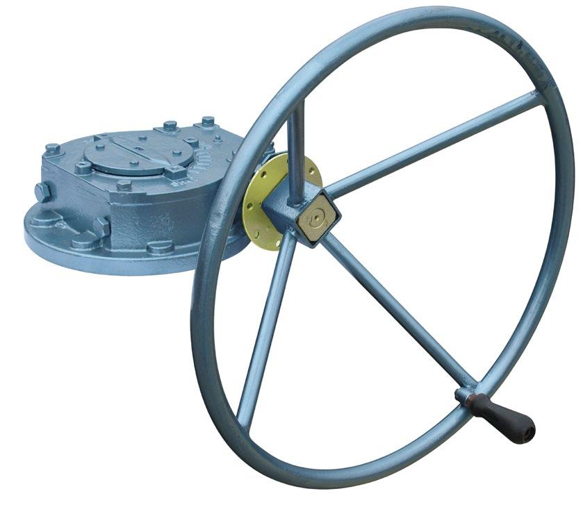
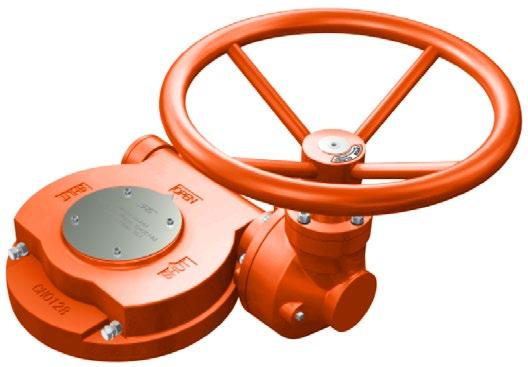
Rugged, dependable, precision performance for valves requiring 90° rotation.
• Reliable rugged worm gear boxes with position indicators & adjustable Travel/stop screws for 1/4 turn ball valves, plug valves etc.
• Weatherproof housing, manufactured from high strength ductile iron, seals at bottom of worm gear hub to protect & isolate internal operating parts from dirt and water.
• Carbon steel one-piece input shaft and worm gear are supported by ball or tapered roller bearings for increased efficiency. No sleeve bearings are used in any model.
• Durable ductile iron worm segments are standard.
• Adjusting screws allow a + or - 5° range at end of travel.
• Permanently lubricated with generous amounts of high quality grease. Grease fittings are standard on all models.
QUICK REFERENCE
* Other drillings on request
DIMENSIONS
Rugged, dependable, precision performance for valves requiring 90° rotation.
• Reliable rugged worm gear boxes with position indicators and adjustable Travel/stop screws for 1/4 turn ball valves, plug valves etc.
• Weatherproof housing, manufactured from high strength ductile iron, seals at bottom of worm gear hub to protect and isolate internal operating parts from dirt and water.
• Carbon steel one-piece input shaft and worm gear are supported by ball or tapered roller bearings for increased efficiency. No sleeve bearings are used in any model.
• Durable ductile iron worm segments are standard.
• Adjusting screws allow a + or - 5° range at end of travel.
• Permanently lubricated with generous amounts of high quality grease. Grease fittings are standard on all models.
DIMENSIONS
Rugged, dependable, precision performance for valves requiring 90° rotation.
• Reliable rugged worm gear boxes with position indicators and adjustable Travel/stop screws for 1/4 turn ball valves, plug valves etc.
• Weatherproof housing, manufactured from high strength ductile iron, seals at bottom of worm gear hub to protect and isolate internal operating parts from dirt and water.
• Carbon steel one-piece input shaft and worm gear are supported by ball or tapered roller bearings for increased efficiency. No sleeve bearings are used.
• Durable ductile iron worm segments are standard.
• Adjusting screws allow a + or - 5° range at end of travel.
• Permanently lubricated with generous amounts of high quality grease. Grease fittings are standard on all models.
* Other drillings on request
Rugged, dependable, precision performance for valves requiring 90° rotation.
• Reliable rugged worm gear boxes with position indicators and adjustable Travel/stop screws for 1/4 turn ball valves, plug valves etc.
• Weatherproof housing, manufactured from high strength ductile iron, seals at bottom of worm gear hub to protect and isolate internal operating parts from dirt and water.
• Carbon steel one-piece input shaft and worm gear are supported by ball or tapered roller bearings for increased efficiency. No sleeve bearings are used.
• Durable ductile iron worm segments are standard.
• Adjusting screws allow a + or - 5° range at end of travel.
• Permanently lubricated with generous amounts of high quality grease. Grease fittings are standard on all models.
Also available in subsea (IP67) and low temperature configurations up to 320,000NM
* Other drillings on request
DIMENSIONS
Rugged, dependable, precision performance for valves requiring 90° rotation.
• Reliable rugged worm gear boxes with position indicators and adjustable Travel/stop screws for 1/4 turn ball valves, plug valves etc.
• Weatherproof housing, manufactured from high strength ductile iron, seals at bottom of worm gear hub to protect and isolate internal operating parts from dirt and water.
• Carbon steel one-piece input shaft and worm gear are supported by ball or tapered roller bearings for increased efficiency. No sleeve bearings are used.
• Durable ductile iron worm segments are standard.
• Adjusting screws allow a + or - 5° range at end of travel.
• Permanently lubricated with generous amounts of high quality grease. Grease fittings are standard on all models.
Also available in subsea (IP67) and low temperature configurations up to 320,000NM
* Other drillings on request
Rugged, dependable, precision performance for valves requiring 90° rotation.
• Reliable rugged worm gear boxes with position indicators and adjustable Travel/stop screws for 1/4 turn ball valves, plug valves etc.
• Weatherproof housing, manufactured from high strength ductile iron, seals at bottom of worm gear hub to protect and isolate internal operating parts from dirt and water.
• Carbon steel one-piece input shaft and worm gear are supported by ball or tapered roller bearings for increased efficiency. No sleeve bearings are used.
• Durable ductile iron worm segments are standard.
• Adjusting screws allow a + or - 5° range at end of travel.
• Permanently lubricated with generous amounts of high quality grease. Grease fittings are standard on all models.
(IP67) and
QUICK REFERENCE
* Other drillings on request
DIMENSIONS
Rugged, dependable, precision performance for valves requiring 90° rotation.
• Reliable rugged worm gear boxes with position indicators and adjustable Travel/stop screws for 1/4 turn ball valves, plug valves etc.
• Weatherproof housing, manufactured from high strength ductile iron, seals at bottom of worm gear hub to protect and isolate internal operating parts from dirt and water.
• Carbon steel one-piece input shaft and worm gear are supported by ball or tapered roller bearings for increased efficiency. No sleeve bearings are used.
• Durable ductile iron worm segments are standard.
• Adjusting screws allow a + or - 5° range at end of travel.
• Permanently lubricated with generous amounts of high quality grease. Grease fittings are standard on all models.
Also available in subsea (IP67) and low temperature configurations up to 320,000NM
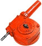
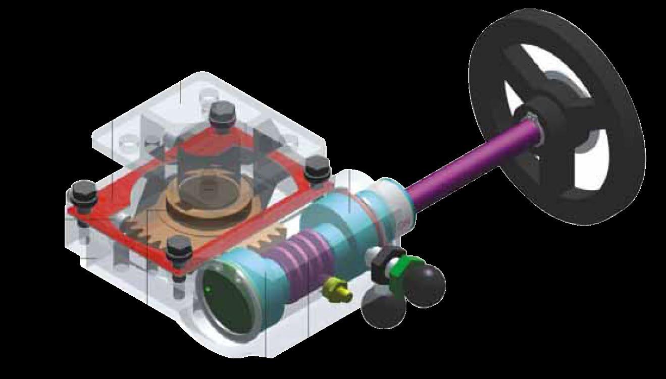
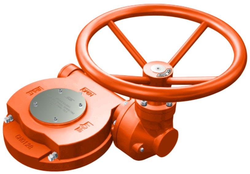
FEATURES
• Compact and light weight
• There are two keyway 90° apart to allow mounting east-west or north-south.
• Pull out the positioning pin & rotate the off-centre device 180° to engage the gearbox, disengage the opposite way.
• The gear operator is filled with a special lubricant. The gearbox waterproof and made to IP65.
• The bottom of gear operator should be connected to the valve (bracket mounting), the top is connected to the actuator with the valve stem going through the inner hole inserts
• The unit can be switched between manual gear & automatic actuator operation but does not allow engagement of both devices at the same time. The cylinder of the gear operator engages to the valve stem & disengages the actuator in one position, then in the other position this is reversed.
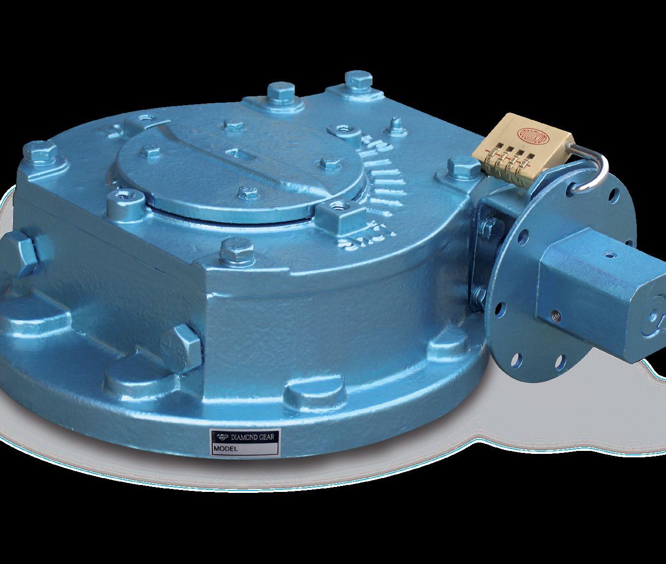
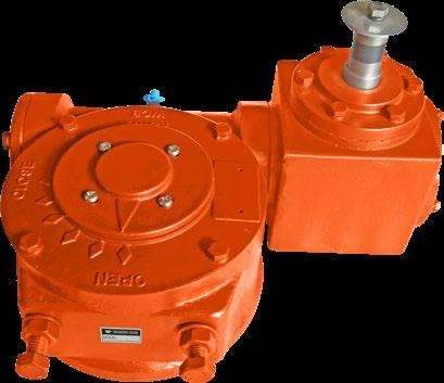
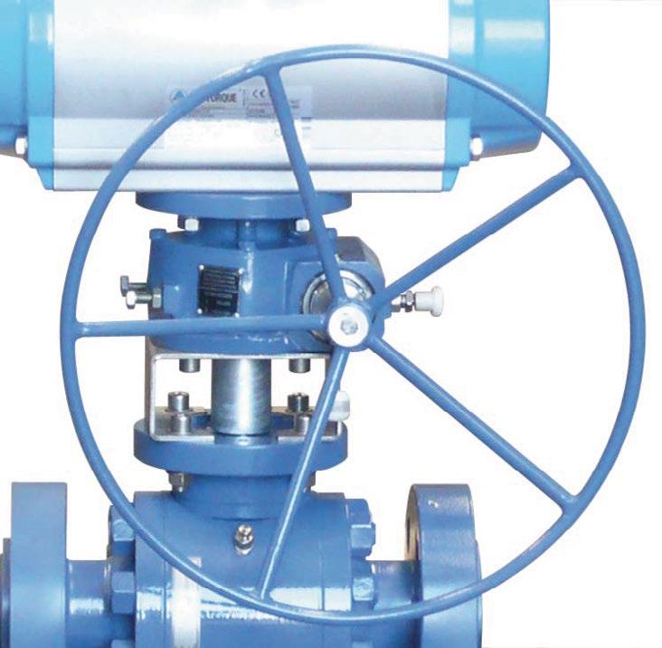
MO Series manual override is an emergency device for the opening and closing of a valve in case of a pneumatic actuator failure. It’s self-locking worm gear design provides safe & easy operation for transferring between control & manual operation.
The MO Series declutchable gear operators provide an easy and reliable method of direct manual operation that can be utilised to over-ride the actuator as emergency control on air failure, or as a local control in the event of controller malfunction. When the hand wheel is clutched in, the valve is then under local manual control and the remote control is ‘locked out’.

Model MOS-1 / MOS-2 / MOS-3 / MOS-4 / MOS-5 / MOS-7 / MOS-8
Torque Range 100 to 9800 Nm
Temperature -20°C to +80°C
Stroke Adjustment ±10 Movement 0° to 90°
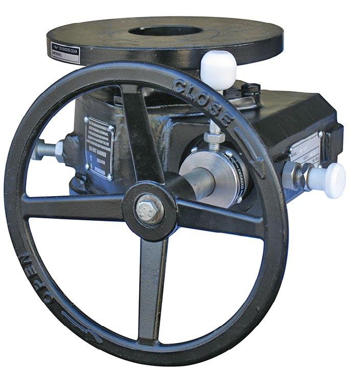
MOS declutchable gear box provides reliable manual positioning of valves, allowing existing pneumatic or hydraulic rotary actuators to be over ridden. All Diamond Gear MOS gearboxes are suitable for outdoor use. The self-locking rugged design allows easy & safe operation, positive manual positioning & long life.
For manual operation, pull out the spring clutch lever and then rotate the clutch lever clockwise until fully engaged. Anticlockwise lever movement will disengage manual operation and the valve is recoupled direct to the automatic actuator. When under manual control, the valve remains locked in the last set position.
The MOS gearbox is supplied with two stroke adjusting bolts. These bolts must be set for valve positioning and to avoid damage during manual operation. The limit stops on actuators are overridden when fitted with MO - Gearboxes. For stroke angle less than 80°, consult us.
ASSEMBLY CODES
S - Standard
R - Reversed operation: handwheel on the other side (factory option).
SPECIFICATIONS
Body Heavy Cast Aluminium or Ductile Iron.
Gear Quadrant Aluminium bronze or SGI 600/3.
Worm shaft Hard anodized, high grade aluminium or ENB. Temperature -20°C to +85°C. (Specials on request).
Stroke Adjustment +5° and -5° at each end.
Movement 0° - 90°.
Coating Polyurethane coating.
Fasteners Stainless steel.
IN CASE OF USING SPRING RETURN PNEUMATIC ACTUATOR ADD THE ACTUATOR TORQUE SPRING TO THE TORQUE OF VALVE TO CALCULATE TORQUE OF MANUAL OVER-RIDE.
MOS-05SGS to MOS08SGS see page 32
NOTES:-
A. Stem bore and stem entry length is to be considered by customer. While calculating total stem entry deduct entry of adaptor / coupling length in length ‘L’ of worm wheel.
B. Raised face (Spigot) as per std IS 521 can also be provided on Request.
BILL
*For MOS 05SGS to MOS 08SGS see page 32
NOTES:-
A. Thrust spacers (6) have been provided for MOS-01 to MOS-05 models, instead of ball thrust bearing.
*B. MOS-01 to MOS-04 do not have retainer plate (7). The cams are retained by circlips.
C. Bushes (16) as per requirement only, depending on models.
**D. MOS-01 to MOS-03 will have collar ring (17) assembly.
DIMENSIONS - MOS 05SGS ~ MOS 08SGS
“Australian Pipeline Valve produces isolation, control and flow reversal protection products for severe and critical service media in utility, steam, pipelines, oil & gas and process industries. APV valves and pipeline products form the most competitive portfolio in the market.”