

Quality is Our First Priority. Consistent product quality and a proven track record makes Australian Pipeline Valve a dependable choice where total reliability is the number one concern. Since its founding, APV’s philosophy has been focused on quality. Our valves are manufactured in full compliance to worldwide standards (such as ASME/ANSI, API, EN, ISO, BS, AS).


Australian Pipeline Valve valves are designed, manufactured and tested in accordance with API, ANSI, ASME, and BS requirements. The following list contains the most important applicable standards for ball valves. Australian Pipeline Valve valves may be produced in accordance with other international standards on request.
API - American Petroleum Institute
• API 6D Specification for Pipeline Valves (Gate, Plug, Ball and Check Valves)
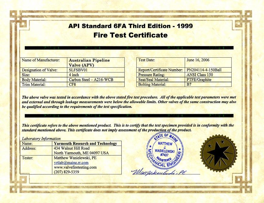
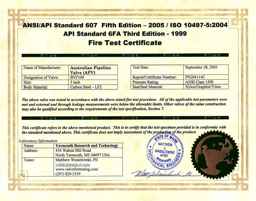
• API 6FA Specification for Fire Test For Valves
• API 598 Valve Inspection and Testing
• API 607 Fire Test for Soft-Seated Quarter-turn Valves
• API Q1 Specification for Quality Programs for the Petroleum and Natural Gas Industry
ANSI - American National Standard Institute
• B16.5 Steel Pipe Flanges and Flange Fittings
• B16.10 Face to Face and End to End Dimensions of Valves
• B16.25 Butt-Welding Ends
• B16.34 Valves, Flanged, Threaded, and Welding End
British Standard
• BS 5351 Steel Ball Valves for the Petroleum, Petrochemical and Allied Industries
• BS 6755 Testing of Valves
• BS 5146 Inspection and Test of Valves
• BS 1503 Steels for Fired and Unfired Pressure Vessels
• BS 5160 Steel Pipe Flanges and Flanged Fittings for the Petroleum Industry
• BS 2080 Face-to-Face, Center to Face, End to End, and Centre to End Dimensions of Flanged and Butt-Welding End Steel Valves for the Petroleum, Petrochemical and Allied Industries
• BS 4504 Flanges and Bolting for Pipes, Valves and Fittings
ISO - International Organisation for Standardisation
• ISO 9001 Quality Systems - Model for Quality Assurance in Design, Development, Production, Installation and Servicing
• ISO 5211 Valve Actuator Attachment
MSS - Manufacturers Standardisation Society
• SP6 Standard Finishes for Contact Faces of Pipe Flanges and Connecting-End Flanges of Valves and Fittings
• SP25 Standard Marking System for Valves, Fittings, Flanges and Unions
• SP72 Ball Valves with Flanged or Butt-Welding Ends for General Service
NACE - National Association of Corrosion Engineers
• MR0175 Sulfide Stress Cracking Resistant Metallic Materials for Oil Field Equipment
ASTM Casting Specification Common Designation Service Applications
ASTM A216 Grade WCB Carbon Steel Non-corrosive applications including water, oil and gases at temperatures between -20°F (-30°C) and +800°F (+425°C)
ASTM A352 Grade LCB
Temp Carbon Steel
temperature applications to -50°F (-46°C). Not for use above +650°F (+340°C).
ASTM A352 Grade LCB Low Temp Carbon Steel Low temperature applications to -50°F (-46°C). Not for use above +650°F (+340°C).
ASTM A352 Grade LC1 Low Temp Carbon Steel Low temperature applications to -75°F (-59°C). Not for use above +650°F (+340°C).
ASTM A352 Grade LC2 Low Temp Carbon Steel Low temperature applications to -100°F (-73°C). Not for use above +650°F (+340°C).
ASTM A352 Grade LC3 3 1/2% Nickel Steel Low temperature applications to -150°F (-101°C). Not for use above +650°F (+340°C)
ASTM A217 Grade WC6 1 1/4% Chrome 1/2% Moly Steel Non-corrosive applications including water, oil and gases at temperatures between -20°F (-30°C) and +1100°F (+593°C).
ASTM A217 Grade C9 2 1/4% Chrome Non-corrosive applications including water, oil and gases at temperatures between -20°F (-30°C) and +1100°F (+593°C).
ASTM A217 Grade C5 5% Chrome 1/2% Moly Mild corrosive or erosive applications as well as non-corrosive applications at temperatures between -20°F (-30°C) and +1200°F (+649°C).
ASTM A217 Grade C12 9% Chrome 1% Moly Mild corrosive or erosive applications as well as non-corrosive applications at temperatures between -20°F (-30°C) and +1200°F (+649°C).
ASTM A487 Grade CA6NM 12% Chrome Steel Corrosive application at temperatures between -20°F (-30°C) and +900°F (+482°C).
ASTM A217 Grade CA15 12% Chrome Corrosive application at temperatures up to +1300°F (+704°C)
ASTM A351 Grade CF8M 316 SS Corrosive or either extremely low or high temperature non-corrosive services between -450°F (-268°C) and +1200°F (+649°C). Above +800°F (+425°C) specify carbon content of 0.04% or greater.
ASTM 351 Grade CF8C 347 SS Primarily for high temperature, corrosive applications between -450°F (-268°C) and +1200°F (+649°C). Above +1000°F (+540°C) specify carbon content of 0.04% or greater.
ASTM A351 Grade CF8
ASTM A351
Grade CF3
304 SS Corrosive or extremely high temperatures non-corrosive services between -450°F (-268°C) and +1200°F (+649°C). Above +800°F (+425°C) specify carbon content of 0.04% or greater.
304L SS Corrosive or non-corrosive services to +800°F (+425°C).
ASTM A351 Grade CF3M 316L SS Corrosive or non-corrosive services to +800°F (+425°C).
ASTM A351 Grade CN7M Alloy 20 Good resistance to hot sulfuric acid to +800°F (+425°C).
ASTM 743 Grade M3-35-1 Monel Weldable grade. Good resistance to corrosion by all common organic acids and salt water. Also highly resistant to most alkaline solutions to +750°F (+400°C).
ASTM A743 Grade N-12M Hastelloy B Is well suited for handling hydrofluoric acid at all concentrations and temperatures. Good resistance to sulphuric and phosphoric acids to +1200°F (+649°C).
ASTM A743 Grade CW-12M Hastelloy C Good resistance to strong oxidation conditions. Good properties at high temperatures. Good resistance to sulphuric and phosphoric acids to +1200°F (+649°C).
ASTM A743 Grade CY-40 Inconel Very good for high temperature service. Good resistance to strongly corrosive media and atmosphere to +800°F (+425°C).
ASTM B62 Bronze Water, oil or gas: up to 400°F (205°C). Excellent for brine and seawater service.
STANDARD FORGED VALVE MATERIALS
ASTM Designation Description Common Service Recommendations Body/Bonnet Material Casting Comparison
A105(1) Carbon Steel
A350-LF2 Low Temperature Carbon Steel
A182-F11(2) 1-1/4% Cr, 1/2% Mo Alloy Steel
A182-F22(3) 2-1/4% Cr, 1% Mo Alloy Steel
A182-F6 5% Cr, 1/2% Mo Alloy Steel
A182-F9 9% Cr, 1% Mo Alloy Steel
A182-F304 18% Cr, 8% Ni Stainless Steel
General service such as oil, oil vapor, gas, steam and water at temperatures -20° to 1000°F (-28°C to 537°C) A216-WCB
Suitable for temperatures -50°F and not above 650°F (-45°C and not above 343°C) A352-LCB
For high temperatures from -20° to 1100°F to minimise graphitisation (-28°C to 593°C) A217-WC6
For services requiring greater strength than F11 at temperatures from -20° to 1100°F (-28°C to 593°C)
For corrosive/erosive refinery use requiring resistance at temperatures from -20° to 1100°F (-28°C to 593°C)
A217-WC9
A217-C5
For services involving media with higher sulphur content to combat oxidation to 1100°F (593°C) A217-C12
For corrosive services and atmospheres from -20° to 1000°F (-28°C to 537°C)
A182-F316 18% Cr, 8% Ni, 2% Mo Stainless Steel For superior resistance to corrosion to 1000°F (537°C)
(1) Permissible but nor recommended for prolonged use above 800ºF (425ºC)
(2) Consideration should be given to the possibility of excessive oxidation (scaling) when used above 1050ºF (563ºC)
Material Description
HASTELLOY Nickel Alloy
INCONEL INCOLOY Nickel Alloy
MONEL Nickel-Copper Alloy
TITANIUM Metal
ASTM A182 F51 Ferritic-Austenitic ‘Duplex’ Stainless Steel
ASTM A182 F55
A351-CF8
A351-CF8M
Service Recommendations
Good high temperature properties. Excellent corrosion resistance in hydrochloric acid.
For high temperature service. Used for nuclear applications.
For corrosive service up to 842°F (450°C). Resistant to sea water, acids, alkalies.
Good resistance to corrosion together with low specific weight
Very high strength, resistance to corrosion, pitting and stress corrosion in chloride media.
Ferritic-Austenitic ‘Super Duplex’ Stainless Steel Higher strength, resistance to corrosion, pitting and stress corrosion in chloride media.
ASTM A182 F44 Austenitic Stainless Steel Very high strength, high resistance to corrosion
Trim Description Application
Electroless Nickel Plated For oil & gas and general services requiring long service life and superior hardness and good corrosion resistance.
13% Cr, Type 410 Stainless Steel For oil & gas and general services requiring long service life with superior hardness and good corrosion resistance. Also superior strength for high pressure balls and stems.
Type 316 Stainless For liquids and gases corrosive to 410 Stainless Steel up to 850°F (455°C)
Type F51/S31803 Duplex Stainless For liquids and gases corrosive to 410 Stainless Steel up to 850°F (455°C) requiring longer service with superior hardness and good corrosion resistance. Also superior strength for high pressure balls and stems.
Monel For corrosive service to 842°F (450°C) such as acids, alkalies, salt solutions, etc.
NACE Specially treated specific hardness trim combined optionally with B7M Bolts and 2HM nuts to meet NACE MR-01-75 requirements
Note: This chart is for general reference only. Australian Pipeline Valve recommends that customers’ engineers analyse service requirements and specify the materials they consider optimum for their service conditions.
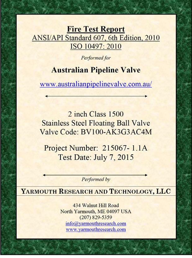
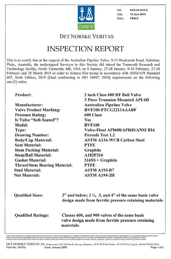
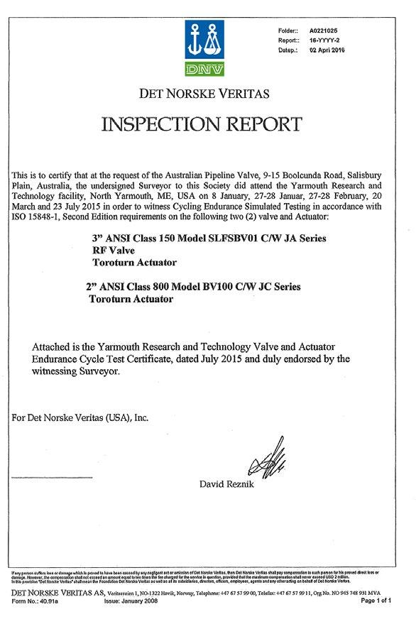
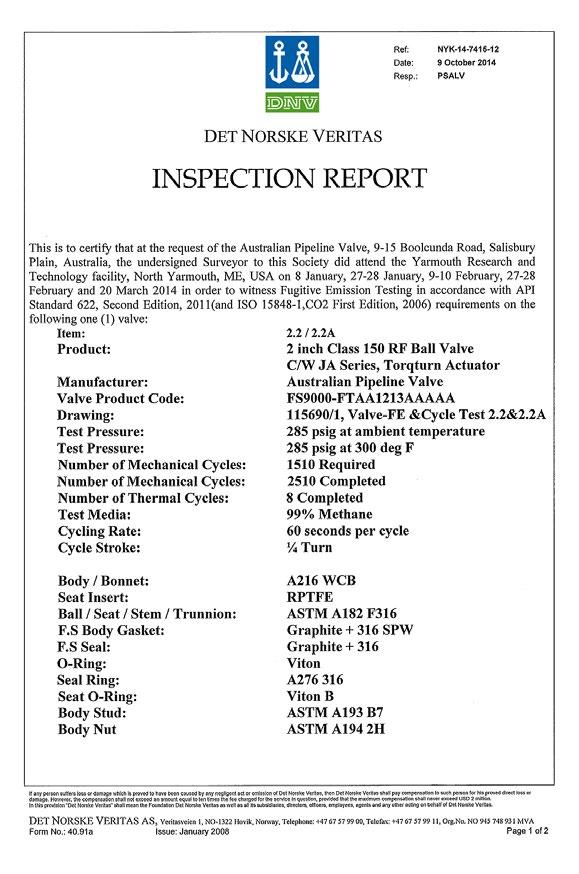
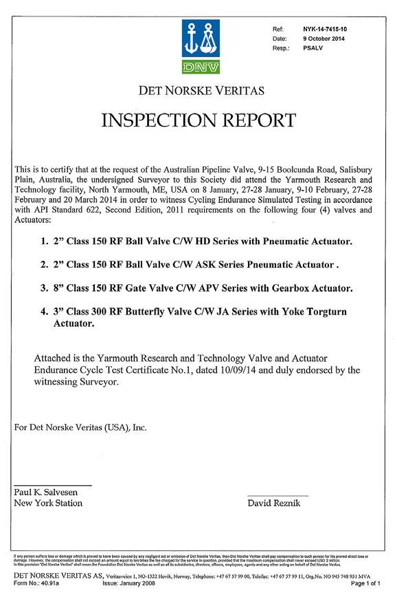
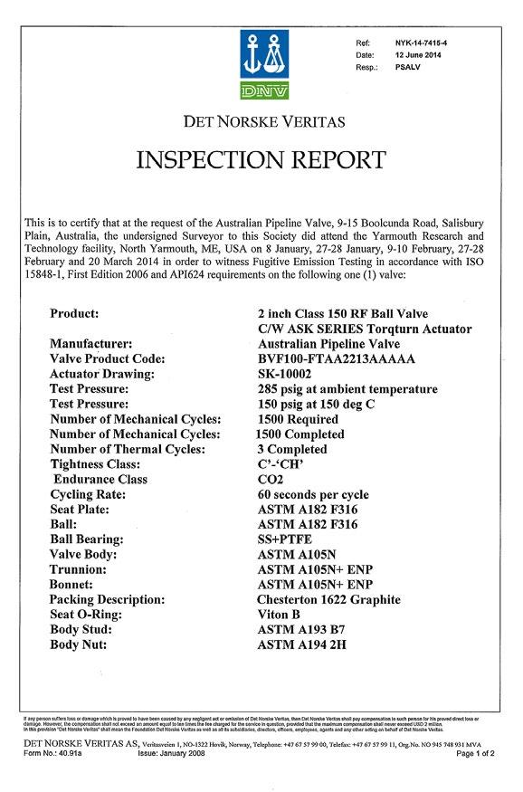
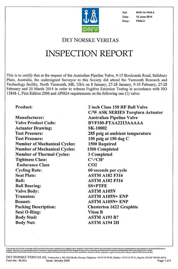
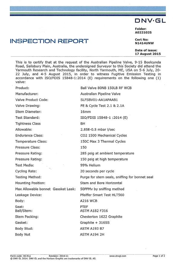
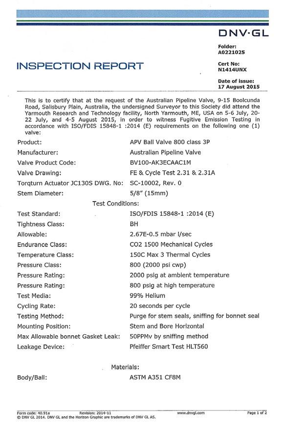
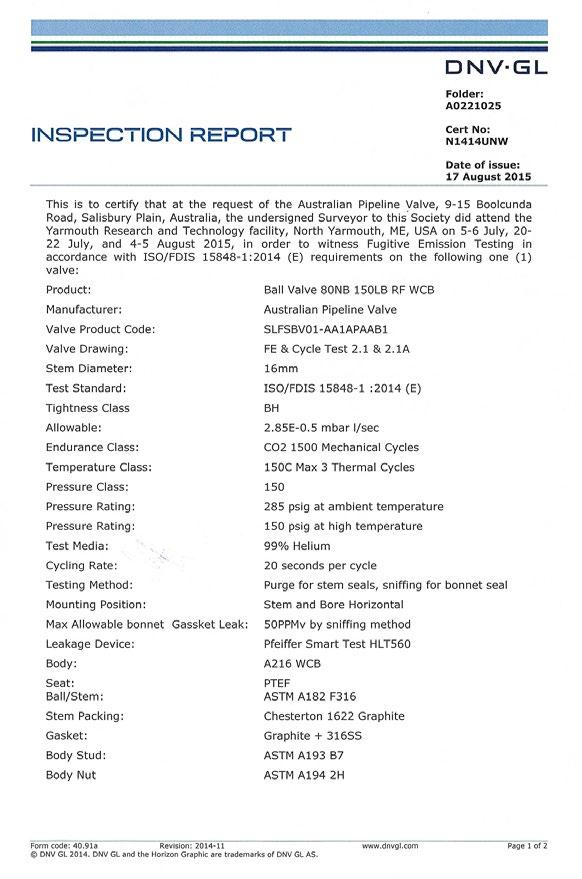
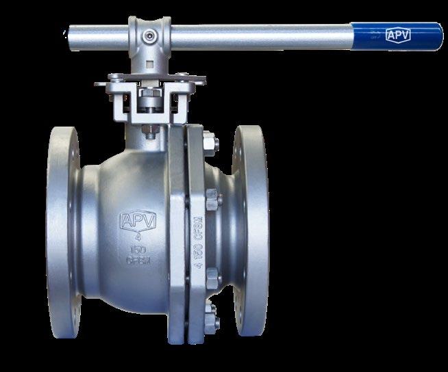
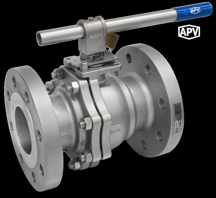
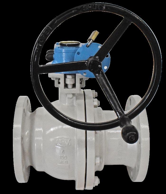
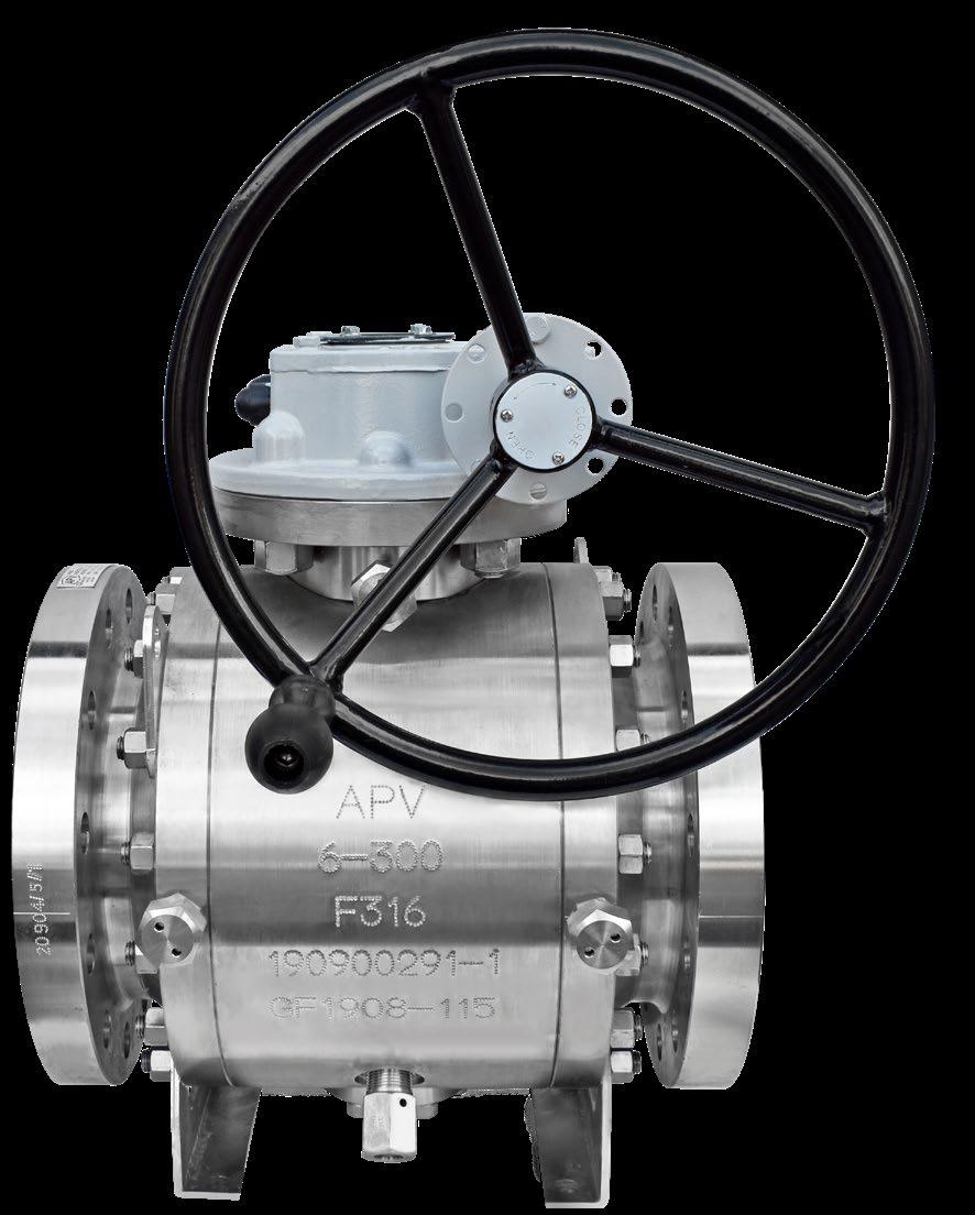
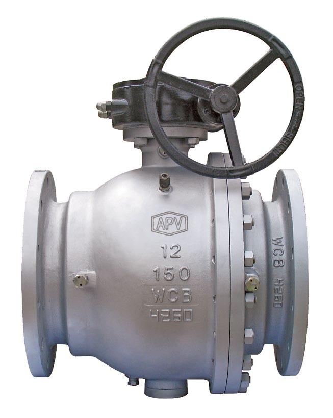
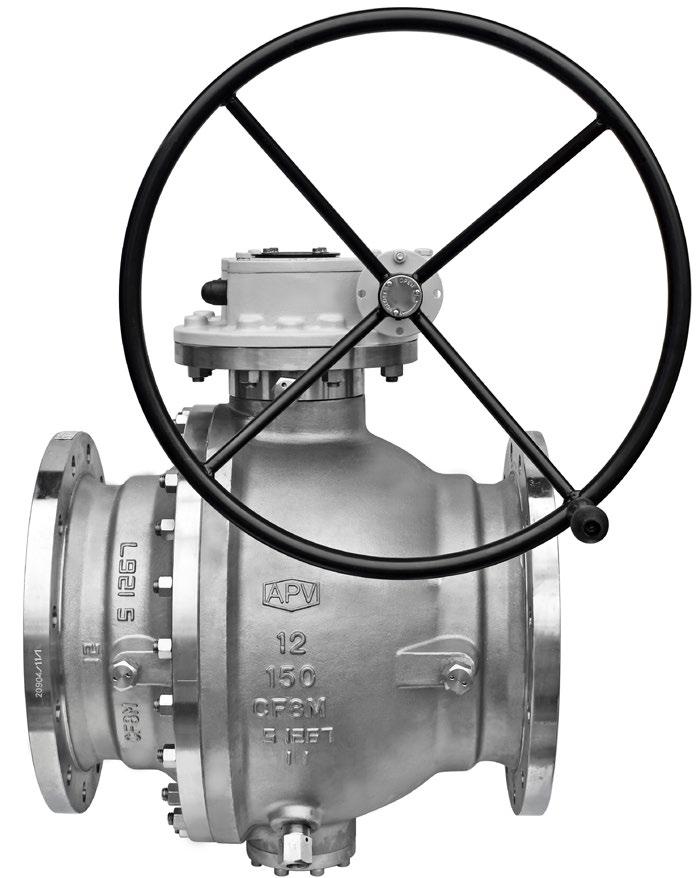
Australian Pipeline Valve is one of the few companies in the world to hold firesafe certification to the latest 6th edition of API 607 and ISO 10497. In addition, APV ball valves are fugitive emission certified to ISO 15848.


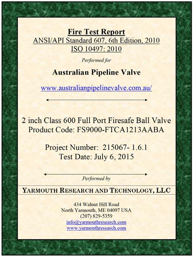

ASTM A351 - CF8M & CF8 AND ASTM A216 - WCB
NACE MR0175 (CLASS III BOLTING) FOR SOUR SERVICE
ISO 5211 TOP flange for Actuation
• API 6D & API 608
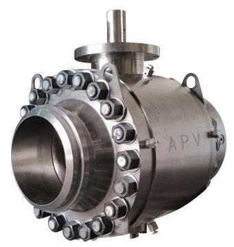
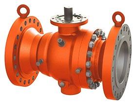
• 250NB (10”) & over trunnion mounted *
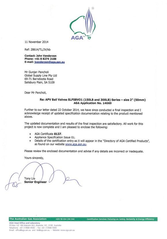
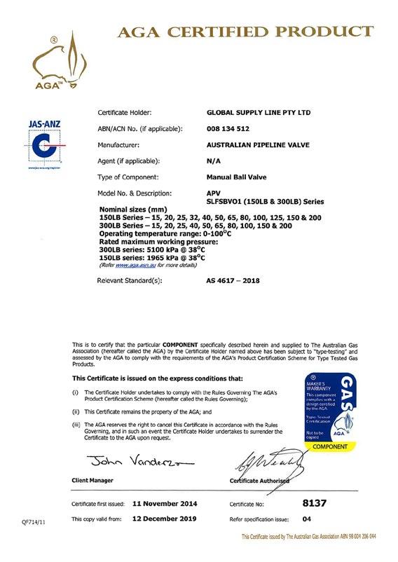
• Aga Approved
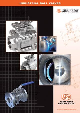
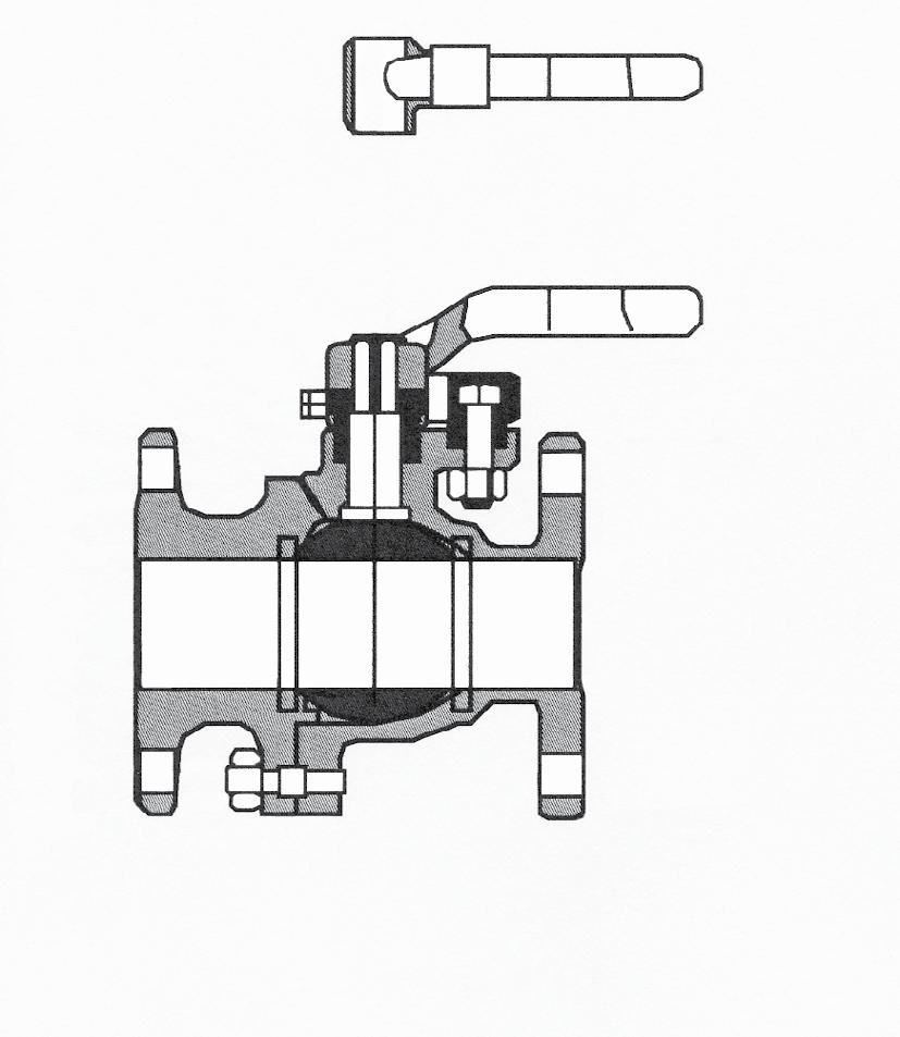
• Full bore solid ball
• Investment Cast or Forged
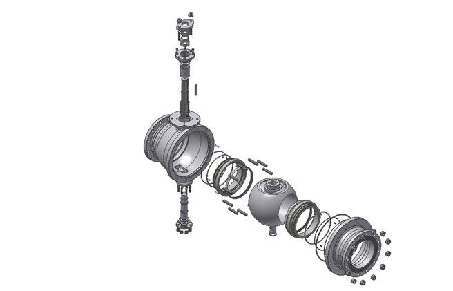
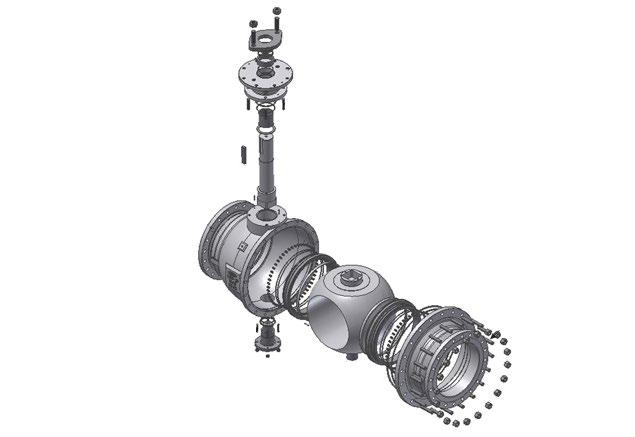
• Split Body 2 piece design
• Anti Blow-Out Stem
• Anti-Static Device
• Firesafe Design to API 607 and API 6FA
• Temperature Range -25°C to 230°C
• Also available in metal seats and PEEK seats
• Also available in Monel, Duplex, Alloy 20 etc.
* 250NB (10”) & 300NB (12”)150LB avaliable in floating and trunnion
23
24
25
26


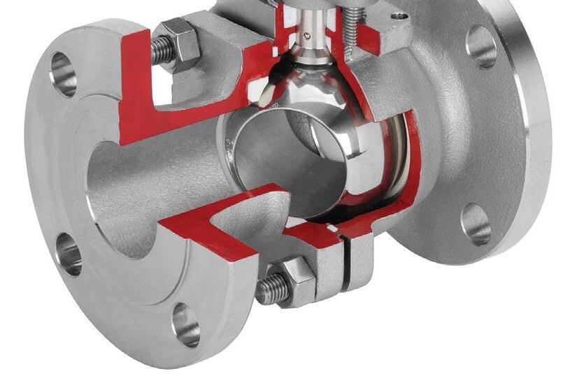
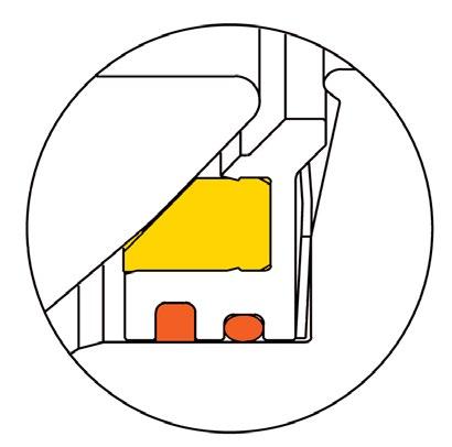
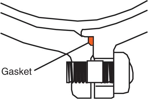
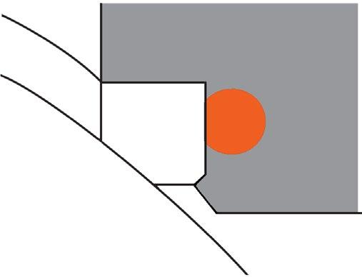
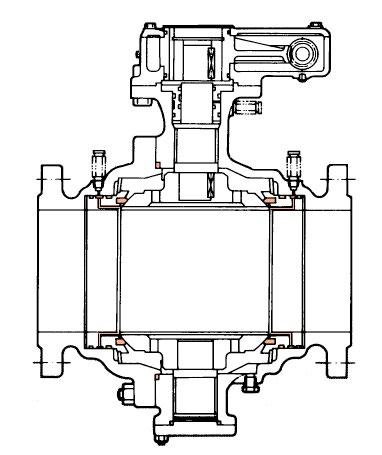
BODY GASKET
Gasket is designed so that the outer circumference of the gasket is in metal to metal contact with the valve body flange.
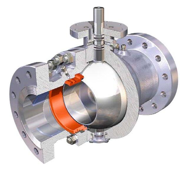
BODY SEAT
The seat is carefully designed for perfect sealing at low and high pressure ranges, as well as for minimised operating torque. If the seat ring is burnt, the ball is pressed against the metal body by fluid pressure, effecting a seal.
DIMENSIONS ANSI-150LB
DIMENSIONS ANSI-150LB
*Trunnion support ball, see FS9000.
DIMENSIONS ANSI-300LB
*Trunnion support ball, see FS9000. Torque is maximum breakaway at maximum differential (running torque is approx 1/3 of breakaway). A 25% factor is included, but torques assume clean wet fluids like water/oil. Torques shown are for RPTFE for PTFE seats torques are 30% lower. TFM1600 energised low torque seats also available.
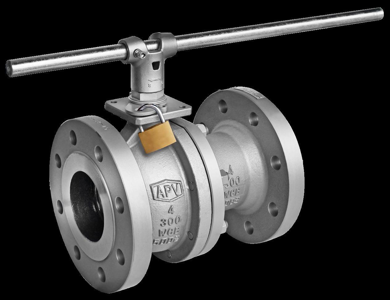
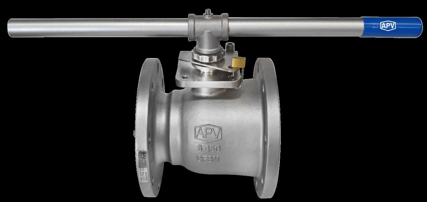
Optional direct mount pad adjustable packing gland which is accessable for tightening without API 608 compliant.
(Encapsulated)


High tensile High Strength Stem
Adapts readily to our wide range of pneumatic and electric actuators. Blow-out proof design.
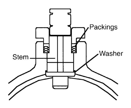
Packing
Multi-ring adjustable packing offers secure, dynamic sealing with low torque.
Elastomer free design option.
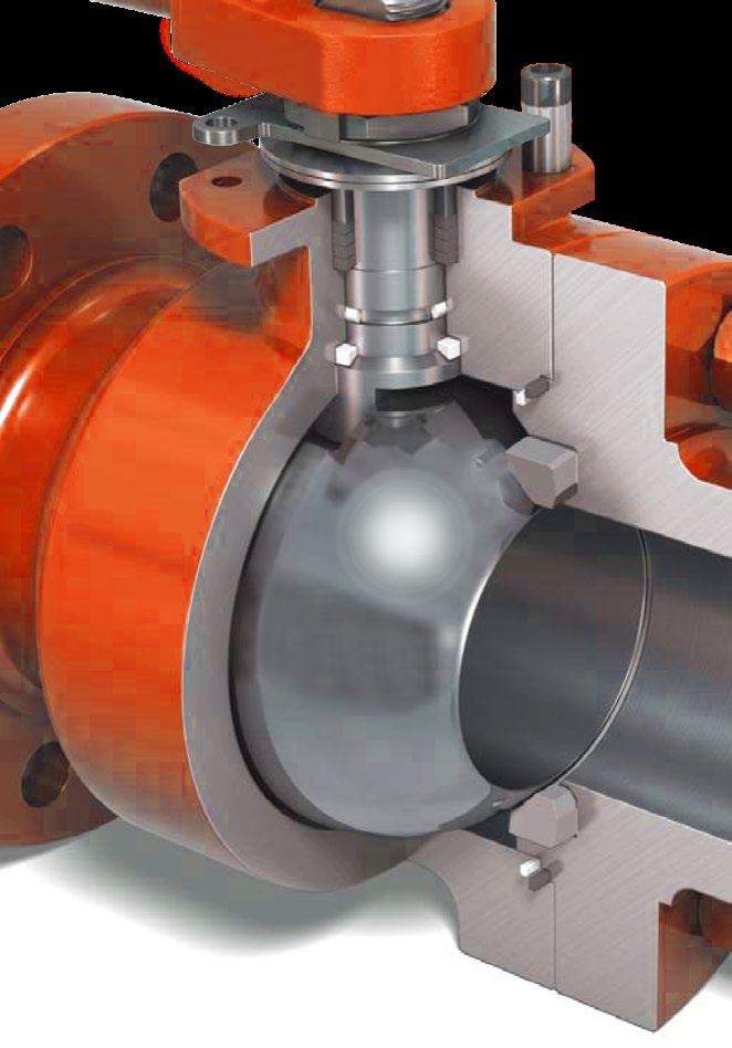
Encapsulated Body Seal
With secondary metal to metal body sealing.
Live loaded seats
Flexible cavity relief capable seats.
High Flow Capacity
Full bore opening offers higher Cv values and ensures lower pressure drops.
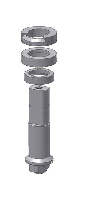
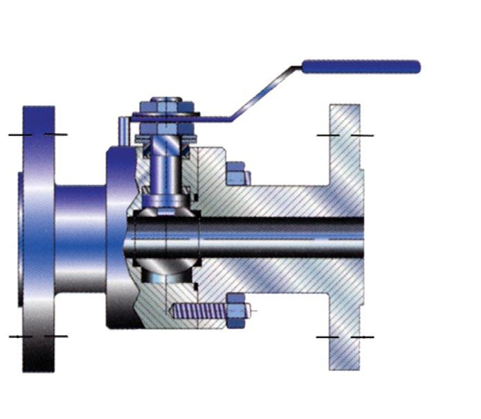
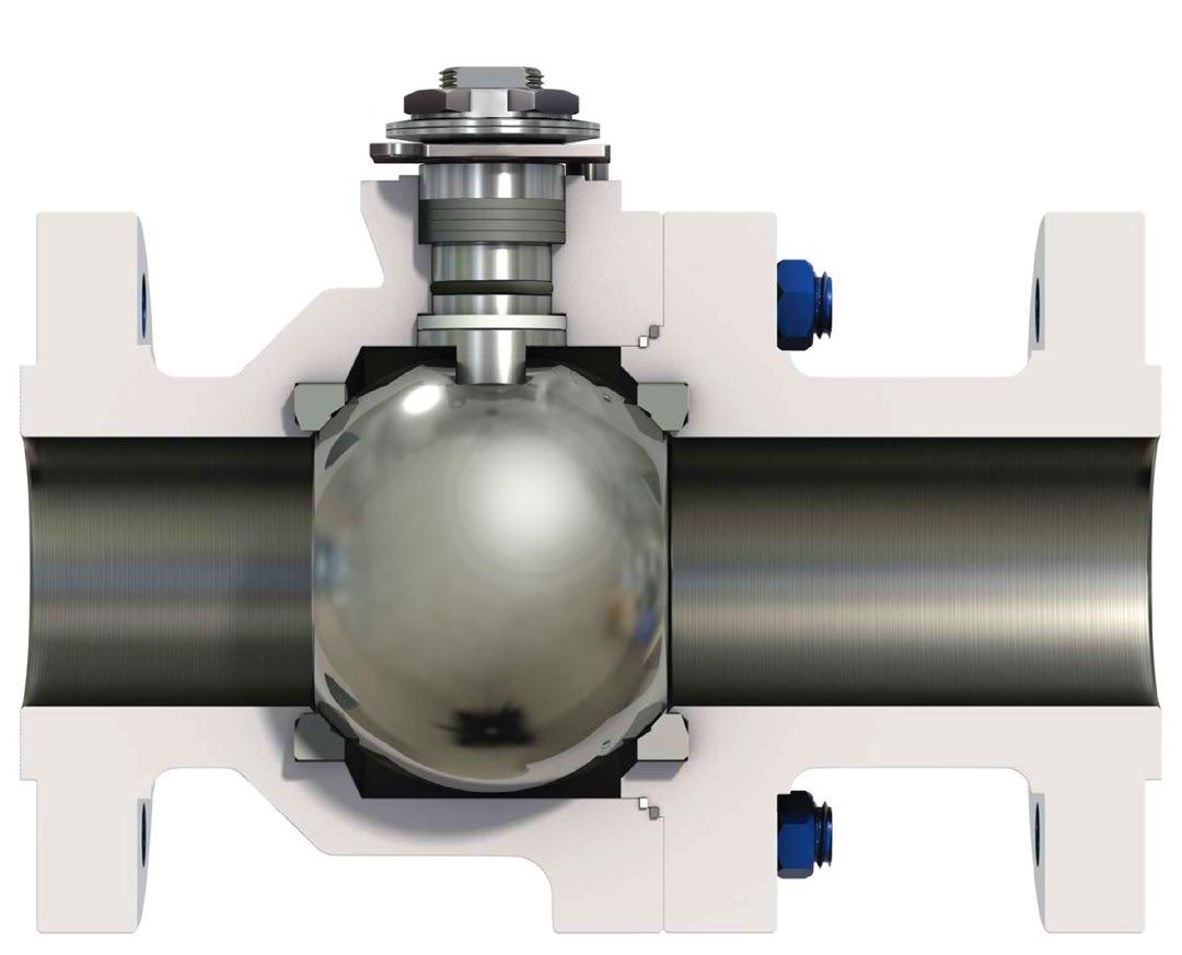
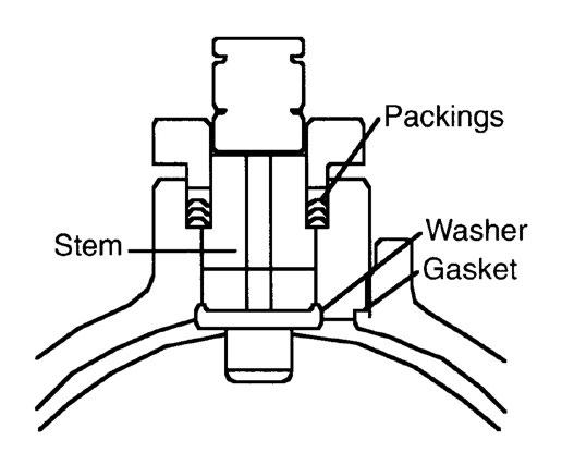
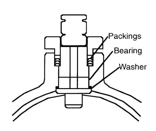
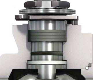
Stem assembly
The stem rotates in a reinforced PTFE bearing which eliminates excessive load on the packing and helps to reduce torques. Design varies according to size/class. (Direct mount pad version, refer to drawing.)
Packing
Gland Bearing Stem Thrust Bearing/Washer
Anti-static device
Protects against potentially dangerous electrostatic discharges.
Anti-Static device
Ensures electrical conductivity
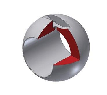
Vent Hole
Pressure balanced hole in ball
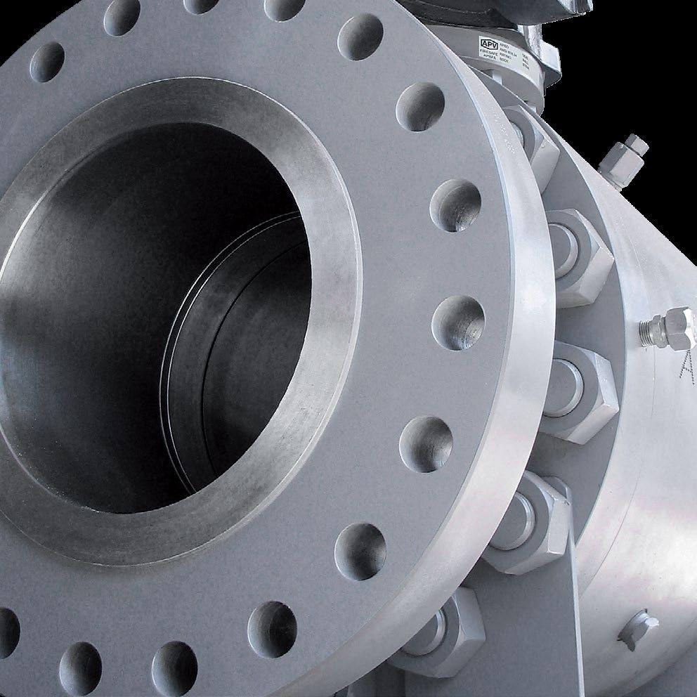
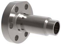
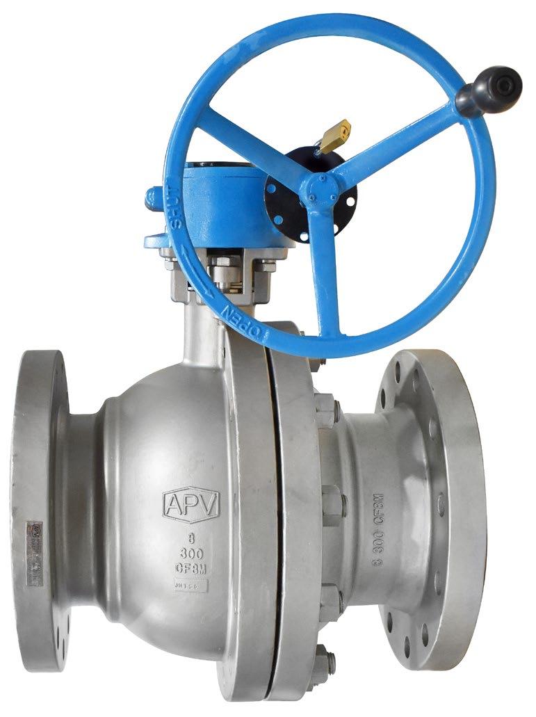
Flanges
ASME (ANSI) CI. 150/300/600 flanges are standard. Other end connections are also available.
Rugged heavy-Duty Body
We offer a lifetime guarantee on our casting if the valves are used within our design parameters. Heavy wall to ANSI B16 dual conforming API 608.
Safety (Vent) Hole
Pressure balanced design. Relieves the pressure differential between the body cavity and the ball port to prevent buildup of trapped pressure and to prolong the life of the stem packing/seals. (80NB & above)
Seat design.
Low and high pressure zero leakage capability.
Large contact face.
Flexible design and radial grooves on sides of seats ensure upstream pressure balances cavity pressure.
DIMENSIONS ANSI-600LB
For 600LB to 200NB (8”) Floating see BVF100-F26 (Ball Special) *150 x 111mm standard bore also available. Refer to drawing.
DIMENSIONS ANSI-900/1500LB
Designed to outlast other valves in a wider range of service conditions.
A. Valve size 15A (1/2”) to 25A (1”)
B. Valve size 40A (1-1/2”) to 65A (2-1/2”)
C. Valve size 80A (3”) to 100A (4”)
D. Valve size 125A (5”) to 250A (10”) Carbon PTFE & PEEK will do higher temperatures
Our valve design can be specified with inert elastomer free seals, providing a wider service and temperature range whilst at the same time specifying extra body and stem seals on larger sizes and higher pressures.
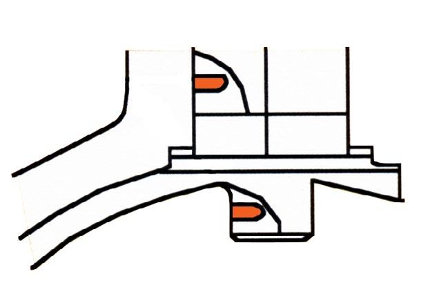
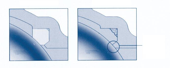
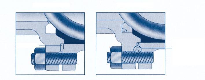
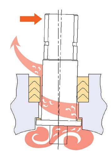
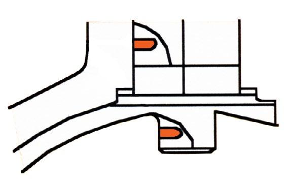
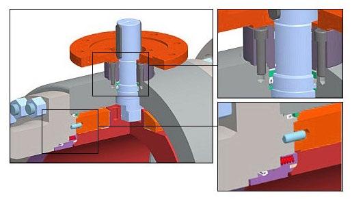
• CONTACT BETWEEN STEM AND VALVE SHELL
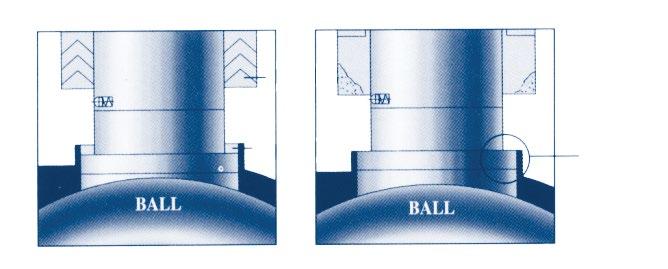
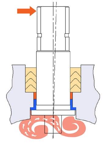
• CONTACT BETWEEN BALL AND VALVE SHELL
•
CERTIFIED
Australian Pipeline Valve ball valves are designed and built to meet stringent specifications for anti-static protection.
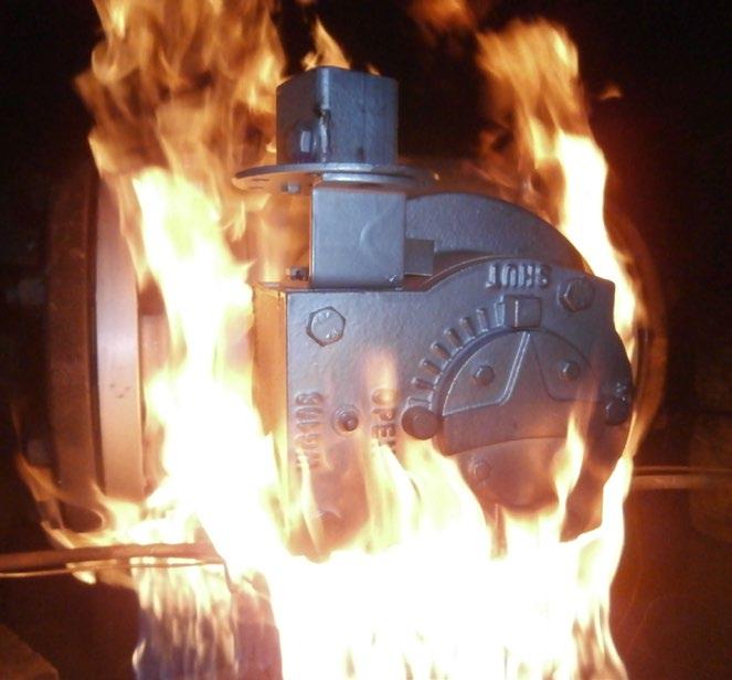
One of the many requirements of today’s industries is that ball valves must have a metal to metal seal in case the non-metallic seals are destroyed or burned by fire or other means.
The design provides assurance to the user handling flammable or hazardous fluids should the non-metallic seals be damaged.
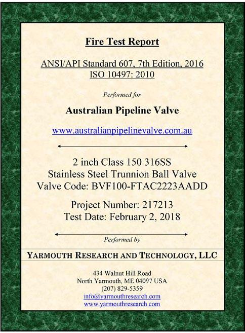
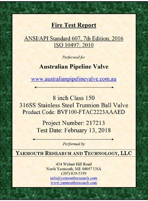
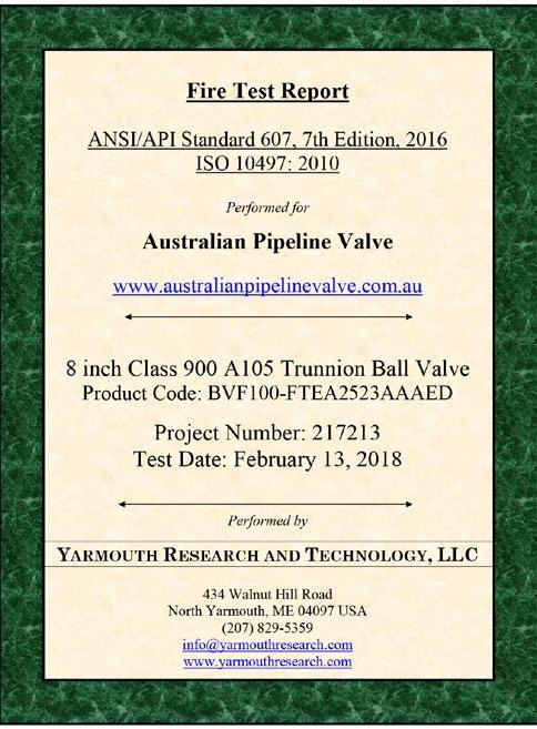
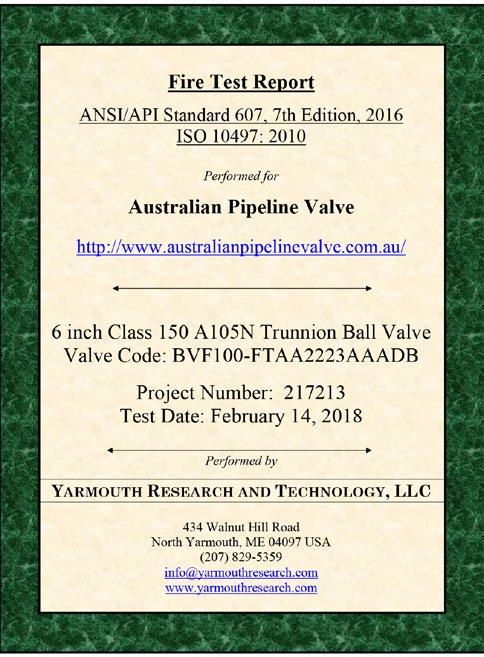
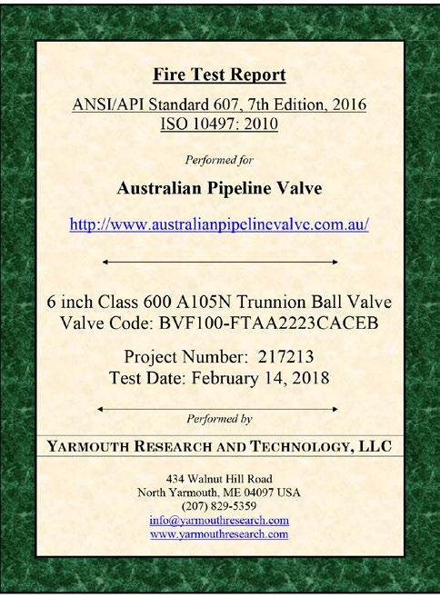
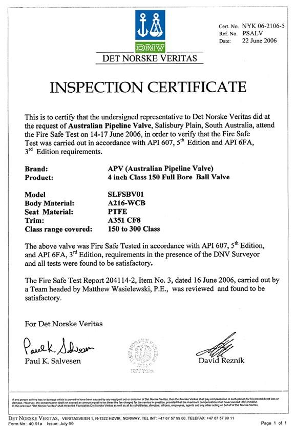
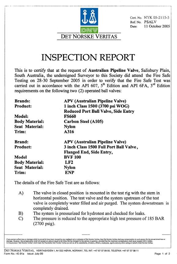
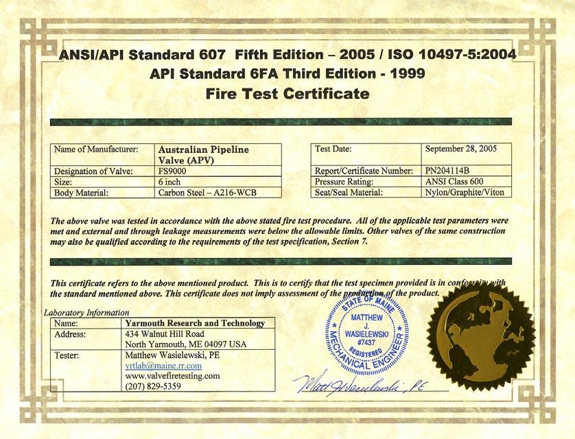
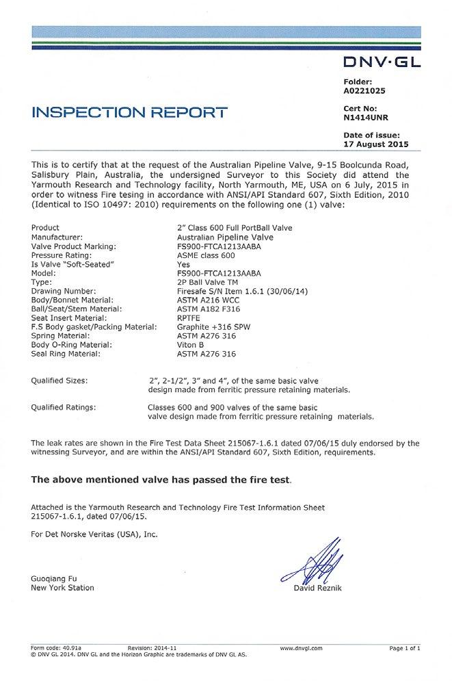
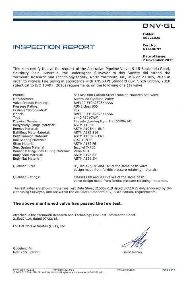
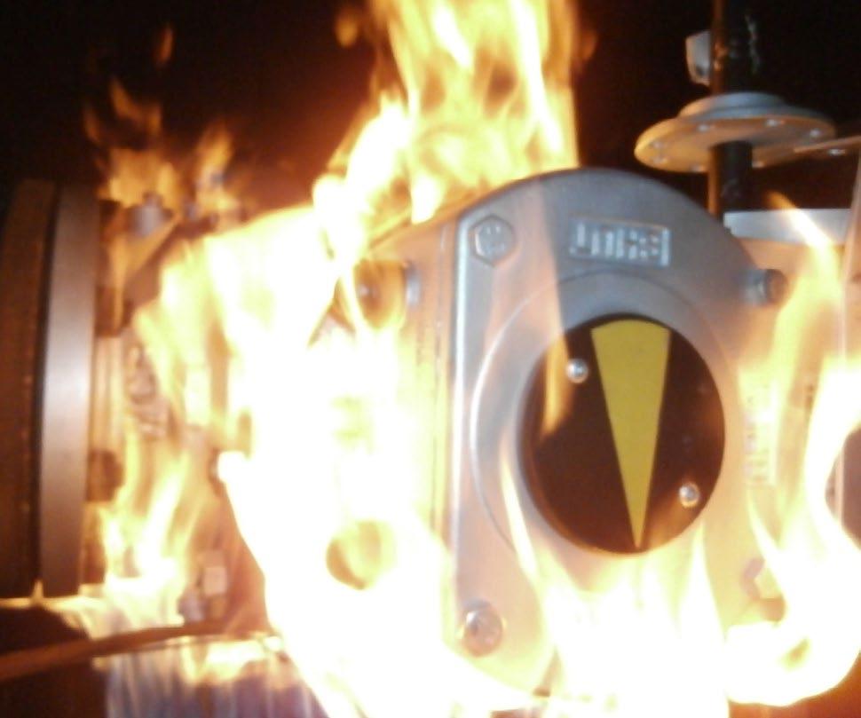
Australian Pipeline Valve was one of the first brands in the world to obtain Firesafe certification (DNV witnessed) to the 7th edition of API 607, ISO 10497.
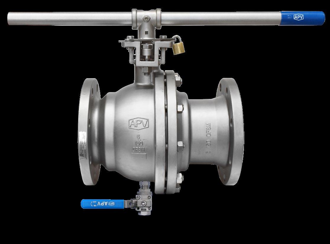
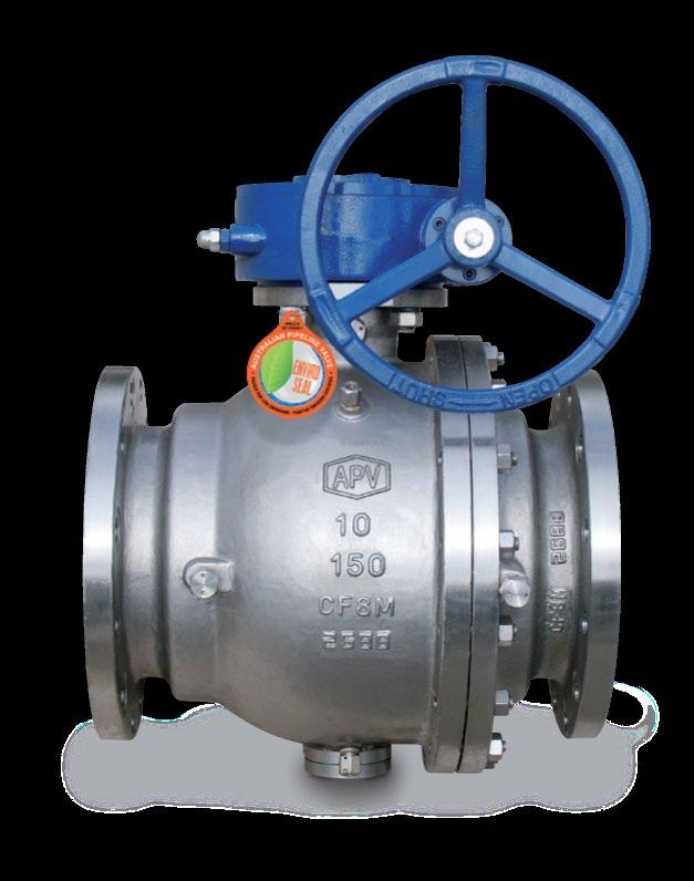
ASTM A351 - CF8M & CF8 AND ASTM A216 - WCB NACE MR0175 (CLASS III BOLTING) FOR SOUR SERVICE
ISO 5211 TOP flange for Actuation (most sizes)
• API 6D & API 608
• 10” & over trunnion mounted *
• Full bore solid ball
• Split Body 2 piece design
• Anti Blow-Out Stem
• Anti-Static Device
• Firesafe Design to API 607 and API 6FA
• Temperature Range -29°C to 230°C
• Sealant injection facility & body drain available on request
• Also available in metal seats and PEEK seats
• Also available in Monel, Duplex, Alloy20 etc.
* 10” 150 avaliable in floating and trunnion
1 Body *4
2 Nut *3 ASTM A194
3
4 Cap *4
5
6
7
8 Thrust Washer PTFE PTFE PTFE
9
* 1 Also available in “PEEK” or CPTFE for high temperature
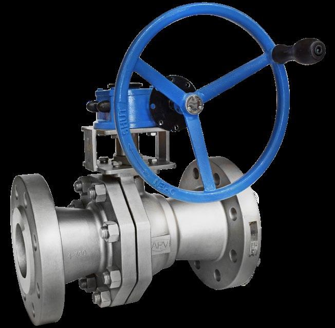
* 2 Gear operator: 250NB 300# & over; 300 NB 150# & over
* 3 NACE class 1 or II on request
* 4 Also available in Forged
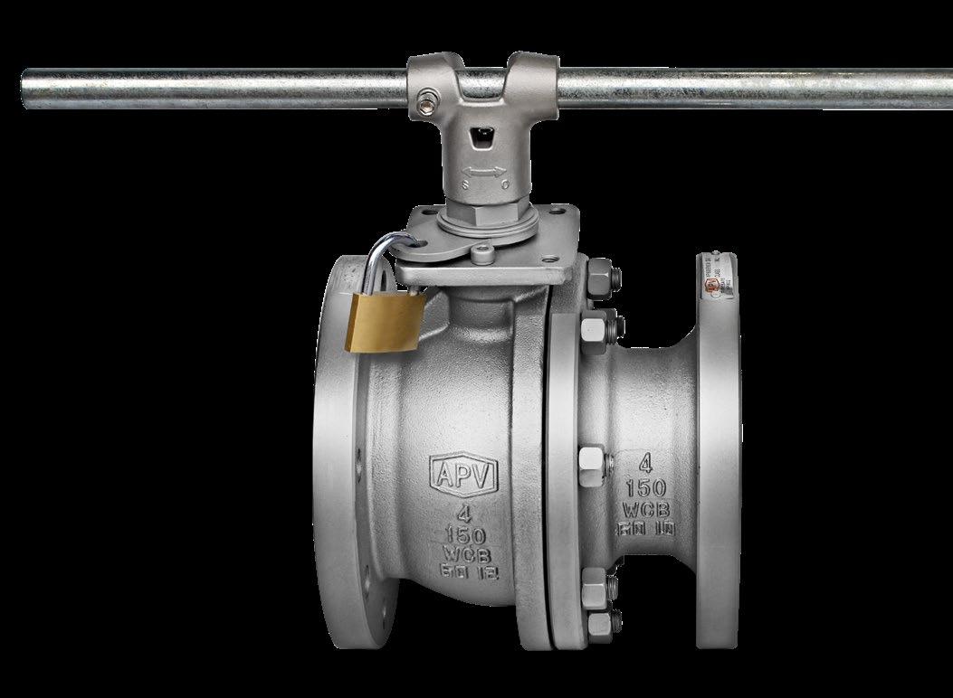
* 5 Locking Device Optional
* 6 Gland Nut can be yoke type as shown and unibolt and belleville spring depending on size/class


Gasket is designed so that the outer circumference of the gasket is in metal to metal contact with the valve body flange.
The seat is carefully designed for perfect sealing at low and high pressure ranges, as well as for minimised operating torque. If the seat ring is burnt, the ball is pressed against the metal body by fluid pressure, effecting a seal. For double block & bleed service the seat is energised against the ball to allow double block & bleed. The energised seat will ensure the first seat seals against the ball in both directions, at low & high pressure.
DIMENSIONS ANSI-150LB
Torque is maximum breakaway at maximum differential (running torque is approx 1/3 of breakaway). A 20% factor is included,
DIMENSIONS ANSI-300LB
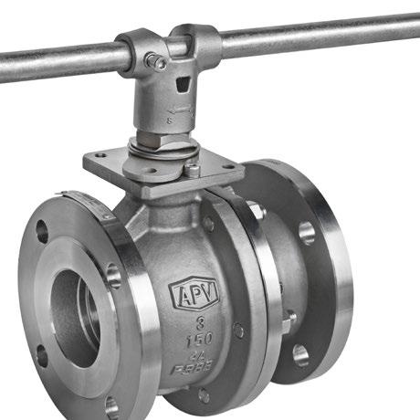
ASTM A351 - CF8M & CF8 AND ASTM A216 - WCB
NACE MR0175 FOR SOUR SERVICE
ISO 5211 TOP flange for Actuation (optional)
• API 6D & API 608
• AGA approved for AS 4617, AS 4629.1 & AS 4629.2
• Reduced bore*, solid ball
• Investment Cast or Forged
• Uni Body 1 piece design
• Anti Blow-Out Stem
• Anti-Static Device
• Firesafe Design to API 607 and ISO 10497
• Temperature Range -25°C to 230°C
• Also available in metal seats and PEEK seats
• Also available in Monel, Duplex, Alloy 20 etc.
*Full bore available up to 25NB (1”)
No. Part Name Stainless Steel CF8M Carbon Steel
1 Body (4) ASTM A351 Gr. CF8M ASTM A216 Gr. WCB
2 Gland Yoke (7) ASTM A351 Gr. CF8M A216 Gr. WCB
2A Gland Nut/Bolt (7) ASTM A194 Gr. 8 ASTM A194 2H
2B Gland Retainer (7) AISI 316 AISI 304 AISI 304
2C Gland Bolt (7) ASTM A193 Gr. B8 ASTM A193 B7 ASTM Gr. B8
3 Screw AISI 316 AISI 304 A2 Stainless
3A Snap Ring (3) ASTM A276 Gr. 304 ASTM A276 Gr. 304 ASTM A276 Gr. 304
4 Cap (4) ASTM A351 Gr. CF8M ASTM A216 Gr. WCB ASTM A351 Gr. CF8
5 Body Gasket PTFE Graphoil / Spiral PTFE
5A Body Seal (6) Graphite Graphite Graphite
6 Ball ASTM A351 Gr. CF8M ASTM
7 Seat (1)
8 Thrust Washer PTFE PTFE PTFE
9 Stem (8)
(1) Also available in “PEEK” or CPTFE for high temperature (2) Gear operator: ≥200NB 300# and ≥250NB 150# (3) Design depends on size & class (4) Also available in Forged (5) Locking device optional (6) Or PTFE if non firesafe (7) Gland (2) can be uni-nut (2A) as shown or yoke type depending on size and class (8) Stem smoothness Ra 0.2 0.6 µm (superior to API requirements) (9) Stuffing box smoothness ≤Ra 1.6 µm (superior to API requirements) (10) Chesterton 1622 FE packing


Gasket is behind a threaded metal to metal end closure. The SLFSBV02 can be supplied elastomer free for chemical or higher temperature applications.
The seat is carefully designed for perfect sealing at low and high pressure ranges, as well as for minimised operating torque. If the seat ring is burnt, the ball is pressed against the metal body by fluid pressure, effecting a seal.
FIRESAFE CERTIFIED API 607 6TH EDITION AND IS0 10497
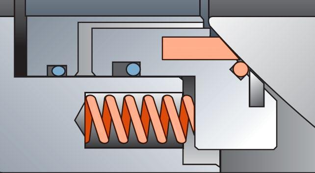
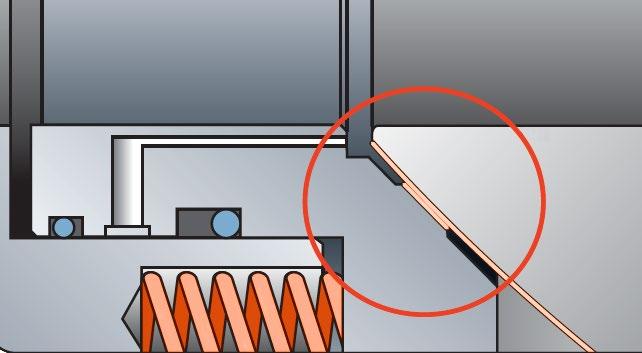
• CONTACT BETWEEN STEM AND VALVE SHELL
METAL TO METAL CONTACT BEFORE FIRE AFTER FIRE
• CONTACT BETWEEN BALL AND VALVE SHELL
METAL TO METAL CONTACT BEFORE FIRE AFTER FIRE
Blow Out Proof Stem
Internally inserted, “back seated” blow out proof stem assures fire safety and blow out prevention by retaining stem in the valve at all pressures.
Anti-Static Device
Spring loaded pins between the ball, stem and body which prevents static throughout the valve.
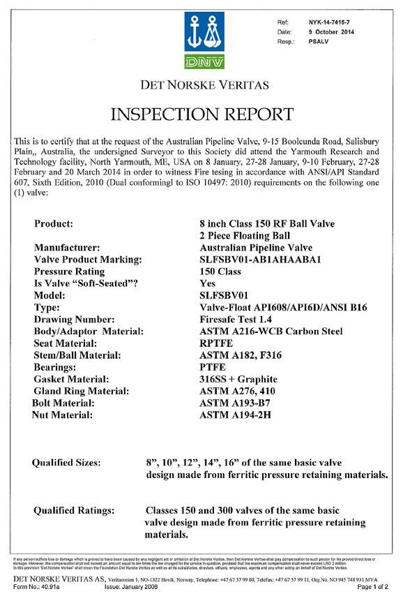
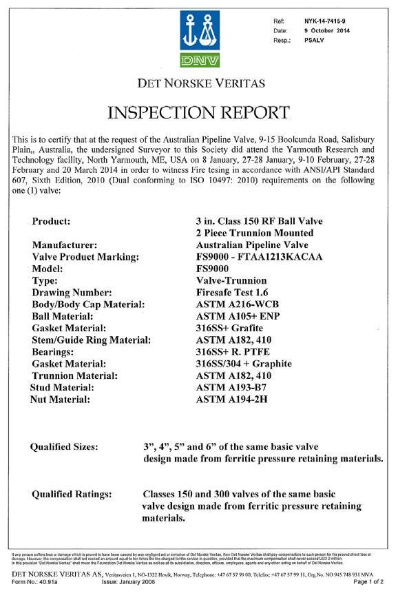
Australian Pipeline Valve was one of the first brands in the world to hold Firesafe certification (DNV witnessed) to the 6th & 7th edition of API 607 as well as ISO 10497.
Safety (Vent) Hole Pressure balanced design. Relieves the pressure differential between the body cavity and the ball port to prevent buildup of trapped pressure and to prolong the life of the stem packing/seals. (80NB & above)
Australian Pipeline Valve ball valves are designed and built to meet stringent specifications for anti-static protection.
One of the many requirements of today’s industries is that ball valves must have a metal to metal seal in case the non-metallic seals are destroyed or burned by fire or other means.
The design provides assurance to the user handling flammable or hazardous fluids should the non-metallic seals be damaged. APV ball valves are certified to meet or exceed the requirement of API 607 6th and 7th edition and ISO 10497.
A. Valve size 15A (1/2”) to 32A (1/4”)
B. Valve size 50A (2”) to 80A (3”)
C. Valve size 100A (4”) to 125A (5”)
D. Valve size 150A (6”) to 250A (10”)
Carbon PTFE will do higher temperatures
Seat design. Low and high pressure zero leakage capability. Large contact face.
Flexible design and radial grooves on sides of seats ensure upstream pressure balances cavity pressure.
SLFSBV01 (Firesafe)
SLBV01 (Non Firesafe)
SLFSBV02 (Firesafe)
SLBV02 (Non Firesafe)
SLFSBV01-DBB (Firesafe) -V suffix (V-Port)
A Class 150
B Class 300
C Class 600 D Class 800
E Class 900
F Class 1500
G Class 2500
K AS/BS Table E
L AS/BS Table F
M AS/BS Table H
Special
Operation
Bare Stem
Lever Handle
Gear Operator
Special
For metal seat see separate part number system in the ‘Special Service Ball Valves Catalogue’.
Inconel
1/2” - 36” ANSI CLASS - 150/300/600/900/1500/2500
Design and construction conforms to API 6D specifications, tested to API 607 & 6D standards.
Independent loaded upstream and downstream seats provide a tight shut-off and allow the valves to be used for bi-directional flow. Spring loaded seat design provides low and high pressure sealing and body cavity pressure relief due to self relieving seat design.
Suitable for single or double block and bleed applications.
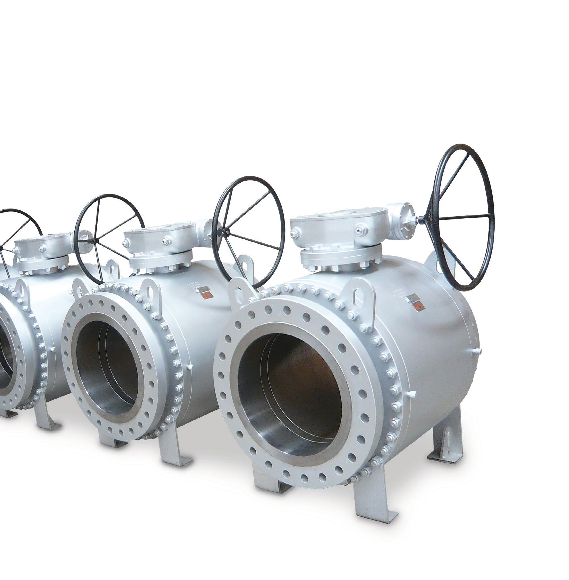
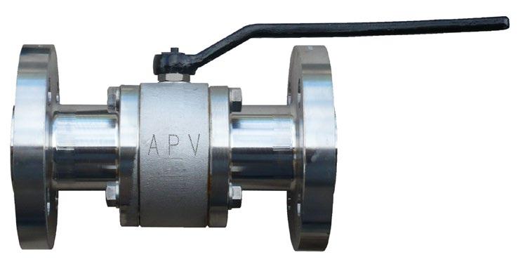
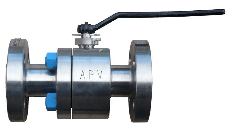
BVF100 Series 3 Piece Ball Valves have an emergency seal facility, blow-out proof stem, full through-conduit bore, electroless nickel plated or stainless trim and are anti-static. Stem and gland seals can be replaced in-line for ease of maintenance.
Available with locking devices, stem extensions, pipe pups, and actuation.
The full range of APV valves can meet NACE standard MR-10-75, latest edition if necessary.
APV was one of the first brands in the world to have firesafe certification to API 607 6th and 7th Edition, as well as being Firesafe Certified (DNV witnessed) to API 6FA 3rd Edition & ISO 10497-2010.
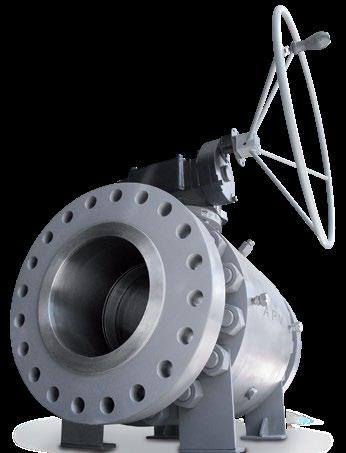
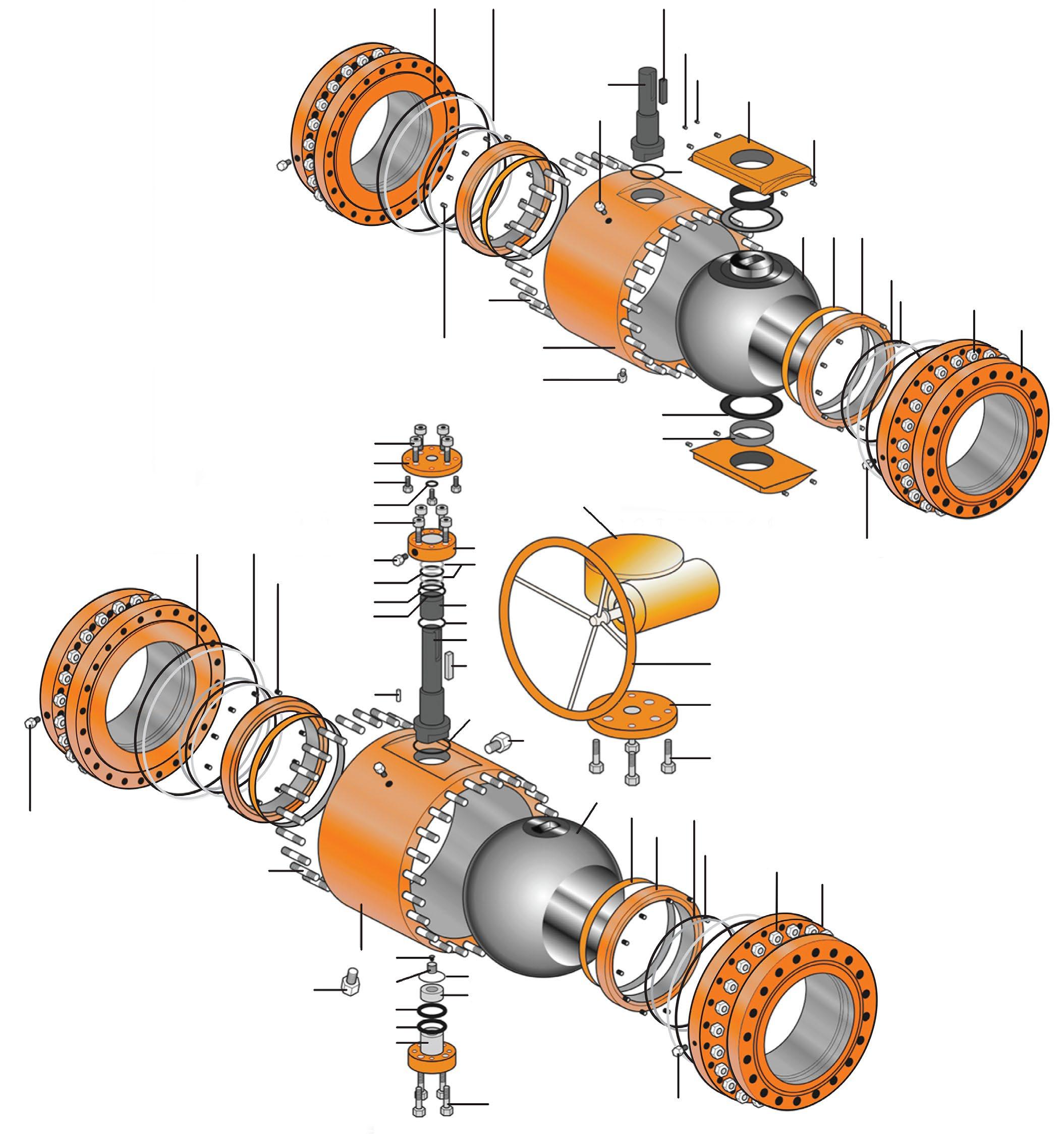
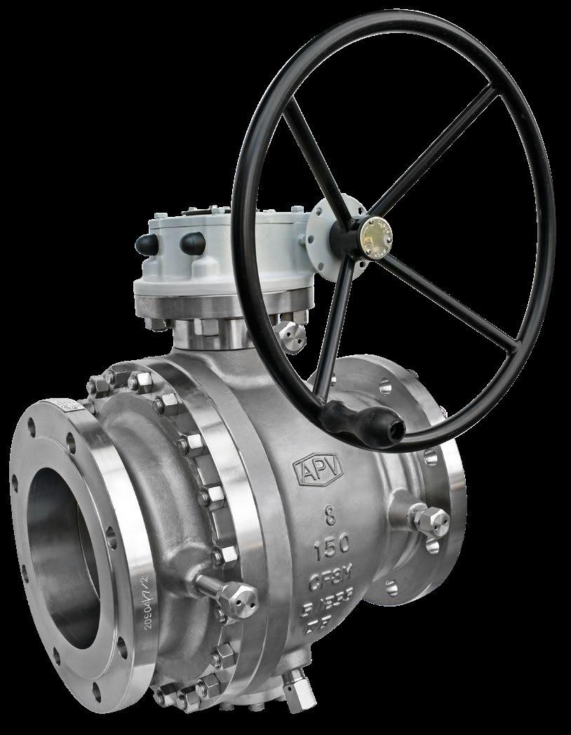
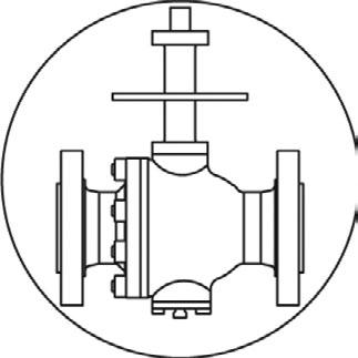
FEATURES
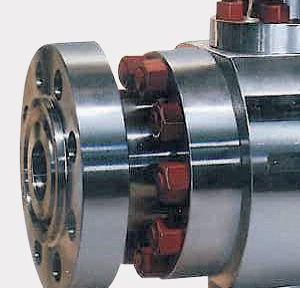
• Forged Construction
• Rugged Anti-Corrosive Gear Design
• Seat Lubrication Facility
• Body Bleed and Drain Ports
• Enclosed, Encapsulated Triple Barrier Stem Seals
• Blowout Proof Stem Design
• Emergency Stem Lubrication Fitting
• Self Lubricating PTFE coated Trunnion Bearings
FIRESAFE CERTIFIED API 607 5TH, 6TH & 7TH
EDITION AND API 6FA 3RD EDITION
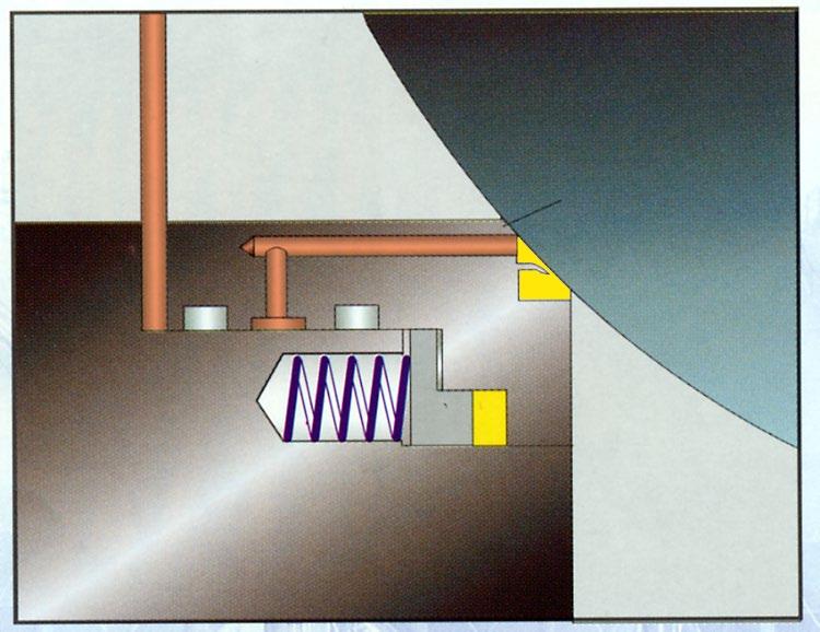
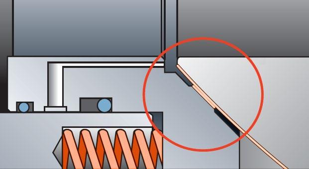
When non-metal sealing materials are decomposed or deteriorated by a plant fire, the edge of the metal seat retainer preloaded by the seat spring comes into contact with the ball to provide metal to metal shut off of the line fluid to minimise internal leakage through the valve bore. APV ball valves are also antistatic design
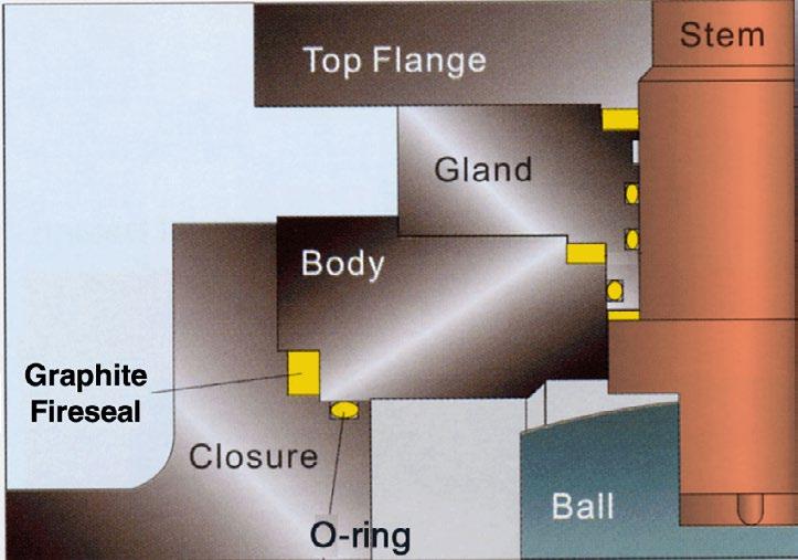
Leakage from the valve stem area is prevented by double sealing with 2 O-rings and a graphite gland gasket. Leakage through the valve body joint is also prevented by double sealing with elastomer O-ring and graphite body gasket. After a fire has deteriorated the O-rings, the graphite gland gasket, body gasket and stem seals are the measure that prevents external fluid leakage.
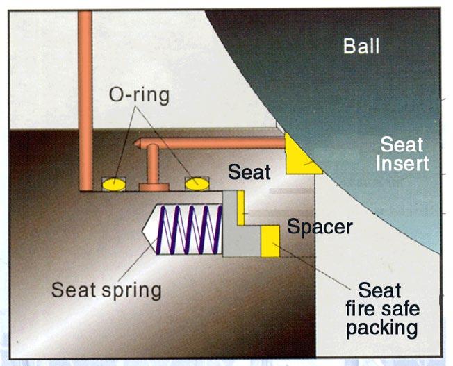
When non-metal materials such as O-ring, seat insert and spacer are decomposed or deteriorated by fire, the edge of the metal seat preloaded by the seat spring comes into contact with the Ball to shut off the line fluid to minimise internal leakage through the valve bore. Also the fire safe flexible graphite seat area packing will be compressed by the seat spring to prevent fluid leakage between the valve body and the seat.
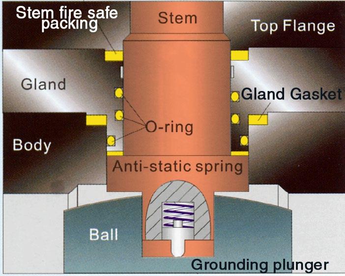
The stem is separate from the ball. The lower end of the stem is designed with an integral collar to be blowout-proof.
Antistatic device is a standard feature of APV ball valve. A spring-loaded pin assures the electrical continuity, between ball, stem and body, so as to avoid sparks during turning of the stem to open and close the valve, which could be dangerous in case of hazardous area installation.
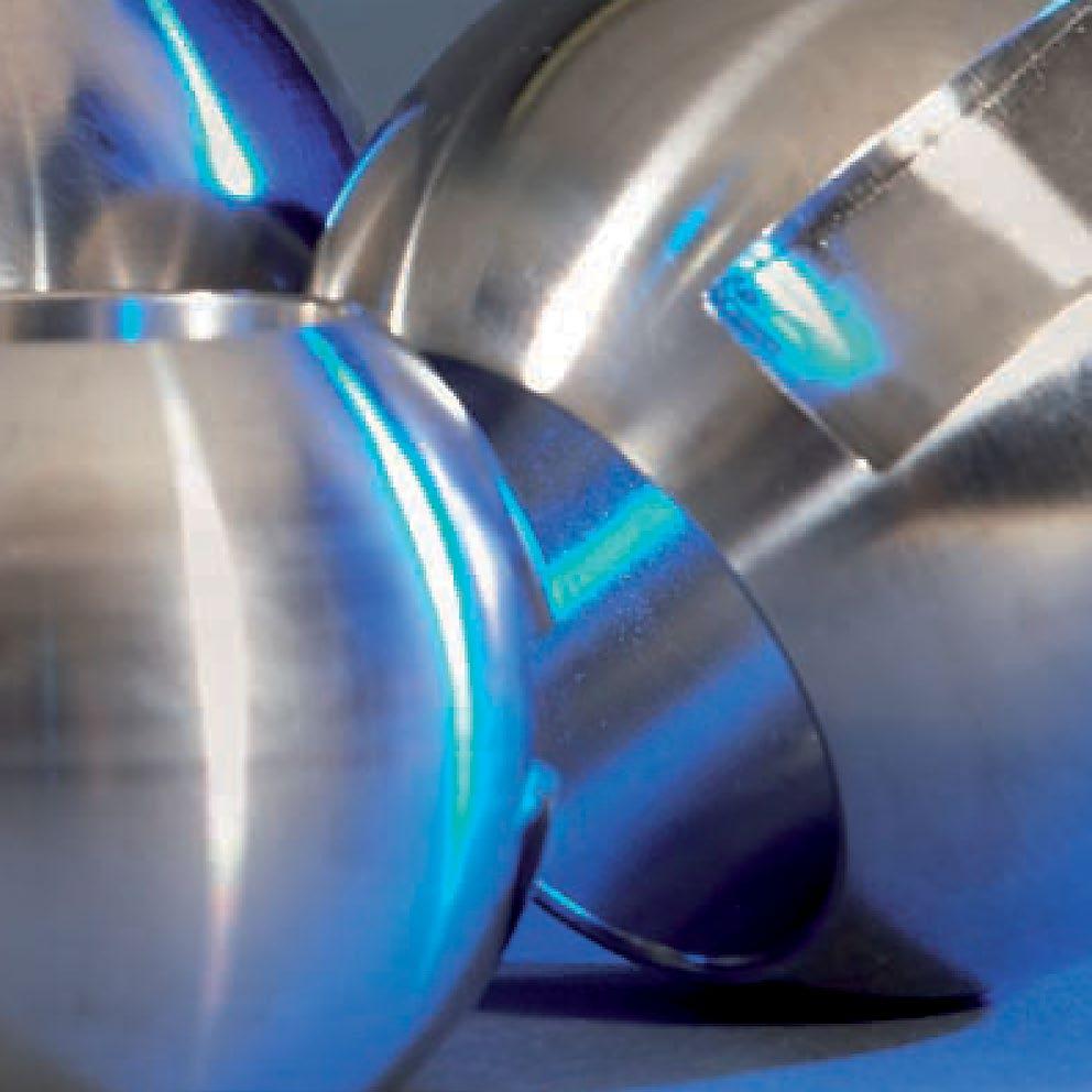
APV CONVENTIONAL SOFT SEAT INSERT
APV seat inserts can be ordered in a variety of materials whilst still complying to API seat test requirements for “bubble-tight shut off” for oil & gas applications as well as specialised fluid transmission applications in chemical and mining sectors.
APV CONVENTIONAL SOFT SEAT INSERT + SCRAPER
The A-PMSS+S® design is the same as the A-PMSS® above except for the addition of a scraper. On conventional trunnion ball valve seating systems, APV offers the PR-A-PMSS+S® seat design option (8” and above). A protective scraper ring is inserted in front of the soft seat insert to remove solid particles, dirt or debris that could damage or clog the contact area between ball and soft seat insert ring. This feature assures that the working area of the seat will be clean allowing the seats to work effectively. This design prolongs seat life whilst only minimally increasing cost & is particuarly advantageous for valves that cannot be removed from the line for repair such as buttweld valves, welded body valves, buried service valves as well as known non clean service applications.
APV COMPOSITE SEAL SEAT SYSTEM
APV Double or Triple seal seat design is ideal for applications that require redundant sealing when start up conditions are known to have debris in the line and where removing the valve is not possible. This design offers lower torque and superior low pressure shut-off whilst providing zero leakage reliability at an affordable price compared to metal seated. Multiple material types are employed for each seal providing a combination of resilient and superhard properties to deal with a wide range of entrained particulates and debris. Even if one or even two of the seals are damaged an effective seal can usually be maintained.
APV has extensive experience in the supply of valves for applications such as high temperature corrosive and/or erosive/abrasive environments. Various hard face material can be employed on the ball and seat face. Refer to the APV Special Service Ball Valve Catalogue.
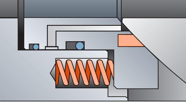
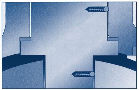
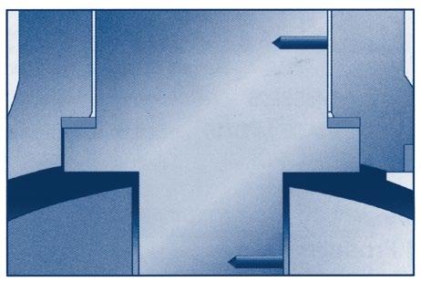
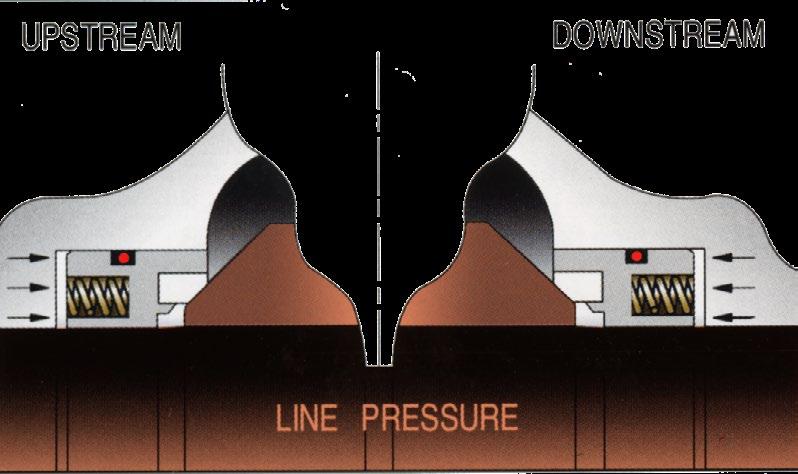
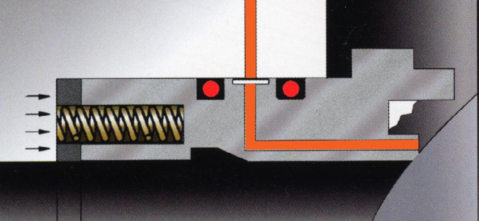
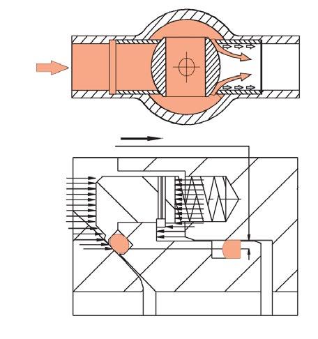
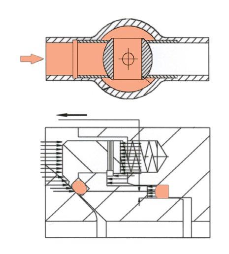
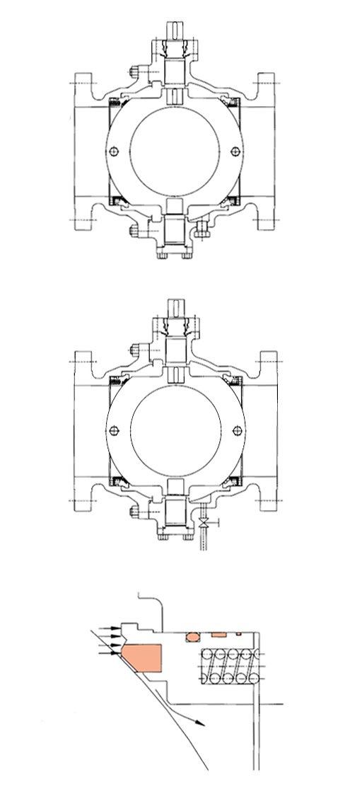
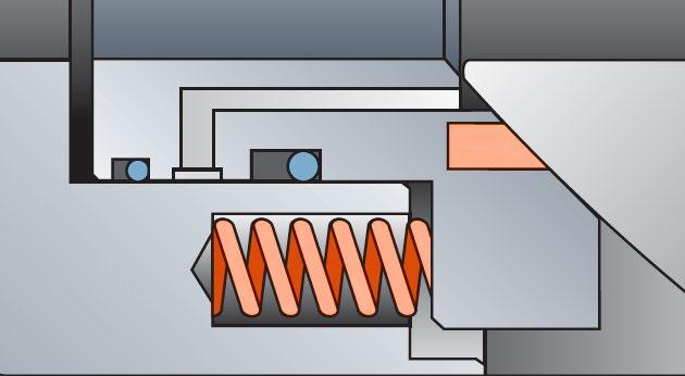
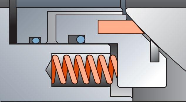
APV piston-action seats are floating type & allow the automatic relief of excess pressure from the body to the pipeline. The helical seat springs that provide a uniform initial low pressure seat sealing load against the ball are fully enclosed in individual housings. Independent floating spring loaded seats are always in contact with ball to provide an effective tight seal even at low differential pressures. Independent upstream & downstream seats permit draining of fluid from the body cavity, allowing double block & bleed operation. With the single sealing feature, when the valve is closed there is an automatic body cavity release of over pressure to the line through the downstream seat. The pre-tightened seat springs are preset to automatically relieve excess cavity pressure caused by thermal expansion down stream once pressure exceeds the API 6D (6.8) maximum (1.33 times the valve pressure rating at 38°C at the time of publishing this catalogue)
A combination of double sealing features on the downstream side and single sealing on the upstream seat is available on request. This configuration maintains the sealing capacity of the valve in case of failure of the up stream seat and release of the body cavity over pressure through the up stream seat.
As line pressure increases the seat reacts to the force of the pressure to form an effective seal. In the absence of line pressure, coil springs around the seat unit provide a tight seal by keeping the seat in contact with the ball.
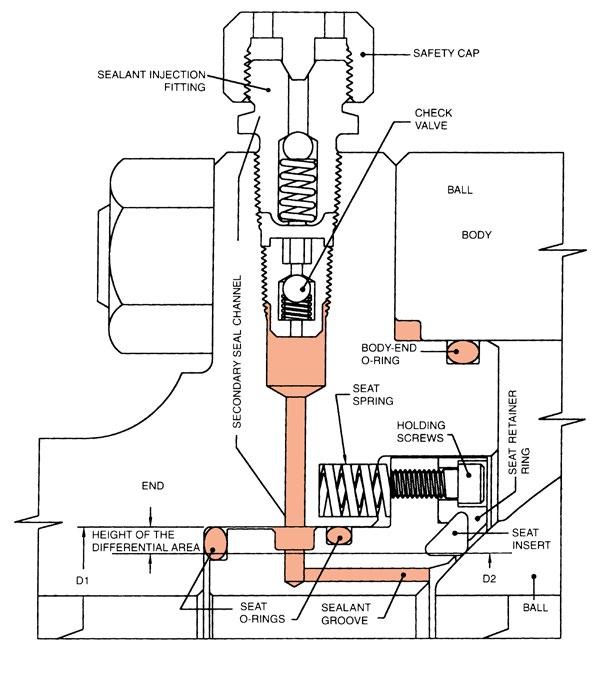
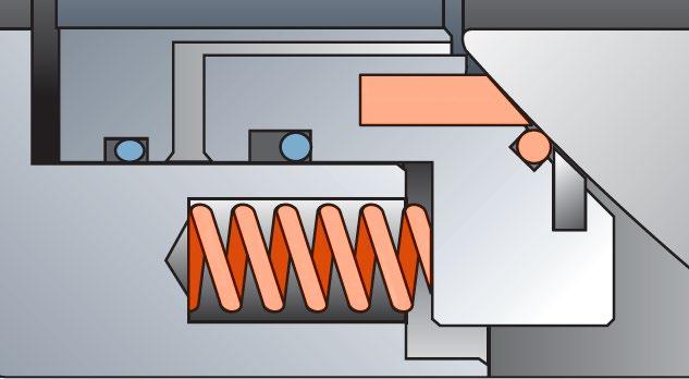
APV ball valves ordinarily require no lubrication. Configuration shows a secondary temporary sealing mechanism to inject sealant directly to the seats in case the seats are ever damaged by foreign matters or in event of an accident.
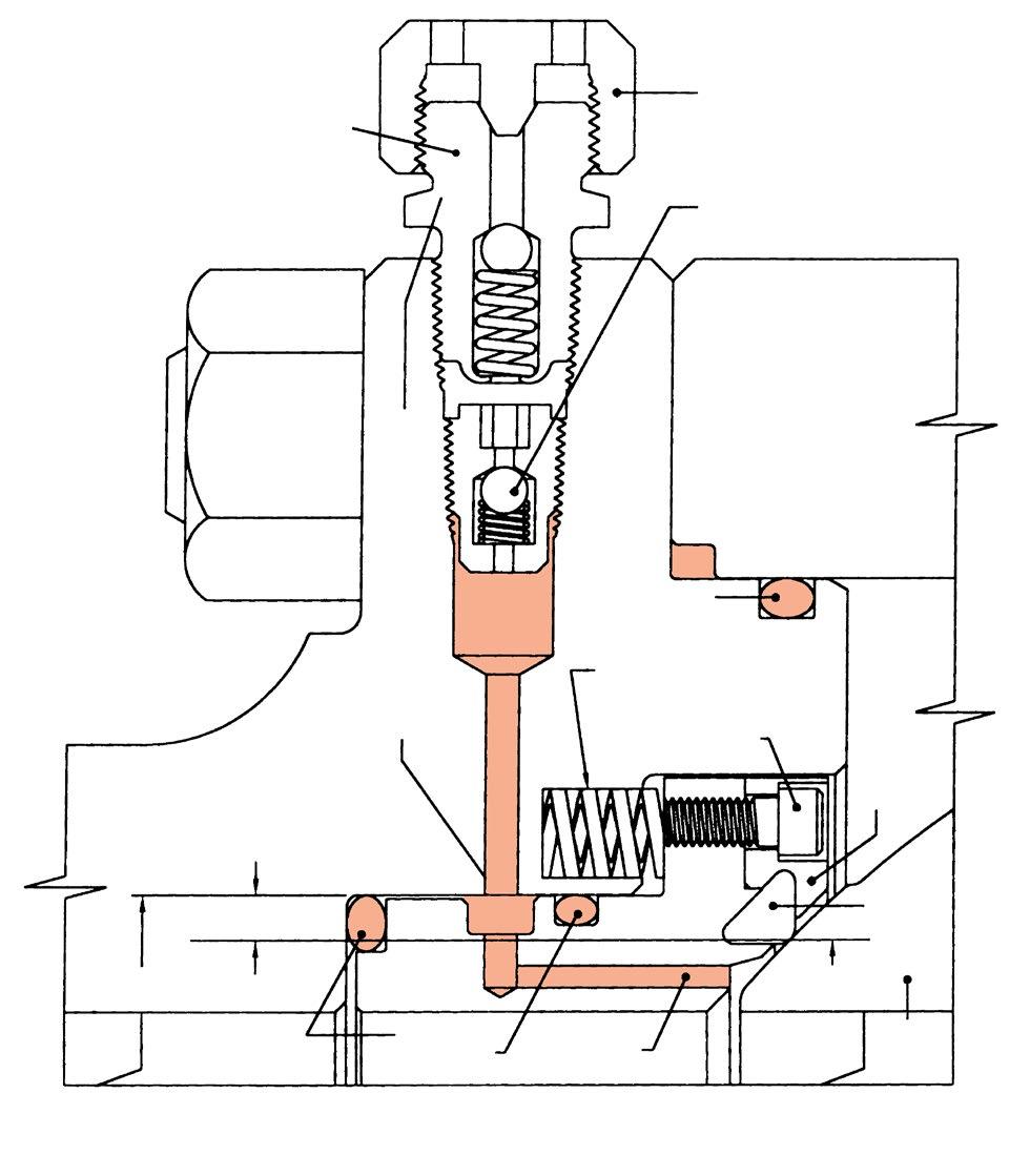
Cross-Section Seat Sealant Injection System (design varies according to size and class)
As line pressure increases the seat reacts to the force of the pressure to form an effective seal. In the absence of line pressure, coil springs behind the seat provide a tight seal by keeping the seat in contact with the ball surface. Independent floating spring loaded seats are always in contact with the ball to provide an effective tight seal even at low differential pressure. Independent upstream and downstream seats permit draining of fluid from the body cavity, so allowing double block & bleed operation (closed position only). With the optional single sealing feature, there is automatic body cavity release of over pressure to the line through the down stream seat.
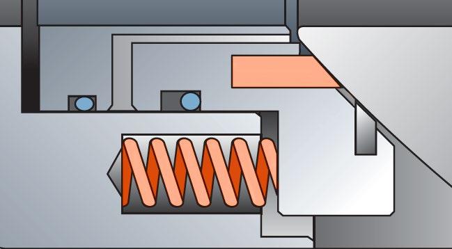
In self relieving condition, excessive internal body pressure is automatically relieved both upstream & downstream into the line by excessive pressure forcing the seats away from the ball.
With the ‘DPE’ seat option, if a leakage occurs in the upstream seat, the pressure entering the body cavity pushes the downstream seat against the ball & valve seals. Line pressure forces a seal against the floating seat.
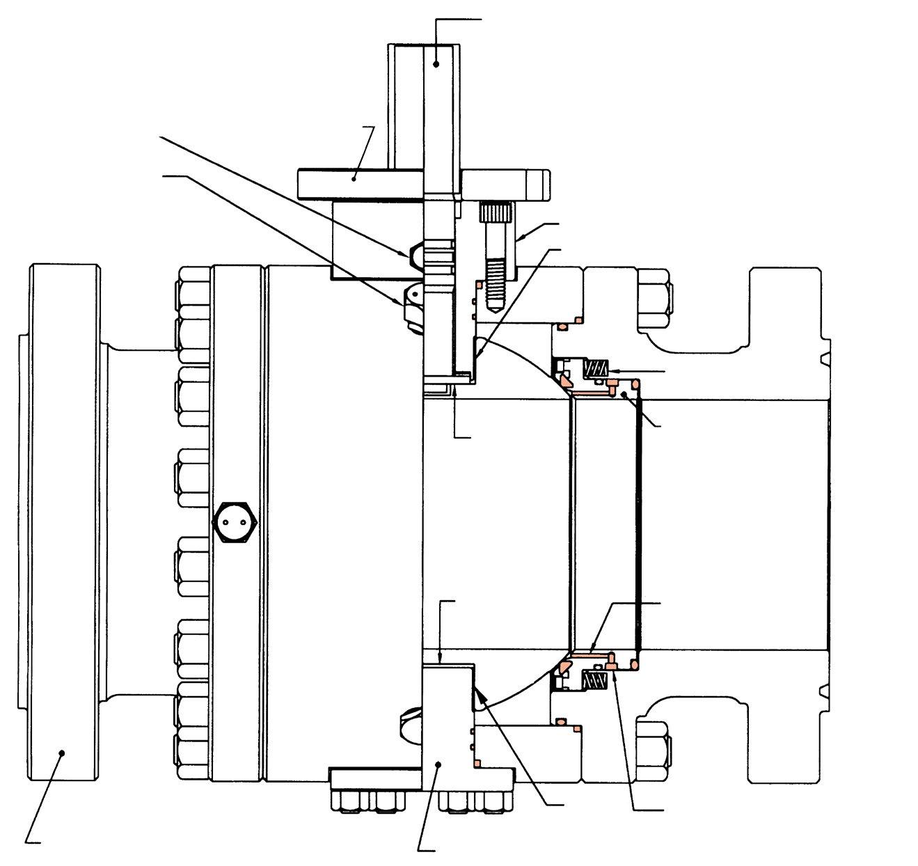
Leakage from the stem area is prevented by double barrier sealing with O-Rings as well as graphite fireseals. Leakage through the valve body joint is also protected by double sealing with an O-Ring and a flexible graphite gasket. After a fire has deteriorated the O-Rings, graphite packing and secondary seal ensure prevention of external fluid leakage.
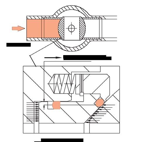
Whether in the open or closed position, pressure on each side of the ball is blocked from the body cavity by the seat ring. The cavity can be blown down or drained (only in closed position) through the body port to indicate line isolation is effective.
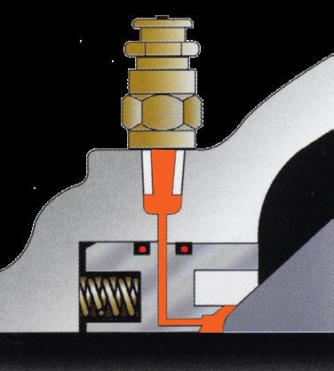
In case of fluid leaks from the seat or stem sealing area, a sealant can be supplied through the injection fitting to temporarily prevent leakage.
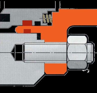
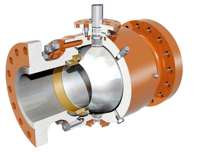
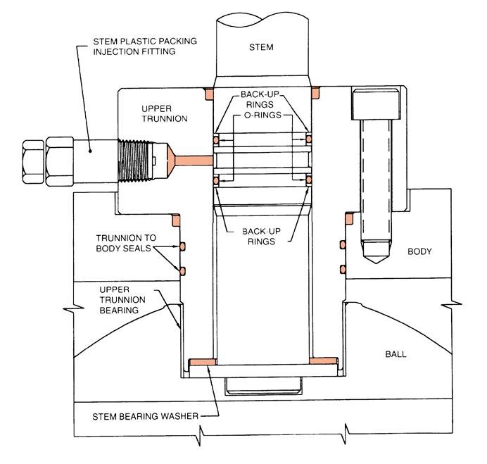
The main stem seal is formed using two O-rings protected by two back-up rings to avoid extrusion. The design of the stem seal allows for the injection of plastic packing or grease sealant to form an emergency seal.
The stem bearing washer and the upper and lower trunnion bearings are made from reinforced teflon with a stainless steel backing. This assures a low friction coefficient and high corrosion resistance.
Cross-Section Stem Sealant Injection System
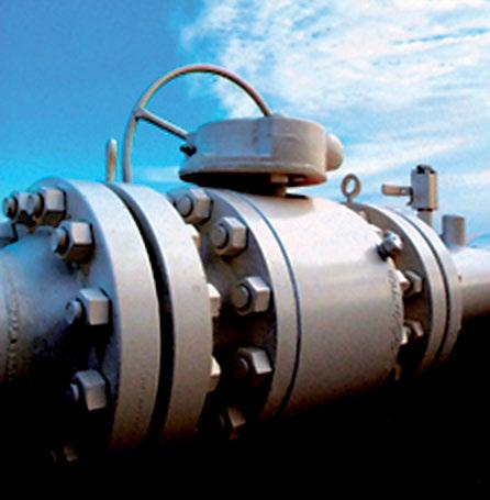
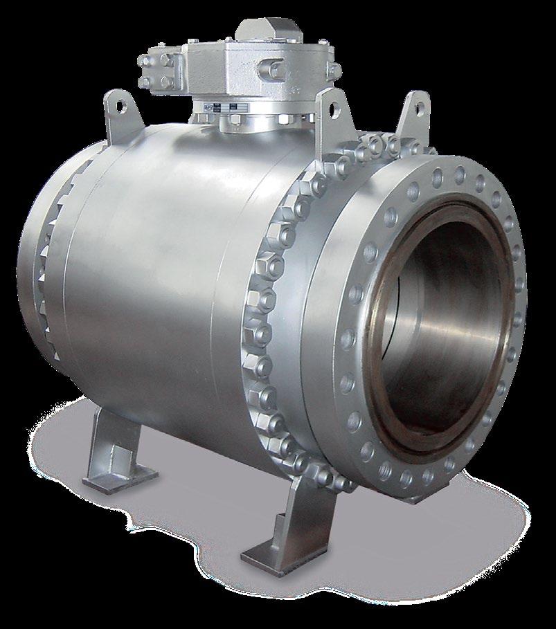
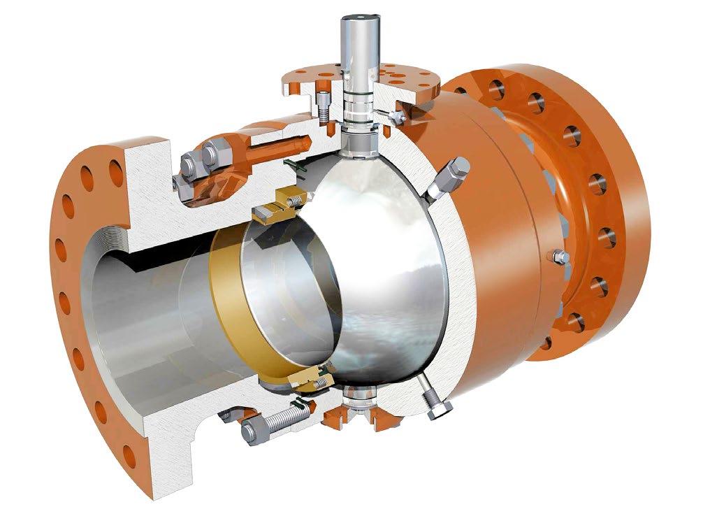
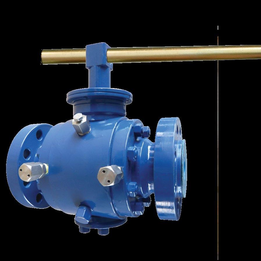
FLANGED / BW ENDS API 6D
• API 6D
• Flanged & Butt weld ends
• 3P split body, side entry
• Trunnion mounted ball, low operating torque
• Fire safe API 607, ISO 10497
• Anti-static device, BS 5351
• Double block & bleed
• Pressure self relieving seats
• Self Lubricating PTFE coated Trunnion Bearings
OPERATING CONDITION
Operating Temperature
-29ºC~+185ºC*
Pressure Rating
PN 20, 50, 64, 100, 150
Class 150, 300, 400, 600, 900, 1500, 2500
* Low and high temperature service also available
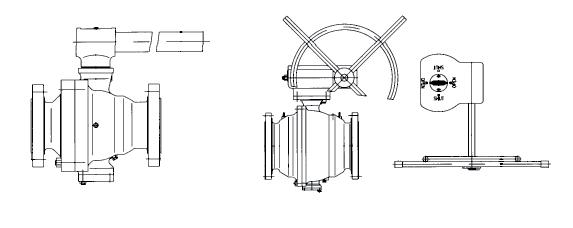
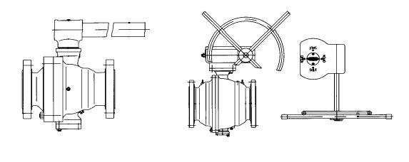
Conventional Trunnion Design
6
Lever Operated
Gear Operated
* Lever Operator **30x24 & 36x30 refer to drawing. Notes:- Sizes 1/2” to 1-1/2”, 2-1/2” & 5” also available, drawing on request. Short pattern design also available in larger sizes.
Lever Operated
Gear Operated
Lever Operated
Gear Operated
* Lever Operator
Notes:- Sizes 1/2” to 1-1/2” also available, drawing on request.
Lever Operated
Gear Operated
* Lever Operator Note:- Sizes 1/2” to 1-1/2” also available, drawing on request
* Lever Operator
Note:- Sizes 1/2” to 1-1/2” also available, drawing on request Lever Operated Gear Operated
2
2
3
4
* Lever Operator
3000 PSI
* Lever Operator
Lever Operated
Gear Operated
* Lever Operator
Lever Operated
Gear Operated
* Lever Operator
Note:- Sizes 1/2” to 1-1/2” also available, drawing on request
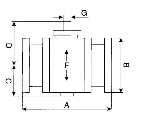
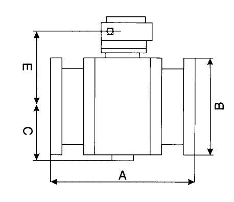
Flanges in accordance with ANSI B16.5
Welding ends according to ANSI B16.25
Bore sizes (F) according to API 6D
End to end dimensions according to API 6D or 6D4
Approximate weights
Lever operated - as shown*
9Special 1PTFE 2RPTFE 3 Graphite 4Metal 5Other
or equivalent.
A Raised Face*
B Ring Joint C Butt Weld DThreaded
E Socket Weld
F RF Flanged X B/W
H Unmachined RF/RJ
ZSpecial
A Bare Stem
B Lever Handle
CGear Operator
D Locking Lever
E Locking Gear Op. ZSpecial
316 Stainless B 304 Stainless C A105 + ENP D LF2 + ENP E F51 / S31803 F 17-4 PH SS J 4140 + ENP K 410/F6A Stainless LF55 Duplex ZSpecial
A 316 Stainless
B 304 Stainless
C A105/F52+ENP* .075mm
D LF2+ENP* .075mm
E Duplex F51 S31803
FInconel G Alloy 20
HHastelloy
K 410/F6 Stainless
LDuplex F55
M 4140 + ENP*
ZSpecial
/ Seat Retainer * ≤ 500Hv hardness.
AB7
BB7M
C B8
DB8M
E Duplex
F L7
GL7M
HB16
ZSpecial
1/2”-36”


API TRUNNION MOUNTED BALL VALVE MANUFACTURING SPECIFICATIONS
Specification Standards
General
Pressure-temperature
Flange type and dimensions
Butt-weld ends
6D
B16.34
B16.10
B16.5
B16.25
Inspection and test API 6D/API 598
TRUNNION MOUNTED BALL VALVE DESIGN FEATURES
STREAM SEALING TWO-WAY VALVE
The up-stream seal of the valve is effected by the advanced spring pre-tightening seats which automatically adjust. The twoway valve has two seats that can be sealed in both directions, so there’s no limitation of flow direction during installation.
BLOCK & BLEED VALVE
Being “up-stream side sealing”, the valve can bleed out the trapped fluid in the body cavity when the valves is in fully open or fully close position. The fluid is intercepted by seats on up stream and down stream side.
As line pressure increase the seat reacts to the force of the pressure to form an effective seal. In the absence of line pressure, coil springs around the seat unit provide a tight seal by keeping the seat in contact with the ball.
The stem packing or O-ring may be replaced under working pressure. Bleeding the dirty fluid periodically can reduce damage of the sealing surface and prolong the service life of the valve.
If the pressure of the body cavity unusually increases due to thermal expansion, APV ball valves automatically relieve the pressure by compressing the spring in the spring pre-tightening seat package. The excess pressure will then be relieved back downstream.
Optional seat designs can be specified to relieve pressure only back upstream or in the case of Double Piston effect seals (DPE). Pressure can be relieved to atmosphere via an external body relief valve.
Full bore and reduced bore are available in all sizes. Full bore is full through conduit bore size to API 6D to facilitate pigging operations.
When the seat and / or stem sealing system is damaged, the grease injection valve can inject sealant into the valve for temporary sealing.
Two O-rings are utilised in the stem area for reliable performance, as well as a graphite fireseal. STEM SEALING SYSTEM
Under normal circumstances Australian Pipeline Valve valves require no lubrication.
FLEXIBLE OPERATION
The seat and stem bearing has a Teflon coating which is low friction and self-lubricates to reduce the valve operation torque.
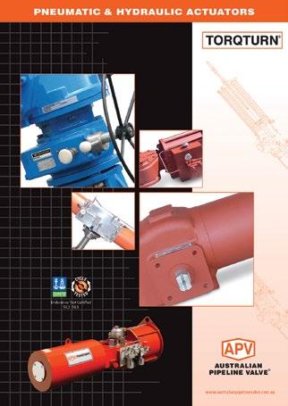
The valve may be operated by hand, pneumatic operator, motor, hydro-pneumatic operator and hydraulic operator, etc.
Stem extensions for underground service applications can also be fitted.
TRUNNION BEARINGS
Self lubricating PTFE coated trunnion bearings top and bottom.
The full range of APV valves can meet NACE standard MR-10-75, latest edition if necessary.
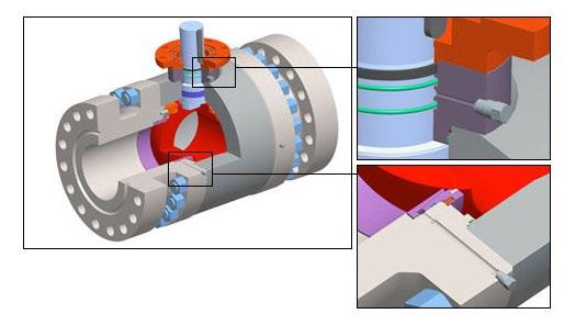
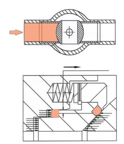
Cross-Section Seat Area
Cross-Section Stem Area*
*Design will vary depending on size & class
FIRESAFE CERTIFIED API 607 5TH & 6TH
EDITION AND API 6FA 3RD EDITION
When non-metal sealing materials are decomposed or deteriorated by a plant fire, the edge of the metal seat retainer preloaded by the seat spring comes into contact with the ball to provide metal to metal shut off of the line fluid to minimise internal leakage through the valve bore. APV ball valves are also antistatic design
Leakage from the valve stem area is prevented by double sealing with 2 O-rings and a graphite gland gasket. Leakage through the valve body joint is also prevented by double sealing with elastomer O-ring and graphite body gasket. After a fire has deteriorated the O-rings, the graphite gland gasket, body gasket and stem seals are the measure that prevents external fluid leakage.
When non-metal materials such as O-ring, seat insert and spacer are decomposed or deteriorated by fire, the edge of the metal seat preloaded by the seat spring comes into contact with the Ball to shut off the line fluid to minimise internal leakage through the valve bore. Also the fire safe flexible graphite seat area packing will be compressed by the seat spring to prevent fluid leakage between the valve body and the seat.
The stem is seperate from the ball. The lower end of the stem is designed with an integral collar to be blowout-proof.
Antistatic device is a standard feature of APV ball valve. A spring-loaded pin assures the electrical continuity, between ball, stem and body, so as to avoid sparks during turning of the stem to open and close the valve, which could be dangerous in case of hazardous area installation.
APV seat inserts can be ordered in a variety of materials whilst still complying to API seat test requirements for “bubble-tight shut off” for oil & gas applications as well as specialised fluid transmission applications in chemical and mining sectors.
CONVENTIONAL
The A-PMSS+S® design is the same as the A-PMSS® above except for the addition of a scraper. On conventional trunnion ball valve seating systems, APV offers the PR-A-PMSS+S® seat design option (8” and above). A protective scraper ring is inserted in front of the soft seat insert to remove solid particles, dirt or debris that could damage or clog the contact area between ball and soft seat insert ring. This feature assures that the working area of the seat will be clean allowing the seats to work effectively. This design prolongs seat life whilst only minimally increasing cost and is particuarly advantageous for valves that cannot be removed from the line for repair such as buttweld valves, welded body valves, buried service valves as well as known non clean service applications.
COMPOSITE
APV Double or Triple seal seat design is ideal for applications that require redundant sealing when start up conditions are known to have debris in the line and where removing the valve is not possible. This design offers lower torque and superior low pressure shut-off whilst providing zero leakage reliability at an affordable price compared to metal seated. Multiple material types are employed for each seal providing a combination of resilient and superhard properties to deal with a wide range of entrained particulates and debris. Even if one or even two of the seals are damaged an effective seal can usually be maintained.
APV has extensive experience in the supply of valves for applications such as high temperature corrosive and/or erosive/abrasive environments. Various hard face material can be employed on the ball and seat face. Refer to the APV Special Service Ball Valve Catalogue.
As line pressure increases the seat reacts to the force of the pressure to form an effective seal. In the absence of line pressure, coil springs behind the seat provide a tight seal by keeping the seat in contact with the ball surface. Independent floating spring loaded seats are always in contact with the ball to provide an effective tight seal even at low differential pressure. Independent upstream and downstream seats permit draining of fluid from the body cavity, so allowing double block & bleed operation (closed position only). With the optional single sealing feature, there is automatic body cavity release of over pressure to the line through the down stream seat.
In self relieving condition, excessive internal body pressure is automatically relieved both upstream & downstream into the line by excessive pressure forcing the seats away from the ball.
With the ‘DPE’ seat option, if a leakage occurs in the upstream seat, the pressure entering the body cavity pushes the downstream seat against the ball & valve seals. Line pressure forces a seal against the floating seat.
Leakage from the stem area is prevented by double barrier sealing with O-Rings as well as graphite fireseals. Leakage through the valve body joint is also protected by double sealing with an O-Ring and a flexible graphite gasket. After a fire has deteriorated the O-Rings, graphite packing and secondary seal ensure prevention of external fluid leakage.
Whether in the open or closed position, pressure on each side of the ball is blocked from the body cavity by the seat ring. The cavity can be blown down or drained (only in closed position) through the body port to indicate line isolation is effective.
In case of fluid leaks from the seat or stem sealing area, a sealant can be supplied through the injection fitting to temporarily prevent leakage.
Body
Packing Support
Ball
A216-WCB A216-WCB A351-CF8, CF3 A351-CF8M,CF3M A352-LCB, LCC
A105-1025 A102-1025
A105+ENP .003” A182-316
A182-F304,F304L A182-F316, F316L A182-F304
A182-F304, F304L* A182-F304,316L* A182-F304 or F316
A216-WCB+ENP .003” A182-316 A351-CF8, CF3* A351-CF8M, CF3M* A352-LCB, LCC+.003”ENP
Stem A182-F6a 316 or 17-PH
A182-F304, F304L A182-F316 ,F316L A182-F304 or 316
Seals PTFE / PEEK (PPL) / Nylon
Seating Retainer A105-1025+ENP .003” 316 A182-F304, F304L A182-F316, F316L A182-F304 or F316
Packing
PTFE / PEEK (PPL) / Graphite
Gasket PTFE / PEEK (PPL) / Graphite
Bearings PTFE / PEEK (PPL) / 316+PTFE
Spring INCONEL X750
* ENP or hard chrome surfacing for smoothness and hardness in some sizes and classes
Remarks All materials conform to ASTM standard.
We can provide alternative body and trim materials according to valve working conditions or customer’s requirements. We also reserve the rights to improve the valve material according to relative standard.
Stud A193-B7 A193-B7M A193-B8, B8M A193-B8, B8M A320-L7M Nut A194-2H A194-2HM A194-8, 8M A194-8, 8M A194-7ML O-Rings Viton B / Buna / Viton AED / Viton GLT / Elast-O-Lion® 985 / Aflas PRESSURE/TEMPERATURE SOFT SEAT
The P-T rating is not only governed by the body material, but is further defined by the material of seat, packing and gasket. The selection of sealing material is dependant upon the medium passing through valve, valve working temperature, pressure and velocity of flow. As the P-T rating varies according to different valve working conditions, the following P-T rating value is calculated assuming stable valve working condition.
CLASS 150 DIMENSIONS mm (Flange dimensions refer to ASME B16.5 CLASS 150)
Note:- Sizes 1/2” to 1-1/2” also available. (2 Piece Forged). Short pattern design also available.
Note:- Sizes 1/2” to 1-1/2” also available. (2 Piece Forged). Short pattern design also available.
Note:- Sizes 1/2” to 1-1/2” also available. (2 Piece Forged)
CLASS 600 DIMENSIONS mm (Flange dimensions refer to ASME B16.5 CLASS 600)
Note:- Sizes 1/2” to 1-1/2” also available. (2 Piece Forged)
CLASS 900 DIMENSIONS mm (Flange dimensions refer to ASME B16.5 CLASS 900)
Note:- Sizes 1/2” to 1-1/2” also available. (2 Piece Forged)
CLASS 1500 DIMENSIONS mm (Flange dimensions refer to ASME B16.5 CLASS 1500)
Note:- Sizes 1/2” to 1-1/2” also
(2 Piece Forged)
* Internal Trunnion design shown available 150NB (6”) and
A352-LCB/LF2+ ENP
5 Seat Insert
/ Nylon / Devlon / POM
/ Nylon / Devlon / POM
/ Nylon / Devlon / POM 6
A276-410 ENP/F6A/316
20 Trunnion Bearing A182 F316+PTFE
23 Plug ASTM A576-1025 + ZP
A276-316
24 Springs Inconel X750 Inconel X750 Inconel X750
25 O-Ring
Viton B/Viton AED/HNBR Viton B/Viton AED/HNBR/Aflas HNBR/Elast-O-Lion 985/Viton GLT
26 O-Ring Viton B/Viton AED/HNBR Viton B/Viton AED/HNBR/Aflas HNBR/Elast-O-Lion 985/Viton GLT
27 O-Ring Viton B/Viton AED/HNBR Viton B/Viton AED/HNBR/Aflas HNBR/Elast-O-Lion 985/Viton GLT
28 O-Ring
29 O-Ring
30 Stud
31 Nut
32 Screw
33 Bolt
Viton B/Viton AED/HNBR
Viton B/Viton AED/HNBR
ASTM A193-B7 + ZP
Viton B/Viton AED/HNBR/Aflas HNBR/Elast-O-Lion 985/Viton GLT
Viton B/Viton AED/HNBR/Aflas HNBR/Elast-O-Lion 985/Viton GLT
ASTM A193-B7M + ZP ASTM A193-B8/B8M
ASTM A194-2H + ZP
ASTM A194-2HM + ZP
ASTM A194-2H + ZP
ASTM A194-2HM + ZP
ASTM A194-2H + ZP
ASTM A194-2HM + ZP
34 Pin ASTM A576-1045
35 Key
36 Injection Fitting Assembly
A576-1045
ASTM A194-8/8M
ASTM A193-B8/B8M
ASTM A193-B8/B8M
A276-304/316
A276-304/316
ASTM A350-L7 + ZP
ASTM A320-L7M + ZP
ASTM A194-4 + ZP
ASTM A194-7M + ZP
ASTM A320-L7 + ZP
ASTM A320-L7M + ZP
ASTM A320-L7 + ZP
ASTN A320-L7M + ZP
A276-304
A276-304
Packing Stem
*Internal trunnion designs available 150NB (6”) and over
Packing Stem
Adaptor Plate Stem
*Internal trunnion designs available 150NB (6”) and over
Adaptor plate
bearing
/ 531803
DThreaded
F RF Flanged x B/W
H Unmachined RF / RJ
ZSpecial
E Locking Gear Op. ZSpecial
A 316 Stainless
B 304 Stainless
C A105N+ENP .075mm*
D LF2+ENP .075mm*
E Duplex F51
FInconel
G Alloy 20
HHastelloy
K 410/F6 Stainless
L Duplex F55/A890 6A ZSpecial
AB7
BB7M
C B8
DB8M
E Duplex
F L7
GL7M
HB16
ZSpecial
Australian Pipeline Valve don’t consider in our design the following factors of risk:
1. Australian Pipeline Valve ‘Standard’ ball valves can be used in a temperature range between -28.8 to +200°C. (Note, pressure limitations apply above 38°C refer to Pressure/Temperature charts.) For service temperatures below -28.8°C ball valve construction materials shall be submitted to an impact test at the minimum service temperature. For temperatures outside of the range of -28.8°C to +200°C ball valves have to be provided with seats, seals and body material able to withstand the temperature degree required.
2. The onus is on the customer to specify all materials of construction and service conditions. Australian Pipeline Valve shall assume standard materials and conditions if not otherwise specified.
3. Australian Pipeline Valve ‘Standard’ ball valves are not equipped with devices suitable to avoid internal over-pressures caused by incorrect operations of process or by-fluids & liquids subjected to an increase of volume and/or pressure (these devices, such as the over-pressure hole in the ball or safety seats are available upon request).
4. Australian Pipeline Valve ‘Standard’ ball valves are not designed with special devices to withstand a sudden thermal jump (thermal shock).
5. In general Australian Pipeline Valve ‘Standard’ ball valves are not mechanically designed to bear overloads due to exceptional atmospheric or natural phenomenon’s (such as earthquakes).
6. In general Australian Pipeline Valve ‘Standard’ ball valves are not designed to bear loads on flanges, on pipe connections or pipeline.
7. In general Australian Pipeline Valve ‘Standard’ ball valves can’t withstand ice inside their bodies (in this case user must specify the optional stem extension for insulating, avoiding the presence of residual product inside the valve).
8. Australian Pipeline Valve ‘Standard’ ball valves are not suitable for low temperature service below -29°C (-20°F) unless provided with cryogenic stem extension and other modifications (available on request).
9. Australian Pipeline Valve ‘Standard’ ball valves are suitable for ‘industrial’ oxygen (not medical) service when supplied degreased and packed in polyethylene bags only.
10. The compatibility between ball valves construction materials and medium is selected by the user. The user is ultimately responsible for verifying the compatibility between medium and materials.
11. Abrasive or dirty service, high temperature service, low temperature service, vacuum service, near zero pressure service and other special applications should be clearly stated when requesting quotation.
Before installing the ball valve onto the pipe-line it is mandatory for the user to verify the compatibility of the ball valve with service conditions (medium, temperature and pressure). With reference to standard ball valves held in stock the reseller and end user will have to assure themselves of the compatibility with the use of conditions required by the customer. Australian Pipeline Valve ball valves must be only used for on-off (fully open/fully closed) service.
Before using the ball valve in a potential explosive atmosphere it’s necessary: -
• To verify the compatibility between the ball valve and the zone in which the ball valve should be installed.
• To foresee the pipe-line ground condition on which the ball valve should be installed.
• To check that the temperature of the ball valve surface is not higher than the flammable point of the atmosphere in which the ball valve is installed (in this case specify an insulating cover device for the valve and an extension for the wrench)
• Before installing ball valves with welding ends to make sure that the process of welding is carried out in accordance with all the safety requirements of the classified zone.
• To avoid mechanical knocks during the installation that may cause sparks.
The APV fire safe ball valves are provided with anti-static devices for ball-stem-body. When service conditions require electrical continuity to prevent static discharge, the user is responsible for specifying static grounding.
When ball valves are to be utilised on liquids with very high velocity, check with the valve distributor or manufacturer for appropriate advice to minimise the possibility of seat deformation, especially when they are highly pressurised on high temperature line.
THROTTLING
Ball valves are generally not recommended for throttling service, as both the fluid flow and the leading edge of the ball can damage or deform the resilient ball seats causing leakage. High fluid velocity or the presence of solid particles in suspension will further reduce seat life in throttling applications.
• Do not open the bonnet or cap when bearing pressure. Valve is not equipped with pressure access device. User should check it by other method through it’s piping system.
• Do not touch the surface of the valve on high temperature.
• Not allowed for unstable fluid, otherwise specified with category III in Declaration of conformity or/and in this user manual.
• Lock design on the handle to avoid the valve operated by non-related people is optional requested by the user.
Australian Pipeline Valve cannot be held responsible for damage caused by use of the product especially if it is improper use or modified.
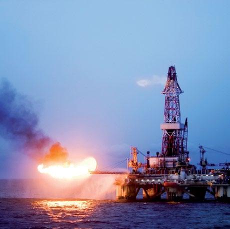
“Australian Pipeline Valve produces isolation, control and flow reversal protection products for severe and critical service media in utility, steam, pipelines, oil & gas and process industries. APV valves and pipeline products form the most competitive portfolio in the market.”