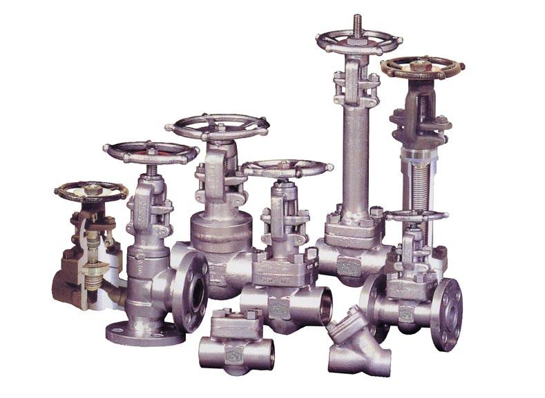
Quality is Our First Priority.
Consistent product quality and a proven track record makes Australian Pipeline Valve a dependable choice where total reliability is the number one concern.
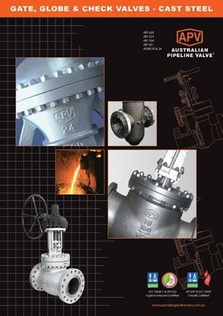
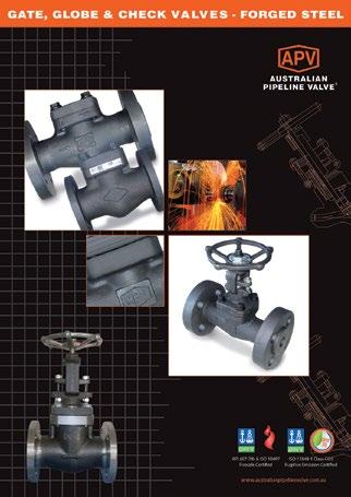
Since its founding, APV’s philosophy has been focused on quality. Our valves are manufactured in full compliance to worldwide standards (such as ASME/ANSI, API, EN, ISO, BS, AS).

(EXAMPLE) GLBBSW80ADR-E : GLOBE VALVE, BOLTED BONNET, SOCKET WELDED, 800LBS, A105N, MONEL TRIM, NON NACE, STANDARD BORE, RING GASKET
GA GATE SOLID WEDGE
GF GATE FLEX WEDGE
GP GATE PARALLEL SLIDE
GL GLOBE
GS GLOBE SDNR (STOP CHECK)
GY Y-TYPE GLOBE (IN LINE)
YS Y-TYPE GLOBE SDNR
GN NEEDLE POINT GLOBE
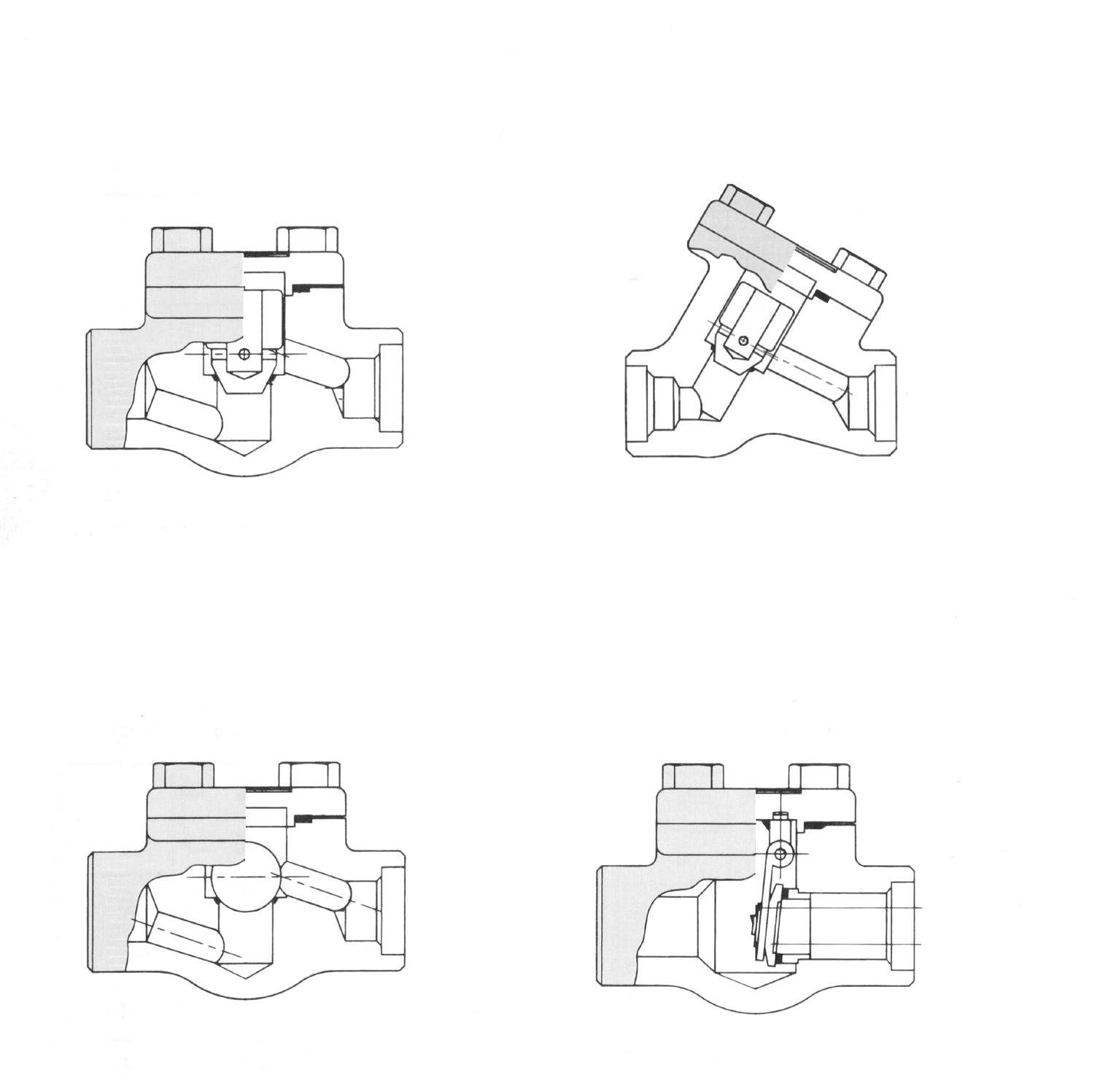
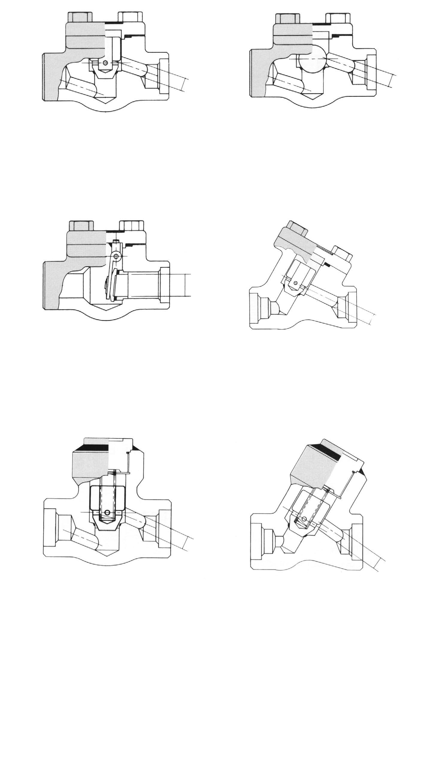
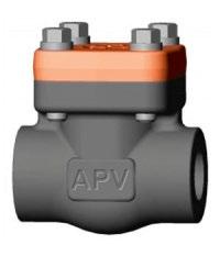
PC PISTON (LIFT) CHECK
BC BALL CHECK
HC BALL HEAD PISTON (LIFT) CHECK
SC SWING CHECK
AG RIGHT ANGLE GLOBE
AY RIGHT ANGLE GLOBE Y-TYPE
ZZ SPECIAL
B - BONNET
BB BOLTED BONNET
WB WELDED BONNET
PS PRESSURE SEAL BONNET
BL BONNETLESS
SP SPECIAL
BELLOWS SEAL/CRYOGENIC/ EXTENDED
BONNET See Section I
C - CONNECTION
NP NPT THREADED
NS NPT x SW
BS BSP THREADED
SW SOCKET WELDING
BW BUTT WELDING
RF RAISED FACE FLANGE
FF FLAT FACE FLANGE
UD UNDRILLED FLANGE
RJ RING JOINT FLANGE
RU UNMACHINED FLANGE
ZZ SPECIAL DRILLING RF/FF
15 ASME 150LBS
30 ASME 300LBS
60 ASME 600LBS
80 ASME 800LBS
90 ASME 900LBS
150 ASME 1500LBS
250 ASME 2500LBS
450 ASME 4500LBS
99 SPECIAL
A ASTM A105N
B ASTM A105
C ASTM A182-F5
D ASTM A182-F9
E ASTM A182-F11
F ASTM A182-F22
G ASTM A182-F304
H ASTM A182-F304L
J ASTM A182-F316
K ASTM A182-F316L
L ASTM A350-LF2/A105N*
M ASTM A182-F304/F304L*
N ASTM A182-F316/316L*
P ASTM A182-F321
Q ASTM A182 F51
R ASTM A182 F55
S ASTM A182 F53
T ASTM A350-LF3
Z SPECIAL *Dual Certified
Blank = NON NACE
N = NACE G -
R = STANDARD BORE
F = FULL BORE
Z = SPECIAL BORE
- = SPECIAL SUFFIX
BL = BELLOWS SEALED
CR = CRYOGENIC
EX = EXTENDED BONNET
LP = LONG PATTERN
SP = C/W SPRING
PT = PTFE SEAT
ZZ = OTHER SPECIAL
Blank Standard: Graphite.
N/A- (Check Valves)
L Live Loaded
F Fugitive Emission GRP
T PTFE
J Special
Blank Standard: SS Spiral + GRP (BB),
Pressure Seal SS or SS/GRP (PSB).
N/A- (WB)
A SS Spiral + PTFE
B S318 03 Spiral
C PTFE
D SS Spiral + PTFE + GRP
E Ring
Z Special
Material
Body Bonnet Cover
A105N
A350/LF2
A182/F1 A182/F5 A182/F9 A182/F11 A182/F22
A182/F304 A182/304L A182/F316 A182/F316L A182/F317 A182/F317L A182/F321 A182/F347
Monel Inconel Hastelloy
Stem Seat Ring * A276/410 A276/304 A276/316 A276/410 A276/304 A276/316 A276/410 A276/304 A276/316 A276/304 A276/316 A276/321 A276/317 A276/347 Monel Inconel Hastelloy
Wedge / Disc * A276/410 A276/304 A276/316 A276/410 A276/304 A276/316 A276/410 A276/304 A276/316 A276/304 A276/316 A276/321 A276/317 A276/347 Monel Inconel Hastelloy
Yoke Sleeve Bush A582-416 A582-416
Gasket
A240/316+Graphite
* + Stellite hard faced optional
A240/316+Graphite
A240/316+Graphite
A240/316+Graphite Special
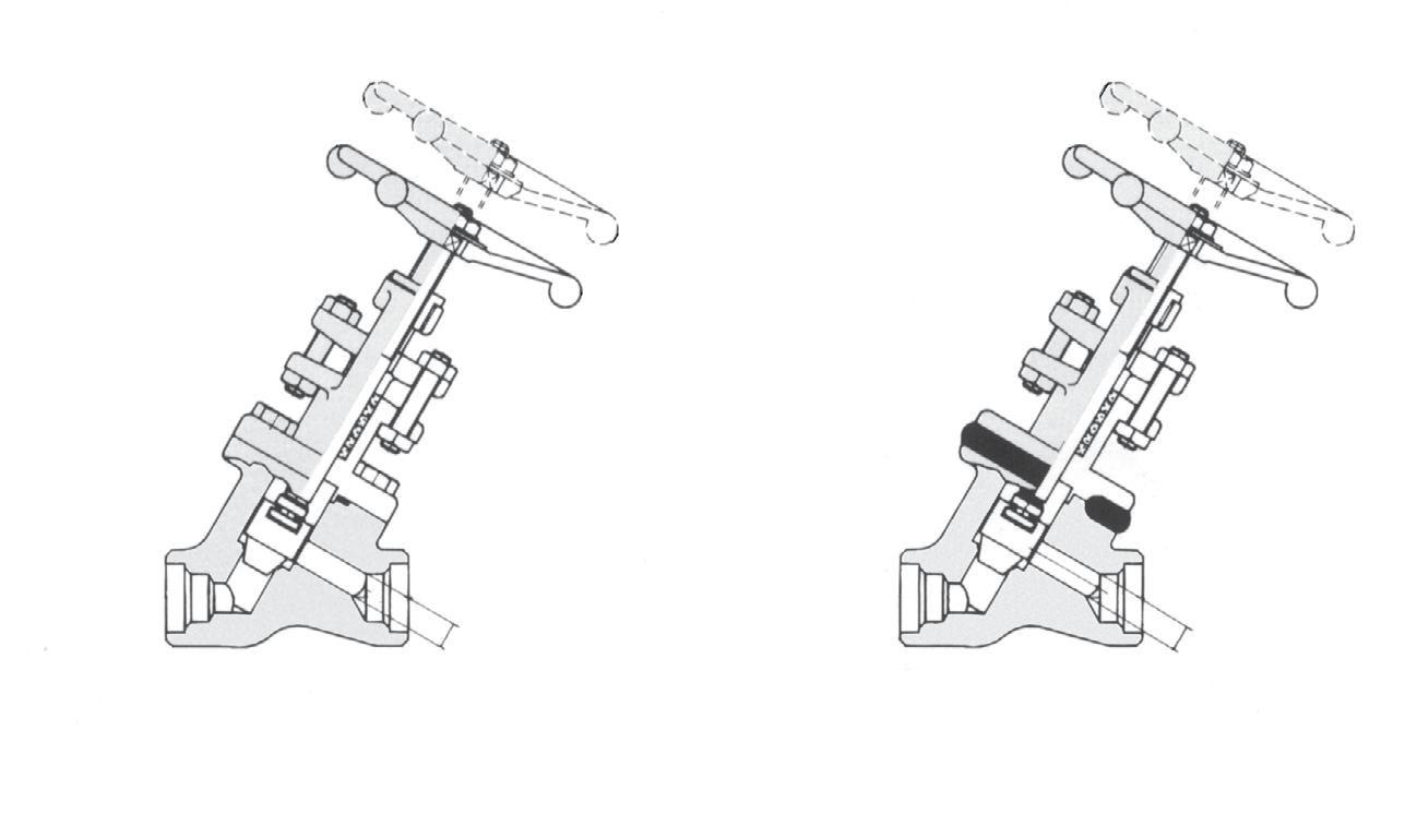
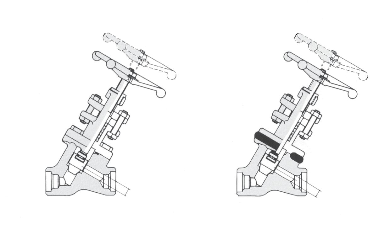
Locking device with padlock Gate & Globe Valve
Stuffing box with live loading Gate & Globe Valve
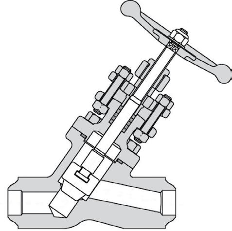
Quick opening lever Gate & Globe Valve
Pin Indicator Close Position Open Position
Position indicator - Globe Valve
• ANSI American National Standards Institute Inc.
• API American Petroleum Institute
• ASTM American Society for Testing and Materials
• BB Bolted Bonnet
• BC Bolted Cover
• BW Butt Welding
• CWP Cold Working Pressure
• EB Extended Bonnet
• FF Flat Face
• FLGD Flanged
• HF Hard Faced
Flexible Wedge Gate Valve
Split Wedge Gate Valve
• INTSS Integral Seat Stellite Face
• ISS Inside Screw and Stem
• JIS Japanese Industrial Standard
• JPI Japan Petroleum Institute
• LB Long Bonnet
• NPT National Pipe Taper Thread (Pipe Thread) : ANSI
Position indicator and stem protector - Gate Valve
• OS & Y Outside Screw and Yoke
• PS Pressure Seal
• PT Pipe Taper Thread (Pipe Thread) :JIS
• RF Raised Face
• RS Rising Stem
• RTJ Ring Type Joint
• SB Screwed Bonnet
• SCH Schedule
• SCRD Screwed
• SDNR Stem Down Non Return
• SH Surface Hardening
• STD Standard
• STL Stellite
• SW Socket Welding
• WB Welded Bonnet
• WC Welded Cover
Elastomeric or Plastic Seat Insert (Globe Valves) Disc Washer Replaceable Disc Ring
Flow Control Nozzle (Globe Valves)
Elastomeric or Plastic Seat Insert (Gate Valves)
Needle Point Metering Plug (Globe Valve)
Elastomeric Seat Insert (Piston Check Valves)


DIMENSIONS BOLTED & WELDED BONNET FULL PORT CLASS 1500
For ‘Standard Port” refer to drawing.
DIMENSIONS BOLTED & WELDED BONNET FULL PORT CLASS 2500
For ‘Standard Port” refer to drawing.
Bolted Bonnet
Welded Bonnet NPT/SW Butt Weld - Refer to Drawing
DIMENSIONS BOLTED & WELDED BONNET CLASS 800
DIMENSIONS BOLTED & WELDED BONNET FULL PORT CLASS 1500
For ‘Standard Port’ refer to drawing.
DIMENSIONS BOLTED & WELDED BONNET FULL PORT CLASS 2500
For ‘Standard Port’ refer to drawing.
Dimensions are indicative and vary according to standard, port design and body material. Refer to as-built drawing.
DIMENSIONS BOLTED BONNET CLASS 800
80NB ~ 100NB (3” - 4”) refer to drawing
DIMENSIONS WELDED BONNET CLASS 800
80NB ~ 100NB (3” - 4”) refer to drawing

Dimensions are indicative and vary according to standard, port design and body material. Refer to as-built drawing.

Weld - Refer to Drawing Welded Bonnet NPT/SW Bolted Bonnet NPT/SW
DIMENSIONS BOLTED BONNET CLASS 1500
65NB~150NB (2-1/2” ~ 6”) refer to drawing
DIMENSIONS WELDED BONNET CLASS 1500
65NB~150NB (2-1/2” ~ 6”) refer to drawing
Dimensions are indicative and vary according to standard, port design and body material. Refer to as-built drawing.
GLOBE VALVES - SCREWED & WELD END
SCREWED & WELD END Y-TYPE GLOBE VALVES
OUTSIDE SCREW & YOKE/SW, NPT, BW, CLASS 2500/2690*
Bolted Bonnet NPT/SW
Welded Bonnet NPT/SW
Weld - Refer to Drawing
DIMENSIONS BOLTED & WELDED BONNET STANDARD BORE CLASS 2500
65NB~150NB (2-1/2” ~ 6”) *2690 Class refer to drawing.
Dimensions are indicative and vary according to standard, port design and body material. Refer to as-built drawing.
FEATURES
Construction API 602, (ISO 15761), ASME B16.34 End Connections Socket Weld - ANSI/ASME B16.11
- ANSI/ASME B1.20.1
- ANSI/ASME B16.25
CHECK VALVES - SCREWED & WELD END
SCREWED & WELD END
800 TO 2690 CLASS
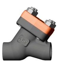
Piston check Y-type welded bonnet
ASME B16.25 - Refer to drawing for dimensions
CHECK VALVES - SCREWED & WELD END
80NB~150NB (2-1/2” ~ 6”) refer to drawing
80NB~150NB (2-1/2” ~ 6”) refer to drawing
DIMENSIONS Y-PISTON
80NB~150NB (2-1/2” ~ 6”) refer to drawing
Dimensions are indicative and vary according to standard, port design and body material. Refer to as-built drawing.
CHECK
- SCREWED & WELD END
Port (in)
65NB~150NB (2-1/2” ~ 6”) refer to drawing
65NB~150NB (2-1/2” ~ 6”) refer to drawing
DIMENSIONS Y-PISTON
65NB~150NB (2-1/2” ~ 6”) refer to drawing
Dimensions are indicative and vary according to standard, port design and body material. Refer to as-built drawing.
CHECK VALVES - SCREWED & WELD END
DIMENSIONS PISTON CHECK / BALL CHECK
65NB~150NB (2-1/2” ~ 6”) refer to drawing. 2690 Class refer to drawing.
DIMENSIONS Y-PISTON CHECK Dimensions
65NB~150NB (2-1/2” ~ 6”) refer to drawing. 2690 Class refer to drawing.
ASME B16.34 DESIGN
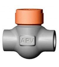
Seal Welded Bonnet (SWB)
ASME B16.34 DESIGN
100NB~300NB (4”~12”) refer to drawing. 2690 Class refer to drawing.
ASME B16.34 DESIGN
100NB~300NB (4”~12”) refer to drawing. 2690 Class refer to drawing.
100NB~300NB (4”~12”) refer to drawing. 2690 Class refer to drawing. 100NB~300NB (4”~12”) refer to drawing. 2690 Class refer to drawing.
ASME B16.34 DESIGN
MATERIAL SPECIFICATIONS GATE,
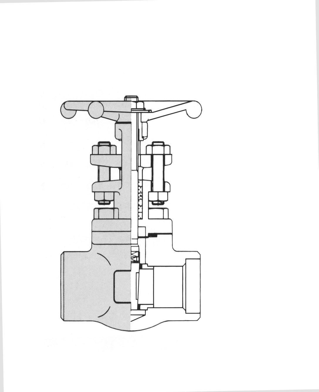
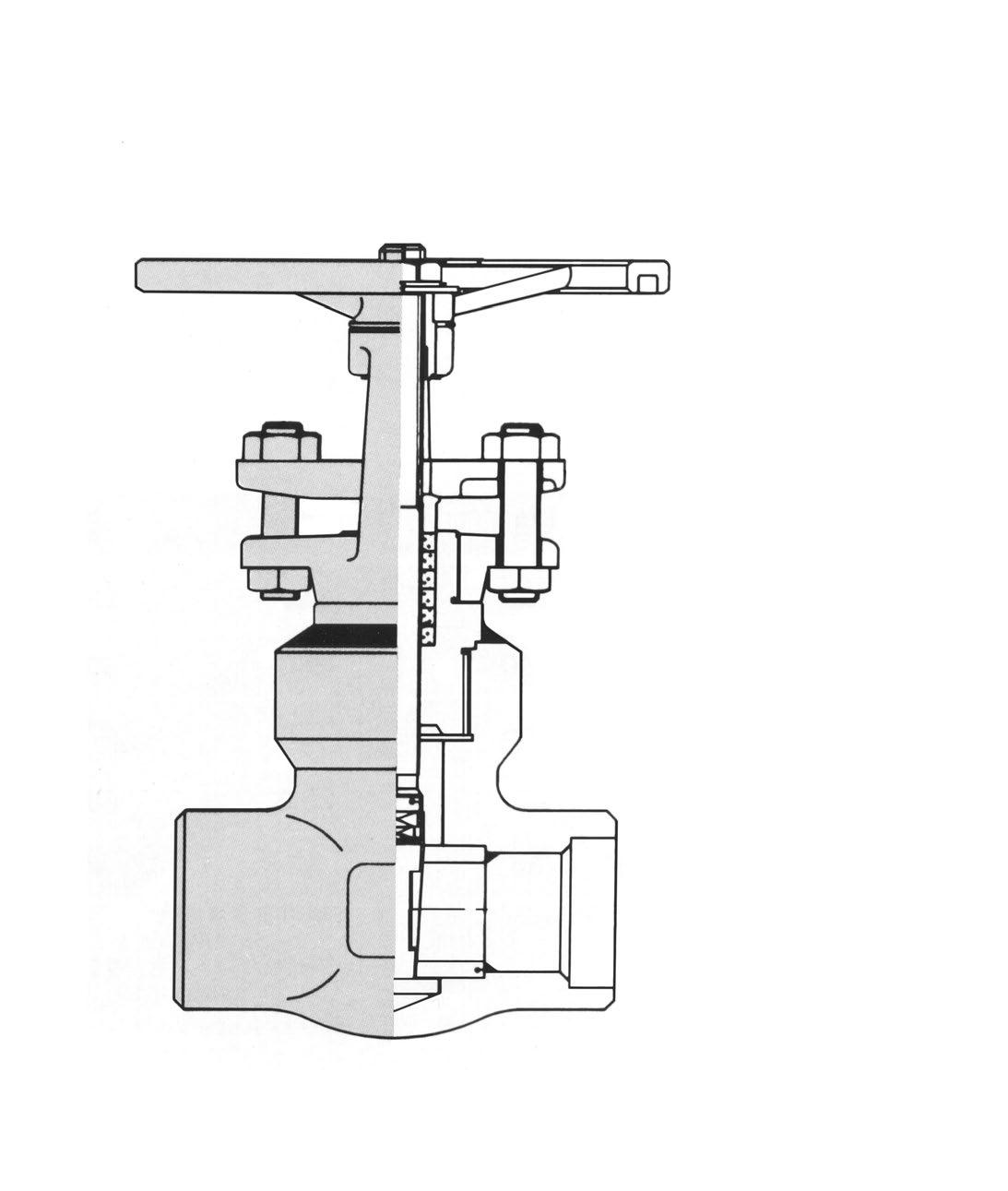
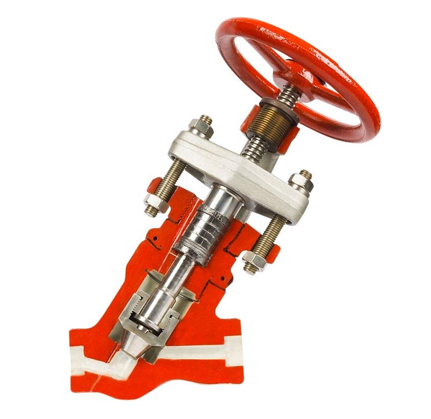
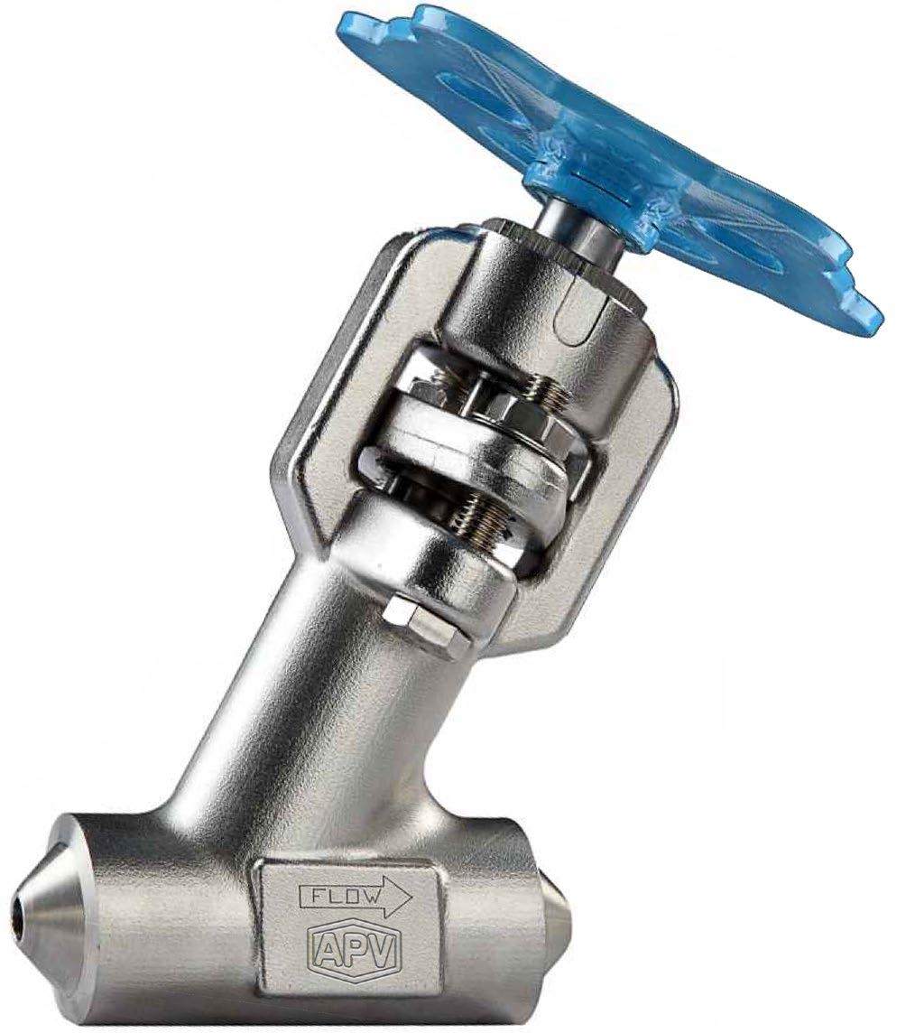
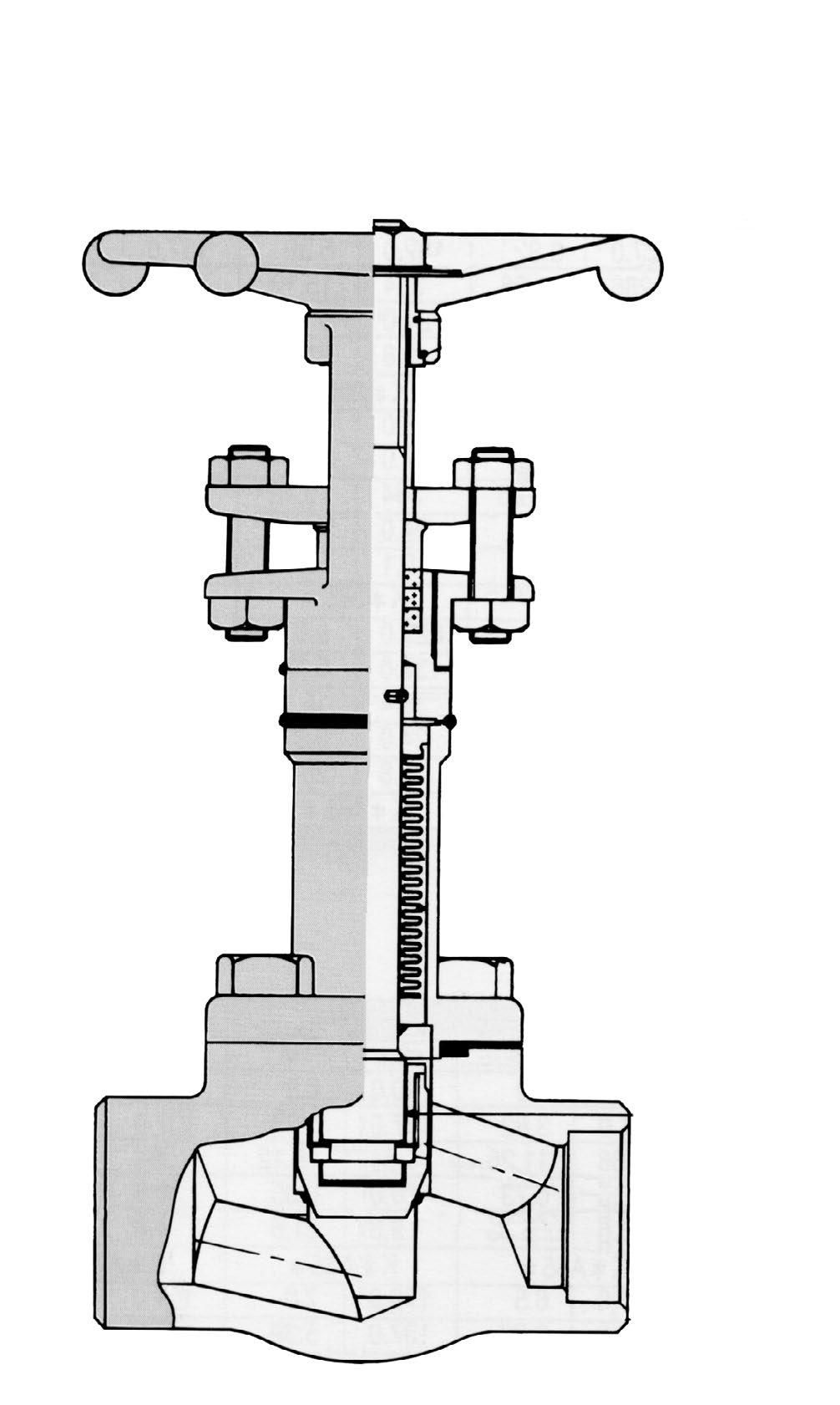
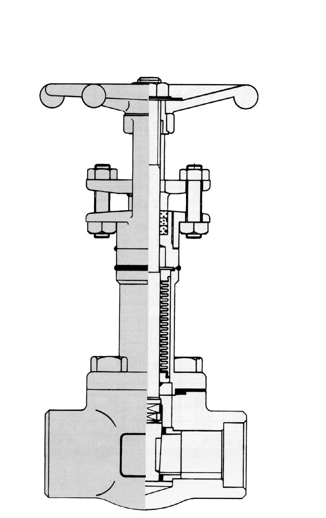
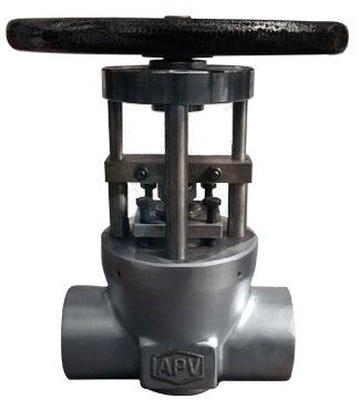
BONNETLESS GLOBE VALVES
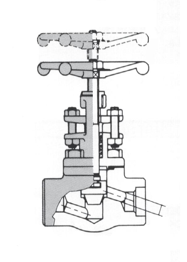
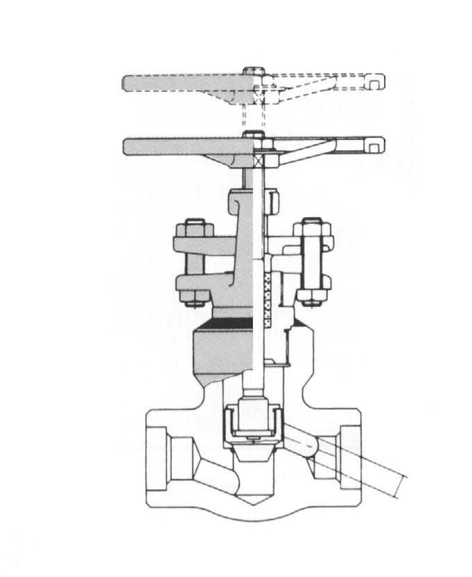
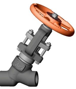
One-piece, forged, bonnetless globe valves have been proven in critical service applications around the world. This includes high pressure drop, steam blow down, steam injection etc.
These fast acting isolation valves are rated up to 2690 Class and can be utilised in gas and super heated steam at up to 1100°F (593°C).
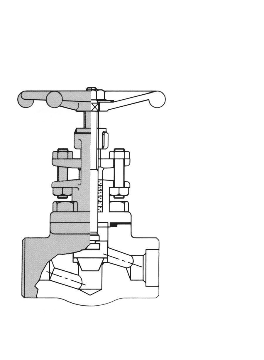
DESIGN FEATURES
One piece forged body
Eliminates pressure retaining threads or bolts. No welds to cut for servicing. Eliminates deposits.
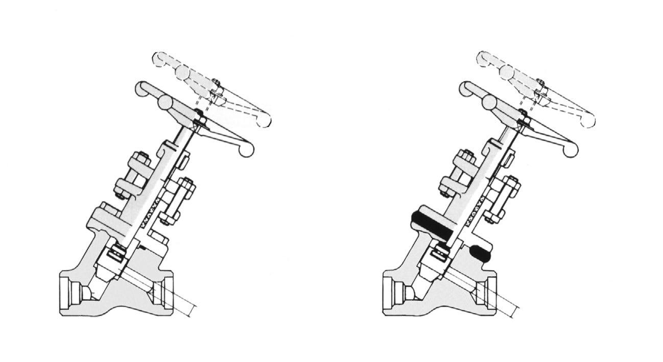
Y Pattern forged body
Excellent flow characteristics. Allows streamlined flow. Eliminates corrosion and deposits. 60° incline pressure drop.
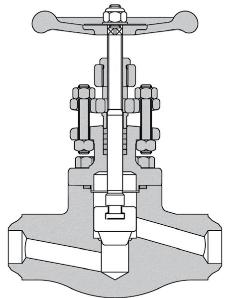
Heavy integral seating
Integral Stellite #6 seat & disc for long life. Tight shutoff.
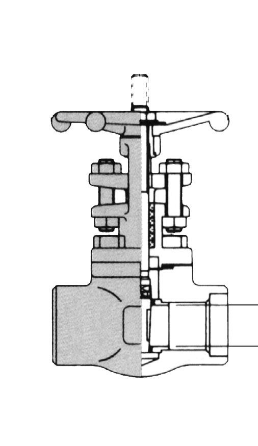
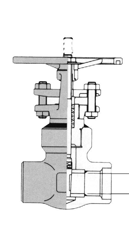
Long valve life.
Good flow characteristics. Ease of re-facing.
Positive seating function as standard. Seat is guided at bottom and top.
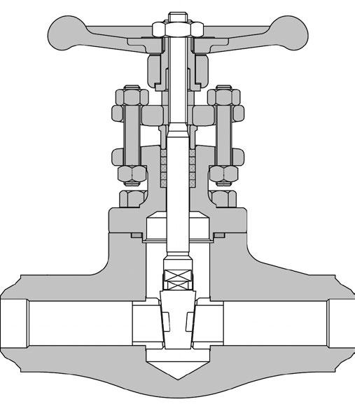
Non-rotating splined stem
Non-rotating solid cone eliminates galling and eliminates scoring or bending of the stem. No torsion applied to gland packing.
Easy on site maintenance and low maintenance cost. Low operational torque.
Can not be detached from the stem. Close roundness and straightness tolerances. Burnished for superior finish.
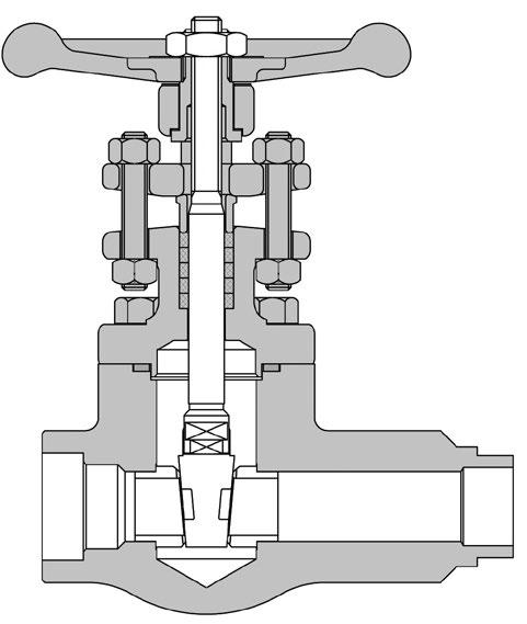
Combination gland ring packing
Graphoil as standard maximum temperature. 650 degree °C. Long operating life.
Heavy two-piece gland bushings
Will withstand high stresses caused by liveloading. Bolt torques control total spring load. Two sets of GLAND BUSHINGS maintain a minimum permanent stress of 4000 psi on the graphite packing keeping it tight for long periods of time without maintenance.
Double packing and leak-off
A lantern ring and leak-off pipe option allows detection or draining of leakage, if any, from the lower packing set.
Short and narrow packing chamber
Sealing effectiveness improves as overall packing length shortens. Chamber wall is burnished to a superior finish.
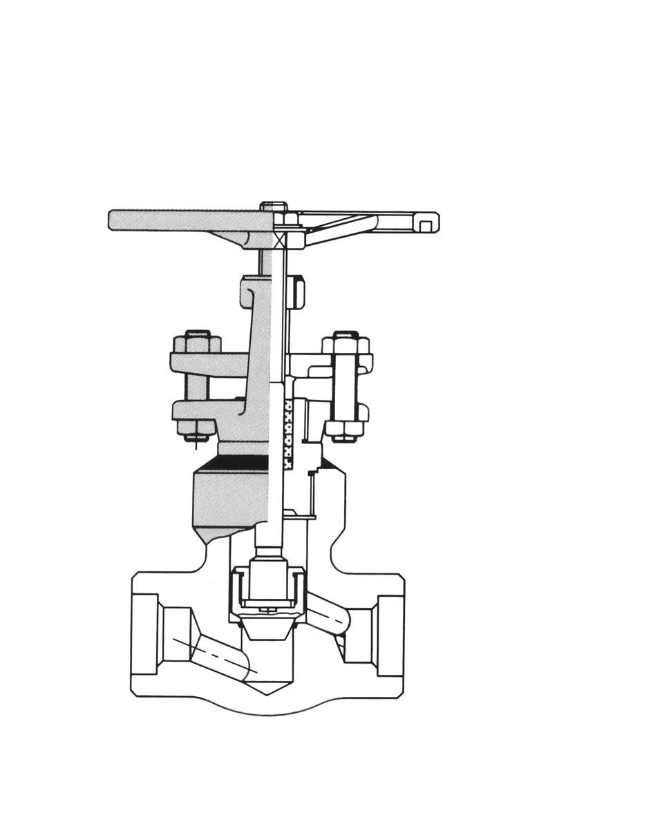
Handle wheel
Impact Hand-wheel is not necessary thanks to the two roller bearings.
Unique, fully-enclosed stem nutdrive
Well lubricated stem nut rotates on two thrust bearings. 10,000 test cycles show no visible damage to parts.
Dust cover and sleeve protect stem threads from dirt, dust and sand.
OVERVIEW
Size Range 8NB~50NB (1/4”~ 2”)
Rating 150 to 2500 Class
Design
End Connections
API 602, ISO 15761, ASME B16.34
Socket Weld - ASME B16.11
Thread - ASME B1.20.1 or ISO7/1
Butt Weld - ASME B16.25
Flange - ASME B16.5
Test and Inspection API 598
• Inconel or 321SS Bellows
- For longer life
- Maximum corrosion resistance
• Flanged, screwed or welded end connections
• Welded or bolted bonnet design
• Zero stem leakage
- Eliminates media loss
- Satisfies environmental regulations
• Zero maintenance
- Lower operating costs/no downtime
• Three stem seals for safety
- Metallic bellows
- Graphite packing
- Backseat in open position
• Reduce monitoring costs
• Hardfaced seating surface
- Stellite 6 for long life
• Additional alloy and trims available
• For applications where leakage into or out of the valve is unacceptable
- Heat transfer oil
- Toxic fluids
- Steam
- Regulated media
OVERVIEW
Size Range 8NB~50NB (1/4”~ 2”)
Rating 150 to 2500 Class
Design
End Connections
API 602, ISO 15761, ASME B16.34
Socket Weld - ASME B16.11
Thread - ASME B1.20.1 or ISO7/1
Butt Weld - ASME B16.25
Flange - ASME B16.5
Test and Inspection API 598
MATERIALS
* Stem Smoothness ≤ Ra 0.80 µm
** Stuffing Box Smoothness ≤ Ra 3.2 µm Refer to available range of materials on page 5. Refer to actual drawing for materials.
DESIGN FEATURES
• Inconel or 321SS Bellows
- For longer life
- Maximum corrosion resistance
• Flanged, screwed or welded end connections
• Welded or bolted bonnet design
• Zero stem leakage
- Eliminates media loss
- Satisfies environmental regulations
• Zero maintenance
- Lower operating costs/no downtime
• Three stem seals for safety
- Metallic bellows
- Graphite packing
- Backseat in open position
• Reduce monitoring costs
• Hardfaced seating surface
- Stellite 6 for long life
• Additional alloy and trims available
• For applications where leakage into or out of the valve is unacceptable
- Heat transfer oil
- Toxic fluids
- Steam - Regulated media
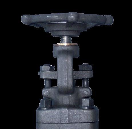
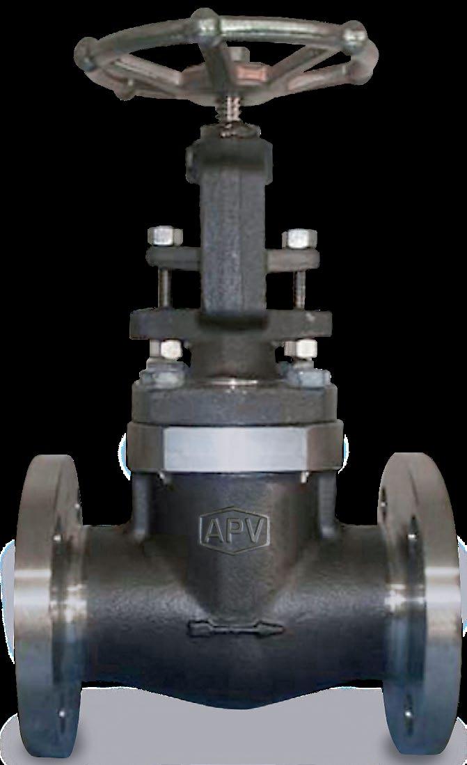
DESIGN FEATURES
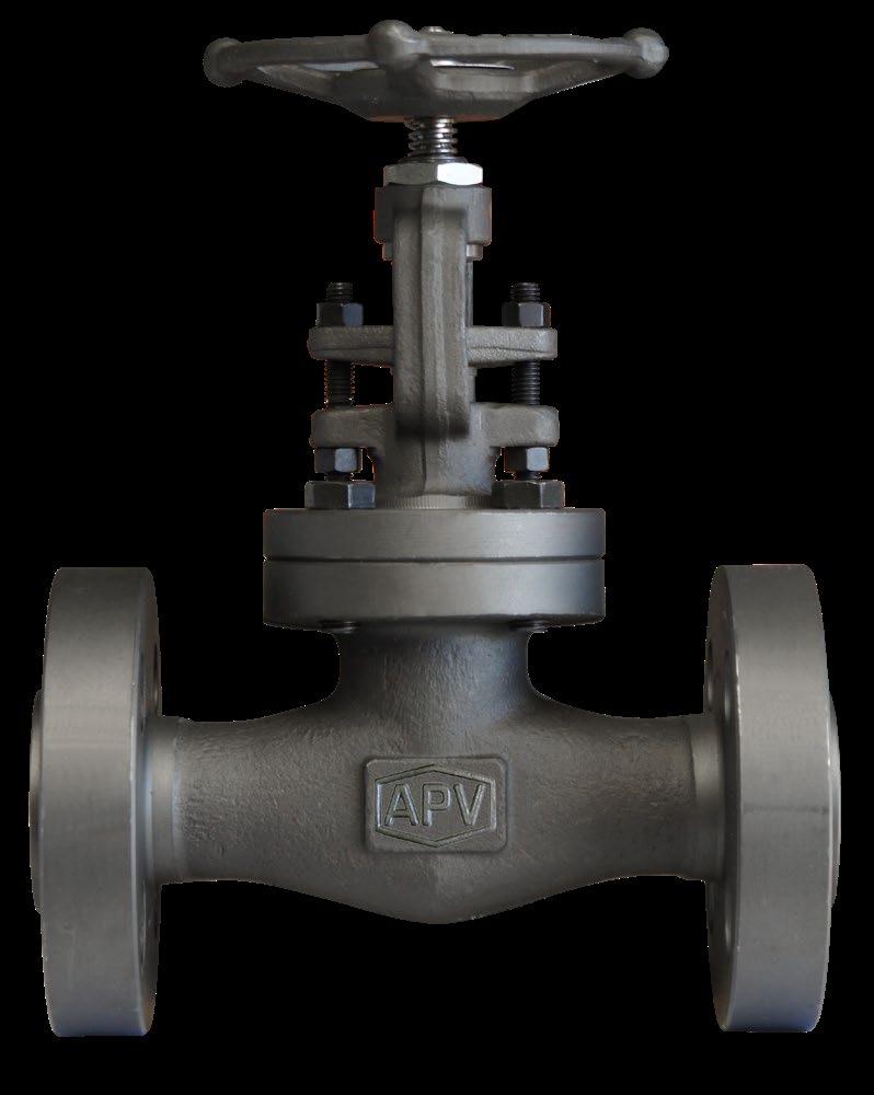
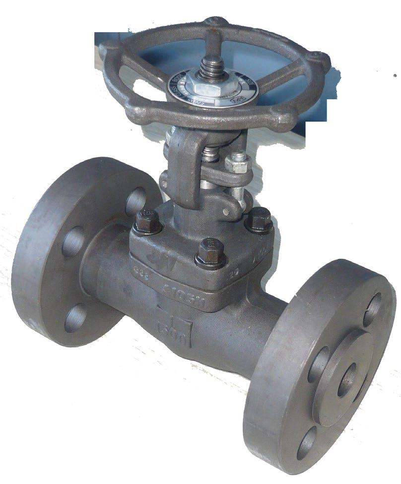
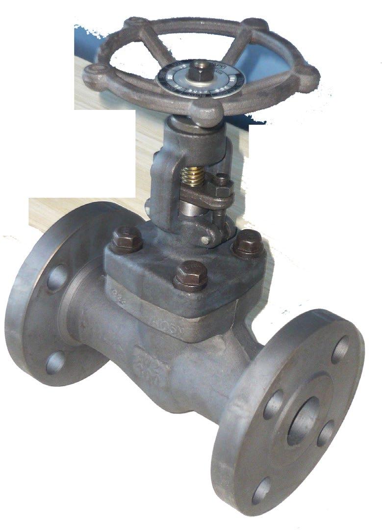
Integral Flanged Outside
Bolted bonnet & welded bonnet
Regular bore & full bore
Flanging to ANSI B16.5.
Other flanges available.
Alternative trim materials available.
* Stem Smoothness ≤ Ra 0.80 µm per API 602
** Stuffing Box Finish ≤ Ra 3.2 µm per API 602
Refer to available range of materials on page 5.
Refer to actual drawing for materials.


*Regular bore shown, full port refer to drawing.
CV FACTORS
Dimensions are indicative and vary according to standard, port
Refer to as-built
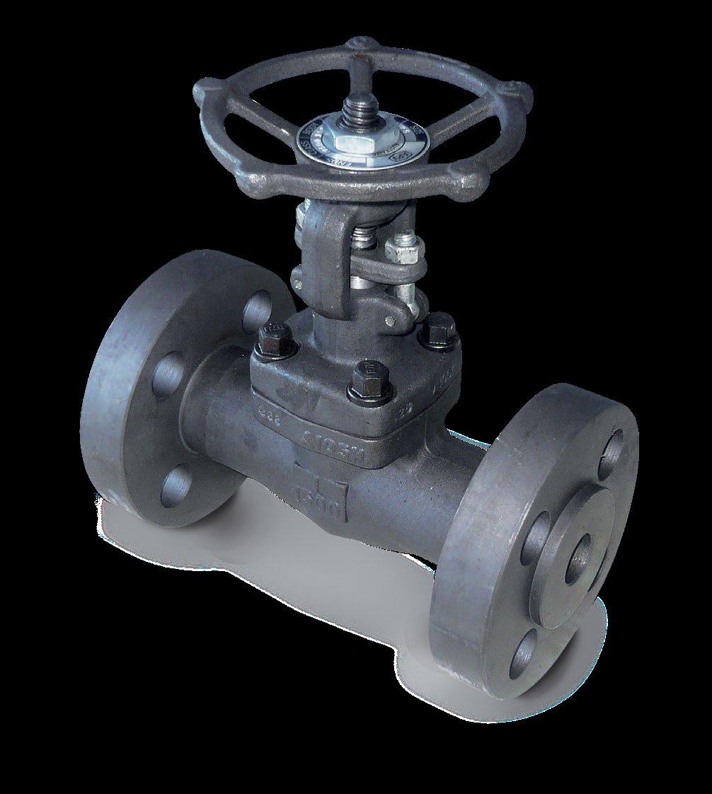
DESIGN FEATURES
Integral flanged.
Outside screw
Bolted bonnet & welded bonnet
Regular bore & full bore
Flanging to ANSI B16.5
Other flanges available.
Alternative trim materials available.
Inspection & Test API 598 * Stem Smoothness ≤ Ra 0.80 µm per API 602 ** Stuffing Box Finish ≤ Ra 3.2 µm per API 602 Refer to available range of materials on page 5. Refer to actual drawing for materials.
*Regular bore shown, full port refer to drawing.
CV FACTORS
Dimensions are indicative and vary according to standard, port design and body material. Refer to as-built drawing.
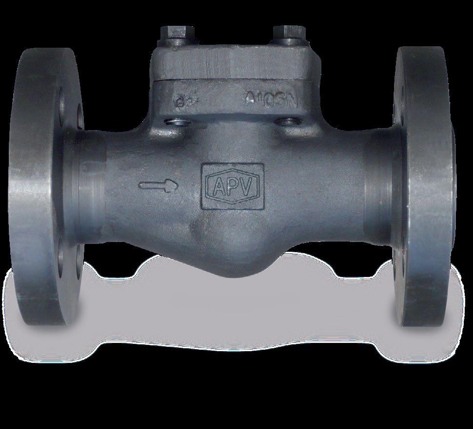
Bolted, welded and pressure seal bonnet. Integral flanged. Regular port and full port. Flanged to ANSI B16.5. Other flanging available. Alternative trim materials available. Spring can be fitted for vertical service to ball and piston type.
Refer to available range of materials on page 5. Refer to actual drawing for materials.

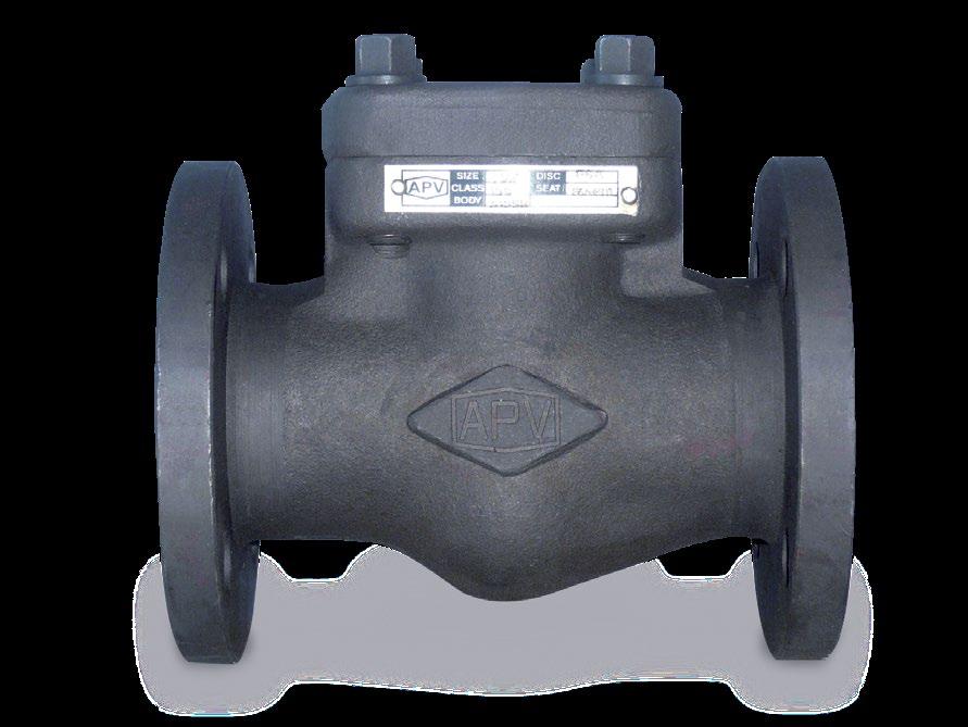
CHECK VALVES - FLANGED
* Port diameter shown is for piston and ball check regular port. For swing and for full bore piston and ball check refer to drawing.
CV FACTORS - LIFT CHECK*
* Reduced Port
CV FACTORS - SWING CHECK*
* Reduced Port
CV FACTORS - Y-PISTON CHECK*
* Full Port
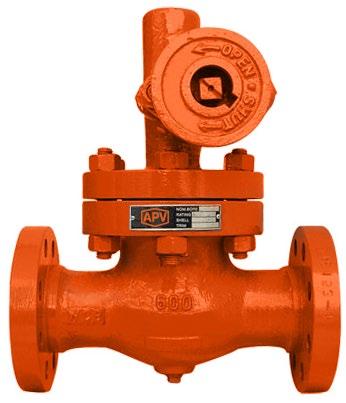
For installation in applications such as industrial, mining and mechanical services. Suitable for super-heated steam, H.T.H.W steam condensate and water.
This design consists of two discs, kept in contact with parallel body seats, using the line pressure and sprung seating action to effect tight closure.
Temperature changes in the line are accommodated by the expanding disc and do not affect the action of the valve. When being opened or closed, the discs slide across the seat faces, dislodging any foreign matter.
The valve operating stem is outside screw rising through the handwheel.
These valves are suitable for full bore steam use, where a low pressure drop across the valve is required. Also suitable for water, oil, gas, etc.
For superheated steam etc. consult chart. F11, F22, F5 chrome-moly available body for high temperature applications.
* Add XU modifier to end of model suffix if stellite seat, if stellite seat & disc add U modifier to end.
Contact us for detailed drawing.
* Stem Smoothness ≤ Ra 0.80 µm per API 602
** Stuffing Box Finish ≤ Ra 3.2 µm per API 602
Basic Design API 600, ANSI B16.34, BS 5157
Face to Face Dimension ANSI B16.10
End to End Dimension ANSI B16.10
Flanged Ends ANSI 16.5
B.W. Ends ANSI B16.25
S.W. Ends ANSI B16.11
Drilling to ANSI or BS/AS 2129 Table D to H or AS 4087 / AS 4331 / ISO 7005-1 PN 10 to 250
Pressure/Temperature ratings to ANSI B16.5
O.S. & Y. Rising Stem Full Port, Expanded Parallel Slide Gate Valve, Double Disc, Pressure Seal or Bolted Bonnet, Welded-in or Threaded Seat Rings. Mechanically loaded seating for low and high pressure sealing.
Parallel slide dual loaded discs ensure superior shut off and allow by-pass/bleed fitment (double block and bleed requires soft seat inserts).
Pressure/temperature charts available on request. Available in A105N, F22, F11, F5, 316, 304 etc.
For installation in applications such as industrial, mining and mechanical services. Suitable for super-heated steam, H.T.H.W steam condensate and water. This design consists of two discs, kept in contact with parallel body seats, using the line pressure and sprung seating action to effect tight closure.
Temperature changes in the line are accommodated by the expanding disc and do not affect the action of the valve. When being opened or closed, the discs slide across the seat faces, dislodging any foreign matter. The valve operating stem is outside screw rising through the handwheel. These valves are suitable for full bore steam use, where a low pressure drop across the valve is required. Also suitable for water, oil, gas, etc.
PRESSURE/TEMPERATURE A105N BODY
For superheated steam etc. consult chart. F11, F22, F5 chrome-moly available body for high temperature applications.
MATERIAL CODES
Contact us for detailed drawing.
* Stem Smoothness ≤ Ra 0.80 µm per API 602
** Stuffing Box Finish ≤ Ra 3.2 µm per API 602
Basic Design API 600, ANSI B16.34, BS 5157
Face to Face Dimension ANSI B16.10
End to End Dimension ANSI B16.10
Flanged Ends ANSI 16.5
B.W. Ends ANSI B16.25
S.W. Ends ANSI B16.11
Drilling to ANSI or BS/AS 2129 Table D to H or AS 4087 / AS 4331 / ISO 7005-1 PN 10 to 250
Pressure/Temperature ratings to ANSI B16.5
O.S. & Y. Rising Stem Full Port, Expanded Parallel
Slide Gate Valve, Double Disc, Pressure Seal or Bolted Bonnet, Welded-in or Threaded Seat
Rings. Mechanically loaded seating for low and high pressure sealing.
Parallel slide dual loaded discs ensure superior shut off and allow by-pass/bleed fitment (double block and bleed requires soft seat inserts).
Pressure/temperature charts available on request. Available in A105N, F22, F11, F5, 316, 304 etc.
(Pillar & Post style bonnet also available.)
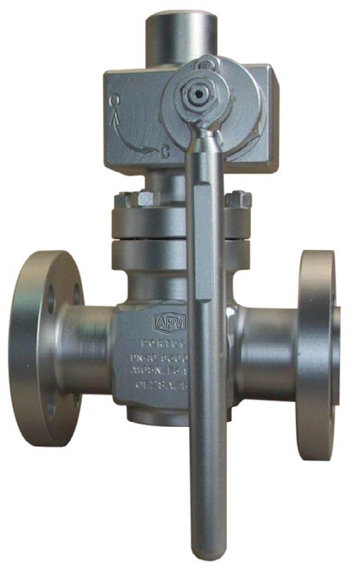
Key Operated Version (Integral Flanges)
PRESSURE/TEMPERATURE A105N BODY
Quick acting - Uniflo style lever or key operated continuous boiler blow down valves (blow off) for installation in applications such as industrial, mining and mechanical services. Suitable for super-heated steam, H.T.H.W steam
condensate and water.
This design consists of two discs, kept in contact with parallel body seats, using the line pressure and sprung seating action to effect tight closure. Temperature changes in the line are accommodated by the expanding disc and do not affect the action of the valve. When being opened or closed, the discs slide across the seat faces, dislodging any foreign matter. The valve operating stem is outside screw rising through the handwheel. These valves are suitable for full bore steam use, where a low pressure drop across the valve is required. Also suitable for water, oil, gas, etc. Also available in Globe style, quick acting.
Basic Design ANSI B16.34, BS 5157
Face to Face Dimension ANSI B16.10
End to End Dimension ANSI B16.10
Flanged Ends ANSI 16.5
B.W. Ends ANSI B16.25
S.W. Ends ANSI B16.11
Drilling to ANSI or BS/AS 2129 Table D to H or AS 4087 / AS 4331 / ISO 7005-1 PN 10 to 250
Pressure/Temperature ratings to ANSI B16.5
For superheated steam etc. consult chart. F11, F22, F5 chrome-moly available body for high temperature applications.
TRIM
Hastelloy B Hastelloy B Hastelloy B Hastelloy B
* Add XU modifier to end of model suffix if stellite seat, if stellite seat & disc add U modifier to end.
O.S. & Y. Rising Stem Full Port, Expanded Parallel Slide Gate Valve, Double Disc, Bolted Bonnet, Integral Seal Rings - Metal to Metal. Mechanically loaded seating for low and high pressure sealing.
Parallel slide dual loaded discs ensure superior shut off and allow by-pass/bleed fitment (double block and bleed requires soft seat inserts).
Pressure/temperature charts available on request. Available in A105N, F22, F11, F5, 316, 304 etc.
A105N
A182 F5/F5A
A182 F11 8 A182 F304/304L
Australian Pipeline Valve don’t consider in our design the following factors of risk:
1. Australian Pipeline Valve ‘Standard’ valves can be used in a temperature range between -29 to +490°C. (Note, pressure limitations apply above 38°C refer to Pressure/Temperature charts.) For service temperatures below -29°C valves construction materials shall be submitted to an impact test at the minimum service temperature. For temperatures above and below the standard range, special seals need to be specified by the client.
2. The onus is on the customer to specify all materials of construction and service conditions. Australian Pipeline Valve shall assume standard materials and conditions if not otherwise specified.
3. Australian Pipeline Valve ‘Standard’ valves are not equipped with devices suitable to avoid internal over-pressures caused by incorrect operations of process or by-fluids & liquids subjected to an increase of volume and/or pressure (these devices, such as the over-pressure hole in the gate or safety seats are available upon request).
4. Australian Pipeline Valve ‘Standard’ valves are not designed with special devices to withstand a sudden thermal jump (thermal shock).
5. In general Australian Pipeline Valve ‘Standard’ valves are not mechanically designed to bear overloads due to exceptional atmospheric or natural phenomenon’s (such as earthquakes).
6. In general Australian Pipeline Valve ‘Standard’ valves are not designed to bear loads on flanges, on pipe connections or pipe-line.
7. In general Australian Pipeline Valve ‘Standard’ valves can’t withstand ice inside their bodies (in this case the user has to consider the optional stem extension for insulating, avoiding the presence of residual product inside the valve).
8. Australian Pipeline Valve ‘Standard’ valves are not suitable for low temperature service below -29°C (-20°F) unless supplied (in a suitable body material) with cryogenic stem extension and other modifications, (available on request).
9. Australian Pipeline Valve ‘Standard’ valves are suitable for ‘industrial’ oxygen (not medical) service when supplied degreased and packed in polyethylene bags only.
10. The compatibility between the valves construction materials and medium is selected by the user. The user is ultimately responsible for verifying the compatibility between medium and materials.
11. Abrasive or dirty service applications need to be considered and stated at time of order.
Before installing the valve onto the pipe-line it is mandatory, for the user, to verify the compatibility of the valve with service conditions (medium, temperature and pressure). With reference to standard valves held in stock, the reseller and end user will have to assure themselves of the compatibility between the valve and the conditions required by the customer. Australian Pipeline Valve gate valves must be only used for on-off (fully open/fully closed) service.
Before using the valve in a potential explosive atmosphere it’s necessary for the customer to: -
• To verify the correct type of valve and operator is specified.
• To verify the compatibility between the valve and the zone in which the valve should be installed
• To foresee the pipe-line ground condition on which the valve should be installed
• To check that the temperature if the valve surface is not higher than the flammable point of the atmosphere in which the valve is installed (in this case specify an insulating cover device for the valve and an extension for the operator)
• To avoid mechanical knocks during the installation that may cause sparks.
Australian Pipeline Valve cannot be held responsible for damage caused by use of the product for any reason, especially if it is improper use or modified.
“Australian Pipeline Valve produces isolation, control and flow reversal protection products for severe and critical service media in utility, steam, pipelines, oil & gas and process industries. APV valves and pipeline products form the most competitive portfolio in the market.”