Please see the inside of the back cover for instructions of where to find your model and serial number.
To prevent personal injury or even death, be sure you read and understand all the instructions in this manual and other related OEM equipment manuals! This attachment, if not used and maintained properly, can be dangerous to users unfamiliar with its operation. Do not allow operating, maintaining, adjusting, or cleaning of this attachment until the user has read this manual and has developed a thorough understanding of the safety precautions and functions of the unit. This attachment is designed for the purpose specified. DO NOT modify or use this attachment for any application other than that for which it was designed. Attachments maintained or operated improperly or by untrained personnel can be dangerous, exposing the user and/or bystanders to possible serious injury or death.
Thank you for choosing Lackender. This attachment has been designed and manufactured to meet the needs of discerning users. We are committed to providing you with a heavy duty product that will provide years of satisfaction and safe operation.
This manual will provide instructions on how to safely operate and maintain this attachment. All users must read and understand this manual before operating this attachment. Upon reading this manual, all users should sign the “Safety Acknowledgment Form” at the end of this manual.
Please record your model and dealer information on the inside front cover. You will be asked to provide this information when ordering parts or requesting service. If you need more information on this product, contact your local dealer or visit www.ecsattachments.com.
ATTENTION: If your attachment has control valves, cylinders, gearboxes, or motors and they are opened or disassembled, the WARRANTY for that item WILL IMMEDIATELY BE VOIDED!
GEAR OIL STATEMENT: If applicable in your attachment, check gear oil before each use:
We recommend using 85-140 grade gear oil, for use with all our gear boxes, and bearing housings which is separate from the hydraulic fluid used to move your attachment or machine. (Exception: gear oil used in mulchers is Shell Omala S2 GX 150!)
HYDRAULIC FLUID STATEMENT: Check your machine’s hydraulic level and add hydraulic fluid if necessary before each use. Inspect for leaks, and repair if necessary. Always use your machine’s manufacturer recommended hydraulic fluid in your machine! Fluid must be clean and debris free. If damage occurs from debris in hydraulic fluid flowing from your machine to our attachment it will VOID the warranty on any cylinders, motors, couplers, manifolds &/or valves (relief, lock, selector, check and flow control) down line from that flow.
SECTION 2 Grapple Models
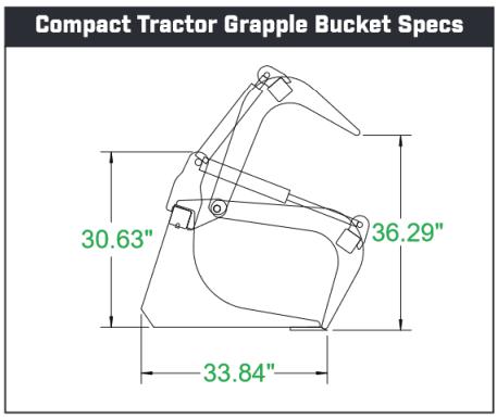
Compact Tractor Grapple Bucket
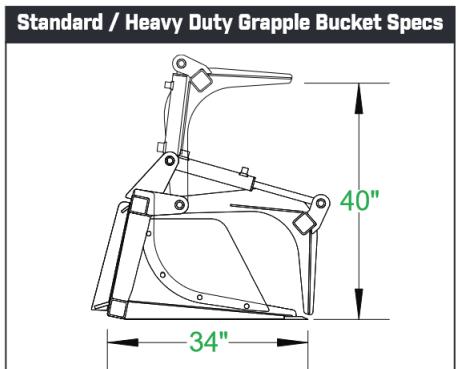
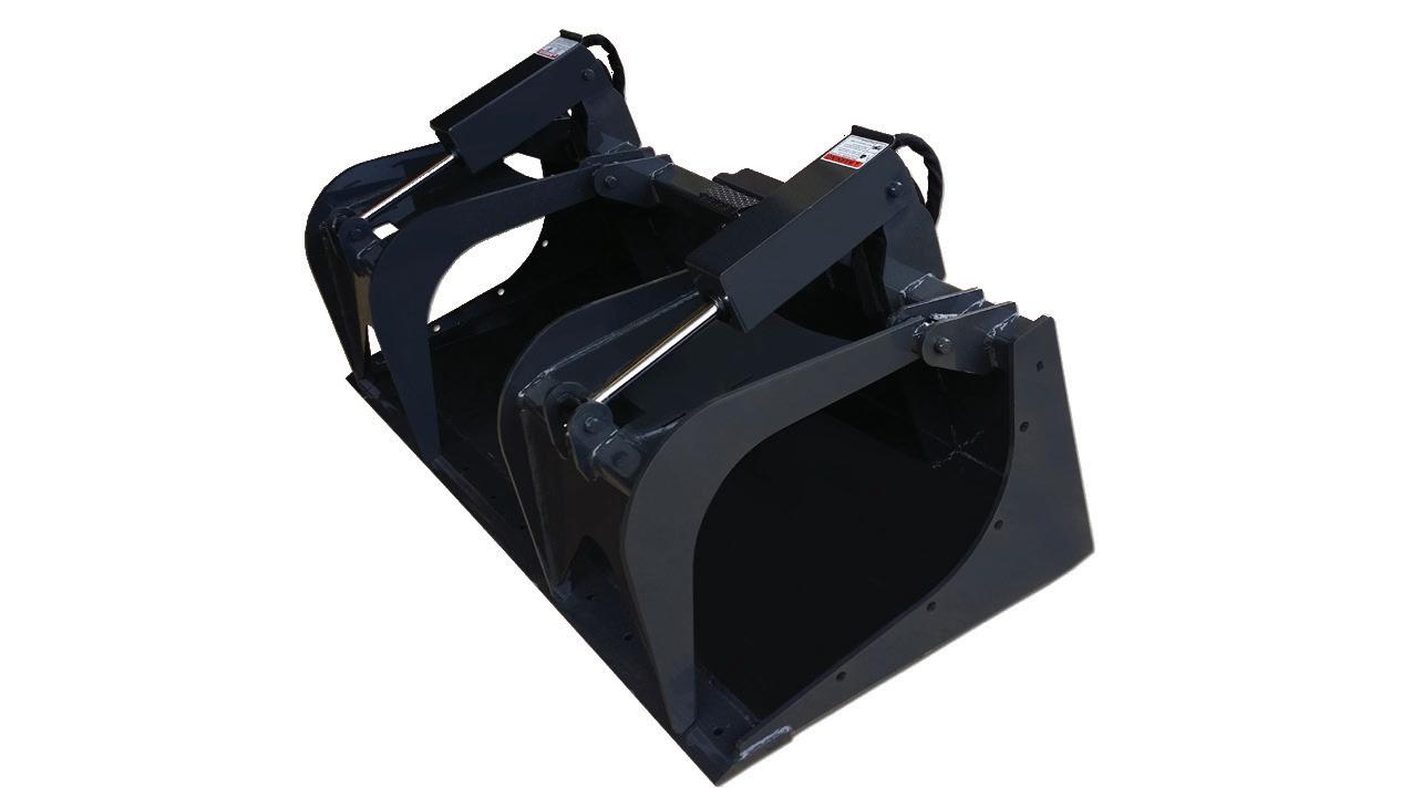
Standard & Heavy Duty
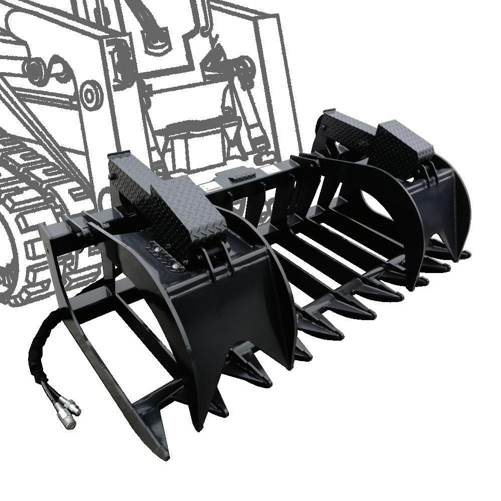
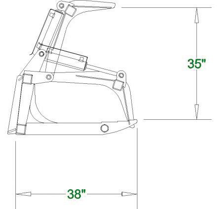
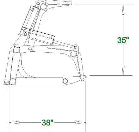
The Grapple Buckets are very versatile attachments. They are available in a wide range of sizes and easily pick up logs, rocks, left over building supplies, or any other type of debris. They can also be used to smooth dirt while clearing and grabbing.
All Grapple Buckets have cylinders, with all hydraulic lines routed inside the tubing to prevent tears. They are also built with top quality steel, oversized points & bushings, with grease fittings at every pivot point. Every unit exceeds the lifting capacity of the skid steer machine it is attached to.
Mini size offered as well.
• Grease fittings at every pivot point
• Optional: weld on teeth & bolt on cylinder
• rod cover kit.
• Optional: bolt on edge
• Heavy Duty: bolt on sides included.
• Compact rated for up to 35 HP
• Standard rated for up to 45 HP
• Heavy Duty rated for 45- 65 HP
•
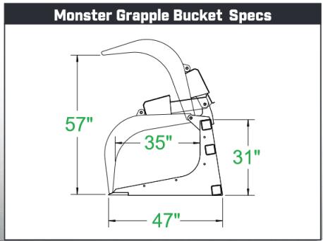
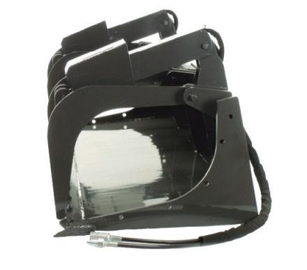
Monster Grapple Bucket
• Optional Bolt On Cutting Edge
• Used for telescoping loaders (telehandlers.)
• Reinforced with extra tubing and ribs.
• Rated for 100 HP
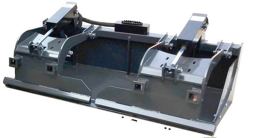
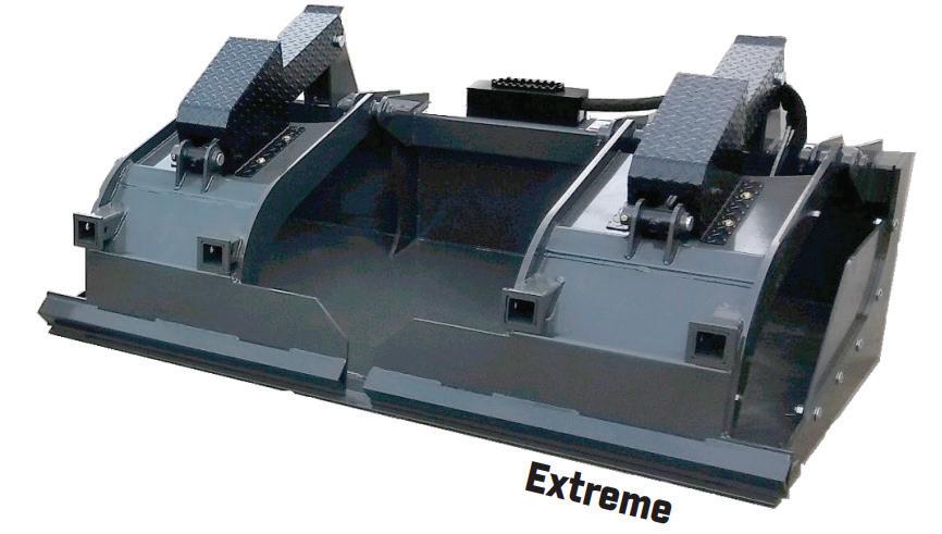
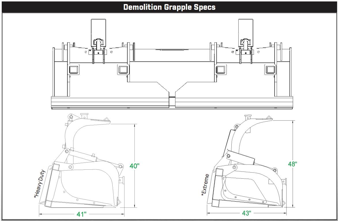
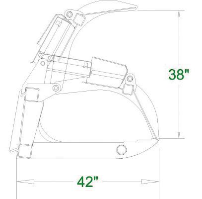
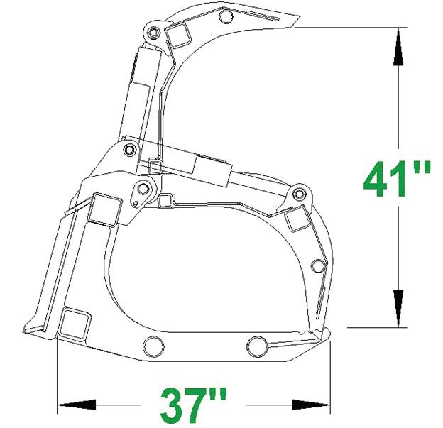
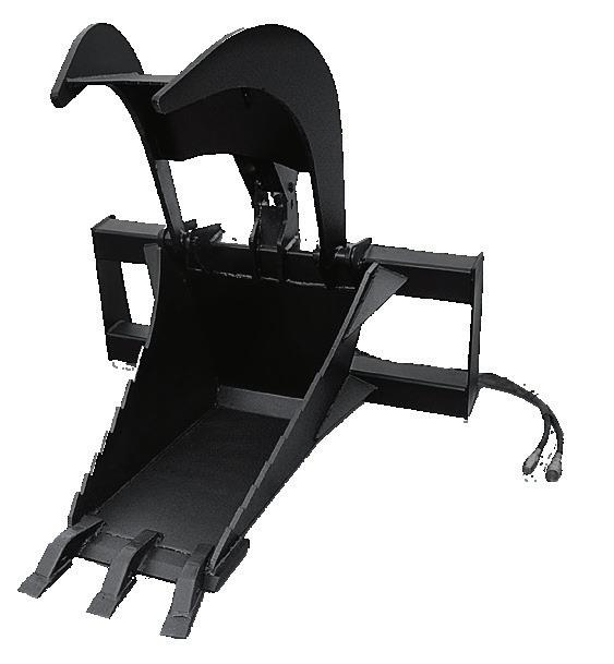
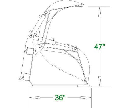
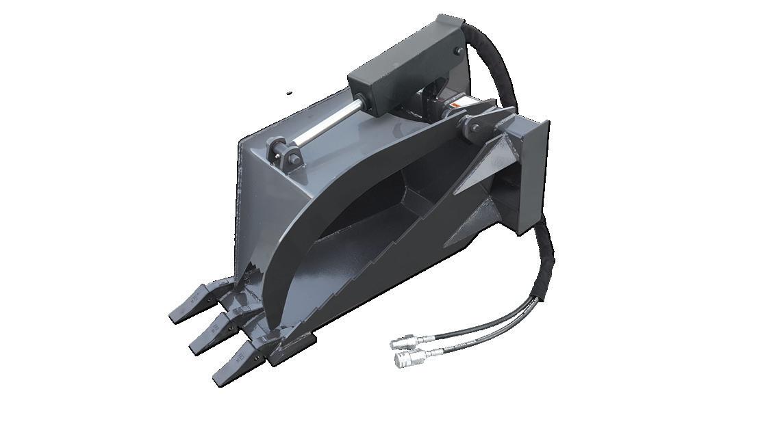
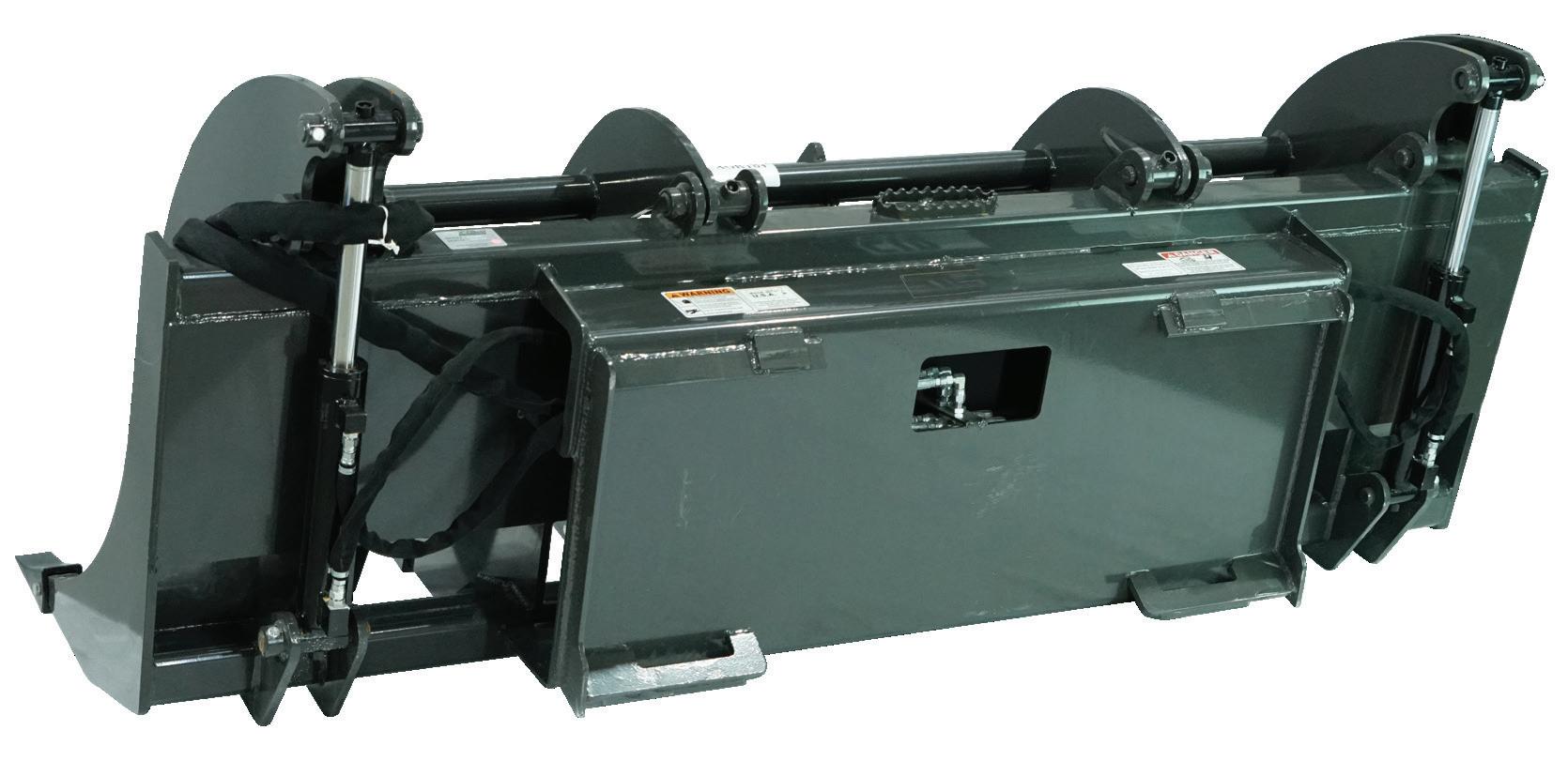
Demolition Grapple
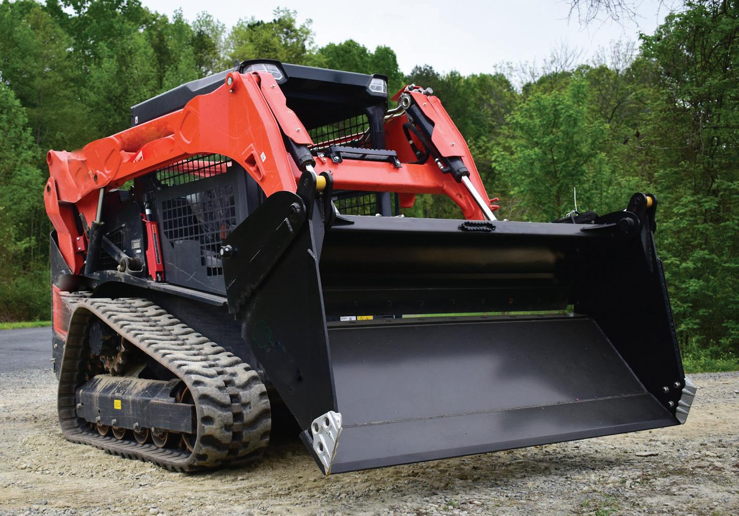
This Demolition Grapple combines multiple functions into one unique attachment. The Demolition Grapple replicates the functions of a general purpose bucket, 4-N-1 Bucket, Dozer Blade, Grapple, Clam Shell, Log Handler, and Demolition Bucket. It is also equipped with tool receivers, predrilled holes for bolt on edges, chain hooks with pins, and removable sides.
●Hydraulic lines routed inside tubing to prevent tears.
●Bolt on sides included.
●Heavy Duty: Optional bolt on rod cover kit.
●Heavy Duty rated for: 45-65 HP
●X-Treme rated for: 65+ HP
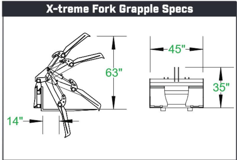
X-Treme Fork Grapple
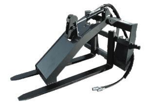
Fork Grapples are ideal for farm work, logging operations, and general contracting functions. The top tine is adjustable for small or large loads and the hydraulic cylinders gives plenty of clamping force. The fork tines are completely heat treated.
Available in 48”, 60” and 72” tines.
● Weight Rating: 8,000 lbs.
● Class 3
2.2 Fork GrappleS
2.2 Fork GrappleS
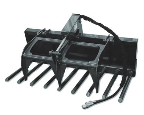
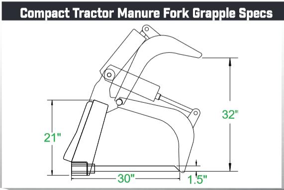
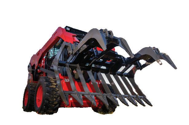
Compact Tractor Manure Fork Grapple
These forks are useful for manure and general pick up of materials when you only want to pick up the item and not the soil around it. The tines slide in through the front and are pinned from the rear.
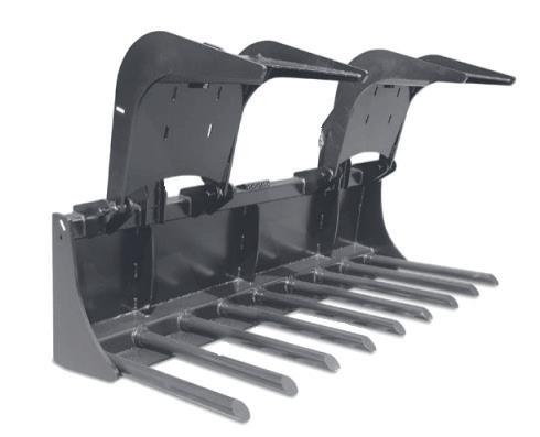
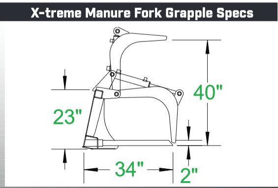
X-Treme Manure Fork Grapple
Whether moving bales of hay or cleaning up after storm damage, there are many uses for this attachment.
2.3 Mat GrappleS
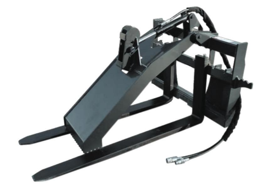
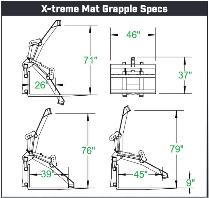
X-Treme Mat Grapple
Our X-Treme Mat Grapple is designed to pick up and move equipment mats. It can also be used to transport logs, poles, and just about anything else. We build this with a lifting capacity of 8,500 lbs.
● Durable heat treated forks.
● Teeth on grapple to grip the mats.
● 60” Forks Standard
●Rated for up to 35 HP.
●X-Treme Rated for 65+ HP
● Strong rolled steel tines on bottom.
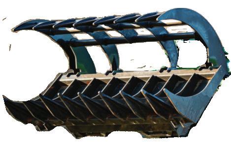
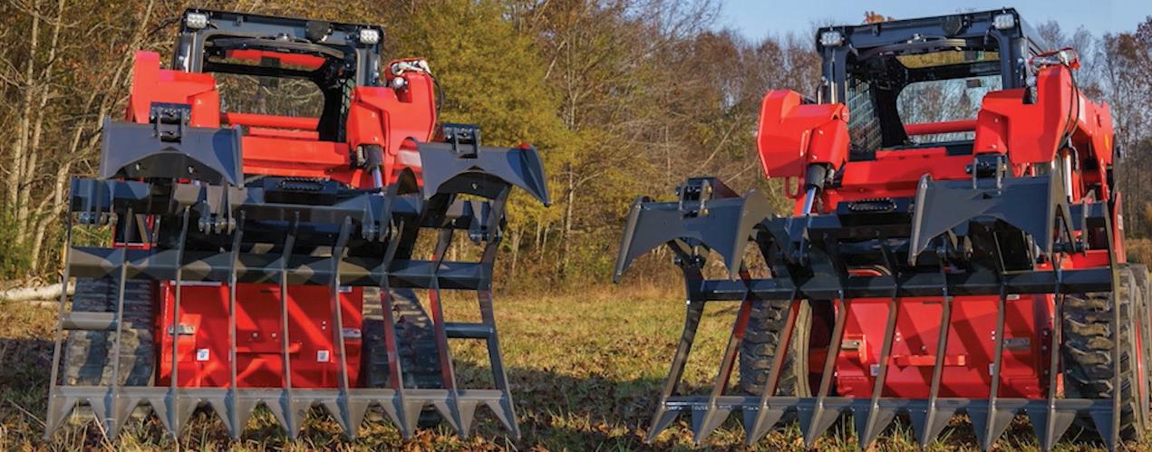
2.4 Grapple Rakes
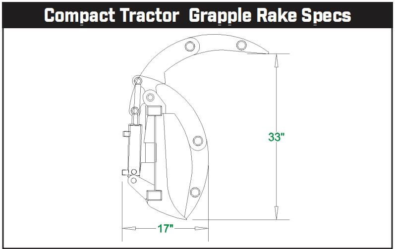
Compact Tractor Grapple Rake
Grapple Rakes are ideal for raking and loading debris. The shape of the grapple makes is easy to roll debris into tight places. These grapples use American made cylinders that are built to handle the toughest jobs.
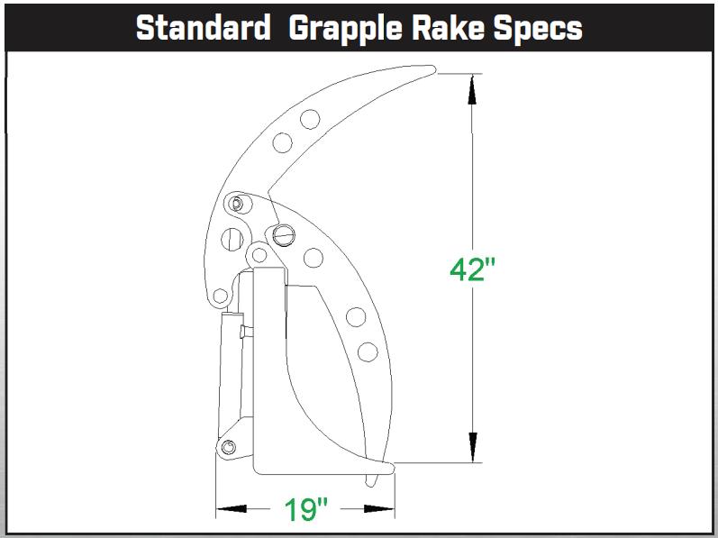
Standard Duty Grapple Rake
The Re-designed Standard Duty Grapple Rake is constructed from high quality steel and designed for more strength with a lower weight to maximize your grappling power.
●Standard Rated for up to 45 HP.
The Compact Tractor Grapple Rake is built heavy enough for rigorous use, but light enough for compact tractors. The Compact version is available with a single cylinder or double cylinder grapple.
●Compact Rated for up to 35 HP
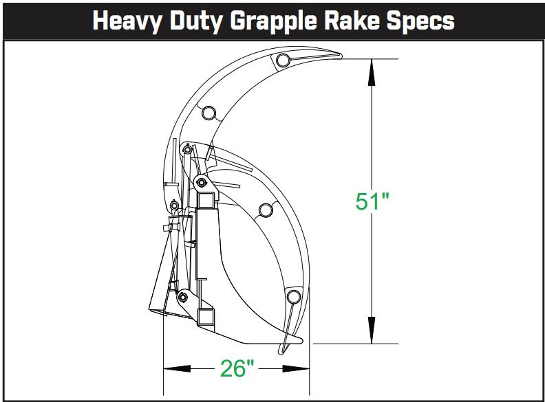
Heavy Duty Grapple Rake
The Heavy Duty Grapple Rake is ideal for those tougher jobs and comes in a single or double grapple.
●Heavy Duty Rated for 45-65 HP
2.4 Grapple Rakes
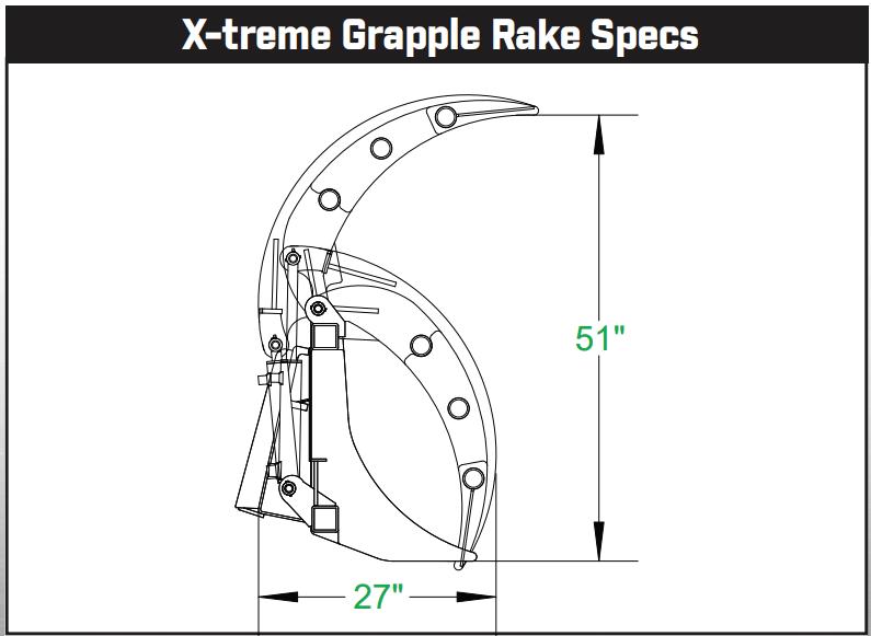
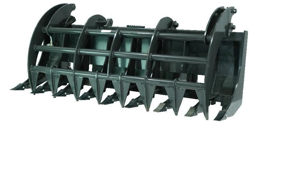
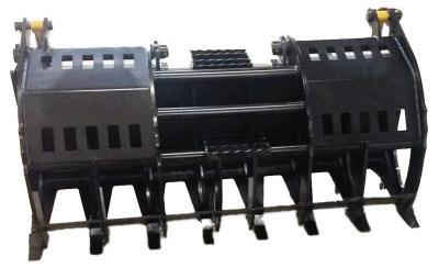
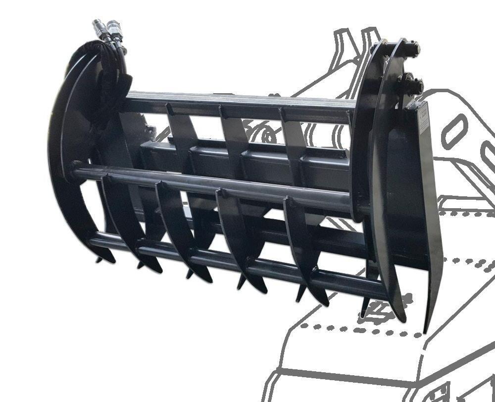
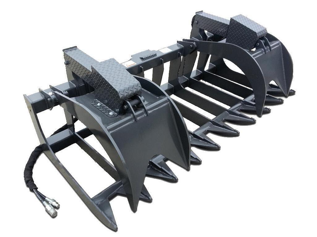
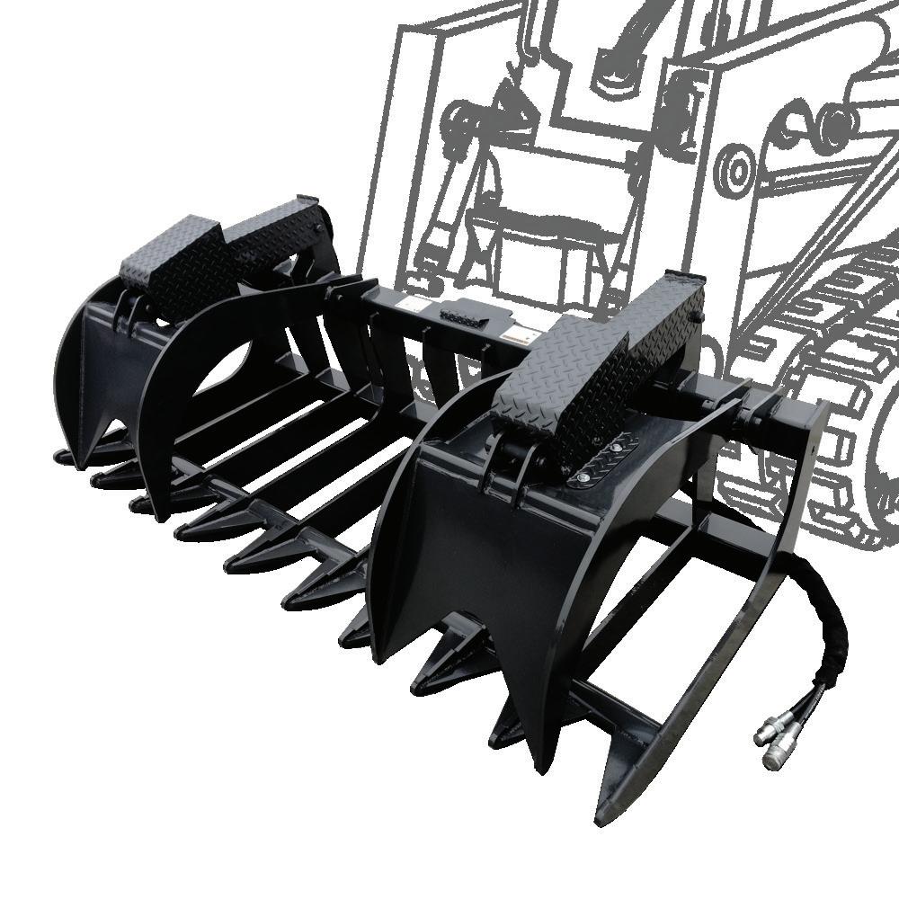
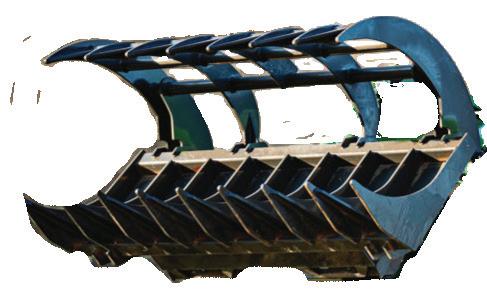
X-Treme Grapple Rake
The X-Treme Grapple Rake is built with top quality steel and is ideal for raking up debris. It can also be used to load the debris into a dump truck. The X-Treme Grapple Rake comes in a single or dual grapple option and has twin cylinders to handle the toughest job.
●X-Treme Rated for 65+ HP
Severe Grapple Rake
The Severe Grapple Rake is built with top quality steel and is ideal for the bigger machines. It works well for raking debris, brush, logs and more. The powerful clamping force will hold the material in the most severe conditions.
●Severe Rated for 80+ HP
Compact Mini Grapple Rake
The Compact Mini Grapple Rake is great for a small skid steer in small areas and makes it easy to roll debris into tight piles. This Mini Grapple Rake is made with top quality steel and has twin stroke cylinders to handle the toughest jobs.
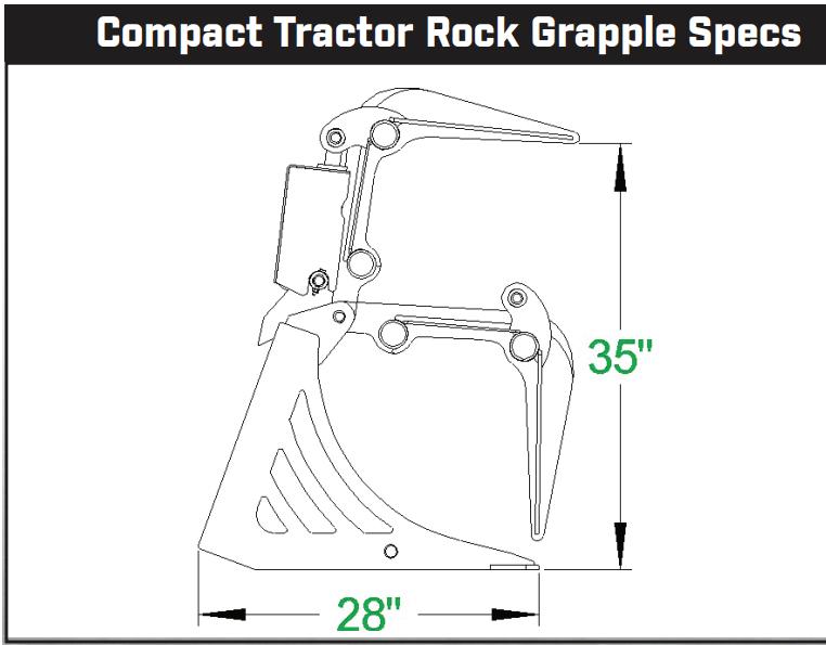
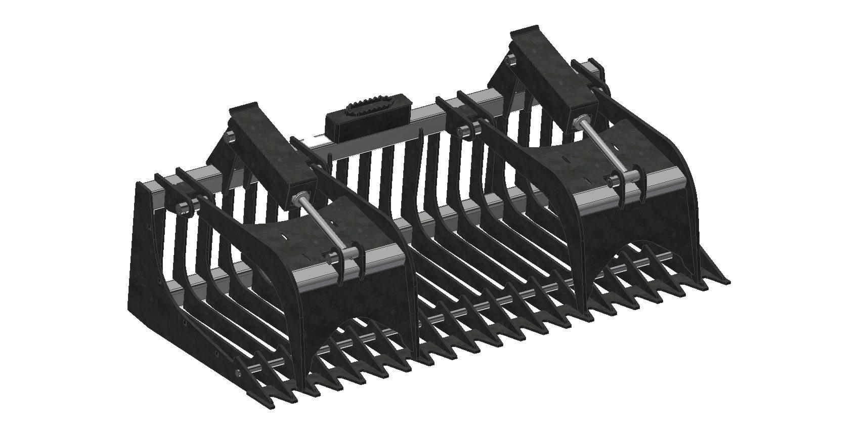
Compact Tractor Rock Grapples
The Rock Grapples were designed to fit your needs of sifting through dirt to remove rocks and debris.
The Compact Tractor Rock Grapple comes with a single grapple.
●Compact Tractor Rated for up to 35 HP
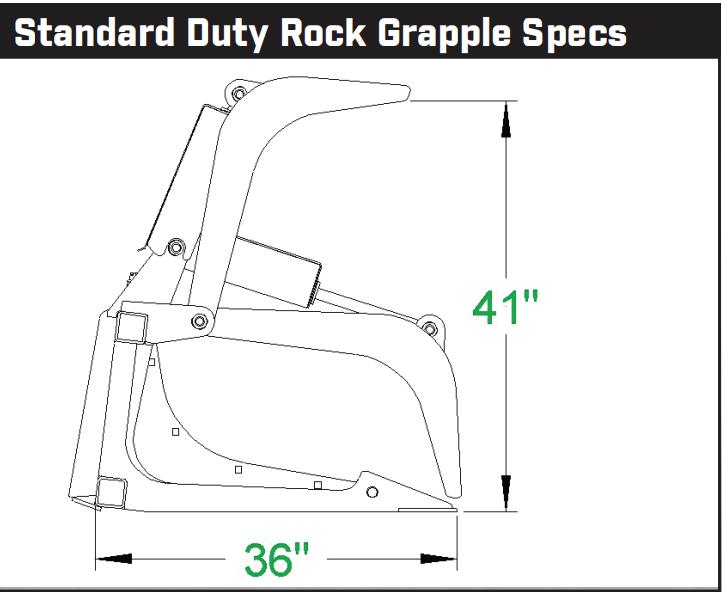
●Standard Duty Rated for up to 45 Standard Duty Rock Grapples
The Standard Duty Rock Grapple has dual cylinders.
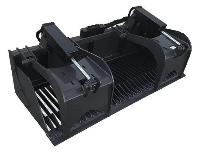
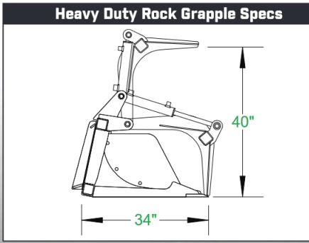
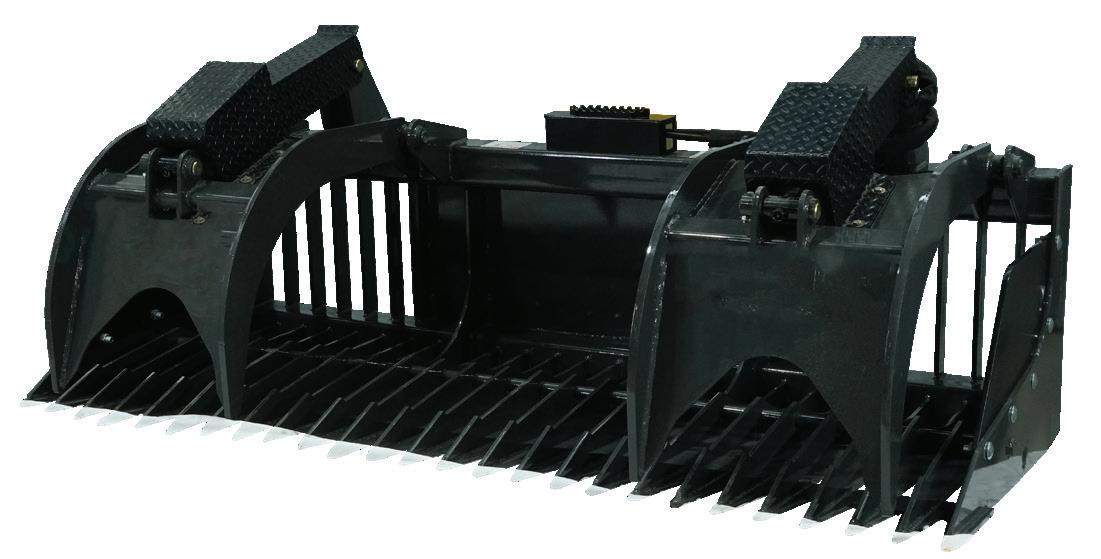
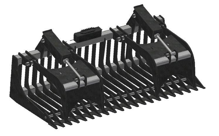
Heavy Duty Rock Grapples
The Heavy Duty Rock Grapple is built with tine spacing to capture even smaller rocks and is equipped with a cutting edge. Dual cylinders en able optimal function.
●Heavy Duty Rated for 45-65 HP
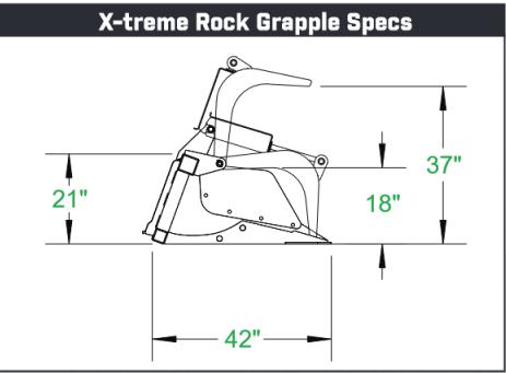
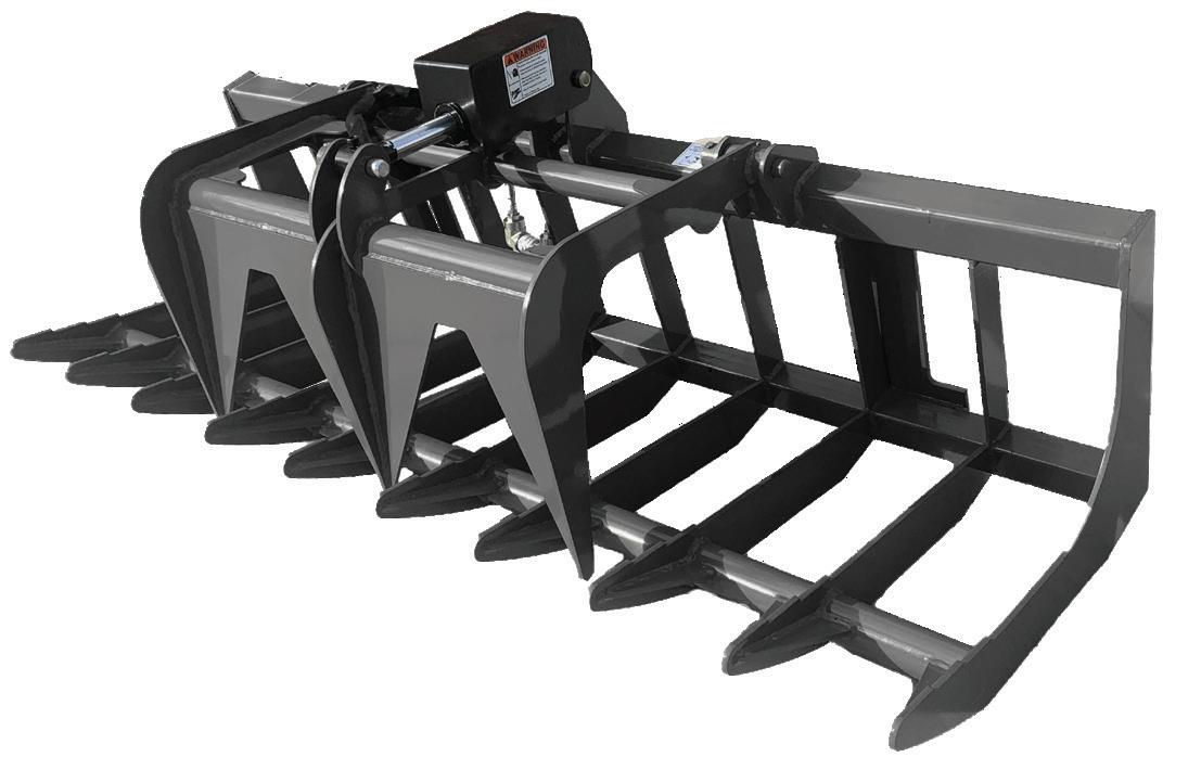
2.5 Rock GrapPLES
The X-Treme Rock Grapple was designed with top quality steel and fully welded front teeth to better enable smooth removal of rocks, logs, and brush.
Grapples
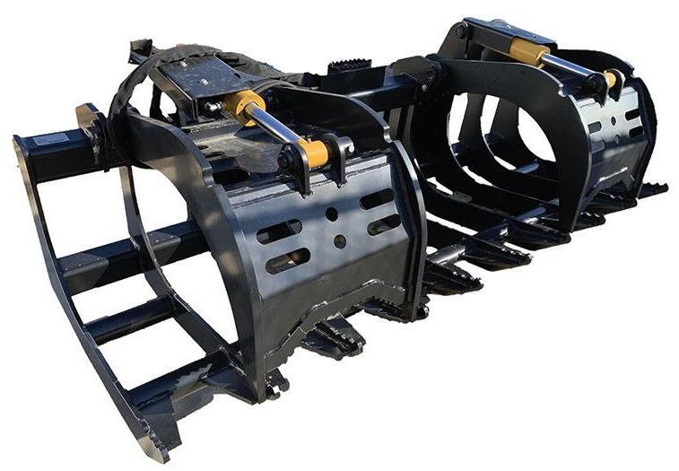
Root Grapples were designed due to necessity for the tree industry. Contractors also use Root Grapples to clear lots for home building sites. They are ideal for moving logs, brush, rocks, or about any type of debris and work great for storm clean up as well.
All of the Root Grapples listed are built with top quality steel and will exceed the lifting capacity
of the skid steer they are used on. They feature independently operated cylinders to adjust on uneven loads and have grease fittings at every pivot point to ensure smooth function.
Optional bolt on cylinder rod covers protect the hydraulic cylinder shaft which can eliminate damage from falling debris.
2.6 RoOT GrapPLES
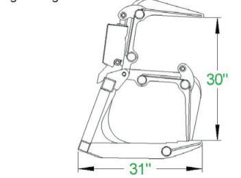
Compact Tractor Root Grapples
Compact Tractor Root Grapple
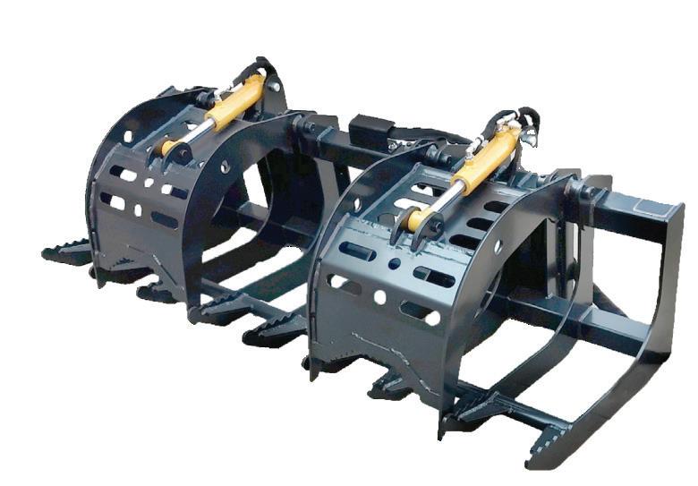
Ultra Root Grapple
The Ultra Root Grapple is a more robust version than the Compact version.
●Ultra Rated for 35-50 HP
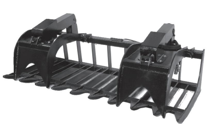
●Standard Rated for up to 45 HP
●Hydraulic lines routed inside tubing to prevent tears.
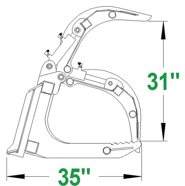
●Heavy Duty Rated for 45-65 HP
●Hydraulic lines routed inside tubing to prevent tears.
Standard Duty Root Grapple
Heavy Duty Root Grapple
Ultra Root Grapple
Standard Duty Root Grapple
Heavy Duty Root Grapple
2.6 Root Grapples
X-Treme Root Grapple
The X-treme Root Grapple will hold up in extreme applications. It can handle more material and is more rugged. It features enclosed hydraulic cylin ders and shafts.
●X-Treme Rated for 65+ HP
Severe Duty Root Grapple
The Severe Duty Root Grapple is the strongest root grapple available and has oversized pins and bushings, protected hoses, and cylinders
with quality made hydraulics.
● Severe Duty Rated for 80+ HP
The Mini Skid Steer Root Grapple is perfect for maneuverability in small spaces.
Mini Root Grapple
X-Treme Root Grapple
Severe Duty Root Grapple
X-Treme Stump Grapple
The X-treme Stump Grapple is made from top quality steel and features a cutting edge. This works great to dig the stump out and carry it away.
●X-Treme Rated for 65+ HP
●Replaceable Teeth
Mini Stump Grapple
The Mini Skid Steer Stump Grapple is a scaled down version of the heavy duty stump grapple. While manufactured to withstand the force of the largest mini skid steer, this attachment does not add unnecessary weight. Whether digging a trench or digging stumps, this Mini Stump Grap ple is up for the job.
X-Treme Stump Grapple
SAFETY INFORMATION SECTION 3
The following terms may be used interchangeably throughout this manual.
This Grapple is designed and manufactured with safety in mind. However, improper use and operator error can result in death or serious injury. It is important that you read and fully understand the safety instructions and operating procedures presented in this manual before operating this attachment. Accident prevention is a combination of good judgment, common sense, awareness and proper training!
BEFORE you operate this Grapple:
KNOW how to safely operate your machine.
READ and UNDERSTAND the safety instructions and operating procedures contained in this manual.
ACKNOWLEDGE your understanding of all safety instructions presented in this manual by signing the “Safety Acknowledgment Form” at the end of this manual.
Although every effort has been made to ensure a safe product, every possible circumstance that could pose a potential hazard cannot be anticipated. The warnings presented in this manual and on this product, are therefore not all-inclusive.
In addition to the safety messages presented in this section, you must also read and understand the safety messages presented in the other sections of this manual.
This manual and the decals on this attachment use safety symbols, hazard labels, pictograms and color coded signal words to alert you to potential hazards that may cause severe injury or death if a safety instruction is ignored.
SAFETY ALERT SYMBOL - This symbol is used to alert you to potential personal injury hazards. Obey all safety messages that follow this symbol to avoid possible injury or death.
Hazard Classifications
Hazards are identified by the “Safety Alert Symbol” and followed by the signal word “DANGER”, “WARNING”, or “CAUTION”.
Indicates an imminently hazardous situation which, if not avoided, will result in death or serious injury. This signal word is limited to the most extreme situations.
Indicates a potentially hazardous situation which, if not avoided, could result in death or serious injury.
Indicates a potentially hazardous situation which, if not avoided, may result in minor or moderate injury.
Indicates a situation which may cause damage to equipment or property. Messages are not related to personal injury.
Indicates specific safety-related instructions or procedures.
3.2 Safety Symbols
Pictograms are graphic symbols meant to alert you of a potential hazard. Read and understand the hazard description for each of these symbols.
Pictogram
Description
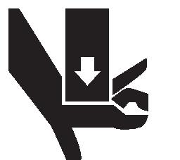
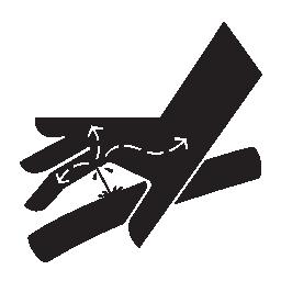
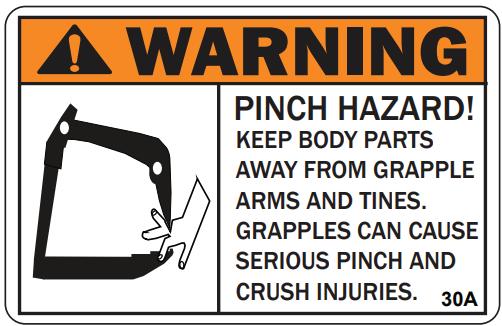
PINCH HAZARD: Keep clear of machine and attachment to prevent death or serious injury from pinching of moving parts.
FLYING DEBRIS HAZARD: ONLY operate this attachment using a machine that has a shatter proof cab to prevent death or serious injury from objects being thrown.
OPERATING MANUAL: Operators must read and understand the safety instructions in the operating manual to prevent death or serious injury.
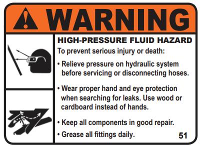
EYE PROTECTION & CARDBOARD: Operators and Maintenance personnel must wear proper eye protection and use cardboard or wood to investigate hydraulic leaks to prevent death or serious injury from being injected with high pressure hydraulic fluid.
HIGH PRESSURE FLUID INJECTION HAZARD: Operators and Maintenance personnel must not place fingers or hands directly over a hydraulic leak to prevent death or serious injury from being injected with high pressure hydraulic fluid.
NO BYSTANDERS: DO NOT operate this attachment near bystanders. Bystanders must stay back at least 300 feet from the attachment to prevent death or injury from objects being thrown.
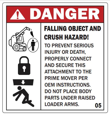
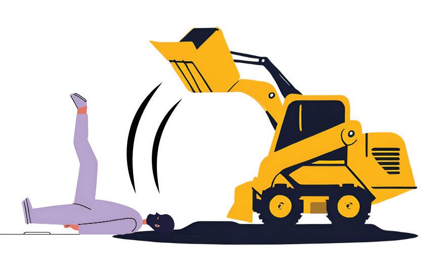
CRUSH HAZARD: DO NOT place any part of the body under the attachment or machine to prevent death or serious injury from being crushed .
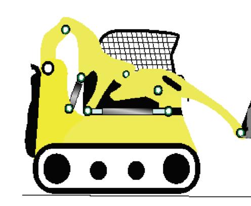
3.3 Safety Decal Locations
Safety warning decals are located on this attachment near immediate areas of potential hazards. Operators must learn the meaning of each decal and know where to find the decal on the attachment.
The safety decals affixed to this machine are to keep you safe. DO NOT ignore these decals.
Read and understand each decal’s safety message. Follow these Safety Decal Instructions:
*WHEN ORDERING, CHOOSE THE PROPER DECAL FOR YOUR MODEL
CONTACT YOUR LOCAL DEALER TO ORDER REPLACEMENT DECALS
Decals must be kept clean and legible at all times.
Operators must inspect the attachment for safety decals.
Replace missing, worn or damaged decals immediately.
When using a hot pressure washer to clean this attachment make sure water jet is not too close to the decal as this may cause the decal to peel.
When replacing parts, be sure safety decals are in place prior to using the attachment.
Make sure metal surface is dry and free of dirt and grease before affixing decals to this attachment.
3.4 Skid Steer Loader Requirements
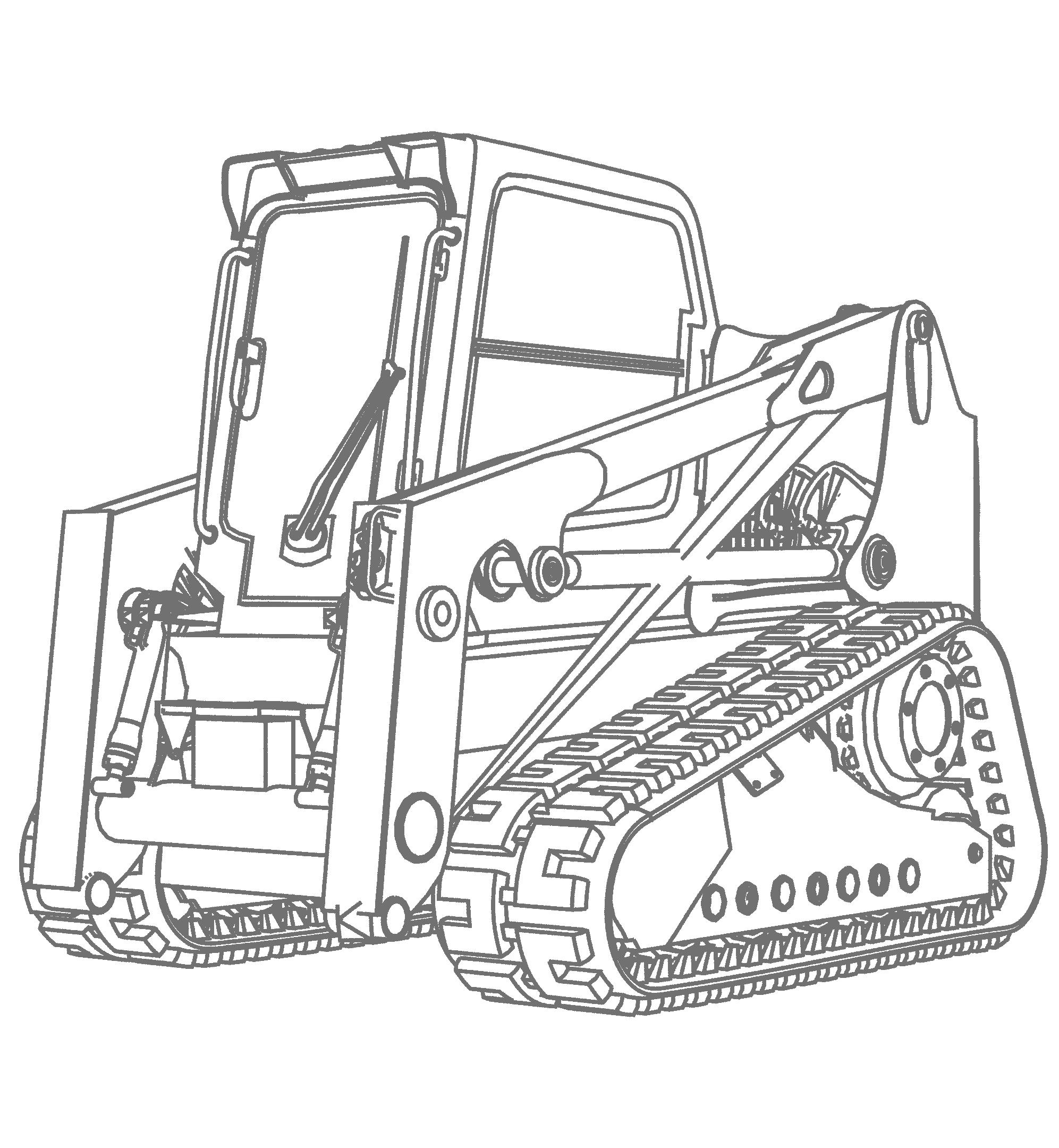
A Tracked Skid Steer or Compact Track Loader (CTL) will provide superior stability in this application.
Make sure your machine is in good operating condition. Follow the operating instructions found in the operator’s manual. Failure to do so could result in minor or serious injury.
Consult the host machine’s rated operating capacity to ensure you have the proper lift capacity for optimal oper ation of your attachment. Flow range MUST support the attachment.
3.5 Personal Protective Equipment (PPE)
All operators should wear hearing protection, safety glasses, hand protection and dust mask while operating this attachment.
Make sure you follow the general safety instructions that relate to the overall operation and maintenance of this attachment. It is important that you read and understand each of these messages to prevent serious injury or death.
NEVER use drugs or alcoholic beverages while operating or servicing this attachment.
ALWAYS operate this attachment during daylight or well-lit areas.
We recommend using a high strength clear protective door panel when using with this attachment.
To prevent the machine and attachment from rolling forward, stop the engine and set the parking brake when exiting the machine.
Inspect attachment for loose or missing hardware prior to using this machine.
ALWAYS watch for overhead power lines.
DO NOT place any part of your body under this grapple.
NEVER operate this attachment when bystanders are within 300 feet of your work area. Falling debris could cause serious injury or death.
NEVER position your body or limbs under an unsupported attachment.
DO NOT allow this attachment to contact buildings, utilities, large rocks or tree stumps or you may lose control of the machine.
DO NOT allow children to play on or around this attachment at any time. Store this attachment in an area not frequented by children.
ALWAYS wear the proper personal protection equipment while operating or servicing this attachment. NEVER operate or service this attachment with bare feet, sandals, or other light footwear.
ALWAYS wear work gloves when handling this attachment to protect your hands.
ALWAYS use eye protection while operating or servicing this attachment.
DO NOT operate this attachment during lightning or severe weather conditions.
DO NOT allow riders on the machine or on this attachment.
ALWAYS call 811, the “Digger’s Hotline” before digging to identify underground utilities to avoid an accident that could result in Death or Serious Injury to the operator.
DO NOT speed! Speed Kills! Keep your driving speed between 2 and 5 mph.
IMPORTANT FEDERAL LAWS AND REGULATIONS CONCERNING EMPLOYERS, EMPLOYEES, AND OPERATORS
This section is intended to explain in broad terms the concept and effect of the following federal laws and regulations. It is not intended as a legal interpretation of the laws and should not be considered as such.
U.S. PUBLIC LAW 91-596 (The Williams-Steiger Occupational Safety and Health Act of 1970) OSHA
This Act Seeks:
“ ... to assure so far as possible every working man and woman in the nation safe and healthful working conditions and to preserve our human resources... ”
Sec. S(a) Each Employer – DUTIES
( 1) shall furnish to each of its employees employment and a place of employment which are free from recognized hazards that are causing or are likely to cause death or serious physical harm to its employees.
( 2) shall comply with occupational safety and health standards promulgated under this Act.
(b) Each employee shall comply with occupational safety and health standards and all rules, regulations, and orders issued pursuant to this Act which are applicable to his or her own actions and conduct.
OSHA Regulations
Current OSHA regulations state in part: “At the time of initial assignment and at least annually thereafter, the employer shall instruct every employee in the safe operation and servicing of all equipment with which the employee is, or will be involved.” These will include (but are not limited to) instructions to:
Keep all guards in place when the machine is in operation;
Permit no riders on equipment;
Stop engine, disconnect the power source, and wait for all machine movement to stop before servicing, adjusting, cleaning, or unclogging the equipment, except where the machine must be running to be properly serviced or maintained, in which case the employer shall instruct employees as to all steps and procedures which are necessary to safely service or maintain equipment.
Make sure no one is within 300 feet of machinery before starting the engine, engaging power, or operating the machine.
EMPLOYEE MACHINE OPERATING INSTRUCTIONS:
1. Securely fasten your seat belt if the machine has a safety operating system.
2. Where possible, avoid operating the machine near ditches, embankments, and holes.
3. Reduce speed when turning, crossing slopes, and on rough, slick, or muddy surfaces.
4. Stay off slopes too steep for safe operation.
5. Watch where you are going, especially at row ends, on roads, and around trees.
6. Do not permit others to ride.
7. Operate the machine smoothly - no jerky turns, starts, or stops.
8. Hitch only to the drawbar and hitch points recommended by machine manufacturers.
9. When machine is stopped, set brakes securely and use park lock if available.
Child Labor Under 16 Years Old
Some regulations specify that no one under the age of 16 may operate power machinery. It is your responsibility to know what these regulations are in your own area or situation. (Refer to U.S. Dept. of Labor, Employment Standard Administration, Wage & Home Division, Child Labor Bulletin # 102).
SECTION 4
OPERATING PROCEDURES
Your attachment arrives from the factory strapped to a wood pallet and requires no final assembly.
Use a steel band cutting tool to remove the steel straps.
Shipping straps are under great tension, and could lash out uncontrollably when cut causing injuries to your body or bystanders. Keep bystanders away and wear safety glasses and gloves while removing the steel straps.
4.1 Pre-Operating Checklist
Pre-Operating Checklist
Grapple is securely attached to the machine and pins are locked.
Hydraulic hoses are connected and locked to the host machine’s hydraulic couplers with no signs of hydraulic fluid leaks present.
□ Grapple is in working condition and securely attached to the machine and all bolts and nuts are tight.
Safety labels are present and legible. □ No material, rope, wire, etc. is obstructing the machine or grapple.
The area of operation is clear of bystanders and any obstacles that could damage the equipment or injury to the operator. □ The operator is of good health and not under the influence of any mind altering substances or alcohol.
Check the machine’s hydraulic fluid level and add manufacturer recommended fluid if necessary. Please refer to our “Hydraulic Fluid and Oil Statement” on Page 5 for gear oil or hydraulic fluid instructions.
General Attachment Method
Refer to your machine’s manual for specific instructions on how to connect and disconnect your attachment. See figure 4.2c.
This attachment method refers specifically to skid steers. For all other attachment instructions, refer to the Original Equipment Manufacturer (OEM) for instructions.
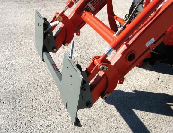
1. Make sure the hydraulic lines are clear from the front side of the grapple’s attachment plate and that the locking pins on the skid steer quick attach mechanism are in the unlocked position.
2. Drive the skid steer to the attachment plate and tilt the skid steer coupler forward and hook the top edge of the skid steer quick attach mechanism under the lip of the grapple’s attachment plate. See figure 4.2a below.
3. Slowly raise and tilt back the skid steer mounting plate, moving upward until the grapple’s attachment plate is flat against the skid steer quick attach mechanism. See figure 4.2a below.
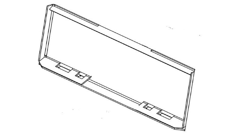
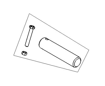
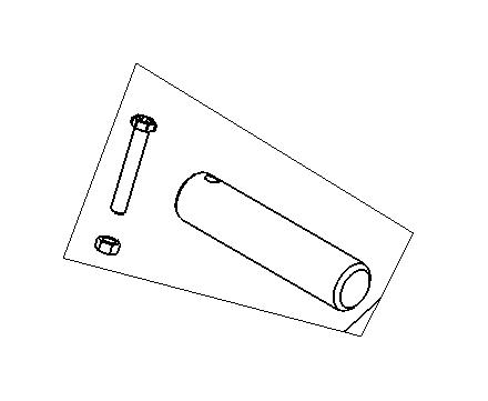
Attachment Mounting Flange
4. Activate your skid steer’s lever lock switch to engage and lock the pins into the flange slots of the grapple’s attachment plate. If your skid steer does not have this switch, push the latch handles down until you can see the lock pins extend into the attachment flange as shown in Figure 4.2b below.
Ensure lock pins fully extend into the attachment flange slots.
To avoid serious injury or death, ensure coupler pins fully extend through the slots on the attachment bracket and that levers are down in the locked position to prevent grapple from detaching from machine.
To keep contaminants from entering the hydraulic system, use a clean cloth to wipe away dirt and grease from the hydraulic couplers and cover with plastic or metal caps when not in use.
5. Connect the attachment hydraulic hoses to the auxiliary supply couplers located on your skid steer loader lift arm.
Check that hydraulic hoses are locked into the machine’s couplers before moving the grapple.
ALWAYS visually inspect and verify that the coupler lock pins are fully engaged through the latch slots on the attachment plate.
NEVER enter the area underneath the coupler or any part of the attachment when it is in the raised position to avoid an accident that will result in Death or Serious Injury!
4.3
Connecting Electrical Harness
Connect the 2-wire control harness from the attachment using the A or B Method as shown on page 26. A universal, 7, 8, or 14 pin pigtail harness adapter is available to make this connection. When using the optional switch controller, make sure the ground wire is securely attached to the machine frame. Contact your local dealer for more information on how to connect the harness and controller.
Your grapple is designed to run off the machine’s auxiliary hydraulic system, and is activated and deactivated by a control in the operator’s cab. The height and tilt functions as well as the opening and closing functions of your grapple are operated with the control handles or pedals in the cab. Consult your machine operator’s manual for instructions regarding these functions. Grapple Controls
Line points to 2 wire plug.
4.5 UNIVERSAL CONTROLLER INSTALLATION
To prevent possible equipment damage, it is recommended that the universal controller is installed by a qualified technician who is familiar with your machine’s electrical system.
1. Place the control box inside the machine cab and connect the red wire with the fuse to the machine operator presence system and the black wire to the machine’s grounding system.
Ensure proper functionality of the machine’s operator presence system. In the event that bypassing is necessary while utilizing a wiring harness, your use implies acknowledgment and acceptance of inherent risks to yourself and others. Your usage constitutes acceptance for full liability.
2. Route the control cable that extends from the right side of the controller box through the side of the cab and up to the back of the loader pivot arm, then down the arm to a point near the bulkhead coupler. Secure cable with plastic cable ties or velcro straps.
3. Check that the cable is free of tension when raising and lowering the machine loader arms.
Some machines have a “float” function on the lowering circuit which will allow the attachment to follow the contour of the ground being worked. See the machine’s operator manual for instructions.
Optional Universal Switch Controller
Universal Adapter
4.6 How to Disconnect Grapple
1. Turn off auxiliary hydraulic circuit; relieve hydraulic pressure.
2. Park machine on a flat and level surface then lower grapple to the ground.
3. Set parking brake and disengage lock pins using the lock lever switch (if installed).
4. Turn off machine engine.
5. Disconnect hydraulic hoses.
6. Pull latch handles to disengage lock pins.
7. Re-enter cab and start machine engine.
8. Tilt mounting coupler forward until Quick Attach Coupler is free from mounting bracket.
9. Drive machine backward to clear attachment.
4.7 Hydraulic System
Please refer to our “Hydraulic Fluid and Oil Statement” on Page 5 for gear oil or hydraulic fluid instructions.
HYDRAULIC FLOW
When operating the grapple, set the machine engine RPM to a speed that will produce the required flow. Your machine dealer can measure the flow available on your machine and recommend a throttle setting that is compatible with this attachment.
DO NOT EXCEED the designated flow rate (GPM).
If the hydraulic function operates in the opposite direction than preferred, change the positions of the quick disconnect couplers on the attachment hoses to remedy the problem.
ALWAYS release the hydraulic system pressure from the hydraulic circuits prior to removing the attachment or any hydraulic service work.
ALWAYS contact 811, the “Digger’s Hotline” to identify underground utilities to avoid an accident that could result in Death or Serious Injury!
ALWAYS be aware of your surroundings and pay attention to obstacles and terrain around you.
You must notify utility companies of your intent to dig or trench by calling 811 or making an online request with your state’s 811 center a few days prior to digging or trenching. Visit: https://call811.com/811-In-Your-State to connect to your state’s 811 center.
4.9 PREPPING FOR First time Use
Verify that hydraulic hoses are securely locked to the machine hydraulic couplers before starting to use this attachment.
Before operating the grapple, check the hydraulic fluid in the machine and add fluid if necessary.
Please refer to our “Hydraulic Fluid and Oil Statement” on Page 5 for gear oil or hydraulic fluid instructions.
1. After starting machine, lift attachment ten (10) inches off the ground surface:
2. Set machine engine RPM to just above idle.
3. Slowly engage the auxiliary hydraulic flow to the attachment cylinder arm until the function operates.
4. Reverse the direction of the hydraulics until the function has been placed in the opposite direction. Repeat this two (2) more times to purge any air from the system.
5. Lower the attachment to the ground, shut off machine engine and exit the operator ’s cab.
6. Check the hydraulic fluid level in the machine, add manufacturer recommended fluid if necessary.
7. Inspect the grapple hydraulic lines & connectors for noticeable leaks. Fix before continuing
To avoid serious injury by hydraulic fluid injection into your skin, never use your hand or other body parts to locate a hydraulic leak. Detect leaks with a piece of wood or cardboard.
4.10 LEARNING YOUR ATTACHMENT
NEVER operate the attachment when bystanders are within 300 feet of your work area.
USE CAUTION when operating on un-level ground surfaces. A machine roll over could result in Minor or Serious Injury. ALWAYS wear your seat belt when operating this attachment.
1. Before using this attachment, make sure you are knowledgeable and comfortable with the operation of the auxiliary hydraulic control as outlined in previous sections of this manual and in the machine’s operator’s manual.
2. When operating this attachment, set the machine throttle at a speed that will produce the required flow. If the machine is equipped with a foot throttle, use it to control engine speed and power being delivered to the attachment. Refer to your machine manual or call your local machine dealer for additional help if necessary.
3. Learn what the attachment looks like in a level position when you are seated in the machine. This will help you when operating the attachment.
4. The correct ground speed while using this attachment depends on the application and condition and can usually be monitored by sound and feel and depends on the material density.
5. Note that if the machine engine is bogging down because of load on the attachment, it will be necessary to decrease the load until the machine’s power can overcome the material load on the attachment.
4.11 BEFORE USING YOUR ATTACHMENT
ALWAYS contact 811, the “Digger’s Hotline” to identify underground utilities to avoid an accident that could result in Death or Serious Injury!
EXPOSURE to crystalline silica dust along with other hazardous dusts may cause serious or fatal respiratory disease. It is recommended to use dust suppression, dust collection and if necessary personal protective equipment during the operation of any attachment that may cause a high level of dust.
1. Inspect the area to be worked and make sure it is free of any utilities, rocks, fence posts, or any other objects that you do not want to move.
2. Determine a safe and efficient pattern before the start of the job.
To prevent death from electrocution, NEVER operate this attachment near electrical wires or cables.
When lifting a load of brush or trees, make sure all ends are not tangled with standing trees that could cause the center of gravity to be compromised, resulting in a rollover that could cause Death or Serious Injury.
1. ALWAYS inspect the work area before starting the job. Locate and mark any utilities (also turn utilities off), steel posts, rocks or any other objects that could be damaged or could damage this attachment during operation.
2. NEVER assume the work area is safe and skip the inspection before start of operation.
3. Operate at a safe slow-paced speed that will allow you to watch the area ahead and behind the attachment and machine.
4. Since about half of your work with this attachment may be in reverse, look behind you and/or utilize your mirrors and back-up camera when backing up.
5. VERIFY that your back-up alarm and camera are working properly to warn others when you are in reverse, but NEVER think that the alarm or camera replaces your responsibility to visually check what is behind you.
6. Attachment control is the most important element to getting a good steady work flow. Overloading the attachment will only result in spinning the tracks or tires and will make unwanted ruts.
7. Overloading the attachment will also necessitate raising the implement to offload some of the resistance occurring by the material.
8. If you lift too heavy a load with your attachment, you may raise the rear of your machine, and further reduce your tractive power available to move the load.
9. Before beginning your forward motion with your attachment, stop the machine and make any final adjustments to the attachment for weight and height.
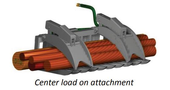
10. When picking up objects with your attachment, make sure you center your load. Estimate the load center and pick up accordingly, reposition your grab and retry if needed. An unbalanced load could flip your machine.
11. When loading your hydraulic attachment and clamping the arms over the load, roll the attachment back and retighten the clamp arm pressure. The load will settle
and require some additonal clamping pressure to secure the load.
12. When using your hydraulic attachment, make sure that you can visually see your load. Beware of pushing or pulling down trees or any type of structure in which you cannot visually see the process.
13. To save service work and down time, always pay attention that tree branches or roots do not poke through past the attachment arms and damage any hydraulic parts or even enter the cab area.
14. Be careful that a branch or root does not “whip” back at the machine. Wear safety glasses to prevent dirt getting in your eyes. The manufacturer highly recommends a closed in cab.
15. Keep your distance from any type of utility, whether underground or in the air.
SECTION 5
MAINTENANCE PROCEDURES
The maintenance procedures described in this manual should only be carried out by qualified mechanics who have been trained to repair this attachment.
Some procedures require special tools and skills to complete. DO NOT attempt to repair or perform service work on this attachment unless you have the skills and tools to do so. Contact your local dealer for maintenance and repair services.
Parts
Only use genuine MANUFACTURER replacement parts on this attachment. We will not be liable for any damages or injuries caused by the use of after market parts on this attachment.
Improper maintenance or modifications to the design or performance of this attachment will void the warranty. ONLY use genuine replacement parts on this attachment.
Obey the following safety instructions when servicing or repairing this attachment
Wear proper Personal Protective Equipment (PPE) while working on this attachment, which may include safety glasses, hard hats, steel toe boots, gloves, etc.
If servicing is performed while the grapple is attached to the machine, turn engine off, set parking brake and chock wheels to prevent machine from moving.
Ensure all jack stands, lifts and hoists are in good working condition and have the rated load capacity to support the load.
Only perform service work in a well-lit area.
Allow the attachment to cool down before servicing this attachment. Hot oils can burn your skin.
NEVER work under an unsupported attachment.
5.1 Maintenance schedule.
This Grapple attachment will provide years of dependable service if routine maintenance procedures are performed. The maintenance tasks listed below are based on normal operating conditions. More frequent maintenance may be necessary with intense use or when operating in adverse environmental conditions.
Some of these maintenance tasks may not apply based on your grapple model.
Check host machine’s hydraulic fluid level. Add manufacturer recommended fluid as necessary. Please refer to our “Hydraulic Fluid and Oil Statement” on Page 5 for gear oil or hydraulic fluid instructions.
Check that all fasteners (nuts, bolts, washers, pins, keepers) are in place. Tighten as necessary.
Inspect and replace any worn, torn, or missing safety decals.
Inspect hydraulic hoses and connectors for damage or leakage. Repair or replace hydraulic items as necessary.
Lubricate all pivot joints using #2 lithium grease.
Check the condition of the cutting edge.
Check grapple for major scratches & dings. Sand and repaint these areas to prevent rust damage. *Use paint formulated for farm equipment which can be found at your local hardware store.
Document all maintenance and service activities performed on this grapple using the maintenance log sheets included at the end of this manual.
5.2 CUTTING EDGE REMOVAL & REPLACEMENT
NEVER enter the area underneath the coupler or any part of the attachment when it is in the raised position to avoid an accident that will result in Death or Serious Injury!
Hazardous dust can be generated if painted surfaces are heated or welded and could result in Death or Serious Injury. Remove paint before welding and always make repairs in a well-ventilated area and wear an approved respirator.
Bolt-on cutting edge replacement can be completed safely with proper torque values applied.
Weld-on cutting edge replacement is not a task for most machinery operators and should be referred to a welding shop that possesses the proper equipment, knowledge, and experience. Replacement cutting edges are available from the manufacturer.
Cutting edges can be very heavy and could cause Minor or Serious Injury if mishandled. ALWAYS wear protective gloves and footwear.
Welding Repairs
Welding on attachments must be performed by certified welders who have requested and obtained written approval from an authorized representative of the manufacturer before welding begins.
All authorized welding repairs must be performed by qualified welders in accordance to the American Welding Society (AWS) standards. Welding procedures performed by unqualified welders may deem this grapple unsafe to operate and VOID THE WARRANTY!.
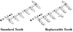
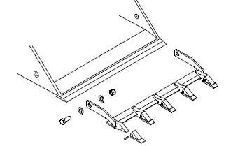
5.3 Tooth bar Installation (Optional)
Optional- Tooth Bar Installation
Attaching a tooth bar to your existing grapple is a simple process. The shanks on the tooth bar hook onto your existing cutting edge where the pressure is applied. The bolts hold the tooth bar to the grapple. The teeth are all replaceable so there is no worry about breaking one.
1. Find the hole on each side of your bucket. If one cannot be located, you may drill one.
2. Bolt on the tooth bar and torque to the specifications listed on page 38.
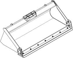
Optional- Cutting Edge Installation
Attaching the Cutting Edge to your existing grapple is a simple process that requires the use of the appropriate bolts and nuts, then torquing to the correct specifications as listed on page 38.
Contact your dealer for help with specific problems.
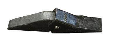
Weld-On Tooth
MAINTENANCE LOG
Use the log sheets on at the end of this manual to document all routine maintenance and repair services performed on this attachment.
5.5 Storage Tips
Ensure grapple is free of debris, dirt and grease.
Store your grapple in a dry shed or garage.
When storing your grapple for the season, cover with a weather proof tarp to protect it from the elements.
5.6 Torque Specification Table and Instructions
Bolt torque INSTRUCTIONS
1. Apply and maintain proper torque on all bolts.
2. Torque values are based on lubricated values. Do not grease or oil bolts.
TORQUE VALUES
SAE GRADE 8
3. Wipe bolts clean and use Loctite 635 or equivalent before tightening bolts. May need curing activator.
4. Use a torque wrench to assure the proper amount of torque is being applied to the bolt.
5. MUST CURE 72 HOURS BEFORE USE TO PREVENT LOOSENING OF BOLTS.
5.7 Torque Equipment Requirements
TOOLS & EQUIPMENT REQUIREMENTS
To complete the maintenance procedures described in this section, you may need the following tools:
• 1/2 inch drive breaker bar
• 3/4 inch impact socket
• 1/2 inch impact socket
• Tapping Hammer
• 1/2 inch drive torque wrench
• Nylon pry bar set
• Safety stands
• Loctite 635 or Equivalent-MUST CURE 72 HRS
• Lifting device (overhead crane hoist, forklift)
When removing bolts with Loctite, it will be necessary to apply localized heat of at least 250 degrees Celsius or to 482 degrees
to loosen bolts.
LOCTITE 635 technical specifications for bonding, curing, removal and installation can be found here:
https://next.henkel-adhesives.com/
Problem
Machine loses power when operating grapple
Troubleshooting SECTION 6
Possible Cause Solution
RPM’s are not high enough.
Hydraulic Flow is too slow or has a leak.
Grapple becomes uneven.
Hydraulic fluid level goes down during operation.
Grapple does not move when hydraulic system is activated.
Hydraulic system leak, or leaks in host machine’s hydraulic system.
Increase RPMs and reduce ground speed.
Look for hydraulic leaks & repair.
Clear the sweeping area of solid objects, raise grapple height to clear exposed rock surfaces.
Use on the correct machine.
Investigate and repair leaks.
Cylinder does not open or close.
Incomplete circuit to & from machine.
Cylinder failure.
Quick disconnects not connected.
Hose damaged.
Machine auxiliary circuit inoperative.
Internal damage to the cylinder.
Restricted hose.
Circuit relief on machine bad.
Cylinder moves very slow
Auxiliary valve spooling on machine not shifting properly.
Cylinder seals by-passing.
Disconnect and reconnect hoses to machine.
Replace cylinders.
Check & Recouple Quick disconnects.
Check for smashed or kinked hose & replace if found.
Investigate and have repaired.
Replace Cylinder.
Check for damaged hose between machine & cylinders. If damaged, replace.
Investigate & have repaired.
Investigate & have repaired.
Have cylinder(s) repacked or replaced.
ONLY service the grapple on stable, even terrain. NEVER park on sloped terrain to avoid being struck & killed or seriously injured by the unexpected rolling or movement of the machine.
parts information SECTION 7
Factory fresh parts specifically designed for your implement are readily available.
For hassle free service and to ensure you receive the correct parts for your implement, please provide your dealer with the following information:
Model Number
Serial Number
GPM Requirements
Date of Owners Manual (Bottom Left Corner of Cover Page)
Parts Diagram Page Number
Part Description
Reference #
Quantity Desired
Ship To Information
Bill To / Payment Information
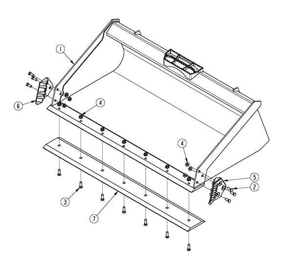
ToothBar & Side cutters Diagram
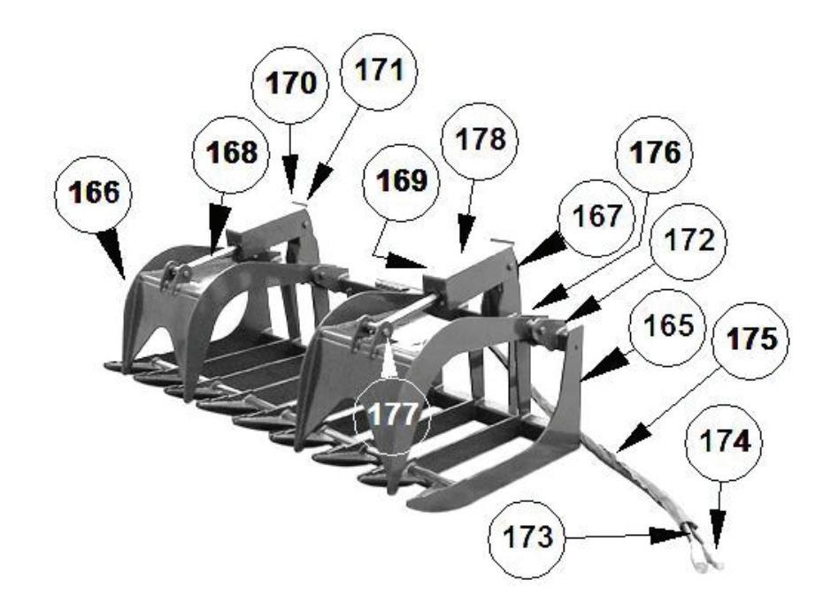
72” X-Treme Rake Grapple With Teeth
P A R T S L I S T D E S C . P A R T # Q T Y I T E M 1 / 4 " D X 7 ' L M a c h i n e H o s e 5 2 8 0 0 0 2 6 1 1 1 3 / 8 " F
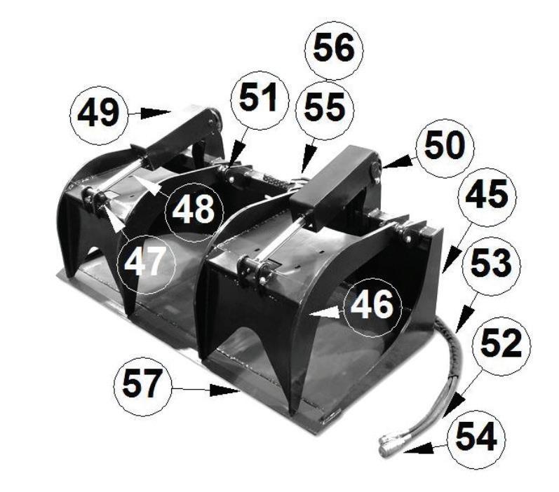
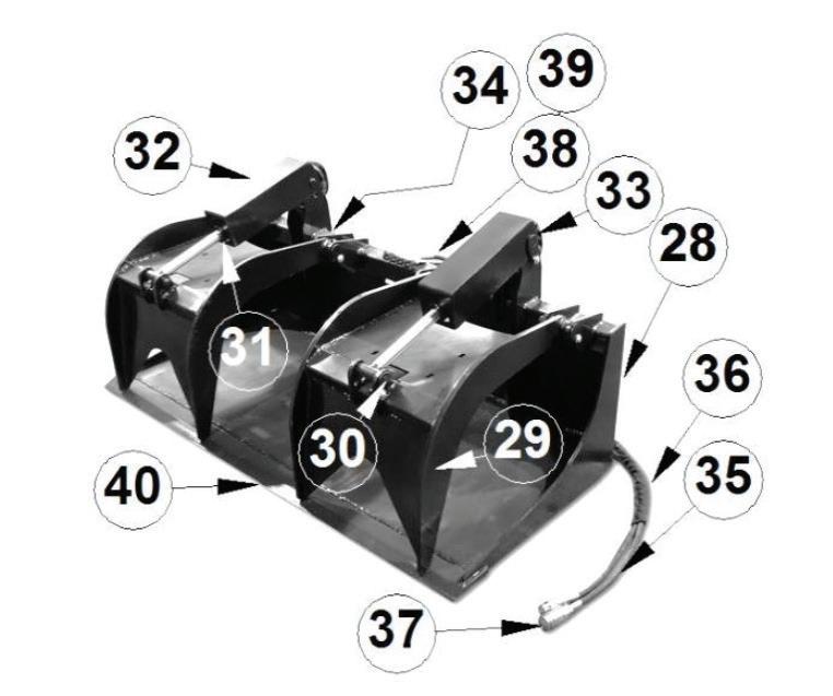
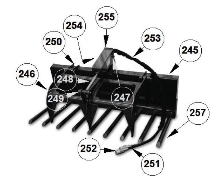
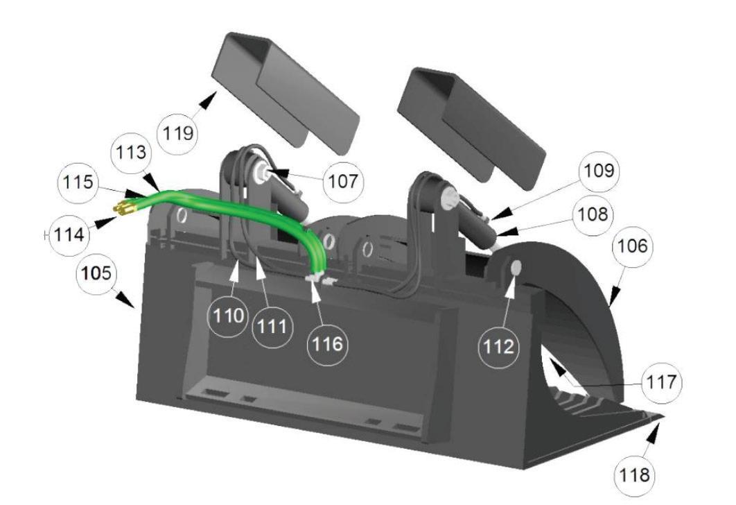
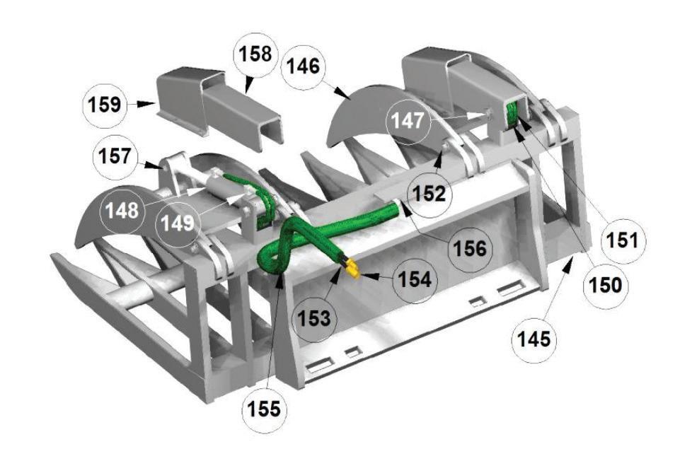
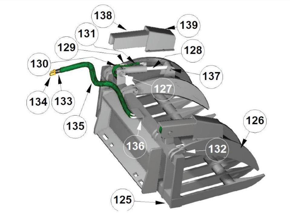
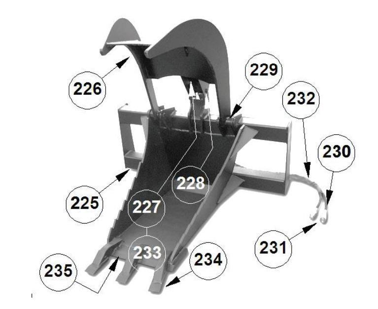
7.17 X-TREME Rock Grapple Detailed Diagram
81” X-Treme Rock Grapple
Warranty Information SECTION 8
LIMITED WARRANTY
LACKENDER products are warranted to be free from defects in workmanship or materials for a period of 12 months from the initial sale.
Warranty Exclusions
This warranty does not cover normal wear items, including but not limited to: bearings, hoses, blade holders, ground engaging parts such as teeth, blades, cutting edges, pilot bits, auger teeth and broom bristles. This warranty does not cover maintenance, service or adjustments. This warranty does not cover damage due to improper application or installation, misuse, negligence, accidents or improper maintenance. Please note: Any modification or customization made to your attachment may void its warranty. This warranty is void if any components have been disassembled, i.e., pumps, gear boxes or motors or the attachment has been used without the case drain attached (if applicable). Be sure to follow all recommended Horsepower and GPM requirements as outlined in product specifications, in order to prevent the warranty from being void. This warranty is contingent upon the use of approved BRAND parts exclusively. Any use of non-approved parts may result in voiding the warranty. Please be advised that the warranty does not cover refurbished attachments. Specially modified attachments built by the manufacturer to meet your needs shall not be warranted by Lackender.
REPAIRS UNDER WARRANTY
Any repairs, including welding, on attachments must be performed by certified repair technicians who have requested and obtained written approval from an authorized representative of the manufacturer before repairs begin. If you are completing the repair, you must also have prior written approval to prevent the warranty from being voided.
Warranty Statement
Our obligation under this Limited Warranty shall be solely limited to repairing or replacing any part (see noncovered items above) that, according to our judgment, show evidence of a defect in quality of workmanship or materials for the stated 12 month warranty period. All defective parts must be routed directly to Lackender with
freight or delivery charges to be prepaid. This limited warranty shall not be interpreted to render Lackender liable for any injury or damage to persons, businesses or property of any kind nor expenses or losses incurred for labor, supplies, substitute machinery rental or for any other reason. Repair or replacement parts are subject to the supply conditions at the time of repair or replacements, which may directly affect our ability to obtain material and/or replacement parts. Lackender reserves the right to make improvements in design or changes in specifications at any time without incurring any obligations to owners of previously purchased products. No one but Lackender is allowed to alter, modify or enlarge this warranty nor the exclusions, limitations and reservation at any time. Lackender products are warranted to be free from defects in workmanship or materials for a period of 12 months from the initial sale.
Purchaser and Manufacturer hereby (a) submit to the non-exclusive jurisdiction of the courts of competent jurisdiction in the state and county in which this company resides for resolution of any dispute concerning this Limited Warranty or the rights or obligations of Purchaser and/or Manufacturer; (b) agree that any litigation in connection with this Limited Warranty shall be venued in the state and county in which the company resides and (c) waive any objection they may have as to any such action or proceeding brought in such court that such court is an inconvenient forum. Nothing herein shall limit the right of Purchaser or Manufacturer (or the right of any permitted successor or assign of either) to bring proceedings against the other in the courts of any other jurisdiction wherein any assets of such other party may be located.
This warranty and return policy is governed by the current policies posted on the manufacturer’s website.
8.1 warranty Return Authorization Policy
Warranty Return Authorization Policy:
If repairs are required, Lackender must obtain a Return Material Authorization (RMA) number from the manufacturer of the defective part and proof of purchase. RMA and services are rendered by Lackender only. Any responsibility of shipping costs on any item returned for repair is at the discretion of Lackender.
All returned parts must have the following:
1. A legible RMA number written on the outside of the package.
2. Warranty Claim Form (online)
3. The defective part.
RMA numbers are only valid for 30 days from the date of issue. All shipped replacement parts may require a Parts Order (PO) number from the original Lackender dealer. Repairs not covered by the warranty, will be charged for parts and labor at the current pricing rate. Should you have any problems with your attachment, please follow the instructions listed on the following page.
8.2 warranty Procedure
Warranty return authorization procedure:
1. For Warranty Concerns please contact your local dealer. You will need to provide the model and serial number of the defective item(s), (See Appendix B: Where to find the model & serial number) a description of the problem, and have photographs available.
2. Upon a warranted issue, visit www.ecsattachments.com, click on the warranty tab, and fill in the warranty information on the Warranty Claim Form.. Lackender will retain a Return Material Authorization (RMA) number from the manufacturer of the defective part. If all the information above is completed the manufacturer will issue a RMA number via email..
3. Once you have an approved RMA number, a shipping label will be provided with the manufacturer’s address and instructions for returning the defective part. Appropriate RMA/ PO’s will be invoiced and payment received while the evaluation process is being completed to prevent delays in your normal business operations. In the event the defective part(s) is un-warranted and repairs are not covered by the warranty, the customer will be invoiced for any additional parts and labor at the current pricing rate. If the part is deemed under warranty, a credit of the invoice will be issued.
4. Lackender will ship a replacement part to the provided location or customer, with a RMA identifier of some kind. The customer is responsible for initial shipping charges until evaluation of the part has been completed. If the part failure is covered by the warranty, the customer will be reimbursed for any paid shipping charges. In the event, the part is not covered by the warranty, the customer is responsible for return shipping.
5. Once the defective part is warranted by the manufacturer, the customer will be issued a credit and the PO number will no longer be active.
6. In the event the manufacturer decides that the attachment needs to be returned to the manufacturer for repair, Lackender will make arrangements for pickup and return. Repairs will be performed by qualified technicians. Non-warranted issues will be discussed, and repairs will be performed upon the owner’s agreement and receipt of payment for parts and labor.
SECTION 9
Safety Acknowledgment
ATTENTION ALL OPERATORS: Print your name, sign and date in the boxes below to acknowledge that you have read and fully understand the safety instructions presented in this manual, and have been trained on how to safely operate this attachment.
Operator Name Signature Date
MAINTENANCE Logsheets
Use this log sheet to document all routine maintenance and repair services performed on this attachment.
Description of Maintenance/repair Serviced by: DAte:
MAINTENANCE LOG
Use this log sheet to document all routine maintenance and repair services performed on this attachment.
Description of Maintenance/repair Serviced by: DAte:
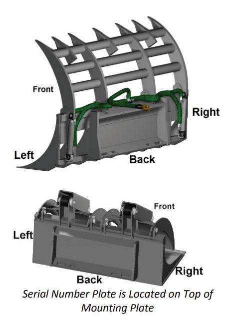
Appendix A Finding your model and serial number
The Model and Serial numbers will be in one place and will either be etched into the attachment or on a Data Plate.
Instructions: Stand at the back of the attachment facing the attachment mounting bracket and look in the following locations:
1) Back- top left area
Model and Serial Number
Data Plate
PLEASE NOTE: The Model and Serial number may be etched or on a Data Plate.
Disclaimer: Any critical changes made to this manual by individuals outside the manufacturer’s authorized personnel are doing so at their own risk. The manufacturer cannot be held legally responsible for any consequences, damages, or liabilities resulting from such modifications.
It is advised to adhere strictly to the original manual provided by the manufacturer for optimal performance, safety, and reliability.