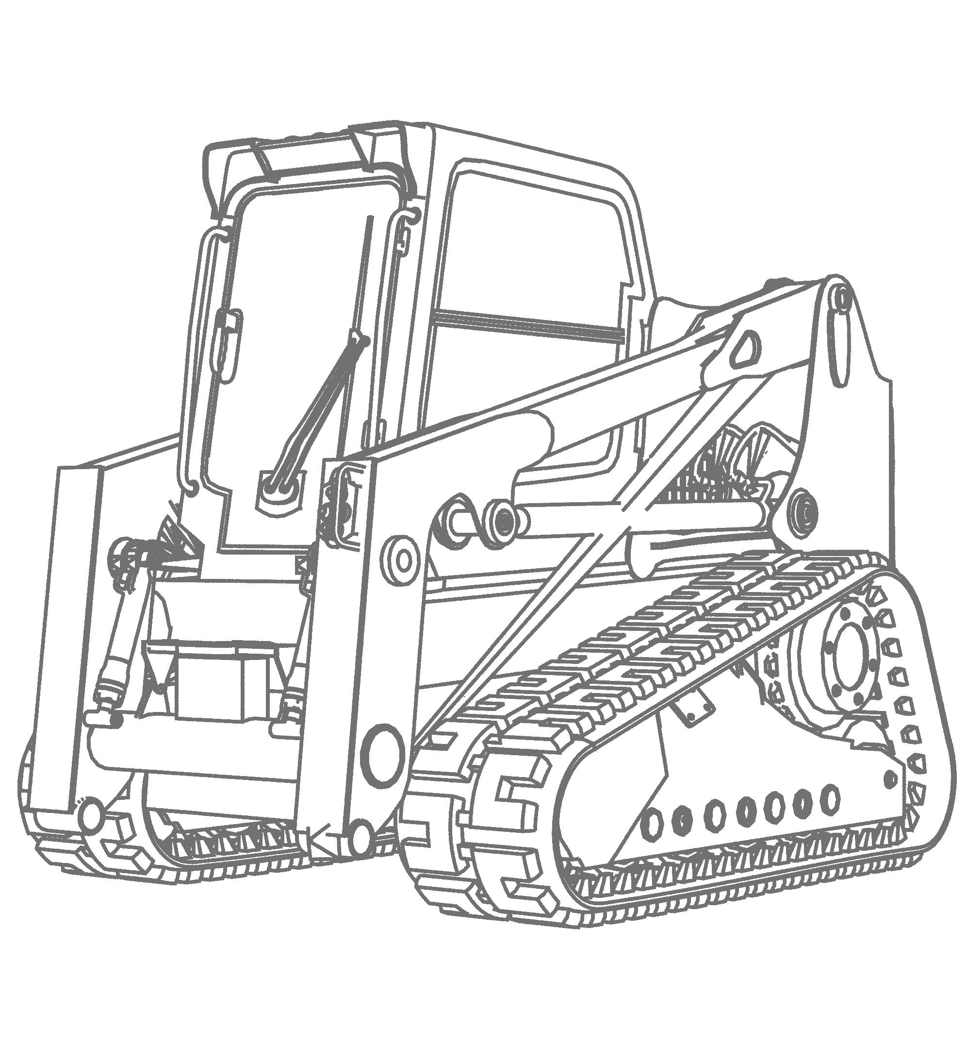
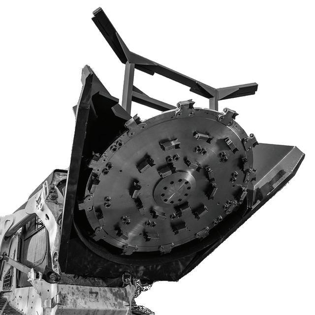
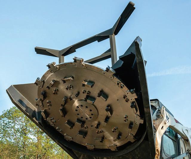
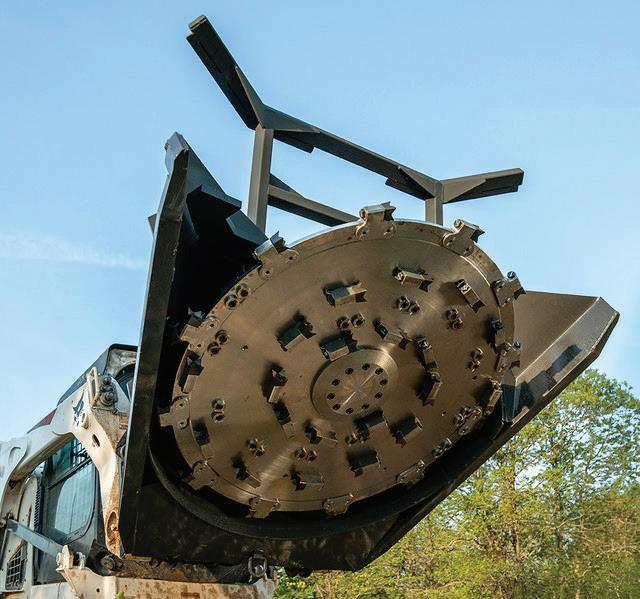
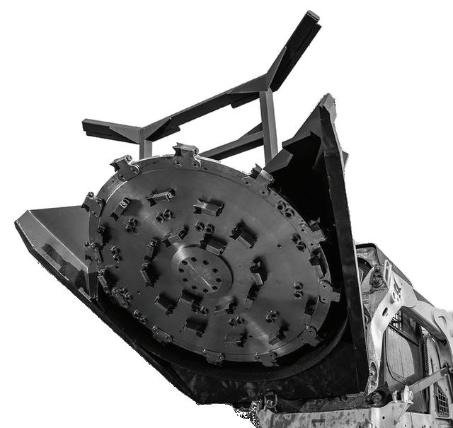
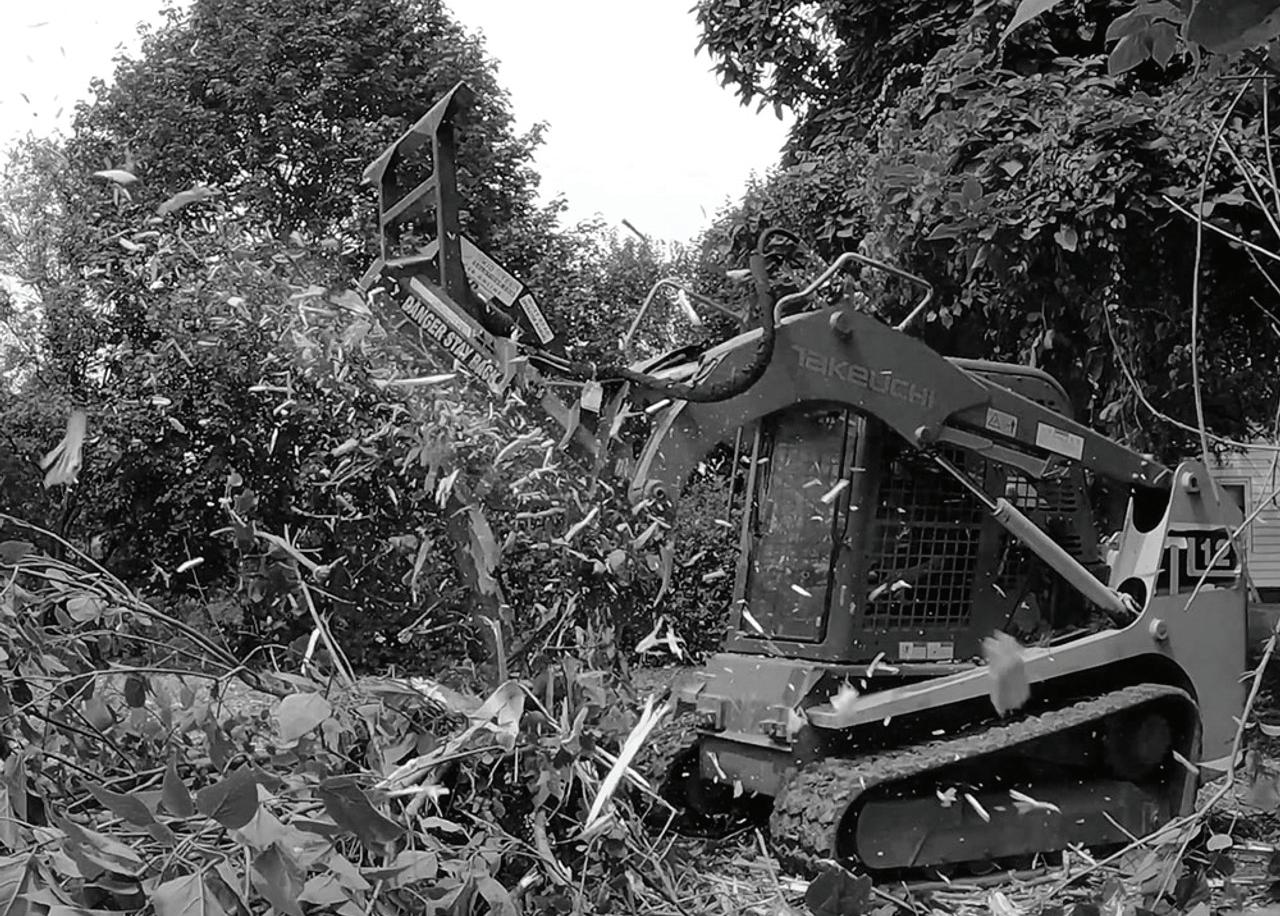
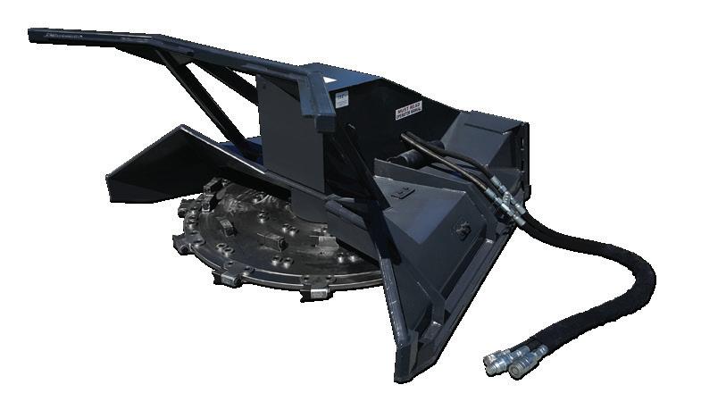
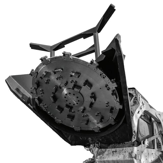
Forestry Disc Mulcher
Please see the inside of the back cover for instructions of where to find your model and serial number.
To prevent personal injury or even death, be sure you read and understand all the instructions in this manual and other related OEM equipment manuals! This attachment, if not used and maintained properly, can be dangerous to users unfamiliar with its operation. Do not allow operating, maintaining, adjusting, or cleaning of this attachment until the user has read this manual and has developed a thorough understanding of the safety precautions and functions of the unit. This attachment is designed for the purpose specified. DO NOT modify or use this attachment for any application other than that for which it was designed. Attachments maintained or operated improperly or by untrained personnel can be dangerous, exposing the user and/or bystanders to possible serious injury or death.
Purchase Date:
Dealer Name:
Address:
Phone Number:
Thankyou for choosing Lackender. This attachment has been designed and manufactured to meet the needs of discerning users. We are committed to providing you with a heavy duty

Copyright © 2024, ECS Attachments.. All Rights Reserved. This manual may not be reproduced or copied, in part or in whole without written permission from ECS Attachments.
/ SECOND EDITION /OCT 2024 APPROVAL: David Hale
TABLE OF CONTENTS
SECTION 3 OPERATING PROCEDURES
SECTION 4 MAINTENANCE PROCEDURES
SECTION 5 TROUBLESHOOTING
7.0
IMPORTANT Warranty Disclaimers
ATTENTION: If your attachment has control valves, cylinders, gearboxes, or motors and they are opened or disassembled, the WARRANTY for that item WILL IMMEDIATELY BE VOIDED!
GEAR OIL STATEMENT: If applicable in your attachment, check gear oil before each use: We recommend using Shell Omala S2 GX 150 grade gear oil, for use only with mulcher gear boxes, and bearing housings which is separate from the hydraulic fluid used to move your attachment or machine. (PLEASE NOTE: All our other gear boxes use 85-140 grade gear oil)
HYDRAULIC FLUID STATEMENT: Check your machine’s hydraulic level and add hydraulic fluid if necessary before each use. Inspect for leaks, and repair if necessary. Always use your machine’s manufacturer recommended hydraulic fluid in your machine! Fluid must be clean and debris free. If damage occurs from debris in hydraulic fluid flowing from your machine to our attachment it will VOID the warranty on any cylinders, motors, couplers, manifolds &/or valves (relief, lock, selector, check and flow control) downline from that flow.
NOTE: If your attachment requires a case drain, the warranty WILL BE immediately voided if the attachment is ran without it. Please refer to specifications sheet on page 34 of this manual.
SAFETY INFORMATION SECTION 2
The following terms may be used interchangeably throughout this manual.
implement, attachment, mulcher, machine, disc mulcher, cutter
Machine skid steer loader, skid steer tractor, loader, prime mover, host machine, tractor
Operator user, personnel
The Disc Mulcher is designed and manufactured with safety in mind. However, improper use and operator error can result in death or serious injury. It is important that you read and fully understand the safety instructions and operating procedures presented in this manual before operating this attachment. Accident prevention is a combination of good judgment, common sense, awareness and proper training!

BEFORE you operate this Disc Mulcher:
KNOW how to safely operate your machine.
READ and UNDERSTAND the safety instructions and operating procedures contained in this manual.
ACKNOWLEDGE your understanding of all safety instructions presented in this manual by signing the “Safety Acknowledgment Form” at the end of this manual.
Although every effort has been made to ensure a safe product, every possible circumstance that could pose a potential hazard cannot be anticipated. The warnings presented in this manual and on this product, are therefore not all-inclusive.
In addition to the safety messages presented in this section, you must also read and understand the safety messages presented in the other sections of this manual.
Forestry Disc Mulcher
Alternate Terms Used Term
This manual and the decals on this machine use safety symbols, hazard labels, pictograms and color coded signal words to alert you to potential hazards that may cause severe injury or death if a safety instruction is ignored.

SAFETY ALERT SYMBOL - This symbol is used to alert you to potential personal injury hazards. Obey all safety messages that follow this symbol to avoid possible injury or death.
Hazard Classifications
Hazards are identified by the “Safety Alert Symbol” and followed by the signal word “DANGER”, “WARNING”, or “CAUTION”.

Indicates an imminently hazardous situation which, if not avoided, will result in death or serious injury. This signal word is limited to the most extreme situations.

Indicates a potentially hazardous situation which, if not avoided, could result in death or serious injury.

Indicates a potentially hazardous situation which, if not avoided, may result in minor or moderate injury.

Indicates a situation which may cause damage to equipment or property. Messages are not related to personal injury.

Indicates specific safety-related instructions or procedures.
2.2 Safety Symbols
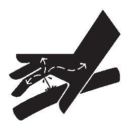
Pictograms are graphic symbols meant to alert you of a potential hazard. Read and understand the hazard description for each of these symbols.
Pictogram
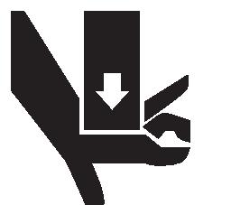


Description
PINCH HAZARD: Keep clear of machine and attachment to prevent death or serious injury from pinching of moving parts.
FLYING DEBRIS HAZARD: ONLY operate this attachment using a machine that has a shatter proof cab and door to prevent death or serious injury from objects being thrown.
OPERATING MANUAL: Operators must read and understand the safety instructions in the operating manual to prevent death or serious injury.
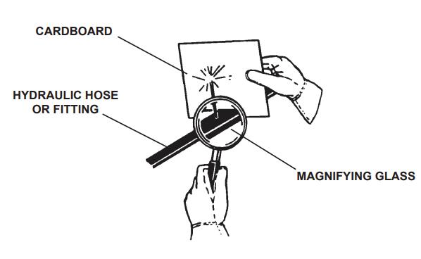
EYE PROTECTION & CARDBOARD: Operators and Maintenance personnel must wear proper eye protection and use cardboard or wood to investigate hydraulic leaks to prevent death or serious injury from being injected with high pressure hydraulic fluid.
HIGH PRESSURE FLUID INJECTION HAZARD: Operators and Maintenance personnel must not place fingers or hands directly over a hydraulic leak to prevent death or serious injury from being injected with high pressure hydraulic fluid.
NO BYSTANDERS: DO NOT operate this attachment near bystanders. Bystanders must stay back at least 300 feet from the attachment to prevent death or injury from objects being thrown.
CRUSH HAZARD: DO NOT place any part of the body under the attachment or machine arms to prevent death or serious injury from being crushed .
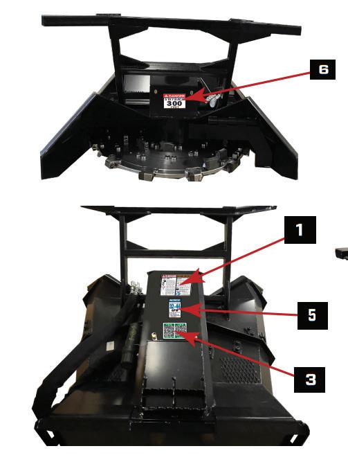
2.3 Safety Decal Locations
Safety warning decals are located on this attachment near immediate areas of potential hazards. Operators must learn the meaning of each decal and know where to find the decal on the attachment.
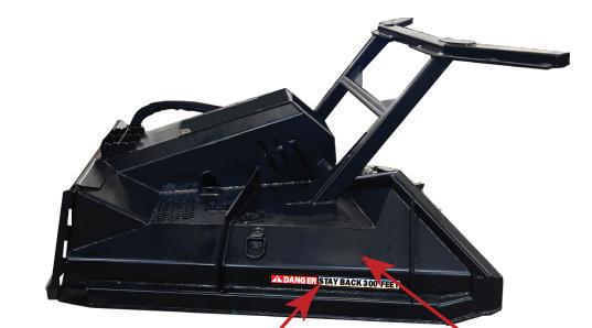
The safety decals affixed to this attachment are to keep you safe. DO NOT ignore these decals.
Read and understand each decal’s safety message. Follow these Safety Decal Instructions: *WHEN ORDERING, CHOOSE THE PROPER DECAL FOR YOUR MODEL


Decals must be kept clean and legible at all times.
Operators must inspect the attachment for safety decals.
Replace missing, worn or damaged decals immediately.
When using a hot pressure washer to clean this attachment make sure water jet is not too close to the decal as this may cause the decal to peel.
When replacing parts, be sure safety decals are in place prior to using the attachment.
Make sure metal surface is dry and free of dirt and grease before affixing decals to this attachment.
2.4 Skid Steer Loader Requirements
A Tracked Skid Steer or Compact Track Loader (CTL) will provide superior stability in this application.
Follow the operating instructions in your Skid Steer operator’s manual.
It is REQUIRED that machines have polycarbonate windshields, cab side windows & door.
The Mulchers should only be used on machines that meet the following requirements:
2.5 Personal Protective Equipment (PPE)
All operators should wear hearing protection, safety glasses, hand protection and dust mask while operating this attachment.


Make sure you follow the general safety instructions that relate to the overall operation and maintenance of this attachment. It is important that you read and understand each of these messages to prevent serious injury or death.
NEVER use drugs or alcoholic beverages while operating or servicing this attachment.
ALWAYS operate this attachment during daylight or well-lit areas.
We recommend using a high strength clear protective door panel such as Polycarbonate when using with this attachment.
To prevent the machine and attachment from rolling forward, stop the engine and set the parking brake when exiting the machine.
Inspect attachment for loose or missing hardware prior to using this machine.
ALWAYS watch for overhead power lines.
DO NOT place hands or feet under the deck while the disc is spinning.
NEVER operate this disc mulcher when bystanders are within 300 feet of your work area. Flying debris could cause serious injury or death.
NEVER position your body or limbs under an unsupported deck.
DO NOT allow children to play on or around this attachment at any time. Store this attachment in an area not frequented by children.
ALWAYS wear the proper personal protection equipment while operating or servicing this attachment. NEVER operate or service this attachment with bare feet, sandals, or other light footwear.
ALWAYS wear work gloves when handling disc mulcher parts as they are often very sharp.
ALWAYS use eye protection while operating or servicing this attachment.
DO NOT allow this attachment to contact buildings, utilities or large rocks as you could lose control of the machine.
DO NOT operate this attachment during lightning or severe weather conditions.
DO NOT allow riders on the machine or on this attachment.
DO NOT speed! Keep your driving between 2 and 5 mph.
IMPORTANT FEDERAL LAWS AND REGULATIONS CONCERNING EMPLOYERS, EMPLOYEES, AND OPERATORS
This section is intended to explain in broad terms the concept and effect of the following federal laws and regulations. It is not intended as a legal interpretation of the laws and should not be considered as such.
U.S. PUBLIC LAW 91-596 (The Williams-Steiger Occupational Safety and Health Act of 1970) OSHA
This Act Seeks:
“ ... to assure so far as possible every working man and woman in the nation safe and healthful working conditions and to preserve our human resources... ”
Sec. S(a) Each Employer – DUTIES
( 1) shall furnish to each of its employees employment and a place of employment which are free from recognized hazards that are causing or are likely to cause death or serious physical harm to its employees.
( 2) shall comply with occupational safety and health standards promulgated under this Act.
(b) Each employee shall comply with occupational safety and health standards and all rules, regulations, and orders issued pursuant to this Act which are applicable to his or her own actions and conduct.
OSHA Regulations
Current OSHA regulations state in part: “At the time of initial assignment and at least annually thereafter, the employer shall instruct every employee in the safe operation and servicing of all equipment with which the employee is, or will be involved.” These will include (but are not limited to) instructions to:
Keep all guards in place when the machine is in operation;
Permit no riders on equipment;
Stop engine, disconnect the power source, and wait for all machine movement to stop before servicing, adjusting, cleaning, or unclogging the equipment, except where the machine must be running to be properly serviced or maintained, in which case the employer shall instruct employees as to all steps and procedures which are necessary to safely service or maintain equipment.
Make sure no one is within 300 feet of machinery before starting the engine, engaging power, or operating the machine.
EMPLOYEE MACHINE OPERATING INSTRUCTIONS:
1. Securely fasten your seat belt if the machine has the capability.
2. Where possible, avoid operating the machine near ditches, embankments, and holes.
3. Reduce speed when turning, crossing slopes, and on rough, slick, or muddy surfaces.
4. Stay off slopes too steep for safe operation.
5. Watch where you are going, especially at row ends, on roads, and around trees.
6. Do not permit others to ride.
7. Operate the machine smoothly - no jerky turns, starts, or stops.
8. Hitch only to the drawbar and hitch points recommended by machine manufacturers.
9. When machine is stopped, set brakes securely and use park lock if available.
Child Labor Under 16 Years Old
Some regulations specify that no one under the age of 16 may operate power machinery. It is your responsibility to know what these regulations are in your own area or situation. (Refer to U.S. Dept. of Labor, Employment Standard Administration, Wage & Home Division, Child Labor Bulletin # 102).
SECTION 3
Your attachment arrives from the factory strapped to a wood pallet and requires no final assembly.
Use a steel band cutting tool to remove the steel straps.

Shipping straps are under great tension, and could lash out uncontrollably when cut causing injuries to your body or bystanders. Wear safety glasses and gloves while removing the steel straps.
3.1 Pre-Operating Checklist
Pre-Operating Checklist
Disc Mulcher is securely attached to the machine.
Hydraulic hoses are connected and locked to the machine hydraulic couplers with no signs of hydraulic fluid leaks present.
Disc is in working condition and securely attached to the mulcher with all bolts and nuts tight.
Safety labels are present and legible.
No material, ropes, wire, etc. is obstructing the disc.
The area of operation is clear of bystanders and any obstacles that could damage the equipment or injury to the operator.
The operator is of good health and not under the influence of any mind altering substances or alcohol.
3.2 How to Attach Disc Mulcher
General Attachment Method
Refer to your machine’s manual for specific instructions on how to mount and dismount your attachment.
This attachment method refers specifically to skid steers. For all other attachment instructions, refer to the Original Equipment Manufacturer (OEM) for instructions.
1. Enter operator’s cab and start skid steer loader.
2. Tilt the skid steer loader Quick Attach Coupler slightly down and drive forward to the rear of the mulcher until the top edge of the Quick Attach Coupler connects into the attachment mounting bracket. See figure 3.2a below.
3. Slightly tilt the skid steer Quick Attach Coupler up until the coupler and mounting bracket fully engage. See figure 3.2b below.
4. Activate the coupler pin mechanism to lock the pins into the attachment bracket. If your skid steer does not have this mechanism, shut skid steer engine off and exit the cab.
5. Push the skid steer Quick Attach locking pins down until you can see the locking pins extend into the slots on the attachment bracket.
6. Connect hydraulic hoses and the case drain hose to the auxiliary supply couplers located on your skid steer loader lift arm


To avoid serious injury or death, ensure locking pins fully extend through the slots on the attachment bracket and that levers are down in the locked position to prevent cutter from detaching from host machine.
Figure 3.2a - Disc Mulcher Attaching
Figure 3.2b - Coupler to Bracket

To keep contaminants from entering the hydraulic system, use a clean cloth to wipe away dirt and grease from the hydraulic couplers.
1. Park machine on a flat and level surface then lower disc mulcher to the ground.
2. Turn off auxiliary hydraulic circuit; relieve hydraulic pressure by moving the control levers back and forth or using hydraulic relief valve (if applicable).
3. Set parking brake and disengage lock pins using the lock lever switch (if installed).
4. Turn off machine engine.
5. Disconnect hydraulic hoses and connect together or install dust caps to prevent contaminants from entering the hydraulic system.
6. Pull latch handles to disengage lock pins.
7. Re-enter cab and start machine engine.
8. Tilt mounting coupler forward until Quick Attach Coupler is free from mounting bracket.
9. Drive machine backward to clear attachment.
3.4
DISC MULCHER Controls
Disc Mulcher Controls
Your disc mulcher is designed to run off the machine’s auxiliary hydraulic system, and is activated and deactivated by a control in the operator’s cab. The height and tilt functions of your disc mulcher are operated with the control handles or pedals in the cab. Consult your machine operator’s manual for instructions regarding these functions.
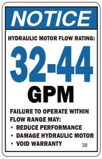
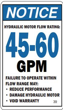
Hydraulic Flow Requirements
When operating the disc mulcher set the machine engine RPM to a speed that will produce the required flow. Your machine dealer can measure the flow available on your machine and recommend a throttle setting that is compatible with this attachment.
3.5 DISC Safety

Observe ALL safety precautions outlined in this manual.
NEVER operate a Disc Mulcher with the disc trajectory in the plane of the carrier or other persons.
NEVER WELD ON A DISC.
Replace the disc if cracks and or excessive damage are detected.
Before attempting to begin mulching operation,ensure that all personnel or bystanders are standing on the other side of the disc rotation and are at least 300 feet away.
1. ALWAYS inspect disc assembly every shift BEFORE start-up.
2. The disc should be inspected throughout the day, and immediately after contact with rocks or other foreign material to minimize the risk of parts injuring someone.
3. NEVER operate the mulching disc system partially assembled, in an unbalanced condition, or with any parts missing.
4. SERIOUS bodily injury may result from spinning an improperly, or incompletely assembled disc. All teeth MUST be properly fastened in place.
5. Mulcher disc rotates up to 1050 RPM. Never exceed the RPM limits of a disc, serious damage, bodily injury or death may occur.
6. NEVER WORK ON THE DISC MULCHER WHILE THE DISC IS RUNNING!
The disc weight is near 1000 lbs. ALWAYS use suitable lifting equipment when handling a mulcher disc.
ALWAYS keep in mind that the mulching disc at operational speed carries a tremendous amount of stored energy.
Tooth top speed can be up to 200 mph. Flying chips, debris, rocks, gravel, chunks of wood, etc., any tools or parts left on the disc during inspection or maintenance, can cause serious injury or death.
The operator should always remain in the cab while the disc is operating and should ALWAYS STOP THE DISC BEFORE APPROACHING.

Please refer to our “Hydraulic Fluid and Oil Statement” on Page 5 for gear oil or hydraulic fluid instructions.

Before operating disc mulcher, check the hydraulic fluid level in the host machine and add fluid if necessary.
Make sure the case drain hose is properly attached to the host machine’s case drain connection.
Warranty WILL BE be void if attachment is ran without the case drain hose connected. Excessive hydraulic pressure can blow out seals and damage the motor.
Verify that hydraulic hoses are securely locked to the machine hydraulic couplers before starting the mulcher.
1. Before starting the mulcher, visually inspect the disc mulcher and make sure all mulcher disc mounting bolts are property torqued and none are missing.
2. Verify the disc mulcher is properly attached to the host machine and all locks are in place.
3. Verify the hydraulic hoses and connectors are properly attached with no hoses pinched.
4. The operator should enter the operator’s cab, shut the door, and remove the “DO NOT START ENGINE” sign.
5. After starting machine, lift the attachment 12 inches off the ground.
6. Set machine engine RPM to just above idle.
7. Switch on the auxiliary hydraulic circuit.
8. Allow the disc mulcher to run for 30 seconds to purge air from the system, then switch off the auxiliary hydraulic circuit and allow disc to come to a complete stop
9. Lower the disc mulcher to the ground, set the parking brake, shut off machine engine and exit the cab.
10. Check the hydraulic fluid level in the machine, add manufacturer recommended fluid if necessary.
11. Inspect the disc mulcher hydraulic lines for noticeable leaks. Fix before continuing.
12. The operator should re-enter the operator’s cab and shut the door.
13. Restart machine, set engine RPM to slightly above idle.
14. Raise disc mulcher off the ground and switch on the auxiliary hydraulic circuit.
15. Once the disc mulcher ramps up to speed, increase machine engine to full throttle for use.
To avoid serious injury by hydraulic fluid injection into your skin, never use your hand or other body parts to locate a hydraulic leak. Detect leaks with a piece of wood or cardboard. Flesh injected with Hydraulic fluid may develop gangrene or other permanent disabilities.
3.7 Mulching Operations
General Operating Tips
1. LEARN what the disc mulcher looks like in a level position when you are seated in the machine. Knowing what a level mulcher looks like will prevent you from damaging the disc if you cut too close to the ground.
2. SLOW down the machine if the engine “bogs” down or if the disc speed is too slow because of too much load.
3. If you feel a strong vibration or shaking while mulching,IMMEDIATELY shut the attachment and machine down, Wait until the disc stops rotating completely and investigate the cause. An unbalanced condition suggests serious problems such as loose bolts, missing parts, etc., and should not be taken lightly. Refer to the “Troubleshooting Chart” on page 33.
4. Keep mulcher away from excavator tracks, skid steers, wheels, or other machinery. Used improperly, this disc can and will cut or damage any object in its path.
5. ALWAYS be aware of your surroundings and pay attention to obstacles and terrain around you.
6. Keep windows and Polycarbonate doors securely closed while operating attachment.
7. Keep all guards and shields in place.
8. NEVER try to cut or mulch any material other than wood and plants.
DO NOT use on or near electrical power lines, telephone poles, or fences. Electrocution can occur even without actual contact with an electric power source.
3.8 How to Start DISC MULCHER
Starting the Mulcher

To avoid serious injury or death from thrown objects and flying debris, ensure no bystanders are within 300 feet of the work area before starting this disc mulcher.
To avoid unexpected starting of the machine engine which could cause injury or death to the maintenance personnel working on the disc, proceed to lockout and de-energization of the machine. Attach a warning tag such as “DO NOT START THE ENGINE” to the controls indicating the nature of the current maintenance.
Walk around Inspection Daily /
10 Hrs
BEFORE STARTING MULCHER:
All mulcher disc mounting bolts are properly torqued and none missing.
Disc is in good condition. No cracks, gouges, or heat discoloration.
All tooth holders are sitting flat with disc.
All teeth are still sharp and are not worn round at corners. X
START UP:
All protective devices are in place and secure.
Warning sign “Stay out of Reach” in place & visible.
No unusual noises or vibrations.
1. Before starting the mulcher, visually inspect the disc mulcher and make sure all mulcher disc mounting bolts are property torqued and none are missing.
2. Verify the disc mulcher is properly attached to the host machine and all locks are in place.
3. Verify the hydraulic hoses and connectors are properly attached with no hoses pinched.
4. The operator should enter the operator’s cab, shut the door, and remove the “DO NOT START ENGINE” sign.
5. After starting machine, lift the attachment 12 inches off the ground.
6. Proceed to the area cordoned off for work.
7. Switch on the Auxiliary hydraulic system and increase the machine’s RPM to the appropriate level for mulching.
Drive Forward To Debris Pile...

1) Keep push bar against the tree while cutting.
Use the push bar to push the tree while cutting to prevent it falling back on the host machine..
Lower the disc mulcher onto the pile of debris and drive forward. Continue to mulch as you reverse. 2 1 3
2) As the tree falls, tilt the front of the mulcher up which will pull in the trees and branches as they fall.
3) Continue to slowly lower the disc mulcher onto the stump to mulch.
Keep the operator’s door tightly closed to prevent injuries or death caused from flying debris.
Repeat Until Satisfied With Mulch Size...

Use Caution as the tree may kick back towards the host machine while falling!
3.10 How to Stop Disc Mulcher
Stopping the Disc Mulcher

After switching off the auxiliary hydraulic circuit, keep hands and feet clear of the disc mulcher until disc rotation has come to a complete stop.
If disc mulcher vibrates while increasing RPM’s, switch off the auxiliary hydraulic circuit, wait until the disc stops rotating, turn off the motor, set parking brake and investigate the cause. Refer to the Troubleshooting Chart on page 33.
1. Raise the cutter slightly and set machine engine RPM to idle.
2. Switch off the auxiliary hydraulic circuit.
3. Allow the disc mulcher to slow down and come to a complete stop.
4. Lower attachment to the ground, set parking brake, turn off the machine motor, replace the sign warning “DO NOT START THE ENGINE” and carefully exit the operator’s cab.
SECTION 4
MAINTENANCE PROCEDURES
The maintenance procedures described in this manual should only be carried out by qualified mechanics who have been trained to repair this attachment. Some procedures require special tools and skills to complete. DO NOT attempt to repair or perform service work on this attachment unless you have the skills and tools to do so. Contact your local dealer for maintenance and repair services.
Welding Repairs-NEVER Weld on a disc
Welding on attachments must be performed by certified welders who have requested and obtained written approval from an authorized representative of the manufacturer before welding begins. All authorized welding repairs must be performed by qualified welders in accordance to the American Welding Society (AWS) standards. Welding procedures performed by unqualified welders may deem this mulcher unsafe to operate and VOID THE WARRANTY!.
Parts
Only use genuine KIOTI OEM replacement parts on this attachment. KIOTI will not be liable for any damages or injuries caused by the use of after market parts on this attachment.

Improper maintenance or modifications to the design or performance of this attachment will void the warranty.
Obey the following safety instructions when servicing or repairing this attachment
Wear proper Personal Protective Equipment (PPE) while working on this attachment, which may include safety glasses, hard hats, steel toe boots, gloves, etc.
Wear a welding helmet when welding to protect your eyes, face and neck from flash burn, ultra-violet radiation and heat.
Ensure all jack stands, lifts and hoists are in good working condition and have the rated load capacity to support the load.
4.0 Maintenance Overview Cont.
Only perform service work in a well-lit area.
Allow the attachment to cool down before servicing this attachment. Hot oils can burn your skin.
NEVER work under an unsupported disc mulcher.
4.1 Maintenance Schedule
This disc mulcher attachment will provide years of dependable service if routine maintenance procedures are performed. The maintenance tasks listed below are based on normal operating conditions. More frequent maintenance may be necessary with intense use or when operating in adverse environmental conditions.
Check host machine’s hydraulic fluid level. Add manufacturer recommended fluid as necessary. Please refer to our “Hydraulic Fluid and Oil Statement” on Page 5 for gear oil or hydraulic fluid instructions.
Check that all fasteners (nuts, bolts, washers, pins, keepers) are in place. Tighten as necessary.
Inspect and replace any worn, torn, or missing safety decals.
Inspect hydraulic hoses and connectors for damage or leakage. Repair or replace hydraulic items as necessary.
Change Shell Omala S2 GX 150 oil in bearing house.
*Change oil after 50 hours of first time use, then every 1000 hours or yearly.
Wash disc mulcher
Check disc mulcher for major scratches & dings. Sand and repaint these areas to prevent rust damage. *Contact the manufacturer for approved OEM paint for your attachment.
BEFORE STARTING MULCHER:
All mulcher disc mounting bolts are properly torqued and none missing.
Disc is in good condition. No cracks, gouges, or heat discoloration.
All tooth holders are sitting flat with disc.
All teeth are still sharp and are not worn round at corners.
START UP:
All protective devices are in place and secure.
Warning sign “Stay out of Reach” in place & visible.
No unusual noises or vibrations.
SHUT DOWN:
When mulcher disc binding or pinching
When mulcher disc jammed.
Check Fastener Tightening Torques. Instructions on Pg 41.
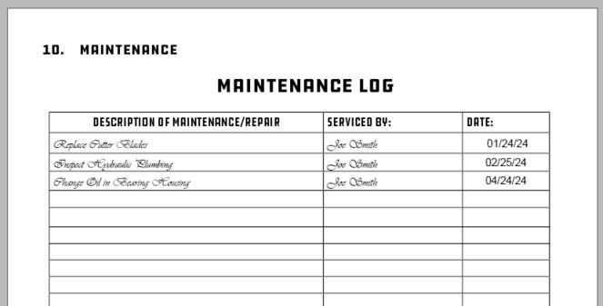
4.2 Maintenance Log Instructions
Document all maintenance and service activities performed on this brush cutter using the maintenance log sheets included at the end of this manual.

MAINTENANCE LOG
4.3 Storage Tips
To get years of quality use out of your brush cutter, follow these tips when storing your brush cutter for the season:

Ensure mulcher is free of debris, dirt and grease.
Store your mulcher in a dry shed or garage.


When storing your mulcher for the season, cover with a weather proof tarp to protect it from the elements.
4.4 Torque Specification Table and Instructions
TORQUE VALUES
Bolt torque INSTRUCTIONS
1. Apply and maintain proper torque on all bolts.
2. Torque values are based on lubricated values. Do not grease or oil bolts.
3. Wipe bolts clean and use Loctite 635 or equivalent before tightening bolts. May need curing activator.
4. Use a torque wrench to assure the proper amount of torque is being applied to the bolt.
5. MUST CURE 72 HOURS BEFORE USE TO PREVENT LOOSENING OF BOLTS.

4.5 Torque Equipment Requirements
TOOLS & EQUIPMENT REQUIREMENTS
To complete the maintenance procedures described in this section, you may need the following tools:
• 1/2 inch drive breaker bar
• 3/4 inch impact socket
• 1/2 inch impact socket
• Tapping Hammer
• 1/2 inch drive torque wrench
• Nylon pry bar set
• Safety stands

• Loctite 635 or Equivalent-MUST CURE 72 HRS
• Lifting device (overhead crane hoist, forklift)
When removing bolts with Loctite, it will be necessary to apply localized heat of at least 250 degrees Celsius or to 482 degrees Fahrenheit to loosen bolts.
LOCTITE 635 technical specifications for bonding, curing, removal and installation can be found here: https://next.henkel-adhesives.com/
1. NEVER weld on a disc.
2. REPLACE the disc if cracks and/or excessive damage are present.
3. The disc MUST be disassembled at every 2,000 service hours (hour meter only) allowing for complete inspection which is impossible on an assembled unit.
4. For repairing and rebalancing of the disc, it is strongly recommended to utilize the assistance of a local authorized service center.
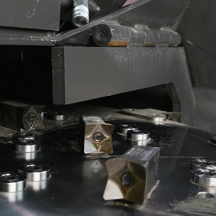

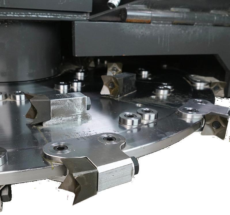
4.7 Tooth holder inspection
Tooth Holder Inspection
1. Mulching disc is firmly on the ground in the vertical position. Proceed to the lockout procedure of the carrier.
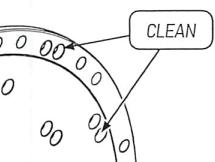
2. While slowly rotating the disc by hand, thoroughly clean the visible part of DISC, all TOOTH HOLDERS, and TOOTH.
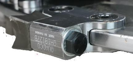
3. Carefully inspect each TOOTH HOLDER for cracks, damage, or excessive wear, looseness, missing or damaged SLEEVE, and SLEEVE BOLT.
4. All damaged or loose parts MUST BE REPLACED.
5. Replace ALL damaged and/or excessively worn TOOTH HOLDERS. Refer to “Tooth holder maximum wear limit” on page 29.
6. Refer to the Disc part nomenclature on page 41 & torque specification chart on page 41 for tightening torque values and conditions.
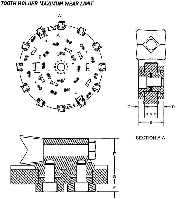
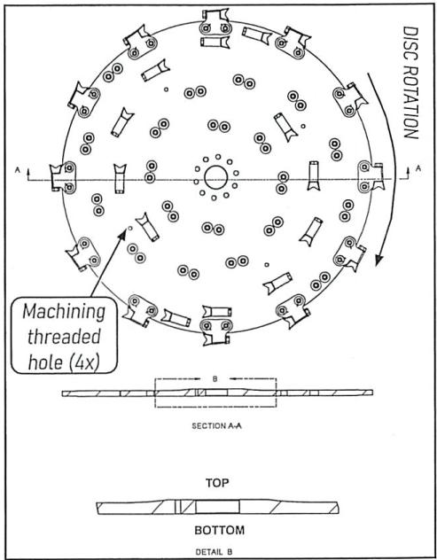
G- Disc general thickness
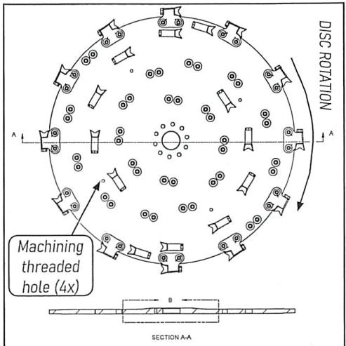
Pay attention to the disc rotation. Tooth holder spiral direction can easily be mounted in the wrong direction. To assure good rotation direction, locate the top of the disc by locating the hump on the top side.
mm (1.00”) See inspection procedure
4.9 Teeth INSPECTION
Teeth Inspection
1. Mulching head is firmly on the ground in the vertical position. Proceed to the lockout procedure of the carrier..
2. With gloves, slowly rotate the disc by hand, Thoroughly clean the visible part of DISC, all TOOTH HOLDERS, and TOOTH.
3. Carefully inspect each TOOTH, TOOTH BOLT, and FLAT WASHER for looseness, cracks, damage, or excessive wear.
4. All damaged or loose parts must be replaced. Refer to “Disc part nomenclature & torque specification” on page 41 for tightening torque value and tightening condition.
5. Carefully inspect ALL teeth. Teeth should have should sharp cutting edges for maximum productivity. Refer to Tooth maximum wear limit” below.
6. Loosen TOOTH BOLT and tap on the head of the bolt until TOOTH pops loose. Heat may be needed. Refer to page 27 for instructions.
7. Remove TOOTH BOLT, FLAT WASHER, and
TOOTH. Note: Use FLAT WASHER on peripheral tooth only.
8. Ensure that the mating surfaces of the TOOTH and TOOTH HOLDER are clean and free of burrs.
9. While holding TOOTH snugly against TOOTH HOLDER, install FLAT WASHER (on PERIPHERAL TOOTH HOLDER only), then screw in and torque TOOTH BOLT to specific tightening torque values and tightening condition as specified in “Disc part nomenclature & torque specification” on page 41.
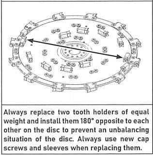
10. Repeat this procedure for the opposite tooth and for all other teeth that have to be replaced.
11. ALWAYS replace two teeth of equal weight and install them 180˚ opposite each other to prevent the disc unbalancing. Always use new bolts and washers when replacing them.
Check for tooth assembly clearance. The shoulder of the tooth must fit snugly against the shoulder of the tooth holder.
Damaged or worn teeth will reduce disc life and decrease operating efficiency. ALWAYS use sharp teeth.
Replace teeth undeR the following conditions:
• Unbalanced disc
• Missing tooth
• Damaged Teeth (fragmented)
• Worn cutting edges.
Worn teeth can be rotated to extend life. It is also good usage to make a rotation of surface and peripheral teeth as they don’t wear the same way. When making rotation from surface to peripheral teeth, try to match tooth weight to prevent disc becoming unbalanced.
Signs of tooth wear that affect Quality & Performance:
• Cutting and mulching speed abnormally slowing down.
• Excessive smoke.
• Cloud of fine sawdust.
• Excessive temperature of teeth.
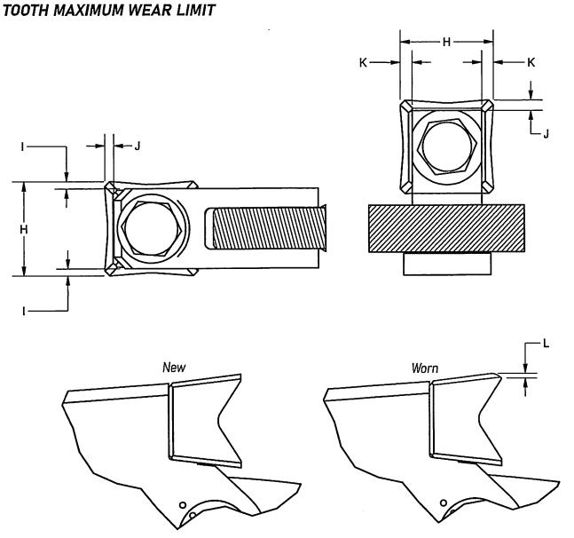
Tooth tip to holder top face TOOTH HOLDER (4)
K- Tooth tip to holder face (SURFACE TOOTH HOLDER (4B))

During the first 50 hours of operation of a new disc, the tightening torque of all fasteners must be checked & re-tightened if necessary, every day. Afterward, check according to the recommended intervals.

Tooth Manufacturer Recommended Tightening Torques: Tooth Bolt: Dry- 200 lb.-ft.
Sleeve
J-
How To Check Fastener Tightening Torques-Complete Weekly
1. With mulching head firmly on the ground, proceed to lockout procedure of the carrier.
2. Set the torque wrench 10% lower than the recommended torque value of the fastener to be checked.
3. Place the torque wrench on the head of the nut or bolt and pull the torque wrench arm steady until you hear the “click” of the torque wrench setting point.
4. If the nut or bolt does not turn, the torque is still good.
5. If the nut or bolt turns, replace it if necessary and tighten to the recommended torque value specified on “Disc part nomenclature & torque specification” on page 41.
6. Check torque of every accessible fastener, then move the mulcher 90˚ so the bottom of the disc is accessible.
7. Apply the lockout procedure.
8. Check the remaining fastener tightening torque.
Tooth Manufacturer Recom-
mends: If more than 3 broken bolts are found on a specific assembly, replace them all. A fastener should not be torqued more than twice. If so, the fastener should be replaced.
1. The disc MUST BE disassembled every 2,000 service hours (hour meter only) or earlier if the disc comes in contact with rocks or other objects.
2. Whenever a disc is disassembled for inspection, thoroughly check each part for irregularities as work progresses , allowing complete inspection of the disc which is impossible on an assembled unit. A damaged disc is unsafe and dangerous!
How To Perform Disc Complete Inspection-Every 2,000 hours
1. Make sure the mulching disc is securely on the ground in an optimal position.
2. Proceed to the lockout & de-energization procedure of the carrier and apply warning tag.
3. Remove all teeth from the disc.
4. Using adequate lifting equipment, remove the disc from the mulcher head and install it on a free rotating arbor mounted on bearings.
5. Thoroughly clean the disc and all its components.
6. Remove all holders as described in “Tooth Holder Replacement” on page 33.
7. Inspect the assembly, especially the cen-
ter of the disc and outer perimeter, for cracks, damage, and excessive wear, looseness, and for missing or damaged SLEEVE & SLEEVE BOLT.
8. Inspect each holder hole in the disc for roundness and cracks.
9. Inspect the interior of the TOOTH HOLDER for roundness and cracks.
10. Once the disc has been completely inspected and approved, it can be reassembled according to “Disc Assembly” on page 33.
11. Damaged discs MUST BE REPLACED and should NEVER be returned to service.
When the disc is attached to the mulcher, proceed to lockout and de-energization of the carrier to prevent unexpected starting of the carrier engine and attach a warning tag to the controls such as “DO NOT START THIS ENGINE”.
4.12 Replacing Tooth Holders
How To Replace Tooth Holders
All teeth should be removed from disc before removing disc from mulcher.
1. Using adequate lifting equipment, remove the disc from the mulcher head and install it on a free rotating arbor mounted on bearings.
2. With the TOOTH HOLDER to be replaced at 3 o’clock, lock the disc in place with a straight rod.
3. Heat the SLEEVE BOLT from the holder to be replaced to 480˚ F.
4. Using a breaker bar, loosen both SLEEVE BOLTs.
5. With a hammer, tap on the SLEEVE BOLT until the SURFACE TOOTH HOLDER or PERIPHERAL LOWER SLEEVE break free.
6. Always replace teeth in pairs to prevent an unbalance of the disc.
Overheating the disc and its components will cause irreversible damage to material and will greatly reduce disc assembly working life.
How To Assemble the Mulching Disc
1. Using adequate lifting equipment, remove the disc from the mulcher head and install it on a free rotating arbor mounted on bearings.
2. When replacing a TOOTH HOLDER or when re-assembling a used DISC, each tooth holder hole must be cleaned and any residual retaining compound removed. A wire brush can be used to remove the dry compound.
3. Using fast drying parts cleaner (ex:Loctite 30548) wipe out any residual dust and oil from every empty tooth holder hole. Also, thoroughly clean all TOOTH HOLDER, SLEEVE, and SLEEVE BOLT.
4. Starting with PERIPHERAL TOOTH HOLDER mounting holes, apply a retaining compound such as Permabond A134, Loctite 635, or equivalent into each PERIPHERAL TOOTH HOLDER corresponding disc hole. Spread the compound inside the hole with a small brush.
5. Then equally spread the bond all around the internal area of the hole with your finger.
6. Lock the disc in place using a straight rod going through one of the 4 matching threaded holes.
7. Install the PERIPHERAL TOOTH HOLDER on the circumference of the disc. Make sure to install the holder with teeth surface respecting the disc rotation.
8. Install both PERIPHERAL UPPER SLEEVE matching the positional holes on the sleeve and on the holder.
9. Repeat this procedure for each PERIPHERAL TOOTH HOLDER, then, unlock the DISC.
On lock rod removal of a partial assembled disc, the weight will carry the disc back and forth.
DO NOT TRY TO STOP THE DISC. Wait for it to stop on its own.
How To Assemble the Mulching Disc Cont.
Place the empty half on top, then complete the second half.
10. Once all holders are in place, from the bottom of the DISC, matching positional holes as per previous step, install each PERIPHERAL LOWER SLEEVE.
11. Apply a high-strength thread locker such as Loctite 635 on the threads of each PERIPHERAL LOWER SLEEVE.
12. From the top of the DISC, initially tighten all the SOC. HEAD BOLT 9/16-18 X 1”. Hand tighten for first few threads, then use an air impact gun set lower than the cap screws recommended tightening torque.
13. Finally, torque all the SOC. HEAD BOLT 9/16-18 X 1” according to “Disc part nomenclature & torque specification” on page 41.
14. Once all PERIPHERAL TOOTH HOLDERs are properly assembled in place and torqued, ensure that all sleeves do not protrude above either surface of the PERIPHERAL TOOTH HOLDER.
15. Lock the DISC again using the straight rod.
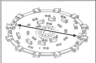
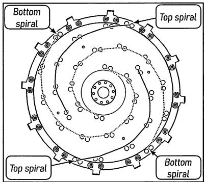
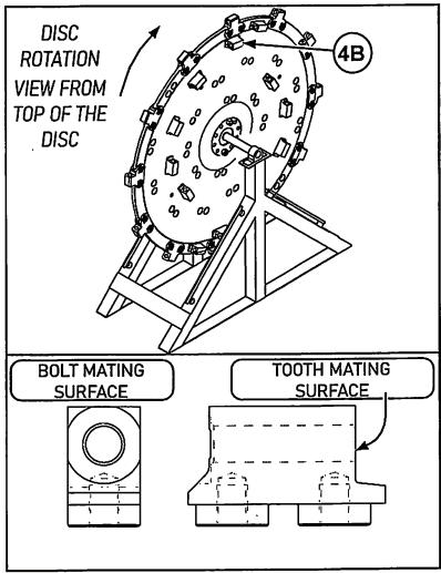
16. Before beginning of installing SURFACE TOOTH HOLDER, it is important to identify the tooth spirals. The bottom tooth spirals start closer to the center. Trace the spirals with a marker to identify the top & bottom spiral.
17. Apply a retaining compound such as
Permabond A134, Loctite 635 or equivalent in each SURFACE TOOTH HOLDER corre-
sponding holes of the top spiral.
18. Install the 12 top SURFACE TOOTH HOLDER on the disc, with tooth mating surface toward disc rotation direction.(4B)
19. From the bottom of the DISC, install all SURFACE SHORT SLEEVE and SURFACE LONG SLEEVE of the top spirals. NOTE: Use SURFACE SHORT SLEEVE on the two SURFACE TOOTH HOLDER located on the edge of the DISC.
20. From the bottom of the DISC, initially tighten all the SOC. HEAD BOLT 5/8-18 X 1 1/4” (8A) hand-tight for few first threads, then use an air impact gun set lower than the cap screws recommended tightening torque.
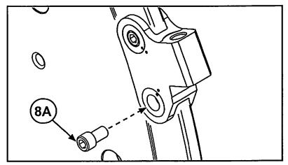
21. Finally torque all the SOC. HEAD BOLT 5/8-18 x 1 1/4” according to “Disc part nomenclature & torque specification” on page 41.
22. Repeat steps 16-22 from the bottom of the disc, for bottom spiral SURFACE TOOTH HOLDER installation.
How To Do A Partial Disc Inspection
1. Mulching head is firmly on the ground in the vertical position. Proceed to the lockout procedure of the carrier.
2. Thoroughly clean the visible segment of the disc and surroundings.
3. Slowly rotate the disc by hand to check for mechanical interference with the housing, such as rubbing, pinching, or jamming. Perform necessary repairs.
4. Also, while rotating the disc, perform a meticulous inspection of the disc conditions for cracks, gouges, heat discoloration, damage and excessive wear that can be seen from the top of the disc.
5. Now, with the disc function disabled, park the mulcher firmly on the ground at 90˚ to gain access to the bottom of the disc.
6. Stop the engine, turn off the master switch, and proceed to lockout of the carrier.
7. Thoroughly clean the bottom of the mulcher disc.
4.14 Disc Partial Inspection
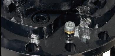
8. Check the BOLTING FLANGE (2) for loose, broken, or missing mounting cap screws.
9. Replace all loose, missing or defective mounting cap screws.
10. Thoroughly clean threads of a disc flange mounting holes. Torque as specified per mulcher.
11. If a bolt has been replaced, check the tightening torques of the remaining screws according to “How to Check Fastener Tightening Torques” on page 32.
12. From the bottom of the mulcher, perform a complete visual inspection of the disc conditions, for cracks, gouges, heat discoloration, damage, and excessive wear.
13. If cracks and/or excessive damage are present, replace the disc.
14. Damaged discs MUST BE REPLACED and should NEVER be returned to service.
It is strongly recommended that repairing or re-balancing of the disc is completed with a local authorized service center.
Please refer to our “Hydraulic Fluid and Oil Statement” on Page 5 for gear oil or hydraulic fluid instructions.

Your Disc Mulcher comes filled with oil from the manufacturer and DOES NOT NEED CHECKED UNTIL 50 HOURS.
Replacement motor/bearing housing, DOES NOT COME WITH THE OIL IN IT and MUST BE FILLED PRIOR TO USE!

Gearbox Oil Change Procedure (Optional for Routine and Required for Replacements)-Will Require Disassembly
1. Unbolt the Disc from the Gearbox/Motor. Support the disc with lifting equipment rated for the weight to prevent death from crushing. Move disc aside.
2. Take the Motor Cover off the mulcher.
3. Hydraulic Hoses may need removed.
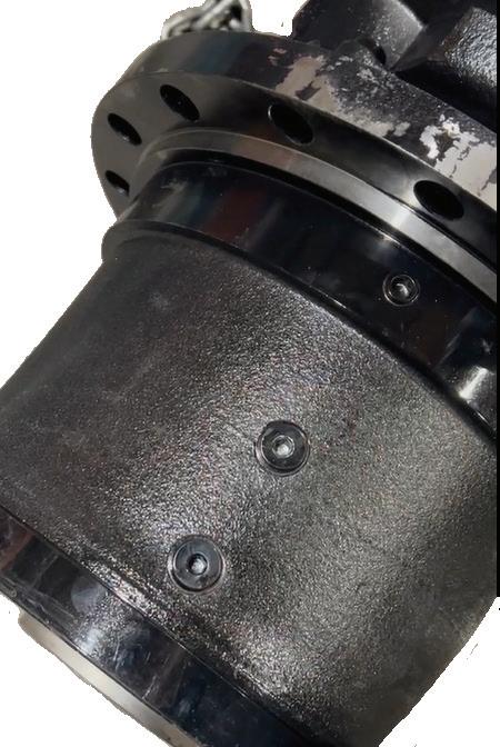
4. Unbolt the Motor and Bearing Housing from the deck of the mulcher.
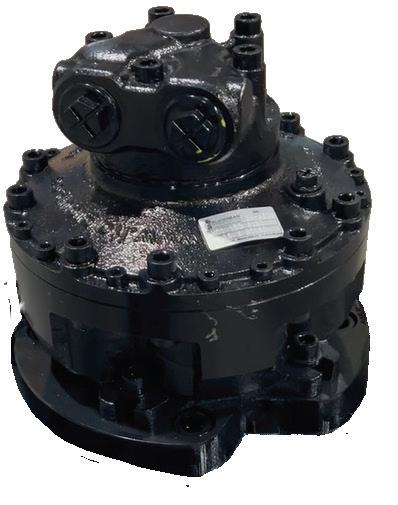
5. Attach a lift chain or strap to the Motor/ Gearbox for easier removal. See Example 1
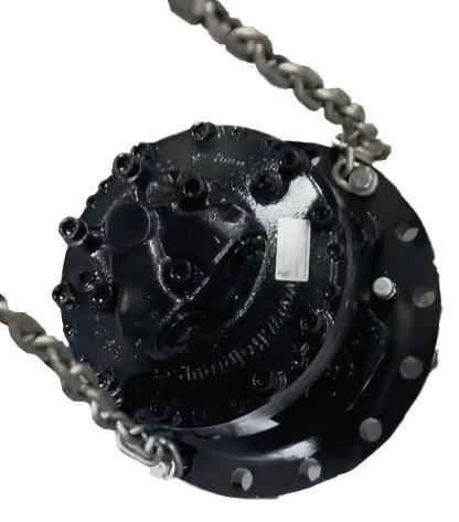
6. Remove Motor/Gearbox and set on a solid clean surface. See Example 2
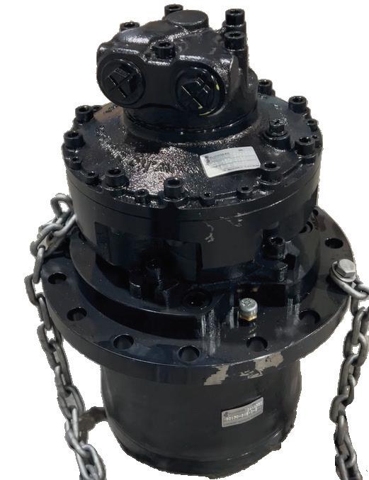
The disc weight is near 1000 lbs. ALWAYS use suitable lifting equipment when handling a mulcher disc. 1 2 4 3
7. Clean the outside of the Gearbox to prevent any contaminants from entering the oil ports and damaging the gearbox.
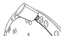
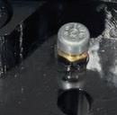
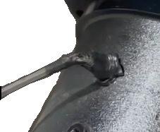
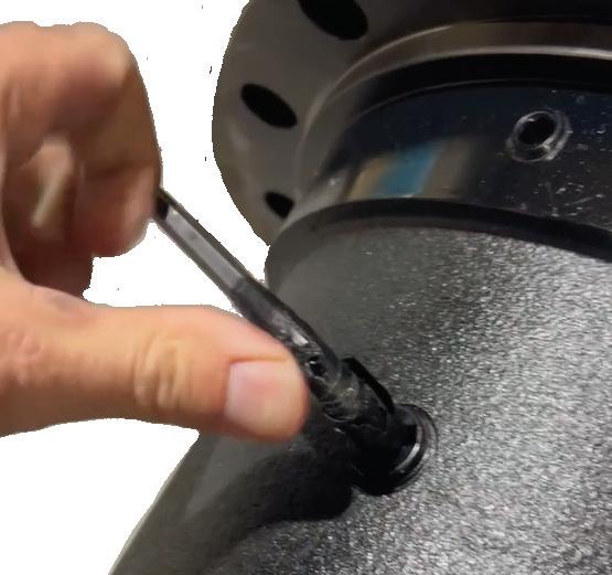
8. Use a wrench to loosen the air valve on top of the motor. See Example 3
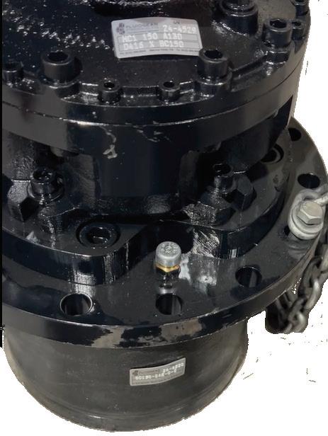
9. Lay the Gearbox on its side with the oil ports facing up. See Example 4
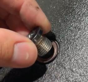
10. Remove both oil port bolts with an Allen wrench. Please note you may need a hammer or heat to loosen. See Example 5
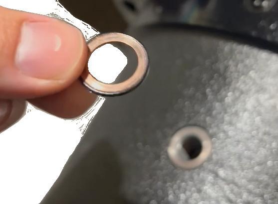
11. Remove the bolt and washer. Set aside. See Examples 6a & 6b

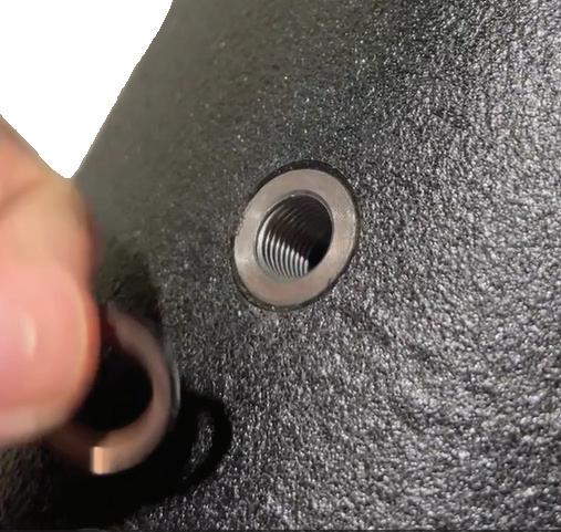
12. Stand the Gearbox up and allow the oil to drain from the port holes. (You may need to tilt the Gearbox to fully empty.)
13. Use a cloth to clean the oil from the outside of the Gearbox.
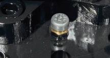
14. To Fill, use Shell Omala S2 GX 150 grade gear oil. Place your oil dispenser into the TOP PORT and fill until oil begins to run out the bottom port. See Example 7
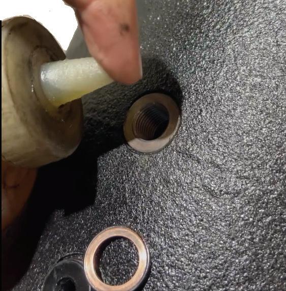

15. Place the washer and oil port bolt on the BOTTOM PORT and tighten tightly with an Allen wrench. See Example 8a & 8b
16. Continue to fill the oil port with Shell Omala S2 GX 150 grade gear oil, until the oil begins to run out of the TOP PORT.
17. Place the washer and oil port bolt on the TOP PORT as in Example 8
18. Tighten oil port bolt tightly with an Allen wrench. See Example 9
19. Tighten the air port on top of the motor. See Example 10
20. Place Motor/Gearbox back in position on the deck and bolt into place.
21. Reattach the hydraulic hoses.
5 7 6b 6a 8b 8a 9 10
22. Reattach the Motor Cover on the mulcher.
The initial oil should be changed after 50 hours of operation under load. Subsequent oil changes should take place after every 1000 hours of operation. More frequent oil changes may be necessary if operating this cutter in extreme hot conditions.
Gearbox Oil Change Procedure-While Partially Assembled
1. Position the mulcher deck in a level position on the ground to prevent the attachment from moving or falling and causing serious injury or death.
2. Remove the Motor Cover from the Deck.
3. Clean the motor and gearbox to prevent contaminants from entering the Gearbox during the oil change.
4. NOTE: The Gearbox is bolted to the deck and the motor is bolted to the Gearbox.
5. Unbolt only the Motor from the Gearbox. See Example 1
6. Use a wrench to loosen the air valve on top of the gearbox. See Example 2
7. Using a suction pump, empty out the oil in the gearbox.
8. Fill the gearbox with 2.5 quarts of Shell Omala S2 GX 150 grade gear oil.
9. Reattach the Motor to the Gearbox.
10. NOTE: Make sure the O-Ring is seated and not damaged. The O-Ring may need re-oiled to seal properly.
11. Tighten the air valve on top of the gearbox. See Example 2
12. Reattach the Motor Cover to the Deck.
NOTE the appearance of the oil. If it is very dark or has excessive metal shavings, a full oil change is recommended.

Troubleshooting SECTION 5
Problem
Mulcher bogs down or loses power.
Possible
Cause Solution
Foreign material is accumulating in the deck.
Bearing failure-(To diagnose, shut off hydraulic flow to cutter then slowly rotate the blade holder assembly & listen for bearing noise.)
Mulcher speed too slow or ground speed to fast.
Hydraulic fluid flow too slow.
Remove foreign material from inside the mulcher deck.
See dealer for bearing housing service; replace bearing housing.
Increase RPMs and reduce ground speed.
Look for hydraulic leaks & repair.
Replace damaged teeth.
Excessive Vibration
Teeth dull too quickly or are breaking too easily.
Hydraulic fluid level goes down during operation.
Disc does not rotate when flow is activated.
Missing, loose or damaged teeth. Disc damaged. Bearing failure.
Teeth are receiving excessive shock loads from contacting solid objects (rocks, steel pipes, etc.)
Hydraulic motor leak, or leaks in prime mover’s hydraulic system.
Hydraulic motor or bearing house failure.
Hydraulic lines disconnected.
Problem with machine hydraulic controls.
Replace blade holder.
Repair or replace bearing housing.
Clear the cutting area of solid objects, raise cutter height to clear exposed rock surfaces.
Investigate and repair leaks.
Contact dealer for repair service.
Connect hydraulic lines to machine couplers. Ensure hoses are locked in place.
Contact machine dealer for diagnosis and repair
ONLY service the mulcher on stable, even terrain. NEVER park on sloped terrain to avoid being struck and killed or seriously injured by the unexpected rolling or movement of the machine.

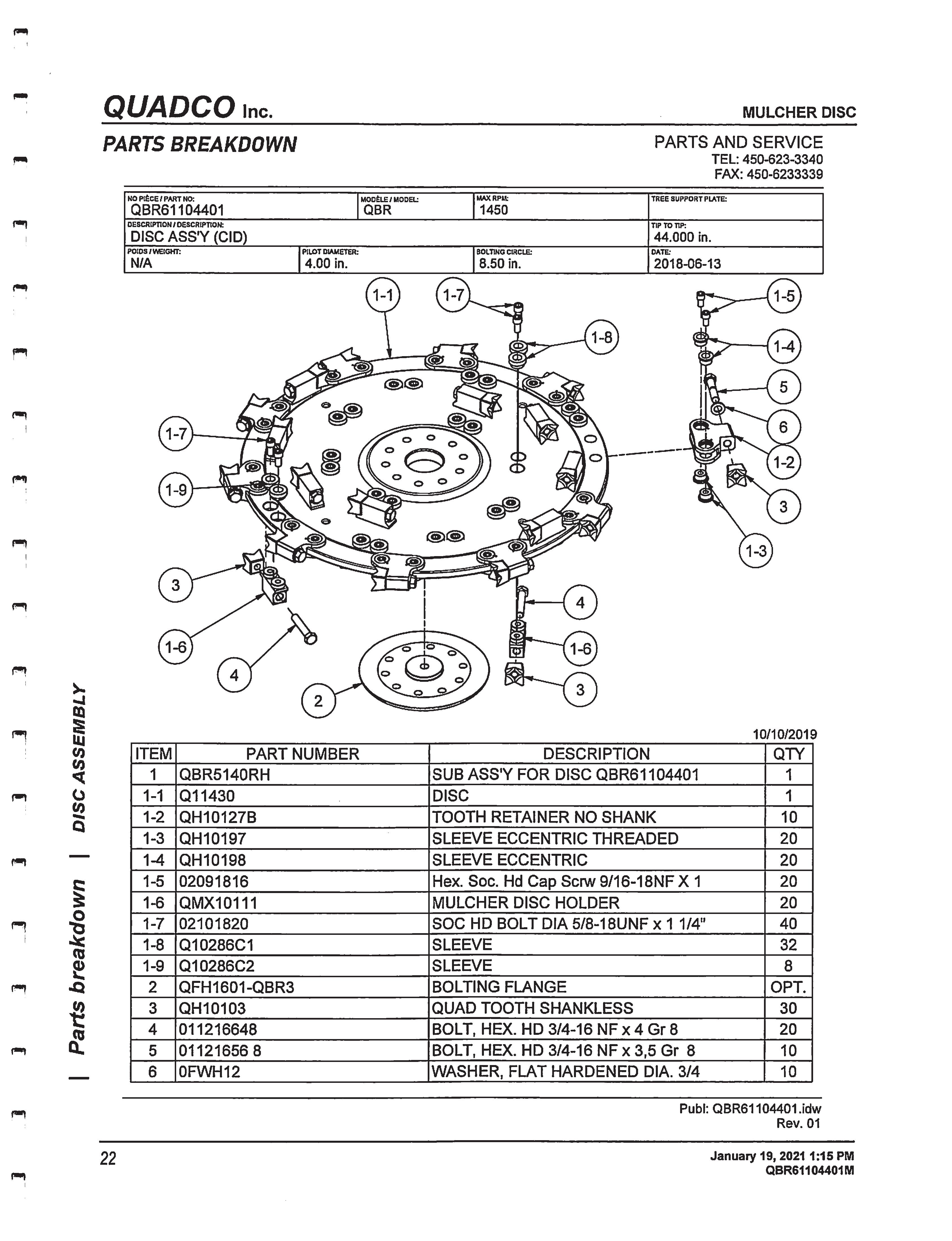
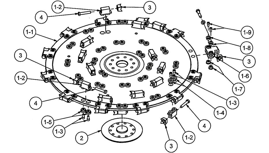
parts information SECTION 7
Factory fresh parts specifically designed for your implement are readily available.
For hassle free service and to ensure you receive the correct parts for your implement, please provide your dealer with the following information:
Model Number
Serial Number
GPM Requirements
Date of Owners Manual
(Bottom Left Corner of Cover Page)
Parts Diagram Page Number
Part Description
Reference #
Quantity Desired
Ship To Information
Bill To / Payment Information
7.1 44” Mulcher Disc Parts Diagram
Warranty Information SECTION 8
LIMITED WARRANTY
LACKENDER products are warranted to be free from defects in workmanship or materials for a period of 12 months from the initial sale.
Warranty Exclusions
This warranty does not cover normal wear items, including but not limited to: bearings, hoses, blade holders, ground engaging parts such as teeth, blades, cutting edges, pilot bits, auger teeth and broom bristles. This warranty does not cover maintenance, service or adjustments. This warranty does not cover damage due to improper application or installation, misuse, negligence, accidents or improper maintenance. Please note: Any modification or customization made to your attachment may void its warranty. This warranty is void if any components have been disassembled, i.e., pumps, gear boxes or motors or the attachment has been used without the case drain attached (if applicable). Be sure to follow all recommended Horsepower and GPM requirements as outlined in product specifications, in order to prevent the warranty from being void. This warranty is contingent upon the use of approved BRAND parts exclusively. Any use of non-approved parts may result in voiding the warranty. Please be advised that the warranty does not cover refurbished attachments. Specially modified attachments built by the manufacturer to meet your needs shall not be warranted by Lackender.
REPAIRS UNDER WARRANTY
Any repairs, including welding, on attachments must be performed by certified repair technicians who have requested and obtained written approval from an authorized representative of the manufacturer before repairs begin. If you are completing the repair, you must also have prior written approval to prevent the warranty from being voided.
Warranty Statement
Our obligation under this Limited Warranty shall be solely limited to repairing or replacing any part (see noncovered items above) that, according to our judgment, show evidence of a defect in quality of workmanship or materials for the stated 12 month warranty period. All defective parts must be routed directly to Lackender with freight or delivery charges to be prepaid. This limited warranty shall not be interpreted to render Lackender liable
Warranty Statement CONT.
for any injury or damage to persons, businesses or property of any kind nor expenses or losses incurred for labor, supplies, substitute machinery rental or for any other reason. Repair or replacement parts are subject to the supply conditions at the time of repair or replacements, which may directly affect our ability to obtain material and/or replacement parts. Lackender reserves the right to make improvements in design or changes in specifications at any time without incurring any obligations to owners of previously purchased products.
No one but Lackender is allowed to alter, modify or enlarge this warranty nor the exclusions, limitations and reservation at any time. Lackender products are warranted to be free from defects in workmanship or materials for a period of 12 months from the initial sale.
. Purchaser and Manufacturer hereby (a) submit to the non-exclusive jurisdiction of the courts of competent jurisdiction in the state and county in which this company resides for resolution of any dispute concerning this Limited Warranty or the rights or obligations of Purchaser and/or Manufacturer; (b) agree that any litigation in connection with this Limited Warranty shall be venued in the state and county in which the company resides and (c) waive any objection they may have as to any such action or proceeding brought in such court that such court is an inconvenient forum. Nothing herein shall limit the right of Purchaser or Manufacturer (or the right of any permitted successor or assign of either) to bring proceedings against the other in the courts of any other jurisdiction wherein any assets of such other party may be located.
This warranty and return policy is governed by the current policies posted on the manufacturer’s website.
8.1 warranty Return Authorization Policy
Warranty Return Authorization Policy:
If repairs are required, Lackender must obtain a Return Material Authorization (RMA) number from the manufacturer of the defective part and proof of purchase. RMA and services are rendered by Lackender only. Any responsibility of shipping costs on any item returned for repair is at the discretion of Lackender.
All returned parts must have the following:
1. A legible RMA number written on the outside of the package.
2. Warranty Claim Form (online)
3. The defective part.
RMA numbers are only valid for 30 days from the date of issue. All shipped replacement parts may require a Parts Order (PO) number from the original Lackender dealer. Repairs not covered by the warranty, will be charged for parts and labor at the current pricing rate. Should you have any problems with your attachment, please follow the instructions listed on the following page.
8.2 warranty Procedure
Warranty return authorization procedure:
1. For Warranty Concerns please contact your local dealer. You will need to provide the model and serial number of the defective item(s), (See Appendix B: Where to find the model & serial number) a description of the problem, and have photographs available.
2. Upon a warranted issue, visit www.ecsattachments.com, click on the warranty tab, and fill in the warranty information on the Warranty Claim Form.. Lackender will retain a Return Material Authorization (RMA) number from the manufacturer of the defective part. If all the information above is completed the manufacturer will issue a RMA number via email..
3. Once you have an approved RMA number, a shipping label will be provided with the manufacturer’s address and instructions for returning the defective part. Appropriate RMA/ PO’s will be invoiced and payment received while the evaluation process is being completed to prevent delays in your normal business operations. In the event the defective part(s) is un-warranted and repairs are not covered by the warranty, the customer will be invoiced for any additional parts and labor at the current pricing rate. If the part is deemed under warranty, a credit of the invoice will be issued.
4. Lackender will ship a replacement part to the provided location or customer, with a RMA identifier of some kind. The customer is responsible for initial shipping charges until evaluation of the part has been completed. If the part failure is covered by the warranty, the customer will be reimbursed for any paid shipping charges. In the event, the part is not covered by the warranty, the customer is responsible for return shipping.
5. Once the defective part is warranted by the manufacturer, the customer will be issued a credit and the PO number will no longer be active.
6. In the event the manufacturer decides that the attachment needs to be returned to the manufacturer for repair, Lackender will make arrangements for pickup and return. Repairs will be performed by qualified technicians. Non-warranted issues will be discussed, and repairs will be performed upon the owner’s agreement and receipt of payment for parts and labor.
Safety Acknowledgment SECTION 9
ATTENTION ALL OPERATORS: Print your name, sign and date in the boxes below to acknowledge that you have read and fully understand the safety instructions presented in this manual, and have been trained on how to safely operate this attachment.
Operator Name
Signature Date
MAINTENANCE Logsheets
Use this log sheet to document all routine maintenance and repair services performed on this attachment.
Description of Maintenance/repair Serviced by: DAte:
The Model and Serial numbers will be in one of (4) places and will either be etched into the attachment or on a Data Plate.
Instructions: Stand at the back of the attachment facing the attachment mounting bracket and look in the following locations:
2) Top- left or right
3) Back-left or right
Model and Serial Number Data Plate
PLEASE NOTE: The Model and Serial number may be etched or on a Data Plate.
Disclaimer: Any critical changes made to this manual by individuals outside the manufacturer’s authorized personnel are doing so at their own risk. The manufacturer cannot be held legally responsible for any consequences, damages, or liabilities resulting from such modifications. It is advised to adhere strictly to the original manual provided by the manufacturer for optimal performance, safety, and reliability.