New Builds, Retrofits, and Flexible Speculative Facilities
RESEARCH + DEVELOPMENT
For enquiries please contact:
Scott Brownrigg Ian Pratt & Jason Lebidineuse
Hoare Lea Matt Jones
ARCHITECTURAL DESIGN GUIDE - APRIL 2025
Prepared for: UK Developers, Agents and Design Professionals
Introduction
Overall GMP Facility Design Considerations
Site Selection and External Design
Building Design and Construction Approaches
Building Services and Environmental Control
Internal Layout and Cleanroom Design
Cleanroom Materials and Finishes
Conclusion
INTRODUCTION
Good Manufacturing Practice (GMP) facilities are specialised environments designed to ensure the quality and safety of products in tightly regulated industries. These include pharmaceuticals and biotechnology (e.g. sterile drug production suites, cell/gene therapy labs), as well as advanced food processing, cosmetics manufacturing, and other life science sectors. In all cases, regulatory standards demand strict control over facility design, construction materials, and environmental conditions.
In the UK, the Medicines and Healthcare products Regulatory Agency (MHRA) enforces GMP requirements aligned with EU GMP guidelines (EudraLex Volume 4 and Annex 1 for sterile products) and global frameworks from the World Health Organization (WHO). International standards like ISO 14644 for cleanrooms also apply.
This means a GMP facility must be planned and built (or renovated) with meticulous attention to cleanliness, process flows, and environmental control from the outset. Key design considerations range from the highlevel site layout and building infrastructure down to the interior finishes and details. This guide provides developers and agents with a comprehensive overview of GMP facility design, covering new construction, retrofitting of existing buildings, and speculative “shell” developments, with practical guidance aligned to UK regulations (MHRA, EU GMP) and industry best practices.
OVERALL GMP FACILITY DESIGN CONSIDERATIONS
Designing a GMP-compliant facility requires integrating regulatory compliance, contamination control, and practical functionality into the building’s very concept. The goal is a fit-for-purpose facility that inherently supports product quality and meets or exceeds the required standards. Several broad principles drive the design:
Regulatory compliance and standards:
A GMP facility must satisfy all applicable regulations from day one. For medicinal manufacturing, regulators like MHRA and EMA (and FDA in the U.S.) specify that facilities be of suitable location, size, and construction to allow proper cleaning, maintenance, and operations
Cleanrooms are classified by air cleanliness (ISO 14644-1) and by GMP grade for sterile production (EU GMP Grades A/B/C/D). For example, Grade A critical areas correspond to ISO Class 5 (very low particle counts), while Grade C might correspond to ISO Class 7 at rest. These classifications dictate design targets such as maximum particle counts and air change rates.
Early collaboration with quality assurance and regulatory specialists is essential so that the layout and building systems align with validation expectations and “built-in” compliance. Regulatory bodies expect thorough documentation (e.g. design qualification) demonstrating that the facility can consistently operate under GMP conditions, and the finished building will undergo qualification to verify it meets those standards.
The facility design must also comply with local building regulations, for example, UK Building Regulations for fire safety and structural integrity alongside GMP requirements. There should be no conflict between building code compliance and GMP needs; any code-driven features (like fire exits or sprinkler piping) must be integrated in a way that maintains cleanroom integrity (e.g. using sealed, flush cleanroom-rated fire sprinkler heads).
Layout, zoning, and contamination control:
GMP facilities are laid out to segregate activities and prevent cross-contamination. This typically involves defined zones with controlled transitions (airlocks or vestibules) between them. Higher-grade clean areas (e.g. formulation or filling rooms in pharma) should be surrounded by support zones of the next lower grade to act as a buffer.
Grade A ~ critical ops
30-35 air changes per hour
max 100 particles per m3
Grade C ~ ordinary ops
10-15 air changes per hour
max 10,000 particles per m3
The flow of personnel and materials is ideally unidirectional or at least well-separated – for instance, raw materials enter through one route while finished products leave through another, never intersecting with waste streams. Airlocks are fundamental design elements at zone boundaries: these are small anterooms with two interlocked doors, allowing only one door to open at a time. In a typical GMP layout, there will be dedicated Personnel Airlocks (PALs) for gowning and entry of staff, and Material Airlocks (MALs) for equipment and supplies. Even changing rooms often function as airlocks to physically isolate the clean production space from less clean areas.
By carefully planning corridors, doorways, and airlocks, the building itself helps contain potential contamination and maintains required pressure differentials between areas. Clear demarcation of clean zones, support zones, and “grey” zones (less critical areas) is a core principle of GMP design.
The building layout should enforce proper sequencing: for example, personnel might flow from a general corridor → gowning room (airlock) → intermediate clean corridor → production room, with each step increasing their gown level and the room cleanliness. Likewise, material flow may progress from loading bay → quarantine storage → preparation → manufacturing, with clearly marked pathways and protocols. Waste flows must be segregated as well; often a separate exit path (or at least separate timing) is designated for waste removal so that waste does not travel back through clean areas.
Overall, the facility’s internal layout embodies the contamination control strategy, ensuring that people, products, and waste each move through the building in a controlled, nonintersecting manner.
Future flexibility in design:
Given the high cost of GMP facilities, owners and designers increasingly emphasise flexibility and future-proofing. A new-build offers the greatest freedom to optimise the design to meet current needs, but it should also accommodate future changes in process or increases in capacity. It is wise to slightly oversize critical utilities and service spaces (within reason) so that future equipment or rooms can be added without a complete overhaul. For example, installing a largercapacity air handling unit or extra pipework provisions during initial construction can save major upgrades later.
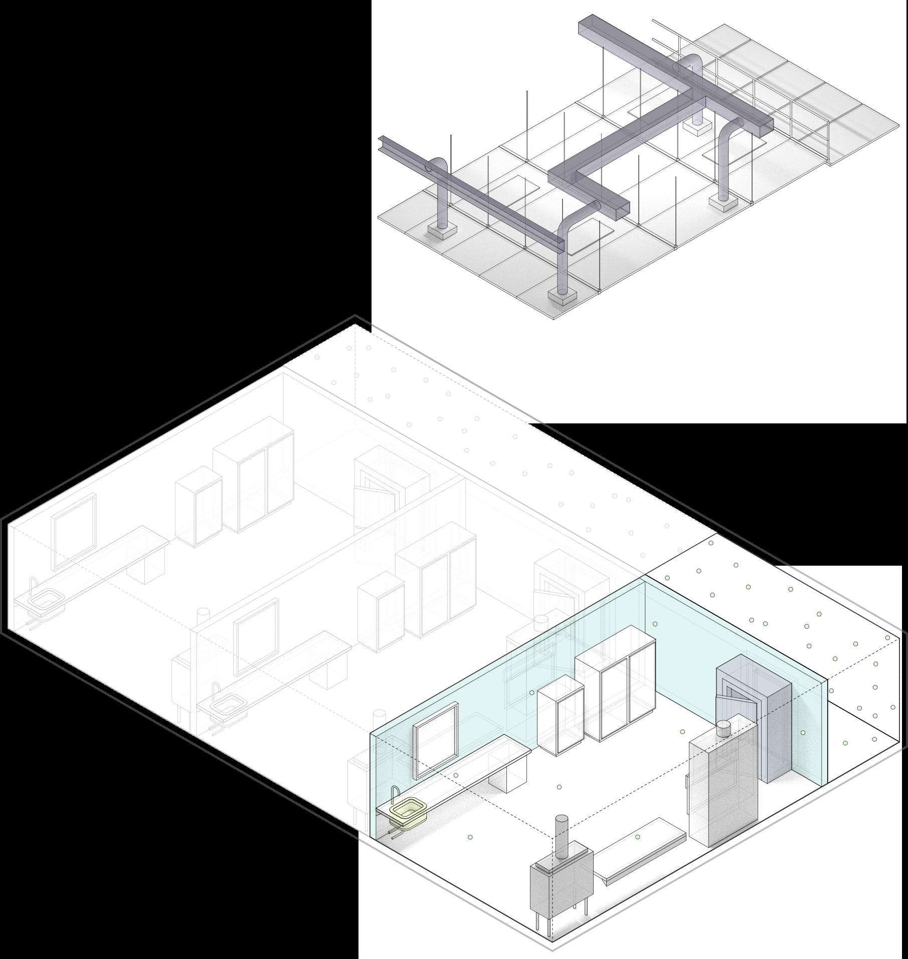
Many modern GMP facilities employ modular construction concepts to allow faster buildout and easier modification. This can range from using prefabricated cleanroom wall panels and ceiling systems (now common practice) to designing entire production suites as modular pods that can be inserted or reconfigured as needed. Modular cleanroom systems come with flush-sealing panels, coving, and integrated utilities, and they can
cleancorridor dirty corridor
Figure 2
3
be disassembled and moved if the layout needs to change.
Developers and designers should anticipate possible expansions; horizontally (additional wings or rooms) or vertically (adding mezzanines or floors), and reserve space on the site or within the building structure for this. For instance, a facility might be built with a “soft space” or shell area that can be fitted out later when production grows. The design might also include interstitial spaces (walk-on mechanical floors above cleanrooms) or accessible service voids to ease future installation of new pipes or air ducts.
By planning for adaptability from the start, the facility can accommodate new product lines or technologies with minimal disruption. This is especially important for multi-product or multi-use sites; the design should be robust enough (in materials, airflow, and utilities) to handle the “worst- case” product so that different products can be manufactured
sequentially with thorough cleaning in between.
In summary, quality by design in a GMP facility means not only meeting current requirements but also designing resilient infrastructure that can evolve with regulatory changes and operational needs. These overarching considerations set the stage for the more detailed decisions about location, building configuration, utilities, and interior fitout that follow. In practice, regulatory rules, operational workflows, engineering demands, and future goals should be balanced to create a cohesive facility design.
Figure
SITE SELECTION AND EXTERNAL DESIGN
The choice of site and the external layout of a GMP facility provide the first layer of control and support for compliant operations. At a macro scale, selecting a suitable location and designing the site plan properly can make it much easier to maintain GMP conditions inside the building:
Site location and planning:
An appropriate location is crucial. Industrial or science park locations are generally preferred, as they are already designated for manufacturing use and typically have the required infrastructure.
In the UK, planning permission is easier to obtain in areas already zoned or intended for industrial or laboratory facilities, including allowances for the use of chemicals or biological materials. Such areas are also less likely to pose issues with environmental pollutants that could affect a clean facility.
Ideally, the site should be in a clean, lowpollution environment. For instance, one would avoid situating a GMP plant downwind of a heavy smoke-emitting factory or adjacent
to sources of excessive dust, since that would increase the burden on air filtration systems.
Proximity to robust utilities is another practical factor: a site with existing ample electrical supply, water mains, and sewage capacity will reduce the need for extensive off-site utility upgrades.
While not a GMP requirement per se, being near supply chain hubs and skilled workforce pools is beneficial. For example, sites near major transport links (motorways, airports) can ease logistics for importing raw materials and exporting finished products. Access to local talent (engineers, technicians) is a consideration for facility operations.
Traffic flow and segregation:
While not a GMP requirement per se, being near supply chain hubs and skilled workforce pools is beneficial. For example, sites near major transport links (motorways, airports) can ease logistics for importing raw materials and exporting finished products. Access to local talent (engineers, technicians) is a consideration for facility operations.
trench drain
Figure 4
The site plan should separate shipping and receiving areas from personnel and visitor entrances to prevent unnecessary crossover. Typically, a GMP production site will haservice area should be isolated, often fenced with controlled gate access, to ensure only authorised transport vehicles enter.
It’s ideal to have the loading dock directly connected to a warehouse or material airlock within the building, minimising how far external goods travel through internal spaces. The site must also accommodate large lorries turning and parking; adequate loading berths should be provided based on the expected volume of traffic. If hazardous materials are delivered, a dedicated area with spill containment, such as a graded pad with a trench drain, may be required for safe offloading.
In contrast, the main entrance for employees and visitors should be on a different side of the building, leading to an administrative or lobby area. This entrance can be more welcoming in design but still requires security controls, such as badge access or reception sign-in procedures.
By segregating truck traffic from staff and visitor traffic, the site reduces the risk of accidental incursions, such as a visitor wandering near the loading zone or a delivery driver entering through a GMP personnel door. Clear signage, road markings, and possibly physical barriers (like fences or landscaping) should guide vehicles to the correct entry and prevent mix-ups.
Security and access control:
Many GMP products, especially pharmaceuticals, are high-value or sensitive, so strong site security is essential. This typically includes perimeter fencing, controlled entry gates, and comprehensive CCTV surveillance covering all approach routes. Some facilities may also require a security checkpoint or gatehouse at the entrance to conduct vehicle inspections before allowing access.
Site lighting should be adequate for nighttime monitoring, particularly around doors, pathways, and loading bays. Landscaping should be designed with visibility in mind, for example, using low shrubs instead of dense,
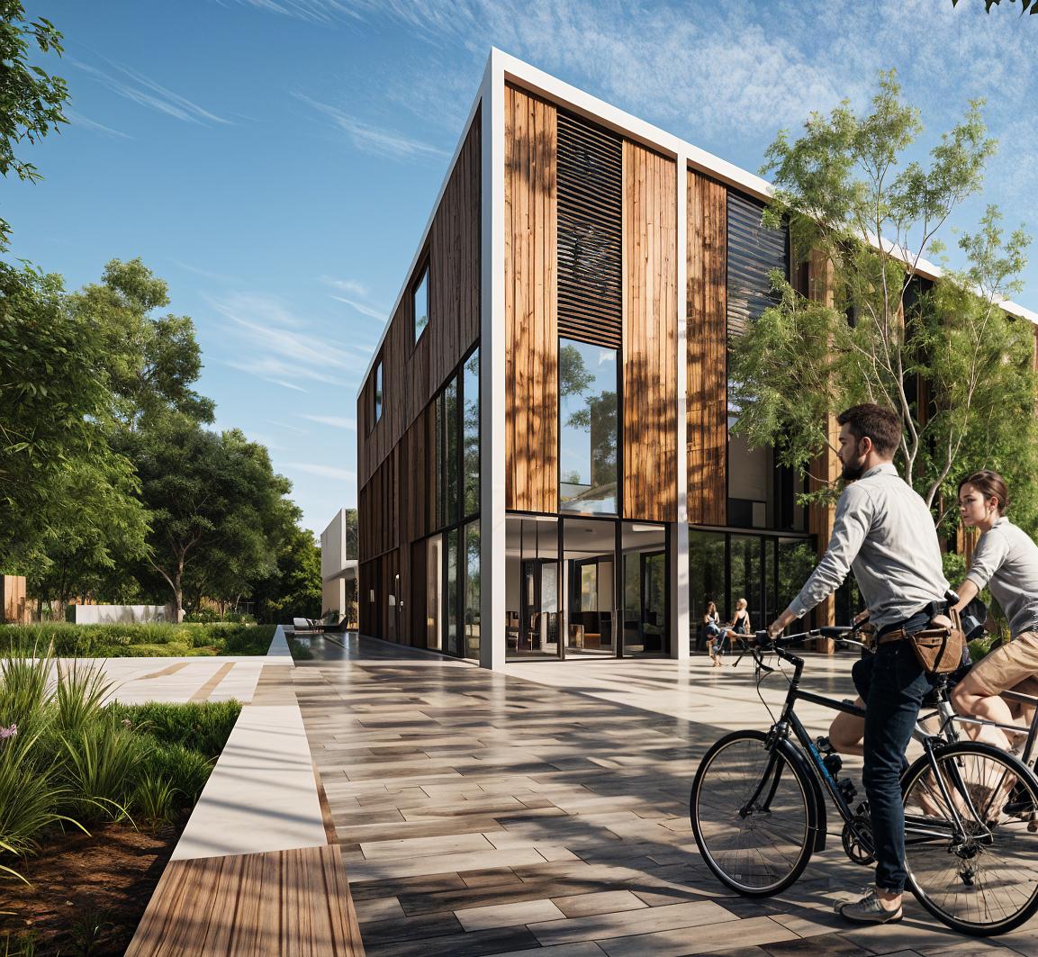
Learning Lab
(image generated by AI)
tall bushes adjacent to walls to eliminate potential hiding spots and support unobstructed camera views.
These security measures not only help deter theft or tampering but also prevent unauthorised access that could lead to contamination or breaches of GMP protocols. In a GMP context, controlling who and what enters the site is a critical part of maintaining a secure and compliant manufacturing environment.
External utilities and waste yard:
It is advisable to designate a specific services yard on the site for external equipment and waste handling. This fenced yard may house bulk utility systems such as backup generators (with associated fuel tanks), chillers or cooling towers, vacuum pumps, compressors, and waste disposal containers. For example, if the process requires it, liquid nitrogen tanks or gas cylinders can be positioned here, along with a diesel generator set and its bunded fuel tank. All equipment in this yard must comply with safety regulations, including separation distances from property lines and occupied buildings as specified by UK standards.
The yard also functions as the staging area for waste. This can include general refuse bins, clinical or biohazard waste containers, recycling skips, and hazardous waste drums, often kept in covered or weather-protected enclosures. To prevent risk of contamination, this area should be located away from building air intakes and clean zones, as waste materials may emit odours, particulates, or attract pests.
For biohazardous waste, some facilities employ refrigerated storage such as a chilled skip or container. If so, the yard must be equipped with a proper plinth and electrical connection for the unit. Additionally, the yard should allow easy access for service vehicles such as waste hauliers and fuel delivery trucks, ideally via a separate gate or designated service path.
Given the importance of the infrastructure and the potential hazards associated with materials in the yard, the area must be securely fenced and, where possible, actively monitored via CCTV or other surveillance methods.
Air intakes and exhaust placement:
The building’s exterior must be designed with careful thought to air intake and exhaust locations. Heating, Ventilation and Air Conditioning (HVAC) intake louvers that draw in fresh air should be high above ground level (often on the roof or high up on walls) and positioned well away from any contamination sources. They should not be near the loading dock, waste yard, or idling vehicles, to avoid drawing in exhaust fumes or dust.
Local wind patterns should be considered so that prevailing winds don’t carry smoke or kitchen/canteen exhaust into the intakes. Conversely, exhaust stacks, especially those releasing fumes, vapours, or biocontaminants, should be positioned and designed to vent safely. They may need sufficient height and velocity to ensure
discharged air is diluted and does not re-enter the building or affect neighbours.By carefully planning corridors, doorways, and airlocks, the building itself helps contain potential contamination and maintains required pressure differentials between areas. Clear demarcation of clean zones, support zones, and “grey” zones (less critical areas) is a core principle of GMP design.
Many jurisdictions (including UK standards) have guidelines for minimum separation distances between intakes and exhaust outlets (for instance, an intake might need to be at least 10 metres from any exhaust outlet or flue). The roof plan should allocate space for potentially large exhaust stacks (such as from biosafety cabinets, fume hoods, or boilers) and maintain the required clearances.
Figure
Coordination between the architect and mechanical engineer is needed early to reserve these external zones, as they impact roof design and possibly planning approval (tall stacks might require planning consent regarding visual/aesthetic impact).
Drainage and landscaping:
The site should be graded to ensure good drainage, directing rainwater away from the building. Water should not pool against the facility’s foundation, as standing water can seep in and become a source of contamination. Stagnant water encourages microbial growth and attracts insects.
Often, a concrete or gravel apron is installed around the building perimeter to keep vegetation back and allow maintenance access. This also helps prevent pests from nesting next to the building.
Landscaping can be used for aesthetics; many companies prefer an attractive campus, but it must be low-maintenance and chosen with GMP in mind. For example, one should avoid plants that attract insects or drop debris: fruitbearing trees or heavy pollen producers are not ideal near clean facilities. Lawns, rock beds, or sparse, well-maintained shrubs are better than dense foliage close to the building.
If decorative trees are planted, they should be located far enough away that falling leaves won’t clog drains or be drawn onto rooftop intake filters. Pest control measures should also be anticipated; outdoor bins should be sealed, and pest traps may be installed around the perimeter. Essentially, the exterior grounds should not become a harbourage for rodents or insects that could find their way inside.
Personnel amenities and access:
Although GMP facilities focus on controlled production areas, the site should also consider everyday employee amenities. Parking lots need to accommodate staff and visitor vehicles, with some capacity for future growth.
Walkways from parking to the building should be well-lit and possibly covered if the climate warrants it, both to keep people dry and to
Learning Lab
(image generated by AI)
reduce dirt being tracked indoors. If smoking is permitted on site, designated smoking shelters should be placed well away from building air intakes to prevent smoke infiltration.
Many facilities also use an entry vestibule or lobby as a place to implement basic contamination control. This might include sticky mats or airlock vestibules at the front door where shoe covers can be applied. While this area is outside the formal clean zone, it is good practice to reduce dirt and contaminants being brought in from outside.
Future expansion space:
When plotting the site, it’s wise to reserve some area for future expansion or additional utility installations. If there is a possibility of adding another wing or building in the future, ensure the current site plan leaves that area unencumbered by critical tanks, structures, or landscaping.
Also consider future equipment needs. For example, leave room for a second generator or a larger chiller plant if production doubles in the future. This might involve negotiating with utilities during the initial build to size certain incoming services for projected growth, such as installing a larger electrical feeder or extra ducts and conduits underground.
Environmental and regulatory external requirements:
External design must also comply with environmental regulations and permits. For instance, if the facility will have significant boiler emissions or emergency generator exhaust, local environmental permits may dictate specific chimney heights or the inclusion of emission control devices.
If the site is in a sensitive area such as near a residential zone or a protected environment, authorities may require stormwater management features like retention ponds or infiltration basins to control runoff. Any such features should be planned to avoid attracting wildlife that could threaten cleanliness. For
example, a rainwater pond should be located away from the building to discourage birds from gathering near a sterile production site.
Noise ordinances might also impact the placement of generators or chillers. In such cases, acoustic enclosures or buffers may be required to minimise disturbance to surrounding areas.
In essence, a well-chosen location and a thoughtfully designed site plan form the first line of defence for a GMP facility. By controlling what enters the site, how materials and people move around it, and mitigating external risks such as pollution, pests, and unauthorised access, it is possible to establish an environment in which the building can more easily maintain GMP conditions.
The site serves as a secure, clean buffer between the outside world and the sensitive processes occurring inside the facility.
Figure 6 lights <4 m apart entrance matting
BUILDING DESIGN AND CONSTRUCTION APPROACHES
With the site established, the next scale is the building itself; its structure, envelope, and the overall approach to construction. GMP facilities may be executed as brand-new constructions on a greenfield site, conversions of existing buildings (retrofits), or speculative developments built without a specific process in mind. Each approach comes with unique considerations:
New build (greenfield) vs. retrofit (brownfield):
Designing a facility from scratch offers maximum flexibility to meet GMP requirements. New builds can be optimised in layout, structural design, and system capacity to perfectly fit the intended process.
In contrast, retrofitting an existing building is often pursued to save time, capital or carbon by repurposing real estate. When evaluating an existing structure for GMP use, one must consider the base building’s suitability such as construction type, load-bearing capacity, clear heights, and bay spacing.
Buildings with robust steel or concrete frames and sufficient floor strength are preferred, as they can support heavy air handling units, process equipment, and meet strict vibration criteria for sensitive operations. Lightweight structures (e.g. older wood-framed warehouses) or those with low floor load ratings may require significant reinforcement or may be unsuitable altogether.
One common retrofit strategy is to effectively “build a building within a building” by inserting a new self-supporting cleanroom module inside the existing shell. This often involves erecting independent steel frameworks or modular cleanroom pods that do not rely on existing walls or roof for support.
High-bay industrial spaces are ideal for this, as they provide the headroom to add a mezzanine or interstitial service level above cleanrooms. Adequate interior height is frequently a limiting factor: a GMP cleanroom with its own walkable ceiling and ductwork space can easily require 6–8 metres (20+ feet) of vertical clearance.
Learning Lab
(image generated by AI)
If the existing building is too low, solutions may include using non-walkable cleanroom ceilings (servicing equipment from the side or from below, which is less convenient), raising the roof, or even removing a floor to create more vertical space.
Floor loading and column spacing will also affect how cleanrooms can be laid out. Open floor plates with few columns make it easier to configure large rooms and corridors, whereas tight column grids may require smaller cleanrooms or columns to be treated as wrapped utility chases.
Retrofitting existing buildings:
When proceeding with a retrofit, expect substantial modifications to the base building. New penetrations may be needed for ducts and pipes, new mezzanines or plant platforms might be added, and floor reinforcements could be required for heavy equipment. It is crucial to perform an early structural survey and feasibility study.
Often, retrofits involve gutting the interior and removing existing finishes, ceilings, and nonstructural elements down to the shell, then rebuilding the interior to meet GMP specifications. Importantly, undertaking a GMP retrofit does not relax GMP requirements: regulators will hold the finished facility to the same standards as a new build, so compromises due to the existing structure must be carefully justified or mitigated.
Prior use of the building can present a risk of contamination. For example, a former food factory could harbour allergens or pests, so thorough decontamination and possibly stripping out all porous materials is necessary.
There is often a need to creatively work around fixed constraints like columns, existing stair cores, and roof heights. Where an existing feature conflicts with GMP ideals, such as a column in the middle of a wall where a flush surface is needed, the design might incorporate an enclosing drywall or panel chase around it so that the final finish is smooth and cleanable.
new deep service zone
GMP cleanroom can easily require 6–8 metres ~ roof can be raised or a floor removed
raised access flooring for offices
removal of existing nonloading bearing partition walls
slab exposed or thickened to meet vibration criteria
floor reinforcements could be required for heavy equipment
Figure 7
Another key consideration is code compliance. Renovating a building triggers the requirement to bring the whole facility up to current building codes. In the UK, this means ensuring compliance with present-day Building Regulations for fire safety, structural loading, energy performance, accessibility, and more. Practically, this can entail adding or upgrading fire sprinkler systems, ensuring proper emergency exits and fire-rated corridors, and reinforcing structural elements for wind or seismic loads (as applicable).
These code-driven upgrades must be integrated without compromising GMP areas. For instance, sprinkler pipes must penetrate cleanroom ceilings in a sealed manner and use flush-mounted, cleanroom-grade sprinkler heads to prevent contamination risks.
During a retrofit, close coordination with regulators and building control is advised. Any deviation needed due to an existing condition will likely require an additional risk assessment and approval.
Successful retrofit projects often report that early collaboration between the developer, design team, and contractors is key. Conducting exploratory surveys or demolition can reveal potential challenges early and involving construction engineers can help
devise solutions (e.g. removing a mezzanine or adding steel supports) before cleanroom installation begins.
Speculative shell facilities:
In some cases, especially in booming biotech clusters, developers construct speculative GMP-ready buildings without a specific tenant or manufacturing process lined up. These projects, often called “shell and core” life science facilities, aim to provide a flexible infrastructure that various GMP users can adapt. The design strategy here is to build a high-quality shell and base building services that meet general GMP criteria, while leaving the final process-specific fit-out to future tenants.
For example, a speculative facility may be built with an open, high-ceiling floor plan, robust structural capacity, and major mechanical systems sized for heavy loads (such as high airflow rates), but the internal partitions, cleanroom finishes, and equipment would be added later based on tenant needs.
Often, these buildings include oversized utilities to accommodate future expansion from the start: a central utility plant with extra Figure 8
handling zone 1
handling zone 2
chilled water and steam capacity, multiple air handling zones to support different classification areas, and empty shafts or pathways ready to carry additional services throughout the building.
The idea is to accommodate a wide range of potential uses including pharmaceutical manufacturing, biotech labs, or even food tech under one roof. This requires a degree of over-engineering and foresight. For instance, the design might incorporate explosion-proof features in certain areas in case a future tenant works with flammable solvents (e.g., installing explosion vent panels or blastresistant walls), or allow space for water purification systems even though they are not initially installed.
Speculative designs also prioritise modularity, using demountable wall systems that can be reconfigured to enable a tenant to adjust room layouts quickly. In some developments, the base build includes a few pre-built cleanroom “pods” or empty classified areas that are left unfinished. A tenant can then bring in their process equipment and complete the final validation. For example, a building might include a finished Grade D (ISO 8) cleanroom suite with HVAC and interior finishes already in place, but with no specific machinery to allow for a faster start-up.
The shell and core approach requires the creation of a versatile template. This involves generous floor load capacity, tall floor-toceiling heights, and wide service corridors to support unknown future layouts. While initial
costs are higher, this significantly reduces the time needed for a tenant to achieve operational qualification.
In the UK, speculative laboratory or GMP spaces are increasingly common in life science parks. The most successful examples balance providing enough installed infrastructure to be nearly “plug and play” for tenants, while avoiding overspending on features that may never be used. Engaging with a broad range of consultants such as pharmaceutical process engineers and lab planners during the design phase can help identify the most universally valuable provisions.
Typically, robust HVAC capacity, ample electrical power, flexible laboratory waste systems, and spatial adaptability (such as knock-out panels for doors and movable walls) rank high in speculative GMP design. By delivering a compliant but adaptable canvas, developers enable faster fit-outs for various occupants whether it's a biotech pharma startup, a cell therapy operation, or a high-end food supplement production line.
Structural design and spatial requirements:
Regardless of whether a facility is a new build or retrofit, the structural design must accommodate the specific demands of GMP compliance. GMP areas often require tall interior spaces to house filtration units and support appropriate airflow, as well as the
HVAC
Figure 9
ability to bear heavy loads from equipment and mechanical systems. The structural grid, particularly column spacing, should align with modular cleanroom layouts. Cleanrooms typically use standard panel sizes, so aligning columns with panel joints or corridor lines can simplify construction and reduce material waste.
Walkable ceiling systems, essentially structural platforms above cleanrooms that maintenance staff can safely access, are highly advantageous in GMP facilities. They allow technicians to service filters, fans, and lighting without entering the cleanroom space, preserving controlled conditions. These systems demand additional structural support. In new builds, this can be addressed by integrating a mezzanine or interstitial service floor. In retrofits, a steel grid can be suspended from the existing roof structure to create the walkable ceiling.
Floor loads must be carefully calculated. Equipment such as bioreactors or large autoclaves can weigh several tonnes, and floor vibrations can adversely affect sensitive processes. In multi-storey buildings, it's often preferable to place the heaviest equipment on the ground floor or directly above strong support columns. For processes sensitive to movement, such as tablet coating or precision filling, structural vibration isolation may be necessary. This can involve installing thicker slabs or isolated equipment footings.
Another structural consideration is containment. For high-hazard operations such as biological or potent chemical manufacturing, the building may need to include gas-tight or blast-resistant zones. These areas require specialised construction, including sealed enclosures, reinforced wall systems, and door frames that can accommodate heavy-duty safety doors; features that the base building must structurally support.
While these specifics vary by process type, the critical takeaway is that structural planning must begin early. Retrofitted buildings can fail to meet GMP demands if existing floors, roofs, or beams are inadequate. Conducting thorough structural due diligence and implementing necessary reinforcements, or opting to construct a new facility, is a foundational step in creating a compliant GMP environment.
10
HVAC system technicians can service systems without entering/contaminating the clean-rooms
Figure
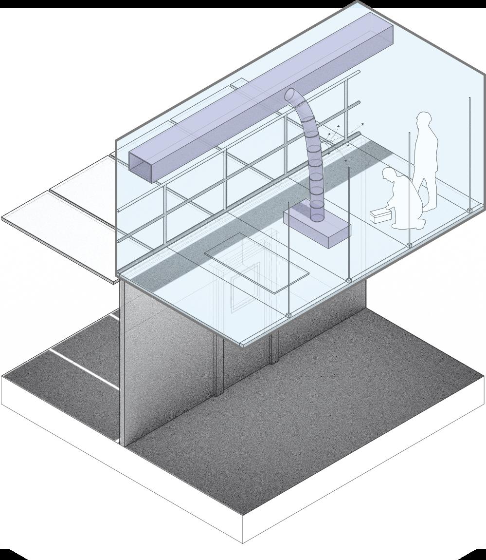
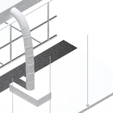
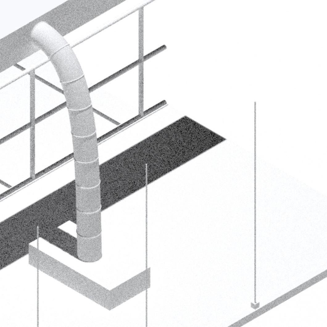
Designing for maintenance and expansion:
A well-designed GMP building does more than meet immediate operational requirements, it also facilitates ongoing maintenance and anticipates future expansion. To reduce the risk of contamination during servicing, the architectural layout should allow maintenance personnel to access equipment without entering cleanroom areas. This can be achieved through the inclusion of maintenance corridors or utility chases: narrow interstitial spaces located behind processing rooms, where piping, valves, and control panels are accessible from the noncleanroom side. Maintenance staff can then perform servicing and calibrations without gowning, maintaining cleanroom integrity.
Similarly, utility systems should be routed so that key control points such as valves, sensors, and connections are accessible from
2
increasing vibrations equipment 1
Figure 11
Figure 12
section view
filled gap, ie. rubberised scrap
floor slab
thickened concrete slab
compacted substrate
service ceilings or dedicated technical spaces. An overhead service deck with separate staircase or lift access allows engineers to avoid production corridors entirely. These features do require additional spatial planning, such as allocating an extra metre behind cleanroom walls, but significantly reduce operational disruption.
Future expansion should also be embedded in the initial design. Structural components can be designed to support vertical extensions or lateral additions. Knock-out panels in exterior walls can signal future doorways or corridor connections, while utility rooms and service routes should be positioned to enable seamless integration with phase two or three expansions. For example, placing a mechanical plant centrally may allow it to serve multiple future wings.
Forward-thinking GMP buildings also include spare capacity in their core systems. Redundancy, such as installing an additional chiller that runs at part load but can meet future cooling demands or installing utility headers with capped ports ready for new equipment, enables faster adaptation to new product lines or client needs. While this approach carries a higher initial cost, it pays off for facilities expecting to grow, particularly for multiproduct environments or contract development and manufacturing organisations
(CDMOs), where production demands frequently shift.
In summary, the structural and architectural foundation of a GMP facility determines its long-term viability. Whether creating a newbuild or retrofitting an existing structure, the goal is to establish a clean-ready shell that supports stringent environmental controls, efficient operations, and flexibility for growth. Addressing structural challenges, enabling ease of maintenance, and planning for expansion from day one ensures the facility remains compliant and adaptable. The next step is integrating the services and environmental control systems that will bring this framework to life and truly support GMP manufacturing.
Figure 13 damaged structure
BUILDING SERVICES AND ENVIRONMENTAL CONTROL
The building’s engineering systems including HVAC, plumbing, electrical, and control systems are the lifeblood of a GMP facility. They create and maintain the required clean and stable conditioned environment, and provide the utilities needed for production. Designing these building services to meet GMP standards is a critical aspect of the project:
HVAC systems and cleanroom environment:
The HVAC system is arguably the most crucial utility in a GMP facility. It controls air cleanliness, room pressures, temperature, and humidity, all of which are tightly regulated. GMP cleanrooms are classified by their maximum allowable particle counts per volume of air (ISO classes) and by microbial limits under GMP grade definitions. The HVAC must therefore filter and supply air to achieve the required class. Typically, high-efficiency particulate air (HEPA) filters (rated to remove 99.97% or 99.99% of 0.3µm particles) are used on supply air to critical areas. For example, an ISO Class 7 (EU Grade C) room might have ceiling HEPA filter units ensuring the air is virtually free of particles.
provide benchmarks. As a rule of thumb, an ISO 8 (Grade D) area might use ≥20 ACH, ISO 7 areas 30–60 ACH, and ISO 5 areas (Grade A) could require 100+ ACH with unidirectional (laminar) flow diffusers over critical points. These rates depend on the room’s size, occupancy, and process; the HVAC design must be tailored through calculations and sometimes computational airflow modelling.
Importantly, the HVAC must maintain cleanliness both at rest and in operation, meaning it can handle the particle load when people and equipment are present and working. Another fundamental HVAC function is maintaining pressure cascades between rooms. Generally, the cleanest areas are kept at higher pressure so that air leaks outwards, preventing ingress of contaminants. For example, a sterile filling room (Grade B background with A workstation) will be at positive pressure relative to adjacent corridors. Conversely, if a process involves hazardous aerosols or potent compounds, that room might be run at negative pressure so that air is drawn in, containing any escape.
Figure 14
The air change rate (number of air exchanges per hour (ACH) in the room) is a key design parameter. Regulations do not always prescribe exact ACH values; the latest EU GMP Annex 1 intentionally does not specify a number, instead requiring a risk-based approach. However, industry guidelines
The HVAC design establishes these pressure differentials (typically on the order of +10–15 Pascals between zones) and includes pressure monitors and alarms to ensure they are maintained. Doors must seal well (often with drop-down sweeps) so as not to compromise pressure when closed. Temperature and humidity control is also essential: most cleanrooms are kept around 18–22°C and 40–60% relative humidity, comfortable for gowned personnel and suitable for product stability. Certain rooms may need tighter control (e.g. low humidity for a powder processing room to prevent clumping). The HVAC system may require dehumidifiers or humidifiers (using clean steam or ultrasonic humidification) to maintain those levels year-round. All air introduced must be conditioned appropriately – often GMP HVAC runs 24/7 to avoid swings in conditions.
Because of the heavy airflow and filtration demands, GMP HVAC systems tend to consume a lot of energy. Designers are increasingly adopting energy efficiency measures such as heat recovery exchangers on exhaust air, variable speed fans that can ramp down when full flow isn’t needed, and
zoning to allow setback in unused areas. Care must be taken that any efficiency step does not risk compliance; for instance, some facilities use a nighttime setback (reducing airflow) only if environmental monitoring confirms conditions remain within limits.
Resilience, through the provision of redundancy in HVAC is another design consideration, since loss of airflow or conditioning could ruin product, critical areas often have backup fans or parallel air handling units. It’s common to design with an N+1 philosophy (having one more unit than needed) for fans, chillers, or boilers so that if one fails, the standby can take over. Similarly, exhaust systems for bio-safety cabinets or fume hoods might have standby fans in case one goes down. The physical building must accommodate these extras (space for a standby AHU, or structural support for double exhaust fans, etc.).
In summary, the HVAC system is the engine that keeps a GMP facility within its environmental specifications. It should be robust, with proper filtration, airflow patterns (generally top-down flow with low-level returns in cleanrooms), and automation to continuously maintain pressure, temperature, and humidity.
The equipment responsible for producing and storing these essential utilities such as stills, reverse osmosis units, boilers, compressors, and gas tanks, is typically housed in dedicated plant rooms or a central utility building. For new construction projects, a common design strategy involves creating a separate technical area. This might take the form of a mechanical floor, a penthouse, or an attached utility annex, intentionally isolated from the GMP production areas. This separation allows for the servicing of noisy or large equipment without the need to enter clean zones.
In retrofit projects, however, it may be necessary to section off a portion of the existing building or construct an extension to serve as a utility room. There must be sufficient room allocated not only for the equipment itself, but also for providing adequate maintenance access around it. For instance, a multi-effect WFI still could require a one-meter clearance on all sides to facilitate filter changes and access to inspection hatches. Similarly, large air handling units often have doors for changing filter banks or servicing fans, and these doors must remain easily accessible, not obstructed by walls. The inclusion of service corridors or catwalks around large tanks and boilers significantly improves both safety and ease of maintenance.
Furthermore, utility equipment may necessitate associated features like floor drains, for example, to manage the wastewater produced by the automatic flush of a Reverse Osmosis (RO) water system. Adequate ventilation is also crucial, such as the exhaust required for a chlorine dioxide generator. While some utilities, like cryogenic liquid tanks and bulk gas cylinders, can be located outside in the yard, the building design must accommodate properly sealed and insulated pipe penetrations to bring these utilities inside.
Clean utilities and plant rooms:
Beyond the necessity of clean air, GMP operations frequently rely on high-purity utilities. These include purified water, WaterFor-Injection (WFI), clean steam, process gases such as nitrogen, oxygen, and carbon dioxide, as well as vacuum or compressed air systems.
A particularly critical utility for many pharmaceutical facilities is clean water. The large volumes of purified water and WFI used necessitate dedicated space for storage tanks and circulation loops, complete with pumps and heat exchangers. Similarly, if the facility utilises clean steam for sterilisation or humidification processes, the boiler and its distribution piping become integral parts of the design. These systems often require stainless steel piping, sloped lines to facilitate drainage, and continuous circulation to maintain the required purity.
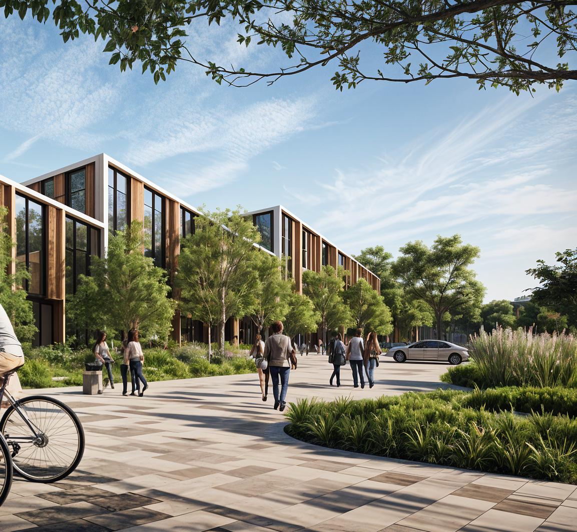
Community green space (image generated by AI)
Figure 15
HEPA filters
The routing of all these utilities must be carefully planned, often utilising a pipe rack or service ceiling dedicated to running pipes throughout the building. Architects collaborate closely with engineers to provide appropriate routes, including vertical shafts and horizontal trays, that effectively connect the plant room to the points of use within the production area. In GMP design, the prevailing preference is to maintain the generation of utilities in separate areas and then pipe in clean utilities, rather than having small generators located within the cleanrooms themselves. This separation offers benefits for maintenance, as utility technicians do not need frequent access to clean areas, and it also helps in isolating any potential leaks or spills away from the product zones.
Electrical power and backup systems:
GMP manufacturing facilities are inherently energy-intensive, placing a premium on highly reliable power supplies. Early in the design phase, a thorough estimation of the electrical load is crucial to ensure the local power supply is adequate. This may necessitate the installation of a dedicated transformer and a high-capacity feed from the electrical grid. It's not uncommon for pharmaceutical plants to exhibit electrical demands in the range of 150–
300 W/m² (15–30 W/ft²) for HVAC and lighting systems alone, with potentially similar or even higher loads required for process equipment such as freezers and centrifuges.
Consequently, the building's main electrical room must be appropriately sized to accommodate multiple distribution panels, motor control centres for HVAC systems, and potentially power conditioning equipment if sensitive instruments demand a stable voltage supply. Furthermore, backup power is typically an indispensable requirement for GMP operations. Critical environments, such as vaccine storage freezers or continuous biologic cultures, cannot withstand power loss without the significant risk of product spoilage or safety hazards.
To mitigate these risks, most GMP facilities incorporate emergency generators and uninterruptible power supplies (UPS). Generators, commonly diesel-engine powered, are sized to support critical loads and often even the entire facility load for a limited duration. While life-safety systems like emergency lights and alarms are legally mandated to have backup power, GMP facilities extend this to include HVAC systems for cleanrooms, key production equipment, environmental monitoring systems, and security systems. These backup generator(s) are usually situated outdoors or within a
Figure 16
multiple distribution panels
transformers
dedicated plant room, equipped with an automatic transfer switch that activates within seconds of a grid power outage. Industry best practice aims for generator start-up and power transfer to occur in under approximately 30 seconds to prevent significant deviations in cleanroom pressures and temperatures. Any brief power interruption is often bridged by UPS units that provide continuous power to critical control systems, ensuring that sensors and computers remain operational until the generator comes online.
During the building design phase, sufficient space must be allocated for the generator equipment and its associated fuel storage tank. Local regulations, such as those in the UK, govern the placement of these elements, including minimum distances from buildings for fuel tanks, the requirement for fire-rated enclosures, and environmental bunding to contain potential spills. These regulatory requirements must be integrated into the overall site planning. Inside the facility, an emergency electrical distribution system, typically featuring separate color-coded conduits or cable trays, is installed to deliver backup power to designated outlets and systems. This ensures that only essential circuits receive power during an outage. Additionally, ventilation and acoustic treatment for generator rooms must be considered, as diesel generators produce exhaust and noise that could potentially disturb both the GMP facility and neighbouring sites if not properly mitigated.
Data infrastructure and monitoring systems:
Modern GMP plants generate and heavily rely on substantial amounts of data for both their operational processes and regulatory compliance. Consequently, the facility design must incorporate a robust IT and automation infrastructure. This typically involves dedicating specific server rooms or IT closets, complete with appropriate cooling systems and access control measures, as well as installing extensive network cabling, including both Ethernet and fiber optic, throughout the production areas.
Key GMP systems that depend on this infrastructure include Environmental Monitoring Systems (EMS) and Building
Management Systems (BMS). The BMS is responsible for controlling and
monitoring critical building HVAC parameters such as temperatures, humidity, and pressures, and may also manage lighting and access control. In contrast, the EMS focuses on capturing GMP-critical environmental data, such as particle counts, microbial sample results, and differential pressures.
These systems often operate under regulations governing electronic records, such as EU Annex 11 and US 21 CFR Part 11, to ensure the integrity of the data.
The physical design of the facility must allocate space not only for the sensors themselves, for example, particle counters that may be wall-mounted or connected via tubes sampling air from various rooms, but also for the central monitoring equipment. Server rooms should be strategically located in low-risk areas, avoiding locations such as flood-prone basements. Ideally, these rooms should have independent cooling systems or at a minimum, temperature monitoring capabilities, as the loss of critical data can be as detrimental as the loss of the manufactured product itself.
Access control and security systems:
The data infrastructure of a modern GMP facility also extends to security systems. Badge readers on doors and security cameras strategically placed in critical areas necessitate careful planning for cable pathways and mounting points. For cameras located within GMP areas, cleanroom-rated housings may be required to prevent particle shedding. If CCTV coverage is a client requirement, camera placement and sightlines must be planned effectively. Often, cameras are positioned in corridors and central manufacturing rooms to monitor safety, quality, and to potentially review any deviation events.
All these interconnected systems, BMS, EMS, and security, typically converge and feed data into central consoles, which might be located in a dedicated control room or a facilities office. This central monitoring point must be factored into the overall space plan. Implementing redundancy in data logging is
also a prudent measure. In the event of a primary system failure, critical data, such as temperature logs, should still be captured by a secondary device or benefit from backup power.
From a design perspective, providing dual power feeds or UPS to data cabinets, along with dual network routes to mitigate the risk of a single cable cut disabling sensors, are important considerations for high-reliability facilities. While the intricate details of the IT infrastructure are typically managed by specialists, the architect plays a crucial role in ensuring that there is sufficient physical space and connectivity, including conduits and cable tray space in ceilings, to accommodate all the digital infrastructure that serves as the building's vital network.
Environmental monitoring & controls:
Closely integrated with both HVAC and IT systems, a GMP facility must incorporate environmental monitoring devices and sophisticated alarm systems. Pressure gauges or digital sensors are strategically installed across pressure-controlled thresholds to provide continuous verification of the pressure cascade. Similarly, temperature and humidity sensors within rooms feed real-time data back to the BMS. Many facilities also employ continuous particle monitoring, particularly in the highestgrade areas such as Grade A and B, utilizing vacuum tubing to draw air samples to a central particle counter. The facility design must meticulously accommodate the mounting of these sensors and the routing of their connections in a manner that preserves cleanroom integrity. This might involve planning for small, properly sealed penetration points for sensor tubes or wiring.
Alarm annunciators, such as warning lights or sirens, are typically placed in corridors or outside room doors to provide immediate alerts if a room's environmental conditions deviate from specified parameters, for example, in the event of a pressure alarm or a door being left ajar. Alarm indicators should be clearly visible but not intrusive and must be constructed from cleanroom-compatible materials.
In GMP facilities, a central building management panel or screen, readily accessible to facilities staff, is a common feature for aggregating environmental readings. Allocating a small control room or a dedicated space within the maintenance workshop for a central panel proves to be highly beneficial. While building services are managed through automated controls, the facility design must inherently accommodate the physical hardware, including sensors, panels, and wiring, that underpins this automation. For example, a flush-mounted wall panel located in a corridor might house the controls for an airlock's interlock system or display an indicator showing the current pressure status; these installations require careful and proper execution.
Fire protection systems:
Although not always explicitly discussed as part of GMP, fire protection is a fundamental building service that demands careful and thorough integration into the facility design. Regulations in the UK, along with requirements from insurers, will mandate the inclusion of fire alarms, fire extinguishers, and often automatic sprinkler systems, particularly in larger facilities.
When incorporating sprinklers within cleanrooms, it is essential to select types that can be recessed and have minimal ledges to prevent particle accumulation; flush-mounted sprinklers with smooth cover plates are commonly employed in these environments. The piping for sprinkler systems must be meticulously sealed where it passes through cleanroom walls or ceilings, utilising appropriate gaskets to maintain the integrity of the clean barrier.
Architects must collaborate closely with fire engineers to ensure that necessary smoke extract systems or fire dampers do not inadvertently compromise the clean environment. In certain critical areas, such as server rooms or solvent storage areas, special fire suppression systems, like inert gas systems, might be considered to avoid potential water damage or adverse chemical reactions. However, these choices must be carefully balanced with GMP requirements. For instance, a gas suppression system will still necessitate vents or door grilles, and the
potential impact of these openings on air cleanliness must be thoroughly evaluated. In summary, fire safety measures are not only mandatory but must also be seamlessly integrated into the GMP layout without creating contamination traps or unsealed penetrations.
Waste management systems:
Handling waste within a GMP facility necessitates a comprehensive approach that encompasses both procedural design, such as segregated waste flows, and the design of appropriate equipment and systems. For liquid waste, particularly if it poses biological or chemical hazards, plumbing infrastructure may include dedicated collection and treatment units.
For instance, biotechnology facilities that generate biohazardous liquid waste often incorporate a kill tank. This is typically a heated and agitated vessel designed to hold waste effluent and sterilise it, usually through heat treatment, before it is discharged. The building design must allocate space for such a tank, often in a lower level or utility area, along with the necessary associated steam supply and drain lines.
Chemical waste, on the other hand, might require neutralisation sumps to adjust its pH before it can be safely discharged into public sewers. While these are fundamentally engineering systems, they necessitate dedicated space and appropriate construction materials, such as acid-resistant floor coatings in a neutralisation room and bunding to contain potential spills.
For solid biohazard waste, on-site decontamination using large autoclaves can be implemented. If this approach is adopted, the autoclave, which might be a pass-through type situated between a GMP area and the waste collection room, must be carefully integrated into the facility layout, and its exhaust and drainage systems properly managed. If waste is intended for off-site transportation without prior treatment, then sufficient cold storage capacity, such as freezers for biohazard bags, or secure bins must be planned, typically within the designated waste staging area.
Corridors and doors leading from laboratories to the waste storage areas should be adequately sized to accommodate wheeled bins and that any lift used for waste transportation is either separate or scheduled to avoid any potential cross-contamination with the movement of clean materials.
Floor drains are an often overlooked, but crucial feature in GMP facilities. GMP production and wash areas may require drains to facilitate cleaning operations, and waste handling areas should have them for effective spill control. Drains located within GMP areas necessitate trapped and often air-gap designs to prevent the backflow of contaminants and are frequently constructed from stainless steel to make them easy to clean.
In summary, the building's services extend beyond the supply of clean utilities to include the safe and effective removal of waste. These waste management systems must be designed to prevent any cross-contamination, such as the migration of vapor from a solvent waste tank into an air intake, and to ensure compliance with all relevant environmental regulations.
All building services should be designed with reliability and cleanliness in mind. Resilience, through the provision of redundancy (backup pumps, dual-feed electrical, spare capacity) is a common theme to allow maintenance without stopping production.
The arrangement of these systems in the building, dedicated plant areas, routed service lines, accessible controls, makes a huge difference to day-to-day compliance. For instance, having a utility corridor means an engineer can calibrate a valve from outside rather inside a cleanroom, which both saves time and reduces contamination risk.
By treating HVAC, utilities, and controls as integral parts of the architectural design, the final facility will be far more robust and easier to manage.
The next section discusses how these services and structural elements translate into the detailed internal layout of cleanrooms and support areas.
INTERNAL LAYOUT AND CLEANROOM DESIGN
Inside the building, the focus turns to the detailed layout of rooms, corridors, and clean zones that directly support GMP operations.
This is where architectural design principles for contamination control are most visibly implemented. A successful internal layout ensures that different processes do not cross-contaminate each other, that people and materials move through the facility in a controlled manner, and that the environment within each space meets the required classification.
Personnel and material flows:
GMP layouts typically separate flows of people and materials. Personnel flow is arranged so that staff enter from general areas into gowning sequences and then into clean corridors and rooms.
There may be separate entry sequences for different classes of staff (e.g. maintenance personnel might enter through a different route to reach technical areas without going through cleanrooms).
Material flow is arranged starting from a loading/unloading zone. Raw materials are usually brought into a warehouse or reception area, then into quarantine storage. From there, materials pass via material airlocks into preparation or dispensing rooms before going into production areas. After processing, finished products exit via their own airlocks to a packing area or outgoing quarantine.
Importantly, dirty or waste items (like used gowning, waste bags) should exit via separate routes or at separate times. The internal corridors can be designated as “clean corridor” for materials and personnel moving in, and perhaps a “soiled corridor” for waste moving out – or a single corridor can be used with a strict schedule and cleaning in between.
In many modern facilities, a unidirectional flow is enforced: everything moves logically forward from input to output. For example, once an item has entered a Grade C
production area, it should not go back out through the Grade D change room; instead, it would leave via a separate exit path to waste handling. Additional corridors or staircases may be needed to achieve this segregation. Spatial clear marking (through colour-coded floors or signage) is often used to delineate different flow paths and zones.
Segregation of processes and containment:
Within the facility, different processes might need to be isolated from each other depending on the product. For multi-product plants, campaign segregation is important; only one product is processed in a given area at a time, or completely separate suites are provided for each product. If the products can cross-contaminate (e.g. two different potent drugs), separate HVAC zones and physical barriers are needed between processing areas.
In facilities that handle potent compounds or biological agents, containment becomes a key layout driver. Certain rooms might be designed as containment labs (with negative pressure relative to corridors, airlocks in and out, and once-through air that doesn’t recirculate) to ensure nothing hazardous escapes. This could be the case for a cytotoxic drug formulation area or a live virus lab. These rooms might be clustered in a specific wing with its own dedicated corridor to keep them distinct from other manufacturing areas.
Another aspect is utilities segregation: potent product areas might have dedicated vacuum systems or drain systems separate from the rest of the facility to avoid crosscontamination through those routes. From an architectural standpoint, providing physically separate spaces or dividing walls up to the roof (to prevent above-ceiling mixing of air) are solutions.
One concept used in some multipurpose facilities is the “ballroom” design; a large open cleanroom where multiple steps are done in portable equipment with closed systems, rather than separate rooms for each
cluster isolated in its own wing/block
dividing walls up to the ceiling
airlocks dedicated drain systems
negative pressure relative to corridors
step. This offers flexibility but requires that all processes in the ballroom be compatible or enclosed to prevent cross-contamination. If a ballroom approach is used, the layout must still ensure the necessary background environment and unidirectional flow around equipment, possibly using mobile partitions or curtains for partial segregation.
In general, functional adjacencies in the plan should follow GMP logic: incompatible functions are kept apart, while those that flow from one to the next are adjacent. For instance, a weighing booth (where raw ingredients are dispensed) is typically next to the material airlock and the compounding room, but far from any packaging or office area.
Figure
Support areas and personnel facilities:
Not every space inside is a cleanroom, but their design still impacts GMP operations. Gowning rooms deserve special mention: these are the entry points to each grade and must be sized to allow personnel to properly don or doff protective clothing without contaminating it. They often have benches that act as a barrier and storage for gowns, gloves, and consumables must be built-in. The layout might include separate change rooms, depending on facility policy, and often an air shower or blow-off room is placed after gowning for the highest grades (a chamber that blows HEPA air to dislodge any particles on the suit before entering Grade B/A).
Equipment airlocks or delivery vestibules might be needed for bringing in large equipment or maintenance tools. These could be essentially the same as material airlocks but sized for a pallet or cart. Planning these as part of circulation is important so that a fermenter or filling machine can be moved in and out without dismantling walls. Offices and labs that are inside the GMP facility (like a sampling laboratory or a control room overlooking production) should be separated by corridors or glass partitions, so that administrative activities don’t interfere with clean areas yet are conveniently close.
Often, a corridor with windows into the cleanrooms is provided for supervision. This allows personnel to oversee operations without entering the clean zone. Such corridors need to be at lower pressure than the cleanroom and are usually at least Grade D or unclassified but kept clean.
Social spaces (break rooms, toilets) are ideally located in the non-GMP part of the building (front- office area), so staff exit to a neutral zone to eat or use restrooms, then regown when returning. If that’s not possible, there may be transition airlocks between GMP corridors and any amenity rooms.
In designing the internal layout, designers must iterate closely with process engineers and end-users. Good practice is developing flow diagrams and adjacency matrices to map out the movement of people, materials, waste, equipment, and even air. Then the floor plan is arranged to satisfy those flows with minimal backtracking or crossover. By doing so, the final layout becomes a physical manifestation
of GMP rules: it inherently reduces contamination risk by design.
The purpose of every space is clear and supports either the production process or the maintenance/utility of the facility. When inspectors walk through such a facility, they should be able to literally trace the product path and see that at each point, measures are in place to protect the product from contamination and mix-up.
CLEANROOM MATERIALS AND FINISHES
The choice of materials and finishes for the interior of a GMP facility is a crucial aspect of design. Surfaces must withstand frequent cleaning with strong disinfectants, and they must not shed particles or harbour microbial growth. GMP regulations call for smooth, impervious, and cleanable finishes on walls, floors, and ceilings. This often determines the selection of construction materials, fixtures, and even furniture in clean areas:
Floors
Cleanroom floors are typically seamless and non-porous. Common solutions include resinous flooring systems like epoxy or polyurethane coatings applied monolithically over concrete. These create a continuous surface with no grout lines (unlike tile) and can be coved up at the wall junctions to eliminate corners where dirt can accumulate. The flooring should be durable against foot and trolley traffic, and resistant to chemicals (e.g. sporicidal agents, acids, solvents if used in the process).
In some facilities, especially where electrostatic discharge is a concern (electronics or some powder processing), an Electrostatic Discharge (ESD)-safe vinyl or epoxy floor may be used. The key is that flooring is easy to clean (can be mopped or scrubbed without seams trapping residue) and does not generate dust.
In wet process areas, the floor might be sloped to drains and have a textured finish for slip-resistance, but it still needs to be cleanable (so textures are kept mild, and floors are often inclined just enough for drainage).
Walls
Cleanroom walls are typically either built from drywall (plasterboard) with a special coating or assembled from modular cleanroom panels. Modular panel systems are widely used in pharma facilities. These are prefabricated insulated panels (often steel or aluminium skinned) with baked-on glossy
Learning Lab
(image generated by AI)
finishes. They lock together with almost invisible joints and have built-in coving at floor and ceiling transitions. The advantage of modular walls is precision and quick installation, plus they can be demounted if layouts change.
Traditional drywall can also achieve GMP standards if finished properly: usually a fiberglass-faced gypsum board is used (to avoid paper that could foster mould), with all joints taped and sanded smooth, then coated with a durable, epoxy paint. Whether panels or drywall, smoothness and solidity are vital; walls should not have ledges, exposed studs, or porous surfaces.
Stainless steel is sometimes used for wall protection in heavy traffic areas or around wet process equipment, but large stainless wall surfaces can be costly and are typically reserved for small sections (like within a biosafety cabinet interior or niches). Corners between walls and floors/ceilings are addressed with coving; a concave curved trim that eliminates the 90° angle to aid cleaning. Similarly, any wall openings (for pipes or sockets) must be completely sealed with gaskets or caulking. Flush-mounted utility panels are preferred to surface-mounted boxes.
Ceilings
Ceilings in cleanrooms are often a composite system. In many facilities, a suspended cleanroom ceiling grid is used, which holds HEPA filter units and light fixtures in its panels. The grid and panels are cleanroomrated (smooth, non-shedding).
Some modern designs use walkable ceiling panels, essentially creating an interstitial floor. In that case, the underside of the walkable panel acts as the cleanroom ceiling, usually a metal pan with a clean finish. All fixtures (lights, filters, sprinklers) are mounted flush within it.
If not walkable, the ceiling might be gypsum board or stretched PVC in lower-grade areas, but typically a standard is set facility-wide for consistency. Any lights are flush and sealed
(lighting fixtures come with cleanroom troffers that sit flush and have gasketed trims). Likewise, air return grilles are flush, and often along the walls near the floor.
Every penetration, whether for sprinkler heads, sensors, or passthrough ducts, should be airtight and neatly detailed. The goal is a ceiling that is effectively solid except where designed components (filters, lights) are, and those components are designed to not shed particles. The ceiling surface should not accumulate condensation (hence controlling humidity and using insulated panels to prevent condensation on the underside from colder spaces above).
Doors and windows
Doors in GMP areas are typically heavy-duty, with smooth flush surfaces and minimal crevices. Metal doors with powder-coated finish or laminate-faced doors are common; timber is avoided unless fully encapsulated. Door frames are usually set flush with wall panels, and many cleanrooms use flush glazing for any observation windows.
For example, a window might be a doubleglazed unit mounted flush with the wall on both sides, often with a slight tint or privacy film if needed. This prevents any ledge around the window frame where dust could settle.
Doors often have automatic closers and sometimes automation (to reduce touching and to enable airlock sequences). Kick-plates or protection panels at the bottom are flushmounted. Hardware (hinges, handles) should be simple and easy to clean; lever handles or even hands-free paddle handles are preferred over ornate shapes.
In higher grade airlocks, electromechanical interlocks on doors are installed; the design should account for wiring those in and placing indicator lights if needed to show door status.
Also, thresholds should be flush (no raised saddles) to allow carts to pass without jolting, unless a slight ramp is needed for containment (rarely, a door might have a small sill if liquid containment in a room is required, but even then, a ramped or recessed solution is used to avoid a step).
Fixtures and furniture
Any built-in furniture or equipment in GMP rooms must also adhere to cleanability principles. For instance, cabinets or counters in a sampling room should have sloped tops (so dust doesn’t accumulate) or reach the ceiling, and their front faces should be flush with no recessed pulls. Often stainless steel or powder-coated metal furnishings are used.
In many clean areas, less is more; the design tries to avoid built-ins unless necessary, and mobile, easy-to-clean stainless steel tables or carts are used instead.
If sinks or benches are required (for example in gowning rooms or labs), those with minimal joints (integral backsplashes, for example) and sealed edges should be specified. Penetrations for pipes or cables must be sealed with cleanroom grommets or caulk; for larger pass-throughs, prefabricated GMP wall ports are available.
Surface finishes and coatings
Paints and coatings for GMP should be durable and non-reactive. Epoxy or polyurethane paints are common on drywall and concrete because they form a hard, glossy finish that stands up to repeated cleaning with disinfectants like alcohols, peroxides, or bleach solutions. They also resist chipping better than standard latex paint.
Some facilities use antimicrobial additives in paints. While not a substitute for cleaning, these can help inhibit microbial growth on surfaces in between cleaning cycles. Light colours (white or light grey) are often used to make dirt easily visible and to enhance lighting. However, some labs may use different wall colours to delineate areas or for aesthetic reasons, as long as the finish quality remains GMP-grade.
Floor markings (like epoxy stripes) might be employed to mark different zones within a large area (for example, a line on the floor where one must change shoe covers). If used, these markings should also be low-profile and sealed.
Chemical Resistance and Cleaning
All materials must stand up to the cleaning regimen. GMP facilities undergo daily cleaning and sanitisation, and regular more intense disinfection (for sterile areas, sometimes even fumigation with vaporised hydrogen peroxide). Therefore, selecting materials that do not degrade or emit particles under such conditions is critical. For example, polycarbonate light covers might craze with alcohol over time – tempered glass would be better. PVC flooring might not tolerate certain solvents – hence
the shift to epoxy floors. Stainless steel (304 or 316 grade) is used for any surfaces that might contact harsh chemicals or high heat during sterilisation.
Cleaning agents (like quaternary ammonium compounds, phenolics, etc.) expected to be used should be reviewed to ensure compatibility with floor and wall finishes. No exposed wood or gypsum should be present in cleanrooms; even backing structures should be encased because those materials can grow mold if they get moist. Utilities that run through clean areas (pipes, trunking) should either be boxed in with metal enclosures or at least painted and sealed.
Wherever two materials meet, provide a gasket or sealant to make it continuous. Silicone or polyether sealants are commonly used in cleanrooms to seal between floor and wall or around penetrations. These must be non-nutrient for microbes and should not emit volatiles once cured (low VOC formulations).
By using appropriate finishes, smooth, monolithic flooring, flush walls and ceilings, radiused corners, and sealed utilities, the facility will not only meet GMP requirements but also be easier to maintain. During operation, these surfaces will be regularly inspected by QA personnel. Any chipped paint, rust, or cracks will be flagged as potential contaminants. Thus, investing in high-quality materials upfront reduces maintenance issues later.
The professional appearance of well-finished cleanrooms also gives regulators confidence; it demonstrates that quality was built into the environment. In many ways, the detailing of cleanroom finishes is where architectural craftsmanship meets GMP compliance. A seemingly minor detail, like a door frame caulked on all sides, can be the difference between a perfectly cleanable room and one that harbours hidden bioburden.
Architects should work closely with contractors during construction to enforce these finish standards. Sometimes specialist cleanroom installers are engaged for critical steps like flooring and panel installation. The end result should be a facility where every surface gleams, and corners or crevices simply do not exist to trap dirt.
CONCLUSION
Designing GMP-compliant spaces is a complex task that stretches from macro-scale planning of sites and utilities down to microscale details of interior finishes. For developers, agents and designers new to this field, it involves learning to think GMP: understanding concepts like cleanroom grades (A/B/C/D or ISO classes), pressure cascades, and validated utility systems, then translating those into the language of building layout, materials, and MEP (mechanical/ electrical/plumbing) design.
The architect must constantly collaborate with process engineers, quality consultants, and regulatory experts to ensure the facility’s design will satisfy not only the functional needs of production but also the stringent expectations of regulators. Global standards (from MHRA/EMA in Europe, FDA in the US, WHO internationally, and ISO for cleanrooms) provide the framework to protect patient and consumer safety, but it is the role of design to implement those standards in practical and often innovative ways.
Whether it’s a shiny new build optimised from the ground up, or the retrofit of an old warehouse that must be surgically transformed, the end goal is the same: a facility that consistently produces highquality, safe products with minimal risk of contamination or mix-ups.
In achieving this, one cannot forget considerations of the facility’s full life cycle. A GMP plant is a long-term asset; it must not only pass its initial validation but remain reliable and accommodating for years to come. This is why we emphasise designing for maintenance, expansion, and flexibility.
Features like accessible service spaces, spare capacity in systems, and reconfigurable layouts help to future-proof the facility.
Real-world projects have shown that with careful planning and interdisciplinary teamwork, even daunting challenges (like
converting a cramped office building into a state-of-the-art pharmaceutical plant) can be overcome. Often, the lessons learned on one project inform the next, for example, a difficult retrofit might lead to a standard approach of including a structural grid for any future ceiling loads.
Success in GMP design comes from a holistic approach: marrying architectural functionality (people and material flow, space efficiency, safety) with engineering performance (clean air, precise utilities, environmental control) and compliance documentation.
By following the principles outlined in this guide, from site security and airlock placement to flush finishes and redundant HVAC, designers can create GMP facilities that not only pass inspections but also operate efficiently and safely from day one. Each industry sector (pharma, biotech, advanced food, cosmetics, etc.) has its own nuances, but all share the GMP ethos of “quality by design.”
Ultimately, a well-designed GMP facility provides a foundation upon which high-quality products can be reliably manufactured to improve health and well-being, ensuring the built environment is an active partner in the pursuit of GMP compliance and excellence.
SOURCES
European Medicines Agency (EMA/MHRA), EudraLex Volume 4: EU Guidelines for Good Manufacturing Practice, including Annex 1 (2022) for sterile manufacturing
World Health Organization, WHO GMP – Main Principles for Pharmaceutical Products (Annex 2, WHO Technical Report Series)
U.S. Food & Drug Administration, 21 CFR Parts 210–211: Current Good Manufacturing Practice regulations for drugs
Zamann Pharma Guide, “Top 10 Steps for Qualifying a New GMP Facility” – overview of facility requirements and qualification (Aug 2024)
Mecart Cleanrooms Technical Article, “Building a GMP Facility: 8 Cleanroom Requirements” – clean design features (flush surfaces, airlocks, etc.)
Outsourced Pharma (Scott Strom, 2021), “Key Considerations for cGMP Building Conversions” –insights on retrofitting buildings for GMP use
Cleanroom Technology (Jason Teets, Nov 2023), “Converting Buildings to House Cleanrooms for cGMP Manufacturing” – case studies and retrofit strategies
BioProcess International (Sue Cooke, May 2021), “Facilities for Novel Therapies: Demystifying Design and Engineering Requirements” – discusses modular design and multi-product facilities
BioProcess International, 2011, “Multiproduct Facility Design” – industry forum on designing flexible multiproduct plants
HOK Architects (2020), “Designing Developer-Led Lab Projects (Speculative Lab Facilities)” – guidance on speculative life science buildings
D. Magazine (Dec 2024), “DFW ‘Missing Middle’ in Life Sciences – Bridge Labs example” – example of a speculative lab facility project