Technical Information
Mounting Instructions

part, is not permitted without our written consent.

Technical Information
Mounting Instructions
part, is not permitted without our written consent.
1.1 Function and application
The gear rack installation instructions describe how the gear rack drive components are fitted.
1.2 Target group
SCHNEEBERGER has defined the following user groups:
• Machine builder
Machine end user
The machine builder is SCHNEEBERGER's direct customer. They fit the SCHNEEBERGER component into their machine and sell the end product to end user. These installation instructions are intended for machine builders.
1.3 Additional literature
Dimensions and other details about the gear racks are in the gear rack catalogue. (http://www.schneeberger.com/en/)
2 For your safety
2.1 Authorised staff
Gear racks must only be fitted by appropriately trained specialists, such as fitters who have read and understood these instructions.
2.2 Intended use
SCHNEEBERGER gear racks are components for precise linear movements. SCHNEEBERGER gear racks must only be used in the temperature range of -40°C to +80°C. SCHNEEBERGER gear racks must not be used as safety components.
2.3 General safety and protective measures
Store gear racks in their original packaging and protect them from damp and damage.
When fitting all components must be kept at the same room temperature.
Only use original SCHNEEBERGER parts for repairs.
Comply with country-specific regulations, standards and guidelines for accident prevention. To ensure that the products work properly also observe the instructions on profile and location tolerances, lubrication and environmental conditions.
2.4 Environmentally responsible behaviour
Do not allow lubricants to end up in the environment and dispose of in accordance with countryspecific regulations.
3.1 Basic points
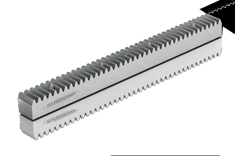
Gear rack drives’ main feature is their high level of efficiency. They are the best choice for high axial forces. This drive rigidity is constant over the whole length.They are also very cost effective for long strokes of more than 2 m.
With a rack and pinion system a slideway is driven by the pinion running on a fixed gear rack. There is a basic difference between straight and helical toothed gear racks. Apart from typical dimensions, SCHNEEBERGER supplies any cross sections with metric or module pitches. The maximum one-piece length is 3000 mm. This means that they can be joined in any sequence.
The tooth rack can be milled or ground depending on the customer's requirements. A particular feature is that different materials and hardening processes can be used. Depending on the load to be applied you have a choice of soft, induction or casehardened and nitride hardened gear racks.
3.2 Components
The gear racks are described in detail by the order description. Further details are contained in the associated drawing.
When dispatched gear racks are protected from corrosion and should not be stored in their original packaging for more than a year. Gear racks must be stored in dry, heated storerooms.
You must bear the following points in mind when transporting:
• Transport in the original packaging. Bending effects must be avoided with long gear racks
• Protect from impacts and moisture
5.1 Cleaning
The machine and supporting surfaces should be degreased, cleaned and prepared with an oil stone. When they are supplied the gear racks already have corrosion protection. This must be removed immediately before fitting. They should be fitted in a clean, dry environment because dirt will have a detrimental effect on their operation. The mounting surfaces of the slideway must be thoroughly cleaned and then prepared with an oil stone.
The grease must not be removed from the tapped fixing holes in the machine bed because otherwise the friction when tightening will be too great and the screw's required preload force will not be reached. In this case apply a little oil.
After cleaning the gear racks must be placed on the machine bed so that the temperatures can adjust.
5.2 Tools and aids required
Personal protective equipment, protective gloves
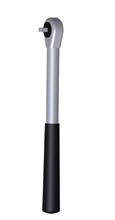
• Torque wrench
• Fixing screws
• Oil stone
• Cleaning cloths
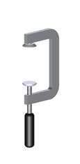
• Screw clamps
• Module and angled mounting plate
Protective gloves must be worn when handling gear racks. This will prevent cutting injuries and avoid contact corrosion.
A lifting device may sometimes be necessary to fit the gear racks. You must ensure that suitably sized equipment is available. Cylinder screws and dowel pins are required for fixing the gear racks, as described in the table below.
Screws of strength class 10.9 must be used for soft or inductively hardened gear racks and strength class 12,.9 for case-hardened and through-hardened gear racks.
The permissible tightening torques are listed in Chapter 12.
* we recommend dowel pins with an internal thread for ease of removal.
5.3 Checking the delivery schedule
The gear racks should be checked for dirt and external damage. Damaged or dirty gear racks must not be installed.
6.1 Fitting the first and additional gear rack(s)
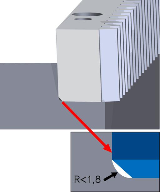
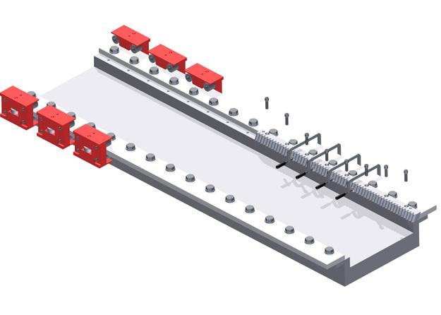
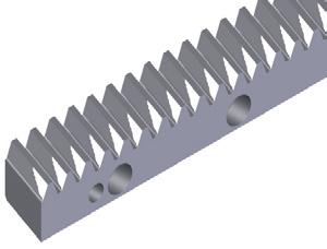
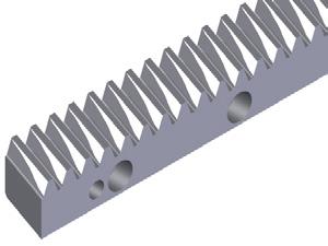
The gear rack has a chamfer between the installation and the contact surfaces (Picture 1) in order to ensure it abuts the machine bed as cleanly as possible. The gear rack will be aligned in the best possible way if the stop bar is first of all aligned with the guide blocks. Attach the first gear rack to the machine bed, align it centrally and clamp it to the installation surface with the screw clamps (Picture 2).

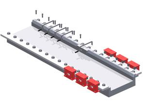
Attach the fixing screws but do not tighten them fully.
• Position the gear rack's contact surface in accordance with the guideway of the machine.
• Then tighten the fixing screws with an appropriate torque from the middle outwards (see Chapter 12).
• The previous steps must be repeated for the remaining cylinder screws. The screw clamps can be undone.
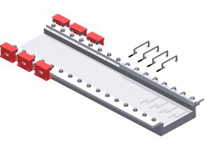
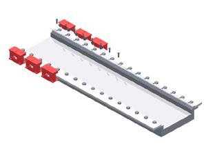
The flatness and joints must be checked before the next gear rack is attached. Fit the next gear rack and position it over the corresponding fixing holes.
• Attach the assembly jig and clamp it lightly.
• Clamp the gear rack to the machine bed in the area of the fixing holes. Insert the first fixing screw in the direction of installation.
• Tighten the fixing screw with an appropriate torque in the direction of installation.
• Repeat the previous steps for the remaining fixing screws.
• Undo all screw clamps and the assembly jig.
Note: We recommend using a screw securing adhesive (e.g. Loctite 243) to secure the fixing screws.
Gear racks can be fitted in any order. If the gear rack is shorter than 1 m dowel pins are also necessary. Ensure that only gear racks with identical order codes are used for the same application.
The systems must be aligned in an axial direction over the tooth racks in such a way that the pinion does not jam when rolling over the joint. To do this the spacing of the teeth must be set at the joint so that it corresponds with the spacing of the remaining racks and thus moves within the permissible individual pitch error of the adjacent rack.
To do this the BZM assembly jig should be used for installation. This is a short rack segment with counter gearing. After the guide rails have been orthogonally aligned, they are pulled into the gearing using a clamp and in this way the systems are axially aligned with one another. To do this at least one of the aligned segments must be moved slightly in an axial direction.
If the torque is transferred via a tensioning gear or a tensioning system in which two gear wheels are meshed on the same gear rack, the whole torque must not exceed the push force of the screws.
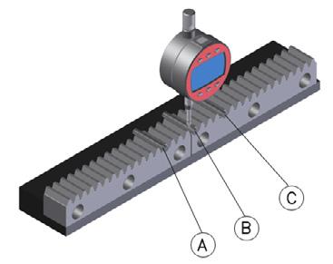
6.2 Checking the running accuracy
• Fix the dial gauge bracket onto the machine slide. Put the measuring roller in the joint (B) and in the teeth rack on the left (A) and right (C) of it and measure the difference in height in each case. The permissible height differencedepends on the quality of the gear racks.
• The joint (B) should be between the upper and lower limit (A and C) of the tooth racks.
• In the event of deviations align the parallelism up to a minimum measurement by reaching the desired height tolerance on the dial gauge by using a copper tapered punch to hit the first screw hole for the previous gear rack away from or in the direction of installation.
After the joint has been checked successfully, clamp the screw clamps on again tightly and tighten the cylinder screws with full torque (see 6.1).
• Repeat the previous steps with the other gear racks.
• Remove the screw clamps.
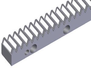
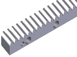
6.3 Pinning
Drill the pin holes to match the gear rack holes in the machine bed.
• Ream the all the holes to the correct tolerance dimension for the dowel pins. see 5.2.
• Remove any swarf with a vacuum cleaner.
• Finally fix the gear racks with cylinder pins.
Note: We recommend dowel pins with an internal thread for easier removal (see 10).
6.4 Final check
• If necessary remove the grease from the tooth flanks of the gear rack.
• Paint the tooth flanks with touch up paint.
• Move the machine table several times so that the pinion runs over the painted tooth flanks.
While doing this check that the tooth rack moves easily.
• The energy expenditure and the running noise must be the same over the whole travel distance.
• There must be no impact at the intersections (joint).
• Check the area where the paint was removed from the tooth flanks.
• Assess the alignment of the gear using the contact pattern shown in the pictures below.
• If necessary adjust the alignment of the gear.
• Check the gear racks at the joint for pitch accuracy.
Sufficient lubrication with a lubricant suited to the conditions of use is necessary to ensure that the rack drive continues to work properly. Lubrication protects from wear and corrosion and reduces friction.
Apart from the initial lubrication the equipment must be re-lubricated regularly during installation.
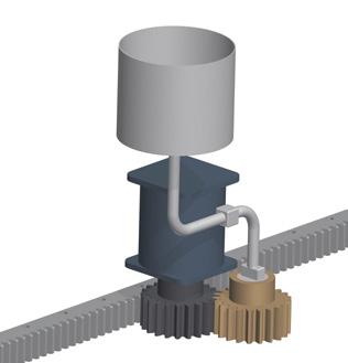
Normally electrically-driven lubrication cartridges are used for lubrication. Lubrication greases NLGI 00 to NLGI 0 are applied to the drive pinion or the gear rack with a felt pinion. Please note that the felt pinion hardens over time and is subject to natural wear and tear. Therefore it must be checked at regular intervals and replaced if necessary.
A typical lubricant is Klüber Microlube GB 0.
Too little lubrication shortens the service life of the drive system. Therefore, always ensure that the machine is lubricated adequately.
9 Maintenance
9.1 Shutting down, preparation
Inadequate lubrication shortens the service life of the tooth system.
You must ensure that the pinion between the pinion and gear rack is set correctly.
When freewheeling the guide block should be moved evenly over the length of travel (ensure that it has not been distorted during installation). With vertical axes the machine table must be secured according to the instructions.
In the event of jams the distance between the gear rack and the guide should be measured again using a dial gauge.
The machine in which the drive system is installed must be shut down during maintenance. The machine must be disconnected from the power supply before maintenance work. With vertical axes the slideway must be secured according to the instructions.
9.2 Visual check
Check the whole drive system for external damage and leaking lubrication by a thoroug visual check.
• The pinion and gear rack must be cleaned.
• The whole drive system must be checked for external damage and leaks with a thoroug visual check.
• Defects or leaking parts must be repaired immediately.
10.1 Preparatory measures
10.2 Removing the gear rack
Shut down the machine in which the drive system is installed. The machine must be disconnected from the power supply before you start work. Ensure that it is possible to dismantle the gear system without any risk to people or the machine.
The gear racks and gear unit must only be dismantled by trained specialists with the necessary knowledge. With Z axes the machine table must be secured as in the instructions.
The positive locking device on the machine table must be disconnected when dismantling the gear racks and the gear unit. If the machine table is not secured properly for Z axes, it may drop due to its own weight and cause damage to people and equipment.
The fixing screws must be undone. After that the gear rack can be removed from the pinned fitting with a suitable tool.
• Remove the gear racks carefully so as not to damage the gear system and adjacent parts.
10.3 Replacing spare gear racks
• Only original spare parts must be used. SCHNEEBERGER assumes no liability for non-OEM parts.
When replacing gear racks use new screws (see 5.2) and pins to fix them.
• Now fit the spare gear racks in accordance with 6.
• Select the next larger dowel pins than specified in 5.2 (only the standard sizes are given in 5.2)
• Ream all the holes to the correct tolerance dimension
• Finally fix the gear racks with the dowel pins
Lubricants are hazard substances that could contaminate the soil and water. Dispose of the lubricant in accordance with the national guidelines in force. Do not mix polyglycol with mineral oils that are intended for recycling.
Gaskets must be disposed of as composite materials (metal/ plastic).
Separate the drive system as far as possible into:
• Steel
• Aluminium (Housing; cover) and Non-ferrous metal (motor coils).
Hoses must be disposed of in the same way as plastic.
Felt gear wheels must be disposed of in the same way as residual oilcontaining waste.
The tightening torques specified for headless screws DIN EN ISO 898-1 are arithmetical values and do not apply to friction factor μ=0.125.
Screws of strength class 10.9 must be used for soft or inductively hardened gear racks and strength class 12.9 for case-hardened and through-hardened gear racks.
A more even preload force is obtained if the screws are lubricated with a grease containing MoS2 and they are tightened using a torque wrench.
Note:
When using greases the friction factor can drop by a half. The torques must be reduced accordingly.
to
SCHNEEBERGER COMPANIES
SWITZERLAND SCHNEEBERGER AG
Lineartechnik St. Urbanstrasse 12 4914 Roggwil/BE
+41 62 918 41 11
+41 62 918 41 00 info-ch@schneeberger.com
CHINA SCHNEEBERGER Precision Motion System Asia Pacific 1/F, F Building, Hongfa Science Park, Tangtou Community, Shiyan Street, Boan District, Shenzhen, P.R.C 518108
深圳市宝安区石岩街道塘头社区 宏发科技园F栋一层 邮编 510108
+86 755 3352 5881 info-cn@schneeberger-sz.com
GERMANY SCHNEEBERGER GmbH Gräfenau 75339 Höfen/Enz
+49 7081 782 0 +49 7081 782 124 info-d@schneeberger.com
CHINA
SCHNEEBERGER (Shanghai) Co., Ltd. Rm 606, Shang Gao International Building No. 137 XianXia Road 200051 Shanghai
施耐博格(上海)传动技术有限公司 上海市长宁区仙霞路137号 盛高国际大厦606室 上海 200051
ITALY SCHNEEBERGER S.r.l. Via Soldani 10 21021 Angera (VA)
+39 0331 93 20 10 +39 0331 93 16 55 info-i@schneeberger.com
KOREA
SCHNEEBERGER Korea Ltd. 5F-E01, 10 Chungmin-ro, Songpa-gu, Seoul, 05840 Republic of Korea
USA SCHNEEBERGER Inc. 44 Sixth Road, Woburn, MA 01801-1759
+1 781 271 0140 +1 781 932 4127 info-usa@schneeberger.com
SINGAPORE SCHNEEBERGER Linear Technology Pte. Ltd. 38 Ang Mo Kio Industrial Park 2 #01-04, Singapore 569511
INDIA Schneeberger India Pvt. Ltd. 188/4, Bommasandra Industrial Area, Bommasandra, Bangalore 560099 India
+91 22 6461 0646 +91 22 6461 1756 info-in@schneeberger.com
TURKEY SCHNEEBERGER LINEER TEKNOLOJİ Tic. ve Ltd. Şti. Ataköy 9. Kısım Mah. Yüzücü Talat Yüzmen
JAPAN Nippon SCHNEEBERGER K.K. Itoyu Bldg Toranomon 7F 3-20-5 Toranomon, Minato-ku Tokyo 105-0001
日本シュネーベルガー株式会社 〒105-0001
東京都港区虎ノ門3-20-5 クレイン虎ノ門ビル7階
+81 3 6435 7474 +81 3 6435 7475 info-j@schneeberger.com
www.schneeberger.com
+86 21 6209 0027/37 +86 21 6209 0102 info@schneeberger-sh.com
www.schneeberger.com/contact
SCHNEEBERGER SALES DEPARTMENTS
AUSTRIA AND SOUTH EAST EUROPE +41 62 918 41 11 info-a@schneeberger.com
POLAND, SLOVAKIA, CZECH REPUBLIC +420 6 0278 4077 info-cz@schneeberger.com
BENELUX +31 6 5326 3929 info-nl@schneeberger.com
RUSSIA, BELARUS, UKRAINE +7 985 960 85 53 +38 050 407 6789 +37 529 860 0410 info-ru@schneeberger.com
슈니베거코리아 유한회사 05840 서울시 송파구 충민로 10 가든파이브 툴관 5층 5-E01 + 82 (0)2 554 2971 +86 21 6209 0102 info@schneeberger-sh.com
CZECH REPUBLIC
SCHNEEBERGER Mineralgusstechnik s.r.o Prumyslový park 32/20 350 02 Cheb – Dolní Dvory
+ 65 6841 2385 + 65 6841 3408 info-sg@schneeberger.com
Sokak No:6
Yunus Emre Sitesi S3 A-Blok D:2 Bakirkoy 34158 Istanbul Turkey +90 (0)
PROSPECTUSES
COMPANY BROCHURE CUSTOMIZED BEARINGS GEAR RACKS
Linear bearings and Recirculating units MINERAL CASTING SCHNEEBERGER MINISLIDE MSQscale
+420 354 400 941 +420 354 400 940 info-mineralguss@schneeberger.com
CHINA SCHNEEBERGER Changzhou Precision Systems Co. Ltd. No. 137 Hanjiang Road 213022 Changzhou
施耐博格(常州)测试系统限公司 汉江路137,常州新区,常州 213022
+86 519 8988 3938 info-mineralguss@schneeberger.com
GERMANY A.MANNESMANN MASCHINENFABRIK GmbH Bliedinghauser Str. 27 42859 Remscheid +49 2191 989-0 +49 2191 989-201 mail@amannesmann.de
DENMARK, SWEDEN +31 6 5326 3929
info-nl@schneeberger.com
SPAIN, PORTUGAL ANDORRA +34 69 559 05 99 info-es@schneeberger.com
FRANCE +33 6 33 12 14 26 info-nl@schneeberger.com
GREAT BRITAIN +44 74 63 89 85 08 info-uk@schneeberger.com
MINI-X MINIRAIL / MINISCALE PLUS / MINISLIDE MONORAIL and AMS profiled linear guideways with integrated measuring system MONORAIL and AMS application catalog POSITIONING SYSTEMS
A.MANNESMANN A member of SCHNEEBERGER linear technology
www.schneeberger.com