even in part, is not permitted without our written consent.
1.1
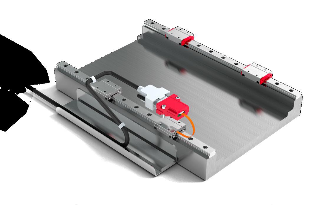
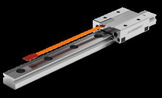
These instructions describe installation of MINISCALE PLUS guideways with integrated measuring system.
Supplementary Literature: MINI-X product catalog
1.2 Authorized Staff
MINISCALE PLUS guideways must only be assembled by appropriately trained specialists who have read and understood these instructions.
1.3 Intended Use
MINISCALE PLUS guideways can only be exposed to the approved environmental influences (see product catalog).
1.4 General Safety and Protective Measures
• Before working on electrical equipment, switch off or disconnect the power supply and ensure that it cannot be switched on or connected again unintentionally.
• Country-specific regulations, standards and guidelines for accident prevention must be observed.
1.5 Environmental Protection
• MINISCALE PLUS is sensitive to electrostatic discharge! The electronics can be damaged if precautions are not taken against ESD; ESD regulations should therefore be observed when handling ESD-vulnerable parts (EN 100015-1).
• Do not store the products outdoors, and protect them against moisture (10% - 70% relative humidity, non-condensing).
• Observe the specified temperature range (-40 °C to +80 °C)
• Only remove the products from their original packaging at their installation location and immediately prior to installation.
• The products are lubricated in the factory. Check the condition of the lubricant (the service life of the lubricant is limited).
Improper handling of the guideways can lead to pre-damage and thus to premature failure.
1.6 Transport
• Lubricants should be disposed of in an environmentally responsible way. Decommissioned components should be disposed of in accordance with local/ national laws and guidelines.
MINISCALE PLUS are high-precision components and should be handled with care. For transportation of these products in-house, the following points should therefore be noted:
• Transport guideways and accessories in their original packaging
• Protect guideways against impacts
2 Configuration of the Base Structure
MINISCALE PLUS guideways are high-precision components. Flatness requirements of the base structure are correspondingly high so that surface inaccuracies are not transferred to the guideways.
MINISCALE PLUS perform best when mounted on a rigid structure with a high level of geometric accuracy. Inaccuracies in the guideway assembly surfaces have a negative impact on their overall accuracy, running behaviour, push force and service life. Unstable assembly surfaces can increase the internal forces within the guideway assembly, which also adversely affects service life. Due to their lower rigidity and limited machining accuracy, great care must be taken when designing base structures made of light metal for high-precision applications.
The surface quality of the supporting surface does not have a direct influence on the function and running behaviour of the guideway, but it does on the static position accuracy. Carriages and guide rails are compressed against the mounting surfaces by the attachment screws with a high level of force. To prevent relaxation of the assembly, a high surface contact ratio is required. This is achieved by means of high surface quality.
The accuracy of the application critically determines the required surface quality of the supporting and locating surfaces. It is therefore necessary to ensure the following:
High-precision applications max. Ra value of 0.4
• Standard applications max. Ra value of 1.6
For the flatness of the surfaces (E6 and E7), the values in the table below should be targeted.
Configuration of the base structure
2.1 General
2.2 Surface Quality
2.3 Flatness of the Mounting Surfaces
2 Configuration of the Base Structure
2.4
Locating Height and Corner Radii
Observance of the following height specifications for the locating surfaces guarantees secure absorption of force and sufficient clearance for the carriages. The carriages and guide rails feature a chamfer on the edges of the locating surfaces. The corner radii specified in the following table are maximum values which ensure that carriages and guide rails contact the mounting surfaces correctly.
The locating side of the carriage is opposite the carriage side with the company logo/ type designation. The guideway can be located on both sides.
The dimensions listed for the locating surface should be applied to ensure optimal alignment of the guideway and an easy installation.
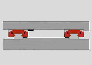
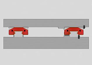
2.5 Installation Methods
The load direction and installation complexity must be considered when choosing a suitable installation method and determining the number and arrangement of the lateral locating surfaces.
Tensile and compressive forces do not have any influence on the lateral locating surfaces. If lateral loads exceeding the permissible lateral force are present, locating surfaces must be provided and lateral fastening points may be necessary. The number and position depend on the actual forces.
The locating surfaces should be arranged according to the force direction of the main load. Lateral locating surfaces should also be provided when vibration and shock loads are present. They also increase the rigidity of the system.
Locating Height and Corner Radii
2 Configuration of the Base Structure
2.5.2 Installation complexity
Locating surfaces simplify installation and reduce the effort necessary for aligning the guide rails. With careful manual alignment of the guideway, lateral locating surfaces are not essential. When deciding on a method, installation complexity should be carefully weighed against design and manufacturing complexity.
2.5.3 Installation options
Shown below are some typical installation methods that differ in terms of the number and orientation of the locating surfaces, the lateral force capacity and the installation complexity. These examples are intended to serve as a design aid.
Installation option 1
No reference surfaces
• The forces are transferred by friction locking
• Long installation time and high engineering expense
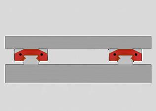
Installation option 2
• Both guide rails with one reference. Carriage side with opposite reference
• Simple installation
• High lateral force absorption from one direction, e.g. for hanging installation
Installation option 3
• A guide rail and carriage with reference and lateral clamping For high lateral forces from both directions (a guide rail with carriage will take the majority of the lateral force) Relatively simple installation
3 Installation and Adjustment Guidelines for the Guideway
3.1 Preparing for Installation
3.1.1 Required tools and equipment
• Fastening screws
• Torque wrench
• ESD protection kit
• Oil stone
• Cleaning materials
3.1.2 Preparing the locating surfaces
• Check locating surfaces of the machine bed and mounting plate for shape and position accuracy
• Clean all locating surfaces thoroughly. Remove ridges and surface irregularities with an oil stone
• Clean the locating and supporting surfaces of the guideways and carriage with a clean cloth
Lightly oil the locating and supporting surfaces
Use white spirit or alcohol for cleaning. Do not use nitro thinner or acetone, since they can damage the measuring system.
Never use compressed air!
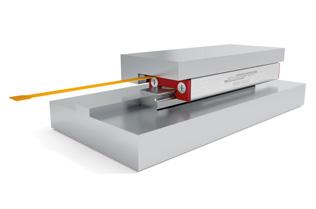
Locating surfaces
A Reference on the mounting plate for the carriage
B Reference on the machine bed for the guideway (both sides of the guideway can be used as locating surfaces)
3.2 Installing the Guideway
• Before installation, the guideway, machine bed, mounting plate and fastening screws must all be at room temperature.
• The MINISCALE PLUS sensor is an electrostatically vulnerable component and is delivered in ESD-protective packaging. To ensure the sensor remains protected, the ESD-protective packaging should not be removed during installation of the MINISCALE PLUS guideway.
• Always tighten the fastening screws with a torque wrench. See section 3.2.1 for tightening torques.
• With relatively long guideways, tighten the fastening screws alternately starting at the middle of the guideway.
• Always brace the locating surface of the guideway against the locating surface of the machine bed. The guideway can be located on both sides, the locating side of the carriage is opposite the carriage side with the company logo/type designation.
The screws can be inserted and tightened through the opening in the carriage.
3.2.1 Tightening torques for the fastening screws
The recommended torque values can be found in the table. These values apply to oiled screws.
The friction coefficient μ can be reduced by up to half when using greases containing MoS2. The corresponding torque values should be reduced by half.
The following table shows the torque values for the fastening screws of strength class 12.9 (friction coefficient 0.125) and of the strength class A2-70 (friction coefficient 0.2) in accordance with DIN 912:
3 Installation
3.3 Cleaning the Dimensional Scale
The dimensional scale of the measuring system is located on the top side of the MINISCALE PLUS guideway. After the guideway has been fixed but before the carriage is mounted, the dimensional scale must be cleaned to ensure it can be read by the sensor. Lubricants, fingerprints and other dirt residue must be removed. A clean, lint-free cloth should be used for cleaning. White spirit or rubbing alcohol are suitable cleaning fluids.Wipe down the dimensional scale on the surface of the guideway with a soaked cloth. Repeat the cleaning several times with a clean cloth for heavy dirt.
The MINISCALE PLUS is lubricated in the factory and supplied ready for installation. No additional lubrication or cleaning is necessary. Do not degrease the tracks during installation.
3.4.1
The relubrication intervals depend on many factors, including the load, operating environment, speed, etc., and therefore cannot be calculated. It is therefore necessary to monitor the lubrication point over a relatively long time.
The initial factory lubrication may be sufficient for several years, depending on the load.
Always use the original type of grease for relubrication. Apply the lubricant to the tracks. Use only small amounts of lubricant, since overlubrication can cause failure of the optical sensors.
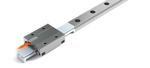
3.5 Mounting and dismounting carriages MINISCALE PLUS onto guideways
Use the included protective plastic rail. This protects the carriage from dirt and prevents it jamming, causing the ball bearings to subsequently escape.
Place the protective plastic rail in line with the guide rail and slide the MINIRAIL or MINISCALE PLUS carriage onto it.
For MINISCALE PLUS carriages, ensure the sensor is over the dimensional scale on the guideway.
3.4 Lubrication
MINISCALE PLUS subsequent lubrication intervals
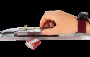
The MINISCALE PLUS optical sensor is an electrostatically vulnerable component and is delivered in ESD-protective packaging. (Electrostatic Discharge).
As soon as it is removed from the protective packaging, MINISCALE PLUS and the interface module of the flexible printed circuit board must be protected against electrostatic fields and discharge. As soon as MINISCALE PLUS is assembled and connected ready for use, it is protected from ESD.
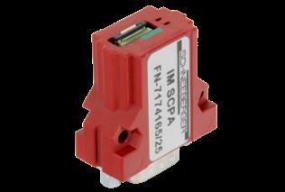
MINISCALE PLUS with ESD Protection
These installation instructions are not a substitute for ESD training. They only provide an overview of how to handle the MINISCALE PLUS.
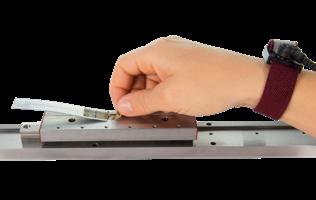
For installation of the MINISCALE PLUS guideways, you need at least one ESD wrist strap with a ground lead or crocodile clip for grounding to the machine bed.
ESD protection and/or a wrist strap is not necessary as long as the MINISCALE PLUS flexible sensor print is in the ESD protective packaging.
4.2 Overview of Relevant Components
4 Installation Guidelines for the Measuring System
4.3 Mating the Interface Module and the Guideway
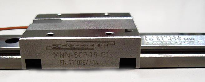
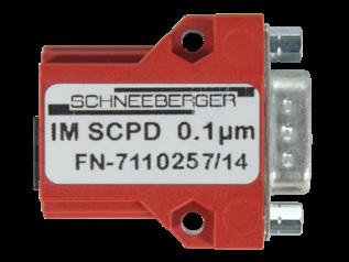
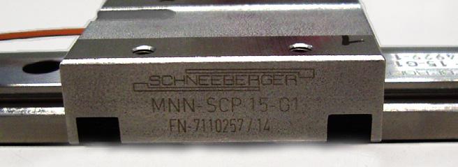
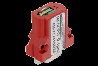
The rails and carriage of the MINISCALE PLUS guideways are labelled with serial numbers. The number is next to the SCHNEEBERGER logo.
The interface modules are configured in factory and matched to the individual MINISCALE PLUS guideways.
Important!
The guideway is supplied as a set or system with the sensor and interface module and must be installed as such.
The carriage serial number is marked on the label of the interface module. This label is attached to the housing or packaging of the interface module.
Serial number on the carriage
Serial number on the rail
The carriage number is printed on the label of the interface module
4.4
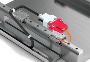
Interface Module Installation Options
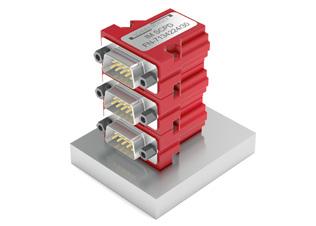
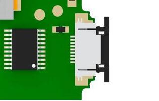
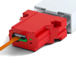
Plugging the interface module into the connecting structure
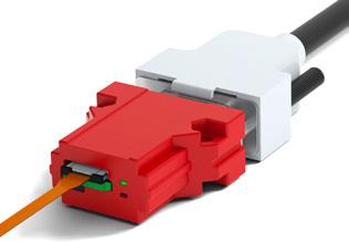
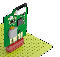
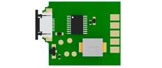
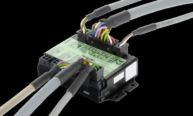
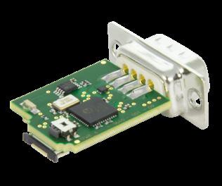
Interface module with housing and D-Sub 9 connector
Advantages:
• Easy screw mounting with M3 screws
• Stackable
Industry standard connector (D-Sub 9) for customer connection
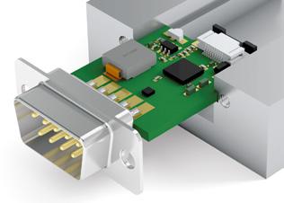
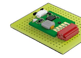
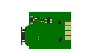
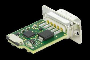
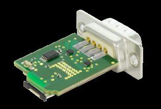
Interface module without housing, with D-Sub 9 connector
Advantages:
• Board can be clamped on the sides or inserted in guides (board edges allow for 1.5 mm insertion depth)
• More compact due to absence of housing
• Industry standard connector (D-Sub 9) for customer connection
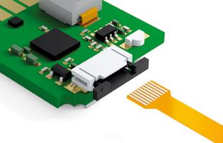
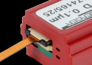
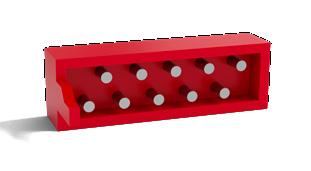
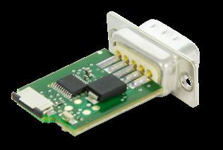
Interface module without housing, with Micro Match connector
Advantages:
• The board can be plugged into customer-provided electronics with a mating Micro Match connector
Note: The board must be additionally secured for protection against vibration.
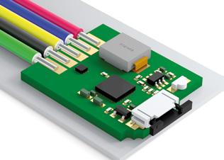
Interface module without housing or connector, with solder terminals
Advantages:
The board can be clamped on the sides, mounted in guides or secured with an electrically insulating adhesive
Less room necessary due to absence of housing and connector
• Cable can be soldered directly
• High flexibility for connection design
Stacked interface modules
The interface module can be mounted on the electronics board vertically or horizontally
Cable soldered directly to the interface module Module attached with silicone adhesive
4.5 Connecting the Flexible Sensor Print to the Interface Module
Always use personal ESD equipment (wrist strap or equivalent) when removing the ESD protection bag
Removing the ESD protective packaging
The ESD-protective packaging should not be removed during installation of the guideway so that the sensor remains protected. The ESD-protective packaging can only be removed once MINISCALE PLUS is grounded on the machine bed and the person is properly protected from ESD (e.g. by wearing an grounded wrist strap).
Remove the glue strip A and the ESD protective packaging B
Be careful to avoid damaging the flexible sensor print C when removing the protective packaging.
Important!
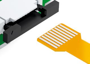
The flexible sensor print is connected to the interface module through a zero insertion force (ZIF) connector.
No force is necessary for insertion. Excessive strain on the ZIF connector can cause the locking mechanism to break. Excessive pressure on the flexible sensor print can cause it to buckle and damage the conducting tracks.
Open the ZIF connector D on the interface module.
To do so, grasp both ends of the black tab E and pull it out 1 mm.
Gently insert the flexible sensor print C approximately 3 mm into the ZIF connector D
Make sure that the contact surfaces of the flexible sensor print are facing upwards (away from the PCB) to make proper contact.
Opening the ZIF connector
The contact surfaces of flexible sensor print must face away from the PCB
4 Installation Guidelines for the Measuring System
3 mm
After inserting the flexible sensor print, lock the ZIF connector again by pushing the black tabs toward the PCB.
Insert the flexible sensor print about 3 mm into the ZIF connector. Then push the tab back again
Important!
The flexible sensor print between the sensor and the interface module may only be used statically. The minimum allowable bending radius of the flexible sensor print is 2 mm.
Forcibly pulling out the flexible sensor print can damage the sensor print. (the ZIF connector retaining force is only a few newtons)
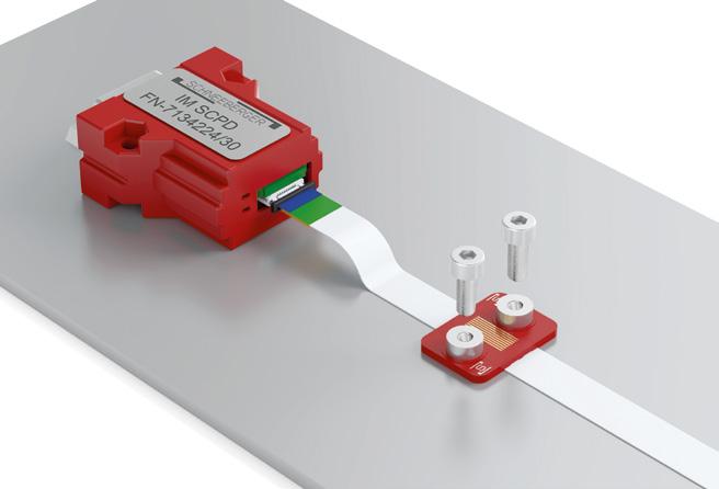
The flat flex cable (FFC) is shielded. The shield consists of a metalized film connected to pin 2 (GND). The extension cable must therefore be connected to the adapter board and the interface module with the right orientation. For this, pay attention to the color coding. The metalized shield is covered by an insulation layer to prevent short circuits with other machine parts.
Correctly inserted sensor print
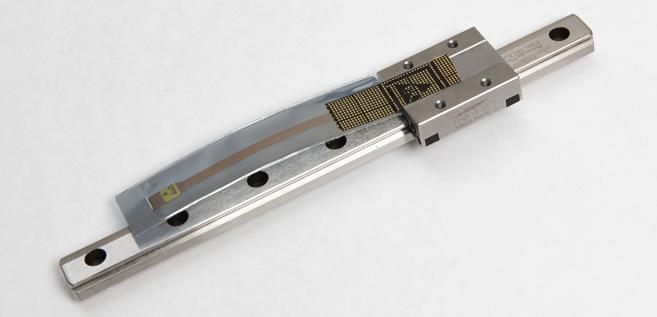
4.6 Extension Installation (FFC Cable)
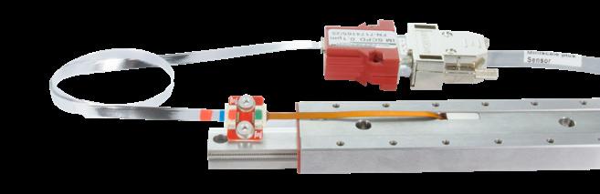
FFC extension cable (top and bottom views)
MINISLIDE MSQscale with FFC extension
4 Installation
Adapter board with flexible sensor print and extension
Adapter board with flexible sensor print and extension
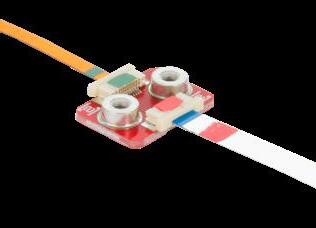
4.6.1 Color coding
To avoid confusion and mistakes when connecting the individual components, they have specific color coding. When connecting the cable, ensure that the same color is visible on the cable end and the connector.
4.6.2 Inserting and locking the cable
When inserting the cable into the ZIF connector, pay attention to the combination of color markings. The green cable end goes to the green ZIF connector. The red cable end goes to the red ZIF connector.
• To unlock the ZIF connector, grasp both ends of the white tab and pull it out 1 mm.
• Gently insert the FFC about 3 mm into the ZIF connector.
• After inserting the flexible sensor print, lock the ZIF connector again by pushing the white tab toward the PCB.
Make sure that the contact surfaces of the flexible sensor print and the FFC are facing downwards (toward the adaptor board) to make proper contact.
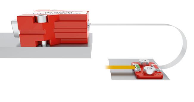
4.6.3 Design notes
Minimum bending radius
The recommended minimum bending radius of the FFC cable for dynamic loads is 10 mm.
Recommended minimum bending radius of the FFC cable for dynamic loads (Example with MINISLIDE MSQscale)
Folding the FFC cable
Single folds in the FFC cable are allowed for cable routing. This allows a large degree of design freedom.
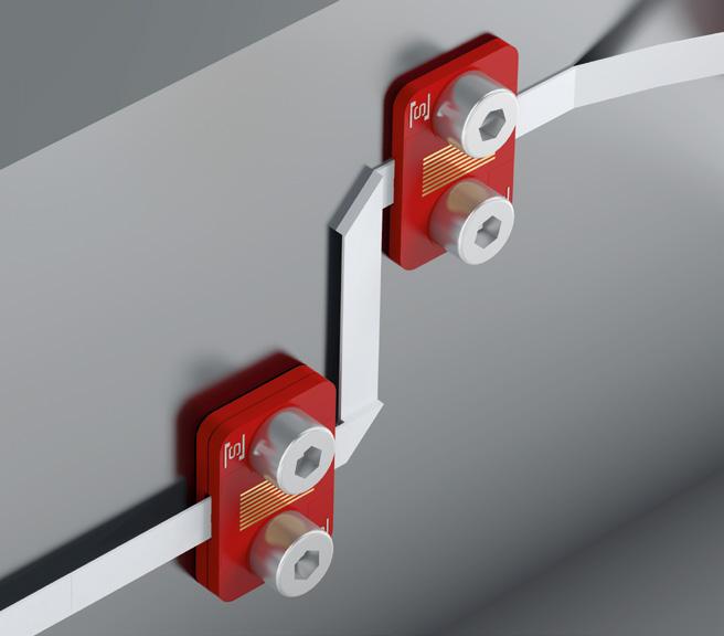
Strain relief
• Rear mounting with an M3 screw threaded into the internal M3 thread of the spacer.
• Front mounting with an M2 screw threaded into an M2 threaded hole in the substructure.
Folded FFC extension cable
Strain relief of FFC extension cable
4.7 Connecting a Customer-provided Cable
If the interface module is not mounted directly on a PCB, it must be connected to the controller by a customer-provided cable.
4.7.1 Recommendations for the customer-provided cable
• In order to ensure maximum resistance to interference, a shielded twisted pair cable is recommended. A cable with additional shielding should be used if necessary.
Suitable shielding must be ensured in any case.
• The cable shielding must not act as a potential equalization conductor.
• Place the encoder cable apart from the power cables and ensure that the two are not parallel.
• If the cable is to be run through a cable carrier, a flexible cable that is suitable for this purpose should be used.
• Keep the cable short (The cable length between the interface module and the controller should not exceed 30 meters).
• The maximum cable length is reduced when increasing speeds in connection with the digital interface module.
• Example: For a maximum speed of 3.2 m/s (digital), the data rate is 8 MHz. This corresponds to a maximum cable length of 15 meters. Maximum cable length with specified output signal frequency
4.7.2 Example cable and connectors for interface module
• Cable: Igus Chainflex, Igus number CF11.02.05.02
• D-Sub 9 socket 9P: Solder terminals: TE Connectivity, TE number 3-1393483-8
• Micro-Match socket 10P:
Straight: TE Connectivity, TE number 8-215079-0 90° angle: TE Connectivity, TE number 8-215460-0
5.1 Signal Transmission
To increase noise immunity, we recommend using differential signals conforming to the RS-422 standard. Balanced signal transmission with opposing signal phases can virtually prevent interference. Virtually all modern drive controllers support this option.
Twisted pairs are used to transmit the signals (A+, B+, R+) and matching inverted signals (A-, B-, R-). At the receiver, the signal is generated by taking the difference between the two signal levels.
With single-ended signal transmission, the signal level changes relative to a reference potential. This type of signal transmission is more susceptible to interference. The signal amplitude in this case is half that of differentially transmitted signals.
Single-ended signals
Differential signals
Reference point
Sine
Cosine
Reference
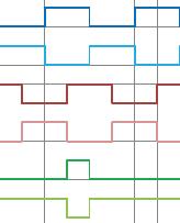
Analog output signals at the interface module. They can be used either single-ended (referenced to ground) or differentially.
Single-ended signals
Differential signals
Digital output signals at the interface module. They can be used either single-ended (referenced to ground) or differentially.
Bus termination resistors for RS 422 should be 120 Ohms.
5.2
Pin Assignments
5.2.1 Analog and digital interface module
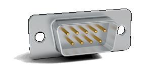
Male 9-pin D-Sub connector or solder terminals:
Image 1: Pin connections of D-Sub 9 connector at the interface module
Male 10-pin Micro Match connector:
5.2.2 Sensor print
Note:
This information is only relevant for customers that process the raw signals directly and therefore do not use the available interface module.
Pin connection of the flexible sensor print
Image 2: Pin connections at the interface module with solder terminals
Pin connections of Micro Match connector at the interface module
Indexpin
Kontakt Nr. 1
5.3 Controller
The MINISCALE PLUS is compatible with every controller that has an incremental encoder port for 1 Vpp signals (analog sine/cosine) or an RS-422 port (digital TTL). The MINISCALE PLUS can be connected to RS-422 or RS-485 encoder inputs.
Suitable modules are available from leading controller manufacturers, including Siemens, Beckhoff, ACS, etc.
For simple applications, a USB counter (for example from Heilig & Schwab; see product catalog Section 5.2) can be used to connect the MINISCALE PLUS directly to a PC.
The maximum input frequency must be considered when selecting a controller. Frequencies up to 8 MHz may occur, depending on the travelling speed and the resolution. See Section 6.4 for some calculated examples.
Settings
For analog signals
The analog signal must be interpolated in the customer-provided equipment in order to obtain the appropriate resolution. The signal period corresponds to a distance of 100 μm.
Example: Signal period 100 μm, interpolation factor 250 and four-edge evaluation yields 0.1 μm resolution. For digital signals
The step size in the drive controller must be configured according to the selected resolution and type of edge evaluation.
The standard resolution of the MINISCALE PLUS is 0.1 μm. A resolution of 1 μm or 10 μm can be ordered as an option.
Most controllers allow selection of the type of edge evaluation. The choices are four-edge, two-edge and single edge evaluation (see Section 6.3).
Controller with encoder port for 1 Vpp signals or quadrature signals
5.3.1
5.4
Function Check
The green LED will light up if the MINISCALE PLUS is correctly supplied with power.
If the carriage is on the guideway and the LED lights up red despite the flexible sensor print being inserted, the error should be found using the table in chapter 9.2 “Error Description”.
LED Supply missing
Supply connected, normal operation
Error condition red does not light up does not light up light up red green does not light up lights up green lights up green
The status of the interface module is shown electronically with the output (“ERR NOT”). ERR NOT is a 5-volt output (TTL level), where a “low - signal” = “pending error” and a “high - signal” = “no error”.
The Error signal should be connected to a high-impedance input. If the input impedance is too low, a current will flow through the red LED and cause it to glow.
Interface module without MINISCALE PLUS flexible sensor print. Both the green and red LEDs light up.
Interface module with correctly connected MINISCALE PLUS flexible sensor print. The green LED lights up.
6 Technical Principles
Max. acceleration
Max. speed
300 m/s2
5 m/s analog, 3.2 m/s digital
Preload classes V1 Preload 0 to 0.03 C (C = dynamic load capacity)
Accuracy classes G1
Materials
- guideways, carriages, ball bearings
- ball recirculation
Areas of application
- temperature range (1)
- vacuum - humidity - cleanroom
Resolution
Accuracy (2)
Repeatability (2)
Dimensional
Supply voltage
Current consumption (typical)
Output signal
Source format
Stainless, through-hardened steel POM
-40 °C to +80 °C (-40 °F to +176 °F)
On request
10 % to 70 % (non-condensing)
Cleanroom class ISO 7 or ISO 6 (in accordance with ISO 14644-1)
(3) (optional: 1 µm / 10 µm)
mm +/- 5 µm (4)
Unidirectional +/- 0.1 µm
Bidirectional +/- 0.2 µm (with resolution of 0.1 µm)
x 10-6K-1
5 V DC +/- 5 %
60 mA (analog) / 90 mA (digital)
Analog: 1 Vpp (at 120 Ω)
Digital: TTL in accordance with RS 422 standard
Differential sin/cos analog signals with reference pulse or
Differential, interpolated digital signals (A, B, R)
The reference signal is synchronised with the incremental signals
(1) The standard lubrication covers a temperature range from -20 °C to +80 °C. Lubricants for other temperatures are available upon request from SCHNEEBERGER.
(2) The values apply to a room temperature of 20 °C (68 °F).
(3) Note the high signal frequencies at high resolution and high speed.
(4) Linearity protocol available on request
6.2 System Accuracy
6.2.1 System accuracy
The system accuracy consists of the long-wave deviation (linearity of the dimensional scale) and the short-wave deviation (e.g. interpolation accuracy) of the scanning system (sensor and interface module). The accuracy values refer to a room temperature of 20 °C (68 °F).
Long-wave deviation
The linearity of the dimensional scale refers to the entire rail length. At this length, the deviation of the dimensional scale is always less than +/- 5 µm at an ideal scale.
Short-wave deviation
All incremental distance measuring systems are influenced by the effects of periodic deviation. This periodic deviation, also called short-wave deviation, occurs due to small deviations in the sensor system or electrical signal processing. This means that the sine and cosine signals deviate from the mathematically exact form. If periodic deviations only occur during digitization and calculation of position, then we talk about an interpolation error.
The short-wave deviation of MINISCALE PLUS is always within a range of +/- 0.6 µm.
6 Technical Principles
The linearity of the dimensional scale is recorded for each system and can be provided to the customer on request. The record always refers to a specific guideway (see the rail number).
Maximum positive and negative long-wave deviation [+/- 3 μm]
Absolute deviation of the dimensional scale
Maximum positive and negative short-wave deviation of the sensor system [+/- 0.6 μm]
The system accuracy is determined by the long-wave deviation and the short-wave deviation
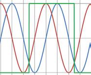
6.3 Interpolation
For distance measuring applications, interpolation means the signal conversion of analog input signals into digital output signals with a smaller signal period. This is necessary as counter readings and/or position readings cannot be generated directly from analog signals.
The interpolation factor defines the ratio of signal periods from the analog input signal to the digital output signal.
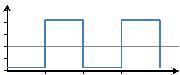
The output of the interpolation process is a quadrature signal, which means two pulse waveforms with a 90° phase offset. The resolution is defined by the distance between two edges of the quadrature signal.
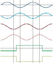
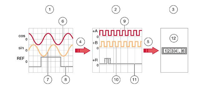
The analog input signals (sin, cos, REF) are interpolated (red arrow) to digital output signals (+A, +B, +R). Inverted signals are not represented:
1. Analog input signal: sin, cos, REF
2. Digital output signal: +A, +B, +Z
3. (Downstream electronics)
4. Interpolation
5. Signaling
6. Analog input signal (cos)
7. Analog input signal (sin)
8. Analog input signal (REF)
9. Digital output signal (+A)
10. Digital output signal (+B)
11. Digital output signal (+Z)
12. Measuring counter, PC, controller for machine etc.
6.4
Evaluation of Digital Signals
The digital signals, consisting of the two incremental signals A and B and the reference signal R, are transmitted to the downstream electronics. This can be a simple display unit, a PC or a machine controller.
The downstream electronics determines the position value from the digital signals by counting the signal edges. The counting direction is determined from the phase relationship of the signals A and B. Depending on how many edges are being evaluated, we talk about:
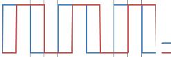
1. Single edge evaluation
Only one edge is counted per channel. One measuring step will therefore correspond to one digital signal period.
2. Two-edge evaluation
Both rising and falling edges of a channel are counted. One measuring step will therefore correspond to half the digital signal period.
3. Four-edge evaluation
Both rising and falling edges of both channels are counted. One measuring step will therefore correspond to a quarter of the digital signal period.
1. Single edge evaluation
2. Two-edge evaluation
3. Four-edge evaluation
4. In each case one measuring step
5. Resolution
6. Digital signal period
6.4.1 Resolution
The resolution is the smallest measurable change in position of the measuring system. This corresponds to the distance between two edges of the quadrature signal. The resolution is determined by the period of the analog signal, the interpolation factor and the evaluation method.
Example of resolution calculation (A)
I Interpolation factor (default)
P Period of the input signal
250
100 μm
E Evaluation (4 edges) factor = 4
6.5 Signal Frequency
The signal frequency at the interface module output depends on the travelling speed and the resolution (digital module) or the increment of the dimensional scale (analog module). To ensure that no steps are lost, the maximum input frequency of the controller must be greater than the calculated maximum output frequency of the interface module.
f = Frequency in Hz
v = Speed in m/s
P = Increment in m ƒ = v p
6.5.1 Example of calculation for analog MINISCALE PLUS
v travelling speed 2 m/s
P signal period (corresponds to the increment of the dimensional scale) 100 µm
f Frequency
ƒ = v = 2 m/s = 20´000 Hz = 20 kHz p 100*10-6 m
6.5.2 Example of calculation for digital MINISCALE PLUS
The maximum output frequency of the digital interface module is 8 MHz per channel. This means that the A signal and B signal can each have a maximum frequency of 8 MHz. With Four-edge evaluation of the A/B signals, the counting rate is 32 MHz, corresponding to a maximum speed of 3.2 m/s with a resolution of 0.1 μm.
Maximum performance of digital MINISCALE PLUS
v max. speed
A Resolution
3.2 m/s
0.1 µm
P Digital signal period (4 x resolution) 0.4 µm
Calculation of the maximum output frequency of the interface module, which corresponds to the minimum required input frequency range of the controller:
ƒ = v 3.2 m/s = 8´000´000 Hz = 8 MHz p 0.4*10-6 m
Calculation of the minimum required controller counting frequency (with 4-edge evaluation):
ƒ = v 3.2 m/s = 32´000´000 Hz = 32 MHz p 0.1*10-6 m
Example speed v
In the opposite direction, the speed or resolution can be calculated from a given frequency (for example, limited by the selected controller).
f max. controller input frequency 1 MHz
A Resolution
0.1 µm
P Digital signal period (4 x resolution) 0.4 µm
In the interface module, the sensor data is converted into standardized analog signals (1 Vpp) or standardized digital signals (TTL).
• The signals are amplified
• Phase errors between the sine and cosine signals are corrected
• The offset is compensated
The digital interface module also includes an interpolator that converts the analog signals into digital signals. For more information, see Section 6.2, “Interpolation”. Digital Analog Designation D A
• Signal processing close to sensor provides better noise immunity
Advantages
Disadvantages
• No additional interpolation necessary
Can be realigned at the customer site
• Very high frequencies at high speeds and high resolution
• Customer can independently choose the interpolation factor
• Lower frequencies
• Faster travelling speed possible
• Realignment at the customer site is not possible, which means that the entire system (guideway and interface module) must be replaced in the event of a defect
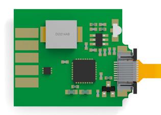
Digital, with housing
Top view: Digital, without housing
Bottom view: Digital, without housing
Analog, with housing
7.1 Interface Module
7.1.1 Comparison of analog and digital interface modules
7.2 Accuracy Class
7.3 Repeatability
The accuracy class specifies the maximum expected measuring deviation of a system under the specified operating conditions. A distance measuring system with an accuracy class of 3 µm allows deviations of +/- 3 µm.
Unidirectional repeatability of a measuring system is generally understood to mean the ability to repeat the results that a particular system returns under exactly the same environmental conditions. In assessing this, the measuring deviation must be known and be factored into the analysis.
The repeatability of an axis position can be determined for a specific travelling speed using simple methods by calculating the arithmetic mean and the standard deviation of many measurements.
7.4 Referencing
Incremental measuring systems cannot determine the exact position after being switched on. For this reason, another track is added alongside the incremental track; the reference track. One or multiple reference points can be marked on the reference track.
A reference run of the carriage is required to reference the system. The axis usually travels in one direction until a mechanical stop. From there, the axis travels backwards until the reference mark is covered. Usually, the equidistant reference mark is always approached from the same direction. (unidirectional)
The controller can then modify the internal counter to a specified value using the reference signal. For the analog interface module, the controller recognizes a predefined position for the incremental signals (this is usually SIN = COS and both greater than zero), as well as REF = “high” as the reference position.
7.5 Periodic Deviations
All incremental distance measuring systems are influenced by the effects of periodic deviation, whose wave length corresponds exactly to the graduation spacing or a fraction of it. This periodic deviation, also called short-wave deviation (SWD), occurs due to small deviations in the sensor system or electrical signal processing. This means that the sine and cosine signals deviate from the mathematically exact form. Deviations can be classified depending on the arrangement (harmonics).
SWD period Deviation occurs due to 1 signal period
Sine/cosine offset 1/2 signal period Sine and cosine amplitude are different 1/3 – 1/8 signal period
Sensors deliver a signal which is fundamentally different from the sine wave shape
7.5.1 Interpolation Errors
If periodic deviations only occur during digitization and calculation of position, then we talk about an interpolation error.
7.6
Comparator Errors
7.7
Sampling Rate
7.8
Single-Ended Signaling
The comparator error, also referred to as the Abbe error, is a systematic deviation which occurs when the axis of the length standards do not coincide with the axis of the distance standards. The causes for the deviation are minute rotary movements in the axis design, which influence the measuring result.
The sampling rate describes the frequency at which the analog signal is sampled per time interval. Usually the time interval is one second, which is why the unit for the sampling rate is Hz. In order to guarantee a complete reproduction of the original signal, the sampling frequency should be at least twice that of the original signal in accordance with the Nyquist–Shannon sampling theorem.
7.9
Differential Signaling
For single-ended signaling, the voltages change relative to a reference potential (electrical ground). This is a simple and convenient way of transferring data, requiring just one wire per signal.
The disadvantage is the relatively high susceptibility to interference. This type of signaling should therefore only be used for short distances and low speeds.
7.10
Direction of Travel
For differential signaling, the signals are described by a voltage difference without reference to electrical ground. Instead of a single signal conductor, a pair of wires is used. One wire carries the signal, and the other carries its inverse. The controller then composes the difference between the two signals into the so-called difference signal. (e.g. the A + and A - signals become A).
Differential signaling is the better solution for most applications as it is more tolerant to interference. Couplings to the signals are almost identical for both wires such that interference is almost eliminated when generating a difference.
The RS422 standard (differential) was specifically developed for larger distances and higher transfer rates.
The direction of travel can be read from the phase relationship of the electrical signals. One signal either leads or lags the other, depending on the direction.
With the digital interface module:
If the carriage moves in the direction of the flexprint, the signal on channel A is 90° ahead of channel B. From this the controller recognizes a positive direction of travel, meaning that the counter counts upwards. In the other direction, the signal on channel A is 90° behind channel B. The counter counts downwards.
The counting direction for the analog interface module is reversed.
8 Application Tips
The MINISCALE PLUS has an open optical measuring system. As with every optical measuring system, contaminants such as dirt impair the operation of the system. It is therefore not recommended to use the MINISCALE PLUS in applications where dust, chips, particles or liquids are expected to be present during the process operation. Large scratches or other types of damage to the dimensional scale are equally harmful.
Generally speaking, the MINISCALE PLUS is most suitable for use in clean environments. Typically in situations where other optical devices are used or where a clean environment is present.
In this regard, the MINISCALE PLUS differs from the AMS distance measuring systems, which are specifically designed for harsher environments.
The MINISCALE PLUS and its accessories have been tested according to the EN 61000 standard. The test results confirm that the MINISCALE PLUS complies with the requirements of the standard. However, this does not eliminate the possibility of unwanted electromagnetic interference in specific application cases. Compliance with relevant EMC design practice is always necessary.
Static magnetic fields have no effect on the MINISCALE PLUS. Induction effects may occur with alternating fields, depending on the cable layout.
9 Troubleshooting
Alignment is only necessary for a subsequent delivery of the digital interface module! Calibration by the customer is not possible for the analog interface module.
Procedure:
• Switch on MINISCALE PLUS Press and hold the alignment button A
• Move the guideway slowly along the entire stroke length (4 – 5 times) Release the alignment button
• Reset MINISCALE PLUS (= switch it off and on again)
• Drive the guideway along the entire stroke length and make sure that only the green LED lights up
• If the red LED lights up, the adjustment procedure must be repeated
Interface module with housing A Alignment button
Interface module without housing A Alignment button
9.1 Aligning the Digital Interface Module
9 Troubleshooting
9.2 Error Description
Error
Green LED on interface module not lit
Possible cause
No supply voltage or incorrect supply voltage at interface module
Incorrect pin assignment of customer-provided cable
D-Sub 9 or Micro Match connector not properly connected
The MINISCALE PLUS has been damaged by improper handling (not in compliance with ESD requirements)
Incorrect supply voltage on interface module
Flexible sensor print not connected to interface module
Flexible sensor print not correctly connected to interface module. The contact surface of the flexible sensor print is turned 180°.
The flexible sensor print is not fully inserted in the ZIF connector
Solution
Check supply voltage (+5V DC)
Check pin assignment
Check connection
Replace the MINISCALE PLUS
Check supply voltage (+5V DC)
Connect the flexible sensor print
Turn the flexible sensor print by 180°
Check connection
Red LED on interface module lights up
Red LED glows slightly
The flexible sensor print is damaged or kinked (for example, hairline cracks in the contacts)
The MINISCALE PLUS has been damaged by improper handling (not in compliance with ESD requirements)
Sensor input signals outside normal range, for example due to dirty dimensional scale
"ERR NOT" output connected to a low-impedance input, allowing a small current to flow through the LED.
Replace the MINISCALE PLUS
Replace the MINISCALE PLUS
Clean and coat the dimensional scale as described in Section 3.3
Realignment is possible with a digital system (see Section 9.1)
Connect the "ERR NOT" output to a high-impedance input or ignore the glowing LED
Error
Position information does not match travel distance
Possible cause Solution
Maximum input frequency of customer's controller exceeded
Resolution set incorrectly in customer's controller
Edge evaluation factor too low
Electromagnetic interference
The flexible sensor print is damaged or kinked (for example, hairline cracks in the contacts)
Dimensional scale is very dirty
Maximum speed of 3.2 m/s exceeded (with 0.1 µm resolution)
Reduce travelling speed or resolution
Adjust settings in customer's controller
Set X4 edge evaluation in customer's controller
Take EMC protective measures: Use shielded cable with twisted-pair conductors, route motor cables and control cables separately, etc.
Replace the MINISCALE PLUS
Clean and coat dimensional scale as described in Section 3.3; replace system if necessary
Limit the speed to 3.2 m/s or reduce the resolution
Check matching of interface module and guideway
Malfunction in digital interface module
Malfunction in analog interface module
The number on the interface module does not match the MINISCALE PLUS carriage number
Reference mark not detected
Incorrect position indication with Heilig & Schwab USB counter
The number on the interface module does not match the MINISCALE PLUS carriage number
Reference mark not passed
Guideway is dirty
Analog: The interpolator has a fixed interpolation factor of 256, resulting in a resolution of 0.39 µm
The maximum input frequency of the digital input is 500 kHz, so with a resolution of 0.1 µm, the speed is limited to 0.2 m/s (counter 026) or 0.4 m/s (counter 046)
Perform alignment as described in Section 9.1
Return system to SCHNEEBERGER
Check matching of interface module and guideway
Return system to SCHNEEBERGER for alignment
Adjust travel distance
Clean and coat the dimensional scale as described in Section 3.3
Return system to SCHNEEBERGER
Calculate with corresponding resolution
Reduce speed or resolution
Other error
Further investigation needed
Contact SCHNEEBERGER
SCHNEEBERGER COMPANIES
SWITZERLAND SCHNEEBERGER AG
Lineartechnik St. Urbanstrasse 12 4914 Roggwil/BE
+41 62 918 41 11
+41 62 918 41 00 info-ch@schneeberger.com
CHINA SCHNEEBERGER Precision Motion System Asia Pacific 1/F, F Building, Hongfa Science Park, Tangtou Community, Shiyan Street, Boan District, Shenzhen, P.R.C 518108
MINI-X MINIRAIL / MINISCALE PLUS / MINISLIDE MONORAIL and AMS profiled linear guideways with integrated measuring system MONORAIL and AMS application catalog POSITIONING SYSTEMS
A.MANNESMANN A member of SCHNEEBERGER linear technology