You can always find the latest version of our catalogs in the Download area of our website.
Disclaimer
This publication has been compiled with great care and all information has been checked for accuracy. However, we can assume no liability for incorrect or incomplete information. We reserve the right to make changes to the information and technical data as a result of enhancements to our products. Reprinting or reproducing, even in part, is not permitted without our written consent.
7.2.4
7.2.5
Installation and Adjustment Guidelines for
In 1923, SCHNEEBERGER laid the foundations for the global linear motion technology of today. SCHNEEBERGER innovation made it possible to produce linear guideways, which in terms of load capacity, reliability and cost-effectiveness became what is today the definitive industry standard.
The same principles that resulted in our success still apply today: the spirit of innovation, a no-compromise approach to quality and the ambition to deliver products to our customers that are always technically and economically superior. Both then and now the name SCHNEEBERGER is synonymous with innovative linear motion technology and cost-effective solutions throughout the world. Our development, production and application expertise have given us a reputation as a well-respected business partner. Together with our committed, customer-oriented employees, we are global leaders.
We have developed broad and extensive technological skills from many successful projects in a variety of industries. Together with customers we evaluate the best products from the standard range or define project-specific solutions. Thanks to many years of experience and consistent focus on linear motion technology, we have been able to continuously develop our products and solutions so as to provide our customers with technical advantages.
State-of-the-art production technologies and highly skilled employees at our production facilities produce to the highest quality standards. We are pleased to present our high-precision MINI-X series products in this catalogue. MINI-X includes MINIRAIL, MINISCALE PLUS, and MINISLIDE product lines which are suitable for use in a wide range of applications:
• Biotechnology
• Semiconductor Industry
• Laboratory Automation
• Medical Technology
• Handling and Robotics
• Pick-and-place Machines
• Metrology
• Micro-automation
• Nanotechnology
• Optics Industry
• Processing Machines for Microtechnology
MINI-X enables economical, zero backlash guide systems to be constructed with ease. MINI-X boasts the following outstanding product characteristics:
• High level of smoothness and consistent accuracy
• No stick-slip effect
• High speed and acceleration
• Minimal wear
• High level of strength
• High rigidity
• High load-bearing capacity
• Robustness
• Suitable for use in a vacuum or cleanroom
Our skilled and committed employees are pleased to offer product recommendations to assist in optimising your application designs.
SCHNEEBERGER - «Essentials for the Best»
2 Useful Guidelines
2.1 Videos
2.2 2D and 3D Drawings
Videos about MINI-X (MINIRAIL, MINISCALE PLUS and MINISLIDE) are available on our website www.schneeberger.com under the respective product group.
Drawings and models are available on the Cadenas Part Server free of charge in all formats.
Additional product information is available from the download section of our website www.schneeberger.com.
2.3 Regulations Regarding Substances and Limit Values
SCHNEEBERGER AG linear engineering abides by legal requirements in its product design and production. The products in this catalogue therefore meet the requirements laid out by RoHs and REACH. Compliance with specific requirements can be confirmed upon request.
Cadenas Part Server
Useful Guidelines
2.4 Index and Type Designations Assigned to Chapters
Useful Guidelines
Useful Guidelines
Useful Guidelines
2.5 Unit Names
Name Description
Event probability
Dynamic load capacity (≙ C100)
Static load capacity
C100 Dynamic load capacity for a 100,000 m travel distance
C50 Dynamic load capacity for a 50,000 m travel distance
Ceff Effective load carrying capacity per rolling element
fK Contact factor
H Stroke
K Spacing between two carriages
L Length
L Nominal service life
L1 ... L2 Partial lengths
Lb Carriage spacing
Lh Nominal service life
M Moment load longitudinally and laterally Nm
Mds Tightening torque Ncm
ML Permissible moment load longitudinally and laterally Nm
MOL Permissible longitudinal static torque Nm
MOQ Permissible lateral static torque Nm
MQ Permissible lateral moment load Nm
n Stroke frequency min-1
P Dynamically equivalent load N
Q Spacing of the guide rails mm
Vm Medium travelling speed m/min
Vvsp Preload factor
MINI-X embodies the newest generation of miniature guideways for demanding applications. They are extremely robust and prove themselves in every application with their high level of smoothness, precision and reliability.
MINIRAIL – The miniature profiled linear guideway
• Process reliability thanks to superior design
• Speeds up to 5 m/s and acceleration up to 300 m/s2
• The precisely finished carriages can be interchanged as desired
• Low risk of contamination thanks to tight clearance between the carriage and guideway
• Low travel pulsation thanks to optimally shaped ball recirculation
• Vacuum-compatible down to 10-7 mbar (10-9 mbar on request)
• The long-term lubrication LUBE-S option enables maintenance-free operation
• Unlimited rail length
MINISCALE PLUS – Guiding and measuring in one
• Due to the fact that the measuring system requires very little space, very compact designs can be implemented
• Simple installation since the distance measurement does not need calibration
• Additional components and their installation are not necessary
• Optimal thermal connection to the machine bed
• Global drive compatibility
MINISLIDE MS – Maximum performance, minimum space
• The Gothic arc profile of the guideways allows for load capacities which are up to 15 times higher than that of a 90° V-profile
• MINISLIDE MS enables compact and robust constructions with minimal weight
• The material used and the outstanding design allow for a high level of rigidity
• Vacuum-compatible down to 10-7 mbar
• Cage centring system
MINISLIDE MSQ – Productivity encapsulated
• Maximum process reliability thanks to integrated cage control
• The snug, two-row profile of the guideways allows high load capacities, and because of the materials used, unrivalled rigidity
• MINISLIDE MSQ enables compact and robust constructions with minimal weight
• Vacuum-compatible down to 10-9 mbar
MINIRAIL
MINISCALE PLUS
MINISLIDE MS
MINISLIDE MSQ
4 Applications
MINI-X is used in situations where high precision and process reliability are needed due to constricted space. The unique advantages of MINI-X come into their own in the following applications:
• Processing machines for the micro-sector
• Biotechnology
• Semiconductor industry
• Laboratory automation
• Medical technology
• Metrology
• Micro-automation
• Nanotechnology
• Optics industry
• Robotics
Modern microscopes are indispensable in research and in day-to-day medical processes. In order to analyze the samples quickly and accurately, the slide underneath the lens has always been moved by means of a cross table.
The Scan table shown is based on MINIRAIL and MINISCALE PLUS; the drive is provided by linear motors. Using these compact components reduces the weight compared with conventional constructions (ball screws and multiphase motors) by a factor of around five. The scan table is not only fast but also decidedly quiet. Precision in the smallest area - reproducible with an accuracy of several microns.
Microscope with scan table
Scan table
4 Applications
Use of MINISLIDE
The precision and speed of flying probe testers are extremely important for the electrical testing of structures measuring just 50 µm or less. The high acceleration in particular must not affect the contact accuracy of the test design.
The manufacturer offers different machine configurations for a wide range of products. An extremely wide range of materials and designs, including rigid and flexible PCBs and everything from IC packages to touch panels, can be tested with the latest machine generation.
Acceleration: 30 g
Working stroke: 1 – 2 mm
Total stroke: 10 – 15 mm
Reproducibility: 1 – 2 µm at the point of work
Lubrication: Maintenance-free after initial lubrication
The flying probe test system
Test head with modified MINISLIDE MSQ 7 40.32
5 Customized Solutions
SCHNEEBERGER’s many years of experience in linear motion technology have influenced the concept and design of MINI-X. Due to their outstanding performance parameters, MINI-X plays a decisive role in the accuracy of every application.
MINI-X are universally applicable. SCHNEEBERGER offers configurations upon request for application-specific requirements, including:
• Defined push forces
• Application-specific lubrication
• Special packaging
• Hybrid guideways with ceramic ball bearings
• Coatings for dry runs
• Customer-specific design
• Defined cage reset force
• Defined records
Examples of customer-specific MINI-X products
MINIRAIL with vented holes in carriages and guideways, vacuum-packed for use in cleanrooms.
MINISLIDE MSQ finished specifically to the customer’s needs.
MINISLIDE MS with ceramic ball bearings, additional holes and positioning pins. Push and cage reset forces are defined and recorded.
Installation in SCHNEEBERGER’s cleanroom
MINIRAIL modified according to the requirements of the customer
MINISLIDE MSQ finished according to the requirements of the customer
MINISLIDE MS modified and specified according to the requirements of the customer
6 Special Requirements
6.1 Temperature Range
MINI-X can be operated in different temperature ranges. SCHNEEBERGER can deliver guideways with application-specific lubricants on request.
on request)
6.2 Speeds and Acceleration
MINI-X are equipped for the following speeds and acceleration:
6.3 Cleanroom
In the cleanroom, it is necessary to reduce the number of particles as well as apply appropriate types of lubricating grease. SCHNEEBERGER delivers guideways for cleanroom classes up to ISO 6 on request. The guideways are packaged appropriately and lubricated according to requirements.
6.4 Vacuum
Corrosion resistant guideways are preferred for use in a vacuum. It is also necessary to avoid out-gassing of plastics, to ensure vented of attachment holes and to use an appropriate lubricant.
On request, SCHNEEBERGER can deliver the guideways packaged in a cleanroom and lubricated according to requirements.
Vacuum ranges for standard MINI-X products: MINIRAIL
mbar (HV). 10-9 mbar (UHV) on request. The values apply without wipers
Notes: the suitability for a vacuum depends on the materials used.
Special Requirements
6.5 Corrosion Resistance
6.6 Short Strokes
Corrosion protection is not just required in a cleanroom or vacuum. Medical, laboratory or food applications demand corrosion-resistant steel, as used in all MINI-X products.
The effects of short strokes include point compression along the tracks and inadequate lubrication. As a result, short strokes reduce the service life of the guideway. This can only be reliably determined by means of experimentation.
6.6.1 Short Strokes with MINISLIDE
The stroke length of the guideway is so low that the rolling elements cannot pass the position of the next rolling element. As a result, local wear marks form on the tracks. Overstraining the tracks with short strokes leads to material damage which inevitably leads to the loss of preload. The accuracy of the guideway can consequently be reduced which can lead to premature failure.
Additionally, high-frequency strokes can break the lubricating film, further exacerbating wear. With suitable lubricants and regular strokes along the entire stroke length, better lubrication can be achieved, delaying the effects of material wear.
6.6.2
Short Strokes with MINIRAIL and MINISCALE PLUS
In the starting position (1), only the ball bearings directly under load are lubricated. Once the carriage moves to the right (2), a section of the ball bearings takes up the lubricant via the guideway. Only once position 3 has been reached will all of the ball bearings and all four corners of the ball recirculation be lubricated.
A short stroke is when the stroke of the carriage corresponds to less than twice its length. This can lead to damage, particularly in the redirection unit. Regular lubricating strokes along the entire stroke length at a minimum of twice the length of the carriage ensure better lubricant distribution, protecting the guideway from premature wear.
We recommend using LUBE-S long-term lubrication for short strokes. (see chapter 8.1).
Stroke movement of the ball bearings Wear marks and broken lubricating film
MINIRAIL Product Overview
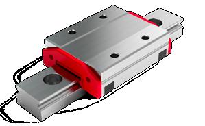
MINIRAIL are highly accurate miniature profiled linear guideways with ball bearings. Their precision, robustness, innovative design and strength are second to none.
The range includes the standard rail widths of 7, 9, 12 and 15 as well as wider widths of 14, 18, 24 and 42. The carriages are available in four lengths: MNNS (short), MNN (standard), MNNL (long) and MNNXL (extra long).
The MINIRAIL range
7.1 Product Characteristics
7.1.1
Carriage Interchangeability
Because the carriages are made to precisely the same size, they can be switched for other carriages at will (carriage uniformity system). This simplifies storage and maintenance considerably.
Note:
The MINISCALE PLUS carriages and guideways are always matched to each other and are therefore delivered as a set (carriage mounted on rails) - (see chapter 18.1).
7.1.2 LUBE-S Long-term Lubrication from SCHNEEBERGER
The SCHNEEBERGER solution for long-term lubrication LUBE-S is described in detail in chapter 8.1. LUBE-S enables maintenance-free operation for up to 20,000 km, requires no extra space and is good for the environment and short stroke applications.
Note:
Guarantee only with lubricants tested and approved by SCHNEEBERGER.
7.1.3 The Carriage Range
The different carriage lengths from short to extra long, along with the corresponding load capacities, allow greater flexibility when designing axes of motion.
LUBE-S
Standard => MNN
Short => MNNS
Extra long => MNNXL
Long => MNNL
Carriage uniformity system
LUBE-S long-term lubrication
MINIRAIL carriage range
Made of corrosion-resistant, through-hardened steel
7.1.4 Speed and Acceleration
The innovative embedding of ball recirculation in the carriage allows speeds of up to 5 m/s and accelerations of up to 300 m/s2
7.1.5 High Load Capacities
The Gothic arc profile of the guideway tracks allows high load capacities.
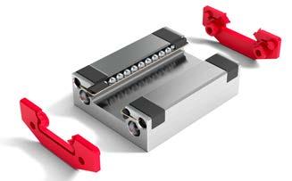
7.1.6 Simple Installation and Maintenance
Whether a carriage is moving along the guideways or being prepared for installation, the ball bearings are always held in place by a retaining wire. This makes for easier handling and is a prerequisite for simple installation and replacement carriages.
7.1.7
Exceptional Robustness
Carriages and guideways are made of through-hardened stainless steel. They are therefore superbly suited for use in the most demanding of applications.
Enlargement of ball recirculation in the carriages
Gothic arc profile of the guideway tracks
Retaining wire holding the balls in place
7.1.8
Sophisticated Lubrication Concept
MINIRAIL are delivered unlubricated as standard, allowing you to decide on the optimal lubrication for the respective application (see chapter 7.2.12 «Lubricating MINIRAIL»).
Each wiper on the carriages features two lubrication holes so that the left and right ball recirculation pathways can be lubricated with oil separately. This ensures that the tracks of the carriage can be supplied with lubricant independent of their installation orientation.
Also consider the long-term lubrication option LUBE-S in chapter 8.1.
7.1.9
Excellent Running Properties
The ball recirculation, transitions and run-ins on the carriages are designed for consistent redirection of the ball bearings. They ensure optimal containment of the enormous centrifugal forces involved with minimal friction.
7.1.10 Maximum Protection from Contamination
The ultra-precise manufacturing of the carriages and guideways ensures minimal clearance between them. This prevents the migration of dirt particles into carriages.
MINIRAIL lubrication with oil
Polished run-ins
Small clearances between carriages and guideways
The carriages are fitted with profiled wipers as standard. They are snap-fitted into place and can therefore be easily replaced. Alternative variants (for example low-friction or clearance wipers) are described in chapter 9.2.
In order to prevent the accumulation of dirt, the attachment holes in the guideways can be sealed with plastic plugs (see chapter 9.1).
Detachable wipers
Plastic plugs for sealing
7 MINIRAIL Product Overview
7.2 Technical Information and Alternative Variants
7.2.1 MINIRAIL Performance Parameters
Max. acceleration
300 m/s2
Max. speed 5 m/s
Preload classes V0 slightly play up to 0.01 C (C = dynamic load capacity) V1 Preload 0 to 0.03 C (C = dynamic load capacity)
- temperature range (1) -40 °C to +80 °C (-40 °F to +176 °F)
- vacuum (2) vacuum (max. 10-7 mbar)
- humidity 10 % – 70 % (non-condensing)
- cleanroom
Cleanroom class ISO 7 or ISO 6 (in accordance with ISO 14644-1)
(1) Depending on the load, temperatures of up to +150 °C (+302 °F) are possible with modified ball recirculation made of PEEK (on request). The standard lubricant covers a temperature range from -20 °C to +100 °C. SCHNEEBERGER also accepts requests for lubricants for other temperatures.
(2) For use in high vacuum, the wipers on the carriages must be removed. MINIRAIL with modified ball recirculation made of PEEK can also be operated in a vacuum (up to 10 -9 mbar) on request. Use in a vacuum requires a special lubricant available from SCHNEEBERGER. So that no air remains trapped in the blind holes, the fastening screws must be vented.
7.2.2 Reference and Supporting Surfaces
The reference and supporting surfaces of carriages and guideways are designated as follows.
Standard sizes 7, 9, 12 and 15 Wider widths 14, 18, 24 and 42
Carriage reference and supporting surfaces
Guideway reference and supporting surfaces
The polished reference side of the carriage is opposite the carriage side with the company logo / type designation. Either side of the guideway can be used as a reference side.
Logo side
Logo side
7.2.3 Accuracy Classes
MINIRAIL carriages and guide rails are made to a high precision independently of each other. The carriages are interchangeable. This means that any carriage of the same size and accuracy class can be used on the guide rails without influencing the preload class.
MINISCALE PLUS carriages and guide rails are also made to a high precision. Due to the integrated linear encoder, the carriage and guideway are matched together and therefore can only be changed as a set.
Both G1 and G3 accuracy classes offer a precise MINIRAIL range suited to the application-specific needs of the customer. The accuracy classes determine the size tolerances and the running accuracy of the carriages on the guideways:
High accuracy G1
Standard accuracy G3
Note:
MINIRAIL are available in accuracy classes G1 and G3 MINISCALE PLUS are always delivered in accuracy class G1.
Tolerances
Accuracy class G1 +/- 10 µm
G3 +/- 20 µm
Measured relative to carriage centre Difference in measurement between several carriages on the same position on the rails
For the measurements mentioned above, the guideway is mounted on a flat surface. Measurement is taken from the middle of the carriage. Since the measurement is stable, it is based on the midpoint of the two supporting surfaces Marked side
Reference side
7.2.4 Running Accuracy
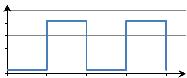
In terms of tolerances, the running of the carriage on a guideway can take on either a linear or wave-like shape. The maximum permissible deviation is limited by the accuracy class of the guideway. As shown on the following diagram, the tolerance is determined by the rail length and by accuracy class G1 or G3.
Rail length (mm)
Example according to the diagram:
A rail length of 600 mm and accuracy class G1 results in a maximum permissible deviation of 4.0 µm
The parallelism deviations result from the manufacturing tolerances of the guide rails. The upper diagram shows the maximum parallelism deviation ∆ (µm) in operation, depending on the guide rail length. A prerequisite for validity is an ideal installation of the respective guideway.
7.2.5 Preload Classes
The preload classes are defined as a fraction of the dynamic load capacity C (see chapter 17). The amount of preload is generally based on the intended use of the guideways.
An increased preload … … increases the rigidity … increases the displacement resistance … reduces the service life
Preload class Preload corresponding accuracy class V0 slightly play up to 0.01 • C G3 V1 0 to 0.03 • C G1 or G3 Running accuracy ∆ (μm)
7.2.6 Push Force
The push force of the carriage is influenced by the preload class, the lubricant and the wipers used.
The carriages can be delivered with a defined push force on request (see chapter 8.3).
7.2.7 Friction and Smoothness
SCHNEEBERGER places high emphasis on running smoothness during the manufacturing process. Transitions, run-ins and run-outs and the quality of the plastics are given top priority. This also applies in respect of the rolling elements used, which must satisfy the most stringent quality demands. Under normal operating conditions, a coefficient of friction of 0.005 can be expected (without wipers).
7.2.8 Carriage Uniformity System
The MINIRAIL carriages are interchangeable within preload and accuracy classes. With this in mind, guideways and carriages are packaged separately (see chapter 18.1). This simplifies interchangeability and storage.
7.2.9 Rail Length and Hole Spacings
L3 = standard rail lengths in mm
L4, L5, L10 = standard hole spacings in mm
Calculating rail lengths that do not correspond to the standard
Individual rail lengths can be calculated with the following formula (up to a maximum rail length according to the above table):
L 3 = (n-1) • L4 + L 5 + L10
L3 = rail length in mm
L4, L5, L10 = individual hole spacing in mm
L4 = standard hole spacings in mm n = number of attachment holes
Position tolerance of the attachment holes and tolerances of the rail length
L3 = rail length in mm
L4 = hole spacing in mm
n = number of attachment holes
t = position tolerance in mm
7.2.10 Dimension Tables, Load Capacities and Moment Loads for Standard Sized MINIRAIL
MINIRAIL Product Overview
Dimension Tables, Load Capacities, and Moment Loads, for Wider Width MINIRAIL
7.2.12 Lubrication
General
Choice of lubricant is an important consideration and must therefore be defined during the development phase of the machine or application. From experience, choosing the lubricant after the design is finalized leads to significant difficulties later on. A carefully thought out lubrication concept is therefore a feature of a state-of-the-art and well-planned design.
Parameters to be taken into account in selecting the lubricant include:
• External influences (Temperature, aggressive media or radiation, contamination, humidity, vacuum, cleanroom)
• Relubrication (Period of time, amount, compatibility)
• Compatibility (With other lubricants, with corrosion protection and with integrated materials such as plastic)
Technical and economic considerations determine the lubricant used.
The guideways should be kept free of cutting oils or water-soluble coolants and lubricants as they thin or wash off the lubricant. In addition, coolants tend to become sticky as they dry out. Lubricants with solid additives are not suitable.
Long-term lubrication
The long-term lubrication LUBE-S from SCHNEEBERGER is covered in chapter 8.1.
Custom lubricants
Specific lubricants are used for specific purposes. For example lubricants for use in vacuums, cleanrooms, for high or low temperatures, for high speeds or high-frequency strokes. SCHNEEBERGER can supply the guideways with the appropriate lubricant for all of these applications.
8.1 LUBE-S (LS) Long-term Lubrication
All types of MINIRAIL carriages can be ordered with optional LUBE-S lubricant.
The ingenious long-term lubrication LUBE-S is a lubricant reservoir. It applies the lubricant externally in all orientations directly to the ball recirculation tracks by means of the capillary effect. LUBE-S is integrated into the inside of the carriage and lubricates all ball bearings that are directly under load. LUBE-S ensures lubrication even during short-stroke applications (see chapter 6.6.2).
Carriages equipped with LUBE-S are delivered with clearance wipers (see chapter 9.2.1).
Using the long-term lubrication LUBE-S:
• Maintenance-free for 20,000 km under normal environmental conditions and the corresponding load
• The carriage length remains unchanged and does not affect the maximum stroke
• LUBE-S is the optimal lubricant for all short-stroke applications
• LUBE-S lubricates the ball bearings which are directly under load
• The smoothness, push force and service life are maintained long-term thanks to LUBE-S
• Maintenance costs are reduced substantially
• The minimal consumption of lubricant is good for the environment
A compact solution
The external dimensions of the carriages remain the same. The maximum stroke is therefore not affected.
Smoothness
The LUBE-S oil reservoir contacts the ball bearings at a single point. The push forces of the carriages are therefore not affected and the smoothness of the MINIRAIL system is maintained at a high level.
The MINIRAIL guideways should be lubricated during installation. (see also chapter 16.3.3).
LUBE-S is integrated in the carriage and easily replaceable
LUBE-S applies lubricant to all ball bearings directly under load
The carriage length remains unchanged with LUBE-S The travel distances are therefore not affected Competitor‘s
8.2 Multi-part Guideways for MINIRAIL (ZG)
If the desired total length of the guideway is longer than the maximum length listed in the catalogue, individual guideways can be joined together with precision butt joints. For this configuration, the ends of the guideways are precision ground. The offset between the individual guideways should not exceed 0.002 mm.
Take note of the numbered guideways at the butt joints during installation.
Multi-part guideways are numbered at the butt joint
8.3 Push Force Defined (VD)
Demanding applications may only be possible if the guideway has a defined push force. These parameters can be defined by SCHNEEBERGER according to customer specifications. Carriages and guideways are then matched and delivered as a set.
8.4 Height-matched Carriages (HA)
In accuracy class G1, the maximum height deviation of the carriages is ±10 µm. This tolerance can be too large for certain configurations, for example when the distances among the individual carriages are too small, i.e. when the carriage spacing L b is smaller than the carriage length L. In such cases, the tolerances can be reduced on a customer-specific basis.
L = Length of the (longer) carriage in mm Lb = Carriage spacing in mm
8.5
Customer-specific Lubrication (KB)
The fundamentals of lubrication are described in chapter 12. Special lubricants are used for specific purposes. For example lubricants for use with vacuums, different temperatures, high speeds, heavy loads or high stroke frequencies.
SCHNEEBERGER can supply the guideways with the appropriate lubricant for all of these applications.
8.6 Cleaned and Vacuum-packed (US)
Guideways operated in a vacuum must be cleaned and packaged accordingly. Cleaning takes place in our cleanroom. The packaging consists of an inner, airtight layer and an outer protective layer.
Please state your required cleanroom class (ISO 7 or ISO 6) when making enquiries.
MINIRAIL cleaned and vacuum-packed
9.1 Plastic Plugs (MNK)
9.2 Wipers (AS, AL and OA)
Smooth-running
9.3
Relubrication Set (MNW)
Plastic plugs in the guideway attachment holes prevent accumulations of dirt.
9.2.1 Standard
The wiper brushes across guideway surfaces and tracks and provides optimal protection against contamination.
9.2.2 Alternatives
Clearance wiper (AS)
These precisely finished clearance wipers prevent the migration of dirt particles without affecting the push force of the carriage. The AS wiper is used as standard for the LUBE-S option (see chapter 8.1).
Smooth-running wiper (AL)
A compromise between the standard wiper and the type AS clearance wiper. Cleans the tracks and seals off the guideway surfaces by means of a gap. Only for sizes 7, 9, 12 and 15.
Without wipers (OA)
Without wipers; for use in vacuums, among other applications
A relubrication set with KLÜBER Structovis GHD allows the MINIRAIL carriages to be lubricated via the two lubrication holes in the wipers.
Relubrication set (MNW), contents 7 ml
Plastic plugs for sealing the attachment holes
Standard wiper (blue contour = contact surface)
Clearance wiper (AS)
wiper (AL) (blue contour = contact surface)
MINISCALE PLUS Product Overview
This extraordinary innovation combines «movement» with «measuring» in a highly integrated design. MINISCALE PLUS makes the most compact applications possible and simplifies assembly and installation significantly.
MINISCALE PLUS is based on our MINIRAIL guideways and is available for our entire product range.
The MINISCALE PLUS product line
10.1 Product Characteristics
Highly integrated, compact design
• The measuring sensor is integrated into the carriage and requires no additional installation space
Minimal design planning
• The costs of a separate distance measuring system are not required
Quick and easy installation
• MINISCALE PLUS is delivered ready-to-install
• No need for additional components and special mounting (as would be required for a glass scale, for example)
• Distance measurements do not have to be adjusted
• Mounting a measuring scale is not necessary
Consistently high level of accuracy
• Very smooth running with no rolling element pulsation
• The position measurement is performed directly at the point of friction This simplifies the controlling of micromovements and dynamic motions
• No hysteresis or positioning errors compared to recirculating ball screws with rotary encoders
• Measurement is carried out directly during the work process This reduces Abbe errors
• High Repeatability
• Immune to vibration and shock as a single assembly
High level of reliability and long service life
• MINISCALE PLUS is based on the successful MINIRAIL design.
• The dimensional scale is marked directly on the guideway. The sensor is perfectly integrated into the carriage and sealed
MINISCALE PLUS
10 MINISCALE PLUS Product Overview
10.2 Technical Information and Modifications
10.2.1 Performance Parameters of MINISCALE PLUS
Max. acceleration
Max. speed
300 m/s2
5 m/s analog, 3.2 m/s digital
Preload classes V1 Preload 0 to 0.03 C (C = dynamic load capacity)
Bidirectional +/- 0.2 µm (with resolution of 0.1 µm)
Coefficient of expansion 11.7 x 10⁻⁶K-1
Supply voltage 5 V DC +/- 5 %
Current consumption (typical)
Output signal
Source format
60 mA (analog) / 90 mA (digital)
Analog: 1 Vpp (at 120 Ω)
Digital: TTL in accordance with RS 422 standard
Differential sin/cos analog signals with reference pulse or
Differential, interpolated digital signals (A, B, R) The reference signal is synchronised with the incremental signals
(1) The standard lubrication covers a temperature range from -20 °C to +80 °C. Lubricants for other temperatures are available upon request from SCHNEEBERGER.
(2) The values apply to a room temperature of 20 °C (68 °F).
(3) Note the high signal frequencies at high resolution and high speed.
(4) Linearity protocol available on request
Dimension Tables, Load Capacities, and Moment Loads for Standard Width MINISCALE PLUS
X
Please contact SCHNEEBERGER for applications with a single MINISCALE PLUS carriage type MNNS 7, 9, 12 or 15.
MINISCALE PLUS Product Overview
s1
Sensor principle
A Dimensional scale on guideway
B Sensor in carriage
10.2.4 MINISCALE PLUS Components and Working Method
MINISCALE PLUS is an optical, incremental measuring system that consists of the MINIRAIL guide system and the following additional components:
A Dimensional scale on the guide rail
B Optical sensor on the carriage
C Flexible Sensor Print (must not be exposed to dynamic loads)
D Interface module
The control cable E with D-Sub 9 connector must be supplied by the customer and be a flexible cable where necessary.
There are various structural types of interface modules available. These are described in section „Interface module“.
With a flexible flat cable (Flat Flex Cable, abbreviated: FFC), which is inserted between the flexible sensor print and the interface module, the interface module can be positioned flexibly. The FFC cables are suitable for dynamic loads. (You can find more information about this in section 10.2.8)
Dimensional scale and optical sensor
The high-precision dimensional scale is part of the hardened guideway’s surface with a scale increment of 100 µm. Two LEDs in the sensor illuminate the dimensional scale. Light-dark fields form because of the illumination of the various structured areas on the dimensional scale. These optical signals are detected by the sensor and converted into electrical signals. The raw signals supplied by the sensor are processed by the interface module.
The level of illumination provided by the LEDs is actively controlled. This can counteract the aging of the system and impurities on the dimensional scale are also compensated for.
Axis with MINIRAIL, MINISCALE PLUS and interface module
MINISCALE PLUS Product Overview
Interface module
The raw signals are processed by the interface module and converted to standard output signals. Analog or digital interface modules are available.
Ensure the ZIF connector F is accessible and the LED displays (G and H) on the interface module are clearly visible. Unlike the analog interface, the digital interface includes a compensation key I, which must also be accessible.
C Flexible Sensor Print
D Electronics (in various structural types)
F ZIF connector
G Green LED (operating voltage)
H Red LED (error indicator)
I Compensation key (only on digital interface module)
The interface modules are available in the following structural types:
With housing With D-Sub 9 connector
Order designation: MG (Standard) Without housing With D-Sub 9 connector
Order designation: OG Without housing
With Micro Match connector (for plug-in assembly on an electronics board)
Order designation: MM
Without housing Without connector With solder terminals
Order designation: NL
For customers with expertise in electronics, it is also possible to assemble their own digital interface module and integrate it into their own electronics, in consultation with SCHNEEBERGER. Order designation: KI
Components of the interface module
10.2.5 Signal Processing
Further information about signal processing is available from the download section of our website www.schneeberger.com.
Analog output format: Differential, sin/cos analog signals with reference pulse 1 Vpp (at 120 Ω).
The incremental signals sine and cosine are shifted 90° and correlated with the markings on the encoded scale. An electrical signal period (360°) corresponds precisely to the scale increment of the dimensional scale, which is 100 µm.
The reference pulse always marks electronically the same section of the path of the sine and cosine signals. The point of intersection of the two signals within the reference pulse therefore marks a precisely defined position on the dimensional scale.
The sine signal either lags behind the cosine signal or occurs before it, depending on the direction of movement.
Single-ended Signals
Differential Signals
Digital output format:
Differentially interpolated digital signals with reference pulse (A, B, R) TTL signal (RS422).
The digital interface module both processes the raw signal and interpolates the processed analog signal. The interpolation achieves a resolution of 100 nm.
The digital signal waveform consists of an A and B signal. The spacing between the two edges of signals A and B correspond exactly to a distance of 100 nm. The 100 µm increments of the encoder scale are consequently divided into 1000 sections of 100 nm by means of interpolation. The A signal either lags behind the B signal or occurs before it, depending on the direction of movement.
The reference pulse is as wide as the spacing between the two signal edges of signals A and B (100 nm).
The edges of the incremental and reference signals are synchronised.
Single-ended Signals
Interface Module Output
Differential Signals
10.2.6 Incremental track
In standard versions, the incremental track is continued over the entire guideway length.
The position and length can be adapted as per the customer‘s request.
S1 = Start of incremental track
S2 = Length of incremental track
Restrictions:
• For analog MINISCALE PLUS guideways, the length of the incremental track (S2) must be at least 30 mm
10.2.6 Reference Marks
Incremental measuring systems cannot determine the exact position when switched on. For this reason the reference track is added alongside the incremental track. One or multiple reference points can be marked on the reference track.
Reference marks
Reference track
Incremental track
Standard version
The following reference position is defined as standard for all sizes:
• Referencing in the centre of the first and second fixing hole
Standard position of the reference marks for all sizes
Special versions
Any number of reference marks can be chosen at any position along the reference track. It is necessary for the reference marks to be synchronised with the dimensional scale. Specifically this means that the reference marks can only be placed in multiples of 0.1 mm, since the pitch of the dimensional scale is 0.1 mm.
A minimum distance of 1.5 mm between the reference marks should be maintained. Aditionally, the distance between the end of the incremental track and the reference mark must be at least 2 mm.
Restrictions:
• The attachment holes on guideways of type 7 and 9 are located on the reference track. The reference marks must therefore be BETWEEN the attachment holes for both of these sizes.
• When specifying the reference mark(s), ensure they can be seen by the carriage’s sensor.
MINISCALE PLUS guideway with dimensional scale
10.2.7 Analog (1VSS) and Digital (TTL) Interface Module Pin Connections
Male 9-pin D-Sub connector or solder terminals:
10.2.8 Extensions
Wherever the interface module cannot be mounted directly at the sensor, the extension kit can be used. A flexible flat cable (Flat Flex Cable, abbreviated: FFC) is used between the sensor print and the interface module.
This offers the following benefits:
• By moving the interface module, the mass of the moving system can be reduced by moving the interface module to a non-moving location.
• The shielded FFC cable included in the extension set is also designed to be dynamically loaded. The minimum recommended bending radius is 10 mm. In contrast, the flexible sensor print can only be installed statically.
• The FFC cable provides a low push force. This can be a benefit wherever a cable that can be used in a cable carrier is too rigid.
• The FFC cable can also be folded once during installation.
FFC cables are available in three lengths: 250 mm, 400 mm and 600 mm. An adapter board is delivered with the FFC extension cable.
Adapter
It is used for the electrical connection between the sensor print and the extension cable. Two ZIF connectors are available on the adapter for this purpose.
Clamp plate
Can be used for stress relief or to guide the FFC cable. Two M3 spacer sleeves are installed on the board.
Base plate
Can be used as a base or for clamping the cable.
FFC cable with adapter
Installation example with FFC extension
10.2.9 Lubrication
General
Lubrication is a design element and must therefore be defined during the development phase of a machine or application. If the lubrication is specified after design and construction is complete, this is likely to lead to operational difficulties. A carefully thought out lubrication concept is therefore a sign of a state-of-the-art and well devised design.
Parameters to be taken into account in selecting the lubricant include:
• External influences (temperature, aggressive media or radiation, contamination, humidity, vacuum, cleanroom)
• Relubrication (Period of time, amount, compatibility)
• Compatibility (with other lubricants, with corrosion protection and with integrated materials such as plastic)
Technical and economic considerations determine the lubricant used.
The guideways should be kept free of cutting oils or water-soluble coolants as they thin or wash off the lubricant. In addition, coolants tend to stick when drying out. Lubricants with solid additives are not suitable.
Additional important information on lubrication is given in chapter 16.3.4.
11.1 Push Force Defined (VD)
Demanding applications may only be possible if the guideway has a defined push force. These parameters can be defined by SCHNEEBERGER according to customer specifications. Carriages and guideways are then matched and delivered as a set.
11.2 Height-matched Carriages (HA)
In accuracy class G1, the maximum height deviation of the carriages is ±10 µm. This tolerance can be too large for certain configurations, for example when the distances among the individual carriages is too small, i.e. when the carriage spacing L b is smaller than the carriage length L. In such cases, the tolerances can be reduced on a customer-specific basis.
L = Length of the (longer) carriage in mm Lb = Carriage spacing in mm
12.1 MINISCALE PLUS Counter and Position Indicator
For simple applications, experimental or prototype setups, we recommend the USB counters from Heilig & Schwab GmbH & Co. KG. The following counters can be ordered directly from Heilig & Schwab GmbH & Co. KG (www.heilig-schwab.de).
12.1.1 1-axis USB Counter
The USB counter allows a MINISCALE PLUS or similar incremental encoder with TTL, 1 Vpp, or 11 µAss signal output to be connected directly to a computer using a USB interface.
With the included driver software, the USB counter can be quickly and easily integrated into your application.
12.1.2 3-axis USB Counter
The USB counter allows three MINISCALE PLUS or similar incremental encoders with TTL, or 1 Vpp signal output to be connected directly to a computer using a USB interface. Every counter input additionally has a latch signal input at its disposal.
With the included driver software, the USB counter can be quickly and easily integrated into your application.
1-axis USB counter
3-axis USB counter
Demanding applications demand extraordinary guideways. MINISLIDE embodies the new generation of miniature guideways for demanding applications. They are extremely robust and prove themselves in every application with their high level of smoothness, precision and reliability.
The MINISLIDE range includes sizes 4, 5, 7, 9, 12 and 15 with travel distances from 6 to 102 mm.
The MINISLIDE range
13 MINISLIDE Frictionless
13.1 MINISLIDE MS Product Characteristics
13.1.1
Extensive Range
The type MS range includes rail widths of 4 and 5 mm, available, depending on type, in four or five different lengths and strokes.
MS 5
System lengths in mm: 15 – 50
Strokes in mm: 8 – 42
MS 4
System lengths in mm: 10 – 25
Strokes in mm: 6 – 22
13.1.2
Maximum Load Carrying Capacity and Compact Form
The Gothic arc profile of MINISLIDE MS guideways allows for load capacities up to 15 times higher than those of a 90° V-profile. MINISLIDE MS therefore allows for compact and robust constructions whilst keeping weight to a minimum.
13.1.3
Integrated Cage Centering Feature
MINISLIDE MS 4 and MS 5 have a one-piece plastic cage at their disposal to counteract the effects of cage creep. The cage is positioned using the integrated cage centering feature.
MINISLIDE MS range
Gothic arc profile
The gothic arc guideway profile compared to the 90° V-profile
MINISLIDE MS
90° V-profile
13.2 MINISLIDE MSQ Product Characteristics
13.2.1 Extensive Range
The type MSQ range includes rail widths of 7, 9, 12 and 15 mm, available, depending on type, in four or five different lengths and strokes.
MSQ 15
MINISLIDE MSQ range
System lengths in mm: 70 – 130
Strokes in mm: 66 – 102
MSQ 12
System lengths in mm: 50 – 100
Strokes in mm: 45 – 70
MSQ 9
System lengths in mm: 40 – 80
Strokes in mm: 34 – 66
MSQ 7
System lengths in mm: 30 – 70
Strokes in mm: 20 – 58
MINISLIDE MSQ allows for speeds of 3 m/s and acceleration of 300 m/s2
The robust cage control of MINISLIDE MSQ
A gear rack pinion on carriage and guideway
B cage with pinion
13.2.2 High Speed and Acceleration
High-acceleration applications demand well thought-out solutions. With its unique design with integrated cage control, MINISLIDE MSQ fulfills the requirements of the most modern of propulsion technologies and allows for speeds of up to 3 m/s and acceleration of up to 300 m/s2.
13.2.3 High Process Reliability Thanks to Cage Control
The cage is free to move along the longitudinal axis on every linear guideway. The cage generally moves out of the center position as a result of uneven weight distribution, high acceleration, vertical installation or temperature differences. This so-called cage creep compromises the efficiency of every application, since the cage must be centered regularly using corrective strokes at the expense of energy.
MINISLIDE MSQ products are fitted with a well-engineered, robust cage control system which eliminates cage creep. The gear rack pinion of the control system is directly integrated into the carriages and guideways. The cages and pinions are made from high-quality plastic.
The compact, robust design as well as the minimum of integrated components ensure the highest strength in every commercial situation.
A mechanical limited stroke protects the cage control mechanism and makes installation and maintenance easy (this must not be used during operation as a means to limit stroke).
Arrangement of MINISLIDE MSQ with four circular arc profile tracks in an O shape
13.2.4 Maximum Rigidity and Load Capacities
MINISLIDE MSQ products have four tracks with a circular arc profile. Their arrangement in the shape of an O ensures large inner spacings. In combination with the tracks offset by 90 degrees, a high level of evenly distributed force from all directions is achieved, as well as torque rigidity.
MINISLIDE products are preloaded with zero backlash. Combined with the high number of rolling elements, a high level of system rigidity and therefore the highest precision are guaranteed.
Deformation (μm)
Force (N)
90° profile NDN
Gothic arc profile MS
Circular arc profile MSQ
Comparison of the rigidity of structurally identical MINISLIDE size 9-80.66 with different contouring of the guideway tracks. The circular arc profile of MSQ results in the lowest deformation and therefore the highest rigidity
MINISLIDE
13.3 Technical Information and Alternative Variants
13.3.1 MINISLIDE MS Performance Parameters
Max. acceleration
50 m/s2
Max. speed 1 m/s
Preload
Accuracy
Materials
- guideways, carriages, ball bearings
- cage
Areas of application
- temperature range (1)
- vacuum (2)
- humidity
- cleanroom
Zero backlash
See chapters 13.3.4 and 13.3.5
Stainless, through-hardened steel POM
-40 °C to +80 °C (-40 °F to +176 °F)
Vacuum (max. 10-7 mbar)
10 % – 70 % (non-condensing)
Cleanroom class ISO 7 or ISO 6 (in accordance with ISO 14644-1)
(1) The standard lubrication covers a temperature range from -20 °C to +80 °C. Lubricants for other temperatures are available on request from SCHNEEBERGER (see chapter 14.2)
(2) The suitability for a vacuum depends on the materials used. Use in a vacuum requires a special lubricant which can be requested from SCHNEEBERGER. So that no air remains trapped in the blind holes, the fastening screws must be vented.
13.3.2 MINISLIDE MSQ Performance Parameters
Max. acceleration
Materials
- guideways, carriages, ball bearings
- cage and pinion
- end pieces
Areas of application
- temperature range (1)
- vacuum (2)
- humidity
- cleanroom
Stainless, through-hardened steel PEEK PEEK
-40 °C to +150 °C (-40 °F to +302 °F)
Vacuum (max. 10-9 mbar)
10 % – 70 % (non-condensing)
Cleanroom class ISO 7 or ISO 6 (in accordance with ISO 14644-1)
(1) The standard lubrication covers a temperature range from -30 °C to +120 °C. Lubricants for other temperatures are available on request from SCHNEEBERGER (see chapter 14.2)
(2) The suitability for a vacuum depends on the materials used. In order to use MSQ in a vacuum, the fastening screws and the front plates must be removed. Use in a vacuum requires a special lubricant which can be requested from SCHNEEBERGER.
13.3.3
Reference and Supporting Surfaces
The locating and supporting surfaces of carriages and guideways are designated as follows.
MS type
MSQ type
Carriage locating and supporting surfaces
Guideway locating and supporting surfaces
The reference side of the carriage is opposite the carriage side with the company logo / type designation. The guideway can be located on both sides.
13.3.4
Running Accuracy and Parallelism of Supporting Surfaces
The tolerance for the straightness of the stroke depends on the length of the guideway.
The following table shows the corresponding maximum values.
The measurements are taken in an unloaded state on a flat surface.
System length L Straightness of the stroke horizontally and vertically
10 – 30 mm
– 80 mm
– 130 mm
System length L Parallelism of the supporting surfaces (frictionless table in the center position)
10 – 30 mm
μm 40 – 80 mm
Logo side
Logo side
13.3.5 Tolerance of the Total Height
13.3.6 Push Force and Preload
A: ± 0.02 mm B2: ± 0.02 mm
The push force is influenced by the preload and the lubricant used. MINISLIDE guideways are delivered with zero backlash and slightly preloaded as standard.
The carriages can be delivered with a defined push force on request (see chapter 14.1).
13.3.7 Friction and Smoothness
SCHNEEBERGER places high value on smoothness during manufacturing. The accuracy of the surfaces and materials is of the highest priority. This also applies with respect to the rolling elements used, which must satisfy the most stringent quality demands. Under normal operating conditions a coefficient of friction of 0.003 can be assumed.
13.3.8 Dimension Tables, Load Capacities, Weights and Moment Loads
MINISLIDE Frictionless Table Product Overview
MINISLIDE Frictionless Table Product Overview
13.3.9 Lubrication
Lubrication is a design element and must therefore be defined during the development phase of a machine or application. If the lubrication is only selected after design and construction is complete, based on our experience this is likely to lead to considerable performance difficulties. A carefully thought out lubrication concept is therefore a sign of a state-of-the-art and well devised design.
Parameters to be taken into account in selecting the lubricant include:
• External influences (temperature, aggressive media or radiation, contamination, humidity, vacuum, cleanroom)
• Subsequent lubrication (Period of time, amount)
• Compatibility (with other lubricants, with corrosion protection and with integrated materials such as plastic)
Technical and economic considerations determine the lubricant used.
MINISLIDE initial lubrication
MINISLIDE products are lubricated with Klübersynth GE 46-1200 at the factory.
MINISLIDE subsequent lubrication intervals
The lubricant should be applied to the guideway. The subsequent lubrication interval depends on different influencing variables, e.g. load, working environment, speed, etc. and can therefore not be calculated. The lubrication area should therefore be monitored over a longer period.
A) Subsequent lubrication with oil
For subsequent lubrication with oil, mineral oil CLP (DIN 51517) or HLP (DIN 51524) with a viscosity range between ISO VG32 and ISO VG150 in accordance with DIN 51519 is recommended. During lubrication, the carriages/guideways should be moved along the entire stroke length so that the lubricant is distributed correctly.
B) Subsequent lubrication with grease
For lubrication with grease, lubricating grease KP2K or KP1K is recommended in accordance with DIN 51825. During lubrication, the carriages/guideways should be moved along the entire stroke length so that the lubricant is distributed correctly.
Custom lubricants
Special lubricants are used for specific purposes. For example lubricants for use in vacuums, cleanrooms, for high or low temperatures, for high speeds or high-frequency strokes. SCHNEEBERGER can deliver the guideways with the appropriate lubricant for any of these areas of application (see chapter 14.2).
14 MINISLIDE Options
14.1 Push Force Defined (VD)
Demanding applications may only perform well if the guideway operates within a specific range of push force. These parameters can be set by SCHNEEBERGER according to customer specifications.
14.2 Customer-specific Lubrication (KB)
The fundamentals of lubrication are described in chapter 13.3.9. Special lubricants are used for specific purposes. For example lubricants for use with vacuums, extreme temperatures, high speeds, heavy loads or high stroke frequencies.
SCHNEEBERGER can supply guideways with the appropriate lubricant for all of these areas of application.
Further tested lubricants:
• High speed / Low Temperatures Klüber Isoflex NBU 15
• Clean room Klübersynth BEM 34-32
• Vacuum Castrol Braycote 600EF
• Food Klübersynth UH1 14-31
14.3 Cleaned and Vacuum-packed (US, VA)
Guideways operated in a vacuum must be cleaned and packaged accordingly. Cleaning takes place in our cleanroom. The packaging consists of an inner, airtight layer and an outer, protective layer.
Please state your required cleanroom class (ISO 7 or ISO 6) when making enquiries.
MINISLIDE MSQ cleaned and vacuum-packed
15 Configuration of the Base Structure
15.1 General
MINI-X are high-precision components. Flatness requirements of the base structure are correspondingly high so that surface inaccuracies are not transferred to the guideways.
MINI-X guideways perform best when mounted on a rigid structure with a high level of geometric accuracy. Inaccuracies in the guideway assembly surfaces have a negative impact on their overall accuracy, running behaviour, push force and service life. Unstable assembly surfaces can increase the internal forces within the guideway assembly, which also adversely affects service life. Due to their lower rigidity and limited machining accuracy, great care must be taken when designing base structures made of light metal for high-precision applications.
The guideways are compressed against the mounting surfaces by the attachment screws with a high level of force. To prevent relaxation of the assembly, a high surface contact ratio is required. This is achieved by means of high surface quality.
15.2 Surface
Quality
The surface quality of the supporting surface does not have a direct influence on the function and running behaviour of the guideway, but it does on the static position accuracy. Carriages and guide rails are compressed against the mounting surfaces by the attachment screws with a high level of force. To prevent relaxation of the assembly, a high surface contact ratio is required. This is achieved by means of high surface quality.
The accuracy of the application critically determines the required surface quality of the reference and locating surfaces. It is therefore necessary to ensure the following:
• High-precision applications
• Standard applications
max. Ra value of 0.4
max. Ra value of 1.6
Configuration of the Base Structure
15.3 Reference Height and Corner Radii
Observance of the following height specifications for the reference surfaces guarantees secure absorption of force and sufficient clearance for the carriages. The carriages and guide rails feature a chamfer on the edges of the reference surfaces. The corner radii specified in the following tables are maximum values which ensure that carriages and guide rails contact the mounting surfaces correctly.
The reference side of the carriage is opposite the carriage side with the company logo / type designation. The guideway can be located on both sides.
The dimensions listed for the reference surface should be applied to ensure optimal alignment of the guideway and an easy installation.
MINISLIDE
Configuration of the Base Structure
15.4 Geometric and Position Accuracy of the Base Surfaces
15.4.1 Permissible Lateral Deviation E1 for MINIRAIL and MINISCALE PLUS
Calculating height deviation E1
E1 = Q ∙ Vvsp
E1 = height deviation E1.1 + E1.2 in mm
Q = guide rail spacing in mm Vvsp = preload factor (see following table)
Dimension of the carriages
7, 9, 12, 15
Preload factor Vvsp
Q
Q 14, 18, 24, 42
Q
Q
Calculation example for E1
Example: Type MNN 12 in preload class V1 Spacing Q = 120 mm
Calculation: Type MNN 12 in preload class V1 results in a preload factor Vvsp of 0.00015
0.00015 x 120 mm = 0.018 mm
Comment: The deviations of E1.1 and E1.2 (= E1) must not exceed 0.018 mm.
Configuration of the Base Structure
15.4.2 Permissible Longitudinal Deviation E 2 for MINIRAIL and MINISCALE PLUS
Calculating height deviation E2
E2 = K Vvsp
E 2 = height deviation in mm Q = carriage spacing in mm Vvsp = preload factor (see following table)
Carriage dimensions, type MNNS (short) Preload factor Vvsp
7, 9, 12, 15
K
Carriage dimensions, type MNN (standard) Preload factor Vvsp
7, 9, 12, 15
K 14, 18, 24, 42 0.00004 K
Carriage dimensions, type MNNL (long) Preload factor Vvsp
7, 9, 12, 15 0.00004 K 14, 18, 24, 42 0.00003 K
Carriage dimensions, type MNNXL (extra long) Preload factor Vvsp
7, 9, 12, 15 0.00003 K
Calculation example for E 2
Example: Type MNNL 42 Spacing K = 700 mm
Calculation: Type MNNL 42 results in a preload factor Vvsp of 0.00003 0.00003 x 700 mm = 0.021 mm
Comment: The deviations of E 2 must not exceed 0.021 mm.
Configuration of the Base Structure
15.4.3 Flatness of the Mounting Surfaces E6 and E 7
For the flatness of the guideway surface E6 across the entire length, referring to the values for running accuracy for the appropriate accuracy class as described in chapter 7.2.4 is recommended.
For the flatness of the carriage surface E7, the values in the table below should be targeted.
and MINISCALE PLUS
MINISLIDE MS and MSQ
For the flatness of the carriage surface E7, the values in the table below should be targeted.
MINIRAIL
15 Configuration of the Base Structure
15.4.4 Parallelism Tolerance of the Reference Surfaces for MINIRAIL and MINISCALE PLUS
Guide rails which are not aligned in parallel cause unplanned loads in the guide system over its stroke length, subsequently subjecting the tracks to additional stress. This decreases running accuracy of the guideways and can shorten the service life. The parallelism tolerances Δ below must therefore be adhered to.
Rail widths in mm
Preload class 7 and 14 9 and 18 12 and 24 15 and 42
16 Installation and Adjustment Guidelines for MINIRAIL and MINISCALE PLUS
16.1 Methods for Aligning
the Guideways
Alignment of the guide rails depends on the level of accuracy needed and must be specified in the construction phase of the machine, since this is when the number of reference surfaces as well as their positions are determined. A distinction is made between the following types of alignment:
No reference edge available
• Alignment by hand without tools
• Not recommended
• Very low accuracy and lateral force absorption
No reference edge available
• Alignment by hand with tools, e. g. aligning gauge, guide strip, dial gauge, installation carriage
• Medium to high level of accuracy depending on the complexity
• Low accuracy and lateral force absorption
Lateral reference
• Alignment by means of pressing against the reference surface
• High level of accuracy, depending on the accuracy of the reference edge
• Very quick due to predefined reference edge
Lateral reference surface and additional lateral clamping
• Alignment by pressing against the reference surface with the help of lateral clamping elements
• Very high level of accuracy, depending on the accuracy of the reference edge
• Very quick due to predefined reference edge
16 Installation and Adjustment Guidelines for MINIRAIL and MINISCALE PLUS
16.2 Installation Methods
Different criteria must be taken into consideration when choosing an appropriate installation method and defining the number and arrangement of the lateral reference surfaces. These are:
16.2.1 Load
16.2.2 Accuracy
16.2.3 Installation time and engineering expense
16.2.4 Installation location and specifics
16.2.1 Load
Forces in the direction of tension/compression do not have any influence on the lateral reference surfaces. If side loads emerge which exceed the permitted lateral force, references and lateral clamping must be specified. Number and orientation depend on the forces that occur.
The reference surfaces should be arranged based on the direction of force of the main load. Lateral references should also be provided when vibration and impacts occur. They also increase the rigidity of the system.
16.2.2
Accuracy
Lateral reference surfaces are recommended if a high level of guideway accuracy is required. The references make installation easier and reduce the complexity involved in ensuring accuracy. The guideway accuracy is determined by the straightness of the reference surfaces and by the guide rail compression process and/or by the accuracy of the lateral clamping.
16.2.3
Installation Time and Engineering Expense
Reference surfaces make installation easier and reduce the complexity involved in aligning the guide rails.
With careful manual alignment of the guideway, it is possible to dispense with the need for lateral reference surfaces. When deciding on a method, the complexity of the installation should be carefully considered and compared with the design and technical manufacturing complexity.
16.2.4
Installation Location and Specifics
Reference surfaces and lateral clamping require additional installation space and access to the installation areas. It is therefore important to check whether the provided references and adjustments are compatible with the installation area in the machine.
Shown below are some typical installation methods which differ in terms of the number and orientation of the reference surfaces, the transferable lateral forces and the complexity of installation, and are intended to serve as a design aid.
16 Installation and Adjustment Guidelines for MINIRAIL and MINISCALE PLUS
Installation option 1
• No reference surfaces
• The forces are transferred by friction locking
• Long installation time and high engineering expense
Installation option 2
• Both guide rails with one reference Carriage side with opposite reference
• Simple installation
• High lateral force absorption from one direction, e.g. for hanging installation
Installation option 3
• A guide rail and carriage with reference and lateral clamping
• For high lateral forces from both directions (a guide rail with carriage will take the majority of the lateral force)
• Relatively simple installation
Installation and Adjustment Guidelines for MINIRAIL and MINISCALE PLUS
16.3 Preparing for the Installation
16.3.1 Required Tools and Equipment
• Oil stone
• Lubricant
• Torque wrench
• Fastening screws
16.3.2 Preparing the Reference Surfaces
• Check reference surfaces of the machine bed and mounting plate for shape and position accuracy.
• Clean all reference surfaces thoroughly. Remove ridges and surface irregularities with an oil stone.
• Use mineral spirits or rubbing alcohol to clean the reference and supporting surfaces of guideways and carriages. Do not use paint thinner!
• Clean dirty guideways with a soft, lint-free cloth. Do not use compressed air!
• Lightly oil the reference surfaces on the guideways and carriages.
Reference surfaces
A Reference on the mounting plate for the carriage
B Reference on the machine bed for the guideway (both sides of the guideway can be used as reference surfaces)
16 Installation and Adjustment Guidelines for MINIRAIL and MINISCALE PLUS
16.3.3 Lubrication of MINIRAIL
Initial lubrication
Unless specified otherwise, carriage and guideway are delivered separately (see chapter 18.1). They are delivered unlubricated and must have a suitable lubricant for the application applied before operating.
A) Oil lubrication
For lubrication with oil, mineral oil CLP (DIN 51517) or HLP (DIN 51524) with a viscosity range between ISO VG32 and ISO VG150 in accordance with DIN 51519 is recommended.
Guideway:
The tracks of the guideway should be coated in a thin film of oil using a lint-free cloth soaked with oil (also applies when using the optional LUBE-S. See chapter 8.1).
Carriage:
Relubrication set (MNW), contents 7 ml
The wipers on the carriages each feature two lubrication holes (see chapter 7.1.8), so that the left and right ball recirculation pathways can be lubricated separately. During lubrication, the carriages should be moved along the entire length of the rail so that the lubricant is applied to both the carriage and guideway. Ensure both tracks are properly lubricated.
A relubrication set with KLÜBER Structovis GHD can be ordered from SCHNEEBERGER, part number MNW.
B) Grease lubrication
For lubrication with grease, lubricating grease KP2K or KP1K is recommended in accordance with DIN 51825.
Guideway:
The tracks of the guideway should be coated in a thin film of grease using a lint-free cloth (also applies when using the optional LUBE-S. See chapter 8.1).
Carriage:
The following quantities of grease should be applied to the ball bearings with an applicator.
After the ball bearings have been greased, the carriages should be moved along the entire length of the rail so that the lubricant is applied to both the carriage and guideway.
16 Installation and Adjustment Guidelines for MINIRAIL and MINISCALE PLUS
Relubrication intervals
The relubrication interval depends on many variables, e.g. load, working environment, speed, etc. and therefore cannot be calculated. The lubrication point must therefore be observed over a longer period of time.
Relubrication set (MNW), contents 7 ml
A) Relubrication with oil
A relubrication set with KLÜBER Structovis GHD can be ordered from SCHNEEBERGER, part number MNW.
The two lubrication holes in the front plates allow the ball recirculation pathways to be lubricated with oil directly (see chapter 7.1.8). Ensure both tracks are properly lubricated.
During lubrication, the carriages should be moved along the entire length of the rail so that the lubricant is applied to both the carriage and guideway.
B) Relubrication with grease
The tracks of the guideway should be coated in a thin film of grease using a lint-free cloth. The carriages should then be moved along the entire length of the rail so that the lubricant is applied to the ball bearings and distributed along the guideway.
16.3.4 Lubrication of MINISCALE PLUS
Please refer to the MINISCALE PLUS mounting instructions in the download section of www.schneeberger.com
16 Installation and Adjustment Guidelines for MINIRAIL and MINISCALE PLUS
16.4 Installation
16.4.1 General
• Before installation, the guideway, machine bed, mounting plate and fastening screws must all be at room temperature
• Always tighten the fastening screws with a torque wrench. See chapter 16.5 for torque values
• Always press the reference surface of the guideway against the reference surface of the machine bed. The guideway can be located on both sides, the reference side of the carriage is opposite the carriage side with the company logo / type designation
16.4.2 MINIRAIL and MINISCALE PLUS
• Alternate between sides of the guideway, starting at the middle, when tightening fastening screws. Pay attention to guideways on multi-part MINIRAIL systems (chapter 8.2)
16.4.3 MINIRAIL
A protective plastic guideway is included on delivery (matched deliveries are the exception). The carriages should be transferred directly from the protective plastic guideway onto the steel guideway. This prevents dirt from getting into the carriages or the carriages from tilting which could lead to the loss of ball bearings.
Fixing MINIRAIL guideways correctly
Carriage on the protective plastic guideway before being transferred onto the steel guideway
16 Installation and Adjustment Guidelines for MINIRAIL and MINISCALE PLUS
16.5 Tightening Torques for the Fastening Screws
The recommended torque values can be found in the table. These values apply to oiled screws with a coefficient of friction of 0.12.
The coefficient of friction can be as low as 0.07 for lubricated screws. The corresponding torque values should be reduced by half.
The following table shows the torque values for the fastening screws of strength class 12.9 (friction coefficient 0.125) and of the strength class A2-70 (friction coefficient 0.2) in accordance with DIN 912:
16.6 Specific Information on MINISCALE PLUS
Information on installation and start-up of MINISCALE PLUS can be found in the download section of www.schneeberger.com.
17 Load Carrying Capacity and Service Life
17.1 Principles
The load capacities are based on the principles of DIN 636.
In accordance with DIN in most applications a permanent overall deformation of 0.0001 times the rolling element diameter can be permitted without adversely affecting the operating behaviour of the bearing. Consequently, the static load capacity C0 is set sufficiently high that the aforementioned deformation occurs approximately when the equivalent static load corresponds to the static load capacity. Being guided by the dynamic load capacity C is recommended so that the aforementioned overall deformation does not occur.
The dynamic load capacity C is the load at which a nominal service life L of 100 km of travel distance is achieved. It is important to note when calculating the service life that not only the load, which acts vertically on the guideway, should be taken into account but also the load spectrum of all acting forces and moments.
The service life corresponds to the total travel distance in meters which a guideway facilitates. And this is before any noticeable material fatigue on one of the roller guideway elements. The nominal service life is achieved when 90% of the guideways of identical construction reach or exceed the corresponding travel distances under normal operating conditions.
Critical for the dimensioning of the guideways are the loads occurring proportionally with the dynamic load capacity C.
The dynamic load capacity C as given in the catalog corresponds to (≙) the definition of C100.
Definition of service life
As previously mentioned, the dynamic load capacity C100 is based on a service life of 100 km. Other manufacturers frequently indicate the load capacity C50 for a service life of 50 km. The resulting load capacities from this are more than 20% higher than specified by the DIN ISO standard.
Conversion example for ball bearings
Convert C50 load capacities to C100 in accordance with the DIN ISO standard: C100 = 0.79 ∙ C50
C50 C100 = dynamic load capacity C in N for 50 km of travel distance = dynamic load capacity C in N for 100 km of travel distance, defined in accordance with DIN ISO standard
17 Load Carrying Capacity and Service Life
17.2 Calculation of Service Life L in
Accordance with the DIN ISO Standard
17.2.1 The Formula for Calculating the Nominal Service Life for Ball Guideways in Meters is as follows:
= Event probability factor = Effective load carrying capacity N = Dynamic, equivalent load in N = Nominal service life in m
Event probability factor a
The load carrying capacities for roller-contact bearings correspond to the DIN ISO standard. This represents a value from the service life calculation, which has a 90% chance of being exceeded during operational use of the guideway.
If the previously mentioned theoretical service life probability factor of 90% is not sufficient, the service life values will need to be adjusted by a factor a.
17.2.2 The Formula for Calculating Nominal Service Life in Hours is as follows:
= Nominal service life in m = Nominal service life in h = Stroke length in m = Stroke frequency in min-1 = Medium travelling speed in m/min
17.2.3 Effective Load Carrying Capacity Ceff
Constructive and external influences can reduce the dynamic load capacity C of MINI-X products in such a way that Ceff must be calculated.
Ceff = fK · C Ceff f K C = Effective load carrying capacity N = Contact factor = Maximum permissible dynamic load carrying capacity in N
Load Carrying Capacity and Service Life
Contact factor f k
If multiple carriages are mounted back-to-back with minimal spacing (L b < L), an even weight distribution will be difficult to achieve due to the manufacturing tolerances of the guideway elements and mounting surfaces. Installation situations such as these can be allowed for with the contact factor f k:
L = Length of the (longer) carriage in mm Lb = Carriage spacing in mm
17.2.4 Dynamically Equivalent Load P
The loads (F) acting on a linear guideway system are subject to frequent fluctuations during operation. This set of circumstances should be taken into account when calculating service life. The varying load absorption of the guideway at varying operating conditions during the travel distance is described as being the dynamic equivalent load P.
18 Handling, Storage and Transport
18.1 Delivered Condition (Standard Version)
All guideway components are delivered in adequate packaging. Accessories are included in separate packaging.
MINIRAIL guideways are delivered unlubricated as standard (lubrication in the factory on request) so that they can be lubricated in a way specific to the required application.
Guideways
The guideways are packed in VCI paper as standard.
Carriages
The carriages are delivered in varying sizes of packaging depending on the quantity ordered. They are mounted onto a plastic guide rail which provides protection during transport and aids in installation.
Delivered as a set
Carriages and guideways are delivered mounted (including for «height-matched carriages HA» or «push force defined VD» options).
package as a set
Packaging of MINIRAIL guideways
Packaging of MINIRAIL carriages
MINIRAIL
18 Handling, Storage and Transport
MINISCALE PLUS
The complete axis (guideway with carriage) is delivered as a ready-built set. All components (MINISCALE PLUS and MINIRAIL) are lubricated with KLÜBER Isoflex NBU15.
MINISCALE PLUS packaged as a set
Important:
The order can be placed at www.schneeberger.com using the contact form under the "Request for quote" tab on the relevant product page. The sales representative for the product will then get back to you.
MINISLIDE
MINISLIDE products are lubricated with Klübersynth GE 46-1200 lubricant and are delivered ready to install.
MINISLIDE packaging
18 Handling, Storage and Transport
18.2 Handling and Storage
MINI-X products are high-precision components and should be handled with care. For transportation of these products in-house, the following points should therefore be noted:
• Transport guideways and accessories in their original packaging
• Protect guideways against impacts
• Always transport MINIRAIL and MINISCALE PLUS carriages on guide rails or on the protective plastic rail
The following instructions should be noted to protect against damage:
• Storage in the original packaging is only possible for a limited period. The condition of the products should be checked at regular intervals.
• Do not store the products in the open. Protect them against moisture and humidity (10% – 70% non-condensing)
• Pay attention to the temperature:
MINIRAIL -40 °C to + 80 °C
MINISCALE PLUS -40 °C to + 80 °C
MINISLIDE MS -40 °C to + 80 °C
MINISLIDE MSQ -40 °C to + 150 °C
• Only remove the products from their original packaging at their installation location and immediately prior to assembly.
• For guideways that are delivered ready-lubricated, the lubricant should be checked (the service life of the lubricant is limited).
• Always store MINIRAIL and MINISCALE PLUS carriages on the guide rail or plastic rail so that the rolling elements are protected.
Improper handling of the guideways can lead to preliminary damage and thus to premature failure. Installation should therefore only be carried out by a qualified technician.
19 Ordering Information
19.1 MINIRAIL
Carriages and guideways should be ordered separately
Carriages
Quantity
Carriage type MNNS(B), MNN, MNNL, MNNXL(B)
Rail type MN
Size 7, 9, 12, 15, 14, 18, 24, 42
Rail length L3 in mm
Start hole spacing L5 (C) in mm
End hole spacing L10 (C) in mm
Accuracy class G1 or G3
Preload class V0 or V1
Multi-part guideways ZG
LUBE-S long-term lubrication LS
Defined push force (A) VD
Height-matched carriages (A) HA
Customer-specific lubrication KB
Cleaned with ultrasound US
Vacuum packed VA
Wipers (D) AS, AL or OA
(A) This option is delivered as a set (carriage mounted on guideway)
(B) Not available in sizes 14, 18, 24 and 42
(C) Only to be quoted for non-standard orders
(D) Standard wipers will be delivered unless this is stated. Type AL is only available for sizes 7, 9, 12 and 15
19.2 MINISCALE PLUS
The complete axis is delivered lubricated and ready to install. The order can be placed at www.schneeberger.com using the contact form under the "Request for quote" tab on the relevant product page. The sales representative for the product will then get back to you. Or define the parameters of individual components with one of the SCHNEEBERGER specialists.