In 1923 SCHNEEBERGER laid the foundation of what is today global linear motion technology. SCHNEEBERGER standards then made it possible to build linear guideways, which in terms of loading capacity, reliability and cost-effectiveness set new standards and soon defined what is today the definitive industry standard.
The same principles that were the foundation for our success, informing our way of thinking and acting apply today as previously: the spirit of innovation, a no-compromise approach to quality and the ambition to deliver to our customers products that are technically and economically superior again and again. Both then and today the name SCHNEEBERGER throughout the world is synonymous with modern linear guide technology. Our core competencies, development, production and application know-how make us a well respected business partner. Together with our committed, customer-oriented and unique employees, we are global leaders.
We have developed a broad and deep expert knowledge from many successful projects in a variety of industries. Together with customers we evaluate the best products from the standard range or define project-specific solutions. Thanks to many years of experience and consistent focus on linear motion technology, we have been able to continuously develop our products and solutions and so provide our customers with technical advantages.
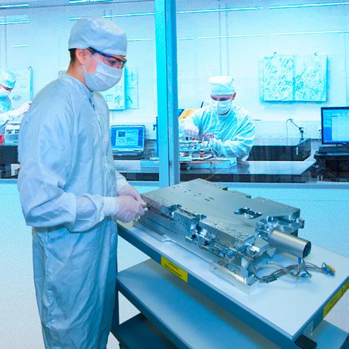
State-of-the-art production technologies and highly specialised employees are responsible for the highest possible quality standards. Our production is subject to stringent specifications and tests.
Our high-precision products are suitable for use in a variety of fields of application:
• Biotechnology
• Semiconductor industry
• Laboratory automation
• Medical technology
• Pick and place machines
• Measuring technology
• Micro-automation
• Nanotechnology
• Surface finishing
• Optics industry
• Processing machines for the micro-sector
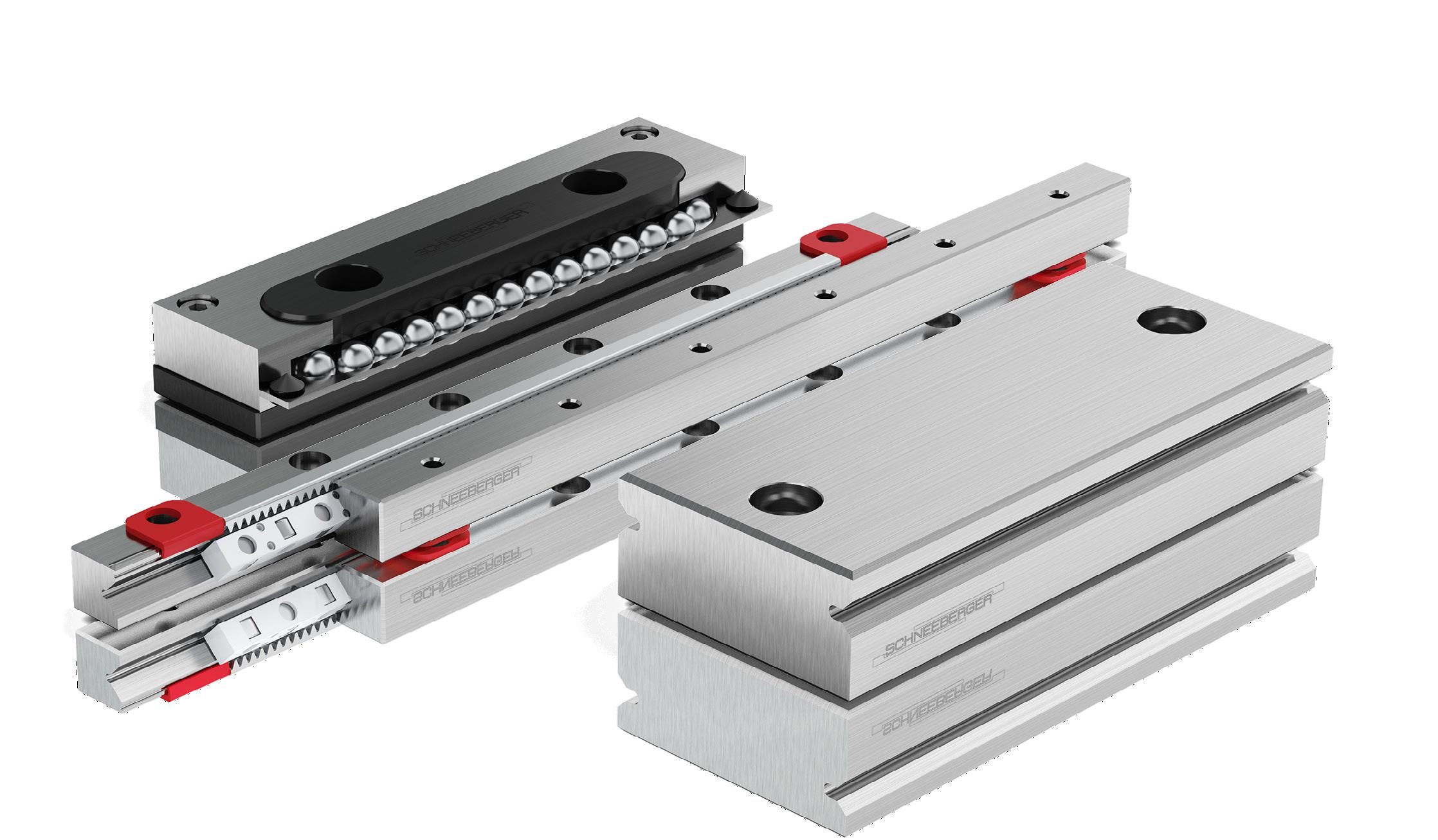
Our linear guideways and recirculating units are available in many designs, sizes and standard lengths and depending on the specific application can be equipped with balls, rollers or needles.
The use of SCHNEEBERGER linear guideways and recirculating units makes it possible to build cost-effective linear guideway systems. The strengths of our products:
• High level of smoothness and consistent accuracy
• No stick-slip effect
Rapid travelling speeds
• Minimal wear
• High level of reliability
• High rigidity
High load carrying capacity
• Used in vacuum and clean room
Our skilled and committed employees will be pleased to advise you at any time on how to develop your applications.
2.1 2D- and 3D-drawings
Drawings and models are available on the Cadenas Part Server free of charge in all formats.
The required download area with additional product information can be found on the web site www.schneeberger.com.
Our website www.schneeberger.com
2.2 Regulations governing substances and limit values
The products presented in this catalogue do not include any forbidden substances based on the RoHs guidelines and do not release chemical substances in accordance with the REACH guidelines.
Links SCHNEEBERGER AG Lineartechnik (Switzerland): www.schneeberger.com/reach-compliance www.schneeberger.com/rohs-compliance
Dynamic loading capacity for a 100'000 m travel distance C corresponds to C100 for SCHNEEBERGER products
C100 Dynamic loading capacity for a 100'000 m travel distance
C50 Dynamic loading capacity for a 50'000 m travel distance
Ceff Effective load carrying capacity per rolling element
Dw Diameter of the rolling element
F Operating load, load of the linear guideway
F1... F2 Individual loads
fh Hardness factor
ft Temperature factor
H Stroke
K Cage length
Kt Load-bearing (cage) length
L Length
L Nominal service life
L1 ... L2 Partial travel distance
Moment load longitudinally and laterally
Tightening torque
Permissible moment load longitudinally and laterally
Q Permissible moment load transversely
t Cage division
t2 Length of the middle section
w Distance Cage start to the middle of the first rolling element
δS Deformation of the connecting structure
δA Deformation of the rolling element including the guide rail
The SCHNEEBERGER range of linear guideways offers you perfect solutions for your specific applications.
features and dimension table, see
Assessment of the advantages
Parameter: displacement force & high level of smoothness
(corrosion-resistant)
not available
The following special versions do not apply in respect of every rail cross-section or every rail length. For details and technical information, see chapter 7.
in special quality (1)
Precision in super special quality (1)
Linear guideways made of corrosion-resistant steel (2)
Run-ins rounded
Prepared for roller cage type
Multi-part linear guideways
Pair of height-matched guideways
coating (4)
Various versions of fixing holes
(1) There are limitations relating to: – corrosion-resistant steel – coatings – maximum rail length
(2) There are limitations relating to: – Maximum rail length (in normal quality as well as in options SQ and SSQ) – Hardness of the steel. This is reduced to a min. 54 HRC, which affects the service life of the linear guideway
(3) – The special versions ZG and SSQ are not possible – Special quality (SQ) only on request
(4) – DryRunner® supports operating without a lubricant. Due to increased cage creep we recommend the additional use of the option «cage control FORMULA-S» – Options ZG and SSQ cannot be supplied. Option SQ on request – There are limitations concerning maximum rail length – This option is not available for the sizes RN/RNG 9 and RN/RNG 12
(5) – Order reference, see p.139
n/a not available
The SCHNEEBERGER range of recirculating units offers you perfect solutions for your specific applications
features and dimension table, see chapter 6
Assessment of the advantages
Parameter: Low displacement force & high level of smoothness
Parameter: High
Material (standard)
Redirection
Special versions
Detailed technical information on the options listed below
3 Overview of product
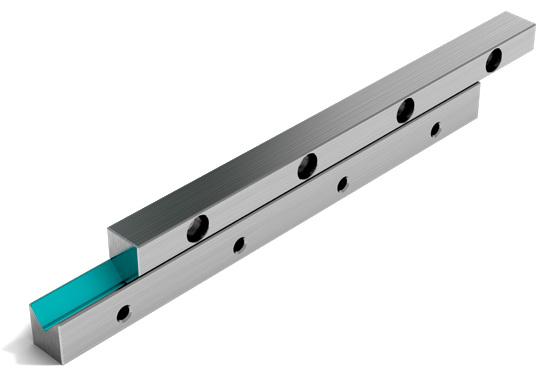
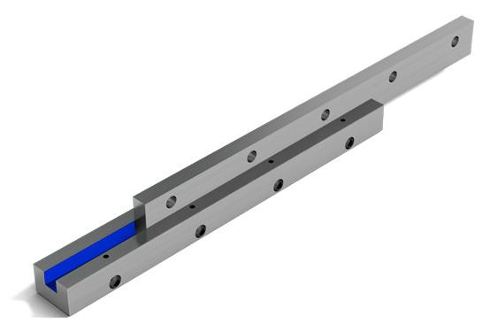
3.3 Earlier generations of the product
Examples of earlier generations of the product, which we are also pleased to manufacture for you today:
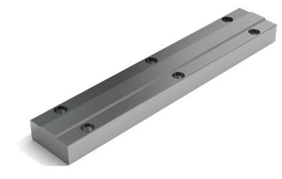
Linear guideway type W/Z
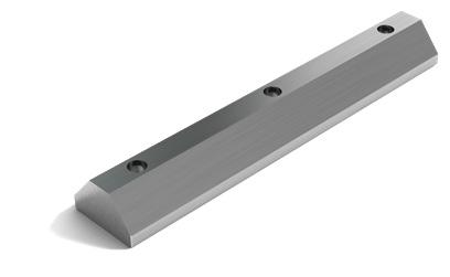
Linear guideway type L/M or J/K
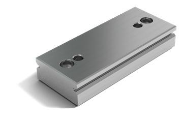
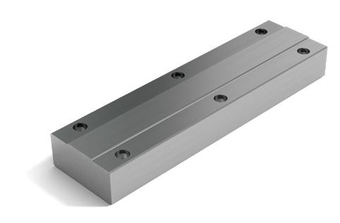
In some applications slideways/slide bearings are more suitable than roller-contact bearings. For such applications SCHNEEBERGER produces steel strips, which are produced with a slideway lining selected by the customer (e.g. Turcite B, Glycodur or Ampco) and then re-ground.
The slideways can be supplied in standardised dimensions for the roller-contact bearing or on a customer-specific basis too.
3.5 Application-specific solutions
Our linear guideways can be universally deployed, but can also be configured on a customer-specific basis ex works. Amongst other things, SCHNEEBERGER offers the following services:
– modified standard
– customer-specific design
– special greasing (cleanroom, vacuum, extraordinary temperature ranges, etc.)
– special packaging
3.4 Slideways
Slideways Flat strips
Linear guideway for a tool grinding machine table
Precision-grinding on tool grinding machines requires a stickslip-free and frictionless guideway to allow longitudinal movement of the table.
Possible SCHNEEBERGER products:
4 linear guideways type R 9-800
2 roller cages AC 9 x 33 rollers
8 end pieces GA 9, GB 9
ATable bearing for an internal cylindrical grinding machine
Internal cylindrical grinding robots require absolutely zerobacklash table guiding in order to meet the stringent requirements of today's grinding technology.
The grinding table displayed is mounted with type N/O linear guideways whose V-shaped needle cages are connected to an oil impulse lubrication system. This creates the conditions needed to control high table speeds with minimal force applied.
Possible SCHNEEBERGER products:
2 linear guideways type O 2535-1'000
2 linear guideways type N 2535-1'000
2 needle cages HW 20 x 725
4 end pieces GH 2535 without wipers
BOpen configuration (floating bearings) for heavy surface grinding machine
Possible SCHNEEBERGER products:
A B
1 linear guideway spec. 45 x 35 x 600-EG (1)
1 linear guideway spec. 45 x 42.5 x1'000
1 roller cage H 25 x 810 mm
2 end pieces special
1 linear guideway type N 3555-600-EG (1)
1 linear guideway type O 3555-1'000
1 needle cage SHW 30 x 810 mm
2 end pieces GW 3555
(1) see chapter 7
Surface-mounted roller guides then come into play particularly when large and heavy workpieces are being machined. The weights of table and workpiece and the grinding pressure have a vertical action on the roller guides.
Cost-effectiveness, simple assembly and a high level of running accuracy characterise this configuration. Expansion of the table resulting from the effect of heat without limitations is also prevented thanks to characterize expansion options.
Its construction is simple and cost-effective. The N/O linear guideway assumes the task of being the lateral linear guideway for the table. As the surface guideway is adjusted level with the N/O, the linear guideway systems can be interchangeddepending on whether the grinding spindle is mounted to the right or left.
Closed V guideway for surface grinding machines
Economic perspectives also determine the structural design of the tables guideways for surface grinding machines. The V-shaped arrangement of the roller guideways creates a closed linear guideway that can be loaded for forces and moments from all directions.
The few components ensure rapid and simple assembly. The stroke and table length ratios are optimal for the use of roller guideways. The basic surfaces of the roof-shaped linear guideways can be machined with extreme efficiency and precision because they are on the same plane. These surfaces also form the basis for achieving high levels of running accuracy.
Possible SCHNEEBERGER products:
2 linear guideways N 3045-900
2 linear guideways O 3045-900
2 needle cages SHW 25 x730 mm
8 end pieces GF 3045
Possible SCHNEEBERGER products:
2 linear guideways RNG 9-700
2 linear guideways RNG 9-450-EG (1)
2 roller cages KBN 9 x 43 rollers
4 end pieces GCN 9
(1) see chapter 7
V guideway for heavy tool grinding machines
Tool grinding machines place very high demands on the roller guideway system of the machine table. High level of running accuracy, minimal friction, stick-slip effect and protected arrangement of the roller guideways are the most important requirements.
The RNG roller guideways used here are ideally suited to this task thanks to their high load carrying capacity. The table construction allows drive mechanisms to be accommodated; the upper part of the table can also be installed with great ease. The preload of the linear guideway system can also be easily set subsequently.
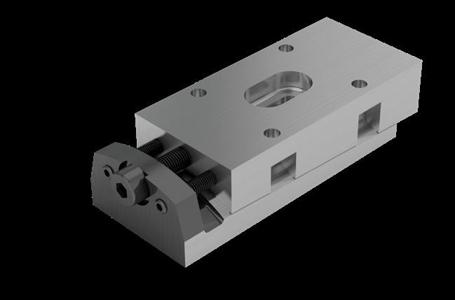
Infeed
device
The infeed device working in vacuum places high demands on the linear guideway system. A U-shaped support forms the supporting element and also acts as the take-up for the linear guideways. The whole system is made of a non-corrosive material and works vertically with a stroke of 2'700 mm.
Linear guideways, which are assembled in the U-shaped basic component, and 4 type SK rolling elements form the actual guide system. Two of the four rolling elements can be adjusted externally and so support optimal preload setting. All individual components of the rolling elements are made out of stainless steel or aluminium.
Possible SCHNEEBERGER products:
A 4 linear guideways R 9-1400-RF (1)-ZG (1) B 4 recirculating units SK 9-150-RF (1)
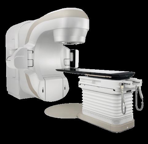
Patient tables
Highly developed, automatic patient tables are used, amongst other things, in computer tomography (CT), magnetic resonance tomography (MRT) or radiotherapy.
All kinematic processes place the highest demands on the linear guideway systems in terms of running accuracy, smoothness, maintenance-free operation, rigidity, ease of installation and radiation resistance.
Possible SCHNEEBERGER products: R 9 linear guideways
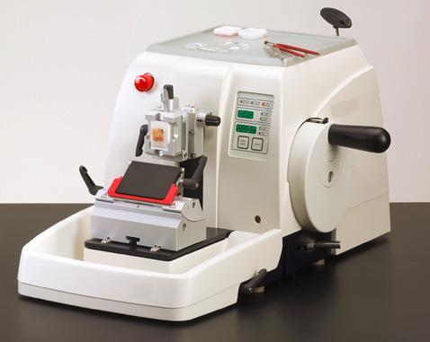
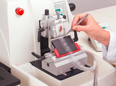
Microtome
Microtomes are cutting devices use to create wafer-thin sections. They are used for microscopic preparations (for example, biological tissue) or analysis of plastics.
Biological material is normally hardened before being cut by means of fixing and then made sliceable by means of «embedding», i.e. inclusion with a fluid substance such as paraffin or synthetic resin. The thickness of the slices is significantly smaller than the diameter of a human hair and is typically around 1 to 100 µm.
Due to these extraordinary requirements, the most stringent demands in terms of smoothness and precision are placed on the linear guideway systems.
Possible SCHNEEBERGER products: RNG 4 linear guideways
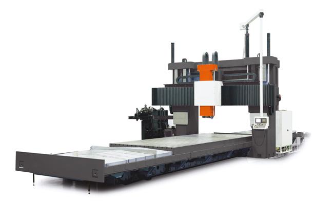
Large-scale machining center
To ensure that it is possible to manufacture with high precision under the most stringent loads, rigid and precise linear guideway systems are critical.
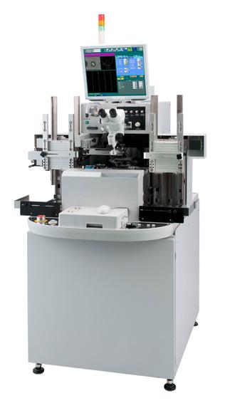
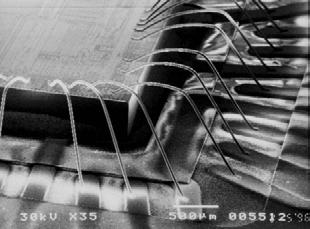
Wire bonder
Wire bonding is the preferred method for making bonds between an integrated circuit (IC) and a printed circuit board. Wire bonding generally represents the most cost-effective and flexible bonding technology with which the thinnest wires are used for bonding electrical connections.
Aluminium, copper or gold wire from 15 µm in diameter is usually used for this technology. The requirements in respect of the linear guideway system for a wire bonder are correspondingly stringent.
• The highest precision and rigidity
• The highest speeds
• The highest level of smoothness
• The highest level of reliability.
Possible SCHNEEBERGER products: SCHNEEBERGER supplies prestigious manufacturers of wire bonders with customer-specific linear guideway systems.
Aluminium wires with a diameter of 25 µm bond the electrodes of microchip with the conductor tracks of a carrier substrate.
Possible SCHNEEBERGER products:
A MONORAIL MR 65
B recirculating unit NRT with preload wedge NRV
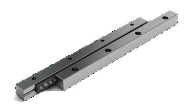
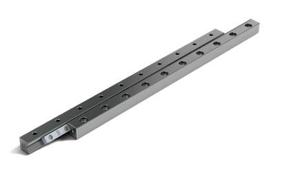
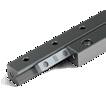
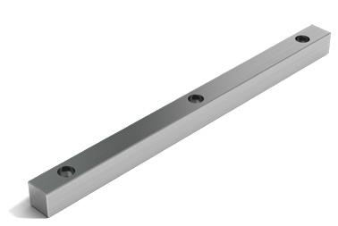
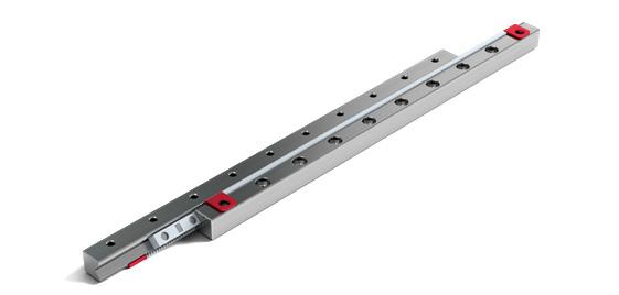
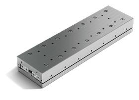
With its type R, SCHNEEBERGER has developed the first standardized cross roller guide, which has defined the global industry standard.
The RD double V-shaped guide supplements the R linear guideway and supports space-saving and cost-effective solutions.
• Rails from through hardened tool steel 1.2842, hardness 58 – 62 HRC
The sizes R/RD 1 and 2 are made out of tool steel 1.3505
• For non-corrosive guideways tool steel 1.4034 and 1.4112 is used
Rolling element made of through hardened roller bearing steel, hardness 58 – 64 HRC
Rolling element
Ball or roller Speed
• 1 m/s
Acceleration
• 50 m/s2 Accuracy
• R and RD linear guideways are available in three quality classes (see chapter 9)
Operating temperatures
-40o C to +80o C
The R and RD design can be combined with the following products:
• recirculating unit type SK, SKC and SR
Type R with balls
Typ R with rollers
Type RD
5.1 Type R and RD
5 Linear guideways
Dimensions and load capacities type R
(1) The lengths listed are standard; other lengths are of course available. The maximum lengths are listed on page 26.
(2) B designates the width of a guideway. B2 designates the width over both guideways.
(3) Select accessories as follows: Cage type: page 27 and 28, end pieces: pages 29 and, end and fixing screws: page 30
5 Linear guideways
(1) The lengths listed are standard; other lengths are of course available. The maximum lengths are listed on page 26.
(2) B designates the width of a guideway. B2 designates the width over both guideways.
(3) Select accessories as follows: Cage type: page 27 and 28, end pieces: pages 29 and, end and fixing screws: page 30
Dimensions and load capacities of type RD
(1) The lengths listed are standard; other lengths are of course available. The maximum lengths are listed on page 26.
(2) Positioning hole option available upon customer request (per NZ customer drawing)
(3) Select accessories as follows: Cage type: page 27 and 28, end pieces: pages 29 and, end and fixing screws: page 30
*applies to the mix of type R linear guideways of the same sizes
(2) Positioning hole option available upon customer request (per NZ customer drawing)
(3) Select accessories as follows: Cage type: page 27 and 28, end pieces: pages 29 and, end and fixing screws: page 30
The detail of the rail chamfer is shown in the chart below. Please note that the part number and company logo are marked opposite to the datum and supporting surfaces.
Accessories for type R and RD
Roller cage type AC
Compatible with:
Linear guideway type R and RD, Sizes 1 to 12
Design: Rollers fixed in place
Installation method: For normal application and certain overrunning cage applications
Material: Sizes 1, 2 POM
Size 3 PA GF 30% As from size 6 PA GF 30%, plastic/steel wire composite construction. The wire is made out of stainless steel.
Option:
Corrosion-resistant rollers
Roller cage type AA-RF
Compatible with:
Linear guideway type R and RD, Sizes 1, 2, 3 and 6
Design: Rollers fixed in place
Installation method: Not suitable as an overrunning cage
Material:
Cage and rollers made of corrosion-resistant steel and thus also suitable for use in vacuum
Ball cage type AK
Compatible with:
Linear guideway type R and RD, Sizes 1 to 12
Design: Balls retained
Installation method:
For normal application and certain overrunning cage applications
Material:
Sizes 1, 2 and 3 POM
As from size 65 PA GF 30%, plastic/ steel wire composite construction. The wire is made out of stainless steel.
Roller cage type EE
Compatible with:
Linear guideway type R and RD, Sizes 6
Design:
- The clearances of the guide rails are matched with the EE roller cage, which consequently works as a contaminant wiper. Displacement resistance is increased by the wiper function.
- Rollers fixed in place
- Only used with linear guideways with add-on designation EE
- Select end pieces of type GB or GC
Installation method:
Not suitable as an overrunning cage and for freely surface-mounted guideways
Material: PE
End screws type GA 1 to GA 12
Compatible with: Linear guideway R 1 to R 12
Installation method: For horizontal installation Not suitable for cage reset
End piece type GB 1
Compatible with: Linear guideway R 1
Installation method: No restrictions
Scope of supply: Including end screws
End piece type GB 2
Compatible with: Linear guideway R 2
Installation method: No restrictions
Scope of supply: Including end screws
End piece type GB 3 to 12
Compatible with: Linear guideway R 3 to R 12
Installation method: No restrictions
Scope of supply: Including end screws
End piece type GC 3 to GC 12
Compatible with: Linear guideway R 3 to R 12
Installation method: For overrunning cages
Scope of supply: Including end screws
End piece type GC-A 3 to GC-A 12 (with wipers)
Compatible with:
Linear guideway R 3 to R 12
Design: with felt wiper
Installation method: No restrictions
Scope of supply: Including end screws
Fastening screws with thin shaft type GD 3 to GD 15
Special feature:
To compensate for differences in hole pitches
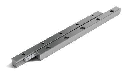
Type RN
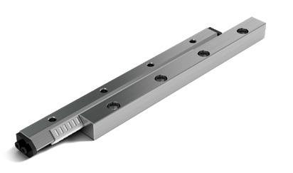
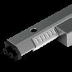
The type RN linear guideway is the logical optimised version of the R guideway. It has identical installed dimensions, but due to the optimized contact surfaces of the guideway tracks is, however, higher performing. The reduced gap width between the guide rails also provides better protection against contaminants.
• Rails made of through hardened tool steel 1.2842, hardness 58 – 62 HRC For non-corrosive guideways tool steel 1.4034 and 1.4112 is used
• Rolling element made of through hardened roller bearing steel, hardness 58 – 64 HRC
Rolling element
• Roller Speed
1 m/s
Acceleration
• 50 m/s2
300 m/s2 with cage control
Accuracy
• RN linear guideways are available in three quality classes (see chapter 9)
Operating temperatures
• -40o C to +80o C
5.2 Type RN
5 Linear guideways
Dimensions and load capacities of type RN
(1) The lengths listed are standard; other lengths are of course available. The maximum lengths are listed on page 34.
(2) B designates the width of a guideway. B2 designates the width over both guideways.
(3) Select accessories as follows: Cage type: page 35, end and fixing screws: page 36
988
1318
1647
1976
2306
2635
1086
2171
2714
3257
3800
4342
4885
5428
(1) The lengths listed are standard; other lengths are of course available. The maximum lengths are listed on page 34.
(2) B designates the width of a guideway. B2 designates the width over both guideways.
(3) Select accessories as follows: Cage type: page 35, end and fixing screws: page 36
5 Linear guideways
Maximum lengths for type RN
Rail chamfer
The detail of the rail chamfer is shown in the chart below. Please note that the part number and company logo are marked opposite to the datum and supporting surfaces.
Accessories for type RN
Roller cage type KBN
Compatible with:
Linear guideway type RN Sizes 3 to 12
Design: Rollers fixed in place
Installation method:
For normal application and certain overrunning cage applications
Material: POM (Vacuum-compatible up to 10-7 mbar)
Option:
Corrosion-resistant rollers
Type KBS roller cage for the cage control FORMULA-S
Detailed information on FORMULA-S is listed under chapter 7.8.
Compatible with:
Linear guideway type RN Sizes 3 to 6
Design: Rollers fixed in place With integral pinion
Installation method: For normal application and certain overrunning cage applications
Material:
POM (Vacuum-compatible up to 10-7 mbar)
Option: Corrosion-resistant rollers
End screws type GAN
Compatible with:
Linear guideway RN 3 and RN 4
Installation method: For horizontal installation
End screws type GA
Compatible with:
Linear guideway RN 6 to RN 12
Installation method: For horizontal installation
Fastening screws with thin shaft type GD 3 to GD 15
Special feature:
To compensate for differences in hole pitches
Compatible with:
Linear guideway type RN 3 to RN 12
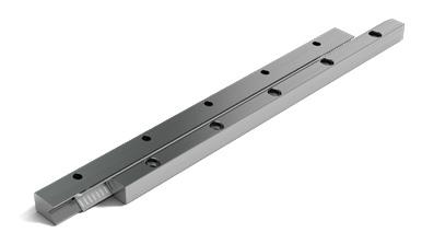
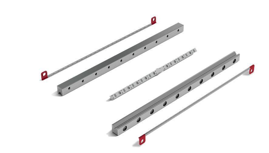
Type RNG
Like type RN, the type RNG linear guideway is based on the type R linear guideway. Like type RN, it has larger contact surfaces for the guideway tracks, which means its performance is significantly enhanced. Compared with types R and RN its cross-section is, however, smaller, which means that it represents a cost-effective solution without compromise.
Rails from through hardened tool steel 1.2842, hardness 58 - 62 HRC
• For non-corrosive guideways tool steel 1.4034 and 1.4112 is used
• Rolling element made of through hardened roller bearing steel, hardness 58 - 64 HRC
Rolling element
• Roller Speed
• 1 m/s
Acceleration
50 m/s2
• 300 m/s2 with cage control
Accuracy
RNG linear guideways are available in three quality classes (see chapter 9)
Operating temperatures
• -40o C to +80o C
5.3 Type RNG
Dimensions and load capacities of type RNG
(1) The lengths listed are standard; other lengths are of course available. The maximum lengths are listed on page 40.
(2) B designates the width of a guideway. B2 designates the width over both guideways.
(3) Select accessories as follows: Cage type: page 41, end pieces: pages 42 and 43, fixing screws: page 43
A-A RNG 4-6 RNG 9-12
(1) The lengths listed are standard; other lengths are of course available. The maximum lengths are listed on page 40.
(2) B designates the width of a guideway. B2 designates the width over both guideways.
(3) Select accessories as follows: Cage type: page 41, end pieces: pages 42 and 43, fixing screws: page 43
Maximum lengths for type RNG
Rail chamfer
The detail of the rail chamfer is shown in the chart below. Please note that the part number and company logo are marked opposite to the datum and supporting surfaces.
Type RNG accessories
Roller cage type KBN
Compatible with:
Type RNG linear guideway Sizes 4 to 12
Design: Rollers fixed in place
Installation method:
For normal application and certain overrunning cage applications
Material: POM (Vacuum-compatible up to 10-7 mbar)
Option:
Corrosion-resistant rollers
Type KBS roller cage for the cage control FORMULA-S
Detailed information on FORMULA-S is listed under chapter 7.8.
Compatible with:
Type RNG linear guideway Sizes 4 to 9
Design:
Rollers fixed in place With integral pinion
Installation method: For normal application and certain overrunning cage applications
Material:
POM (Vacuum-compatible up to 10-7 mbar)
Option: Corrosion-resistant rollers
End piece type GBN 4 and GBN 6
Compatible with:
Linear guideway RNG 4 and RNG 6
Installation method: No restrictions
Scope of supply: Including end screws
End piece type GBN 9 and GBN 12
Compatible with:
Linear guideway RNG 9 and RNG 12
Installation method: No restrictions
Scope of supply: Including end screws
End piece type GCN 4 and GCN 6
Special feature:
For overrunning cage
Compatible with:
Linear guideway RNG 4 and RNG 6
Installation method: No restrictions
Scope of supply: Including end screws
End piece type GCN 9 and GCN 12
Special feature:
For overrunning cage
Compatible with:
Linear guideway RNG 9 and RNG 12
Installation method: No restrictions
Scope of supply: Including end screws
End piece type GCN-A 4 and GCN-A 6
Special feature:
With wipers made of plastic
Compatible with:
Linear guideway RNG 4 and RNG 6
Installation method: No restrictions
Scope of supply: Including end screws
End piece type GCN-A 9 and GCN-A 12
Special feature:
With wipers made of plastic
Compatible with:
Linear guideway RNG 9 and RNG 12
Installation method: No restrictions
Scope of supply: Including end screws
Fastening screws with thin shaft type GDN 4 to GDN 15
Special feature:
To even out differences in the hole spacings
Compatible with: Linear guideway type RNG 4 to RNG 12
Type N/O
Benchmark data
• -40o C to +80o C 5.4 Type N/O
The type N/O linear guideways are equipped with needle cages and are particularly suitable for applications involving high loads. SCHNEEBERGER N/O bearings have a lower moving resistance due to our composite cage.
(1) The lengths listed are standard; other lengths are of course available. The maximum lengths are listed on page 48.
(2) B designates the width of a guideway. B2 designates the width over both guideways.
(3) Select accessories as follows: Cage type: page 49 and 50, end pieces: pages 51 and 52, fixing screws: page 52
3555
3555
3555
3555
3555
-GD 3555 -GD 1435
Maximum lengths type N/O
Rail chamfer
The detail of the rail chamfer is shown in the chart below. Please note that the part number and company logo are marked opposite to the datum and supporting surfaces.
Accessories for type N/O
Needle cage type SHW
Design:
Needles fixed in plastic provides lower displacement forces and smoother running
Installation method: For normal application and certain overrunning cage applications
Material: Stainless steel and plastic PA 12 GF 30 %
Needle cage type SHW with cage control (KZST)
Detailed information on the cage control is listed under Chapter 7.9.
Design:
Needles fixed in plastic. Thus smaller displacement forces and smoother running.
Installation method: For normal application and certain overrunning cage applications
30
5 Linear guideways
Needle cage type HW
Design:
Needles fixed
Installation method:
For normal application and certain overrunning cage applications
Material:
Standard
- Size HW 10 is made out of tool steel
- All other sizes in aluminium
Optional
- All cages are available in steel
Needle cage type HW with cage control (KZST)
Detailed information on the cage control is listed under Chapter 7.9.
Design:
Needles fixed
Installation
For
and
overrunning cage applications
Material:
Optional - All cages are available in steel
5 Linear guideways
End piece type GH
Special feature: For overrunning cage
Installation method: No restrictions
Scope of supply: Including end screws
End piece type GH-A
Special feature: Wipers made of felt
Installation method: No restrictions
Scope of supply: Including end screws
End piece type GFN/GFO
Installation method: No restrictions
Scope of supply: Including end screws
End piece type GW
Special feature: For overrunning cage
Installation method: No restrictions
Scope of supply: Including end screws
End piece type GW-A
Special feature: Felt Wipers
Installation method: No restrictions
Scope of supply: Including end screws
Fastening screws with thin shaft type GD 6 to GD 1435
Special feature: To compensate for differences in hole pitches
(1) Tightening torques apply for materials with a tensile strength of > 360N/mm2
Type M/V
the type M/V linear guideway is similar to type N/O, but differs in its external dimensions. Equipped with needle cages, its is particularly suitable for applications involving a higher load. SCHNEEBERGER M/V bearings have a lower moving resistance due to our composite cage.
• Rails from through hardened tool steel 1.2842, hardness 58 – 62 HRC For non-corrosive guideways tool steel 1.4034 and 1.4112 is used
• Rolling element made of through hardened roller bearing steel, hardness 58 – 64 HRC
Rolling element
• Needle Speed
1 m/s
Acceleration
• 50 m/s2
200 m/s2 with cage control
Accuracy
• Type M/V linear guideways are available in three quality classes (see chapter 9)
Operating temperatures
5 Linear guideways
Dimensions and load capacities type M/V
150 204 231
200 272 308 300 420 473
400 560 631
500 700 788
600 840 946
150 392 411
200 522 548
300 820 815
4020 100 261 274
400 1093 1087
500 1367 1358
600 1640 1630
200 893 874
300 1339 1311
400 1786 1748
500 2232 2185
600 2678 2622
700 3125 3059
800 3571 3496
900 4018 3933 1000 4464 4370
a) for the 100 mm length, the following applies: L1 = 35 mm (2 x )
b) for the length 100 mm, the following applies: L1 = 50 mm
(1) The lengths listed are standard; other lengths are of course available. The maximum lengths are listed on page 56.
(2) B designates the width of a guideway. B2 designates the width over both guideways.
(3) Select accessories as follows: Cage type: page 57 and 58, end pieces: pages 59, fixing screws: page 60
5 Linear guideways
300 2176 2265
400 2901 3020
500 3626 3775
600 4351 4530
700 5076 5285
800 5802 6040
900 6527 6795 1000 7252 7550
1934
300 2807 3019
400 3743 4025
500 4678 5032
600 5821 6038
700 6791 7044
800 7499 8051
900 8436 9057 1000 9374 10321
4014 4271
400 5352 5694
500 6690 7118
600 8290 8544
700 9672 9968
800 10700 11530
900 12038 12822
1000 13375 14247
(1) The lengths listed are standard; other lengths are of course available. The maximum lengths are listed on page 56.
(2) B designates the width of a guideway. B2 designates the width over both guideways.
(3) Select accessories as follows: Cage type: page 57 and 58, end pieces: pages 59, fixing screws: page 60
Rail chamfer
The detail of the rail chamfer is shown in the chart below. Please note that the part number and company logo are marked opposite to the datum and supporting surfaces.
Accessories type M/V
Needle cage type SHW
Compatible with: Linear guideway type M/V
Design:
Needles fixed in plastic provides lower displacement forces and smoother running
Installation method: For normal application and certain overrunning cage applications
Material:
Stainless steel and plastic PA 12 GF 30 %
Needle cage type SHW with cage control (KZST)
Detailed information on the cage control is listed under Chapter 7.9.
Compatible with: Linear guideway type M/V
Design:
Needles fixed in plastic. Thus smaller displacement forces and smoother running.
Installation method: For normal application and certain overrunning cage applications
Material: Stainless steel and plastic PA 12 GF 30 %
Needle cage type HW
Compatible with: Linear guideway type M/V
Design:
Needles fixed
Installation method: Specifically suitable as an overrunning cage
Material: Standard
- Size HW 10 is made out of tool steel - All other sizes in aluminium Optional
- All cages are available in steel
Needle cage type HW with cage control (KZST)
Detailed information on the cage control is listed under Chapter 7.9.
Compatible with:
Linear guideway type M/V
Design:
fixed
- All cages are available in steel
End piece type EM/EV
Compatible with: For all M/V rail sizes
Installation method: No restrictions
Scope of supply: Including fastening screws
End piece type EAM
Special feature: With wipers made of plastic
Compatible with: For all M/V rail sizes
Installation method: No restrictions
Scope of supply: Including fastening screws
End piece type EAV
Special feature:
With wipers made of plastic
Compatible with: For all M/V rail sizes
Installation method: No restrictions
Scope of supply: Including fastening screws
5 Linear guideways
Fastening screws with thin shaft type GD 3015 to GD 8050
Special feature:
To compensate for differences in hole pitches
* Tightening torques apply for materials with a tensile strength of > 360N/mm2
** Situation 2 applies only for hole variant G (see chapter 7.10)
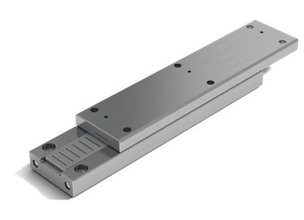
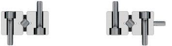
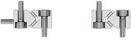
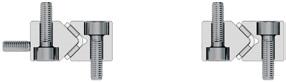
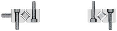
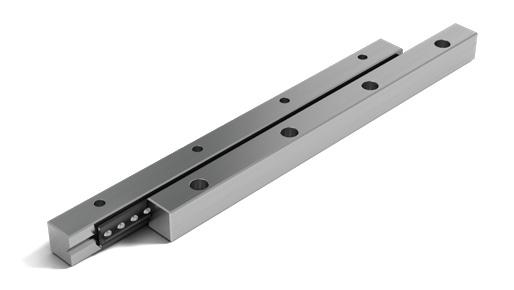
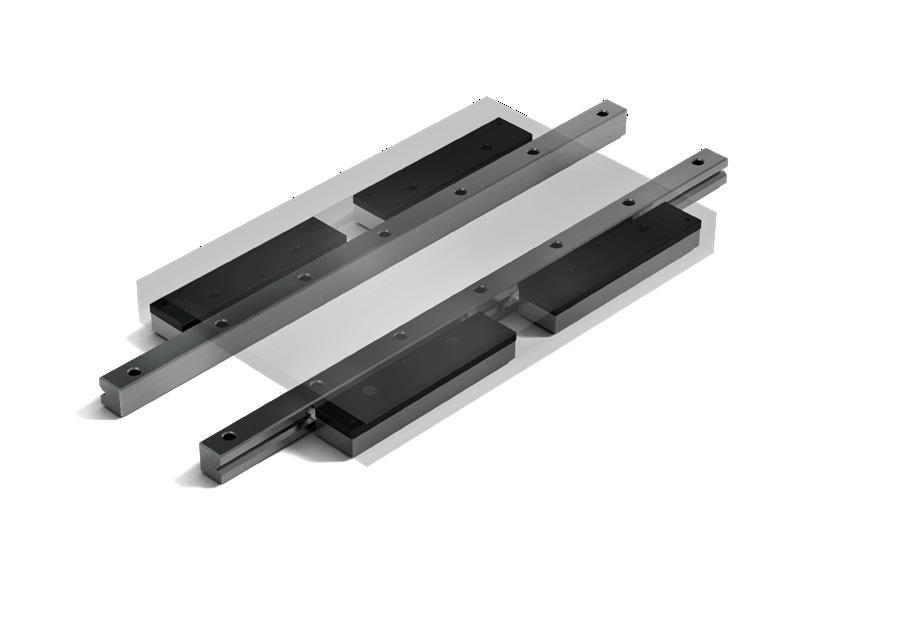
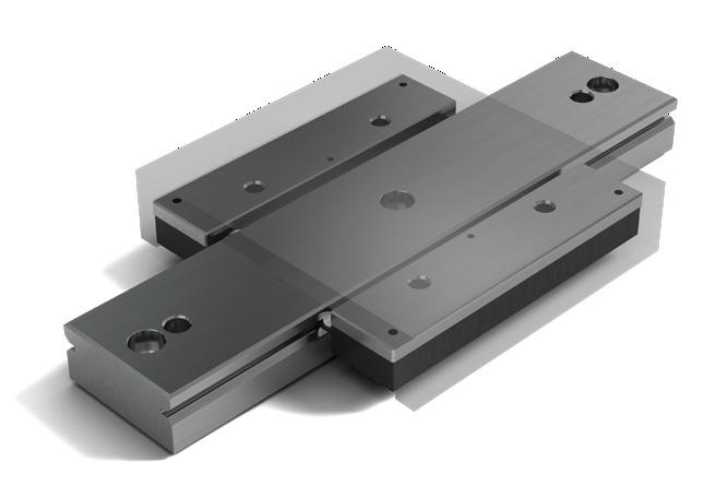
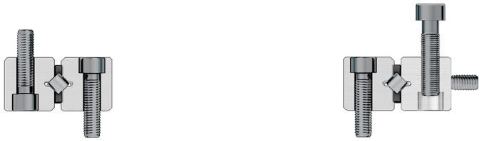
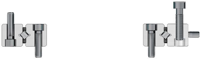
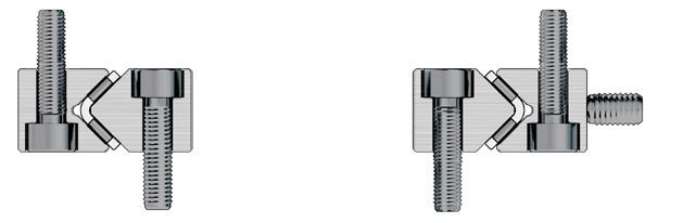
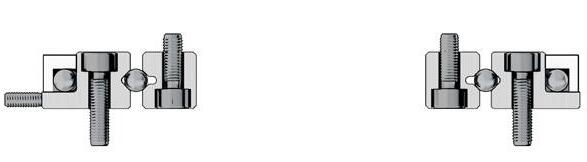
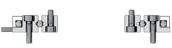
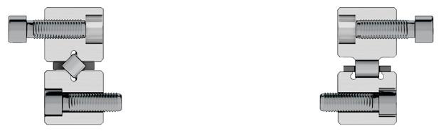
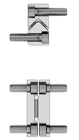
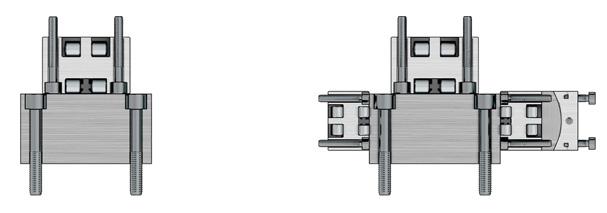
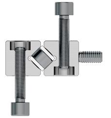
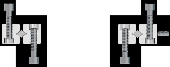
Application with recirculating units and linear guideways of type R
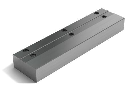
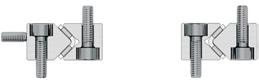
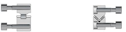
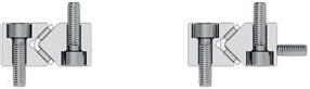
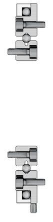
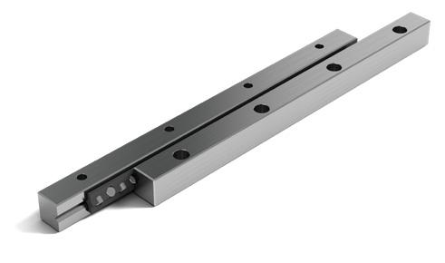
Application with recirculating units and a linear guideway of type RD
Recirculating units support high-precision, rigid and compact structures with unlimited travel. They are used as standard with linear guideways of type R or RD.
The SCHNEEBERGER product range includes recirculating units in different versions and for different load capacities; with rollers or balls, with damping elements or for minimal lubrication .
The range is modular in structure and depending on the type includes sizes from 1 to 12.
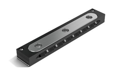
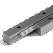
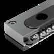
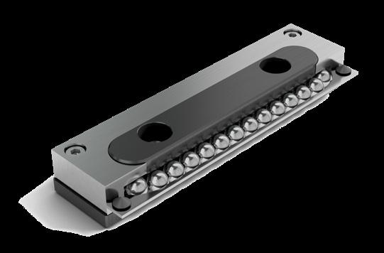
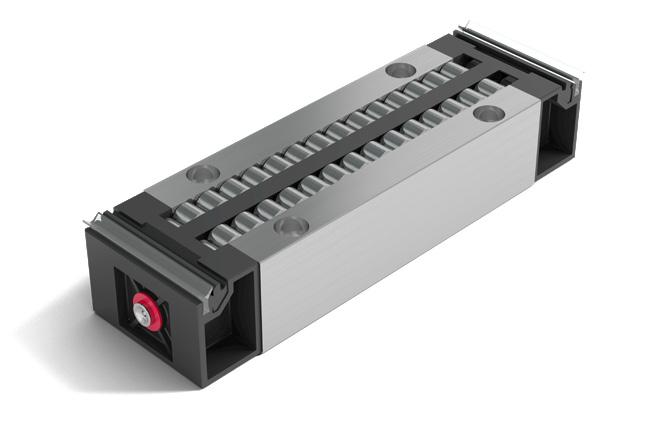
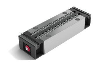
The type SK recirculating unit is equipped with balls and is suitable for small to medium loads.
This recirculating unit is used combined with SCHNEEBERGER linear guideways of type R and/or RD. The SK units can be used in space saving designs that have equal loading in all directions.
Sizes 6 and 9 (size 12 on request) can additionally be equipped with damping elements (type designation SKD). These provide improved smoothness with slightly reduced load carrying capacity.
Benchmark data
Supporting structure
• Hardened and ground with high precision Materials
• Supporting structure made of through hardened tool steel, hardness 58 - 62 HRC
• Rolling element made of through hardened roller bearing steel, hardness 58 - 64 HRC
• Transmission part in sizes 1, 2, 9 and 12 made of anodized aluminium
• Transmission part in sizes 3 and 6t depending on the length made of plastic or aluminium
• Non-corrosive version on request
• Damping elements for SKD made of plastic
• Wipers made of plastic
Wipers
• From size 3 interchangeable track wipers are made from plastic as standard fitted
Speed
• 2 m/s
Acceleration
• 50 m/s2
Operating temperatures -40o C to +80o C
Same installation with the following recirculating units
• • SKC and SR
Can be combined with the following products
• Linear guideway type R and RD
6.1 Type SK and SKD
Type SK Type SKD
Dimensions and load capacities type SK and SKD
Retaining web may not be used as a stop Wiper from size SK 3-075
1) SK 12 and SKD 12 are only available upon request
Lube hole
Installed dimensions and permissible torque for type SK and SKD
Permissible torques for type SK and SKD
1)SK 12 and SKD 12 are only available upon request
Installed dimensions for type SK and SKD
SK and SKD
1) SK 12 und SKD 12 sind nur auf Anfrage erhältlich
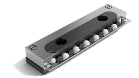
The recirculating unit type SKC was developed for minimal lubrication, vacuum and clean room applications. It is made out of DURALLOY® coated steel and has ceramic balls, which are separated from one another by balls made out of TEFLON®
This recirculating unit is used combined with SCHNEEBERGER linear guideways of type R and/or RD. The SKC units can be used in space saving designs that have equal loading in all directions. It is suitable for small to medium loads.
Benchmark data
Supporting structure
• Hardened and ground and coated with high precision
Materials
• Supporting structure made of stainless steel 1.4034, DURALLOY® coated, hardness min. 54 HRC
• Transmission part made out of stainless steel 1.4034
• Rolling element made of ceramic (balls made of TEFLON® between the ceramic balls are responsible for minimal friction)
Speed 2 m/s
Acceleration
• 50 m/s2
Operating temperatures
• -150o C to +200o C
Same installation with the following recirculating units
• SK, SKD and SR
Can be combined with the following products Linear guideway type R and RD
6.2 Type SKC
Dimensions and load capacities of type SKC
* Loading capacity for minimal lubrication
Installed dimensions and permissible torques for type
Permissible torques for type SKC
Installed dimensions for type SKC
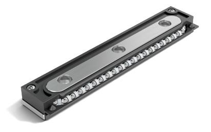
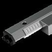
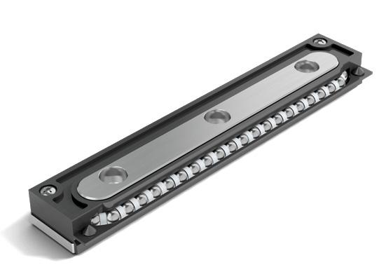
The SR recirculating units has cross rollers and is suitable for medium to high loads.
This recirculating unit is used combined with SCHNEEBERGER linear guideways of type R and/or RD. In this way space-saving designs can be created that can be equally loaded in all directions.
Benchmark data
Supporting structure
• Hardened and ground with high precision
Materials
Supporting structure made of through hardened tool steel, hardness 58 – 62 HRC
• Rolling element made of through hardened roller bearing steel, hardness 58 –64 HRC
Transmission part depending on the length made of plastic or anodized aluminium
• Stainless steel on request
• From size 3 the rollers are laid in plastic shoes
Speed
• 2 m/s
Acceleration
• 50 m/s2
Operating temperatures -40o C to +80o C
Same installation with the following recirculating units
• SK, SKD and SKC
Can be combined with the following products
• Linear guideway type R and RD
6.3 Type SR
Dimensions and load capacities of type SR
Lube hole
1) SR 12 sind nur auf Anfrage erhältlich
Installed dimensions and permissible torques for type SR
Torques for type SR
1) SR 12 sind nur auf Anfrage erhältlich
Installed dimensions for type SR
SR 2-032 15.5 37 M2.5
SR 3-075 23.5 57 M3
SR 6-100 40 94 M5
SR 6-150 40 94 M5
SR 9-150 61 150 M6
SR 12-2001) 78 175 M8
1) SR 12 sind nur auf Anfrage erhältlich
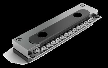
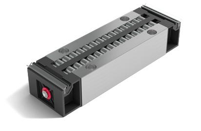
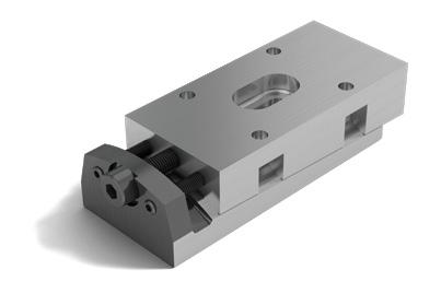
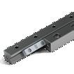
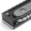
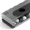
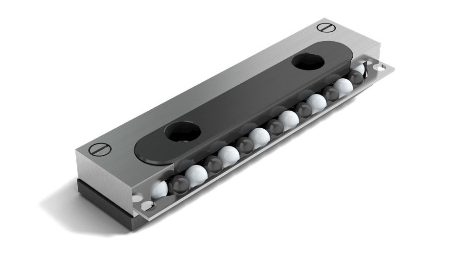
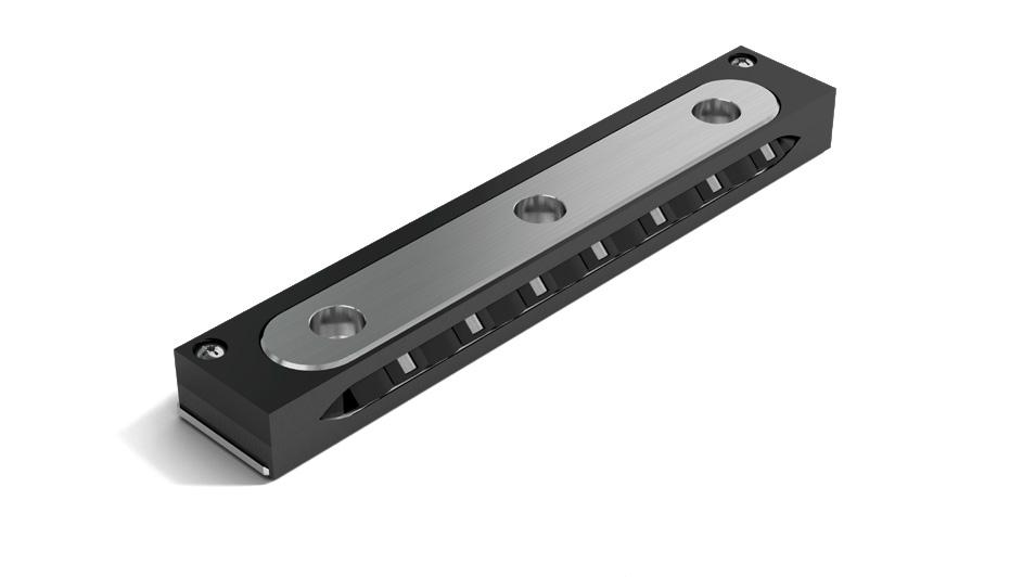
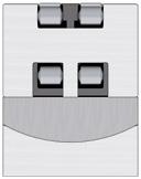
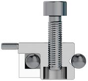
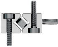
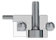
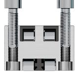
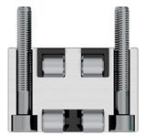
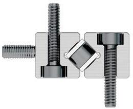
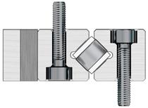
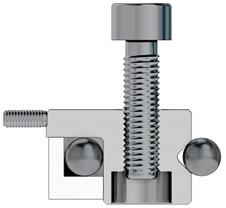
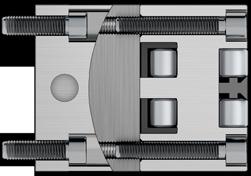
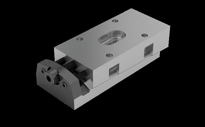
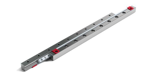
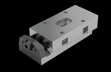
This roller recirculating unit is designed for medium to heavy loads. Solutions to demanding applications can be created using NRT, NRV, and suitable guideways.
Advantages/benefits of the NRT
• Two independent tracks, the small amount of roller play and the optimal ratio of roller length and roller diameter are responsible for minimal lateral forces.
• The large number of rollers and the optimised roller run-ins are responsible for minimal travel pulsation and a low coefficient of rolling friction
• High degree of rigidity thanks to three-point support on the rear
• Protected roller return
• Double-lipped wipers on each side
• Can also be supplied matched as an option, sorted within 5µm
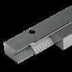
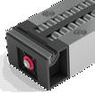
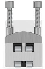
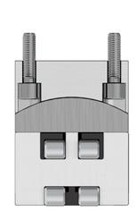
Advantages/benefits of the preload wedge NRV
This preload wedge is used for setting preload. The NRV with its concave and convex supporting surfaces is also able to even out minor angular errors and deformations in the connecting structure.
Benchmark data
Supporting structure
• Hardened and ground with high precision
Materials
• Supporting structure made of through hardened tool steel, hardness 58 – 62
HRC
• Rolling element made of through hardened roller bearing steel, hardness 58 – 64
HRC
• Transmission parts and wipers made of plastic
Speed
1 m/s
Acceleration
• 50 m/s2
Operating temperatures
• -40o C to +80o C
Recirculating unit type NRT
Preload wedge type NRV
6.4 Type NRT (with NRV)
Dimensions and load capacities of type NRT
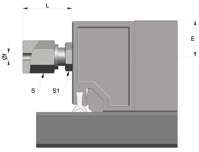
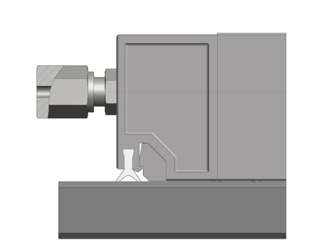
Recirculating unit type NRT
lubricating nipple Ø 4 type D1a on both sides Lubricating hole
Dimensions and load capacities of type NRV
Preload wedge NRV
Setting screw Lubricating hole Locking and jacking screws
7 Options for linear guideways
7.1 Quality classes (SQ and SSQ)
The run and positioning accuracy of an application depends directly on the geometric precision of the guideway, its careful alignment, as well as the precision and stiffness of the surrounding construction.
Depending upon the application different levels of accuracy are required.
SCHNEEBERGER linear guideways are available in three quality classes to address a variety of applications:
NQ* Normal quality Represents normal requirements in mechanical engineering
SQ Special quality In case of very stringent requirements
SSQ Super special quality In case of the most stringent requirements
Note:
*NQ represents standard quality and is not subsequently listed as an order code
The corresponding tolerance values (Δ) for parallelism of the running surfaces in relation to the reference and locating surfaces can be seen in the diagram below.
In terms of the quality classes SQ and SSQ the following limitations technically exist:
- Max. lengths according to the table „Dimensions and load capacities“ of the respective product.
- Coatings (see chapter 7.6 and 7.7).
7.2 Guideways made of corrosion-resistant steel (RF)
For certain applications such as, for example, medical technology, food industry or in a vacuum, the guide rails can be made of corrosion-resistant steel.
Notes:
- The max. rail length in normal quality as well as in options SQ and SSQ is limited (see „dimensions and load capacities“ of the respective product).
- The hardness of the steel reduces compared with tool steel to min. 54 HRC, which should be taken into account in the food calculation.
7 Options for linear guideways
7.3 Run-ins rounded (EG)
Overrunning cages are expedient to used if a short table is to be moved on a long guideway track. As a result the upper part is at any time supported over its entire length, which has a positive effect on the load carrying capacity and rigidity.
So that the cage run-in causes as little pulsation as possible, the short rails are provided with rounded run-ins. The run-ins are ground following manufacture of the guideway track.
Note:
On rare occasions (e.g. under very high preload), in spite of rounded run-ins the pulsation of the overrunning cage can have a disruptive effect on the application. This phenomenon can be largely eliminated by taking appropriate measures (on request).
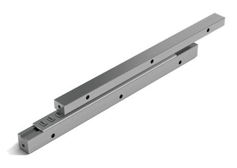
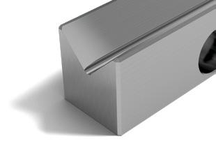
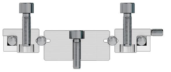
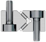
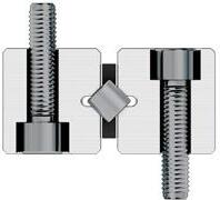
7.4 Multi-part linear guideways (ZG)
Is the desired overall length of the guideway is greater than the maximum length listed in this catalogue, individual rails can be ground together. The offset between the individual guideway tracks for this is max. 0.002 mm. The length tolerance L is within +/- 2 mm.
During installation it is important to pay attention to the numbering at the butt joint.
7 Options for linear guideways
7.5 Height-matched guideways (HA and EHA)
Height-matched guideways (HA)
The height difference between two linear guideway pairs (A1 and A2) is 0 mm to 0.3 mm as standard. This difference can be too large depending on the application. For height-matched guideways, the H dimensions of the linear guideways (H1 to H3 and H2 to H4) are measured and sorted so that the height difference of both linear guideway pairs (A1 and A2) can be reduced to a maximum of 0 mm to 0.02 mm. In addition, the guideways are numbered the same in pairs. This numbering is consecutive for multiple guideway pairs.
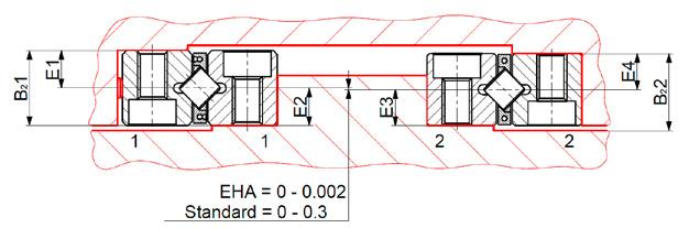
E dimension of height-matched guideways (EHA)
The width difference between two linear guideways (B21 to B22) is 0 mm to 0.02 mm as standard. This difference can be too large depending on the application. For the E dimensions of height-matched guideways, the E dimensions of the linear guideways (E1 to E3 and E2 to E4) are measured and sorted so that the width difference of both linear guideway pairs (B21 and B22) can be reduced to a maximum of 0 mm to 0.002 mm. In addition, the guideways are numbered the same in pairs. This numbering is consecutive for multiple guideway pairs.
Note: EHA option only available up to size 6
Notes:
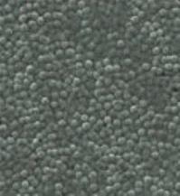
For applications for which corrosion protection and/or increased wear resistance of the surfaces is required, coating the guideways with DURALLOY® is recommended.
Technical information
- Max. rail length 3'000 mm
- Hardness HRC 64 - 74
- Coating thickness 2.5 – 4.0 µm
- Structure "Pearlescent" (see figure)
- Vacuum-compatible 10-7 mbar
The advantages of DURALLOY®
- Increased wear resistance
- Corrosion protection
- The pearl structure acts as a lubricant reservoir
- Good emergency running characteristics
- Protection from abrasive corrosion
- High degree of chemical resistance
- Cleanroom compatible
- FDA approved
- The ZG special versions (multi-part linear guideway) and the maximum quality grade SSQ are not possible.
- Special quality SQ only on requeste
7.6 DURALLOY ® coating (DU)
7.7 DryRunner coating (DR and DRC1)
Without lubrication, the running surfaces of linear guideways are completely destroyed after only 10,000 revolutions.
A guideway coated with DryRunner allows for more than 100 million revolutions without lubrication and thus a service life lubrication that is 10,000 times longer. In a vacuum, an unlubricated guideway coated with DryRunner allows more than 50 million revolutions.
To achieve outstanding running performance, we recommend the DryRunner coating in combination with minimal lubrication using a common lubricant.
Technical information
- The coating is only applied to the running surfaces. From a production standpoint, it is possible to coat other exterior surfaces but not the supporting and locating surface of the guideway.
- DryRunner does not provide any protection against corrosion. If corrosion-resistant guideways are required, the guideway must be ordered in a rust-resistant material (RF) or with a Duralloy coating (DU).
The advantages of DryRunner
- Good emergency running properties insufficient lubrication
- Suitable for applications in air or vacuum
- Minimal wear due to abrasion
- High chemical resistance
Notes
- DryRunner permits operation with minimal lubrication.
- We recommend using the FORMULA-S cage control (KS) (see section 7.8).
- The special versions of the multi-part linear guideway ZG and the quality class SSQ are not possible. Quality class SQ on request (see section 7.4 and 7.1).
The causes of cage creep
- High accelerations and speeds
- Vertical installation of the guideway
- Uneven load distribution
- Protruding cage
- Different heat expansion coefficients
- Design and installation (lacking rigidity and/or accuracy of the connecting structure)
The benefits of FORMULA-S
- No cage slipping and thus consistent load conditions
- Avoids correction strokes
- No force required for cage reset
- Accelerations up to 300 m/s2 (30 g)
- speed 1 m/s
- Easy to install and/or uninstall
- Extended service life
- Vacuum-compatible up to 10-7 mbar
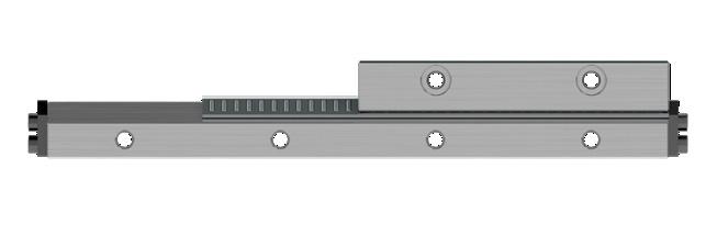
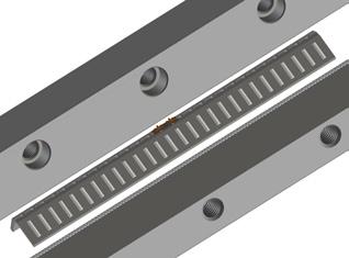
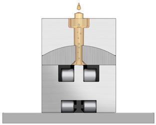
In every linear guideway the cage can be shifted from the centre along the longitudinal axis. Cage creep reduces the optimal load distribution and requires a correct stroke to return the cage to a centered position. the correction stroke requires a large expense of energy.
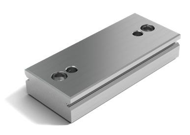
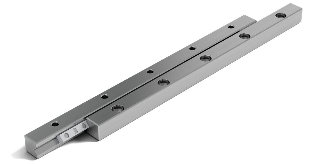
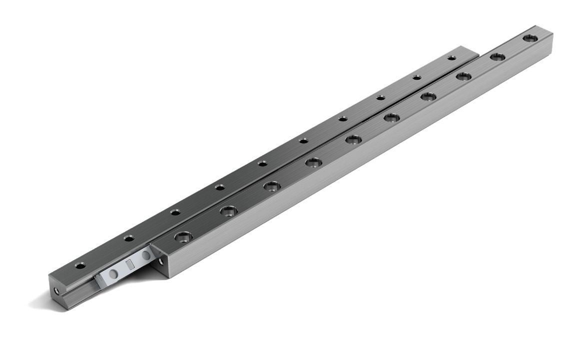
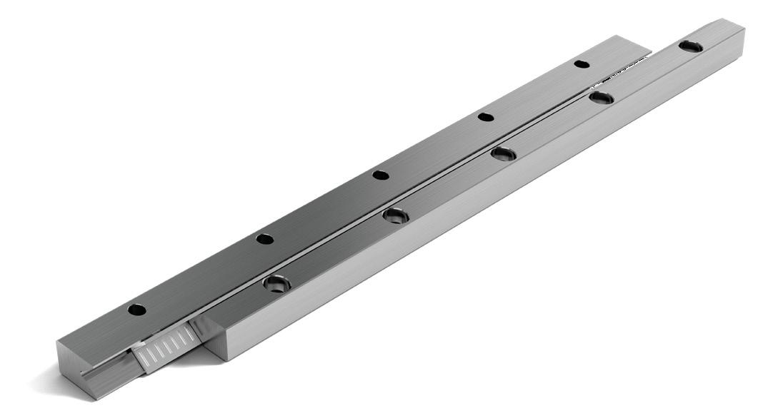
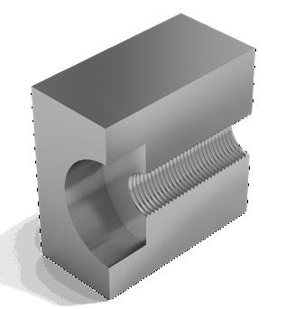
1 Clips hold the gear rack in position (alternative fastening variants on request)
2 Rack
3 Cage with pinion
Suitable for the following guideways
- RN 3, RN 4 and RN 6
- RNG 4, RNG 6 and RNG 9
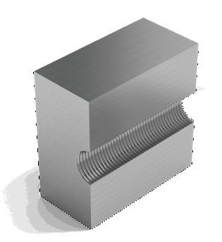
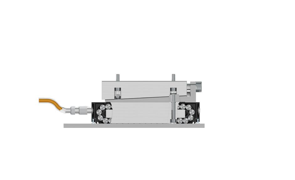
FORMULA-S meets the requirements fully in respect of productivity and costeffectiveness. It is very robust and consists of only a few components.
Connecting structure
In the case of the connecting structure, the thickness smin should be taken into account. The remaining dimensions correspond to the guideways RN and RNG (see chapter 5, dimensions and load capacities).
7.8 Cage control FORMULA-S (KS)
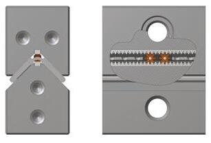
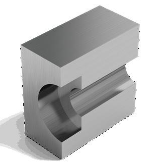
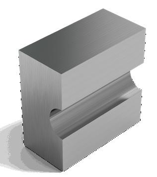
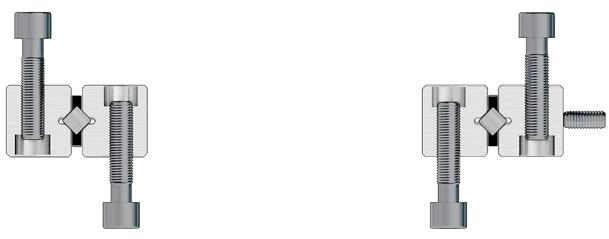
7.9 Cage control for N/O and M/V guideways (KZST)
The needle guideways of type N/O and M/V can be fitted with a cage control which ensures that process security is significantly increased. The causes and effects of cage creep are set out in chapter 7.8.
The benefits and advantages
- Perfect load distribution
- Avoids correction strokes
- No force required for cage reset
- Accelerations up to 200 m/s2 (20 g)
- Max. speed 1 m/s
- Extended service life
This type of cage control fully meets the requirements in terms of productivity and cost-effectiveness. It is very robust, has a simple structure and consists of only a few components:
A A gear rack made of tool steel per guide rail
B Two pinions made of tool steel per cage
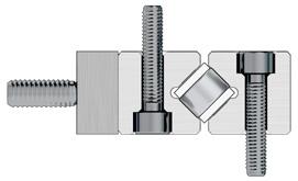
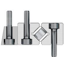
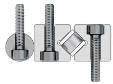
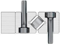
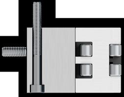
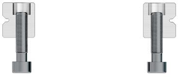
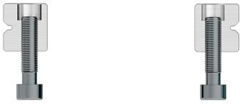
7.10 Fixing Hole Variants (V, G, or D)
The SCHNEEBERGER standard
Most SCHNEEBERGER guideways have a counter bore with threading as standard. This is not suitable for the guideways of type M/V (variant V). This design supports the use of a tapped fixing hole as well as the through fixing hole. The dimensions can be seen in the respective product specifications (chapter 5).
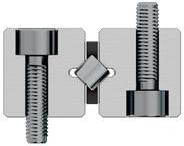
Special versions type V (standard for linear guideway of type M/V)
Dimensions for R-guideways
Dimensions for RN-guideways
Dimensions for RNG-guideways
Dimensions for RNG guideways with a cage control system (KS)
Dimensions for N/O-guideways
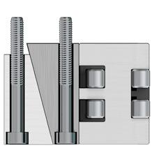
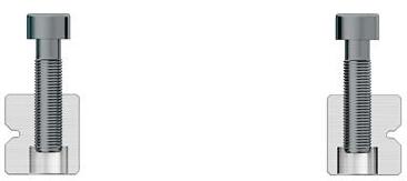
Special versions type G
Dimensions for R-guideways
Dimensions for
Dimensions for RNG-guideways
Dimensions for N/O-guideways
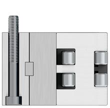
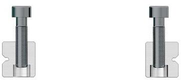
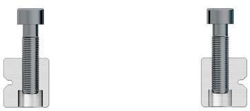
Special versions type D
Dimensions for
Dimensions for
Dimensions for RNG-guideways
Dimensions for M/V-guideways
8 Recirculating unit options
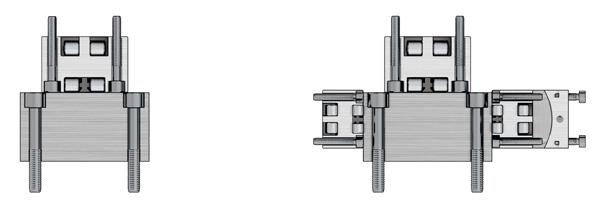
8.1 Matched recirculating units (GP)
If two or more recirculating units are arranged next to or behind one another, they need to be ordered (matched in pairs) with the add-on designation GP.
The types in bold are standard. The types in size 12 are available on request
Markings:
The recirculating units in the same group are designated with a number, i.e. the same number corresponds to the exact same tolerance group.
Markings:
Colored rings around the lube nipple mark the relevant tolerance group.
1) Types of size 12 are only available on request
Colored rings
8 Recirculating unit options
8.2 Centralised lubricating system (ZS) for recirculating units NRT
9 Linear guideways standard parameters
9.1 Tolerance of the supporting surface to the track Type R, RN and RNG
In addition to the previously mentioned geometric precision as set out in chapter 7.1, SCHNEEBERGER guideways are also manufactured to the dimensions of the supporting surface in relation to the track within a very tight tolerance (+/- 0.005mm).
Advantages:
• Interchangeability is guaranteed at all times
• In most cases additional matching of the guideways is surplus to requirement
Type N/O and M/V Type RD
9 Linear guideways standard parameters
9.2 Length tolerances and distances between fixing holes
9.3 Operating temperatures
Length L ≤300 mm: ±0.3 mm
Length L >300 mm: ±0.1 % of L
Hole pitch L1: ±0.3 mm
Mass Xn ≤350 mm: ±0.3 mm
Mass Xn >350 mm: ±0.08 % of xn
The fixing holes are manufactured before the hardening process, which is why the length tolerances and spacings differ from the usual standards. The deviations can be offset using undercut fastening screws of type GD or GDN (see chapter 5) and/ or by choosing a suitable hole (see chapter 7.10).
SCHNEEBERGER linear guideways can be used at operating temperatures from –40º C to +80º C. For brief periods temperatures up to +120º C are possible.
9.4 Speeds and accelerations
The following limit values apply for the standard designs:
Linear guideways R, RD, RN, RNG, N/O and M/V
Linear guideways RN and RNG with Cage control FORMULA-S
Linear guideways N/O and M/V with cage control
9.5 Friction, running accuracy and smoothness
When manufacturing the linear guideways, SCHNEEBERGER places great value on a high level of smoothness. Transitions, run-ins and run-outs or the quality of the synthetic materials and synthetic composite cages are given top priority. This also applies in respect of the rolling elements used, which must satisfy the most stringent quality demands.
For guideways with cages under normal operating conditions a friction factor of 0.0005 to 0.0030 can be assumed.
10 Recirculating unit standard parameters
10.1 Operating temperatures
SCHNEEBERGER recirculating units can be used at operating temperatures from –40º C to +80º C (for brief periods temperatures up to +120º C are possible). For type SKC the temperature range is –150º C to +200º C.
10.2 Speeds and accelerations
The following limit values apply for the standard designs:
10.3 Friction, running accuracy and smoothness
When manufacturing the recirculating units, SCHNEEBERGER places great value on a high level of smoothness. Transitions, run-ins and run-outs or the quality of the synthetic materials are given top priority. This also applies in respect of the rolling elements used, which must satisfy the most stringent quality demands.
For recirculating units under normal operating conditions a friction factor of 0.005 can be assumed.
11.1 Linear guideways
The varied areas of application require different characteristics of linear guideways and recirculating units.
Various parameters and considerations are critical for product selection. These are described in detail below.
Relationship between stroke H and length of the guideway L
If the stroke is below 400 mm, the following formula applies:
H < 0.7 L
If the stroke is above 400 mm, the following formula applies:
H < 1 L
L H = Length of the linear guideway in mm = Possible Stroke in mm
Calculating the number of rolling elements (RA) per cage
Calculating the cage length K
K < L - H1
If the stroke is symmetrical, the following formula applies: H = H1 + H2 = H12
If the stroke is asymmetrical, the following formula applies: H = H1 + H1 H > H1 + H2 H12 = H1 + H2
= Cage length in mm
= Length of the linear guideway in mm
= Possible Stroke in mm
= Large partial stroke in mm = H/2
= Small partial stroke in mm = H/2
= Effective partial stroke in mm
The stroke must be limited by means of stops on the table and not by the cages. The stops should preferably be fitted along the axis of symmetry of the guideways to avoid additional forces acting on the linear guideways.
a) For cage types KBN, AA-RF, AC, AK, EE, SHW, HW
Kt
K = (RA - 1) · t + 2 · w => RA = K - 2 · w + 1 t or RA = Kt + 1 t
b) For cage type KBS
K = (RA - 2) · t + tz + 2 · w => RA = K - (2 · w + tz) + 2 t or RA = Kt - tz + 2 t
K RA w = Cage length in mm = Total available rolling element per cage = Distance from cage start to the middle of the first rolling element in mm t Kt tz = cage division in mm = Load-bearing length in mm = Length of the middle section for the KBS cage
The relationship between the cage length K and the average guideway spacing Q K > 1
K Q = Cage length in mm = Average linear guideway spacing in mm
The maximum permissible installation ratio in the case of overrunning cages
Overrunning cages are expedient if a short table is to be moved on a long guideway track. In each case the short rail for the guideway must have a rounded run-in (special version EG, see chapter 7.3) so that the overrunning cage causes as little pulsation as possible.
Not every cage is suitable for this application. The maximum cage overrun depends on the position of the rails and on the cage material.
Maximum permitted installation ratios L to L1: – for fixed guideways 1 : 2 – for laid on guideways 1 : 4
Installation variants for linear guideways
There are four installation variants for linear guideways. The various linear guideways can be also used with wipers in the form of end pieces (a1)*. In these four cases, the following length ratios result:
Variant 1
Linear guideway with:
- Equal length rails
- Symmetric / asymmetric stroke
a) Without end screws, end pieces, and end pieces with wipers
K ≤ L – H1
Ltot = L + H1 + H2
b) For end screws, end pieces, and end pieces with wipers**
K L – H1
Ltot L + H1 + H2 + 2 · a1
* a1 end screws, end pieces, and end pieces with wipers, see chapter 5
** Wipers can influence the run characteristics of the linear guideways
Variant 2
Linear guideway with:
- Equal length rails
- Unidirectional stroke
a) Without end screws, end pieces, and end pieces with wipers
K ≤ L – H1
Ltot = L + H1
b) For end screws, end pieces, and end pieces with wipers**
K ≤ L – H1 – a1
Ltot L + H1 + a1
With this design, the linear guideways must be staggered to one another by the amount a1
= Cage length in mm
= Possible Stroke in mm
= Large partial stroke in mm = H/2
= Small partial stroke in mm ≤ H/2
= Effective partial stroke in mm
= Length in mm
= Length in mm
= Total length in mm
= Thickness of the end piece in mm
* a1 end screws, end pieces, and end pieces with wipers, see chapter 5
** Wipers can influence the run characteristics of the linear guideways
Variant 3
Linear guideway with:
- Unequal length rails
- Symmetric / asymmetric stroke
- Short rails attached
a) Without end screws, end pieces, and end pieces with wipers
K ≤ L – H1
Ltot = L + H1 + H2
b) For end screws, end pieces, and end pieces with wipers**
K ≤ L – H1 – 2 · a1
Ltot = L + H1 + H2
Variant 4
Linear guideway with: - Unequal length rails
- Symmetric / asymmetric stroke
- Long rails attached
a) Without end screws, end pieces, and end pieces with wipers
K ≤ L – H1
Ltot = L + H1 + H2 (wenn L ≥ L1 – H12)
Ltot = L1 (wenn L ≥ L1 – H12)
b) For end screws, end pieces, and end pieces with wipers**
K ≤ L – H1 – a1
Ltot L + H1 + H2 + 2 · a1 (wenn L ≥ L1 – H12)
Ltot = L1 (wenn L ≥ L1 – H12)
= Cage length in mm
= Possible stroke in mm
= Large partial stroke in mm = H/2
= Small partial stroke in mm ≤ H/2
= Effective partial stroke in mm
= Length in mm
= Length in mm
= Total length in mm
= Thickness of the end piece in mm
Recirculating units
When using recirculating units, theoretically there is not restriction in stroke. The stroke is only restricted by the length of the guide rails.
In terms of the spacing K between the recirculating units and the rail spacing Q, the following ratios are recommended as a guideline:
When using one recirculating unit per rail: Kt > 1 Q
When using more than one recirculating unit per rail: K > 1 Q K Kt Q
= Spacing between the recirculating units in mm = Load-bearing length in mm = Average rail spacing in mm
12 Load carrying capacity and service life
12.1 Basic principles
The load capacities are based on DIN ISO standard 14728 for roller-contact bearings.
In accordance with DIN, in most applications a permanent overall deformation of 0.0001 times the rolling element diameter can be permitted without adversely affecting the operating behavior of the bearing. This is referred to as the static capacity, C0. When designing a new application, we recommend the equivalent static load be in line with the dynamic load capacity ( C ) to avoid plastic deformation.
The dynamic loading capacity C is the load at which a nominal service life L of 100,000 meters of travel is achieved. It is important to note when calculating the service life that not only the load, which acts vertically on the guideway, should be taken into account but the load range of all acting forces and moments.
The service life corresponds to the travel distance in meters, which is travelled from a guideway. This is before the first sign of material fatigue occurs within the roller guideway elements. The nominal service life is achieved when 90 % of the guideways of identical construction reach or exceed the corresponding travel distances under normal operating conditions.
Critical for the dimensioning of the guideways are the loads occurring in the ratio with the dynamic loading capacity C.
Definition of service life
As previously mentioned, the dynamic loading capacity C100 is based on a service life of 100,000 meters. Other manufacturers frequently indicate the loading capacity C50 for a service life of 50,000 meters. The resulting load capacities from this are more than 20 % higher than specified in the DIN ISO standard.
Conversion examples
For balls
Convert load capacities in accordance with DIN ISO standard to C50: C50 = 1.26 ∙ C100
Convert C50 load capacities in accordance with DIN ISO standard to: C100 = 0.79 ∙ C50
For rollers and needles
Convert load capacities in accordance with DIN ISO standard to C50: C50 = 1.23 ∙ C100
Convert C50 load capacities in accordance with DIN ISO standard to: C100 = 0.81 ∙ C50
C50 C100 = dynamic loading capacity C in N for 50,000 meters of travel distance = dynamic loading capacity C in N for 100,000 meters of travel distance defined in accordance with DIN ISO standard
12.2 Short strokes
A continuous lubricating film forms below the rolling element
We talk about short stroke applications when a rolling element does not travel past the position of the next rolling element during a stroke.
Local depressions from wear and tear form on the tracks.
At highly frequent strokes the lubricating film is also interrupted
Because the tracks are concentrated at these points (depressions from wear and tear form), the precision and service life of the guideway is reduced. When the strokes are highly frequent, a standard lubricant is no longer able to reach the points of contact.
Wear and tear can be deferred with suitable lubricants and regular lubrication strokes
Short strokes curtail the service life of the guideway considerably. The service life of the guideway(s) can only be determined by means of testing.
Normal stroke
Short stroke
12.3 Calculating the service life L in accordance with the DIN ISO standard
The formulas for calculating service life are:
For rollers and needles: L = a �Ceff � 10 ∙ 105 m 3 P
For balls:
L = a �Ceff �3 105 m P a Ceff P L
= Event probability factor
= Effective load carrying capacity per rolling element in N
= Dynamic, equivalent load in N = Nominal service life in m
Event probability factor a
The load carrying capacities for roller-contact bearings correspond to the DIN ISO standard. This represents a value from the service life calculation, which is exceeded with a probability of 90 % during operational use of the guideway.
If the previously mentioned theoretical service life probability factor of 90% is not adequate, the service life values will need to be adjusted by a factor a.
Effective load carrying capacity Ceff
External influences such as track hardness and temperature can reduce the loading capacity C which means that Ceff needs to be calculated.
Effective load carrying capacity per rolling element in N
Hardness factor = Temperature factor = Max. permissible load carrying capacity per rolling element in N
Hardness factor fH
Materials in a frictionless guideway, which deviate from the standard conditions (HRC 58 - 62), can be recorded with the factor fH:
Temperature factor fT
Increased temperatures influence the operating conditions (material properties) and must be taken into account using the factor fT
The loads (F) acting on a linear guideway system are subject to frequent fluctuations during operation. This set of circumstances should be taken into account when calculating service life. The varying load absorption of the guideway at varying operating conditions during the travel distance is described as being the dynamic equivalent load P.
Stepped load
Formula for rollers and needles:
Formula for balls:
Sinusoidal load
= 0.7 Fmax
= Equivalent load in N Individual load in N during the partial travel distance L
Ln = Max. load in N =
+
Ln = total travel during one load cycle in mm = partial travel distance in mm of one individual load during a load cycle
Example calculation with a linear guideway of type RNG 6-300 with KBN 6 cage
• an event probability of 97% is selected; the corresponds to a factor a of 0.44
• the dynamic loading capacity of a roller (for KBN 6 cage) is 1'800 N. If 16 rollers are used, the loading capacity of the guideway is 16 ∙ 1'800 N = (28'800 N)
• the application generates a total load on to the guideway of 10'000 N
With the previously mentioned values, the following calculation for service life L is:
= 0.44
If the service life is requested in hours, the travelled stroke H (in meters) and the time t (in seconds) required for the stroke movement must be known.
The service life Lh is calculated as follows:
= L ∙ � = Service life in hours
3'600
The correction factor Rtmin
It was explained on the above pages how service life should be calculated from the given load carrying capacity and the occurring load. In doing so, the number of load bearing rolling elements per cage (Rt) should be taken into account.
Similarly important is estimating the behavior of the surrounding structure when transmitting forces to the frictionless guideway. Then an elastic deformation or a geometric error in a machine bed lead to the fact that only a part of the installed rolling element effectively absorbs load.
Reliable statements on this application-specific issue can usually only be made with a great deal of difficulty, for example by taking measurements on functioning models or using calculations based on the method of finite elements. The result of this is that normally dimensioning takes place by taking simplified measures, i.e. the external load is divided up on to few rolling elements using the correction factor Rtmin
To determine Rtmin first of all the connecting structure must be assessed based on the following values from historical experience:
= deformation of the connecting structure in µm
= deformation of the rolling element including the guide rail in µm
(see chapter 12.5)
= load in N
= Lever arm distance on x-axis in mm
= load-bearing cage length in mm
= Number of load-bearing rollers
= Correction factor
A = rigid B = normal
To calculate Rtmin according to the diagram applies
structure A (rigid) B (normal)
X > Kt Rtmin to RT/4 Rtmin
X < Kt as per diagram as per diagram
For Rtmin the following applies Rolling element type Cage types
2 Balls AK
1 Rollers AA, AC, EE, KBN and KBS
5 Needles SHW and HW
0.5 Recirculating unit with rollers SR and NRT
1 Recirculating unit with balls SK, SKD and SKC
Example calculation no. 1
Linear guideway R6 with cage type AK 6/20
X = 200 mm
Kt = 171 mm
Consequently the calculation method in accordance with "X > Kt" applies
The linear guideway is horizontally arranged Thus, the following applies:
• Rt = RA/2 = 20/2 = 10 rollers
Calculation for a rigid structure:
• In accordance with the table, a ball count Rtmin to Rt/4 applies
• Rtmin corresponds to 2 balls Rt/4 corresponds to 2.50 balls
Calculation for a normal structure:
• In accordance with the table, Rtmin applies Rtmin corresponds to 2 balls
Example calculation no. 2
Linear guideway R6 with cage type AK 6/11
X = 75 mm
Kt = 90 mm
Consequently the calculation method in accordance with «X < Kt» applies
Calculation for a rigid structure:
According to the diagram, X = 0.83 of Kt (75 mm : 90 mm) and consequently Rt /2 With 11 load-bearing balls, this results in 5.5 balls (11 load-bearing balls : 2)
Calculation for a normal structure:
According to diagram Rt/8. With 11 load-bearing balls, this results in 1.3 balls (11 : 8)
12.4 Example calculations
The following example calculations illustrate the procedure for some typical problems.
Example 1
Searched for:
Equivalent load P per roller
Assumption:
Linear guides type R 6
AC 6 cage with 8 rollers (= RA)
F = 350 N
X = 120 mm
For the roller cage type AC 6 the following applies:
Kt = (RA – 1) ∙ t = (8 – 1) ∙ 9 = 63
Rtmin = 1 roller
C = 530 N
(per chapter 5.1 techn. specifications of AC 6 cage)
Note:
The asymmetric distribution of force is most safely taken into account when the load on the number of load bearing rolling elements (Rtmin) for the guideway is reduced.
Calculation for P per roller
P = F x 1 Kt 2 Rtmin
= 350 ∙ 120 ∙ 1 = 334 N 63 2 1
P is smaller than C. The design is correct in this way.
P F C X RA Rtmin t Kt
= Equivalent load in N per roller
= load in N
= Max. permissible load carrying capacity per rolling element in N
= Lever arm distance on x-axis in mm
= Total available rolling element per cage
= Correction factor
= cage division in mm
= Load-bearing length in mm
Example 2
Searched for:
Equivalent load P per roller
Assumption:
Linear guides type R 6
Roller cage type AC 6 cage with 20 rollers (= RA)
F = 6500 N
C = 530 N (per chapter 5.1 techn. specifications of AC 6 cage)
RT = RA 2
= 20 = 10 rollers 2
Calculation for P per roller
P = F 1 2 RT = 6'500 1 = 325 N 2 10
P is smaller than C. The design is correct in this way.
= Distance from cage start to the middle of the first rolling element in mm
= cage division in mm
= Equivalent load in N per roller
= load in N
= Max. permissible load carrying capacity per rolling element in N
= Total available rolling element per cage
= Number of load-bearing rolling elements per cage
Example 3
Searched for:
Equivalent load P per ball
Assumption:
Rigid slide structure
Linear guides type R 6
Cage type AK 6 with 12 balls (= RA); t = 9 mm (according to chapter 5.1, technical data for the AK 6 cage)
RA = RT = 12 balls
Rtmin = 3 = Rt/4 according to diagram on page 101
Kt = (RA – 1) ∙ t
F = 240 N
X = 75 mm (distance F to opposing force)
C = 65 N (according to chapter 5.1, technical data for the AK 6 cage)
Calculation for P per ball:
P = F X 1 Kt 2 Rtmin = 240 75 1 = 30 N 99 2 3
P is smaller than C. The design is correct in this way.
t P F C Rtmin RA Rt Kt
= cage division in mm
= Equivalent load in N per ball
= load in N
= Max. permissible load carrying capacity per rolling element in N
= Correction factor
= Total available rolling elements per cage
= Number of load-bearing rolling elements per cage
= Load-bearing length in mm
Example 4
Searched for:
Equivalent load P per roller and the suitable size RNG guideways
Assumption:
Type RNG linear guideways
Roller cage type KBN with 10 rollers (RA)
F = 15'000 N
X = 50 mm
Q = 100 mm
RT = RA 2 = 10 = 5 rollers 2
Calculation for P per roller
P1 = F ∙ X 1 Q RT = 15'000 ∙ 50 1 = 1'500 N 100 5
P2 = F RA = 15'000 = 1'500 N 10
P = P1 + P2 = 1'500 + 1'500 = 3'000 N
P (P1, P2) F X Q C RA Rt
= Equivalent loads in N per roller
= load in N
= Lever arm distance on x-axis in mm
= Medium linear guideway distance in mm
= Max. permissible load carrying capacity per rolling element in N
= Total available rolling element per cage
= Number of load-bearing rolling elements per cage
Definition of the suitable guideway size:
According to product specification for the KBN cage (chapter 5.2 or 5.3) if C = 3'900 N were to be selected
The roller size 9 is suitable. Thus select cage KBN 9 and the linear guideway RNG 9, provided the service life has been fulfilled.
F F
Example 5
Searched for:
Equivalent load P per needle
Assumption:
Linear guideways type N/O 2025
SHW 15 cage, cage length K = 194 mm
(w = 2.9 mm according to techn. specifications of the SHW 15 cage)
F = 5'000 N
X = 280 mm
Q = 75 mm
C = 750 N (according to techn. specifications for the AC 15 cage)
RA = � K - 2w + 1 � 2 t = � 194 - 5.8 + 1 � 2 = 96 needles 4
Rt = RA = 48 needles 2
Calculation for P per needle:
P = F X 1 Q Rt
= 5'000 ∙ 280 1 = 389 N 75 48
P is smaller than C. The design is correct in this way.
w t P F X Q C Rt RA K
= Distance from cage start to the middle of the first rolling element in mm
= cage division in mm
= Equivalent load in N per needle
= load in N
= Lever arm distance on x-axis in mm
= Medium linear guideway distance in mm
= Max. permissible load carrying capacity per rolling element in N
= Number of load-bearing rolling elements per cage
= Total available rolling element per cage
= Cage length in mm
Q
= Distance from cage start to the middle of the first rolling element in mm
= cage division in mm
= Equivalent load in N per roller
= load in N
= Lever arm distance on x-axis in mm
= Lever arm distance 1 on x-axis in mm
= Medium linear guideway distance in mm
= Max. permissible load carrying capacity per rolling element in N
= Number of load-bearing rolling elements per cage
= Total available rolling element per cage
= Cage length in mm
= Load-bearing length in mm
= Longitudinally
= Laterally
Example 6
Searched for:
Equivalent load P per roller
Assumption:
Rigid structure
Linear guides type R 12
Cage type AC 12, length K = 400 mm
F = 2'000 N
X = 500 mm
X1 = 200 mm
Q = 100 mm
C = 2'500 N (see chapter 5.1, technical specifications for the AC 12 cage)
For the roller cage AC 12 the following applies:
Kt = K - 2w = 400 - 22 = 378 mm RA = Kt + 1 t = 378 + 1 = 22 rollers 18
Rt = RA 2 = 22 = 11 rollers 2
X > Kt = Rt/4 (accordingtothediagramonpage101)
RTQ = Rt
RTL = Rt = 11 = 2.75 rollers(roundeddownto2) 4 4
Calculation for P per roller
Load laterally PQ = F X1 1 Q RTQ = 2'000 200 1 = 364 N 100 11
Load longitudinally
PL = F X ∙ 1 Kt 2 RTL = 2'000 500 ∙ 1 = 662 N 378 2 2
P = PQ + PL = 364 + 662 = 1'026 N
P is smaller than C. The design is correct in this way.
F F
Example 7
Searched for:
Equivalent load P
Assumption:
Recirculating unit type SR 6-100
Linear guides type R 6
Rt = 2 recirculating unit
F = 6'000 N
C = 2'150 N (see chapter 6.3, technical specifications for the recirculating unit)
Calculation for P:
P = F 1 2 Rt = 6'000 ∙ 1 = 1'500 N 2 2
P is smaller than C. The design is correct in this way. P F C Rt
= Equivalent loads in N = load in N = Max. permissible load carrying capacity in N = Number of load-bearing recirculating units
Example 8
Searched for:
Moment load M in Nm longitudinally and laterally
Assumption:
Recirculating unit type SR 6-150
Linear guideways type RD 6
ML = 112 Nm (according to chapter 6.3, technical specifications for the recirculating unit)
X = 45 mm (distance F to opposing force)
F = 2'000 N
Calculation for M:
M = F ∙ X = 2000 ∙ 0,045 = 90 Nm
The moment load M is below the permissible load ML. Thus the design is correct. M ML X F = Moment load in Nm longitudinally and laterally = Permitted moment load in Nm longitudinally and laterally = distance in mm = load in N
Example 9
Searched for:
Equivalent loads PL and PQ
Assumption:
Recirculating unit top type NRT 26 111 (C = 98'000 N)
Recirculating unit bottom type NRT 19 077 (C = 43'000 N)
Recirculating unit side type NRT 19 077 (C = 43'000 N)
K = 700 mm
K1 = 450 mm
Rtmin = 0.5 (according to table on page 101)
F = 83'000 N
X = 500 mm
Y = 100 mm
Calculation for PL and PQ:
Load longitudinally
PL = F X 1 K ∙ 2 RTmin = 83'000 500 1 = 59'286 N
700 2 0.5
Load laterally
PQ = F Y ∙ 1 K1 2 Rtmin = 83'000 100 1 = 36'889 N
450 0.5
= Equivalent load in N
= Equivalent load longitudinally in N
= Equivalent load laterally in N
= load in N
= distance in mm
= distance in mm
= Max. permissible load carrying capacity per recirculating unit in N
= Correction factor
= Spacing between the recirculating units in mm
= Spacing between the recirculating units in mm
12.5 Elastic deformation and rigidity of linear bearings
Linear guideways
The total deformation δA (that is the deformation of the rolling element in connection with hardened tracks (min. 58 HRC) ) can be deduced from the following diagrams.
The elastic deformation of the linear guideways of type R with rollers
In relation to the load P per roller
The elastic deformation of the linear guideways of type R with balls
In relation to the load P per ball
The elastic deformation of the linear guideways for type RN and RNG.
In relation to the load P per roller
The elastic deformation of the linear guideways of types N/O and M/V upon use with the following types of cages
In relation to the load P per pair of needles
12.6 Elastic deformation and rigidity of recirculating units
The elastic deformation of the recirculating unit of type SK in connection with linear guideways type R or RD.
The elastic deformation of the recirculating unit of type SKD in connection with linear guideways type R or RD.
The elastic deformation of the recirculating unit of type SKC in connection with linear guideways type R or RD The total length of the straight lines applies for lubricated recirculating units, the dotted straight line for unlubricated ones.
The elastic deformation of the recirculating unit of type SR in connection with linear guideways type R or RD.
13.1 The connecting structure and its influence on service life
Linear guideways are high-precision components. The requirements for theconnecting structure are also high to ensure the accuracy of the guideways are maximized.
The quality of the reference and supporting surfaces as well as the rigidity of the connecting structure must meet the most stringent requirements. If this is not the case, smoothness, precision and service life of the guideway will be significantly affected.
To exploit the full potential of the linear guideways, assembly on a rigid and ground substrate is recommended. Connecting structures made of light metal are only suitable in certain instances - due to their lower rigidity and limited machining accuracy.
13.2 Configuration of the connecting structure
Parallelism of the reference and locating surfaces
They must be compatible with those of the linear guideway (also applies when using linear guideways with recirculating units):
NQ Normal quality
SQ Special quality
SSQ Super special quality
Surface quality
The accuracy of the application critically determines the required surface quality of the reference and locating surfaces. For high-precision applications they must demonstrate a maximum Ra value of 0.4. An Ra value of 1.6 may not be exceeded for standard applications.
Angular error
0.3µm/mm
The angular errors for the supporting and locating surface should not exceed 0.3 µm/mm.
Height offset for linear guideways
The angular errors resulting from height offset and/or elastic deformations may not exceed the following values:
Balls or rollers: 0.3 µm/mm
Needles 0.1 µm/mm
Parallelism of the supporting and locating surfaces in the case of the recirculating unit
The parallelism of the supporting and locating surfaces in relation to the mating track can be derived from the diagram below:
Height offset for recirculating units
The angular errors results from height offset and/or elastic deformations may not exceed the following values:
For types SK, SKD and SKC 3.0 µm/mm
For types SR 0.3 µm/mm
For types NRT 0.3 µm/mm
Combination of recirculating unit NRT with preload wedge NRV
So that straight run-off is guaranteed, the recirculating unit NRT must always be oriented against the locating surface. The preload wedge NRV should be aligned opposite the recirculating unit and compensates for angular errors.
13 Construction and installation guidelines
13.3 Installation methods
SCHNEEBERGER linear guideways are not designed to be load-bearing structural components, but as guideway components.
Horizontal installation indicates direction of movement runs horizontally. Likewise, vertical installation indicates direction of movement deviates from the horizontal plane.
Enclosed configuration
The enclosed configuration is a fixed/fixed bearing. It can be loaded by moments and forces in any direction. Rigidity and running accuracy can be influenced by a change in the preload.
The advantages and characteristics of an enclosed configuration:
- Supports any operation position, load direction and moment load
- Supports a small guideway base
- Must be preloaded. Consequently, rigidity and accuracy are increased.
An example involving linear guideways of type R, RN or RNG
An example involving linear guideways of type N/O or M/V
Example with recirculating units of type SK, SKD, SKC or SR combined with the double V-shaped guide RD
Example involving recirculating unit of type SK and linear guideways of type R
Example involving recirculating unit of type NRT and surface guideways of type E
Open configuration
The open configuration is a fixed/loose bearing offering the following advantages and characteristics:
- Is mainly used when the load acts centrally and vertically on to the guideway plane and no deformations may occur by tensioning the surrounding structure.
- Thermal lateral variations are evened out
- Large bearing spans can easily be bridged
- Requires a large guideway base
- Very installation-friendly as the machine component can easily be seated and/ or lifted off
Example involving linear guideways of type R, RN or RNG combined with a surface guideway of type W/Z. In the case of open configurations, the height A for both pairs of guideways must be height-matched (see chapter 7.5).
Example of a suspended linear guideway of type N/O or M/V combined with a surface guideway of type L/M. The dimensions A and B must be heightmatched.
Example involving recirculating unit of type NRT and surface guideways of type E. The vertical load is born by height-matched NRT
13.4 Fastening
Linear guideways
Recirculating units
Fastening variants
The SCHNEEBERGER linear guideways and recirculating units can be fastened to the connecting structure in two different ways:
A The use of the tapped boreholes
B The use of through holes
Method A is preferred because a powerful fastening is possible based on the screw size
Method B provides added flexibility combined with the fastening screws with a thin shaft (see chapter 5).
13.5 Torque settings for fastening screws
* Tightening torques apply for materials with a tensile strength of > 360N/mm2 13 Construction and installation guidelines
The recommended torque settings can be found in the table. These values apply in respect of oiled screws.
By using greases containing MoS2, the required torque can drop to half of the values set out below.
Strength grade 8.8
13.6 Preload
Adjusting screws
Fastening screws
The size of the preload is guided by the intended use of the guideways. A high preload …
… increases rigidity of the guideway and guarantees zero-backlash
… reduces moment loads, maximum loads on the rolling element
… increases displacement resistance
… reduces the service life
A positive effect of preload is achieved with 5 % - 20 % of the permissible load C.
General approach
The preload can be consistently set using a torque wrench. In so doing the friction between screw and tapped fixing hole must be taken into account (to be determined by means of tests).
When using wedge adjusters or adjusting plates, the ideal preload must be determined based on the elastic total deformation δA (see chapter 12.5) and the deformation of the connecting structure.
When setting an R-guideway with cage type EE, the cage must first be slightly compressed before the rollers are applied.
As mentioned above, the preload increases the rigidity of the guideway. A high preload, however, requires a stable connecting structure. Otherwise unwanted edge loads occur to rollers and needles as a result of angular errors, which in turn has a negative impact on load carrying capacity.
Procedure for linear guideways
A guideway is normally set with zero-backlash using adjusting screws. A zero-backlash, uniform sequence is only achieved when advancing exclusively takes place where the cage with the rolling elements is located (see also chapter 13.9).
At least one adjusting screw must be provided per fastening screw, the thread size of which should match the fastening screw. In the case of overrunning cages, the shorter rail should preferably be advanced.
Example calculation for the infeed force per adjusting screw (Pvs) of their tightening torque (Mds)
Required information per calculation:
- Linear guide type R 3 L1 = 25 mm
- Roller cage type AC 3 t = 5 mm C = 130 N
- Diameter of the adjusting screw = M4
- Factor f (for rollers = 1; for balls / needles = 2) f = 1
- Preload p (2 % to 20 % of C) p = 10 %
- Factor a in cm (as per the following table)
Calculation of the infeed force per adjusting screw Pvs
Calculation of tightening torque Mds
Other technical possibilities for preloading linear guideways include:
Setting using an adjusting strip
Setting using a wedge adjuster
Setting using a cylinder adjuster
Setting using a longitudinal wedge
Setting using a double longitudinal wedge
Adjusting screws
Fastening screws
Procedure when preloading recirculating units (SK, SKD, SKC and SR)
A recirculating unit is normally set with zero-backlash using adjusting screws. At least one adjusting screw must be provided per fastening screw, the thread size of which should match the fastening screw.
Example calculation for the infeed force per adjusting screw (Pvs) of their tightening torque (Mds)
Required information per calculation:
- Recirculating unit SK 6-100 C = 715 N
- Diameter of the adjusting screw = M4
- Number of adjusting screws N = 2
- Factor f ("1" for roller, "2" for balls) = 2
- Preload p (5 % to 20 % of C) = 10%
- Factor a in cm as per the following table
Kt
Calculation of the infeed force per adjusting screw Pvs
Pvs = C / N p / 100 f = 715 / 2 10 / 100 2 = 71.5 N
Calculation of tightening torque Mds
Mds = Pvs a = 71.5 0.0469 = 3.35 Ncm
Its advance must always remain within the load-bearing length Kt !
Procedure for recirculating unit NRT with preload wedge type NRV
For preload using preload wedge NRV the following infeed values apply:
After successfully setting the preload, always tighten the two lock nuts alternately and use the wrench applying the same amount of torque!
Lock nuts for securing the preload screw
If preloading takes place without preload wedge NRV it is important to ensure that the advance must always remain within the load-bearing length Kt
Preload screw
Other technical possibilities for preloading the NRT include:
Setting using an intermediate plate
Setting using a wedge adjuster
Setting using a double longitudinal wedge
13.7 Sealing and covers
The method of sealing or covering is significant for the smooth operation and service life of the guideways.
Where there is only a small amount of dirt, wipers are sufficient to keep the tracks clean. Their braking effect can generally remain unattended. We offer a variety of standard wipers, which are described in detail in the respective product specifications.
Covers are used when there is some danger of harmful contamination of the guideway. While wipers only push the dirt off the running surfaces in the area of their movement, covers provide the opportunity of also keeping penetrating dirt away at the sides.
ASome design options are listed below:
A Wiper sideways
B Diverting swarf and coolant away using a cover
C = Labyrinth seals offer an effective and economically viable protection
D = Simple metal cover
E Roll-up cover
F Bellows above or below
G = Telescopic cover
B C E F G
D
Lubrication is a design element and must therefore be defined during the development phase of a machine or application. If the lubrication is only selected after design and construction is complete, based on experience this is likely to lead to considerable difficulties. A carefully thought out lubrication concept is therefore a sign of a state-of-the-art and well devised design.
Parameters to be taken into account in selecting the lubricant, amongst others, include:
Technical and economic considerations determine the lubricant and process to be used. Generally lithium-soap-based roller bearing grease are used to lubricate (alloyed greases KP2K in accordance with DIN 51502 or DIN 51825). Oil dispensers or occasional oiling via oil nipples fully meet the demands of the guideways. For minimal roller frictional resistance lubrication with mineral-oil-based oils is recommended (CLP or HLP in viscosities of ISO VG 15 to 100 in accordance with DIN 51519).
The lubricants are normally applied through the spacing between the linear guideways and the recirculating units or through the lubrication holes in some instances available as standard or lube nipples in the recirculating units. If this is not supported by the design (e.g. in the case of vertical installation), on request linear guideways with lube holes can also be supplied. Particularly advantageous are oil mist lubrication methods, which help to prevent dirt accumulating on the guideways with their slight excess pressure. Their acceptability is greatly limited, however, due to their environmental impact. Cutting-oils or water soluble coolants are to be kept away from the guideways, however, because they dilute or wash away the available lubricant. In addition, coolants tend to stick when drying out. Lubricants with solid additives are inappropriate.
Subsequent lubrication intervals depend on the aforementioned operating conditions and external influences and cannot be therefore be calculated. That is why the lubrication point must be observed over a lengthy period of time.
Values based on historical experience show that with normal use subsequent lubrication of up to 2 to 5 times is sufficient, spread over the calculated service life.
Lubrication of the recirculating unit NRT
There are three ways of lubricating the NRT
Variant A: Lube nipple on each end face
Variant B: Lube opening on the top
Variant C: Optional connection for a centralised lubricating system
Variant A: Lubrication by means of the lube nipple
Variants B:
Oil delivery through the lube opening on the top
Oil delivery through the lube opening on the top through the preload wedge NRV
Variant C: Centralized lubricating system (option ZS)
13.9 Transport, handling and storage
13.10 Installation guidelines
Marked side 13 Construction and installation guidelines
Linear guideways and recirculating units are high-precision components and should therefore be handled with care. They should always be transported in their original packaging to protect them from damage and be stored at room temperature and in a dry environment.
Improper handling of the guideways can lead to preliminary damage and thus to premature failure. That is why their assembly may only be undertaken by expert professional staff.
Marked side
Linear guideways
With careful, clean preparation and a step by step approach, by adopting a rational procedure you will achieve a perfect guide system.
The following installation instructions applies by analogy for all types of SCHNEEBERGER linear guideways.
• To guarantee a perfect support for the guide rails, any remaining burrs or ridges are to be removed with a fine whetstone
• Before installation, the linear guideways and supporting surfaced should be cleaned. By means of a subsequent light lubrication they will be protected from any consequential damage Tip for long or multi-part guide rails: Due to the bore hole tolerances of the rails, the fastening holes in the supporting surfaces should be drilled according to the holes in the linear guideways. By using fastening screws with a thin shaft differences in hole spacings can also be evened out (see chapter 5).
• The marked side of the guide rail may not be used as a supporting surface!
• The fixed pair of linear guideways (1) is pressed against the supports using an appropriate clamping element and the fastening screws are tightened (use a torque wrench! For tightening torque see chapter 13.5.)
• Check parallelism ΔA and ΔP. The parallelisms measured must fall within the
tolerances of the linear guideway (see chapter 7.1)
• Install the fixed rail (2) of the opposing pair
• Install the rail (3) and in so doing only lightly tighten the fastening screws
• Lubricating (see chapter 13.8)
• Insert and center the cages (4). After that the linear bearings must be preloaded (please refer to the following page)
• Set and/or preload the linear guideway with zero-backlash (see chapter 13.5)
Application of the preload using the adjusting screws should be carried out from the centre of the rail outwards using the following steps (the sequence can be worked out from the figures):
• Tighten the fastening screws for the rail (3)
• Install the end pieces
Examples for linear guideways
* corresponds to the number of rolling elements
Note: In the case of cage types HW and SHW the cage length must be indicated in mm! (e.g. SHW 20 x 155 mm)
Order example 1
Set RNG 6-300-RF-SSQ-KS; KBS 6x20-RF consisting of: