reproducing, even in part, is not permitted without our written consent.
2.1.8 Module
2.1.9 Module
2.1.15 Q6
2.1.16 Q6
2.1.17 Q6
Gear racks
Gear rack drives main feature is their high level of efficiency. They are the best choice for high axial forces. This drive rigidity is constant over the whole length. They are also very cost effective for long strokes of more than 2 m.
With a rack and pinion system a slideway is driven by the pinion running on a a fixed gear rack.
There is a basic difference between straight and helical toothed gear racks. Apart from typical dimensions, SCHNEEBERGER offers any cross sections with metric or module pitches. The max. one-piece length is 3000 mm. Joining with butt joints is possible for longer lengths.
The tooth rack can be milled or ground depending on the customer's requirements. A particular feature is that different materials and hardening processes can be used. Depending on the load to be applied you have a choice of soft, induction or case hardened or nitride hardened gear racks.
Skill and expertise are our strengths!
Standard gear racks
Straight and helical toothed gear racks are available in typical industrial dimensions from module 2 to module 12. Different materials, hardnesses and accuracy are available depending on the load to be applied.
Customised gear racks
You need a gear rack but standardised dimensions do not fit your system? No problem. You can have any gear racks up to module 20. The maximum one-piece length is 3000 mm.
The customer can choose from different materials and therefore configure the gear rack just as required.
Special is our standard.
1.1 Properties
1.1.1 Properties of the gear racks / conversion
(in mm) per grade, depending on material, hardness and
Cross reference of material designations
1.1 Properties
1.1.2 Conversion / hardness / strength
Converting a module m into a pitch p (straight toothed) and Transverse pitch ps for helical tooth racks
1) where β=19,5283°
Converting pitch p (straight toothed) into a module m
p Pitch in mm β Helix angle
ps Transverse pitch in mm p = m*π
m Module p = m*π/cosβ
Traversing axis under robot, equipped with SCHNEEBERGER flat rails and racks
Hardness/ strength of tooth rack
CUSTOMER-SPECIFIC BEARINGS AND GEAR RACKS
On to new shores.
SCHNEEBERGER involved in climate missions in Antarctica
Wherever large ships and, in particular, their drive systems, are built, our linear technologies are making a decisive contribution. Large multifunctional long bed lathes can be used to turn, mill, grind or even repair huge crankshafts or drive shafts, over a stroke of 40 meters and with minimal tolerance.
For these and similar applications, such as when manufacturing rotor heads or wind turbines for power engineering, we provide custom guideways and gear racks. That is how we help to make new sources of energy possible.
Our customized guideways and gear racks are used wherever standard guideways do not meet the specifications of the machine manufacturer either because the dimensions are incorrect or were not sufficiently precise.
In summary, we construct guideways that run perfectly smoothly, and guideways of particularly high rigidity or durability. There are no compromises with SCHNEEBERGER.
Thanks to our universal machinery and expert engineers, we are able to develop our products quickly and efficiently, even with complex customer specifications; initially in small batches as necessary for testing, and then in large-scale production, with high and constant quality and reliable and uninterrupted service.
Typical applications
Gear racks provides users with definite competitive advantages in the following industries:
• Machine tools
• Heavy machine construction
• Automation and robotics
• Material handling and material flow systems
• Machine and plant engineering
• Packaging machines
• Printing presses
2.1 Standard gear racks
2.1.1 Module pitches Q4 helical toothed
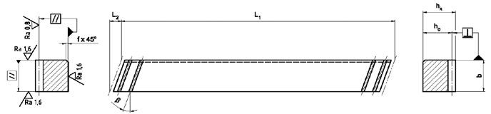
Tooth rack: Pressure angle α=20º ground, soft or hardened
Quality: f p (mm)
Outer surfaces: ground on all sides F p (mm)
4 in accordance with DIN 3962, 3963, 3967
Single pitch deviation
Module ≤ 3: 0.003
Module > 3: 0.004
Total pitch deviation F
0,015 for a 1000 mm Length
1) m Module 3) n Number of holes
2) z Number of teeth 4) ps Transverse pitch (p
any other lengths on request
Fig. 1
Fig. 2
Fig. 3
2.1.2 Module pitches Q5 helical toothed
Tooth rack: Pressure angle α=20º ground, soft or hardened
Quality: f p (mm)
5 in accordance with DIN 3962, 3963, 3967
Single pitch deviation
Module ≤ 3: 0.004
Module > 3: 0.005
Outer surfaces: ground on all sides F p (mm) Total pitch deviation
F p /1000 (mm) 0,024 for a 1000 mm Length
F p /2000 (mm) 0.032 for a 2000 mm length
Fig. 1
Fig. 2
Fig. 3
1) m Module 3) n Number of holes
2)
any other lengths on request
2.1 Standard gear racks
2.1.3 Module pitches Q6 helical toothed
Tooth rack: Pressure angle α=20º ground, soft or hardened
Quality: f p (mm)
6 in accordance with DIN 3962, 3963, 3967 Single pitch deviation
Module ≤ 3: 0.006
Module > 3: 0.008
Outer surfaces: ground on all sides F p (mm) Total pitch deviation F p /1000 (mm) 0,035 for a 1000 mm Length F p /2000 (mm) 0,045 for a 2000 mm Length
1) m Module 3) n Number of holes
any other lengths on request
Fig. 2
Fig. 3
2.1 Standard gear racks
2.1.4 Module pitches Q7 helical toothed
Tooth rack: Pressure angle α=20º ground, soft or hardened
Quality: f p (mm)
7 in accordance with DIN 3962, 3963, 3967
Single pitch deviation
Module ≤ 3: 0.007
Module > 3: 0.009
Outer surfaces: ground on all sides F p (mm) Total pitch deviation
F p /1000 (mm) 0.060 for a 1000 mm length
F p /2000 (mm) 0.075 for a 2000 mm length
1) m Module 3) n Number of holes
2) z Number of teeth 4) ps Transverse pitch (ps =m*π/cos β) β = 19.5283° (19°31’42”)
any other lengths on request
Fig. 1
Fig. 2
Fig. 3
2.1 Standard gear racks
2.1.5 Module pitches Q8 helical toothed
Tooth rack: Pressure angle α=20º milled, soft Quality: F
8 in accordance with DIN 3962, 3963, 3967 Total pitch deviation
1) m Module 3) n Number of holes
z
any other lengths on request
Fig. 1
Fig. 2
Fig. 3
2.1 Standard gear racks
2.1.6 Module pitches Q8 helical toothed
Tooth rack: Pressure angle α=20º ground, nitrided Quality: F p (mm) 9 in accordance with DIN 3962, 3963, 3967 Total pitch deviation
Outer surfaces: ground on all sides
1) m Module 3) n Number of holes
2) z Number of teeth 4) ps Transverse pitch (ps =m*π/cos β) β = 19.5283° (19°31’42”)
any other lengths on request
Fig. 1
Fig. 2
Fig. 3
2.1 Standard gear racks
2.1.7 Module pitches Q11 helical toothed
Tooth rack: Pressure angle α=20º milled, induction, hardened Quality: F p (mm)
11 in accordance with DIN 3962, 3963, 3967 Total pitch deviation
Outer surfaces: ground on all sides F p /1000 (mm) 0.220 for a 1000 mm length F p /2000 (mm) 0.330 for a 2000 mm length
1
2
3
any other lengths on request
Fig.
Fig.
Fig.
2.1.8 Module pitches Q4 straight toothed
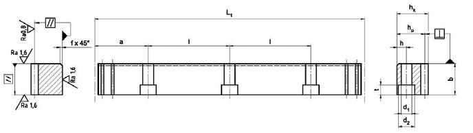
Tooth rack: Pressure angle α=20º ground, soft or hardened Quality: f p (mm) 4 in accordance with DIN 3962, 3963, 3967
Single pitch deviation
Module ≤ 3: 0.003
Module > 3: 0.004
Outer surfaces: ground on all sides F p (mm) Total pitch deviation F p /1000 (mm) 0.015 for a 1000 mm length
2.1 Standard gear racks 1)
any other lengths on request
Fig. 1
Fig. 2
Fig. 3
2.1 Standard gear racks
2.1.9 Module pitches Q5 straight toothed
Tooth rack: Pressure angle α=20º ground, soft or hardened Quality: f p (mm)
Outer surfaces: ground on all sides F p (mm)
5 in accordance with DIN 3962, 3963, 3967
Single pitch deviation
Module ≤ 3: 0.004
Module > 3: 0.005
Total pitch deviation
F p /1000 (mm) 0.024 for a 1000 mm length
F p /2000 (mm) 0.032 for a 2000 mm length
1) m Module 3) n Number of holes 2) z Number of teeth 4) p Pitch (p=m*π)
any other lengths on request
Fig. 1
Fig. 2
Fig. 3
2.1 Standard gear racks
2.1.10 Module pitches Q6 straight toothed
Tooth rack: Pressure angle α=20º ground, soft or hardened
Quality: f p (mm)
6 in accordance with DIN 3962, 3963, 3967
Single pitch deviation
Module ≤ 3: 0.006
Module > 3: 0.008
Outer surfaces: ground on all sides F p (mm) Total pitch deviation
F p /1000 (mm) 0.035 for a 1000 mm length
F p /2000 (mm) 0.045 for a 2000 mm length
1) m Module 3) n Number of holes
2) z Number of teeth 4) p Pitch (p=m*π)
any other lengths on request
Fig. 1
Fig. 2
Fig. 3
2.1 Standard gear racks
2.1.11 Module pitches Q7 straight toothed
Tooth rack: Pressure angle α=20º ground, soft or hardened Quality: f p (mm)
Outer surfaces: ground on all sides F p (mm)
7 in accordance with DIN 3962, 3963, 3967
Single pitch deviation
Module ≤ 3: 0.007
Module > 3: 0.009
Total pitch deviation
F p /1000 (mm) 0.060 for a 1000 mm length
F p /2000 (mm) 0.075 for a 2000 mm length
1) m Module 3) n Number of holes 2) z Number of teeth 4) p Pitch (p=m*π)
any other lengths on request
Fig. 1
Fig. 2
Fig. 3
2.1 Standard
2.1.12 Module pitches Q8 straight toothed
Tooth rack: Pressure angle α=20º milled, soft Quality: F p (mm) 8 in accordance with DIN 3962, 3963, 3967 Total pitch deviation
Outer surfaces: ground on all sides F p /1000 (mm) 0.150 for a 1000 mm length F p /2000 (mm) 0.225 for a 2000 mm length
any other lengths on request
Fig. 1
Fig. 2
Fig. 3
2.1 Standard
2.1.13 Module pitches Q9 straight toothed
Tooth rack: Pressure angle α=20º ground, nitrided Quality: F p (mm)
9 in accordance with DIN 3962, 3963, 3967 Total pitch deviation Outer surfaces: ground on all sides F p /1000 (mm) 0.180 for a 1000 mm length F p /2000 (mm) 0.270 for a 2000 mm length
any other lengths on request
Fig. 1
Fig. 2
Fig. 3
2.1 Standard gear
2.1.14 Module pitches Q11 straight toothed
Tooth rack: Pressure angle α=20º milled, induction hardened Quality: F p (mm) 11 in accordance with DIN 3962, 3963, 3967 Total pitch deviation
Outer surfaces: ground on all sides F p /1000 (mm) 0.220 for a 1000 mm length F p /2000 (mm) 0.330 for a 2000 mm length
any other lengths on request
Fig. 1
Fig. 2
Fig. 3
2.1 Standard gear racks
2.1.15 Q6 metric pitch, straight toothed
Tooth rack: Pressure angle α=20º ground Quality: f p (mm)
Outer surfaces: ground on all sides F p (mm)
6 in accordance with DIN 3962, 3963, 3967
Singlel pitch deviation
Module ≤ 3: 0.006
Module > 3: 0.008
Total pitch deviation F p /1000 (mm) 0.035 for a 1000 mm length
Tooth rack: Pressure angle α=20º ground Quality: f p (mm) 6 in accordance with DIN 3962, 3963, 3967
Single pitch deviation
Module ≤ 3: 0.006
Module > 3: 0.008
Outer surfaces: ground on all sides F p (mm) Total pitch deviation
Material: X90CrMoV18 F p /1000 (mm) 0.035 for a 1000 mm length
1) m Module 3) n Number of holes
2) z Number of teeth 4) p Pitch (p=m*π)
any other lengths on request
Fig. 1
Fig. 2
Fig. 3
2.2 Customised gear racks
2.2.1 Customised gear racks
Any gear racks and guide racks can be made to a customer's drawing as long as they are within the specifications listed below.
Unit weight:
max. 500 kg
Length: max. 3000 mm
Tooth rack:
Helix angle β:
Material:
Modules 2 20
Metric 5 mm 20 mm
-30° …+30°
Left and right ascending
C45, 42CrMo4+QT, 16MnCr5
X90CrMoV18 (stainless steel)
Hardening process: Induction hardening
Case hardening
Through hardening
Nitriding
Best accuracy: Q4
Combination with profiled linear guideway
Screw connection from below
Box way with integrated tooth rack
Screw connection through the tooth rack
Gear rack integrated into linear bearing (guide rack)
3 Installation
3.1 Gear racks fitting instructions / lubrication
Gear racks can be assembled in any lengths. When assembling the spacing between two gear racks must be pitch precise. Dowels may be needed for gear racks shorter than 1m.
• Aligning the first gear rack
• Tighten the screws with a torque wrench.
• The torque depends on the friction condition and strength class of the screws.
• For soft or induction hardened gear racks use screws with a strength class of 10.9. For case and through hardened gear racks use strength class 12.9.
• Align the next gear rack with a mounting plate.
• Screw the gear rack on.
• Using a measuring roller check the height deviation at the transition point and if necessary change the position of one gear rack.
• Check that the gear racks are parallel to each other.
• Finally, insert the pins if necessary.
Lubrication - instructions for use
Adequate lubrication using a lubricant adapted to the operating conditions is required to maintain the functionality of the rack drive. Lubrication protects from wear and corrosion and reduces friction.
Apart from the initial lubrication during assembly, the machine must be lubricated regularly during operation.
Normally electrically-driven lubrication cartridges are used for lubrication. Lubrication greases NLGI 00 to NLGI 0 are applied to the drive pinion or the gear rack with a felt pinion.
A typical lubricant is Klüber Microlube GB 0.
Too little lubrication shortens the service life of the drive system. Therefore, always ensure that the machine is lubricated adequately.
The detailed version of our mounting instruction is available under www.schneeberger.com/downloads.
4 Order description
4.1 Standard gear racks
Standard gear racks
Quantity
Model ZST
Tooth rack M modular T ___ metric, in mm
Size b x hk x L1 in mm
Tooth rack S inclined to the right, 19.5283°
G straight
Hardness
C Material 16MnCr5, case hardened
I Material C45, induction hardened
W Material C45, soft
N Material 42CrMo4+QT, nitrided
V Material 42CrMo4+QT, tempered
H Material X90CrMoV18 (stainless steel), through hardened
Accuracy 4, 5, 6, 7 ground
8 milled, soft
9 ground, nitrided
11 milled, induction hardened
Drilled holes D with pin and fixing holes
OP without pin holes
OH without holes
Standard assembly tool
Quantity
Model MST
Tooth rack M modular T ___ metric, in mm
Grösse b x hk x L1 in mm
Tooth rack SL inclined to the left, 19.5283°
G straight
Fig. 1
Fig. 2
Fig. 3
4. Order description
4.2 Customised gear racks
Customised gear racks
Quantity
Model ZST
Tooth rack M modular
T ___ metric, in mm
Size
Tooth rack
b x hk x L1 in mm
S inclined to the right
SL inclined to the left
G straight
Hardness C Material 16MnCr5, case hardened
O Material 16 MnCr5, nitrided
I Material C45, induction hardened
W Material C45, soft
M Material 42CrMo4+QT induction hardened
N Material 42CrMo4+QT, nitrided
V Material 42CrMo4+QT, tempered
H Material X90CrMoV18 (stainless steel), through hardened
GREAT BRITAIN +44 74 63 89 85 08 info-uk@schneeberger.com
PROSPECTUSES
COMPANY BROCHURE CUSTOMIZED BEARINGS GEAR RACKS
Linear bearings and Recirculating units MINERAL CASTING SCHNEEBERGER MINISLIDE MSQscale
MINI-X MINIRAIL / MINISCALE PLUS / MINISLIDE MONORAIL and AMS profiled linear guideways with integrated measuring system MONORAIL and AMS application catalog POSITIONING SYSTEMS
A.MANNESMANN A member of SCHNEEBERGER linear technology