MONORAIL and AMS
Profiled linear guideways and integrated measuring systems | Technical Information
Mounting Instructions

5.6 Preparing

Profiled linear guideways and integrated measuring systems | Technical Information
Mounting Instructions
5.6 Preparing
The MONORAIL and AMS installation instructions describe how to install the MONORAIL MR and MONORAIL BM profiled linear guideway systems and the integrated AMS distance measuring system.
These installation instructions are intended for installers, service technicians, and all personnel who install, operate, replace, handle, or transport MONORAIL profiled linear guideways and AMS distance measuring systems and who have read and understood these instructions.
1. This is the first step of a multi-part action prompt.
2. This is the second step of a multi-part action prompt.
Ș This is a result.
• This is a bullet point.
Notes and recommendations are set out here.
Warning notes are placed before working steps that give rise to a potential danger. Warning notes are classified as follows, in accordance with the keyword, the type and source of the danger, the possible consequences should the danger be realised and/or the warning note be disregarded, and the measures to be taken to avoid the danger;

A danger is present that involves a high degree of risk. Disregarding this note will result in death or serious injury.
A danger is present that involves a medium degree of risk. Disregarding this note may result in death or serious injury.
A danger is present that involves a low degree of risk. Disregarding this note may result in minor or moderate injury.
A possibly harmful situation is present that could result in damage to the product or an item in its vicinity.
These installation instructions should be read carefully prior to installation in order to avoid potential danger and/or damage.
When installing the MONORAIL and AMS systems, the general safety instructions, warning notes, and installation notes in these instructions should be followed as precisely as possible.
Please do not hesitate to contact SCHNEEBERGER should you require any further information.
The MONORAIL and AMS systems should be installed by appropriately qualified or trained specialists, e.g. by installers who have read and understood these instructions.
MONORAIL and AMS are components for precise linear movement and distance measurement.
MONORAIL and AMS must only be operated within the intended temperature ranges (MONORAIL -40°C to +80°C, AMS 0°C to +70°C).
SCHNEEBERGER profiled linear guideways must not be used as safety components.
SCHNEEBERGER assumes no liability for damage arising from the following:
• Improper handling, installation, and/or maintenance
• Improper use of the guideways and/or distance measuring system
• Arbitrary modifications to MONORAIL and AMS
In extreme cases – for example, in the event of the loss of rolling elements –carriages may become separated from the rail. It should be checked prior to each use whether a risk of personal injury exists in this case and any such risk excluded using suitable design measures.
Danger to life posed by falling carriages!
Carriages may become separated from the guide rail and fall in the event of overloading or the loss or rolling elements.
• All maintenance and conversion procedures on parts subject to wear must be carried out in a load-free state.
• Additional fall protection must be applied.
• Design measures must be implemented to prevent individuals from accessing the movement zones of the axis slides.
• MONORAIL and AMS are used in conjunction with heavy loads that may only be lifted, installed and transported using a suitable lifting device together with an adequate number of personnel.
• MONORAIL and AMS must be stored in their original packaging prior to installation and protected from moisture and damage.
• MONORAIL AMS must be protected from magnetic fields. These could destroy the magnetic measuring scale in the event of direct contact.
• Disconnect the power supply prior to any work on electrical equipment.
• Only use original SCHNEEBERGER parts for repair work.
• Comply with all country-specific regulations, standards, and guidelines for accident prevention.
• To ensure the proper functioning of the products, also observe the instructions on profile and position tolerances, dynamic limits, load, lubrication, and environmental conditions.
2.4 Environmentally responsible conduct
Do not allow lubricants and electronic components to be released into the environment, and ensure that these are disposed of in accordance with country-specific regulations.Product information
MONORAIL is a profiled linear guideway system. It consists of a single guide rail with accompanying carriages (MONORAIL guideway) or multiple associated MONORAIL guideways (MONORAIL system).
In the case of MONORAIL AMS with integrated distance measuring system, the guide rail is equipped with a magnetic measuring scale and one or more carriages on the guide rail is equipped with a housing with a read head.
MONORAIL is available in the following product versions:
Roller-MONORAIL MR
Profiled linear guideway with rollers as rolling elements
Ball-MONORAIL BM
Profiled linear guideway with balls as rolling elements
Ball-MONORAIL BM WR / BM SR
Profiled linear guideway in a stainless steel design with balls as rolling elements
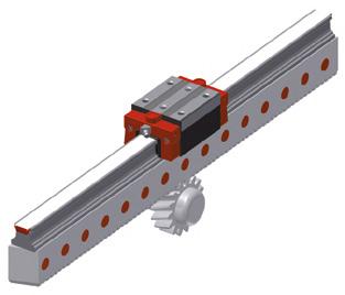
MONORAIL BZ
Ball-profiled linear guideway with integrated tooth rack
MONORAIL AMSA 3B
Roller-profiled linear guideway with distance measuring system with incremental analogue interface
MONORAIL AMSD 3B
Roller-profiled linear guideway with distance measuring system with incremental digital interface
MONORAIL AMSA 4B
Ball-profiled linear guideway with distance measuring system with incremental analogue interface
MONORAIL AMSD 4B
Ball-profiled linear guideway with distance measuring system with incremental digital interface
MONORAIL AMSABS 3B
Roller-profiled linear guideway with distance measuring system with absolute interface
MONORAIL AMSABS 4B
Ball-profiled linear guideway with distance measuring system with absolute interface
MONORAIL AMSABS DC 3B
Roller-profiled linear guideway with distance measuring system with absolute DRIVE-CLiQ interface
MONORAIL AMSABS DC 4B
Ball-profiled linear guideway with distance measuring system with absolute DRIVE-CLiQ interface
MONORAIL AMSA 3L
Ball-profiled linear guideway with distance measuring system for multi-part rails with incremental analogue interface
MONORAIL AMSABS 3L
Rolled profiled linear guideway with distance measuring system for multipart rails with absolute interface.
DRIVE-CLiQ is a registered trademark of
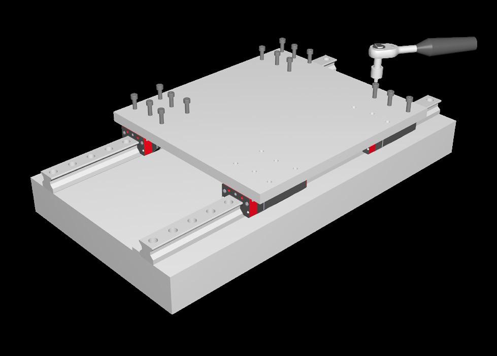
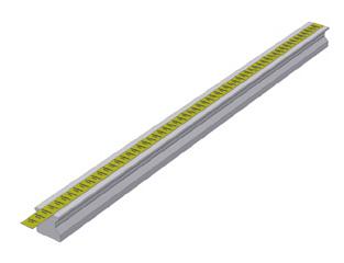
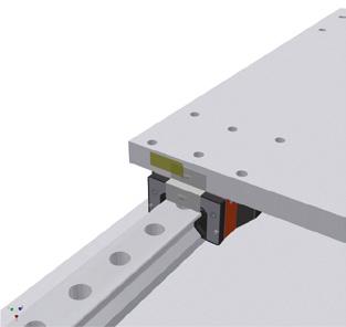
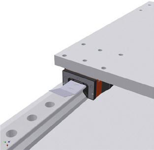
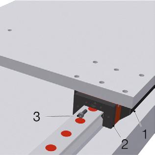
The following figures show the components of a MONORAIL guideway system with AMS based on the example of MONORAIL AMSA 3B.
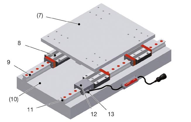
system The mounting plate (7) and the machine bed (10) are not included in delivery.
system
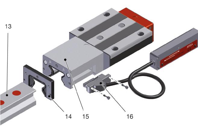
13 Guide rail with magnetic measuring scale
14 Additional wipers
15 AMS carriage
16 Sensor unit
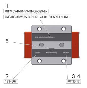
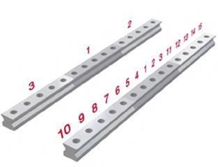
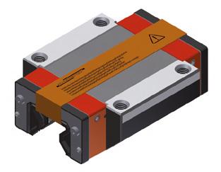
SCHNEEBERGER labels guide rails and carriages distinctly so that products can be identified and tracked at any time. The labelling includes a precise type designation, the date of manufacture and, in the case of guide rails, a serial number.
In the case of multi-part guide rails and cover strips, the individual segments and joints are also labelled to enable installation of the individual components in the correct order.
Carriages are labelled on their upper side between the polished mounting surfaces. The label consists of the following information:
1 Type description (for codes, see MONORAIL and AMS product catalogue)
2 Production order No.
3 Calendar week of production
4 Production year
5 Optional: Designation of carriage differing from standard version
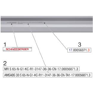
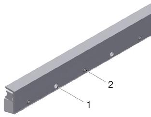
Guide rails
Guide rails are labelled at the profile base opposite the locating side. The label consists of the following information:
1 SCHNEEBERGER company logo
2 Type description (for order codes, see MONORAIL product catalogue)
3 Consecutive serial number
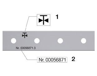
AMS guide rails with magnetic measuring scale
Guide rails with magnetic measuring scale are labelled at the profile base opposite the measuring scale, and are also marked on the upper surface of the rail with the serial number and a label for reference mark type. The label is located on the same side as the measuring scale.
1 Sign for reference mark pattern (for codes, see following table)
2 Serial number
The following reference mark types are available:

Equidistant reference mark spacings
Matched and multi-part guide rails
AMSA 3B/4B
AMSD 3B/4B
AMSA 3L 25
AMSA 3L 35
AMSA 3L 45
AMSA 3L 55
AMSA 3L 65
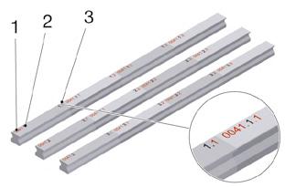
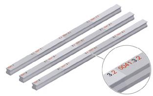
Matched guide rails are marked with a consecutive serial number on the rail upper surface. Multi-part guide rails are also marked at each butt joint using a joint numbering system. The numbering consists of:
1 Set number (consecutive)
2 Rail line number (consecutive for each rail set)
3 Joint indicator serial number (consecutive for each line)
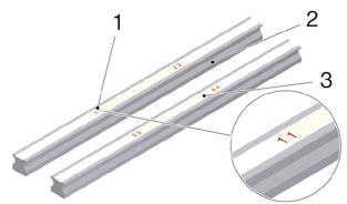
Multi-part cover strips are labelled at the butt joint with a joint indicator serial number. This is located at the end of each strip on its underside:
1 Joint indicator serial number (consecutive for each rail set)
2 Rail line 1
3 Rail line 2
3.4
Product identification - measuring system
The MONORAIL AMS distance measuring system is available in six versions:
• AMSA
• AMSD
• AMSABS
• AMSABS DC
• AMSA 3L
• AMSABS 3L
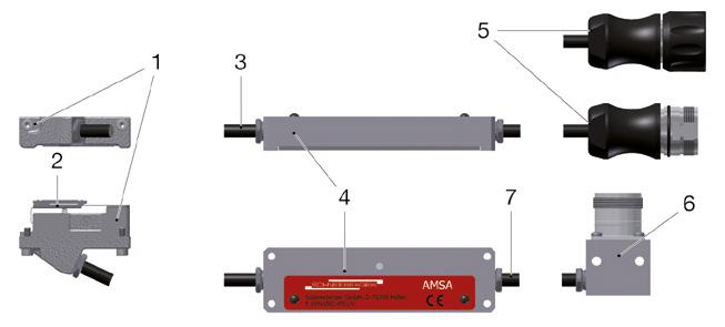
With the exception of AMSA 3L, these are available both for Ball MONORAIL BM and for Roller MONORAIL MR. Each distance measuring system can be identified by its electronics housing.
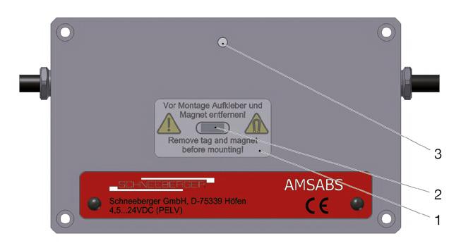
The labelling on each electronics housing includes the following information:
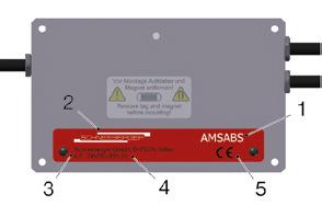
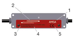
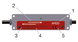
1 Type designation
2 SCHNEEBERGER GmbH company logo
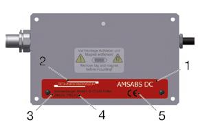
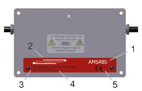
3 Address of SCHNEEBERGER GmbH (Höfen)
4 Input voltage specification
5 CE marking
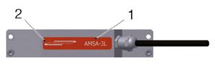
An exception is the AMSA 3L measuring system. In this case the identifying label is located directly on the read head.
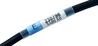
Article name and serial number can be found on the cable nearby the connector. For AMSABS DC nearby the electronics box
MONORAIL guideways and the AMS distance measuring system are highprecision components which must be handled with appropriate care. The following instructions should be followed to prevent damage during storage and transportation:
• Internal transportation should only be carried out by trained personnel.
• Where possible, guideways and accessories should be stored and transported in their original packaging to protect them against corrosion.
• Do not store products outdoors and protect them from impact damage and moisture.
• We recommend storage in packaging corresponding to the original condition. High humidity and extreme temperatures and temperature fluctuations must be avoided. Otherwise there is a risk of condensation, corrosion and possibly separation of the grease into thickener and oil.
• Only remove the products from their original packaging at their installation location and immediately prior to assembly.
The packaging supplied affords the products sufficient protection against damage during proper transportation, and will protect them from corrosion resulting from fluctuations in humidity and temperature for a period of eight weeks.
The products must be checked for damage and corrosion every eight weeks. Where necessary, they should be cleaned and freshly packaged using a suitable corrosion inhibitor.
The MONORAIL products will be dispatched either in individual cardboard boxes, in wooden crates, or on pallets containing several packaged items. The packaged items may measure over 6 m in length. In the case of cardboard packages from a gross weight of 30 kg upwards, disposable or returnable pallets are placed underneath them to make them easier to stack. Where a package length exceeds 1.50 m, boards are also placed beneath the cardboard boxes for reinforcement to prevent excessive sagging.
• Long packaged items must be lifted from their centre of gravity at the mid-point of the package.
• Wooden crates may be stacked to a maximum height of three on top of one another.
• Pallets with cardboard boxes may not be stacked.
Auxiliary tools
Any suitable lifting devices may be used to move individual carriages, rails, or packaged items that do not pose a risk of bending the rails or causing other damage to the products.
• The lifting device must not damage the products or their packaging.
• The lifting device must minimise the amount of deflection.
Guide rails
WARNING!
Risk of injury posed by improper transportation!
Rails may fall during transportation and cause injury to persons nearby.
• Suspend long rails at several points with a crane during transportation.
• The slewing range of long rails must be taken into consideration.
Risk of injury posed by escaping carriages!
Carriages may become detached from the guide rail during transportation.
• Never position guide rails with carriages at an incline during transportation or handling.
Guide rails must be supported over their entire length during storage.
Cover strips
Risk of injury posed by sharp-edged cover strips!
Cover strips may have sharp edges which can cause cutting injuries when touched.
• Protective gloves should be worn during cover strip installation.
• Where possible, cover strips should be stored and transported rolled up in their original packaging.
• Straight strips should be supported across their full length and not allowed to bend.
• Observe the minimum bending radius of the strips (Rmin 0.4 m).
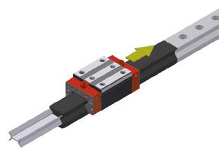
To prevent the loss of rolling elements, ensure that the carriages are protected from impact loads.
• For the protection of rolling elements, always store and transport carriages on the guide rail or on a transport or assembly rail.
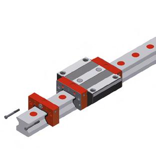
Risk of material damage posed by mounting carriages onto the guide rail using a transport rail!
Mounting carriages onto the guide rail using a transport rail may cause rolling elements to fall out.
• Do not use transport rails for carriage installation.
• Mount carriages onto the guide rail using an MRM or MBM assembly rail, see also „Replacing defective components“ on page 60.
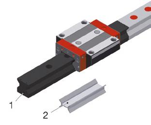
1 Assembly rail
2 Transport rail
The MONORAIL BZ system is fitted with an aluminium L profile for improved transportation safety and handling. The BZ is packaged in wooden crates together with wooden inserts that protect the guide rails from tipping over and slippage. All steel parts are treated with a corrosion inhibitor and packaged in VCI film. Following successful system installation, the aluminium profile is disassembled and can be disposed of. It is possible to arrange a return consignment for recycling with SCHNEEBERGER GmbH on a case by case basis which may contain all installation components where applicable.
Measuring system
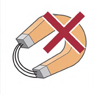
Risk of material damage posed by magnetic fields!
The magnetic scale of the AMS guide rails may be destroyed in the event of direct contact with magnetic fields.
• Protect rails with integrated scale from magnetic fields.
• Do not use lifting magnets for transportation.
• Protect read heads from strong vibrations or impacts.
• Where possible, always transport read heads installed in their housing. Only remove read heads from their housing in order to mount carriages onto guide rails.
• Always disassemble the read head before mounting carriages.
• During storage: In the case of the AMSABS measuring system, do not remove the activation strip on the power supply on the electronics housing (see „Preparing the measuring system for installation“ on page 18). Only activate the battery during commissioning.
5.1
Installing MONORAIL MR/BM/BZ
• MRM assembly rails for MONORAIL MR or MBM for MONORAIL BM
• Oil stone and polishing pad
• Suitable solvent (e.g. white spirit)
• Lubricating oil or lubricating grease
• Grease containing MoS2 for the fastening screws, in order to ensure consistent and therefore optimal screwing forces
• Torque wrench
• MWM installation carriage for MONORAIL MR
• Fastening screws for the guide rails
• Spanner, screwdriver, and Allen wrench for the installation of lubricating accessories and additional wipers
• Soft cloth
• Corrosion protection
Additional for installation of MRK/BRK plastic plugs
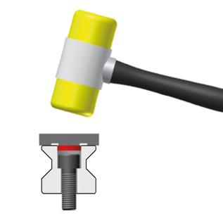
• Plastic hammer and spacer
Additional for installation of MRS/BRS brass plugs
• MWH/BWH hydraulic assembly tool and MZH hydraulic cylinder incl. hydraulic unit
• Scalpel, brass brush, and compressed air pistol for installation
• Portable drill, thread cutter, drill, centre punch, and a screw with hexagonal socket (e.g. DIN 912/ISO 4762) for dismantling
Additional for installation of MRZ steel plugs
• MWH/BWH hydraulic assembly tool and MZH hydraulic cylinder incl. hydraulic unit
• Portable drill, thread cutter, drill, centre punch, and a screw with hexagonal socket (e.g. DIN 912/ISO 4762) for dismantling
Additional for installation of MAC / BAC cover strip
• MWC or BWC assembly tool for installation
• Flat-tipped screwdriver and small Allen wrench for dismantling
Cardboard packaging is used for individual guide rail deliveries and system deliveries. Wooden crates are available for certain countries or special requirements for an additional fee. These are IPPC (International Plant Protection Convention) treated.
The carriages are individually packaged in cardboard boxes. Carriages and rails are wrapped in VCI film prior to delivery in all cases to protect them against corrosion. Systems are delivered using inserts made from corrugated cardboard (for delivery in cardboard packaging) or maritime pine slabs (for delivery in wooden crates). Accessories and lubricating accessories are enclosed.
Individual packaging
All guideway components are delivered unassembled in individual packaging. Accessories are included in a separate package.
Unless otherwise specified by the customer, all standard lube connections are opened and closed with set screws (S99/S98). Lube connections that are not required for use are closed.Individual carriages are delivered on a transport rail to protect the rolling elements.
AMS measuring systems are installed ready to plug-in, and electrical accessories and cables are packaged together with the mechanism. In its delivered condition the read head can be either installed in its housing or separately packaged as an individual component.
A system delivery means that the carriages are mounted with all accessories and enclosed with the guide rail in the same package. Lube connections on the carriages are prepared according to the customer’s specifications. Lubricating accessories are installed as specified or supplied in separate packaging. In the case of AMS systems, the carriages are mounted with all accessories and installed onto the guide rail.
The external surfaces of the carriages and of the rails are treated with a hardening corrosion protection. The rolling elements are given a mineral-oil-based corrosion protection. Grease protection can also be provided upon request. Carriages and rails are wrapped in a VCI film. Additional precautions are taken for special requirements such as overseas transport.
Risk of material damage posed by improper unpacking!
Incisions in the groove base of the distance measuring system can damage the measuring scale.
• Only cut at the upper or underside of the rails.
• Never make cuts in the groove base.
Risk of material damage posed by premature unpacking!
Read heads can be damaged by premature unpacking.
• Only remove individually packaged read heads from their packaging immediately prior to installation.
• Unpack profiled linear guideways (including with integral distance measuring system) at the installation location directly prior to installation. Carefully cut open the corrosion protection film using a commercially-available film cutter and without scratching parts of the guideway.
• Special care must be taken in the case of guide rails with an integrated distance measuring system to ensure that cuts are only made at the upper and undersides of the rails and never in the groove base, as this is where the measuring scale is located.
• Always support long guide rails at several points of contact during handling.
• Always keep carriages on the guide rail where possible. Always leave individually packed carriages on the transport rail.
• Use an MRM or MBM assembly rail for mounting carriages onto and dismounting them from the guide rail. Once dismounted, keep carriages on the assembly rail.
• Check the parts delivered for completeness and condition. Take particular care to check that cover strips, lube connection parts, gaskets, plugs etc are not bent.
• Store delivered parts prior to installation in order to achieve temperature equalisation. Read installation notes and accompanying product documentation carefully before installation.
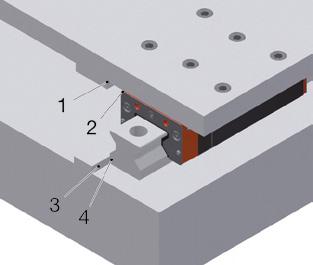
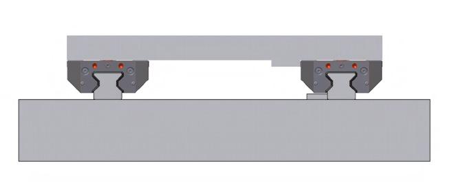
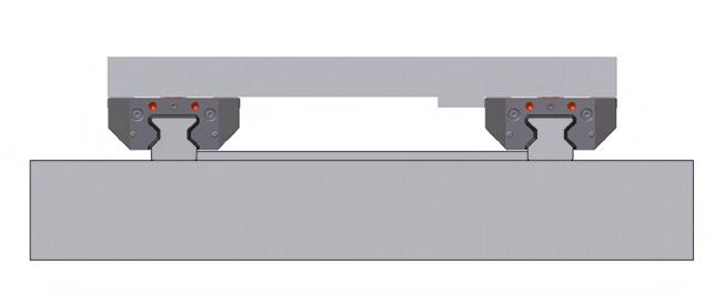
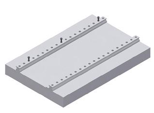
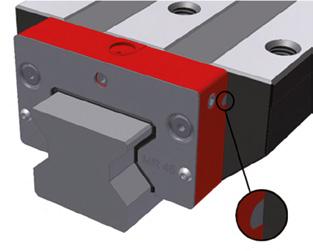
5.6 Preparing the locating surfaces
The locating surface of the rails can be found on the side facing away from the SCHNEEBERGER and type number labels.
1 Mounting plate locating surface
2 Carriage locating surface
3 Machine bed locating surface
4 Guide rail locating surface
The locating surfaces are prepared as follows:
1. Check the locating surfaces of the machine bed and mounting plate for shape and positional accuracy. Rework the locating surfaces if these do not meet the specifications.
2. Clean all locating surfaces thoroughly. Remove ridges and surface irregularities with an oil stone.
3. Ensure prior to and during installation that the guideways and mounting base are at the same temperature.
4. Remove the corrosion protection from guide rails and carriages using a suitable solvent, e.g. white spirit. Do not use any solvents capable of damaging plastics. Do not move carriages during this time, as this could result in damage.
Risk of material damage posed by movement of carriage! This can result in material damage.
• Never move carriages during use of a corrosion protection or suitable solvents.
5. Lightly oil the locating surfaces of the guide rails and carriages.
5.7 Preparing the measuring system for installation
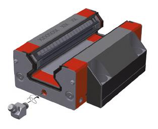
The absolute distance measuring system has an integrated battery-assisted power supply which ensures that the position information is retained even if the controller is switched off.
The measuring system is prepared as follows:
1. Unpacking
2. Remove the cover plate from the housing see 6.5.2 „Installing and connecting the read head“ auf Seite 25.
3. Activate the power supply:
• Remove the activation strip together with the magnet beneath it from the electronics housing (see figure).
Ș The LED flashes red briefly or stays off (depending on the battery's charging status).
4. Install the read head.
Ș LED lights up green briefly. when the read head is referenced.
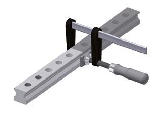
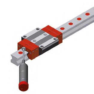
6.1 MWM Installation carriage
The installation carriage can be used to carry out the following installation work:
Alignment of the butt joints in the case of multi-part guide rails
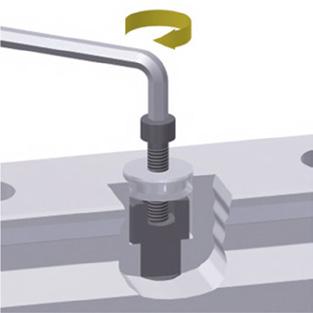
1. Position the carriage over the joint so that one of the two external fixing holes of the guide rail is visible.
2. Position the carriage over the fixing hole of the other guide rail and insert and tighten the screw.
Adjusting the guide rails without lateral reference
1. Pass the installation carriage gradually over the guide rail.
Ș The lateral position is measured by laser or dial gauge.
2. Place the carriage over the central guide rail fixing hole.
3. Press the rail into the desired position.
4. Introduce guide rail fastening screws into the guide rail from above via the central fixing hole and tighten.
The installation carriage is available from SCHNEEBERGER as an accessory.
Risk to life posed by falling machine elements!
Possible consequences include death and serious injury.
• Ensure that additional fall protection is provided.
• Never remove the front plate from MONORAIL BM.
• Rolling elements must under no circumstances be allowed to fall out of the carriage.
• In order to prevent rolling element loss, always store and transport carriages on transport/assembly rails.
• Always keep carriages on the guide rail. Mount carriages onto and dismount them from the transport rail using an assembly rail.
• If optionally implementing paired systems, ensure that the carriages of different guide rails are not interchanged.
• In the case of carriages with a read head, always remove the read head before mounting the carriage onto an assembly rail.
• Protect individual carriages from dirt and the loss of rolling elements.
• Always brace the locating surfaces of the carriage against the locating surfaces of the mounting plate. The locating surface of the carriage is the side that has been ground.
• Arrange for reworking of front plates to alter the lube connection to be carried out through SCHNEEBERGER.
• Before mounting carriages onto the guide rail, remove the factory-applied protective coating. In the case of repeated movement of the carriages back and forth on the guide rail, protect wipers from damage caused by sharp-edged rail fixing holes.
• Always tighten fastening screws using a torque wrench (for tightening torques, see „Screw tightening torques“ on page 75
In the case of Monorail MR 100, a metal transport rail is used.
This must be replaced prior to installation using an assembly rail, in accordance with the following procedure:
• The transport rail must be pushed out of the carriage using the assembly rail.
• Removal of the transport rail without replacement with an assembly rail may result in the loss of rolling elements.
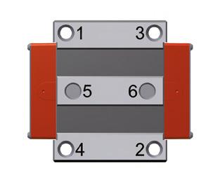
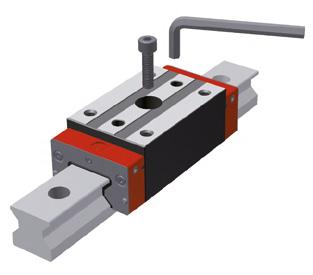
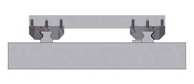
When fastening a connecting structure to a carriage, tighten the screws in accordance with the following steps:
• Tighten the screws with 50 % of the nominal torque. See numbering for sequence.
• Tighten the screws with 100 % of the nominal torque. See numbering for sequence.
Ensure prior to installation that the guide rails, machine bed, mounting plate, and fastening screws are all at the same temperature.
Always brace the locating surface of the guide rails against the locating surface of the machine bed. The locating surface of the guide rails is the surface on the opposite side of the SCHNEEBERGER logo and part numbering.
For optimal screwing force, proceed as follows:
1. Lubricate the screw head rests and threads of the fastening screws with grease containing MoS2.
2. Tighten the fastening screws in accordance with the figure on the left.
3. Always tighten fastening screws using a torque wrench (for tightening torques, see „Screw tightening torques“ on page 75.
6.4 Handling multi-part guide rails
Multi-part guide rails are marked with a number at their joints. In the case of a matched design, the guide rails are also marked with a set number at the start of the rail. The guide rail with the set number index 1, or with the butt joint number 1 is designated as the reference rail.
Installation procedure:
• Install individual rail segments alternately or consecutively from the line centre outwards.
• Install the guide rails so that the butt joint numbers match.
Proceed as follows according to the rail system:
• In the case of multi-part rails without a locating surface in the machine bed, align the butt joints using a fixing bridge or MWM installation carriage.
• In the case of guide rails with locating surfaces on the machine side, lay the guide rails with their locating side against the locating surface.
• In the case of MONORAIL AMS, install the guide rail with the magnetic measuring scale as the reference rail. MONORAIL AMS guideways have a designation on the guide rail and a carriage with a read head.
Risk of material damage posed by sharp edges!
Carriage cross wipers can be damaged during operation by sharpedged rail fixing holes.
• Ensure that rail fixing holes are covered.
Prior to carriage installation, cover the mounting holes on the upper surface of the guide rail with a suitable adhesive tape. The adhesive tape protects the cross wiper of the carriage from damage by sharp-edged fixing holes.
6.5
Handling measuring systems
Failure to observe the points specified in this section may result in material damage.
ATTENTION!
Risk of material damage posed by magnetic fields! Incorrect handling of AMS rails in relation to magnetic fields may result in material damage.
• Observe the points in the following section.
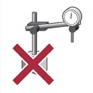
(Fig. 26). Only non-magnetic materials should be used in the direct vicinity of the measuring scale and the read head.
(Fig. 27) Only use non-magnetic aids to transport and align AMS guideways.
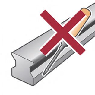
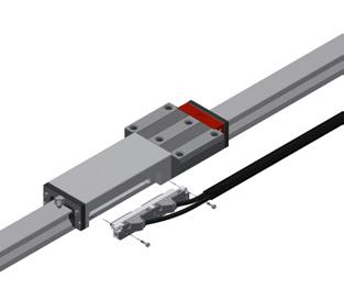
(Fig. 28) Avoid direct contact between tools and the magnetic measuring scale.
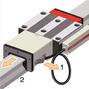
(Fig. 29) Disassemble the AMS read head (1) before mounting or dismounting the MONORAIL carriage onto or from the guideway (2).
ATTENTION
Risk of material damage posed by incorrect insertion of read head! May result in damage to sliding parts.
• Do not allow any particulates to become caught between the sensor slider and the scale.
• Do not allow sliding parts to come into contact with the read head.
• Do not damage the sliding parts.
Installing the read head (Fig. 30) In the case of MONORAIL AMS systems delivered without a read head, the housing is sealed with a cover plate (1). This must be removed prior to read head installation.
Screws: 2x ISO 4762 M3x10 - A2 (self-locking) 2x ISO 4762 M2.5x10 - A2 (self-locking) 2x ISO 4762 M4x20-A2 2x ISO 4762 M3x10 - A2 (self-locking) 1x ISO 4762 M3x4 - A2 (self-locking) 2x ISO 4762 M3 x 10 - A2 (captive)
ning torques
Connecting the read head
ATTENTION
Risk of material damage posed by short-circuit currents! The electronics in the read head are vulnerable to destruction by short-circuit currents.
• Before connecting the cable, disconnect the power supply and ensure that it cannot be restored without authorisation.
Connecting directly to the drive controller: Connect the read head plug to the drive controller and tighten the swivel nut by hand.


6.5.3 Installing product versions AMS 3B, AMS 4B, and AMSA 3L
1. Where necessary, remove the cover plate from the housing.
2. Carefully insert the read head into the lateral recess of the housing.
3. Insert and tighten the fastening screws. No additional adjustment is necessary. The tightening sequence is irrelevant in this case.
6.5.4 Installing product version AMSABS 3B, AMSABS 4B
1. Where necessary, remove the cover plate from the housing.
2. Activate the battery, see 5.7 Preparing the measuring system for installation on page 17
3. Carefully insert the read head into the recess in the housing using a rotating motion.
4. Swivel the distance reference cover plate (1) for mounting.
5. Slide the read head (2) towards the carriage until it stops and hold it down (see Figure). This ensures that the measuring system automatically recognises its absolute position during installation and is ready to use immediately afterwards. Once the controller is switched on, the LED will light up green.
6. Swing the distance reference cover plate (1) to the designated position and hold it down.
7. The sensor unit is delivered with self-locking screws. Tighten these in accordance with the torque values (see „Installing and connecting the read head“ on page 25). Tighten the screws in the following order: A, B, C (Fig. 33).
6.5.5 Mounting product variant AMSABS 3L
1. Remove the cover plate on the add-on housing, if necessary.
2. Activate the battery (see "5.7 Preparation for mounting the measuring system" on page 17).
3. Carefully insert the read head into the recess on the side of the add-on housing.
4. Insert and tighten the fastening screws. Additional adjustment work are not necessary. The order in which the screws are tightened is irrelevant.
6.6 Installation options
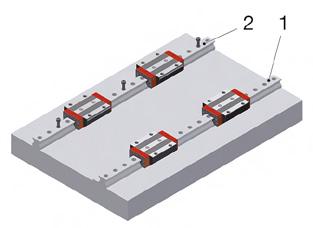
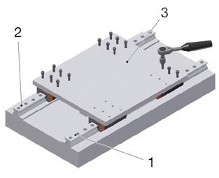
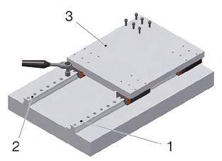
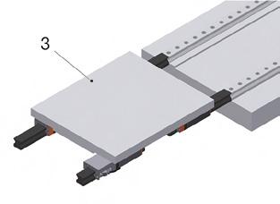
6.6.1 Installation option 1
Installation option 1 is applicable in cases in which locating surfaces are present for one guide rail and for one carriage.
1. Brace the reference rail (1) against the locating surface of the machine bed and fasten with screws (see „Handling guide rails“ on page 21).
2. Adjust the opposite guide rail (2) so that it is parallel and pre-fasten it by lightly tightening its screws.
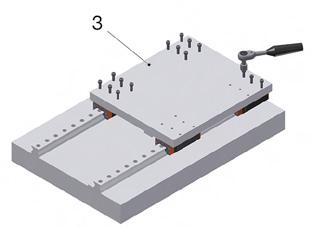
3. Place the mounting plate (3) on the carriage and lightly tighten its fastening screws.
4. Brace the mounting plate (3) against the locating surfaces on the carriages on the secured reference rail and fasten its screws.
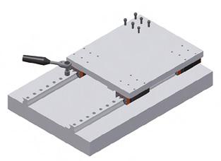
5. Fasten one carriage on the pre-fastened guide rail to the mounting plate (3) with screws.
6. If carriages with additional wipers are protected by an installation protection film: prevent the protective film from slipping see "Removing the protective installation film for additional wipers (optional)" on page 49.
7. Slide the mounting plate (3) with carriages back and forth. Tighten the fastening screws of the unsecured guide rail tightly against the carriage (see „Handling guide rails“ on page 21).
8. Fully fasten the mounting plate (3).
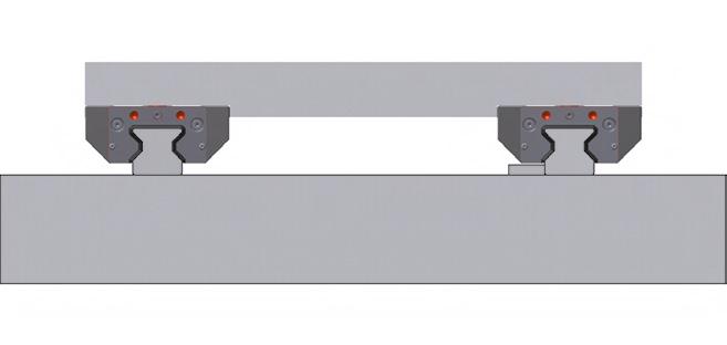
6.6.2 Installation option 2
Installation option 2 is applicable in cases in which locating surfaces are present for both guide rails and for one carriage.
1. Brace both guide rails (1), (2) against the locating surfaces and fasten with screws (see „Handling guide rails“ on page 21).
2. Install clamping screws or clamping or wedge bars where required.
3. Place the mounting plate (3) on the carriages and lightly tighten all fastening screws.
4. Brace the mounting plate (3) against the locating surfaces of the carriages on the reference rail and fasten to both carriages.
5. If carriages with additional wipers are protected by an installation protection film: prevent the protective film from slipping (see „Removing the protective installation film for additional wipers (optional)“ on page 50).
6. Slide the mounting plate (3) with carriages once over the full length of the guide rails.
7. Fully fasten the mounting plate (3).
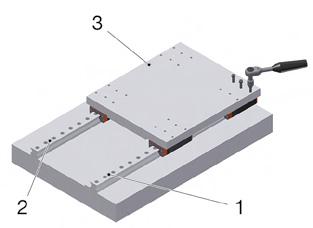
6.6.3 Installation option 3
Installation option 3 is applicable in cases in which locating surfaces are present for one guide rail and for both carriages.
1. Brace the reference rail (1) against the locating surface and fasten with screws (see „Handling guide rails“ on page 21).
2. Adjust the opposite guide rail (2) so that it is parallel and pre-fasten it.
3. Place the mounting plate (3) on the carriages and lightly tighten its fastening screws.
4. Brace the mounting plate (3) against the locating surfaces of the carriages on the rails on each side and fasten with screws.
5. If carriages with additional wipers are protected by an installation protection film: prevent the protective film from slipping (see „Removing the protective installation film for additional wipers (optional)“ on page 50).
6. Install clamping screws or clamping or wedge bars where required.
7. Slide the mounting plate (3) with carriages back and forth and tighten fastening screws on the unsecured guide rail tightly against the carriage (see „Handling guide rails“ on page 21).
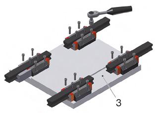
6.6.4 Installation option 4
Installation option 4 is applicable in cases in which locating surfaces are present for one guide rail and for both carriages. In this option, the mounting plate is fastened with screws from underneath through the carriages.
1. Remove the read head from the delivered system (see „Replacing the read head“ on page 61).
2. Dismount the carriages from their transport rails using an MRM / MBM assembly rail in each case. Take care that each carriage is identified with its corresponding guide rail.
3. Brace the locating surfaces of the carriages (ground side) against the locating surface of the mounting plate (3) and fasten with screws.
4. If carriages with ZCV/ZBV additional wipers are protected by an installation protection film: prevent the protective film from slipping see "Removing the protective installation film for additional wipers (optional)" on page 49.
5. Brace the reference rail (1) against the locating surfaces on the machine bed and fasten with screws see "6.6.1 Installation option 1" on page 26
6. Install clamping screws or clamping or wedge bars where required.
7. Adjust the opposite guide rail (2) so that it is parallel and fasten it by lightly tightening its screws.
8. Mount the mounting plate with carriages onto the guide rails:
a) Lay the assembly rails to the front ends of the system rails.
b) Slide the carriages from the assembly rails onto the system rails.
9. Slide the mounting plate with carriages back and forth and tighten the fastening screws of the unsecured guide rail tightly against the carriage (see „Handling guide rails“ on page 21).
10. Install the read head (see „Replacing the read head“ on page 61).
Install the system in accordance with the following steps:
1. Remove loosely packed parts and uninstalled cover strips from the transport crate.
2. Lift the BZ out of the transport crate by hand or using a suitable lifting device supplied by the customer.
3. Lift the BZ horizontally.
4. Transport the BZ to the prepared installation location.
5. Remove the protective film and clean the locating side and cog tips.
6. Lift the BZ into the installation position.
7. Fasten the BZ to the installation point with screws:
a) Pass the screws through the large holes of the profile (1).
b) Lightly tighten the screws.
8. Loosen the aluminium profile:
a) Loosen the clamping elements (2) (do not completely unscrew the screws).
b) Remove the profile with clamping elements.
9. Lightly tighten the remaining screws to secure the BZ to the machine.
10. Align the BZ.
11. Tighten the screws using the specified torque see „Screw tightening torques“ on page 75
12. Tighten the screws progressively from one side or from the middle.
13. Where required, seal screw counterbores with BRK plugs (see „MRK/BRK plastic plugs“ on page 33).
7.1 Checking parallelism and running accuracy
Following installation, check the functioning and accuracy of the guideway as follows:
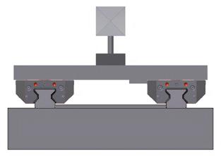
Parallelism
Check compliance with parallelism tolerances using a dial gauge and two coupled carriages.
Use the vertical lateral locating surface on the parallel rail as a reference surface. Special adapter plates are available for checking AMS guideways.
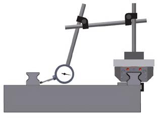
Running Accuracy
Check running accuracy using a laser, autocollimator, or dial gauge. In order to obtain correct results, measurements should always be made at the machine slideway and not at individual carriages.
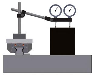
Vertical running measurement with two measurement sensors
Two measurement sensors are recommended in order to identify angle deviations of the carriage along the longitudinal rail axis by differential measurement. Ensure when using a measurement sensor in lateral position that this is as close as possible to the guide rail.
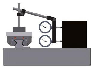
Horizontal running measurement with two measurement probes
Two measurement sensors are recommended in order to identify angle deviations of the carriage along the longitudinal rail axis by differential measurement. Ensure when using a measurement probe in deep position that this is as close as possible to the centre of the guide rail.

CAUTION!
Risk of personal injury posed by sharp edges!
Could result in cutting injuries.
• Wear gloves.
• Protect wipers with an assembly protection strip when passing the carriage over unsealed rail fixing holes.
The following screw covers are available:
• MRK plastic plugs for MR roller guideway
• BRK plastic plugs for BM ball guideway
• MRS brass plugs for MR roller guideway
• BRS brass plugs for BM ball guideway
• MRZ stainless steel plugs for MR roller guideway
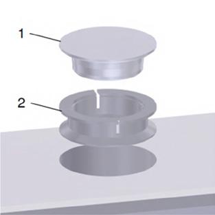
This section describes the installation of MRK plastic plugs for the covering of rail fixing holes in MONORAIL MR and BRK and MONORAIL BM guide rails.
Identification
The marking on the reverse side of the plastic plugs can be used to identify whether they are MRK plastic plugs for MONORAIL MR (right in Fig. 52) or BRK plastic plugs for MONORAIL BM (left in Fig. 52).
For plastic plug dimensions see „Appendix“ on page 72.
Required tool
Carry out the installation using a plastic hammers and a spacer, e.g. a perspex block or assembly rail.
Assembly process
1. Clean the rail fixing hole.
2. Place the plugs into the rail fixing holes. Ensure that the plugs are set parallel with the rail surface.
3. Hammer the plugs in lightly.
4. Check that they are sitting properly.
5. Remove any swarf.
6. Hammer the plugs in until flush.
7.2.2 MRS/BRS brass plugs
CAUTION!
Risk of personal injury posed by sharp-edged rail fixing holes and sheared-off or airborne brass swarf!
Could result in cutting injuries.
• Wear gloves.
• Wear protective goggles when working with compressed air.
Risk of personal injury posed by non-compliance with manufacturer's guidelines!
Hydraulic components can become damaged and malfunction, resulting in injury.
• Follow the manufacturer's instructions for installation, operation, and maintenance.
This section describes the installation of MRS plugs for the covering of rail fixing holes on MONORAIL MR guide rails and BRS brass plugs in MONORAIL BM guide rails using the MWH or BWH hydraulic assembly tool and the MZH hydraulic cylinder.
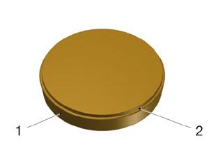
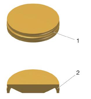
Identification
The MRS and BRS brass plugs generally have a differing construction. The following shows the geometric properties of the different plugs by which the brass plugs can be identified.
MRS brass plugs possess a conical external contour (1). The top surface of the plug (2) has a ring-shaped indentation.
BRS brass plugs have a ring-shaped groove (1). The brass plugs have a recess on their underside (2).
BRS plugs require a special BM rail with non-chamfered mounting holes.
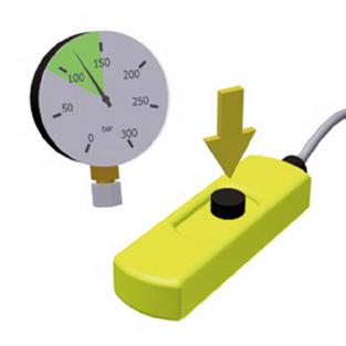
Hydraulic unit
Recommended performance specifications:
• Nominal working pressure 200 to max. 350 bar
• Capacity> 5.8 l/min at 190 bar
MWH/BWH* assembly tool
SCHNEEBERGER recommends the MWH/BWH hydraulic assembly tool for proper installation of brass plugs. This consists of a size-dependent sliding shoe with MWH/BWH pressing stamp together with a universally usable MZH hydraulic cylinder, and must be ordered separately. The cylinder is a simple-to-operate block cylinder with spring return. The required quick coupling is not included in delivery.
Although the MWH/BWH assembly tool is maintenance-free in principle, the pressing stamp may display signs of wear after lengthy use. This can affect the achievable
position tolerance of the plugs and lead to the permissible values being exceeded. The pressing stamp must therefore be checked at regular intervals and replaced if necessary. The stamp can be obtained from SCHNEEBERGER as a replacement part.
In the case of the MZH hydraulic cylinder, the maintenance regulations set out in the manufacturer's operating instructions should be followed.
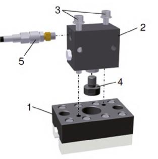
Assembly:
1. Screw the pressing stamp (4) into the hydraulic cylinder (2) by hand until it stops and lightly tighten.
2. Connect the MZH hydraulic cylinder (2) and the gliding shoe (1) with the screws (3) supplied.
3. Connect the hydraulic unit to the 1/4" hydraulic thread of the hydraulic cylinder using the quick coupling (5).
4. For the dimensions of the assembly tool, see Dimensions of accessories on page 71
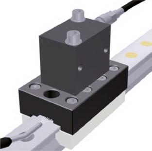
Assembly process
1. Mount the MWH/BWH assembly tool onto the guideway. An MRM/BRM assembly rail is recommended for this purpose.
*Figures show MWH. Differing gliding shoe in case of BWH.
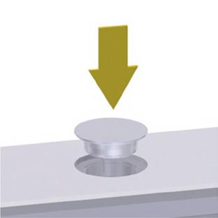
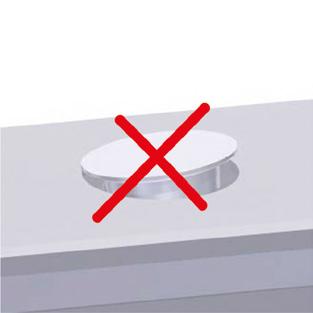
2. Insert MRS brass plugs (conical) with the smaller-diameter side facing down. Insert BRS brass plugs with the recess side facing down.
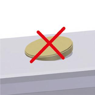
Ensure that the plugs sit parallel to top surface in the fixing holes.
3. Slide the assembly tool over the plugs and position it centrally.
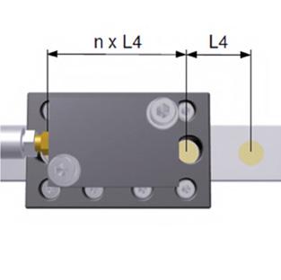
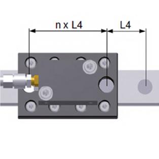
4. Slide the assembly tool until both external control holes or recesses are positioned exactly over a rail fixing hole. (Depending on the size, control holes are one or two L4 hole spacings from the installation position.)
Ș The stamping position has been reached.
NOTE: In order to install the plugs at the extreme end of the rail, the assembly tool can be slid beyond the rail end.
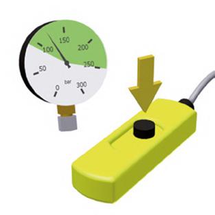
5. Switch on the hydraulic unit and set the desired pressure using the pressure acontrol valve.
Recommended pressure:
• MRS: 80 to 120 bar (250 bar for MR 100)
• BRS: 80 to 120 bar
NOTE: The stamping pressure required is dependent on the size and manufacturing tolerances. Individual cases may require that a higher pressure is used.
Risk of material damage posed by exceeding the permissible operating pressure!
Plugs/tool may be destroyed.
• Under no circumstances exceed the hydraulic cylinder's permissible operating pressure of 350 bar.
6. Briefly operate the one-handed control panel to activate the hydraulic cylinder.
Ș You will hear a clear clicking sound.
7. mmediately release the hydraulic cylinder's power switch.
Ș The hydraulic cylinder will return to its initial position.
8. Slide the assembly tool to one side.
Ș Plug has been pre-pressed with a protrusion of approx. 0.2 - 0.3 mm above the rail surface.
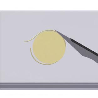
9. Remove any swarf caused by the pressing procedure or clear with a suitable tool (scalpel, sharp knife, etc.).
Ensure that plugs and rails are not scratched.
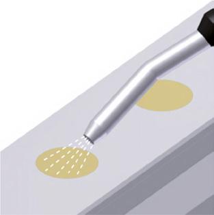
10. Blast loose swarf from the rail surface using compressed air. If necessary, clear remaining swarf using a brass brush. Check that all swarf has been removed.
11. Blast the gap between the gliding shoe and the upper surface of the rail with compressed air to remove any swarf adhering to the pressing stamp.
12. Slide the assembly tool once again over the plug undergoing pressing and position it. Repeat the pressing procedure.
Ș The plug has been fully stamped in and is now flush with the rail surface.
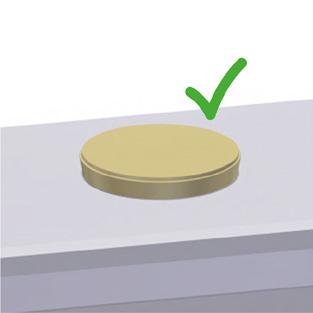
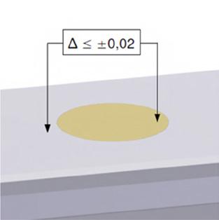
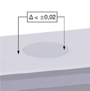
• Check that any height difference between the rail and the upper surface of the plug is permissible (+/- 0.02 mm measured at the edge of the plug or fixing hole).
• If necessary, repeat the pressing procedure with a higher pressure until the correct position has been achieved.
13. Ensure that no residual swarf or burrs are present. If necessary, finish the plug and rail surface with a polishing sponge.
14. Ensure that the plug is positioned correctly.
Once properly installed, the brass plugs are fixed into the guide rail fixing holes very firmly. We therefore recommend that disassembly is carried out using an appropriate extracting device. A standard Allen screw is suitable for this purpose. For recommended screw and core hole diameters, see „Screw tightening torques“ on page 75.
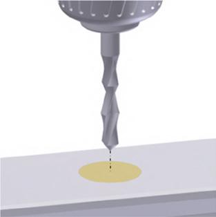
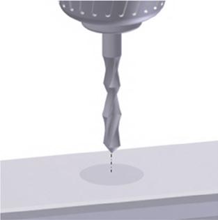
1. Make a punch mark in the centre of the plug and then drill through the plug at this point using a portable drill. Take care not to damage the guide rail fastening screw. The drill diameter should be selected in accordance with the Allen screw used.
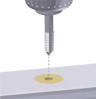
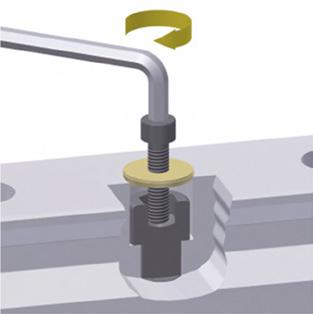
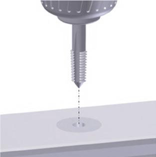
2. Use a thread cutter to cut a thread into the plug. Remove any swarf from the thread.
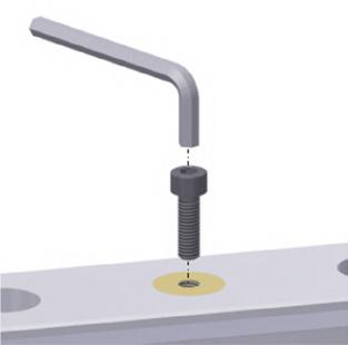
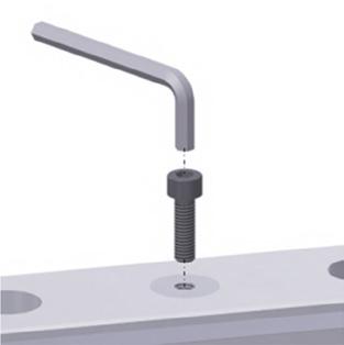
3. Screw the Allen screw into the plug by hand until the tip of the screw comes into contact with the head of the guide rail fastening screw.
4. Tighten the screw using a suitable Allen wrench.
Ș The plug will be forced upwards (see figure).
5. Continue tightening the screw until the plug is fully extracted.
6. Remove the plug by hand.
7. Check the guide rail fixing hole and fastening screw for damage. If necessary, finish the fixing hole with a grinding tool and replace the fastening screw.
7.2.3
CAUTION!
Risk of personal injury posed by sharp edges!
Could result in cutting injuries.
• Wear gloves.
• Protect wipers on carriages with an assembly protection strip when passing the carriage over unsealed rail fixing holes.
CAUTION!
Risk of personal injury posed by non-compliance with manufacturer's guidelines!
Hydraulic components can become damaged and malfunction, resulting in injury.
• Follow the manufacturer's instructions for installation, operation, and maintenance
This section describes the installation of MRZ steel plugs for the covering of rail fixing holes on MONORAIL MR guide rails using the MWH hydraulic assembly tool.
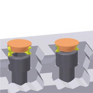
Functional principle
Two-part MRZ steel plugs made from non-rusting stainless steel consist of the actual plug (1) and a clamping ring (2). This has two ring-shaped flanges and an upper surface featuring multiple slots. During assembly, the clamping ring is laid loose onto the screw head in the guide rail fixing hole. The slightly conical plug has a plate-shaped upper surface with a diameter that corresponds approximately to that of the guide rail fixing hole.
Pressing the plug into the clamping ring causes the latter to expand slightly, applying the ring to the wall of the fixing hole and creating a locking force between the fixing hole and the plug. This functional principle ensures a very firm and secure grip and sealing of the guide rail fixing hole, as well as a flush positioning of the plug in relation to the guide rail surface for the optimal functioning of carriage wipers.
Required tool
MWH installation tool
For a description of the MWH assembly tool and its assembly, see „MRS/BRS brass plugs“ on page 34.
Assembly process
1. Slide the MWH assembly tool onto the guide rail. Recommendation: Use an MRM assembly rail for this purpose.
2. Lay the clamping ring inside the guide rail fixing hole with the slitted surface facing upward.
3. Lay the plug onto the ring with the conical side facing downward.
Ensure that the plugs sit plane-parallel to the rail surface in the fixing holes.
NOTE: The clamping ring has a small recess on the inside of its upper portion that enables the plug to align with it under light pressure.
Fig.76
4. Slide the assembly tool over the plug and position it centrally.
5. Slide the assembly tool until both external control holes or recesses in the tool (MWH 25 - 100) are positioned exactly over a guide rail fixing hole. (Depending on the size, the control holes are one or two L4 hole spacings from the installation position.)
Ș The stamping position has been reached.
NOTE: In order to install the plugs at the extreme end of the rail, the assembly tool can be slid beyond the rail end.
6. Switch on the hydraulic unit and set the desired pressure using the pressure control valve.
Recommended pressure:
100 to 200 bar
NOTE: The stamping pressure required is dependent on the size and manufacturing tolerances. Individual cases may require that a higher pressure up to approx. 250 bar is used.
Risk of material damage posed by exceeding the permissible operating pressure!
Plugs/tool may be destroyed.
• Under no circumstances exceed the hydraulic cylinder's permissible operating pressure of 350 bar.
7. Briefly operate the one-handed control panel to activate the MZH hydraulic cylinder.
Ș You will hear a clear clicking sound.
8. Immediately release the hydraulic cylinder's power switch.
Ș The hydraulic cylinder will return to its initial position.
9. Slide the assembly tool to one side.
Ș The plug has been fully pressed in and is now flush with the guide rail surface.
10. Ensure that the plug is positioned correctly:
• Check that any height difference between the rail and the upper surface of the plug is permissible (+/- 0.02 mm measured at the edge of the plug or fixing hole).
• If necessary, repeat the pressing procedure with a higher pressure until the correct position has been achieved.
Risk of material damage posed by use of incorrect screws!
Cross wipers/carriages may become damaged.
• Safe functionality of the steel plugs is only guaranteed with the use of DIN 912/ISO 4762 high-headed screws to fasten the guide rails.
• Any markings on the screw-head must not be raised.
Once properly installed, the steel plugs are fixed into the guide rail fixing holes very firmly. We therefore recommend that disassembly is carried out using an appropriate extracting device. A standard Allen screw is suitable for this purpose. For recommended screw and core hole diameters, see Table „Dimensions of MRZ steel plugs“ on page 72.
1. Make a punch mark in the centre of the plug and then drill through the plug at this point using a portable drill. Take care not to damage the guide rail fastening screw. The drill diameter should be selected in accordance with the Allen screw used.
2. Use a thread cutter to cut a thread into the plug. Remove any swarf from the thread.
3. Screw the Allen screw into the plug by hand until the tip of the screw comes into contact with the head of the guide rail fastening screw.
Fig.82
4. Tighten the screw using a suitable Allen wrench.
Ș The plug together with the clamping ring will be forced upwards (see figure).
5. Continue tightening the screw until the plug is fully extracted.
6. Remove the plug by hand.
7. Check the guide rail fixing hole and fastening screw for damage. If necessary, finish the fixing hole with a grinding tool and replace the fastening screw.
This section describes the installation of the MAC/BAC cover strip for MONORAIL MR and BAC cover strip for MONORAIL BM to cover the mounting holes, using the MWC assembly tool for MR and the BWC assembly tool for BM.
Risk of personal injury posed by cover strip edges and ends! Could result in cutting injuries.
• Wear gloves.
Risk of material damage posed by bent cover strips!
Cover strips can become bent during storage and transportation, which may cause damage to carriage wipers.
• Always ensure that cover strips are supported along their full length.
• Do not use bent cover strips.
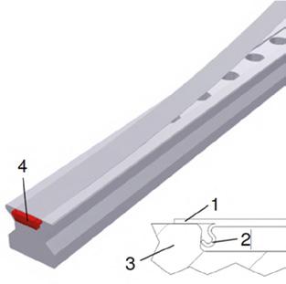
The MAC cover band made from stainless spring steel consists of a smooth steel strip (1) with S-shaped spring elements on the underside (2) for fastening. Installation is carried out on special cover strip rails (3) with a dovetail groove. Once installed, the cover strip lies flat with a slight curvature on top of the guide rail covering its upper surface in the area where the guide rail fixing holes are located. The edges of the guide rail upper surface are left uncovered. The strip is held in place by the S-shaped spring elements, which hook into the guide rail groove and guarantee a firm and secure grip thanks to the resulting locking fit. The strip is also secured at its ends by special end pieces (4) which prevent the retaining elements from springing back and the cover strip from lifting. The end pieces simultaneously seal the frontal gap between the guide rail and cover strip.
Required tool
MWC/BWC assembly tool
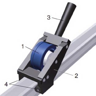
1 Pressure roller
2 Housing
3 Handle for manual operation
4 Sliders for passing the workpiece along the guide rail
The MWC/BWC assembly tool is maintenance-free. Check the assembly tool regularly and replace it if necessary, as extended use may lead to signs of wear on the sliding components.
The manual MWC assembly tool is recommended by SCHNEEBERGER for proper installation of MAC cover strips and can be obtained from SCHNEEBERGER separately.
Installation procedure for one-piece strips
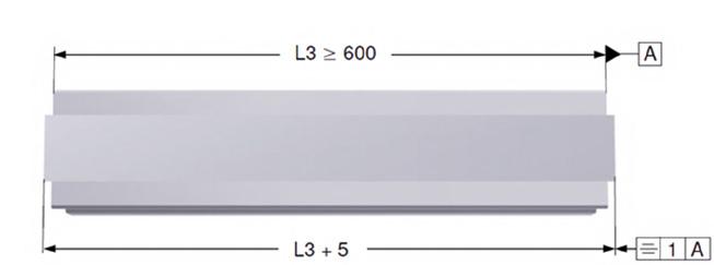
Minimum length
• Minimum length for guide rails with cover strip without fixing bracket: L3 ≥ 600 mm
• Where guide rail length < 600 mm, fixing brackets must be used to secure strip ends against lengthwise slippage (see „Completing installation of one-part and multi-part strips“ on page 47).
1. Lay the cover strip loose on the guide rail.
2. Adjust the cover strip so that it is positioned centrally.
• Where the standard end pieces are included for securing the strip, the strip will be slightly longer than the guide rail.
• A correctly-aligned strip should have 2 – 3.5 mm of overhang at each rail end.
NOTE: Ensure that this value is observed for proper functioning of the end pieces.
Installation
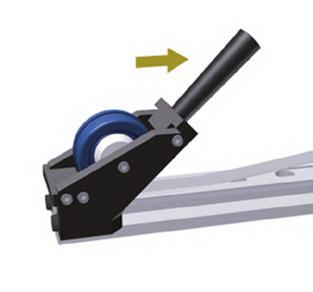
1. Mount the MWC/BWC assembly tool onto one end of the guide rail.
Ș Handle will point towards guide rail end.
2. Press the strip into the guide rail groove:
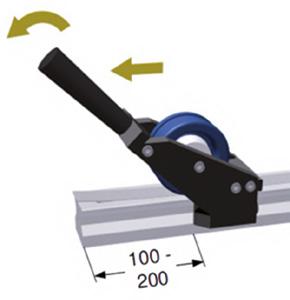
a) Begin approximately 100 - 200 mm from the guide rail end b) Simultaneously tilt the tool and move it forwards.
Ș The strip will snap audibly into the groove.
NOTE: Do not bend the free strip end at the end of the guide rail. Only move the assembly tool up to the end of the guide rail. Do not move the pressure roller over the end of the guide rail whilst applying pressure.
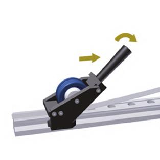
3. Turn the handle of the assembly tool in the direction of installation.
4. Slide the assembly tool back over the guide rail.
5. Press the strip into the groove along the full length of the guide rail. Move the tool lengthwise whilst tilting it forwards.
Installation procedure for strips > 6000 mm
Delivery condition: Cover strips with a length > 6000 mm are delivered oversized and must be cut off on one side by the customer after installation.
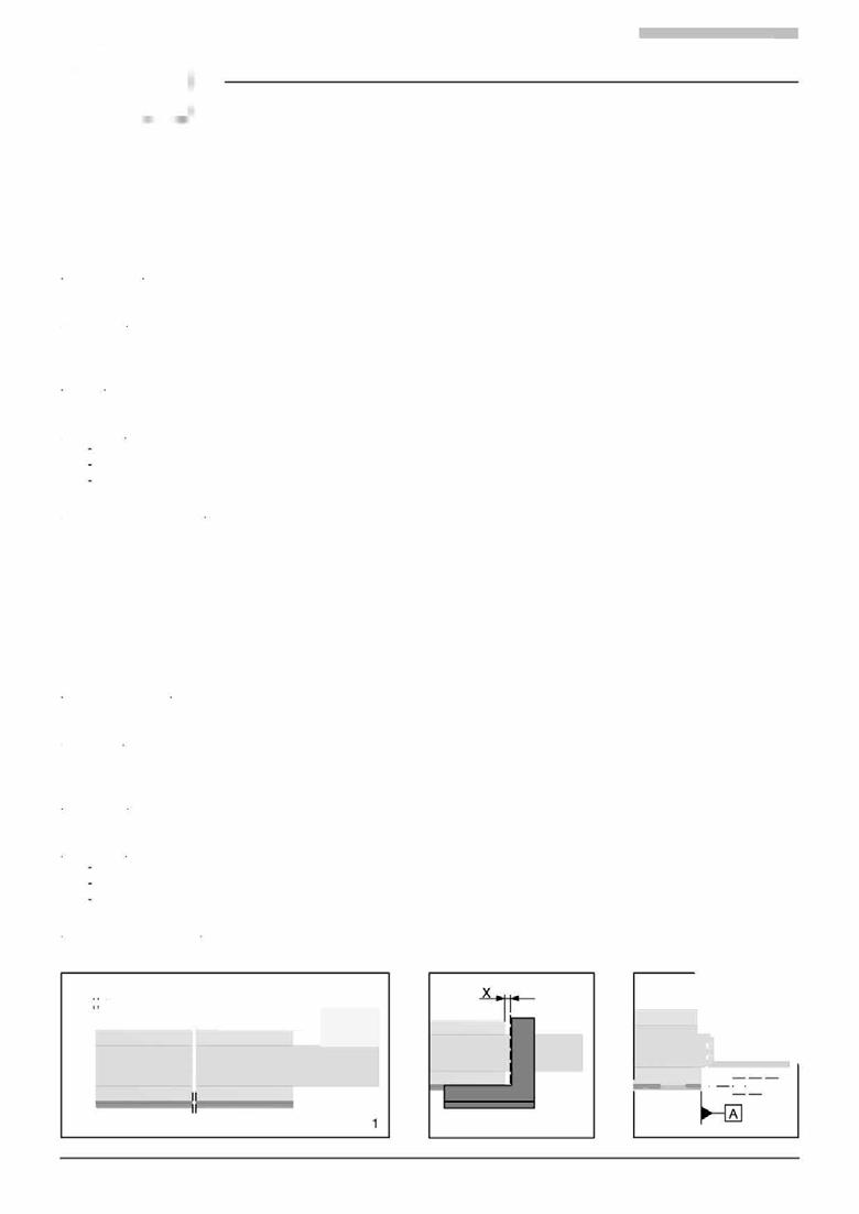
Alignment: Before installation, place the cover strip loose on the rail and align so that the strip protrudes X 2 - 3.5 mm at one end of the rail. This value must be observed to ensure safe functioning of the end pieces for securing the strip. The strip will protrude approx. 100 mm beyond the end of the rail (Fig. 1) on the opposite side.
Installation: Fit the cover strip over the entire rail length, starting at the rail end with the short overhang, in accordance with the 7.4.2 Cover strip MAC/BAC installation instructions
Cutting off: After installation, cut oft the long strip end:
- Mark the cutting edge with the aid of an angle (Fig. 2) (overhang X = 2.5 ± 0.5 mm).
- Cut off the cover strip square with a parting-off grinder or hacksaw (Fig. 3).
- Deburr top and bottom of cut edge, e.g. with an oilstone.
Completing installation: Check that cover strip is correctly located and fit end pieces on both sides in accordance with MAC/BAC installation instructions.

Installation procedure for multi-part strips
General
Multi-part strips should only be used if e.g. multi-part guide rails have been laid due to a long axis length and the installation situation requires it. A butt joint always represents a potential problem spot for carriage wipers and should be avoided.
Minimum length
Minimum section length: 600 mm
Guide rail installation
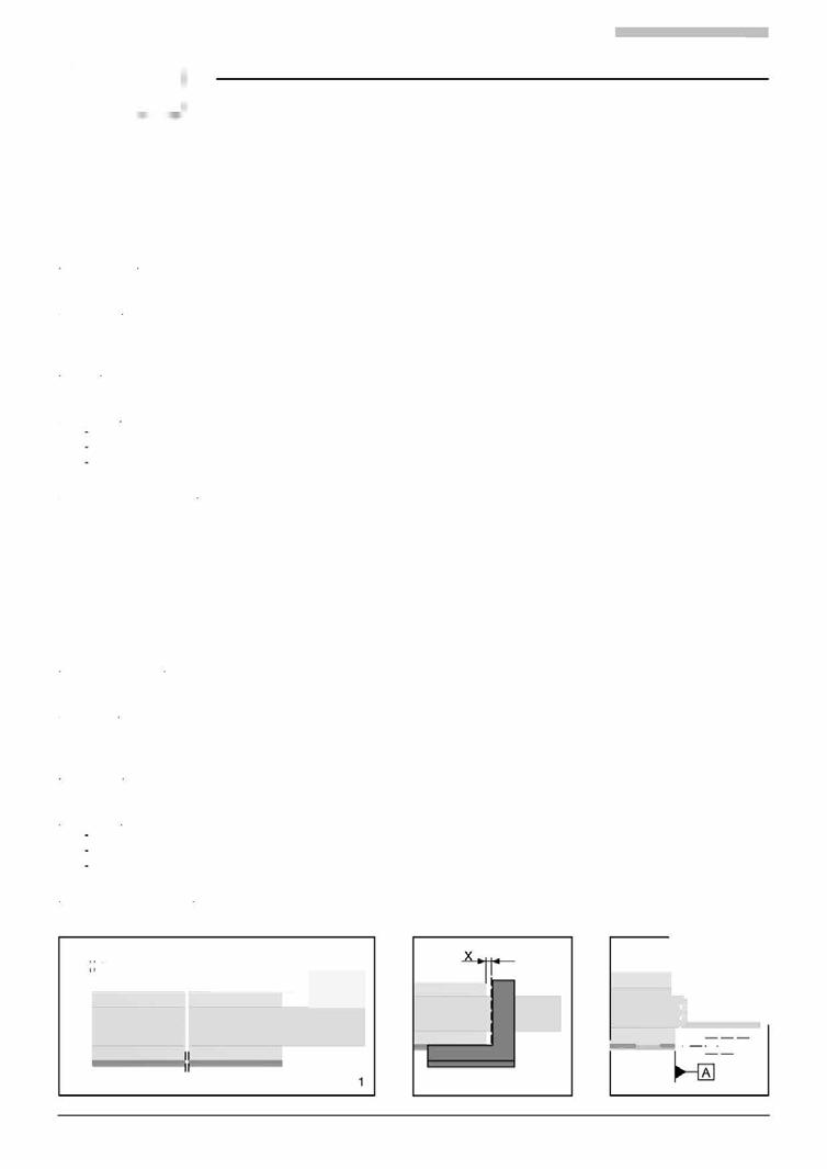
Install multi-part guide rails for cover strips in accordance with „Handling guide rails“ on page 21. Install the rail segments so that at each butt joint the groove for the cover strip is continued by the subsequent rail section (see figure).

Multi-part strips should be installed according to the same process used in the case of one-part strips (see „Installation procedure for one-piece strips“ on page 45). Follow the numbering of the strips. As with multi-part guide rails, the individual strip components are provided with a butt joint number on their underside in the joint area.
In the future, the cover tapes MAC and BAC will be additionally labeled on the protective foil:
• SCHNEEBERGER + type + size
• Arrows for orientation
The arrows must point to the R1 side during both cutting and mounting (regardless of the stop side of the guide rails).
1. Install the first strip section.
2. Install all further strips so that they are seamless at each joint (gap size < 0.2 mm).
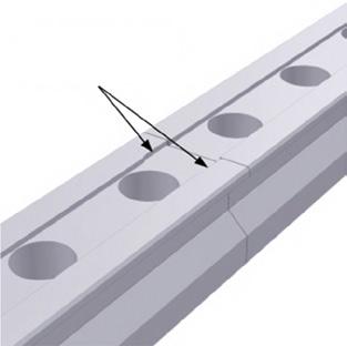
Cover strips and guide rails are not the same length in the case of multi-part guide rails. Always install strip and guide rail joints offset by approx. 70 mm.
Completing installation of one-part and multi-part strips
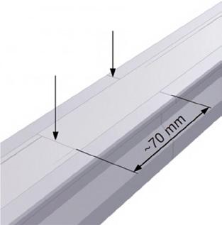
1. Check that the strips have been positioned correctly and consistently and are flush with the guide rail/s:
• The cover strip has a slight upward curvature, with its edges touching the guide rail surface.
• The permissible gap size between guide rail and cover strip is 0.04 mm.
• Strip height including curvature is max. 0.6 mm.
• Height difference between cover strips at butt joints is max. 0.03 mm.
1. Slide end pieces into the gap between cover strip and guide rail groove at each end of the guide rail until they stop.
2. Lightly moisten the full guideway surface with the MONORAIL guideway lubricant.
NOTE: In the case of cover strips with a length < 600 mm, secure the strip ends with a steel bracket instead of the end pieces (see next section "Steel securing bands").
Steel securing bands
In cases of increased mechanical stress, e.g. in an open swarf area, the strip ends can be secured with a steel bracket in place of the red plastic end pieces. In this case, the protruding strip ends must be severed straight and burr-free and a threaded fixing hole introduced into the frontal end of the guide rail. Retrofitting of steel securing bands is only recommended if the guide rails have been inductively hardened. For dimensions of the securing bands and the threaded fixing hole, see „Appendix“ on page 72.
Steel securing bands are not part of the standard cover strip delivery package and must be ordered separately.
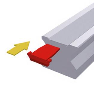
1. Removing the end pieces:
a) Hook an Allen wrench into the underside of the end piece.
b) Pull the end piece out of the groove, pulling parallel to the guide rail.

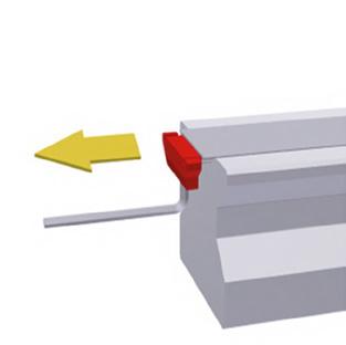
2. Use a screwdriver to lift the cover strip a few millimetres out of the groove at one end of the guide rail.
3. Take hold of the strip end by hand and lift it.
4. Insert the screwdriver laterally between the guide rail and the cover strip.
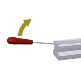
5. Slide the screwdriver along the length of the guide rail, lifting the cover strip. Take care not to bend or twist the strip. Do not allow the cover strip or guide rail to become scratched.
Ș The cover strip is freed from the groove.
6. Uninstall the cover strip from the full length of the guide rail.
7. Check the cover strip for damage:
a) Straighten cover strips that are slightly bent.
b) Replace cover strips that are strongly bent, twisted, scratched, or otherwise damaged.
8. Always replace end pieces. End pieces can become damaged during disassembly or lose their retaining force.
7.3 Removing the protective installation film for additional wipers (optional) Carriages with ZBV/ZCV additional wipers are delivered with an installation protection film if the rails are screw-fastened from above and the fixing holes covered with plugs. The installation protection film protects the sealing lips during installation and should only be removed once the guide rail fixing holes have been sealed.
Risk of material damage posed by sliding carriages over the edges of open guide rail fixing holes! Additional wipers can become damaged.
• Only remove protective installation film once fixing holes have been sealed.
Pull the protective installation film away from the carriage in the direction of the guideway.
Lubrication connections
General
• lube connections are plastic threads. Exercise caution when inserting lube connection pieces.
• Maximum tightening torque = 0.5 Nm.
• Recommended screw-in depth into front plate 4 mm.
• Lube connection pieces with conical thread: max. screw-in depth accords with thread length.
Lubricant distribution:
Carriages are available with standard lubricant distribution and with separated lubricant distribution.
In the case of standard lubricant distribution, all four running surfaces are supplied with a single lube connection. The lubricant is distributed to all tracks in the front plate and redirection units.
In the case of separated lubricant distribution two lube connections supply the right and left tracks separately.
MONORAIL MR includes a pin indicator which indicates whether a front plate is built for standard or separated lubricant distribution.
• Black pin - standard lubricant distribution.
• Grey pin - separated lubricant distribution.
In order to convert MONORAIL MR carriages from standard to separated lubricant distribution, the front plate must be fully replaced.
Installing the lube connection pieces
1. Ensure that the lube connection in the front plate is open.
2. Screw the lube connection pieces into the carriages
• When lubricating from above, place the sealing ring included into the depression in the front plate and if necessary strengthen its grip by applying some lubricating oil.
• If a centralised lubricating system is available, connect the carriage to the centralised lubricating system.
Initial lubrication (carried out by customer)
The initial lubrication supplies the rolling elements with lubricant. It also provides the wipers of the carriage with protection and a corrosion protection. A thin film of lubricant on the guide rails reduces lubricant consumption at the start of operation, as any surface roughness on the guide rail will be pre-filled with lubricant.
For lubricant quantities, see „Amount of lubricants“ on page 77.
Apply the initial lubrication to the carriages in accordance with the following procedure:
1. Lightly moisten the guide rails with the guideway lubricant.
2. Slide the carriages more than three times their length several times.
3. Insert the required quantity of lubricant into the carriages.
Risk of material damage posed by improper handling of contact elements!
The oil-delivering contact elements are slightly pre-stressed and can be destroyed by improper handling.
• Carefully slide the lubrication plate over the end of the guideway.
• Only install lubrication plates when the carriage is on the guideway.
Lubrication plates are delivered ready for installation, i.e. filled with oil.
• When using lubrication plates on the carriages, carry out an additional filling with grease. For recommended lubricant quantities, see „Amount of lubricants“ on page 51.
• Only use lubrication plates in pairs.
• Do not use lubrication plates if the guideways are in direct contact with coolant.
• Use covers to protect guideways from dirt, swarf, and coolants, using additional wipers if necessary.
• Apply regular lubricating strokes over the full travelling distance of the axis.
• Include the lubrication plates in the machine maintenance plan:
• Check the wipers regularly for wear.
• Check the oil film on the guide rail track.
• Carry out lubricating strokes.
• Refill the SPL.
1. Loosen and remove the upper screws on the standard front plate (In the case of MONORAIL MR the lower screws remain screwed into the carriage, whereas in the case of MONORAIL BM the front plate must be held).
2. In the event that the central lube hole in the front plate is closed with a plastic protective plug, remove this and replace it with a set screw.
3. Carefully slide the lubrication plate over the guide rail end to the carriage.
4. Secure the lubrication plate using the long screws included in the SPL delivery.
1. Loosen and remove the screws from the lubrication plate. In case of BM, takie care to hold the front plate in place as rolling elements may otherwise be lost.
2. Remove the lubrication plate from the guideway end.
3. Carefully slide the new lubrication plate over the guideway end to the carriage.
4. Fasten the new lubrication plate.
Installing ZCV/ZBV additional wipers or ASM/ABM metal wipers
1. Remove the screw plug from the front central lube hole. For installation of the additional wiper, see „ZCV/ZBV additional wipers“ on page 66. For installation of the metal wiper, see „Replacing ASM/ABM metal wipers“ on page 67.
2. Install the additional wiper and/or metal wiper onto the lubrication plate using the screws included.
3. Re-seal the front central lube hole with the removed screw plug or using a lube nipple.

Refilling
The lubrication plate can be refilled via the front, middle, or lateral lube holes (size MR 25 only from the front). For ordering information and dimensions, see the Technical data section of the MONORAIL catalogue. To do this, remove the applicable screw plug using an Allen wrench and replace it with a lube nipple. A conical lube nipple is available for order as an accessory.
Refilling is carried out for example using an oil press via a conical or flush type lube nipple screwed into one of the prepared lube holes in the front, the middle, or laterally. A special oil bottle offered by SCHNEEBERGER as an accessory can also be used. Refilling is carried out in this case directly into the SPL lube hole, eliminating the need for a lube nipple.
Lubrication plates are refilled using the oil quantities in the table (see „Amount of lubricants“ on page 77) in approximately 4 to 5 stages, depending on the size and condition of the lube connection used.
In order to achieve optimal refilling results, it is recommended that both lateral lube connections are used.
An interval of approx. 5 minutes should be left between each individual filling stage. Oil release should be checked at the felt contact points with the guideway. The filling quantity generally depends on the drainage rate of the lubrication plates.
Refilling SPL-MR
See „Lubricating volumes for SPL refilling“ on page 78.
Refilling SPL-BM
See „Lubricating volumes for SPL refilling“ on page 78.
The lubrication plates should be refilled in accordance with the applicable operating conditions. As a guideline, the following refilling intervals can be assumed:
• BM 15 - BM/MR 35: 2,500 km
• MR/BM 45 - MR 65: 5,000 km
An accurate determination of the intervals can only be achieved under actual operating conditions. More frequent refilling will be required under unfavourable conditions, or in an unfavourable climate or working environment. Irrespective of the distance travelled, refilling is necessary after a maximum of 12 months operation.
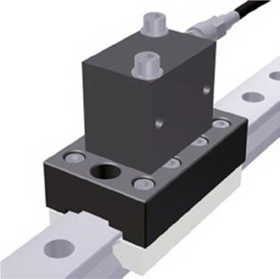
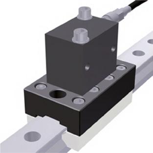
7.5 Laying the electronics housing and cables
housing
The sensor unit of the measuring system (excluding AMSA 3L) has a separate electronics housing. The electronics housing is mounted near the read head at the machine slide and has an LED display on its front for indicating various operating states.
The electronics housing should be installed in accordance with the following points:
• Fit the electronics housing so that the front of the housing and the diagnostic LED (in the case of AMSD 3B/4B, AMSABS 3B) are easily accessible for servicing.
• Do not lay cables from and to the housing under tension.
• Do not fall below the minimum bending radii (see „Cable bending radi“ on page 78).
Shielded cables are used as KAO extension and connecting cables between the measuring system and controller.
When laying cables for the measuring system, the following points must be observed:
NOTE: Do not lay cables next to interference sources, e.g. magnetic fields from voltage supplies, mains electricity lines, motors, valves, relays and their feeds.
• For cable conduits, ensure that the dimensions of the mounting base comply with the catalogue or connector diameter.
• Ensure an adequate distance from cables carrying interference sources: 0.1 m.
• Employ a grounded separation screen if metal cable ducts are used.
• Ensure a minimum distance of 0.2 m from storage chokes in switched mode power supplies.
• Separate hydraulic hoses and electrical cables.
• Lay the read head cable (4) as statically as possible, e.g. not in a cable carrier (6).
• Use an extension cable (5) as a cable carrier (6).
• Do not use sharp-edged ducts.
• Lay cables without any tensile load.
• Do not fall below the minimum bending radii (see „Cable bending radi“ on page 78).

The cable carrier (6) is not included in the scope of delivery.
Connecting the measuring system and suitable extension cable length
MONORAIL AMS is connected directly to the drive controller of the axis. Extension cables with a length of up to 50 m can be used depending on the model of sensor unit and controller used.
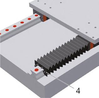
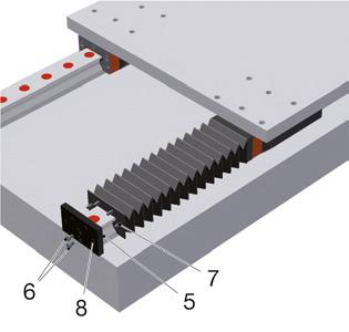
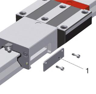
7.6 Installing a FBM/FBB bellows - optional
Bellows are mainly used as an additional form of protection for carriages against dust and splashes of water.
1. Prior to installing the bellows, ensure that guide rail fixing holes are sealed with plugs and the cover strip.
2. Slide the machine slide into approximately the centre of the stroke.
3. Insert the adapter plate (2) in front of the first carriage (1). Ensure that the countersink into the fixing hole is on the side facing away from the carriage.
4. Secure the adapter plate to the middle lube connection thread of the front plate using the central screw (3) (max. tightening torque 0.5 Nm).
5. Mount the pre-assembled bellows (with supporting frame and rivets) onto the guideway.
6. Snap the rivets (4.7) at the end of the bellows into the corresponding holes in the adapter plate.
7. Insert the end plate (5) at the end of the guideway. Ensure that the side with the countersink into the fixing holes is on the side facing away from the carriage.
8. Secure the end plate using the screws included (6).
9. Snap the rivets (4,7) at the end of the bellows into the corresponding holes (8) in the adapter plate.
10. Check that the bellows slide well on the guideway and that the folds are not too strongly compressed or stretched in the slide end positions.
Following installation, check that the guideway and accessories have been installed are functioning correctly:
Move the machine slide by hand over the full stroke, ensuring that push force remains constant and that the movement is jerk-free.
Ensure that the lubricant lines are properly connected and vented, and that the carriages are sufficiently supplied with lubricant.
In order to test lubricant circulation, activate the lubricant supply whilst simultaneously moving the carriage on the guideway. A thin film of lubricant will appear on the guideway.
Ensure that no lubricant is leaking from the lubricant lines, the lube connection parts, or from between the front plate and carriage body.
Cover strip and plugs
NOTE: Burrs and protruding parts of sealing elements can damage the wiper lips of the carriages during operation.
Ensure that cover strips and plugs are positioned consistently and flush with the guideway.
• Cover strips must lie cleanly and without gaps on the guide rail surfaces and must not be bent. The ends must be secured with a bracket or end pieces.
• Plugs must be fitted flush and parallel with the guide rail surface; they must not protrude or sit too deeply. Ensure in the case of plastic and brass plugs that all residual swarf or burrs have been removed.
Front plates and additional wipers
Check that carriage front plates and accessory parts as well as additional wipers are positioned and functioning correctly.
Check that lubricant applied to the guide rails has been wiped off cleanly. Ensure that lubricant on guide rail surfaces that has been passed over does not form any streaks.
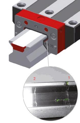
Checking wipers
1. Clean lubricant and dirt particles from guide rails and wiper sealing lips.
2. Apply (ideally coloured) lubricating grease or oil to the tracks of the guideway and distribute evenly with a cloth.
3. Move the carriage with wipers a few centimetres over the moistened guideway.
Ș Effect of wipers is clearly recognisable (1), excess lubricant is wiped ahead.
4. Move the carriage back to its starting position.
Ș The lubricant on the sealing lip is drawn backwards.
5. Move the carriage forward again (not as far as moved in the first stroke).
Ș A thin, continuous line of lubricant is visible on the guideway track (2).
NOTE: An absent or interrupted line of lubricant is indicative of an improperly-fitting wiper.
The wiper must be exchanged if this is the case.
The wipers must form an even gap around the guide rail profile and should not make contact with the guide rail at any point. Use special metal wipers for AMS systems. Check that the wipers are correctly positioned using a feeler gauge and by moving the machine slide.
Check that the bellows are correctly fitted to the adapter plate and end plate. Ensure that the bellows are able to move freely.
Traverse the machine axis, checking that the bellows slide well along the guideway. Check that the folds are not too strongly compressed or stretched in the slide end positions. 7 Completing
Prior to commissioning, check the functionality of the guideway:
• For proper installation of the guideway, see "6 Installation" on page 18
• For system accuracy and push force see "„Completing installation“ on page 32 , and 7.7 Checking the results of the installation on page 55.
• For supply of lubricant, see „Checking the results of the installation“ on page 57
• For removal of the corrosion protection and oiling the guideway, see „Corrosion protection“ on page 17 and „Handling guide rails“ on page 21.
• For initial lubrication, see „Lubrication“ on page 51 and „Checking the results of the installation“ on page 57.
• For installation and positioning of guideway cover strips, see „Installing the screw cover“ on page 33 and „Checking the results of the installation“ on page 57.
• For wiper functionality, see „Checking the results of the installation“ on page 57
• For positioning and functionality of bellows, see „Installing a FBM/FBB bellows - optional“ on page 56 and „Checking the results of the installation“ on page 57.
Check the functionality of the measuring system:
• Mount carriage with housing onto the guideway so that the recess for the read head is located on the side of the guideway with the measuring scale. The scale side can be identified by the reference mark.
• For battery activation in the case of AMSABS, see „Preparing the measuring system for installation“ on page 18.
• For correct installation of the read head in the housing, see „Installing and connecting the read head“ on page 25.
• For proper laying of cables and electronics box, see „Laying the electronics housing and cables“ on page 54.
• For connection with the controller, see „Laying the electronics housing and cables“ on page 54.
• LED for the operating state display (lights up green after switching on the controller).
• Check the parametrisation of the controller with respect to the measuring system.
9.1 Optical inspection check list
During guideway maintenance, ensure by optical inspection that none of the following are damaged and that no preventable damage to them is impending:
• Check the guide rail surfaces for damage.
• Check the wiper (see „Checking the results of the installation“ on page 57).
• Check cross wiper for damage/wear.
• Check additional wiper (if present) for damage/wear.
• Check the greasing state of the carriage (lubricant discharge).
• Remove the carriage and check it for particles of dirt (see „Handling carriages“ on page 20).
• Remove carriage and check plastic parts for damage (see „Handling carriages“ on page 20).
• Remove residual swarf from the vicinity of the guideway.
9.2 Clean
Risk of material damage posed by improper cleaning!
May result in damage to plastics and guide rails.
• All parts should only be cleaned using rubbing alcohol or white spirit. Do not use any cleaning agents or solvents capable of damaging plastics.
• Clean dirty guideways with a soft, lint-free cloth. Do not use compressed air.
• Avoid direct contact between tools and the guideway's magnetic measuring scale.
9.3 Replacing defective components
Risk of material damage posed by bending sensor slide springs!
When transferring carriages with housing for the AMS measuring system with built-in read head to/from guideway, sensor slide springs can become bent.
• Dismount the read head before transferring carriage to/from guideway.
Risk of material damage posed by scratching the measuring scale!
Swarf caught beneath metal wipers can scratch the magnetic measuring scale.
• Only use metal wipers designated for the AMS measuring system on guideways with magnetic measuring scale.
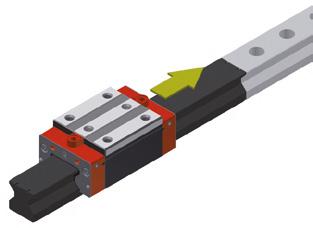
• The carriage and guide rail form a single unit. In the case of matched designs, ensure that the carriages of different guide rails are not interchanged.
• To prevent rolling elements from being dislodged from carriages, use an MRM/ MBM assembly rail when transferring carriages to and from guide rail. The MRM/MBM assembly rail is not included in the standard delivery.
• Should one carriage become damaged, replace all carriages. Should it be unknown which accuracy levels are installed, a G0 system can be installed. This ensures that the original accuracy levels are achieved.
Carriage replacement procedure
Identifying the carriage for ordering spare parts:
Ș The relevant carriage can be identified by its label, see 3.3 Labelling of guide rails and carriages on page 9.
Spare parts:
• STP front plate
• QAS cross wiper for MONORAIL MR/BM
• FRB front panel for MONORAIL MR
• ZCV additional wiper for MONORAIL MR and ZBV for MONORAIL BM
• ASM metal wiper for MONORAIL MR and ABM for MONORAIL BM
• SPL lubrication plate
• Screws
Guide rail replacement procedure:
• Identifying the guide rail for ordering spare parts:
Ș The relevant guide rail can be identified by its label, see 3.3 Labelling of guide rails and carriages on page 9.
Spare parts:
• Screw covers
• Screws
1. Transfer carriages onto MRM/MBM assembly rails.
2. Leave carriages on assembly rails during transportation or storage. Ensure that carriages and associated guide rails are not interchanged.
3. Individually transfer carriages back onto their associated guide rail from assembly rails.
CAUTION!
Risk of crushing posed by moving axis slides!
May result in personal injury.
• Prior to replacing the read head, turn off the main switch and ensure that it cannot be turned back on. Secure the axis if necessary.
Risk of material damage posed by short-circuit currents!
The electronics in the read head are vulnerable to destruction by short-circuit currents.
• Prior to replacing the read head, disconnect the power supply and ensure that it cannot be restored without authorisation.
Fig.112
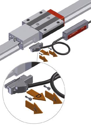
1. Turn off the main switch and ensure that it cannot be turned back on.
2. Dismount protective covers if required.
3. Ensure the proper positioning of the out-of-service axis.
4. Unplug the read head connecting cable.
5. Loosen the fastening screws of the separate electronics housing.
6. Loosen the fastening screws fixing the read head to the housing.
a) Remove the cover plate (only in the case of AMSABS 3B, 4B).
b) Slide the read head laterally in its mounting groove until it is radially freely mobile (only in the case of AMSABS 3B, 4B).
7. Carefully remove the read head from the housing at a right angle to the installation surface.
8. Make a record of the fault and serial number and package the read head.
1. Check the read head installation surface on the housing for contaminants.
2. Clean the magnetic measuring scale.
3. Carefully unpack the new read head.
4. Clean the sensor slider of the read head if required.
5. In the case of AMSABS, activate the battery (see „Battery AMSABS / AMSABS 3L“ on page 63).
6. Carefully insert the read head into the recess in the housing at a right angle to the installation surface, ensuring that it is positioned flat.
7. In the case of AMSABS 3B and 4B, slide the read head parallel to the guide rail until it reaches its screwing-in point:
• The measuring system will automatically identify its absolute position during installation.
• The measuring system is ready to operate immediately following installation.
• Once the controller is switched on, the LED will light up green.
8. Tighten the fastening screws at the housing (tightening torque 1.1 Nm).
9. Lay the cable and secure the separate electronics housing. For this, follow the guidelines in section „Laying the electronics housing and cables“ on page 54.
10. Plug in the connecting cable plug and tighten the union nut by hand.
11. Switch the power supply back on.
12. In the case of AMS with operating state display, ensure that the LED lights up green.
13. Check the machine zero point and recalibrate if required: Execute a reference move on the drive controller.
Risk of material damage posed by collision!
Failure to inspect and adjust (where necessary) the machine zero point can result in the collision of machine components with other components.
• Calibrate the zero point following every read head installation.
NOTE: Positional recognition of equidistant reference marks can vary by ± 0.5 mm between different read heads.
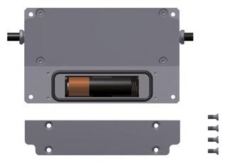
9.5 Battery AMSABS / AMSABS 3L
Battery used: Lithium Type AA- LS 14500- 3.6V-2400 mAh- SAFT
Battery state display
In the case of the AMSABS, a weak battery state is indicated by the operating condition LED and where necessary on the machine controller.
The electronics housing of the sensor unit contains an accumulator and a buffer battery that ensure system functionality even if the machine is switched off. Short periods of up to 4 weeks are covered by the accumulator without affecting the battery's functional life. This means that in the case of typical usage where the machine is regularly in operation, the buffer battery guarantees functionality of the sensor unit for many years. SCHNEEBERGER recommends in this case that the battery is replaced proactively every 5 years.
In the event that the external power system is switched off for an extended period, the position measurement of the system is retained for approx 1.5 years, although regular movement of the read head shortens this period. If the machine or measuring system is shut down, it is recommended that the activation strip and its underlying magnet are inserted back into the electronics housing (see 7.5 Preparing the measuring system for installation on page 17). This will disconnect the power supply to the sensor unit and prevent the battery from being drained. It will however be necessary to reset the absolute position upon reactivation (see 7.5 Preparing the measuring system for installation on page 17).
1. Unscrew the battery compartment at the rear of the electronics housing.
2. Remove the old battery.
3. Insert the new battery, ensuring that it is the right way around.
4. Check that the O-ring is correctly located in the groove and ensure that O-ring, groove and supporting surface for the lid are clean.
5. Replace the lid on the battery compartment and fasten with screws (tightening torque 0.3 Nm).
6. Dispose of old battery properly in accordance with nationally applicable regulations.
Only use batteries that are not older than one year. Before replacing, check the date of manufacture, which is marked on the battery.
Country China
UK France
Description Year/Month/Day Year/Day Year/Day/ traceability code
Example 16 02 23A 16 054 16 054 A023
Meaning Cell finished the 23rd February of year 2016. A or blank is internal control code
Cell finished the 54lhday of year 2016 (Feb 23)
Cell finished the 54lhday of year 2016 (Feb 23). Batch internal code A023
9.6 Checking and replacing accessories and wear parts
9.6.1 Front plates and additional wipers
Making sure that the carriage seals function properly is a prerequisite in ensuring that the guideway provides a long service life. In general, the seals are designed to be maintenance-free if given sufficient lubrication and kept a clean environment. Certain operating conditions, such as dust or swarf on the guideway or inadequate guideway lubrication, lead to increased wear of the sealing lips.
The wipers on the front plates and additional wipers should be checked for wear at regular intervals (at least every 6 months) and replaced where required.
Replacing cross wipers and additional wipers
Risk to life posed by falling machine elements!
In the case of MONORAIL BM, the front plate is part of the rolling element recirculating unit. Extraction of the front plate will lead to ball loss and can result in falling machine elements. Possible consequences include death and serious injury.
• Under no circumstances should the front plate of the carriage be removed in the case of MONORAIL BM.
When replacing cross wipers and additional wipers, remove the fastening screws from the front plate.
The following should be observed when doing so:
• In the case of MONORAIL BM, under no circumstances should the front plate be removed from the carriage body.
• In the case of MONORAIL MR, the front plate does not need to be removed in order to replace the cross wiper.
• Always use an assembly rail to transfer carriages to and from the guideway.
• In the case of carriages with a measuring system, uninstall the read head from the housing prior to transferring carriages to and from the guideway.
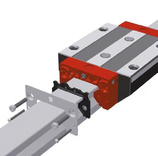
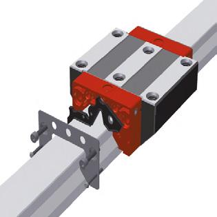
Cross wipers
Checking cross wipers
Check cross wipers regularly for wear and replace where required.
Replacing cross wipers in the case of MONORAIL MR
1. Leave carriages on the guideway.
2. Remove the upper and lower screws.
3. Remove front panel and accessories (where applicable) from the front plate (can be left on the guideway).
4. Disengage the cross wiper from the front plate and, to remove it, pull over the guide rail while holding the front plate in place.
5. Pull the new cross wiper onto the guide rail and press it into the front plate (taking care with the rotation lock).
6. Slide accessories and front panel back onto the front plate.
7. Tighten the screws. See 12.2 Screw tightening torgques on page 74
Fig.116
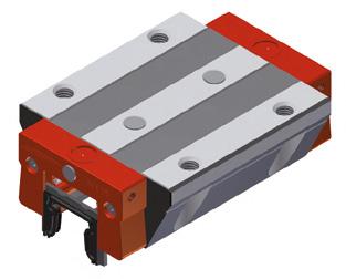
Replacing cross wipers in the case of MONORAIL BM front plates
In the case of MONORAIL BM, only the cross wipers in the front plate should be replaced.
The screws of the front plate must not be loosened during this process.
1. Use an assembly rail to transfer the carriage from the guideway.
2. Pull the defective cross wiper downward and out of the front plate housing.
3. Fully slide the cross wiper into the guideway groove of the front plate.
Ș The cross wiper will snap in audibly.
4. Remount the carriage onto the guide rail.
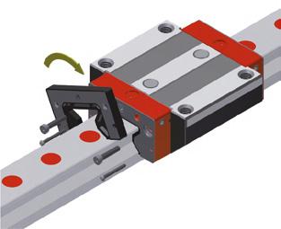
ZCV/ZBV additional wipers
Their flexibility enables additional wipers to be replaced directly on the guide rail. They can also be installed retroactively, e.g. should cross wipers become worn on the front plates of carriages that can not be removed from guide rails.
1. Loosen the screws on the front plate of the carriage.
2. Pull the additional wiper a few millimetres away from the front plate, holding the front plate in place.
3. Pull the wiper directly from the guideway and replace it (metal surface must face outward).
4. Pull the new additional wiper over the cross-section of the rail or thread it onto the guide rail end.
5. Press the wiper against the front plate, aligning it using the centring cone on its reverse side.
6. Ensure that the wiper is evenly positioned and tighten the screws (for max. tightening torque see „Screw tightening torques“ on page 75
NOTE: The lube connections on the front plate are sealed with set screws. During installation of the ZCV/ZBV additional wiper these set screws become covered. When screwing a lube nipple into the additional wiper, the underlying set screws must be removed.
Longitudinal wipers
Longitudinal wipers are attached firmly to the carriage or housing.
Checking longitudinal wipers
In order to identify damage to longitudinal wipers, fully dismount the carriage and carry out an optical check of the wiper lips.
Replacing longitudinal wipers
In the case of damage to longitudinal wipers that are firmly attached to the carriage or housing, the entire carriage must be replaced.
Metal wipers
Checking ASM/ABM metal wipers
• Check the frontal panel for mechanical damage and that its gap is positioned evenly with respect to the guide rail profile.
• Replace or readjust metal wiper in accordance with findings.
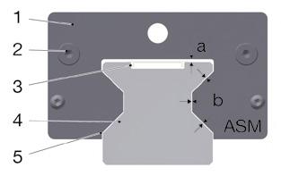
Replacing ASM/ABM metal wipers
1. Loosen the screws on the front plate.
2. Pull the wiper over the guide rail end.
3. Mount a new metal wiper over the guide rail end.
4. Tighten the fastening screws until the wiper can no longer be moved by hand.
5. Use a feeler gauge and relevant documentation to ensure an even gap between the guide rail and wiper edge.
6. Hold the metal wiper and tighten the fastening screws. For tightening torque, see „Screw tightening torques“ on page 75
7. Check the gap again after tightening the screws.
8. It must be ensured that the gap is maintained when the carriage is mounted onto a guide rail with an installed MAC cover strip.
1 ASM metal wiper
2 Fixing holes
3 MAC cover strip
4 MR guide rail
5 Surrounding gap
Gap dimensions:
a 0.9 mm ± 0.05 mm
b 0.25 mm ± 0.05 mm
When using an AMS guide rail, the ASM-A metal wiper must be used. This is shortened by 2 mm on both sides at the prism base (dimensions b).
This metal wiper can be identified by a frontal marking.
Rail covers
Rail covers include plugs, cover strips, and bellows. These are prerequisites for ensuring the proper functioning of the carriage seal system and one of the factors responsible for ensuring that the guideway provides an extended service life. Rail covers should be checked at regular intervals (at least every 6 months) for damage and wear, and replaced where necessary.
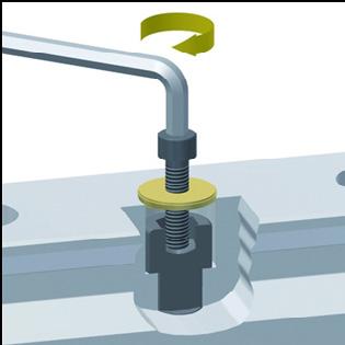
Plugs must be fitted flush with and parallel to the guide rail surface. Protruding or scratched plugs may cause damage to carriage wipers. Where plugs sit too deeply,
this may lead to the build-up of dirt in the guide rail fixing holes or to damage to carriage wipers caused by the sharp edges of these holes.
Checking plugs
Check plugs for dirt and swarf in the fixing holes or on the guide rail surface. Dirt and swarf that are not wiped away as the carriage passes over the guide are indicative of improperly functioning plugs. Plugs should be replaced in this case and carriage wipers checked.
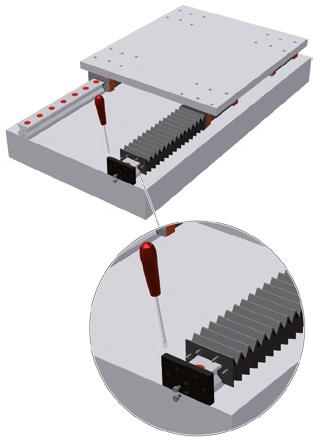
Cover strips
MAC/BAC cover strips
Cover strips must be positioned over the entire length of the guide rail cleanly and gap-free with a slight upward curve on the guide rail surface. The ends must be secured with a bracket or end pieces. Multi-part cover strips must not show any signs of a gap at the butt joint.
Checking MAC/BAC cover strips
Replace cover strips in the following cases:
• Cover strips are bent or scratched
• Cover strips have shifted longitudinally
• The cover strip has a raised end
• Cover strips are twisted
Replacing MAC/BAC cover strips
For cover strip replacement see „MAC/BAC cover strips“ on page 44.
FBM/FBB bellows
Bellows are fastened to the carriage with the adapter plate and to the guide rail end with the end plate using plastic rivets.
Checking bellows
Check bellows for damage such as tears or holes. Check that the bellows slide cleanly over the guide rails. In case of damage, the bellows must be replaced and the MONORAIL guideway also checked for damage or dirt and, where applicable, cleaned.
Replacing the bellows
1. Disengage the bellows from the fastening plates, using e.g. a flat screwdriver.
2. Loosen the fastening screws on the end plate.
3. Pull the bellows over the guide rail end.
4. Clean the guide rail.
5. Check the guide rail, plugs, and cover strip for damage.
6. Mount the new, pre-assembled bellows (with rivets) onto the guide rail.
7. Snap the rivets at the end of the bellows into the corresponding holes in the adapter plate.
8. Screw on the end plate.
9. Snap the rivets at the end of the bellows into the corresponding holes in the adapter plate.
10. Check the bellows for correct positioning and freedom of movement.
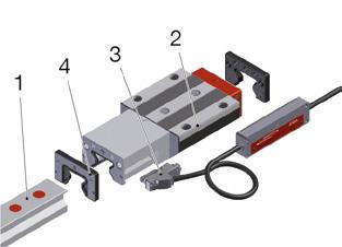
9.7 Spare parts - availability
All profiled linear guideways in the MONORAIL MR, BM, and AMS product groups consist of up to four logical sub-assemblies.
1 Guideway
2 Carriage, where applicable with housing for read head
3 AMS sensor unit
4 Accessories
The pre-assemblies are each subject to technical modifications that lead to new construction statuses. This means that the internal construction of the sub-assemblies may vary with respect to technology, materials used, number, and interaction of the constituent parts.
SCHNEEBERGER undertakes, following the delivery of MONORAIL systems, to make compatible sub-assemblies and therefore also compatible complete systems available that can be used in sub-assembly replacement. This enables full field service capability to be maintained for all products without sacrificing improveability. Parts from these sub-assemblies are only maintained and offered prior to the introduction of the new sub-assembly and delivered up to a limit of 1 year following its introduction. This means conversely that sub-assemblies replaced by new construction statuses are discontinued 1 year before expiry.
For sub-assemblies as a whole, SCHNEEBERGER offers compatible sub-assemblies which are identically designed with respect to the mechanical geometry of the guideway, collision cross sections, and connection dimensions for a period of 10 years following discontinuation of the product on the market. Any exceptions are communicated separately.
NOTE: The product and packaging material, consisting of plastics, metals, batteries, electronic components, wood, and lubricants, should be disposed of or recycled by the operator in accordance with locally applicable national or regional legislation.
Operating state display
The AMSA 3B, AMSA 4B, AMSD 3B/4B, and AMSABS measuring system versions are fitted with a service LED in the electronics housing of the read head that displays the different measuring system operating states.
LED
Red continuous
Red flickering
Red/green flickering
Red/green flashing
Green flickering
Green flashing
Red flashing
Green + red flashes
Red + green flashes
Red + green flashes
Green continuous
Error
Encoder defective, internal hardware error
External power supply outside tolerance
Internal sensor signal too low (< 60%)
Internal sensor signal too high (>140 %)
Encoder damaged, internal sensor voltage
> 5 V
Encoder damaged, internal sensor voltage
< 0.6 V
Not referenced, absolute position incorrect
Backup battery empty
At least 1 CNC error detected
Setting up DRIVE-CLiQ communication
System is working normally
Repair
Replace sensor
Check power cable from controller
Remove dirt: Read head, receiving housing, and measuring scale must be cleaned.
Check lubrication line connection. Replace read head.
Check lubrication line connection
Replace read head
Replace encoder
Replace encoder
Repeat referencing
Replace battery
Fix controller error as required
No action required
No action required
12.1 Dimensions of accessories
Dimensions of MRK/BRK plastic plugs
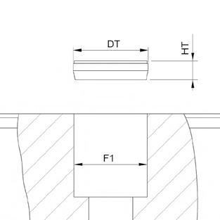
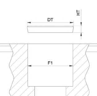
All dimensions in mm
Dimensions of MRS/BRS brass plugs
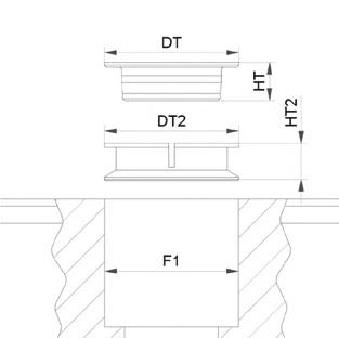
All dimensions in mm
Dimensions of MRZ steel plugs
Recommended screw sizes for dismantling MRS/BRS/MRZ
Sizes 35 - 100
All dimensions in mm
MWH/BWH assembly tool dimensions
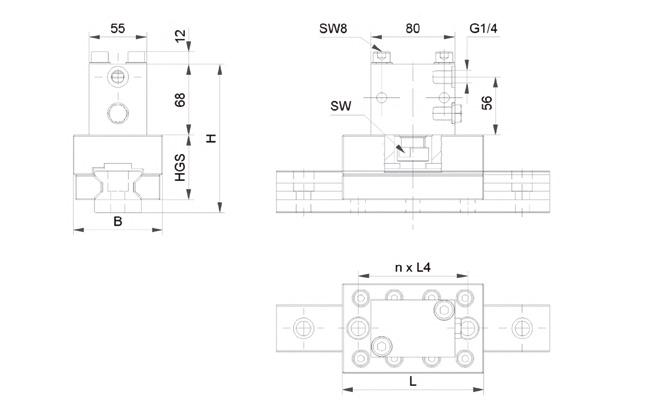
Dimensions of MAC/BAC cover strip
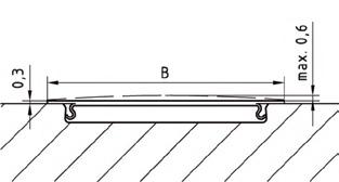
65 32
BAC 15 11
BAC 20 13
BAC 25 15
BAC 30 19
BAC 35 19
BAC 45 25
All dimensions in mm
Dimensions of steel securing bands
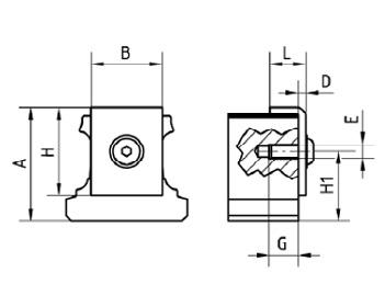
All dimensions in mm
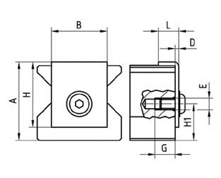
dimensions in mm
Tightening torques for guideways and carriages
DANGER!
Risk to life posed by falling machine elements!
In the case of sufficiently high loads, the screw connections are unable to prevent guideways or carriages e.g. from lateral sliding.
• Profiled linear guideways should be secured using all available mounting holes and/or threads.
• In the case of high loads, employ constructive measures to prevent guideways or carriages from sliding (e.g. lateral fixing).
• The recommendations of the screw suppliers must be followed and are always binding.
• Ensure that the material strength of the connecting structure is sufficient.
Risk to life posed by falling machine elements!
The friction coefficient μ can be reduced by up to half when greases are used and screws can fail during tightening.
• The torques must be reduced accordingly.
Lubrication of the fastening screws with grease and tightening using a torque wrench enables a more even preload force to be achieved. This results in a marked improvement of running accuracy.
µK = 0.12 (coefficient of friction in head in accordance with VDI 2230)
Tightening torques for front plates and additional wipers
See the table below for the maximum tightening torques for fastening screws for the front plates and additional wipers.
Risk to life posed by falling machine elements!
Screws for securing front plates are provided with threadlocker. The adhesive force of this is reduced by repeated screwing and unscrewing, which can lead to unwanted loosening of the screws during operation and loosening of the front plate.
• Do not re-use fastening screws several times.
• Ensure that new fastening screws are used when replacing components.
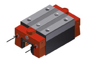
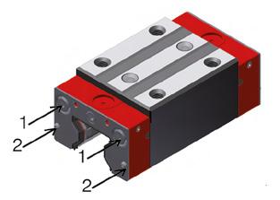
Maximum front plate tightening torque MAnz (Nm)
MONORAIL BM
MR
Permissible tightening torque for sealing lube connection fixing holes with:
• M3 set screws: 0.4 Nm
• M6 set screws: 0.8 Nm
Scope of Application
• The lubricating volumes for MONORAIL MR are also used for AMS 3B, AMSA 3L, and AMSABS 3B.
• The lubricating volumes for MONORAIL BM also apply for AMS 4B, AMSABS 4B, and BZ.
Lubrication with grease
Initial
NOTE
• SCHNEEBERGER recommends KP2K lubricating grease in accordance with DIN 51825 or GP00N/GP000N liquid grease in accordance with DIN 51826.
• The specified lubricant volumes are valid for both grease and for liquid grease.
• During greasing, move carriages three times their length several times.
• In the case of two lube connections per carriage, divide the specified quantity accordingly.
• When using GP000N liquid grease, take the installation orientation of the axis into account (separated connections).
Lubrication with oil
Initial lubrication, amount of oil per carriage [cm3]
• SCHNEEBERGER recommends CLP (DIN 51517) or HLP (DIN 51524) mineral oil with a viscosity range between ISO VG32 and ISO VG100 (DIN 51519).
• CGLP bed track oils can be used up to ISO VG220.
General information on lubrication
• Inject the entire oil quantity in a single impulse or in several impulses in short succession while the carriage is being moved.
• In the case of vertical installation of the carriage, the lube connection must be installed in the upper front plate.
• In the case of two lube connections per carriage, divide the specified quantity accordingly.
• During greasing, move carriages three times their length several times.
• Take the installation orientation of the axis into account (separated connections).
• Where necessary carry out lubricating/cleaning strokes.
• Lubricate prior to shutdown/recommissioning
Lubricating volumes for SPL refilling
Refilling SPL-MR
Refilling SPL-BM
1 x SPL in cm3
NOTE: The SPL must be refilled using KLÜBER Lamora D 220 oil. SCHNEEBERGER GmbH Höfen/Enz assumes no liability for refilling using other lubricants.
12.4 Cable bending radi
SWITZERLAND SCHNEEBERGER AG Lineartechnik St. Urbanstrasse 12 4914 Roggwil/BE
+41 62 918 41 11
+41 62 918 41 00 info-ch@schneeberger.com
CHINA SCHNEEBERGER Precision Motion System Asia Pacific 1/F, F Building, Hongfa Science Park, Tangtou Community, Shiyan Street, Boan District, Shenzhen, P.R.C 518108
深圳市宝安区石岩街道塘头社区 宏发科技园F栋一层 邮编 510108
+86 755 3352 5881 info-cn@schneeberger-sz.com
GERMANY SCHNEEBERGER GmbH Gräfenau 75339 Höfen/Enz
+49 7081 782 0 +49 7081 782 124 info-d@schneeberger.com
CHINA
SCHNEEBERGER (Shanghai) Co., Ltd. Rm 606, Shang Gao International Building No. 137 XianXia Road 200051 Shanghai
施耐博格(上海)传动技术有限公司 上海市长宁区仙霞路137号 盛高国际大厦606室 上海 200051
+86 21 6209 0027/37 +86 21 6209 0102 info@schneeberger-sh.com
SCHNEEBERGER COMPANIES
JAPAN
Nippon SCHNEEBERGER K.K. Itoyu Bldg Toranomon 7F 3-20-5 Toranomon, Minato-ku Tokyo 105-0001
日本シュネーベルガー株式会社 〒105-0001
東京都港区虎ノ門3-20-5 クレイン虎ノ門ビル7階
+81 3 6435 7474 +81 3 6435 7475 info-j@schneeberger.com
SCHNEEBERGER SALES DEPARTMENTS
AUSTRIA AND SOUTH EAST EUROPE +41 62 918 41 11 info-a@schneeberger.com
POLAND, SLOVAKIA, CZECH REPUBLIC +420 6 0278 4077
info-cz@schneeberger.com
BENELUX +31 6 5326 3929
info-nl@schneeberger.com
RUSSIA, BELARUS, UKRAINE +7 985 960 85 53 +38 050 407 6789 +37 529 860 0410 info-ru@schneeberger.com
ITALY SCHNEEBERGER S.r.l. Via Soldani 10 21021 Angera (VA)
+39 0331 93 20 10 +39 0331 93 16 55 info-i@schneeberger.com
KOREA
SCHNEEBERGER Korea Ltd. 5F-E01, 10 Chungmin-ro, Songpa-gu, Seoul, 05840 Republic of Korea
슈니베거코리아 유한회사 05840 서울시 송파구 충민로 10 가든파이브 툴관 5층 5-E01
USA SCHNEEBERGER Inc. 44 Sixth Road, Woburn, MA 01801-1759
+1 781 271 0140 +1 781 932 4127 info-usa@schneeberger.com
SINGAPORE SCHNEEBERGER Linear Technology Pte. Ltd. 38 Ang Mo Kio Industrial Park 2 #01-04, Singapore 569511
INDIA Schneeberger India Pvt. Ltd. 188/4, Bommasandra Industrial Area, Bommasandra, Bangalore 560099
India
+91 22 6461 0646 +91 22 6461 1756 info-in@schneeberger.com
TURKEY
SCHNEEBERGER LINEER TEKNOLOJİ
Tic. ve Ltd. Şti. Ataköy 9. Kısım Mah. Yüzücü Talat Yüzmen
Sokak No:6 Yunus Emre Sitesi S3 A-Blok D:2 Bakirkoy 34158 Istanbul Turkey
+ 82 (0)2 554 2971 +86 21 6209 0102 info@schneeberger-sh.com
+ 65 6841 2385 + 65 6841 3408 info-sg@schneeberger.com
PROSPECTUSES
COMPANY BROCHURE CUSTOMIZED BEARINGS GEAR RACKS
Linear bearings and Recirculating units MINERAL CASTING SCHNEEBERGER MINISLIDE MSQscale
CZECH REPUBLIC SCHNEEBERGER Mineralgusstechnik s.r.o Prumyslový park 32/20 350 02 Cheb – Dolní Dvory
CHINA SCHNEEBERGER Changzhou Precision Systems Co. Ltd. No. 137 Hanjiang Road 213022 Changzhou
施耐博格(常州)测试系统限公司 汉江路137,常州新区,常州 213022
+420 354 400 941 +420 354 400 940 info-mineralguss@schneeberger.com
+86 519 8988 3938 info-mineralguss@schneeberger.com
GERMANY A.MANNESMANN MASCHINENFABRIK GmbH Bliedinghauser Str. 27 42859 Remscheid +49 2191 989-0 +49 2191 989-201 mail@amannesmann.de
DENMARK, SWEDEN +31 6 5326 3929
info-nl@schneeberger.com
SPAIN, PORTUGAL ANDORRA +34 69 559 05 99
info-es@schneeberger.com
FRANCE +33 6 33 12 14 26
info-nl@schneeberger.com
MINI-X MINIRAIL / MINISCALE PLUS / MINISLIDE MONORAIL and AMS profiled linear guideways with integrated measuring system MONORAIL and AMS application catalog POSITIONING SYSTEMS
A.MANNESMANN A member of SCHNEEBERGER linear technology
GREAT BRITAIN +44 74 63 89 85 08
info-uk@schneeberger.com
www.schneeberger.com