02 | ACADEMIC WORKS 01 | PART 1 PROFESSIONAL WORKS CV 03 | PART 2 PROFESSIONAL WORKS 04 | PART 2 TECHNICAL WORKS 05 | OTHER WORKS CONTENT
2019-2023 Regeneration of the Market Area in Belfast Large scale urban design Commercial | Residential | Workspace | Mixed-use Technical skills Model Making | Visualisation | Photography
SELECTED WORKS
RONGZHEN JIANG
Assistant
EDUCATION
A highly self-motivated part 2 architectural assistant with 2 years practical experience in both large-scale international architecture firm and small-scale UK based architecture firm.
Worked in wide varieties of projects including large-scale urban design, residential, commercial, industrial and mixed-use projects.
Have good understanding of UK architecture practice and excellent knowledge of UK planning system and building regulations. Highly proficient in essential 2D and 3D architectural software and highly skilled in digital modelling and visualsation.
Queen’s University Belfast
Master of Architecture (ARB / RIBA Part 2)
Graduated with distinction in dissertation (Humanistic Care in the Planning of a Rapid Developing City -A Study of Shenzhen, China)
Newcastle University
BA (HONS) Architecture (ARB / RIBA Part 1)
rjiang02@qub.ac.uk
(+44) 7366678878
Belfast, UK
2020-2022
gmp Architekten
Landmark Building, Unit 3006 No. 4028 Jintian Road
Futian District
2016-2019
518035 Shenzhen, China
EMPLOYMENT
Part 2 Architectural Assistant
Campbell Architects
Involved in a series of small to large scale UK-based residential, commercial, industrial and mixed-use projects from stage 0-4.
Part 1 Architectural Assistant
Gerkan, Marg and Partners
Involved in a series of China-based large-scale urban design project. Developed strong skills in conceptual and technical stages of large-scale project.
PROJECTS EXPERIENCE
Commercial / Industrial
Ickenham Office and Warehouse (£32m) | Stage 0-4
Royal Northern Ireland Yacht Club (£ N/A) | Stage 0-3
Residential
Osborne Garden Housing Development (£40m) Stage 0-4
Astley Housing Development (£ N/A) | Stage 0-2
Trory Lodge House Restoration (£250k) | Stage 0-4
Mixed-use
446 Fulham Road (Competition)
Large-scale Urban Design
Guangzhou Xilang Transportation (Competition)
Huangang Technology Park (Competition)
Chengdu Future City (£7.2 bn.)
Xiongan Railway Station (Competition)
Jun 2022 - Present
Shenzhen, 27.02.2020
Recommendation letter of Jiang Rongzhen
Managing Directors Prof. Dr. h.c. mult. Dipl.-Ing. Meinhard von Gerkan Prof. Dipl.-Ing. Volkwin Marg Hamburg Court
Sep 2019 - Sep 2020
To whom may concern,
It is my pleasure to write this letter of recommendation for Mr Jiang Rongzhen.
Jiang Rongzhen has been an intern with our Shenzhen office since Oct. 8th 2019, and expectedly until Oct. 7th 2020. His internship includes working in AutoCAD 2D as well as in sketchup/ Rhino 3D.
Ickenham, England Belfast, Northern Ireland
Herne Bay, England Brighton, England Holywood, Northern Ireland
London, England
Guangzhou, China Shenzhen, China Chengdu, China Hebei, China
During his internship, Jiang Rongzhen successfully contributed to Guangzhou Xilang transportation Hub project and Xiong’an 2-station design project. He was included to various work processes such as 3D modelling of urban spaces, highrise landmark buildings, facade studies, as well as 2D urban design layout. In the later phase of the competition, he did analysis diagrams, Indesign brochure layout etc.
C. R. No. HR B 79 167
T: +49.40.88 151 0
F: +49.40.88 151 177
E-mail: Hamburg-E@ gmp-architekten.de
CYTS Plaza, No. 1212 No. 5 Dongzhimen South Avenue Dongcheng District 100007 Beijing, P.R. China

LANGUAGE
English | Chinese Mandarin
SKILLS PROFICIENCY REFERENCES
Adobe Photoshop
Adobe InDesign
Adobe Illustrator
Adobe Premeier Pro
Mr. Christopher Campbell
SketchUp
Revit Enscape V-Ray
AutoCAD
Physical Modelling
Laser Cutting MS. Office
Campbell Archtiects Director | chris.campbell@campbellarchitects.co.uk


Dr. Agustina Martire
Queen’s University Belfast Design Tutor a.martire@qub.ac.uk
Mr. Zhicong Chen
gmp senior Architect Cyruschan@qq.com
Jiang Rongzhen managed very well to understand requirement of different aspects and involved himself very well into the team work very quickly. He has known the best of consciousness towards the design goals as well as a very high degree of responsibility for his work. Jiang Rongzhen did his job trustfullly and with very high efficiency during the whole internship. In direct cooperation with him, He proved to be a very fast learner and an overall friendly, intellegent, open minded person and a creative, smart team player. He was easily able to understand comments given by the team leader and integrate them to a quick and professional result. With his support, we have won the first prize of Guanghou Xilang Hub international competition! As an intern, Jiang Rongzhen worked very actively and effectively in cooperation with the other professional architects.
If any further information about Mr Jiang Rongzhen is required, please do not hesitate to contact me.
Best regards
Chen Zhicong Chief Architect gmp Shenzhen
E-mail: Beijing@ gmp-architekten.de 5 1212 100007 : Beijing@ gmp-architekten.de
QingKe Mansion, 10 th Floor No. 138 Fen Yang Road Xu Hui District 200031 Shanghai, P.R. China
E-mail: Shanghai@ gmp-architekten.de 138 10 200031 : Shanghai@ gmp-architekten.de
Landmark Building, Unit 3706 No. 4028 Jintian Road Futian District 518035 Shenzhen, P.R. China
E-mail: Shenzhen@ gmp-architekten.de
DRIVING LICENCE
Full UK Licence
4028
3706 518035 : Shenzhen@ gmp-architekten.de
International
gmp
GmbH architects and engineers gmp
gmp International GmbH Landmark Building Unit 3706 No.4028 Jintian Road 518035 Shenzhen gmp 4028 3706 518035
Part 2 Architectural
01 | PART 1 PROFESSIONAL WORKS
Guangzhou Xilang Transportation Hub (Competition)
Location:
Category:
Client:
Project Year:
GFA:
Work Involved:
Guangzhou, China
Transportation Hub, Commercial Guangzhou Metro Group Co., Ltd
2019
1,600,000 sqm
Conceptual development, Modelling, CAD drawings, Diagrams, Competition packages, Attending key meetings
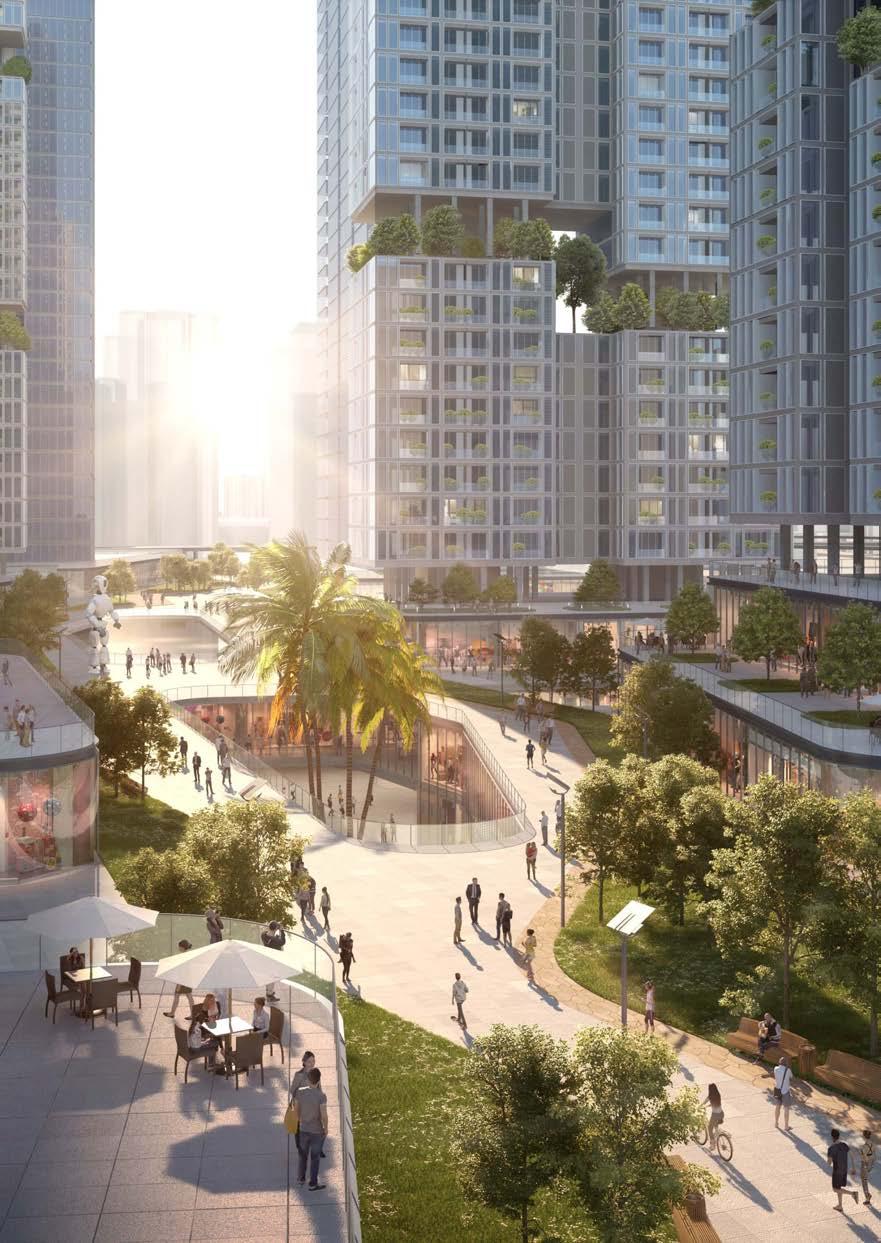
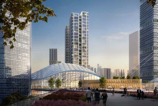
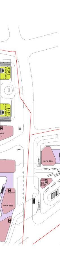
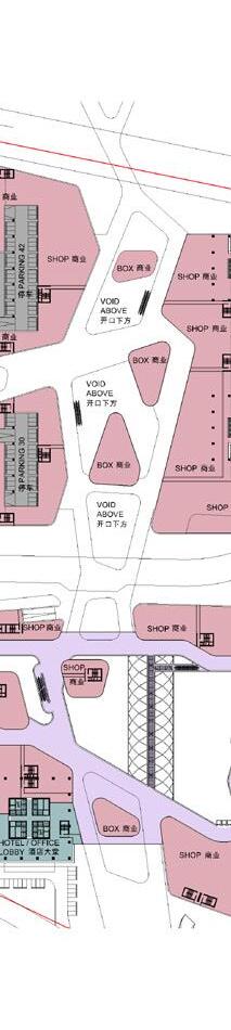
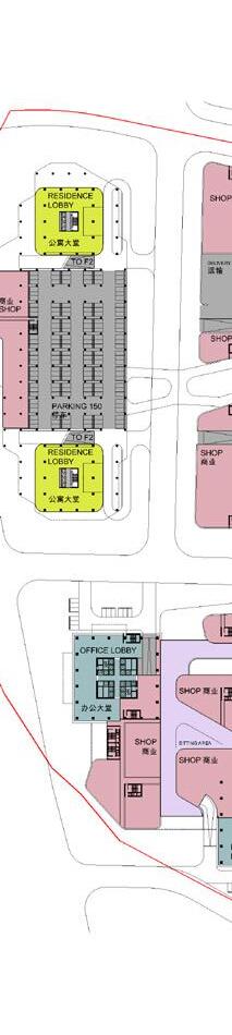
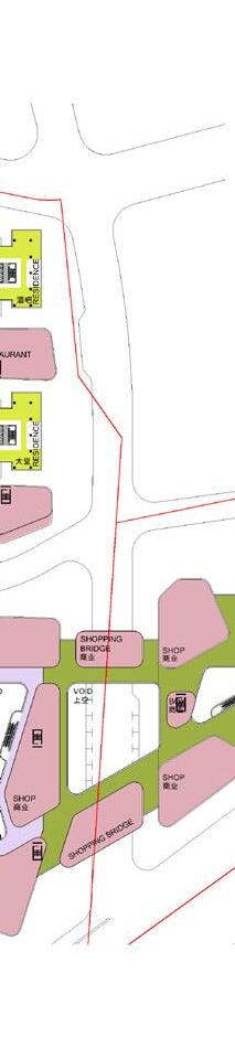
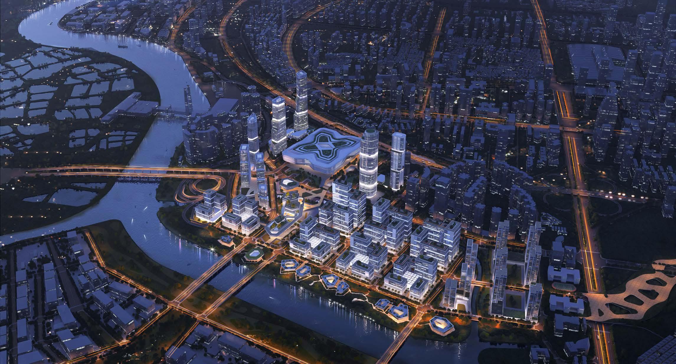
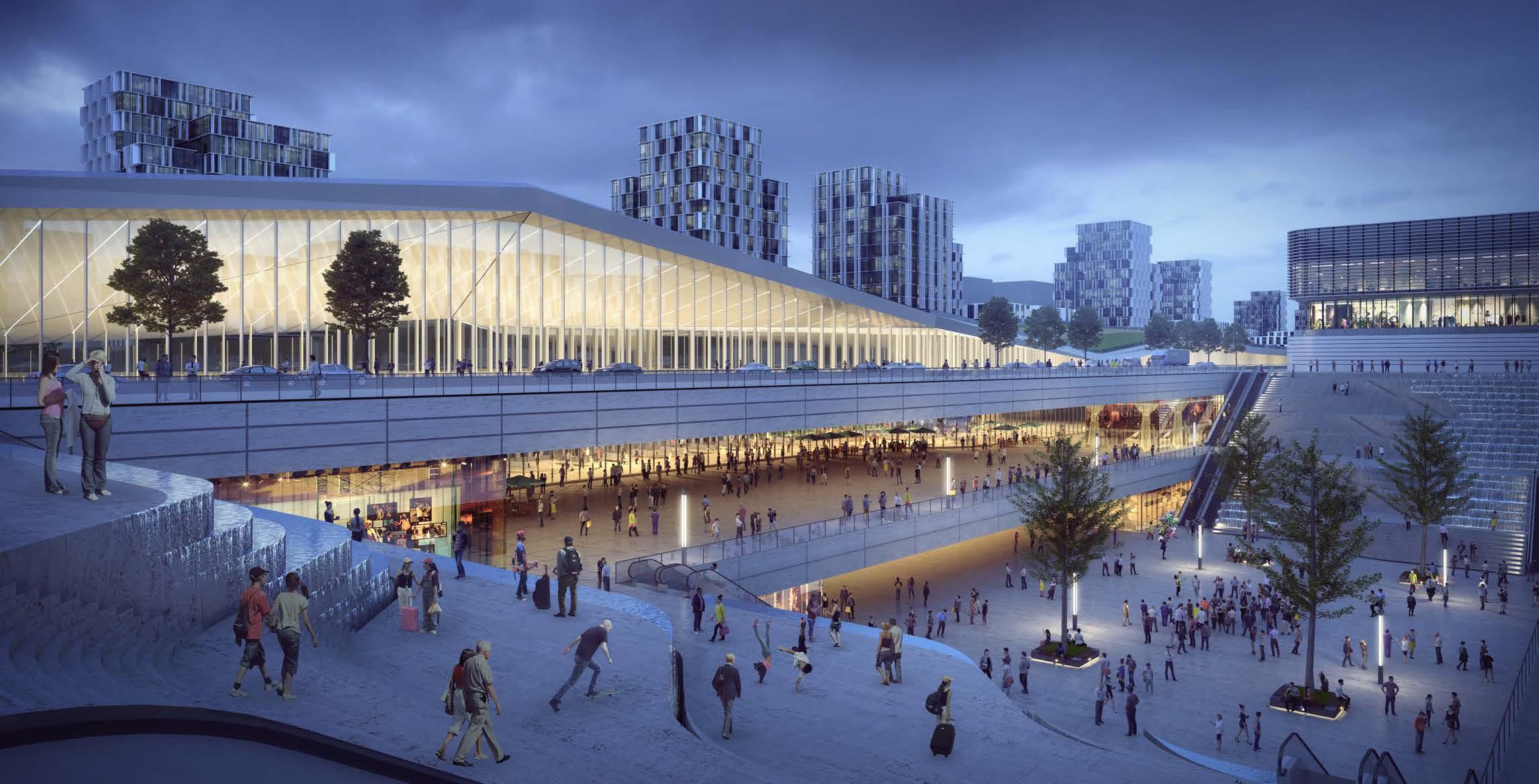
Guangzhou Xilang Transportation Hub development is a large scale urban design competition for the client Guangzhou Metro Group. The site is located at the border of one of the largest Chinese city Guangzhou and tier 2 city Foshan. It is within the Pearl River Delta, one of the most developed area in China.
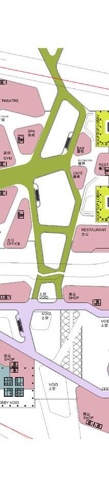
The masterplan provided an overall development and improvement strategy for the 3.3 square -kilometre area of Xilang District, promoting the renovation of surrounding areas from multiple aspects, such as landscape, dynamic community, integration of industry and urban space, and integration of transportation station and city. The urban design proposal aimed to create a regional business centre in Liwan District by developing a complete open space system, introducing a pedestrian-friendly urban space, and integrating a comprehensive public transportation system into the urban fabric.
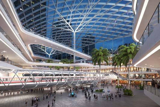
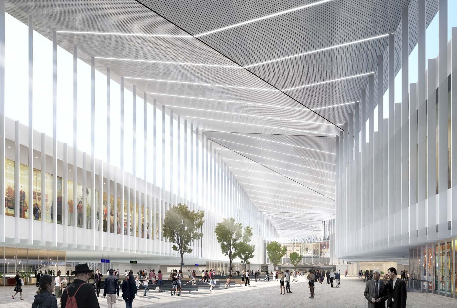
The scheme uses an elevated platform system to organically connect different functional blocks within the site, at the same time, integrate it with the surrounding urban public space. The concept of ‘Integration of transportation station and urban space’ facilitates the metro transfer hall and commercial space within a large atrium space under the big roof.
Work involved:
Concept development
AutoCAD drawings
SketchUp model making Diagrams drawings
Competition package
DESIGN CONCEPT
The concept for the master plan is based on the ‘Banyan Tree’ which is one of the most typical trees in Guangzhou. It symbolizes the spirit of people in Guangzhou, like the roots of the Banyan tree can grow in the toughest conditions such as the gap of the wall. The platform inspired by the Banyan tree roots connect different functions from south of the site (station area) to north (commercial & residential area).
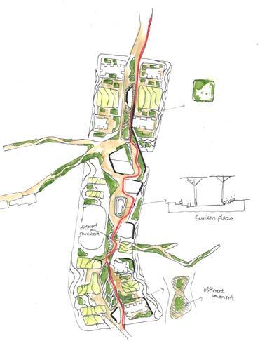
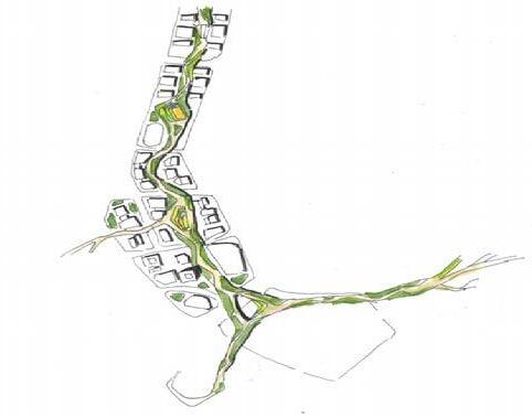

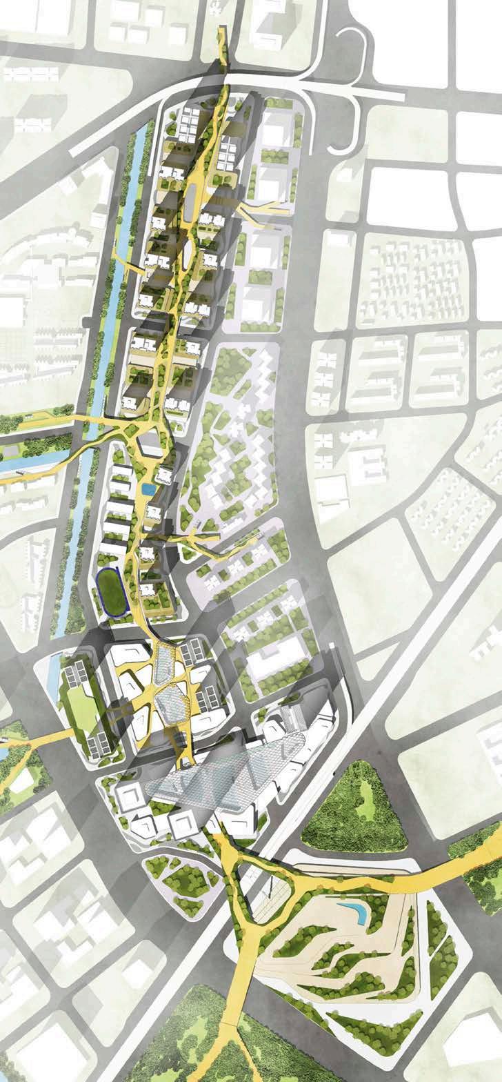
Site plan Conceptual sketch
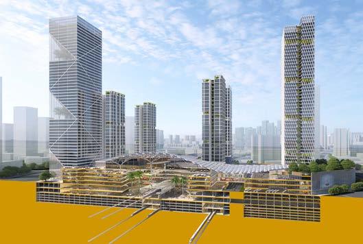
TRANSFER HALL
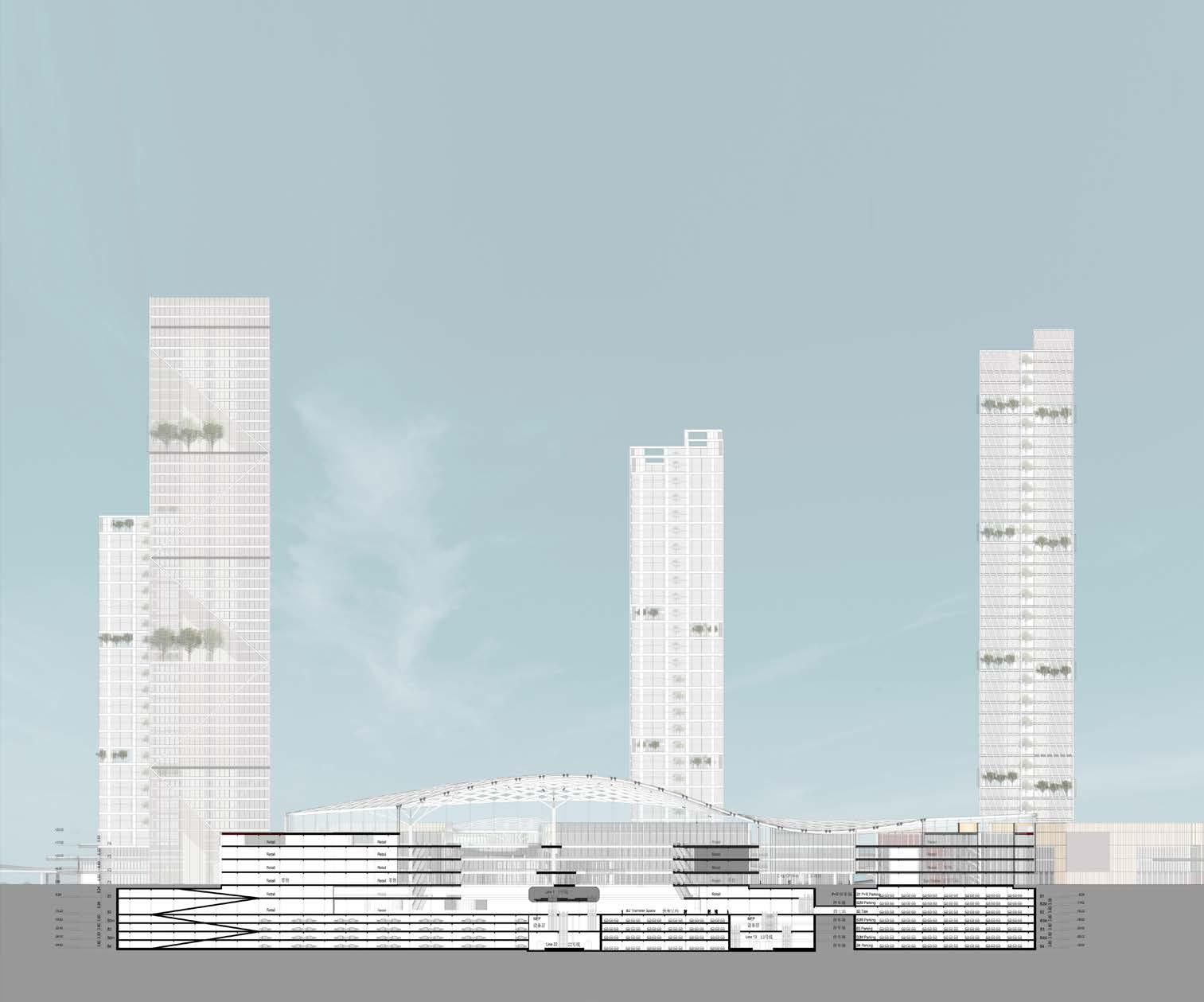
The station-urban space integrated concept was achieved by integrating the transfer hall, transportation facilities and commercial area into a big space covered by a massive roof. Floating metro platform for metro line 1 exposed in the transfer and shopping space, as a unique feature for the transportation hub.


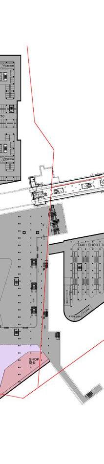


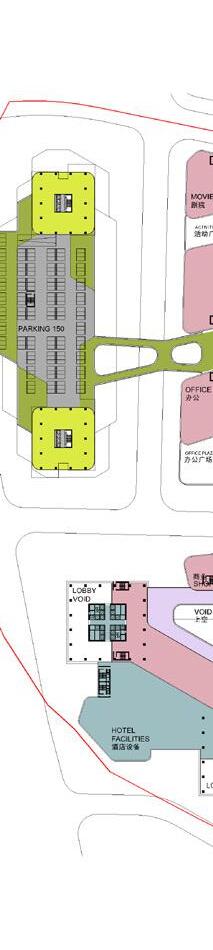

 Upper floor plan
Transfer hall section
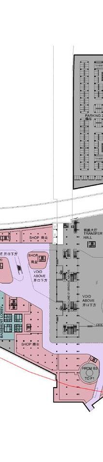
Ground floor plan
Transfer hall floor plan
Upper floor plan
Transfer hall section
Ground floor plan
Transfer hall floor plan
| PART 1 PROFESSIONAL WORKS
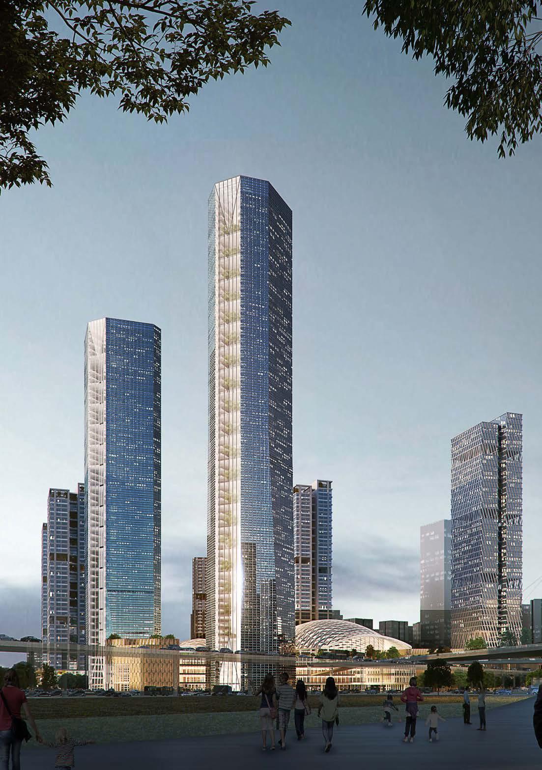
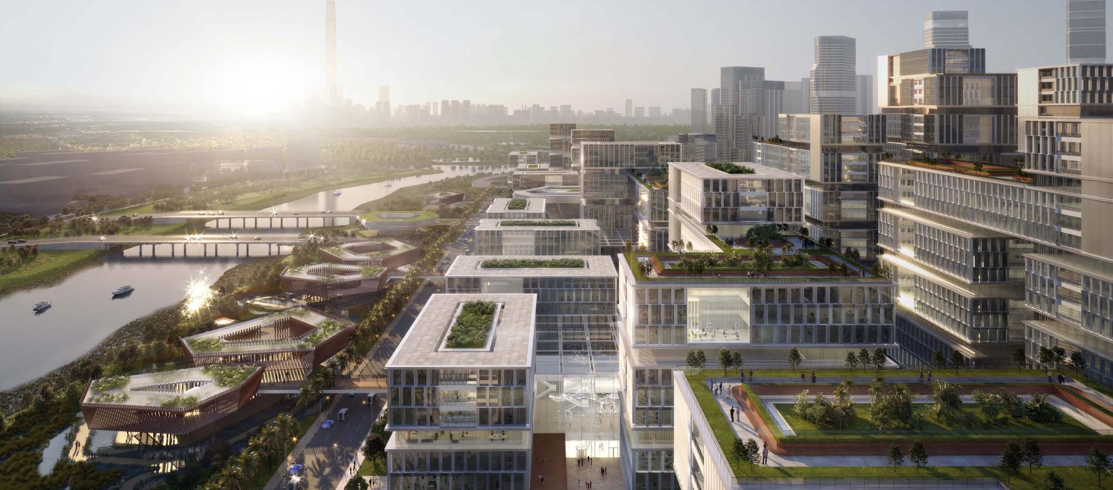
Shenzhen Technology Park
Location: Category:
Client: Project Year:
Shenzhen, China Urban design Shenzhen City Council 2020
Work involved:
Concept development
AutoCAD drawings
SketchUp modelling Diagrams drawings
Competition package
01
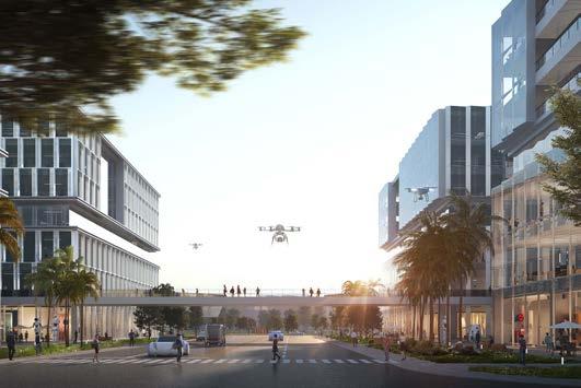
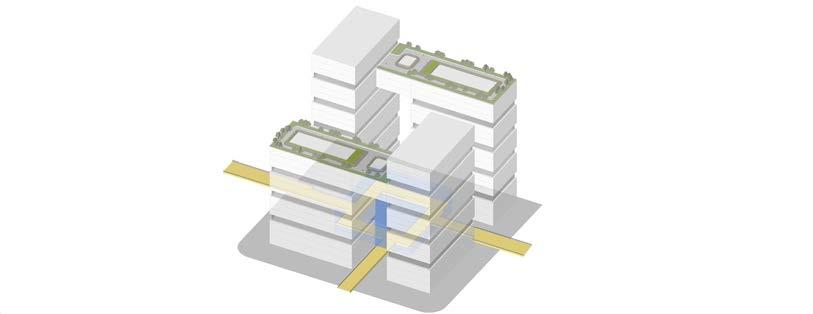
INNOVATION CLUSTER
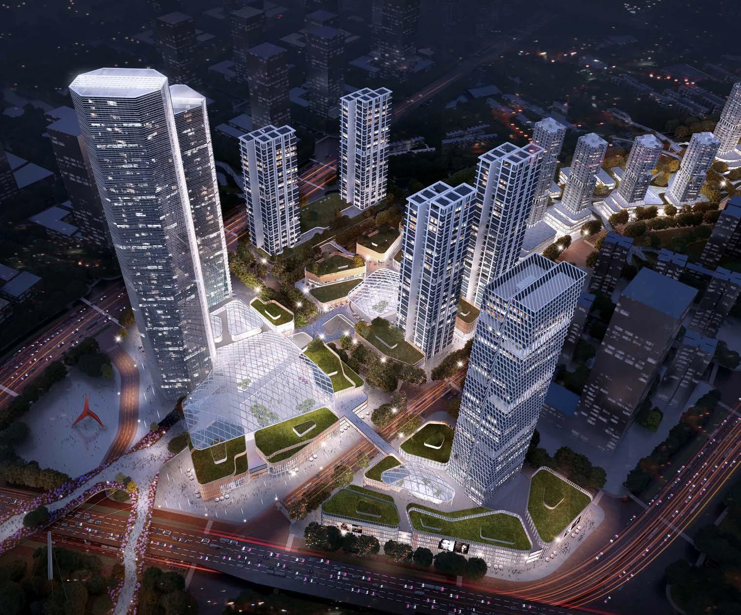
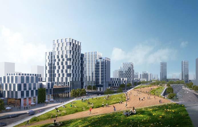
The innovation park located in the east of the site includes 8 innovation clusters with each innovation cluster consisted by 4 tower blocks in different height to provide unobstructed view to Shenzhen Wetland Conservation area. The 8 clusters are connected with each other through the linking platform on the first floor level extended form the shared indoor communal atrium space in each cluster.
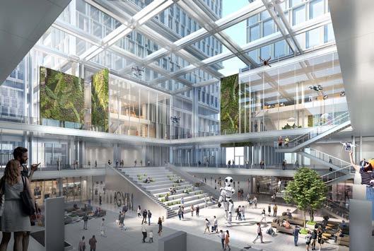
研发者沙龙 Developer’s Salon 研发者沙龙 Developer’s Salon 空中花园 Sky Garden 二层云平台 Cloud Platform (2F) 研发者沙龙 Developer’s Salon 空中花园 Sky Garden 二层云平台 Cloud Platform (2F) 研发者沙龙 Developer’s Salon
Xiongan Train Statation and Surrounding Area Urban Design
01
| PART 1 PROFESSIONAL WORKS Location: Category: Client: Project Year: Hubei, China Urban design Xiongan City Council 2020
Work involved: Concept development AutoCAD drawings Visualization SketchUp model making Diagrams drawings Design code Planning package
Work involved: Concept development AutoCAD drawings SketchUp modelling Diagrams drawings Competition package
TRAIN STATION + COMMERCIAL SPACE
F1 B1 Xiong’an Intercity Railway F1 B1 B2 雄安城际站及小里站周边建筑设计 Xiong’an Intercity Railway Station, Xiaoli Railway Stations, and Their Surrounding F1 B1 B2 B3 雄安城际站及小里站周边建筑设计 B1 B2 B3 B4 Train station floor plans - Level B3 Train station floor plans - Level B2 Train station floor plans - Level B1 Train station floor plans - Level 00
A three-dimesnional space system was formed by the folding roof design on the train station with elevated outdoor walkways and the sunken plaza to the south
02 | ACADEMIC WORKS
Regeneration of the Market Area in Belfast
Location:
Category:
Project Year:
Belfast , Northern Ireland
Mixed-use, Urban Farm, Residential 2021-2022 (Master research and design project)
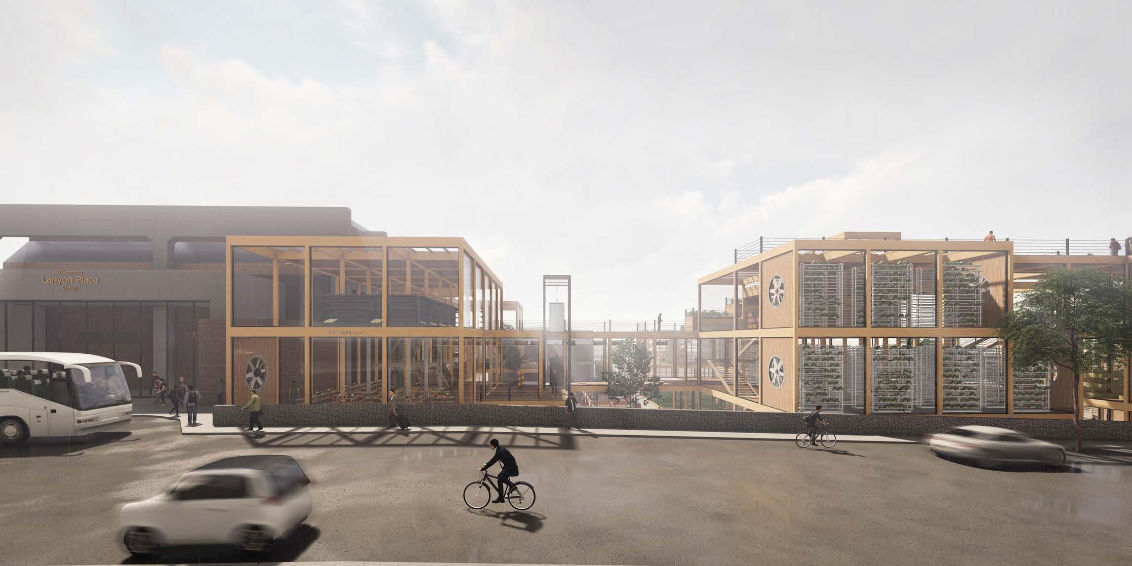
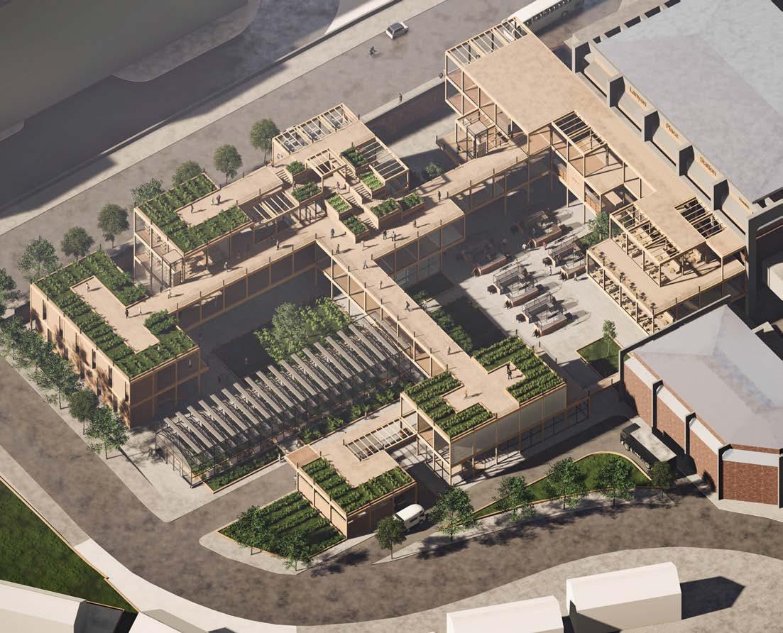
In the first year of my master, my studio project was about the sustainability aspect of the built environment. My design project focused on the issue of high food carbon footprint in the current food industry. Trying to reduce the food carbon footprint by shortening the food supply chain. This was achieved by localizing the food production. Therefore, my MArch 1 project was an urban farm located next to the main railway station in Belfast – The Lanyon Station. The urban farm aims to provide residents with easy and efficient access to local produced farm food.
At the same time, my MArch 1 humanity dissertation research focused on the social aspect of the built environment. It discussed the under considered humanistic care in the planning of a rapid developing city, use the Chinese city, Shenzhen as example. It argues that the humanistic care to migrants and marginalized residents was not considered sufficiently in city’s rapid development. And stressed the responsibility of the planning authorities to improve the consideration for marginalized groups in the planning of a city.
In this year, my research and design project are based on the MArch 1 urban farm project. It focused on the sustainability of the built environment both environmentally and socially.
THE FARM
‘The Farm’ is a possible solution to deal with the issues of urban food security, affordability and sustainability by localising the food production. The site was chosen at an empty plot next to the Lanyon Place (Belfast Central Station) for easy access by local and surrounding residents. The farm will also utilise the railway system to deliver the food it produced to the surrounding towns and cities.
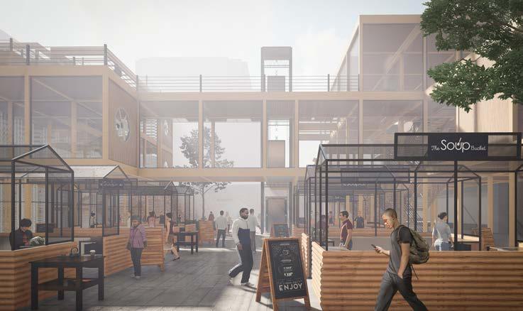
The project include food market, food collection, local food
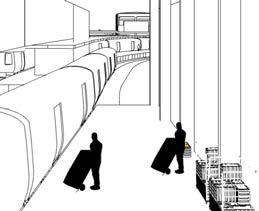
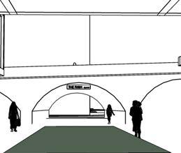
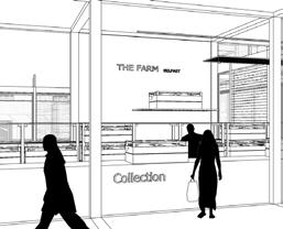
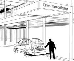
restaurant, local food research centre & lab, farm stay, farms, warehouse and urban farming experience centre.
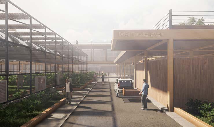
The project will work as a local food production and supply system to provide safe, cheap and low carbon embodied food for Belfast and surrounding area, meanwhile to add cultural and educational value to the community.
02 | ACADEMIC WORKS
Regeneration of the Market Area in Belfast
Location:
Category:
Project Year:
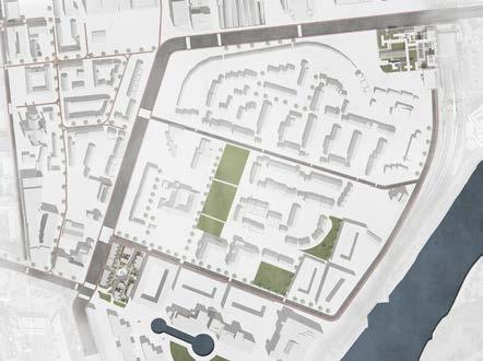
‘The Market’ is an urban design project in central Belfast. It particularly focused on the social sustainability of the built environment.
Belfast , Northern Ireland
Mixed-use, Urban Farm, Residential
2021-2022 (Master research and design project)
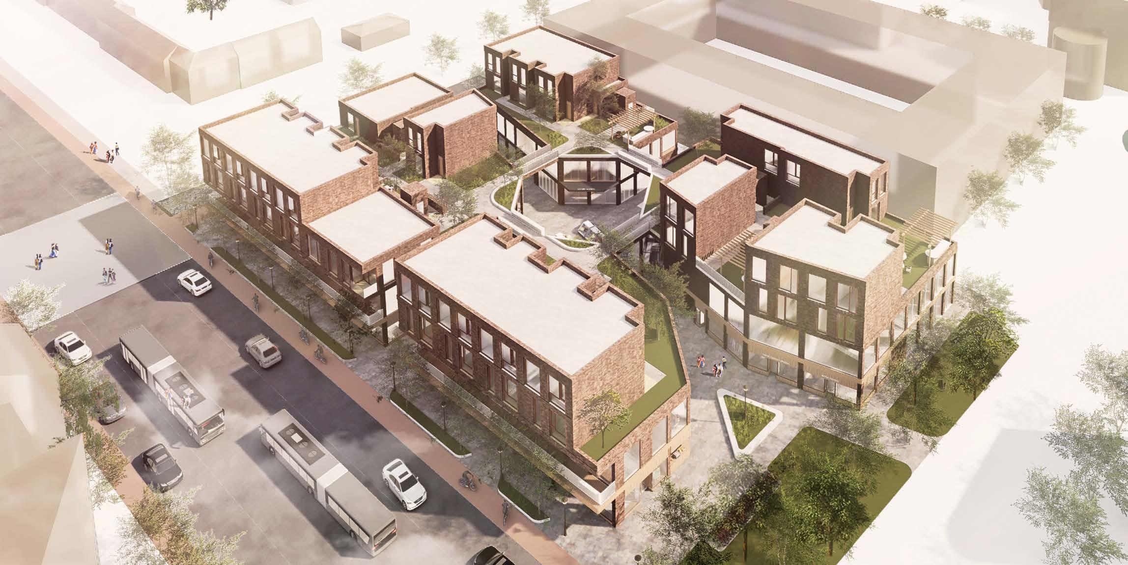
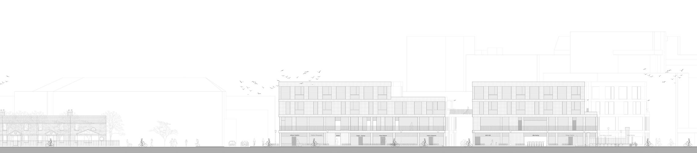
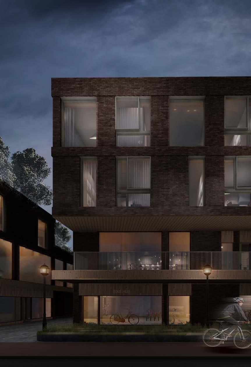
The Market project aimed to offer the surrounding communities a very vibrant social environment with strong sense of belongs, sense of communities and economical resilience which the place lost due to the gentrification of the area since commercialisation started in 1980s.
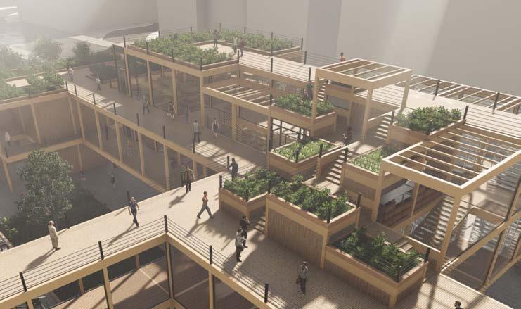
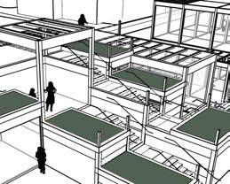
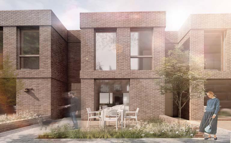
The scheme provided spaces for local small business with venue for market activities such as flexible market space in the central of the scheme, the housing units on the top of commercial retail units with communal linkage on the second floor level which response to the previous building typologies before the gentrification of the area.
Housing Units


2 storey 2-bedroom housing unit on the first floor level with direct access to private front ‘garden’ and communal space.
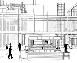
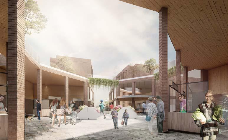
Central Market Space
The semi-open central market space can be used flexibly. It is the space for daily market trading, community event and exhibition.
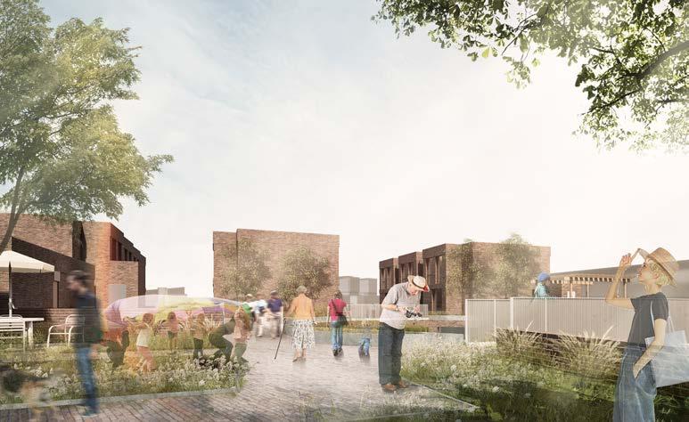
First Floor Platform
Open-air first floor platform connecting 4 blocks and providing outdoor communal space for residents.
03
Level
02 Level 00 Level 01
Level
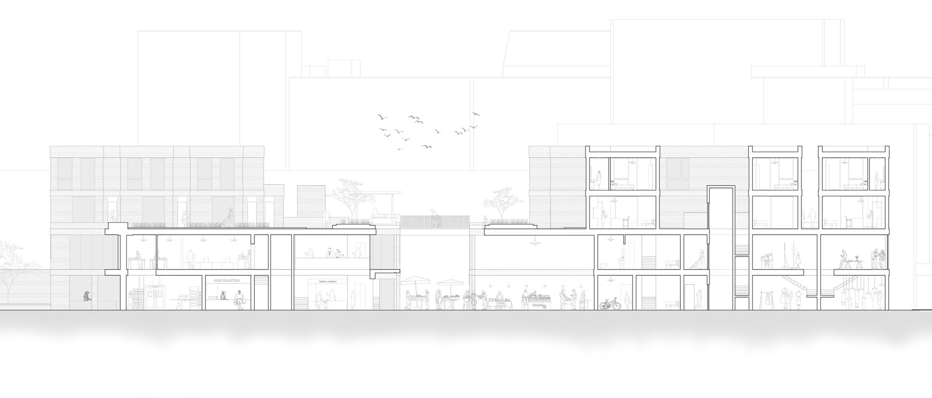


Loading area for receiving the food from urban farm and loading the processed food delivering to other area. Cookery school kitchen with a view into the food production underneath Communal BBQ corner in the centre of the second floor roof platform Linking bridge connecting four residential blocks on the second floor. Level Living room, kitchen and reading room on the lower floor of the duplex housing, with access to the front garden. Two bedrooms on the upper floor of the duplex housing. Software Used: SketchUp Enscape Photoshop Double height space for the entrance and reception space of the cookery school. Food collection point for collecting the food processed and packaged in the food production space. Food production for processing and packaging the food produced from the urban farm. The vertical circulation core for residents to access their housing through roof platform on the second floor. Retail space on ground floor for local small business, each unit comes with workshop space on the first floor. Section Site elevation
Vapour control barrier
160 mm PU thermal insulation
Vapour control barrier
200 mm reinforced concrete roof 10 mm mineral plaster
3 mm sheet anodized-aluminium
Parapet-wall covering Vapour control barrier
40 mm thermal insulation
215/102/50 mm facing brick skin
Galvanized-steel wall ties
100 mm cavity
Bituminous-felt seal

140 mm mineral-wool thermal insulation
180 mm reinforced concrete wall 10 mm mineral plaster
30 mm oak parquet
50 mm screed separating layer
200 mm reinforced concrete floor
20 mm ipe boarding 50/60 mm squared timbers
PVC layer on stilts two-layer bituminous felt seal
100 mm polyurethane thermal insulation
Vapour barrier
200 mm reinforced concrete floor
10 mm mineral plaster
Suspended timber ceiling
30 mm oak parquet
30 mm thermal insulation
Trowelled smoothed polythene separating layer
200 mm reinforced concrete floor
Two-layer polythene separation
120 mm XPS thermal insulation
Bituminous sealing layer
50 mm blinding layer
1 2 3 4
6
5
1 2 4 3 5 6 Technical details Street view
Work involved:
Concept development
AutoCAD drawings
Visualization
SketchUp model making
Diagrams drawings
Design code
Planning package
| PART 2 PROFESSIONAL WORKS
Large-scale Residential Development
Location:
Category:
Client: Project Year: Project Budget:
Herne Bay, England Residential Kitewood 2022 40 million
Background Osborne development is a large-scale residential project appointed by the client Kitewood Estates Private Development in relation to the Reserved Masters Application for land south of Osborne Gardens, Hillborough, Herne Bay. It is part of the major extension to the coastal area of Herne Bay.
Design proposal
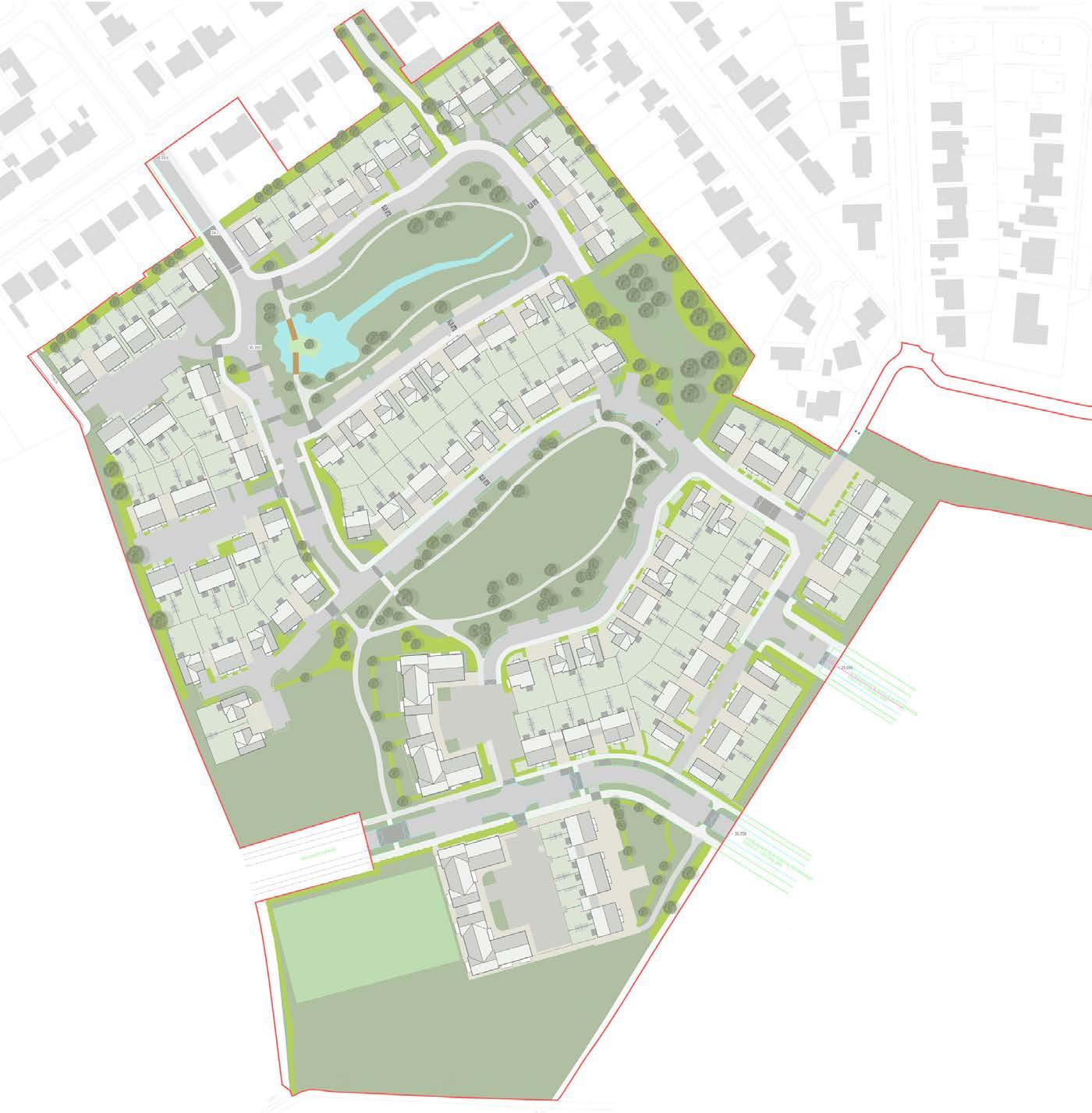
The proposal includes the development of 180 dwellings on greenfield site part of wider master plan of circa 3000 houses. The site layout follows the approved Land Use Parameter Plan which gives structure to the density of homes within the site. Two character areas are proposed within the site, which are defined to reduce
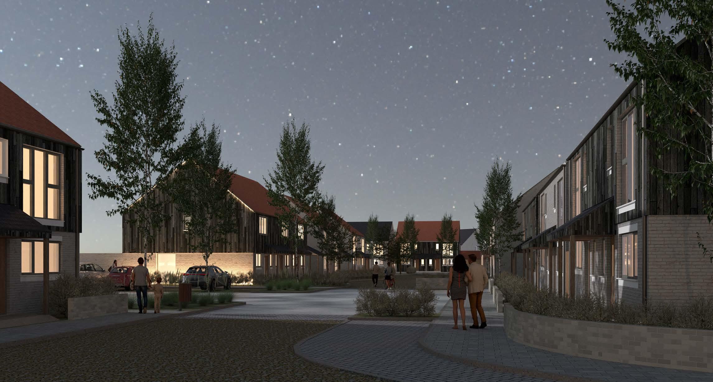
the scale of the residential development, relative to the wider Masterplan.
The areas are split strategically by a generous green space and linked by a single road to encourage access routes from opposite sides of the scheme. Pedestrian and access is promoted throughout the scheme.
Work involved:
Concept development
AutoCAD drawings
Visualization (Vray, Enscape)
SketchUp modelling
Diagrams drawings
Design code
Design access statement
Planning package
03
Apartment typical floor plan
Site plan
House type plan - First floor
House type plan- Ground floor
WR WR Lobby Entrance Canopy Above Plot: 099 2B4P (M4(2)) Plot: 102 1B2P (M4(2)) Lobby Storage Bathroom Buggy Store Stairs Post Bathroom Balcony Above Balcony Above Riser Bathroom Storage Storage Storage Bathroom Plot: 101 1B2P (M4(2)) Living Dining Kitchen 26.1 sqm Bedroom 1 12.2 sqm Balcony Above Balcony Above Living Dining Kitchen 22.7 sqm Bedroom 1 12.1 sqm Living Dining Kitchen 28.0 sqm Bedroom 13.2 sqm Bedroom 2 13.8 sqm Living Dining Kitchen 30.5 sqm Bedroom 1 13.6 sqm Bedroom 2 13.3 sqm WM WM WR WR WR WM WM WR Plot: 100 2B4P (M4(2)) Bin/Cycle Store Dry riser Plot 110-113 Refer to 1386-DR-A-100-204 Ground Floor Plan Ground Floor Plan WC Storage Kitchen 15.1 sqm Living Dining Room 30.8 sqm Study 8.7 sqm WM Fan Coil Unit Arlington 4B8P Ground Floor Plan WC Storage Kitchen 15.1 sqm Living Dining Room 30.8 sqm Study 8.7 sqm First Floor Plan WM WR WR Ensuite Bedroom 11.5 sqm Bedroom 3 10.0 sqm Bedroom 10.0 sqm Bedroom 4 10.0 sqm Storage Bathroom Fan Coil Unit Arlington 4B8P WR WR Ensuite Finishes Schedule Please refer to drawings 1386-DR-A-30-105, 106, 107 Scale A3 Issue Drawing Status 1386 1:100 PLANNING 00 1386-DR-A-100-113 Client Drawing Title KITEWOOD Land South Of Osborne Gardens, Hillborough, Herne Bay Proposed Arlington Housetype Floor Plans Safety, Health and Environmental Information not scale from drawing. This drawing copyrighted. General Note addition the hazards/risks normally associated with the types work detailed - assured works on this carried out a competent Contractor working1 4
campbellarchitects
PART 2 PROFESSIONAL WORKS
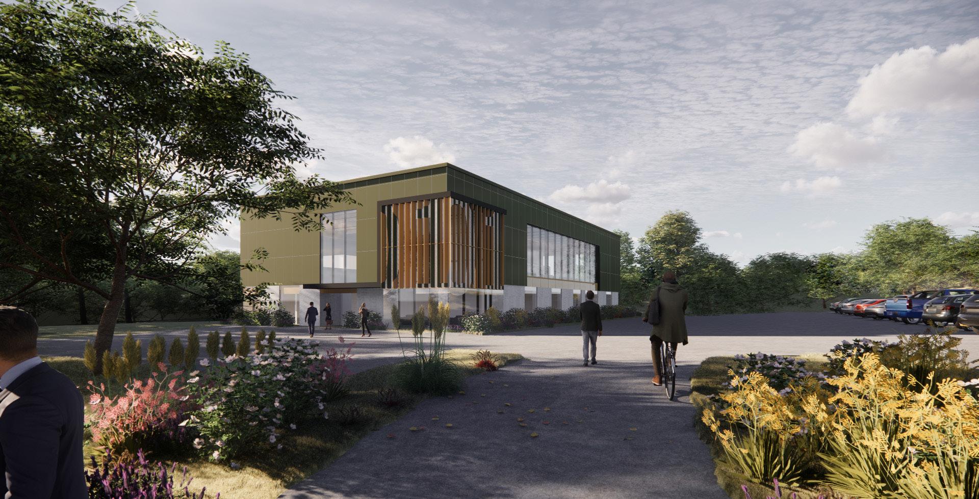
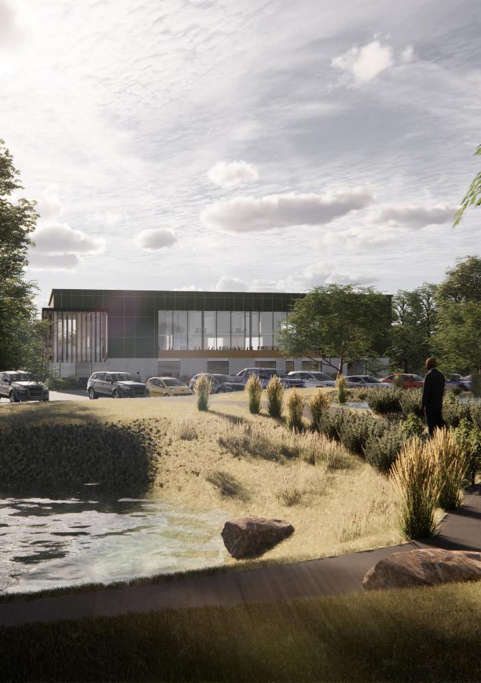
Ickenham Office and Industrial Warehouse Development
Location:
Category:
Client: Project Year:
Ickenham, England Commercial, Industrial Kitewood 2022
Ickenham development is an industrial and commercial project appointed by client Keltbray. The site is located to the north of Ickenham, a residential suburb situated between Uxbridge and Ruislip.
The subject lands have been vacant for 2 years. The existing buildings sit within a convoluted layout that are not only small in size but unsuitable for re-use for a modern employment operator.
The proposal aims to upgrade the spatial quality within the site by providing significant percentage of the landscape area and updating existing buildings. The scheme includes an office block based on existing structure and 4 newly built industrial warehouses.
Work involved:
Concept development
AutoCAD drawings
Visualization (Enscape)
SketchUp modelling
Diagrams drawings
Design code
Design access statement
Planning package
03
|


Food Service Counter up Canteen Meeting room Entrance Kitchen Storage Storage Post Acc WC WC A A Meeting room Meeting room WC WCWC SH Acc WC/SH up Meeting Office Storage Male WC Female WC CC Acc WC Storage Booth Booth Booth Booth A A Issue Date By Chkd Appd Issue Date By Chkd Appd Client Job Title Drawing Title Project Scale Drawing Keltbray 1381 dimensions are approximate, detailed be carried out by Contractor before on building works. All levels and dimensions to be confirmed on site. drawing information is indicative and subject to the detailed site survey. - Drawing for information only. - Do not scale from this drawing. - This drawing is copyrighted. PLANNING 1:100 Proposed Building Floor Plans Former MSD Facility, Breakspear Road South, Ickenham LEVEL LEVEL 1 RJ 00 28/09/22 MMRS Food Service Counter up Canteen Meeting room Entrance Kitchen Storage Storage Post Acc WC WC A A Meeting room Meeting room WC WCWC SH Acc WC/SH up Meeting Office Storage Male WC Female WC CC Acc WC Storage Booth Booth Booth Booth A A LEVEL LEVEL 1 0 24 10M FFL +0.00 Bottom edge Insulated Cladding Panels +2.50 Top Masonry Wall Precast Concrete Cladding +2.69 FFL +3.95 B C F G GL -0.15 RL +8.85 Bottom edge of Insulated Cladding Panels +2.50 Top Masonry Wall Precast Concrete Cladding +2.69 A B F G H Top Masonry Wall Precast Concrete Cladding +4.45 (Where associated with window openings) Window head level +7.50 +3.45 DateByChkdAppdIssueDateByChkdAppd Client Job Title Drawing Title Project No Scale at A0 Issue Drawing Status Keltbray Drawing No 1381 Former MSD Facility, Breakspear Road South, Ickenham campbell architects Safety, Health and Environmental Information General Note normally the types work detailed drawing the Designer Risk Assessments and health and safety plan, note the following:competent Contractor working where appropriate, be an approved method statement. - applicable, significant highlighted in the body the drawing. - levels and dimensions are approximate, detailed site must be carried out by Contractor before commencement building works. All levels and - All existing drawing subject the detailed site survey. - Drawing for information only. - Do not scale from this drawing. - This drawing copyrighted. Stage 3+ 1:50 00 SN 00 06/04/23 RSCC 1381-DR-A-30-105 Building 1: General Arrangement North & South Elevations 01 Proposed GA Elevation: North Scale 1:50 01 Proposed GA Elevation: South Scale 1:50 0 24 10M GL -0.15 Bottom edge Insulated Cladding Panels +2.50 Top Masonry Wall Precast Concrete Cladding +2.69 CL +3.45 PL +9.53 A B G H Top of Masonry Wall Precast Concrete Cladding +4.45 (Where associated with window openings) FFL +3.95 Issue DateByChkdAppdIssueDateByChkdAppd Client Drawing Title Project No Drawing Status Keltbray Drawing No 1381 Former MSD Facility, Breakspear Road South, Ickenham campbell architects Safety, Health and Environmental Information General Note addition the hazards/risks normally associated with the types of work detailed this drawing and noted Designer and safety plan, note the following: - assured that works on this will be carried out by competent Contractor working where appropriate, be an approved method statement. - Where applicable, significant residual risks are highlighted in the body the drawing. - levels and dimensions approximate, detailed surveys by building dimensions confirmed on site. - All existing drawing information is indicative and subject the detailed site survey. - Drawing for information only. - Do not scale from this drawing. - This drawing copyrighted. Stage 3+ 1:50 00 SN 06/04/23 RSCC 1381-DR-A-30-105 Building 1: General Arrangement North & South Elevations 01 Proposed GA Elevation: North Scale 1:50 01 Proposed GA Elevation: South Scale 1:50 +9.53 Top Masonry Wall Precast Concrete Cladding +4.45 (Where associated with window openings) Window head level +7.50 +9.53 Top Masonry Wall Precast Concrete Cladding +2.69 Top Masonry Wall Precast Concrete Cladding +4.45 (Where associated with window openings) FFL +3.95 DateByChkdAppdIssueDateByChkdAppd campbell architects Safety, Health and Environmental Information normally types drawing the Designer Risk Assessments and health and safety plan, note the following: - by competent Contractor working where appropriate, to an approved method statement. - Where applicable, significant residual risks are highlighted the body the drawing. - approximate, site surveys must be carried out Contractor before commencement building works. All levels and - All existing drawing subject to the detailed site survey. - Drawing information only. - Do not scale from this drawing. - This drawing copyrighted. SN 00 06/04/23 RSCC 01 Proposed GA Elevation: East Scale 1:50 02 Proposed GA Elevation: West Scale 1:50 Building Fabric Specification (Refer to detailed manufacturer specification for further information) Element U-Value -Kingspan Quadcore KS1000 RW - 115mm Wall 0.26 -Kingspan Quadcore AWP -KS600-1000MR Wall Panel, Micro-Rib - 74mm -Forticrete Fairfaced Dense Concrete Block 'Flint' (390mm 190mm 90mm) -Insulated Cavity - 50mm Kooltherm K108 insulation -Creagh Pre-cast Concrete Panel - 150mm (Rekli Formliner (Rib Type N)) Wall 3:(Buildings & only) -Reinforced concrete retaining wall - 300mm -Cellecta Hexatherm XPeri (External) - 70mm Ground Floor: 0.18 -RC Concrete Slab - 250mm (with Sikafloor -1 MetalTop, one part, pre-blended metallic dry shake hardener) -Cellecta Hexatherm Xfloor 300 (20mm) insulation -160mm dufaylite clayboard OSA (to S/E specification) Openings: -Norton Industrial Doors Insulated Roller Shutter Door Personnel Doors 1.4 -Strongdor Climador Roof lights -Kingspan Day-Lite Trapezoidal Rooflight (KS1000 DLTR Opal) Curtain Walling 1.6 -Reynaers ConceptWall 50 Curtain Walling system -Reynaers ConceptSystem 77 window system RL +8.85 PL +9.53 1 2 3 4 3805.0 6285.0 2170.0 5 5750.0 GL -0.15 FFL +0.00 RL +8.85 PL +9.53 Bottom edge of Insulated Cladding Panels +2.50 Top of Masonry Wall Precast Concrete Cladding +2.69 Top of Masonry Wall Precast Concrete Cladding +4.45 (Where associated with window openings) Window head level +7.50 FFL +3.95 CL +3.45 1 2 3 4 3805.0 6285.0 2170.0 5 5750.0 01 Proposed GA Elevation: East Scale 1:50 Building Fabric Specification (Refer to detailed manufacturer specification for further information) Element U-Value (W/m2K) Roof: 0.18 -Kingspan Quadcore KS1000 RW - 115mm Wall 1: 0.26 -Kingspan Quadcore AWP -KS600-1000MR Wall Panel, Micro-Rib - 74mm Wall 2: 0.24 -Forticrete Fairfaced Dense Concrete Block 'Flint' (390mm 190mm x 90mm) -Insulated Cavity - 50mm Kooltherm K108 insulation -Creagh Pre-cast Concrete Panel - 150mm (Rekli Formliner (Rib Type N)) Wall 3:(Buildings 3 & 4 only) 0.26 -Reinforced concrete retaining wall - 300mm -Cellecta Hexatherm XPeri (External) - 70mm Ground Floor: 0.18 -RC Concrete Slab - 250mm (with Sikafloor -1 MetalTop, one part, pre-blended metallic dry shake hardener) -Cellecta Hexatherm Xfloor 300 (20mm) insulation -160mm dufaylite clayboard OSA (to S/E specification) Openings: Access Doors 0.69 -Norton Industrial Doors Insulated Roller Shutter Door Personnel Doors 1.4 -Strongdor Climador Roof lights 1.6 -Kingspan Day-Lite Trapezoidal Rooflight (KS1000 DLTR Opal) Curtain Walling 1.6 -Reynaers ConceptWall 50 Curtain Walling system Windows 1.3 -Reynaers ConceptSystem 77 window system GL -0.15 RL +8.85 Bottom edge Insulated Cladding Panels +2.50 Top of Masonry Wall Precast Concrete Cladding +2.69 (Where associated with window openings) Window head level +7.50 +3.45 Bottom edge Insulated Cladding Panels +2.50 Top of Masonry Wall Precast Concrete Cladding +2.69 Top of Masonry Wall Precast Concrete Cladding +4.45 (Where associated with window openings) Issue DateByChkdAppdIssueDateByChkdAppd campbell architects Safety, Health and Environmental Information addition the hazards/risks normally associated with types of work drawing Designer and safety plan, note the following: - is assured that all works on this will be carried out by competent working appropriate, be an approved method statement. - Where applicable, significant residual risks are highlighted the body the drawing. - approximate, surveys by commencement on building works. All levels and dimensions be confirmed on site. - All existing drawing information subject the detailed site survey. - Drawing is for information only. - Do not scale from this drawing. - This drawing copyrighted. SN 06/04/23 RSCC 01 Proposed GA Elevation: East Scale 1:50 02 Proposed GA Elevation: West Scale 1:50-Creagh Pre-cast Concrete Panel - 150mm (Rekli Formliner (Rib Type N)) Wall 3:(Buildings only) 0.26 -Reinforced concrete retaining wall - 300mm -Cellecta Hexatherm XPeri (External) - 70mm Ground Floor: -RC Concrete Slab - 250mm (with Sikafloor MetalTop, one part, pre-blended metallic dry shake hardener) -Cellecta Hexatherm Xfloor 300 (20mm) insulation -160mm dufaylite clayboard OSA (to S/E specification) Openings: Access Doors 0.69 -Norton Industrial Doors Insulated Roller Shutter Door Personnel Doors 1.4 -Strongdor Climador Roof lights 1.6 -Kingspan Day-Lite Trapezoidal Rooflight (KS1000 DLTR Opal) Curtain Walling 1.6 -Reynaers ConceptWall 50 Curtain Walling system Windows 1.3 -Reynaers ConceptSystem window system Elevations / Floor plans / Specifications


HL (+2.287) 00 (+0.00) 01 (+4.575) 300.0 Lowest Point 300.0 1100.0 1200.0 300.0 300.0 2000.0 1300.0 2500.0 1300.0 2500.0 10 11 12 13 14 21 20 19 18 17 16 15 22 23 24 25 26 27 28 A A 3550.0 7740.0 54 32 A A 3550.0 7740.0 not scale Issue DateBy Chkd Appd Issue DateBy Chkd Appd Client Job Title Drawing Title Project No Scale at A0 Issue Drawing Status Keltbray Drawing No 1381 Former MSD Facility, Breakspear Road South, Ickenham campbell architects Safety, Health and Environmental Information General Note addition normally the types of work detailed this drawing and noted in the Designer Risk Assessments and health and safety plan, note the following: - assured that all works on this will be carried out by competent Contractor working where appropriate, to be an approved method statement. - Where applicable, significant residual risks are highlighted in the body of the drawing. - All levels and dimensions are approximate, detailed site surveys must be carried out by Contractor before building dimensions be confirmed on site. - All existing drawing information indicative and subject to the detailed site survey. - Drawing is for information only. - Do not scale from this drawing. - This drawing is copyrighted. Stage 3+ 1:20 00 SN 00 06/04/23 RSCC Notes to Contractor: - Stair balustrade to comply with Approved Document Part K - Final design subject to fire consultant input regarding width of stairs and riser/going - Signage strategy subject to client input 01 B4 Typical Core Section A-A 1:20 03 B4 Typical Stair Core Ground Floor Plan 1:20 02 B4 Typical Stair Core First Floor Plan 1:20 1381-DR-A-24-604 Proposed B4 Stair Core Typical Details Accessible door Accessible door Concrete staircase, to S/E design Stair nosings as per approved docs Half landing support to S/E design & specification Riser: 163.4 mm Going: 280 mm Steel beam behind 2000mm clear head height Stair nosings 2900 FFL +0.05 FFL +2.49 DL +2.25 2377 2900 FFL +0.05 FFL +2.49 DL +2.25 3400 2900 FFL +0.05 FFL +2.49 DL +2.25 2377 1023 882 473 2900 FFL +0.05 FFL +2.49 DL +2.25 3400 C A B D D4 D3 473 1023 882 2377 3400 977 1023 1400 1048 1852 500 1600 777 Do not scale Issue DateBy Chkd Appd Issue DateBy Chkd Appd Client Job Title Drawing Title Project No Scale at A0 Issue Drawing Status Keltbray Drawing No 1381 Former MSD Facility, Breakspear Road South, Ickenham campbell architects Safety, Health and Environmental Information General Note the hazards/risks normally associated with the types work detailed this drawing and noted the Designer Risk Assessments and health and safety plan, note the following: - out by competent Contractor working where appropriate, be an approved method statement. - Where applicable, significant residual risks are highlighted the body of the drawing. - All levels and dimensions are approximate, detailed site surveys must be carried out by Contractor before commencement building works. All levels and dimensions to be confirmed on site. - All existing drawing information is indicative and subject the detailed site survey. - Drawing for information only. - Do not scale from this drawing. - This drawing copyrighted. Stage 3+ 1:20 1:10 00 SN 00 06/04/23 RSCC 1381-DR-A-70-609 Proposed B2 Welfare Facilities DetailsChanging Room 04 Changing Room Elevation C 1:20 02 Changing Room Elevation A 1:20 03 Changing Room Elevation B 1:20 05 Changing Room Elevation D 1:20 05 01 05 07 01 02 03 06 06 07 04 Changing Room Plan 1:10 Key 01 02 03 04 Stud wall Mirror Seating Hand dryer 05 06 07 08 Lockers Basin Sofa D4 01 06 05 07 03 3350 3950 FFL +0.05 CL +2.75 DL +2.25 3950 3810 2550 1880 3350 3810 FFL +0.05 CL +2.75 DL +2.25 3350 3950 FFL +0.05 CL +2.75 DL +2.25 3350 3810 FFL +0.05 CL +2.75 DL +2.25 Do not scale Issue DateBy Chkd Appd Issue DateBy Chkd Appd Client Job Title Drawing Title Project No Scale at A0 Issue Drawing Status Keltbray Drawing No 1381 Former MSD Facility, Breakspear Road South, Ickenham campbell architects Safety, Health and Environmental Information General Note In addition to the hazards/risks normally associated with the types work detailed this drawing and noted the Designer Risk Assessments and health and safety plan, note the following: - assured that all works on this will be carried out by competent Contractor working where appropriate, be an approved method statement. - Where applicable, significant residual risks highlighted the body of the drawing. - All levels and dimensions are approximate, detailed site surveys must be carried out by Contractor before commencement building dimensions to be confirmed on site. - All existing drawing information is indicative and subject the detailed site survey. - Drawing for information only. - Do not scale from this drawing. - This drawing copyrighted. Stage 3+ 1:20 1:10 00 SN 00 06/04/23 RSCC 1381-DR-A-70-606 Key 01 02 03 04 Stud wall Mirror Hand dryer Sink 05 06 07 Accessible Toilet Toilet Doors Toilet Proposed B1 Welfare Facilities Details First Floor Toilet 04 02 03 05 B1 First Floor Typical WC Plan 1:10 B1 First Floor Typical WC Elevation A 1:20 B1 First Floor Typical WC Elevation B 1:20 B1 First Floor Typical WC Elevation C 1:20 B1 First Floor Typical WC Elevation D 1:20 01 01 02 03 04 06 03 04 05 03 07 04 C A B D D1 3395 3623 290 1450 300 1023 560 1135 1200 1065 2900 FFL +0.05 FFL +2.49 DL +2.25 3400 2900 FFL +0.05 FFL +2.49 DL +2.25 3623 2900 1450 750 1065 FFL +0.05 FFL +2.49 DL +2.25 1200 1135 3400 2900 FFL +0.05 FFL +2.49 DL +2.25 3623 1450 750 not scale Issue DateBy Chkd Appd Issue DateBy Chkd Appd Client Job Title Drawing Title Project No Scale at A0 Issue Drawing Status Keltbray Drawing No 1381 Former MSD Facility, Breakspear Road South, Ickenham campbell architects Safety, Health and Environmental Information General Note addition to the hazards/risks normally the types of work detailed this drawing and noted the Designer Risk Assessments and health and safety plan, note the following: - assured that all works on this will be carried out by competent Contractor working where appropriate, to be an approved method statement. - Where applicable, significant residual risks are highlighted in the body of the drawing. - All levels and dimensions are approximate, detailed site surveys must be carried out by Contractor before building dimensions be confirmed on site. - All existing drawing information indicative and subject to the detailed site survey. - Drawing is for information only. - Do not scale from this drawing. - This drawing is copyrighted. Stage 3+ 1:20 1:10 00 SN 00 06/04/23 RSCC 1381-DR-A-70-623 Proposed B5 Welfare Facilities DetailsOffice Officee Plan 1:10 Key 12 13 14 Book shelves Storage Office chair & desk 04 02 Office Elevation A 1:20 03 Office Elevation B 1:20 05 Office Elevation C 1:20 Office Elevation D 1:20 13 12 14 15 01 12 13 14 Detail arrangement
03 | PART 2 PROFESSIONAL WORKS
Listed Building Restoration and Mixed-use Development
Location:
Category:
Client:
Project Year:
London, England Restoration, Mixed-use Kitewood 2022

Background and Site
London 446 Fulham Road Development is a design competition based on the site which comprises the existing listed building Sir Oswald Stoll Mansions used as services veterans, the charities administration facilities, NHS medical centre and various ancillary communal facilities for use by the charity. The site is 0.71 Hectares and includes a total of 137 residential units.
The flats and facilities are considered obsolete and not ‘fit for purpose’ with a key objective of the new scheme to deliver efficient new space as demonstrated within our proposal.
A further 20 Veterans apartments are located in Bush House, located on the sites access road, adjacent and to the west, outside of the site boundary.
Design Proposal
Our proposals seek to intensify the existing use of ‘previously developed land’ and under-used buildings to deliver high quality homes and supporting accommodation. An increased footprint is supported as a starting point by the council, who wish to resist the net loss of permanent residential accommodation as a result of new redevelopment.
Work involved:
Concept development
AutoCAD drawings
SketchUp modelling Visualization (Photoshop)
Diagrams drawings Competition package preparation
DESIGN METHODOLOGY
High quality design utilising suitable materials such as brick and stone to offer a natural transition with the Grade II listed Mansion building on Fulham Road.
‘Stepped’ building heights away from Fulham Road of suitable building height, with full consideration of the surrounding environment and townscape.
Suitable building relationships considered in the context of outlook, relationship with the surrounding urban grain and to offer appropriate ‘Sunlight and daylight’ reflecting initial due diligence.
Introduction of permeability with a large central garden to form a key feature of the site. The move away from linear building forms offers multiple views into the central amenity spaces, for the enjoyment of tenants and the local community.


Promote a high quality scheme that reflects its central and sustainable urban location which provides a depth of amenities and good transport infrastructure reflected by PTAL rating, 5/6a alongside its well recognised address.

Communal space view
space view
centre and formal garden view
garden view
Communal
Medical
Formal
03 | PART 2 PROFESSIONAL WORKS
45 Old Quay Road House
Location:
Category:
Client:
Project Year:
Holywood, Northern Ireland
Residential Private 2023
This project is a modern private house situated in Holywood, Northern Ireland, designed to sit on sloping topography. The house is a two-storey building with a total Gross Internal Area (GIA) of 300 square meters. The design of the house includes an open plan living room and kitchen on the upper floor, with large glazing that provides magnificent views of Belfast loch.
The upper floor also features a balcony that runs across the living room and TV room, creating an outdoor dining and leisure space. The main entrance to the house is on the upper floor, while the lower floor comprises three bedrooms and a potential fourth bedroom. The circulation core of the house is located in the centre, allowing easy movement between the different areas.
The house’s design is focused on creating a comfortable and modern living space that maximizes the benefits of its location. The large glazing of the living room and TV room introduces plenty of natural light and allows for an unobstructed view of the surroundings. The balcony provides a perfect place for outdoor entertainment and relaxation.
Work involved:
Concept development Revit / AutoCAD drawings
3D modelling
Visualization (Vray)
Diagrams drawings Planning application package


UP UP TV Fireplace 0123 45m Issue DateByChkdAppdIssueDateByChkdAppd Client Job Title Drawing Title Project No Scale at A3 Issue Drawing Status Drawing No www.campbellarchitects.co.uk campbellarchitects Safety, Health and Environmental Information General Note In addition to the hazards/risks normally associated with the types of work detailed on this drawing and noted in the Designer safety plan, note the following:It is assured that all works on this will be carried out by a competent Contractor working where appropriate, to approved method statement.Where applicable, significant residual risks are highlighted in the body of the drawing.approximate, surveys must be carried out by Contractor before commencement on building works. All levels and dimensions to be confirmed on site.All existing drawing information is indicative and subject to the detailed site survey.Drawing is for information only.Do not scale from this drawing.This drawing is copyrighted. XX 00 00/00/00 XXXX Campbell Architects 1335 Old Quay Road PLANNING 1:100 1335-DR-A-00-000 Proposed First Floor Plan 00 UP WR WR UP WR 0123 45m Do not scale Issue DateByChkdAppdIssueDateByChkdAppd Client Job Title Drawing Title www.campbellarchitects.co.uk campbellarchitects Safety, Health and Environmental Information General Note normally associated the types of work detailed on this drawing and noted in the Designer safety plan, note the following:It is assured that all works on this will be carried out by a competent Contractor working where appropriate, to be an approved method statement.Where applicable, significant residual risks are highlighted in the body of the drawing.All levels and dimensions are approximate, detailed site surveys must be carried out by Contractor before commencement on building works. All levels and dimensions to be confirmed on site.All existing drawing information is indicative and subject to the detailed site survey.Drawing is for information only.Do not scale from this drawing.This drawing is copyrighted. XX 00 00/00/00 XXXX Campbell Architects Old Quay Road Proposed Ground Upper floor plan Lower floor plan Visualisation (Vray)
2 TECHNICAL WORKS
Restoration of a residential house
Location:
Category:
Client:
Project Year:
Cultra , Northern Ireland
Residential Private 2023
Trory Lodge is a private residential restoration project in Cultra area, Northern Ireland. The clients aim to restore their vacant old house which was designed and built in 1948. The proposal is to maximise the existing structure for minimising the budget while upgrade the spatial quality of dwelling. Therefore, the design team focused on the rearrangement of the window opening and internal space arrangement. Demolition plan and detailed construction drawings have been provided.
-
-
04
| PART
873 2135 W-01 W-02 EXD-01 W-05 EXD-02 1897 1245 2135 2478 2135 2478 2135 1866 2135 3523 2040 906 1533 1245 1245 * * * * * * * **** **** Δ Emergency Egress Window (see note) W-15 1245 890 2135 2478 * W-13 1559 576 2135 1263 * 2135 1500 W-12 1559 576 2135 1263 * W-10 1559 505 2064 3348 * W-08 1050 1050 2100 1800 FFL * ** * * * * *See note re. Safety Glazing EXD-05 **** **** **** **** Work involved: Technical drawings FFL * EXD-01 W-05 EXD-02 EXD-03 W-06 2478 890 2135 1866 2135 3523 2040 906 890 2135 1866 1245 1533 602 1245 *** **** * * * * * * * * * * * * * external steps 2 no. risers, 280mm going, 125mm rise external steps 2 no. risers, 280mm going, 125mm rise external steps 2 no. risers, 280mm going, 125mm rise 2878 *** * *** * *** * Δ Emergency Egress Window (see note) Δ Emergency Egress Window (see note) 890 890 576 576 505 FFL **** Do not scale Issue DateByChkdAppdIssueDateByChkdAppdClient 55 Whitfield Street, London W1T 4AH www.campbellarchitects.co.uk campbellarchitects Safety, Health and Environmental Information General Note In addition to the hazards/risks normally associated with the types of work detailed on this drawing and noted in the Designer Risk Assessments and health and safety plan, note the following:
It is assured that all works on this will be carried out by a competent Contractor working where appropriate, to be an approved method statement.
Where applicable,
residual risks are
significant
highlighted in the body of the drawing.
levels and dimensions are approximate, detailed
levels
confirmed
site.
- All
site surveys must be carried out by Contractor before commencement on building works. All
and dimensions to be
on
existing drawing information is indicative and
site
- All
subject to the detailed
survey.
- Drawing is for information only.
- Do not scale from this drawing.
NJ 00 27/01/23 RSCC 01 Proposed South Elevation 02 Proposed North Elevation
- This drawing is copyrighted.


Emergency Egress Window (see note) W-01 See note re. Safety Glazing EXD-03 1897 2478 2478 890 1866 3523 906 1866 * external steps no. risers, 280mm going, 125mm rise external steps no. risers, 280mm going, 125mm rise external steps no. risers, 280mm going, 125mm rise **** Emergency Egress Window (see note) Emergency Egress Window (see note) W-16 2478 2478 W-13 1559 576 1263 1500 1263 3348 FFL FFL *See note re. Safety Glazing Issue DateByChkdAppdIssueDateByChkdAppdClient Job Title Drawing Title Project No Scale at A1 Issue Drawing Status Mr & Mrs Prosser Drawing No 1390 13 Clanbrassil Road, Cultra 55 Whitfield Street, London W1T 4AH www.campbellarchitects.co.uk campbellarchitects Safety, Health and Environmental Information General Note addition the hazards/risks normally associated with the types of work detailed on this drawing and noted in the Designer Risk Assessments and health and safety plan, note the following: - assured that all works on this will be carried out by competent Contractor working where appropriate, to be an approved method statement. - Where applicable, significant residual risks are highlighted in the body the drawing. - All levels and dimensions are approximate, detailed site surveys be carried out by before commencement building works. All levels and dimensions to be confirmed on site. - All existing drawing information indicative and subject the detailed site survey. - Drawing for information only. - Do not scale from this drawing. - This drawing copyrighted. 1:50 00 NJ 00 27/01/23 RSCC Proposed South & North Elevations Construction 1390-DR-A-50-100 01 Proposed South Elevation 02 Proposed North Elevation W-09 1263 W-07 1866 *See note re. Safety Glazing Emergency Egress Window (see note) *See note re. Safety Glazing W-04 Existing window opening blocked up and finishes made good Existing door opening be partially blocked up and all finishes made good Do not scale Issue DateByChkdAppdIssueDateByChkdAppdClient Job Title Drawing Title Project No Scale at A1 Issue Drawing Status Mr & Mrs Prosser Drawing No 1390 13 Clanbrassil Road, Cultra 55 Whitfield Street, London W1T 4AH www.campbellarchitects.co.uk campbellarchitects Safety, Health and Environmental Information General Note addition normally the types of work detailed this drawing and noted in the Designer Risk Assessments and health and safety plan, note the following: - assured that all works this will be carried out by competent Contractor working where appropriate, to be an approved method statement. - Where applicable, significant residual risks highlighted in the body the drawing. - All levels and dimensions are approximate, detailed site surveys must be carried out by Contractor before commencement building works. All levels and dimensions to be confirmed on site. - All existing drawing information indicative and subject the detailed site survey. - Drawing for information only. - Do not scale from this drawing. - This drawing copyrighted. 1:50 00 NJ 00 27/01/23 RSCC Proposed West East Elevations Construction 1390-DR-A-50-101 03 Proposed West Elevation 04 Proposed East Elevation Ensuite 2 Bedroom Bedroom Ensuite 3 Bedroom Hall Porch Garage Boiler House Existing 600mm Existing Wavin Existing 600mm Existing Wavin Existing 600mm Existing 600mm Existing 600mm Existing Wavin Existing Existing BIGT Gully Existing BIGT Gully Existing BIGT Gully Existing BIGT Gully Existing Gully TD WM Monoxide CM Heat HD 3616 W-01 W-05 W-08 W-10 EXD-05 W-13 W-15 W-16 W-03 D-01 positioned 1000mm 3000mm away from the boiler ensure that point the away from detector. Heat detector located to ensure that no point the room is more than 5300mm away from Kitchen Utility Living Room Lounge Study Smoke Detector Smoke Detector A A D-03 D-04 Existing Gully Existing Gully Existing BIGT Gully Existing BIGT Gully Existing BIGT Gully Existing SVP Existing Gully WC Ensuite 1 8200 Issue DateByChkdAppdIssueDateByChkdAppdClient Job Title Drawing Title Project No Scale at A1 Issue Drawing Status Mr & Mrs Prosser Drawing No 1390 13 Clanbrassil Road, Cultra www.campbellarchitects.co.uk campbellarchitects Safety, Health and Environmental Information General Note In addition the hazards/risks normally associated with the types work detailed on this drawing and noted in the Designer Risk Assessments and health and safety plan, note the following: - be carried out competent Contractor working where appropriate, to be an approved method statement. - Where applicable, significant residual risks are highlighted the body of the drawing. - All levels and dimensions are approximate, detailed site surveys must be carried out by Contractor before commencement on building works. All levels and dimensions to be confirmed on site. - All existing drawing information indicative and subject the detailed site survey. - Drawing for information only. - Do not scale from this drawing. - This drawing is copyrighted. 1:50 00 Proposed Floor Plan Construction 1390-DR-A-30-101 KEY Existing fabric Proposed areas to be altered DXXX DXXX DXXX DXXX 01 Proposed Floor Plan 1981 830 Existing Wavin WM Smoke Detector 1203 600 1580 W-08 D-03 1800 600 Existing Gully Existing BIGT Gully A A 2100 1800 KEY A Existing Fabric not scale Issue DateByChkdAppdIssueDateByChkdAppdClient Job Title Drawing Title Project No Scale A1 Issue Drawing Status Mr & Mrs Prosser Drawing No 1390 13 Clanbrassil Road, Cultra 55 Whitfield Street, London W1T 4AH www.campbellarchitects.co.uk campbellarchitects Safety, Health and Environmental Information General Note In addition to the hazards/risks normally associated with the types of work detailed on this drawing and noted the Designer Risk Assessments and health and safety plan, note the following: - assured that all works on this will be carried out by competent Contractor working where appropriate, be an approved method statement. - Where applicable, significant residual risks are highlighted in the body the drawing. - All levels and dimensions are approximate, detailed site surveys must be carried out by Contractor before commencement building works. All levels and dimensions be confirmed on site. - All existing drawing information indicative and subject to the detailed site survey. - Drawing is for information only. - Do not scale from this drawing. - This drawing copyrighted. 1:20/1:50 00 NJ 00 27/01/23 RSCC Utility Room Construction Detail A Construction 1390-DR-A-110-100 01 Section A-A 1:20 Construction detail through utility room 02 Elevation A 1:50 South elevation of proposed utility room and window 03 Plan A 1:50 Construction detail through utility room A Elevations Floor plans / Technical details
Apartment block refurbishment project in Harrow
04 | PART 2 TECHNICAL
Location: Category: Client: Project Year: Kenton Road, Harrow, England Residential Strawberry Star 2022
WORKS
01 Typical Envelope Bay Study 01 Section A-A 02 DET A-A DET A-A Existing brickwork onto existing concrete frame Existing brickwork be repointed where required subject to scope agreement Existing brickwork to have colour tint treatment colour to be agreed Contractor to allow full brick reveal requirement for metal window reveal surround to be reviewed on site See window package for details Windows to existing brickwork areas will be fitted within existing openings. Openings to be primed and made good. Contractor to allow for EPDM to all sides and sealant as per the manufacturer's details New insulated brick slip system fixed to 12mm sheathing board onto new metsec (assume 100mm insulated stud) Allow for full brick reveal in new brick slip extent See window package for details Contractor to allow for EPDM works, cavity stops and cavity trays to all windows where required Contractor to allow for metal trim with cavity tray behind at junction between new brick slip system and existing brick facade New insulated brick slip system fixed to 12mm sheathing board onto new metsec (assume 100mm insulated stud) See metalwork package for steel balustrade details. Metal capping profile to top of parapet on metsec with cavity stop Insulated aluminium cladding system fixed back to sheathing board to new steel frame structure Aluminium reveal as part of cladding system Contractor to allow for metal trim with cavity tray behind at junction between new brick slip system and existing brick facade Existing brickwork be repointed where required subject to scope agreement Existing brickwork to have colour tint treatment colour to be agreed Refer to Drawing 36-700 Detail 1 Refer to Drawing 36-700 Detail 5 Refer to Drawing 36-700 Detail 4 Refer to Drawing 36-700 Detail 3 Issue DateByChkdAppdIssueDateByChkdAppdClient Job Title Scale at A1 Issue Drawing Status Strawberry Star campbellarchitects Safety, Health and Environmental Information General Note In addition to the hazards/risks normally associated with the types of work detailed on this drawing and noted in the Designer Risk Assessments and health and safety plan, note the following: - All levels and dimensions are approximate, detailed site surveys must be carried out by Contractor before commencement on building works. All levels and dimensions to be confirmed on site. - All existing drawing informtion is indicative and subject to the Stage 3+ NOT FOR CONSTRUCTION Notes to Contractor: - Drawing to be read in conjunction with window package and envelope scope drawings - Contractor to allow for none combustible brick slip system - Contractor to allow for all required accessories ie cavity trays, sheething board where required, weep holes etc. - Contractor to allow for movement joints as per manufacturer's recommendations - All envelope details yet to be coordinated with structural design - All fire stopping as per the fire strategy package Location Diagram SN 00 29/07/22 MMRS 02 Existing brickwork onto existing concrete frame Existing brickwork be repointed where required subject to scope agreement Existing brickwork to have colour tint treatment colour to be agreed Contractor to allow full brick reveal requirement for metal window reveal surround to be reviewed on site See window package for details Windows to existing brickwork areas will be fitted within existing openings. Openings to be primed and made good. Contractor to allow for EPDM to all sides and sealant as per the manufacturer's details existing brick facade Do not scale 55 Whitfield Street, London W1T 4AH www.campbellarchitects.co.uk campbellarchitects Safety, Health and Environmental In addition to the hazards/risks normally work detailed on this drawing and Assessments and health and safety - is assured that all works on this Contractor working where appropriate, statement. - Where applicable, significant residual body of the drawing. Location Diagram Work involved: Technical drawings
01 CT 01 TYPICAL APARTMENT INSULATED MF CEILING ON EXISTING SLAB Specification ref: K10 11 TBC 02 CT 02 TYPICAL APARTMENT INSULATED MF BATHROOM CEILING ON EXISTING SLAB Specification ref: K10 11 TBC 03 04 CT 03 TYPICAL APARTMENT MF CEILING ON NEW FLOOR STRUCTURE CT 04 TYPICAL APARTMENT MF BATHROOM CEILING ON NEW FLOOR STRUCTURE FCL USL USL FCL USL FCL USL FCL 05 FCL USL CT 05 TYPICAL CORRIDOR ACCESSIBLE CEILING TYPE TBC Specification ref: K10 11 TBC Existing concrete slab Gypframe soffit cleat fixed to hanger Gypframe strap hanger Gypframe MF6 ceiling perimeter channel fixed to wall 600mm centres Gypframe MF7 primary support channel 12.5mm Gyproc, taped and jointed with painted finish Gypframe MF5 ceiling section 450mm centres 50mm Isover Spacesaver Ready-Cut insulation in the cavity Gypframe MF5 ceiling section at 450mm centres Existing concrete slab Gypframe soffit cleat fixed hanger Gypframe strap hanger Gypframe MF7 primary support channel 100mm Isover Spacesaver Ready-Cut insulation the cavity 12.5mm Gyproc MR, taped and jointed with painted finish Gypframe MF5 ceiling section at 450mm centres Gypframe soffit cleat fixed hanger Gypframe strap hanger Gypframe MF7 primary support channel 12.5mm Gyproc suspended, taped and jointed with selected finish Gypframe soffit cleat fixed to hanger Gypframe strap hanger Gypframe MF7 primary support channel 12.5mm Gyproc suspended MR, taped and jointed with painted finish Gypframe MF6 ceiling perimeter channel fixed Gypframe MF5 ceiling section at 450mm centres Gypframe MF6 ceiling perimeter channel fixed to wall 600mm centres Gypframe MF6 ceiling perimeter channel fixed wall 600mm centres Gypframe MF5 ceiling section 450mm centres Existing concrete slab Gypframe soffit cleat fixed to hanger Gypframe strap hanger Gypframe MF7 primary support channel Gypframe MF6 ceiling perimeter channel fixed to wall at 600mm centres Suspended ceiling tile 2x15mm Soundbloc on resilient bars fixed timber floor joists Acoustic batts between joists 2x15mm Soundbloc on resistant bars fixed to timber floor joists Acoustic batts between joists Steel and timber floor build uprefer to structural engineer Steel and timber floor build uprefer to structural engineer Potential drop down boxing for image VR inlet and outlet duct be brought to floor level not scale Issue DateByChkdAppdIssueDateByChkdAppdClient Job Title Drawing Title Project No Scale at A1 Revision Drawing Status Strawberry Star 1375 Stage 3+ Kenton Road, Harrow Whitfield Street, London W1T www.campbellarchitects.co.uk campbellarchitects Safety, Health and Environmental Information General Note addition the hazards/risks normally associated with the types of work detailed on this drawing and noted in the Designer Risk Assessments and health and safety plan, note the following: - assured that all works on this will be carried out by a competent Contractor working where appropriate, to be an approved method statement. - Where applicable, significant residual risks are highlighted the body of the drawing. - All levels and dimensions are approximate, detailed site surveys must be carried out by Contractor before commencement on building works. levels and dimensions be confirmed on site. - All existing drawing information indicative and subject to the detailed site survey. - Drawing information only. - Do not scale from this drawing. - This drawing copyrighted. Proposed Internal ceiling detail types XX-DR-A-35-701 Project number 1375 CH 00 27/05/22 CC RS GM 00 29/07/22 CC RS Drawing No 1:2 00 01 CT 01 TYPICAL APARTMENT INSULATED MF CEILING ON EXISTING SLAB Specification ref: K10 11 TBC 02 CT 02 TYPICAL APARTMENT MF BATHROOM CEILING ON EXISTING SLAB Specification ref: K10 11 TBC 03 04 CT 03 TYPICAL APARTMENT MF CEILING ON NEW FLOOR STRUCTURE CT 04 TYPICAL APARTMENT MF BATHROOM CEILING ON NEW FLOOR STRUCTURE FCL USL USL FCL USL FCL USL FCL 05 FCL USL CT 05 TYPICAL CORRIDOR ACCESSIBLE CEILING TYPE TBC Specification ref: K10 11 TBC Existing concrete slab Gypframe soffit cleat fixed hanger Gypframe strap hanger Gypframe MF6 ceiling perimeter channel fixed to wall 600mm centres Gypframe MF7 primary support channel 12.5mm Gyproc, taped and jointed with painted finish Gypframe MF5 ceiling section at 450mm centres 50mm Isover Spacesaver Ready-Cut insulation the cavity Gypframe MF5 ceiling section at 450mm centres Existing concrete slab Gypframe soffit cleat fixed hanger Gypframe strap hanger Gypframe MF7 primary support channel 100mm Isover Spacesaver Ready-Cut insulation the cavity 12.5mm Gyproc MR, taped and jointed with painted finish Gypframe MF5 ceiling section 450mm centres Gypframe soffit cleat fixed hanger Gypframe strap hanger Gypframe MF7 primary support channel 12.5mm Gyproc suspended, taped and jointed with selected finish Gypframe soffit cleat fixed to hanger Gypframe strap hanger Gypframe MF7 primary support channel 12.5mm Gyproc suspended MR, taped and jointed with painted finish Gypframe MF6 ceiling perimeter channel fixed Gypframe MF5 ceiling section 450mm centres Gypframe MF6 ceiling perimeter channel fixed wall 600mm centres Gypframe MF6 ceiling perimeter channel fixed wall 600mm centres Gypframe MF5 ceiling section at 450mm centres Existing concrete slab Gypframe soffit cleat fixed hanger Gypframe strap hanger Gypframe MF7 primary support channel Gypframe MF6 ceiling perimeter channel fixed to wall 600mm centres Suspended ceiling tile 2x15mm Soundbloc on resilient bars fixed timber floor joists Acoustic batts between joists 2x15mm Soundbloc on resistant bars fixed to timber floor joists Acoustic batts between joists Steel and timber floor build uprefer structural engineer Steel and timber floor build uprefer to structural engineer Potential drop down boxing for image VR inlet and outlet duct to be brought floor level Do scale Issue DateByChkdAppdIssueDateByChkdAppdClient Job Title Drawing Title Project No Scale at A1 Revision Drawing Status Strawberry Star 1375 Stage 3+ Kenton Road, Harrow Whitfield Street, London W1T 4AH www.campbellarchitects.co.uk campbellarchitects Safety, Health and Environmental Information General Note addition the hazards/risks normally associated the types work detailed on this drawing and noted the Designer Risk Assessments and health and safety plan, note the following: - assured that works on this will be carried out a competent Contractor working where appropriate, to be an approved method statement. - Where applicable, significant residual risks are highlighted the body the drawing. - All levels and dimensions are approximate, detailed site surveys must carried out by Contractor before commencement on building works. All levels and dimensions to be confirmed on site. - All existing drawing information indicative and subject the detailed site survey. - Drawing for information only. - Do not scale from this drawing. - This drawing copyrighted. Proposed Internal ceiling detail types XX-DR-A-35-701 Project number 1375 CH 00 27/05/22 CC RS GM 00 29/07/22 CC RS Drawing No 1:2 00 01 (+3.497) 02 (+6.850) 03 (+10.520) 04 (+13.755) ROOF (+17.265) 00 (+0.00) HL (+1.752) HL (+5.258) HL (+8.608) HL (+11.930) HL (+15.495) New core walls be lined with painted plasterboard and super graphic signage New steel & timber stair core be lined with plasterboard Existing concrete stair to be made good and finish with clear seal Existing concrete walls to be made good and finished with clear seal and super graphic signage New lift car New steel & timber stair core be lined with plasterboard New concrete core - concrete finish exposed stair lobby New ensitue concrete shaft Allow for over run and lifting beam Existing slab with new structural build up over - refer Structural engineer. Location of corridor door shown (behind) Location of dry riser Allow for new painted steel balustrade with PVC handrail capping to all stair flights New steel stair structure from level 03 upwards to structural engineer's details New lift shaft. Subject to SE and M&E engineer input Existing concrete walls to be finished with clear seal and super graphic signage New steel stair be lined with plasterboard New floor structure over existing slab (L3) refer engineer's details Existing balustrade retained, height to be confirmed SEC A-A Existing and new stair treads to have anti slip edge nosing strips DRY RISER NEW LIFT (min 1700x1750 shaft) Core 1 Additional steps to level only shown dotted handrail to suit New ensitu concrete lift shaft formed to host evacuation lift Refer SE for detail Existing concrete stair core and stair retained made good. Stair core extended with Steel & timber construction to Level 3, L4 Roof. Refer SE for detail. New lift shaft. Subject SE and M&E engineer input Location Diagram Issue DateByChkdAppdIssueDateByChkdAppdClient Job Title Drawing Title Project No Scale at A1 Issue Drawing Status Strawberry Star Drawing No 1375 Kenton Road, Harrow Whitfield Street, London W1T 4AH www.campbellarchitects.co.uk campbellarchitects Safety, Health and Environmental Information General Note addition the hazards/risks normally associated with the types of work detailed on this drawing and noted the Designer Risk Assessments and health and safety plan, note the following: - assured that works on this will be carried out a competent Contractor working where appropriate, approved method statement. - Where applicable, significant residual risks are highlighted the body the drawing. - All levels and dimensions are approximate, detailed site surveys must carried out by Contractor before commencement on building works. All levels and dimensions confirmed on site. - All existing drawing informtion indicative and subject to the detailed site survey. - Drawing for information only. - Do not scale from this drawing. - This drawing copyrighted. 00 STAGE 3+ XX-DR-A-24-601 MM 00 29/07/22 RSCC Proposed Stair Core 01 Typical Details 1:20 50 Notes to Contractor: - Stair balustrade comply with Approved Document Part K - Final design subject to fire consultant input regarding width stairs and riser/going - Stair core venting to be agreed with fire consultant and M&E consultant - New structure to levels 03-05 require structural input - Lift shaft and car indicative only and require M&E and lift specialist input - Signage strategy subject client input 01 02 03 Typical Core Plan (Level 03) 1:20 Typical Core Section A-A 1:50 Typical Core Section Detail 1:20 NOT FOR CONSTRUCTION DET B-B DET A-A DET B-B DET A-A 01 Typical Envelope Bay Study 01 02 Section B-B Section A-A 03 Existing brickwork to be repointed where required subject scope agreement Existing brickwork to have colour tint treatment colour be agreed Existing brickwork to be repointed where required subject scope agreement Existing brickwork to colour be agreed Existing brickwork to be repointed where required subject scope agreement Existing brickwork to have colour tint treatment colour be agreed Existing DPC be reviewed injected DPC required See window package for details Windows to existing brickwork areas will be fitted within existing openings. Openings to be primed and made good. Contractor allow for EPDM to all sides and sealant as per the manufacturer's Contractor to allow for supplier See metalwork package for steel balustrade allow for side fixing through brick slip system and weathering as required See window package Contractor to allow for EPDM works, cavity stops and cavity trays all windows where required Brick slip reveals to head and jamb reveals New insulated brick slip system fixed 12mm sheathing board onto existing concrete frame/new metsec where required Existing brickwork be repointed where required subject to scope agreement Existing brickwork have colour tint treatment colour to be agreed Existing DPC be reviewed injected DPC required Entrance surround to be formed aluminium profile and cladding by specialist onto steel back existing concrete frame as per structural engineer's details Existing brickwork existing concrete frame Entrance surround be formed of aluminium profile and cladding by specialist onto steel sub-frame and fixed back to existing concrete frame as per structural engineer's details Refer Drawing 36-700 Detail Issue DateByChkdAppdIssueDateByChkdAppdClient Job Title Drawing Title Project No Scale at A1 Issue Drawing Status Strawberry Star Drawing No 1375 Kenton Road, Harrow Whitfield Street, London W1T 4AH www.campbellarchitects.co.uk campbellarchitects Safety, Health and Environmental Information General Note addition to the hazards/risks normally associated with the types work detailed on this drawing and noted the Designer Risk Assessments and health and safety plan, note the following: - assured that all works on this will carried out by a competent Contractor working where appropriate, be an approved method statement. - Where applicable, significant residual risks are highlighted the body the drawing. - All levels and dimensions are approximate, detailed site surveys must carried out by Contractor before commencement building works. All levels and dimensions confirmed site. - All existing drawing informtion indicative and subject the detailed site survey. - Drawing for information only. - Do not scale from this drawing. - This drawing copyrighted. Stage 3+ XX-DR-A-36-603 1:20 00 Proposed Envelope Detailed Elevations Sheet 03 NOT FOR CONSTRUCTION Notes to Contractor: - Drawing to be read in conjunction with window package and envelope scope drawings - Contractor to allow for none combustible brick slip system - Contractor to allow for all required accessories ie cavity trays, sheething board where required, weep holes etc. - Contractor to allow for movement joints as per manufacturer's recommendations - All envelope details yet to be coordinated with structural design - All fire stopping as per the fire strategy package Location Diagram 00 Internal ceiling tylical details Envelop detailed elevation Metal work typical details Stair core typical details
MODEL MAKING
Model making is an important method of architectural thinking. Thinking through making is a process in which making and thinking alternate back and forth all the time, in rapid iterations. The making or designing could be taking place intuitively. Reflecting on what has been made helps create knowledge and insights. Creation and reflection go hand in hand – the relationship between the making and the thinking opens up an opportunity to also express knowledge through what is made.
VISUALISATION
Visualisation is a key component of effective communication in architecture. By using 3D modelling software, architects can create visual representations of their designs, helping clients to better understand and visualize the final product. This promotes better communication between architects and clients, resulting in more successful projects.


05 | OTHER WORKS
Model making | Visualisation | Photography
PHOTOGRAPHY
Photography has become an exciting hobby of mine since I started to study architecture. Combining travel and photography has particularly allowed me to appreciate culture from further afield. Looking at architecture through a lens enables you analyse critical principles of form, space, light and shadow to greater details. Photography is also a great way to document my life through visual diary.