Innovative specialists in manufacture of microwave cable & cable assemblies

www.insulatedwire.com

Founded in 1970, IW developed a unique PTFE lamination process and applied it to manufacturing wire and cable. This process allowed IW to manufacture products of unprecedented reliability along with smaller diameters. Combining the new lamination process along with a patented shield design allowed IW to become one of the leaders in low loss microwave transmission lines, utilizing both solid and expanded PTFE dielectrics. In 1988, IW expanded its operations and created a Microwave Products Division.
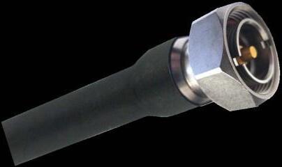
Today, IW Bayport designs and manufactures a wide range of cables to support demanding customer application speci昀椀c requirements for high performance cable assemblies operating at frequencies up to 110GHz, across a range of diameters from 0.034" to 0.750" diameter. IW also offers a broad selection of connectors in order to provide our customers the proper cable assembly for speci昀椀c applications.
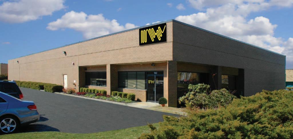
IW operates in two facilities. Headquarters and cable manufacturing are located in Bayport, NY, with the cable assembly facility located close by in Ronkonkoma, NY. Both factories are AS9100 and ISO9001.
Our unique lamination process for EPTFE to create extremely low loss/phase stable cable also provides coax that is capable of high levels of RF power handling.
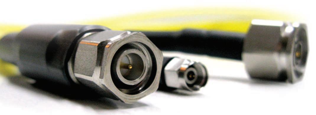
Four main products provide solutions for high RF signal transmission, with a wide range of industry standard interconnect options to ensure reliability in laboratory and harsh environments. IW high power cables are supplied to customers worldwide for use in commercial and military applications where repeatable performance is paramount.
2801: broadband performance to Ku-band, with 450W power handling capability at 18 GHz
4806: rated to 3kW at 1 GHz, operates to X-band
7506SP: 昀氀exible ¾” diameter cable, extremely high power and ease of handling, applications to 6.5 GHz
RF250: RG401 line size hand formable/double shielded cable, eliminates the need for pre-formed semi-rigid cable
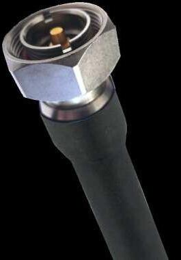
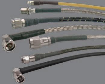
Connector types include N, C, SC, 7/16 DIN, LC, 1 5/8 EIA and 3 1/8 EIA 昀氀ange, different styles are available.
Armoring options and alternate jacket materials are also available, please consult the factory with requirements.

INSULATED WIRE INCORPORATED
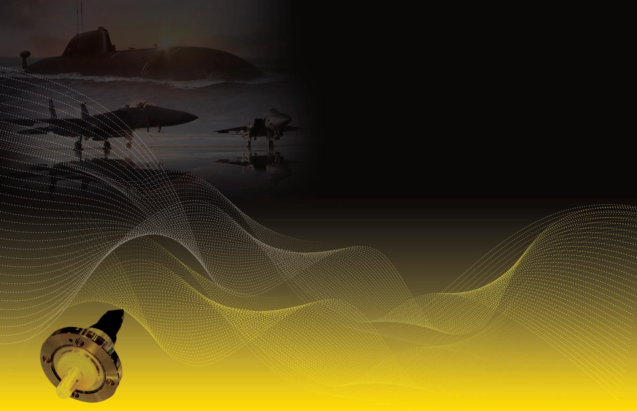
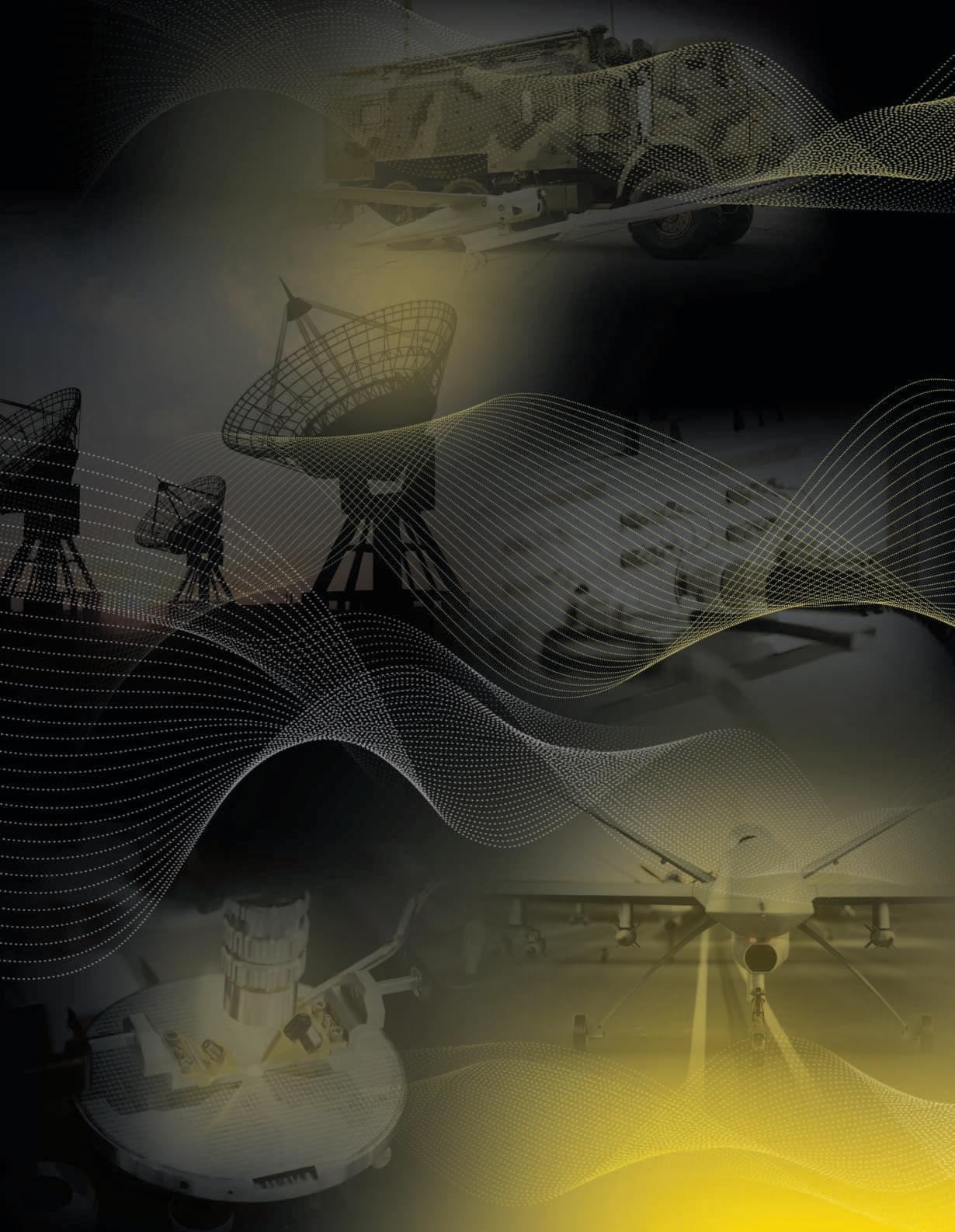
IW serves a broad range of both military and commercial markets. These include telecommunications, data links, satellite systems, airborne electronic warfare and counter measures, missile systems, UAV applications, avionics and instrumentation, 昀椀re control systems, medical electronics, and geophysical exploration.
IW's experience across our worldwide customer base has aided in developing our capability in the high power segment with ultra low loss and commensurate high rated coaxial cable and cable assembly products.
We support applications where high RF power levels need to be reliably transmitted including EMC/EMI testing, rapid microwave de-frosting, communications, semiconductor manufacturing and defense systems.

Upon request we have the ability to accommodate custom assembly con昀椀gurations, and can extrude a broad range of jacketing materials.
Our jacketing capabilities allow us to produce assemblies that have extra 昀氀exibility, extended 昀氀ex life, low and high temperature ranges, and resistance to oils and corrosive materials. Our standard assemblies are extruded with FEP.
CABLE SPECIFICATIONS
IW is ready to work with you to provide the exact cable speci昀椀cations you need for your extreme condition application. We start at square one, from initial speci昀椀cations and requirements analysis; through the design phase using CAD, working with your systems and applications personnel; then through development, manufacturing and delivery; right up to hands on guidance for installation andmaintenance.

The needs of each of our microwave customers are diverse and demanding and can change on a moment’s notice. That’s why we never rest on our laurels.
We are constantly working to develop the next new innovative machine, or to design the newest process for delivering state of the art microwave cables and assemblies.
1 23


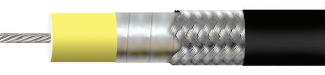
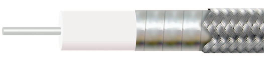
These scale drawings (approximately 50X actual size) illustrate IW’s unique Multi-Ply Laminate insulation that eliminates the problems which occur with other forms of construction.
Extruded Insulation requires a thicker insulating wall to compensate for the possibility of conductor eccentricity within the insulation.
Lap Wrap Tape Insulation creates an irregular surface which precludes use with “O” ring seals at high pressures; contamination on the tape surface creates a low resistance path; and a corona site forms in the triangular voids created where the tape overlaps.
1 2 3
IW’s Multi-Ply Laminate
Insulation, by contrast, delivers greater reliability with maximum space and weight savings.
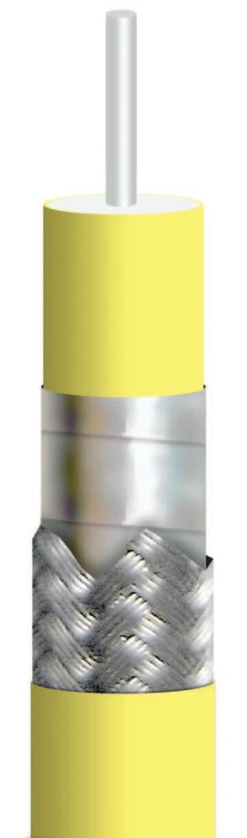

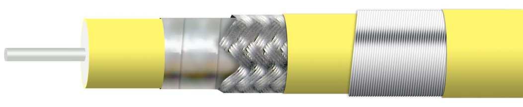
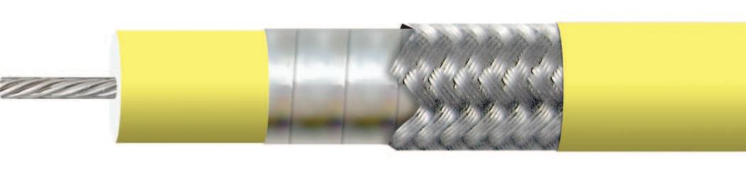
CENTER
CONDUCTOR
Silver plated per ASTM B-298
Multi-ply laminate Per Mil-C-17
Expanded PTFE Type F-6
Solid PTFE Type F-2
All materials per ASTM D 4894
SHIELD
Helically wrapped silver or silver plated copper foil
ASTM-B-298
BRAID
Silver plated copper per ASTM B-298. Braid coverage is greater than 98%
*Re昀氀ex per ASTM-B-33
JACKET FEP per ASTM D-2116
FAA Flammability Test
UL94-VØ


PowerHandling SeeChart SeeChart SeeChart SeeChart
CHARACTERISTICS
RoHS3(EU2015/863) Yes Yes Yes Yes
1 Standardcableassemblytemperaturerangeis
VSWRforassemblieswith twostraightconnectors
tworightangleconnectors
*Attenuation= K
(cableonly)
ELECTRICAL CHARACTERISTICS
Impedance 50+/–2Ω
CutOffFrequency(cableonly,max) 11.3GHz
Capacitance 24.5pF/ft.
VelocityofPropagation 83%
TimeDelay 1.22ns/ft.
ShieldingEffectivenessupto18GHz >90dB
CableAttenuationFactors* K1=2.9,K2=0.179
PowerHandling SeeChart
MECHANICAL CHARACTERISTICS
Weight 2.93oz/ft(272g/m)
StaticBendRadius 3.0”(76mm)
DynamicBendRadius 5.0”(127mm)
ENVIRONMENTAL CHARACTERISTICS
OperatingTemperatureRange
1 Standardcableassemblytemperaturerangeis
*Attenuation= K1
(cableonly)
CABLE ATTENUATION
CABLE SPECIFICATIONS
ELECTRICAL CHARACTERISTICS
Impedance 50+/–2Ω
CutOffFrequency(cableonly,max) 6.5GHz
Capacitance 24.5pF/ft.
VelocityofPropagation 83%
TimeDelay 1.22ns/ft.
ShieldingEffectivenessupto18GHz >90dB
CableAttenuationFactors* K1=1.9,K2=0.183
PowerHandling SeeChart
MECHANICAL CHARACTERISTICS
Weight 5.8oz/ft(536g/m)
StaticBendRadius 5”(127mm)
DynamicBendRadius 8.0”(203mm)
ENVIRONMENTAL CHARACTERISTICS OperatingTemperatureRange
(cableonly)
ELECTRICAL CHARACTERISTICS
Impedance
CutOffFrequency(cableonly,max) 18GHz
Capacitance
TimeDelay
ShieldingEffectivenessupto18GHz
CableAttenuationFactors(K1,K2)*
PowerHandling SeeChart
MECHANICAL
DynamicBendRadius 1.0”(25.4mm)
FEP Jacket available upon request *Attenuation=
Otherconnectortypesandstylesareavailable,pleasecontactthefactory
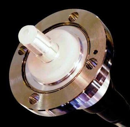
CONNECTORS FOR 750 SERIES
CONNECTORS
The outlines below show typical cable assembly con昀椀gurations and reference points to determine overall length.
Component
Bodies
CouplingNut
Contacts
MaterialSpeci昀椀cations
StainlessSteelper
AMS-5640UNS-S30300,Type1
StainlessSteelper
AMS-5640UNS-S30300,Type1
This catalog lists the most common con昀椀gurations for each cable type. If necessary, IW can modify existing designs or design a custom connector to meet your speci昀椀c requirements.
SolderFerrule
Dielectric
Gasket
BerylliumCopperperASTM-B-196
BrassperASTM-B-16
BrassperASTM-B-16
FinishSpeci昀椀cations
PassivationperSAE-AMS-2700
PassivationperSAE-AMS-2700
Our standard connectors meet the environmental speci昀椀cations of MIL-PRF-39012. Our N, TNCA and SMA connectors are optimized to be 18 GHz, all others meet applicable industry standards.
GoldPlatedperASTM-B-488
GoldPlatedperASTM-B-488
GoldPlatedperASTM-B-488
PTFE(polytetra昀氀uoroethylene)per ASTM-D-1710
Kel-FASTM-D-1430-03
ULTEM*(Grade1000)
*TrademarkGeneralElectricCorporation
SiliconeRubberperA-A-59588
VitonASTM-D-1418
*Acentermarkerlabelisfittedtoallassembliesover6”inlength;twomarkers locatedclosetothecableendsarefittedforasembliesgreaterthan10ft./120”/3m.
Note:ForRe-Flex™ assemblieswithSMAdirectsolderorshellstyleconnectors,thetolerancesare…
Shell type
SW Straight w/ wire holes
RC Right angle, cube body
RCD Right angle, cube body, direct solder
SQ Straight “Quik-Flex™”
A Stainless steel 昀氀exible armor
N Black neoprene jacket
NX Nomex
LC Low smoke / zero halogen polyurethane
† LC–LS/ZHjacketisavailablefor140-480 seriescables,including03/06/08;not
recommended for Re Flex™. LC jacket can be combined with external armor code ‘A’ for maximum crush resistance in outdoor environments.
†† Neoprene,‘N’canbeappliedtoallcable types.
Pleaseconsultthefactoryforcustom/ applicationspeci昀椀cjacketrequirements.
DIFFERENTIATOR CODES
1 Solid center conductor
3 Tuf-Flex™ solid center conductor
6 Stranded
With so many variables involved in creating custom wires for multiple purposes, IW has devised an Part Number (P/N) Coding System which we use to readily identify all our microwavecables.
DIFFERENTIATOR
J R 2 P S
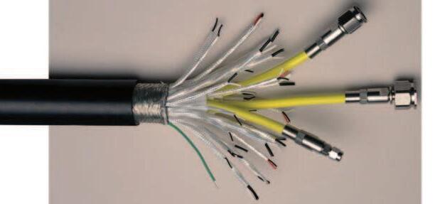
BESPOKEPROTECTION
Microwave transmission lines are quite often exposed to a wide range of hostile environments. These may include extreme temperature, abrasion, comprehensive forces, high pressure 昀氀uids, solvents, chemicals, salt water, UV, vibration, and mechanical stress, just to name a few.
In addition to our internally ruggedized cables, IW has a wide range of materials and processes designed to protect the integrity of our cable assemblies. These include a variety of metallic and non-metallic external sheaths to address your speci昀椀c application. Please contact us for details.
ZEL Tefzel™ jacket
Tefzel™ is a trademark of Chemours Company FC, LLC
NX Fire resistant Nomex® braid
Nomex® is a registered trademark of the DuPont Corporation
A Interlocked stainless steel armor, crush resistant up to 400 lbs per linear inch
N Neoprene weather proof jacket
ALC Interlocked stainless steel armor w/extruded Polyurethane jacket
SP Santoprene TPU extruded jacket
For applications where phase or electrical length is a critical performance parameter, IW can provide matched assembly sets, tested to customer speci昀椀cations, typically up to 40 GHz, with both Low Loss Phase Stable and Re-Flex™ cable types.
Relative phase matching is a common requirement achieved with multiple assembly sets. Typical phase matching tolerances are shown in Table 1 below.
Tighter tolerances may be achievable; IW engineers review all matching requirements on a case by case basis.
In addition, IW also provides time delay matched assemblies with tolerances in the order of 2pS being achievable with both Low Loss and Re-Flex™ cable types, and individual assemblies can also be supplied trimmed to a speci昀椀c electrical length.
All matched assemblies are tested 100% for insertion loss and VSWR performance parameters in addition to phase.
DETERMINATION OF PHASE CHANGE OVER TEMPERATURE
Thefollowingexampleillustrateshowtocalculatethe changeinphase(andthetrackingerror)ofcableassemblies overaspeci昀椀ctemperaturerange.Inthisexample,thecable isIW2801,andthetemperaturerangeis-40˚Cto+80˚C.
*determinedbythechartsabove **trackingerroroftwoormoreassembliesofthesametype
PHASE CHANGE WITH FLEXING
Phasechangewhen昀氀exingwillbeslightlydifferent dependingontheparticularcable.Largercableshave moredielectricandgreaterinternalforces,thusphase changewillbegreaterforcableswithlargerdiameters. Whenwrapped360˚arounda4inchdiametermandrel, thephasechangewillbe:
+0.30˚•f-forcables480,280,230,180and170
+0.20˚•f-forcables157,150and140
Frequency = 10 GHz f
Assembly length = 72 in L
Start temp = 20˚C T
Dielectric const = 1.4 e
Change in PPM = -500* PPM PPM tracking error = ±100 PPM tracking
Electrical length = TBD F
Change in phase = TBD DF
Tracking error = TBD** F tracking