
Coaxial Cable & Waveguide Connectors
Application Note
10000009163-01
Installation of Heat Shrink Sleeves
Heat Shrink Sleeves for additional sealing of Connectors
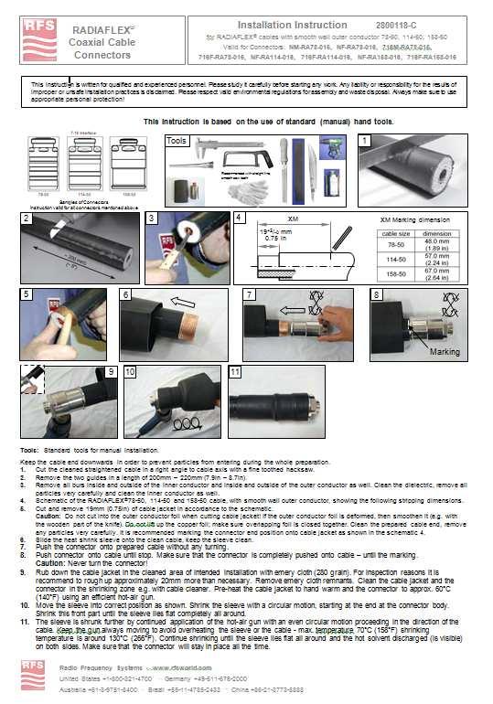
These instructions are written for qualified and experienced personnel. Please study them carefully before starting any work. Any liability or responsibility for the results of improper or unsafe installation practices is disclaimed. Please respect valid environmental regulations for assembly and waste disposal. Always make sure to use appropriate personal protection!
For the installation of a connector on a RADIAFLEX® cable with a copper foil outer conductor a heat shrink sleeve is mandatory. If using a CELLFLEX® connector for the RSF & RCF types of RADIAFLEX® cables a heat shrink sleeve has to be used in addition as well! Also for some FLEXWELL® waveguide connectors heat shrink sleeves are used for the sealing against the cable jacket.
A heat shrink sleeve can also be used as an additional sealing method for CELLFLEX® connectors e.g. for the C02 Series of connectors.
The following description shows the installation of a heat shrink sleeve on a RADIAFLEX® connector/cable, but the method of installation is valid for all the other configurations as well.
Install the connector carefully following the installation instruction of the connector.


Note: If the Interface is bigger in dimension than the sleeve size it is mandatory to put the sleeve onto the cable before starting with the connector installation. In such cases slide the sleeve onto the cleaned cable and fix it temporary e.g. with tape.
Installation of heat shrink sleeve:
Preparation of shrinking area:
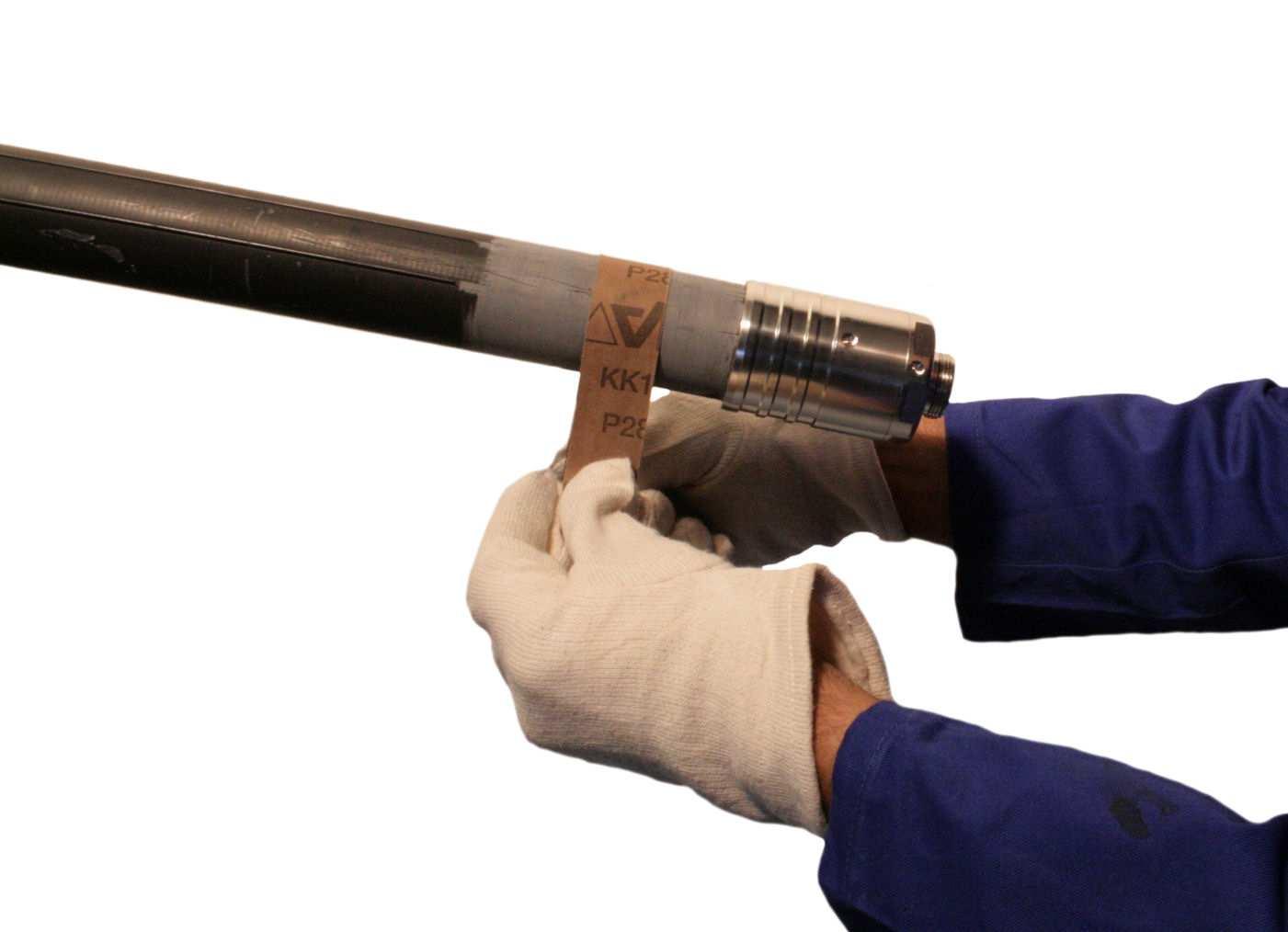
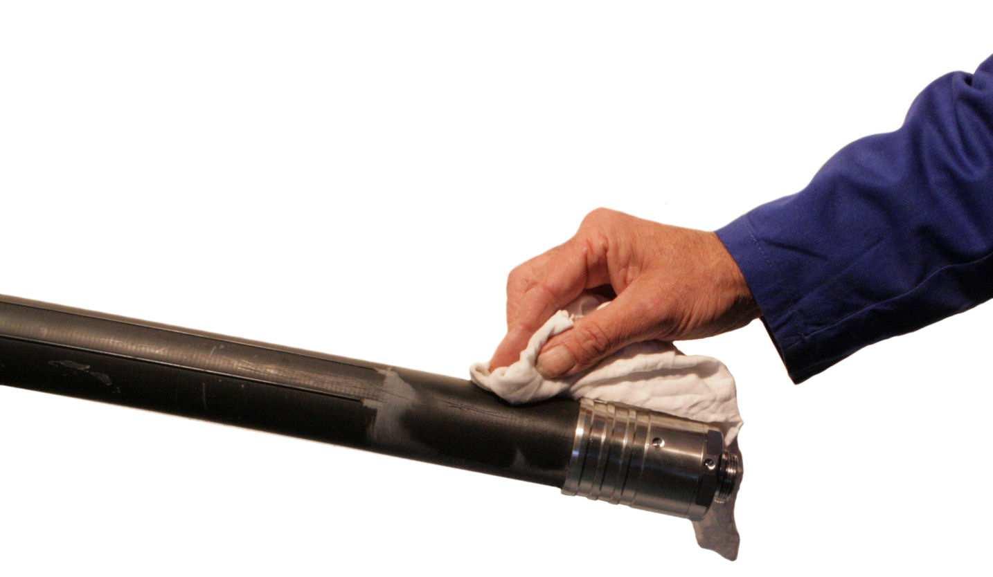
Rub down the cable jacket in the area of intended installation with emery cloth/sand paper (280 grain works fine). For inspection reasons it is recommended to rough up approximately 10-20 mm (0,4-0,8 in) more than necessary.
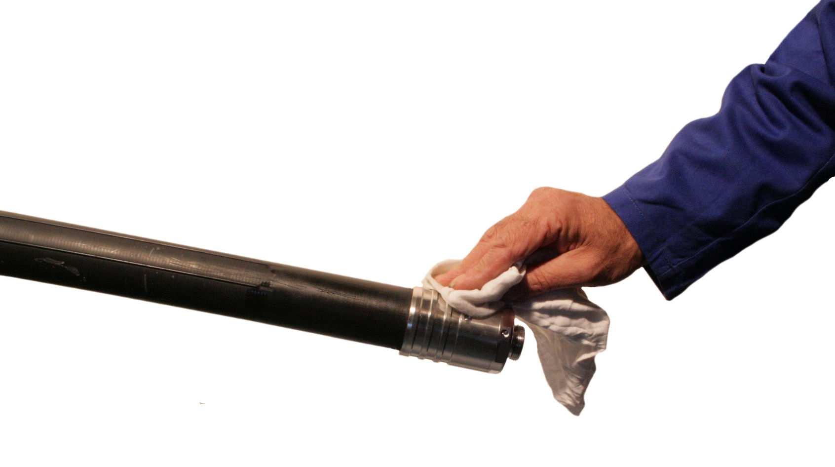
Remove emery cloth remnants with a clean cloth. Clean the cable jacket and the connector in the intended area with solvent cleanser e.g. with cable cleaner (e.g. CA-CLEAN-500), alcohol or spirit.
Coaxial Cable & Waveguide Connectors

Application Note
10000009163-01
Installation of Heat Shrink Sleeves
Heat Shrink Sleeves for additional sealing of Connectors
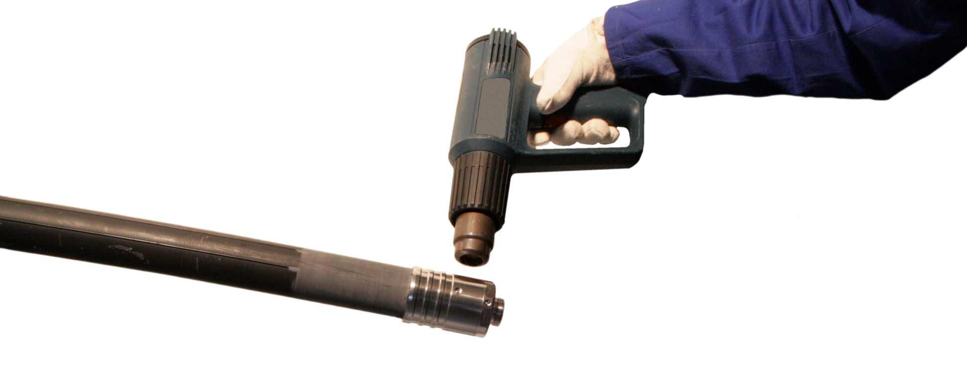
Safety precaution: Hot conditions => Protective / heat resistant gloves required!
Preparation
of shrinking area:
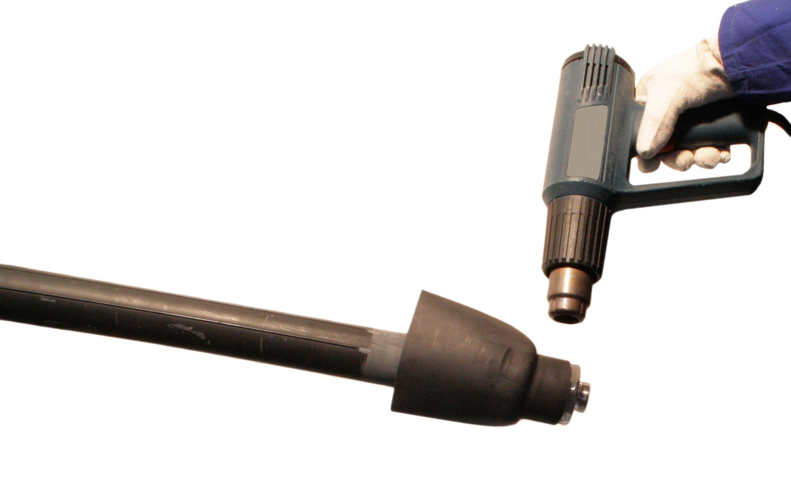
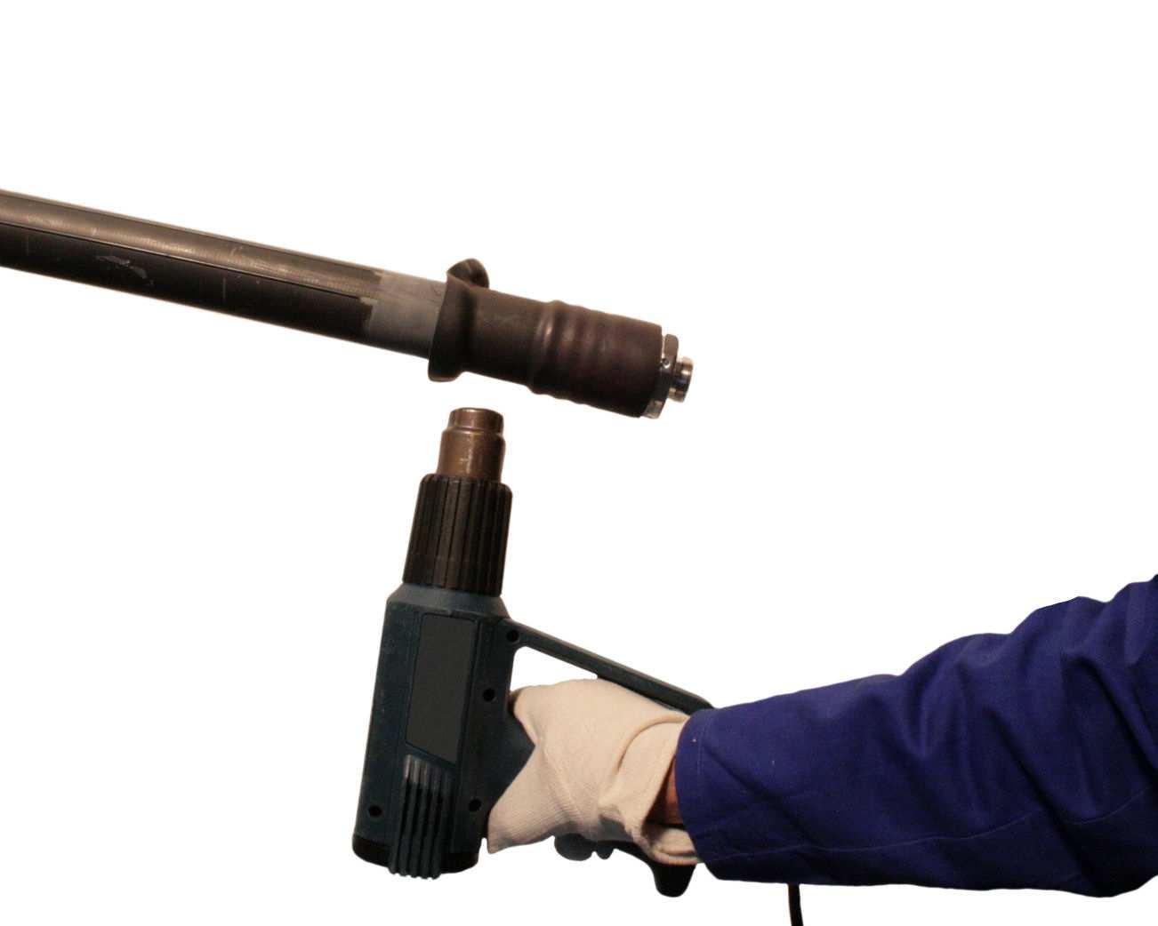
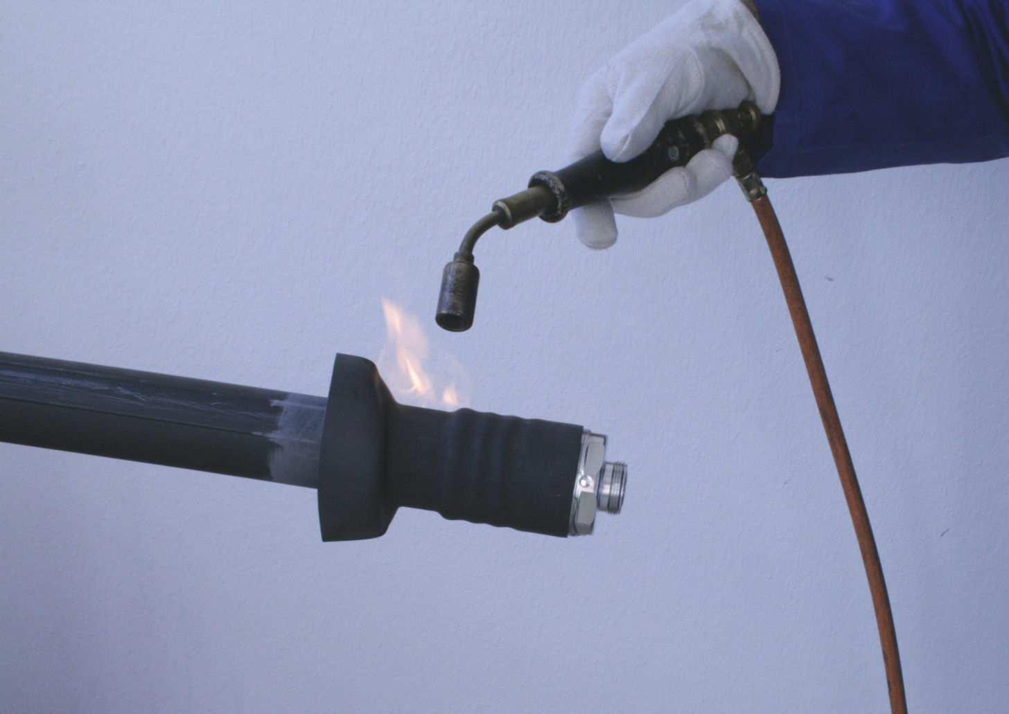
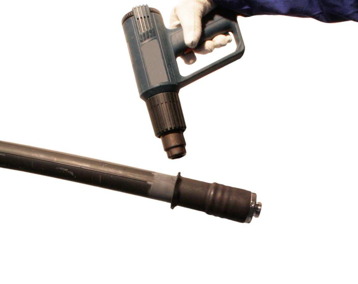
If existing remove the interface protection cap of the connector. Preheat the cable jacket to hand warm and the connector to approx. 60°C (140°F) using an efficient hot-air gun. When an efficient gas blow torch as heat source is used, work with an adjusted soft yellow flame (excess gas setting).
Safety precaution: e fluid far away from the place of work!
Installation of the sleeve:
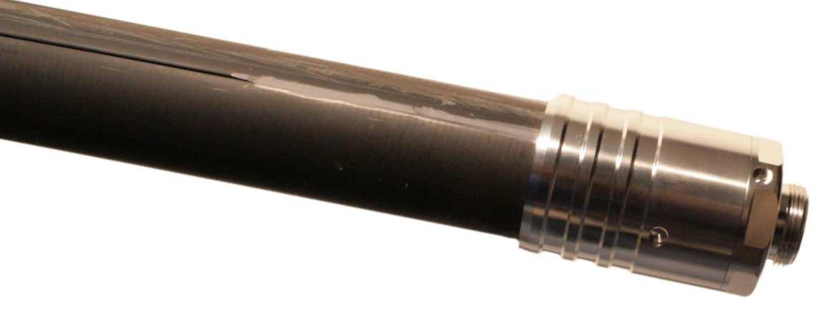
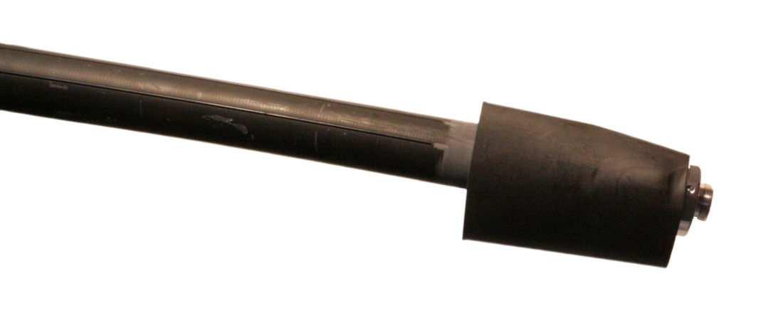
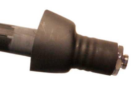
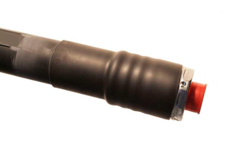
If existing remove adhesive strips from the sleeve. Keep the sleeve clean. Do not touch the sleeve inside with fingers. Slide the heat shrink into correct position as shown – take note of additional information in the installation manual of the connectors if relevant.
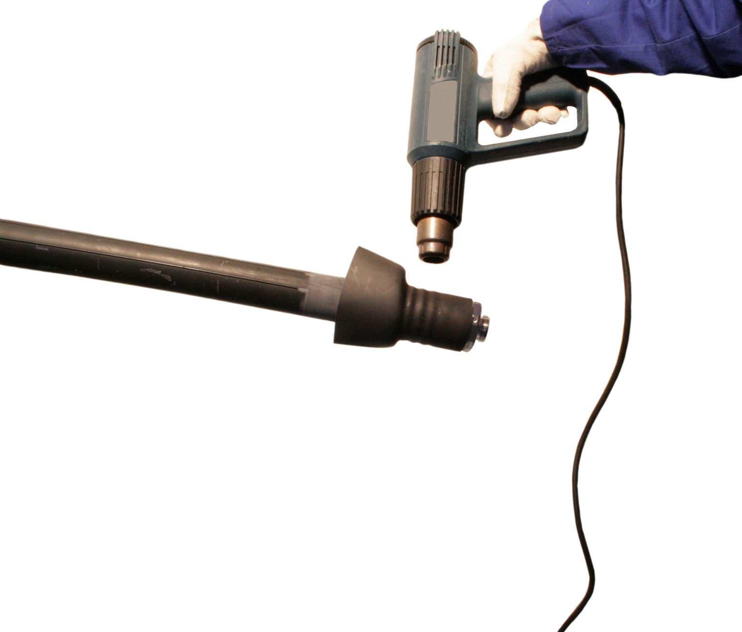
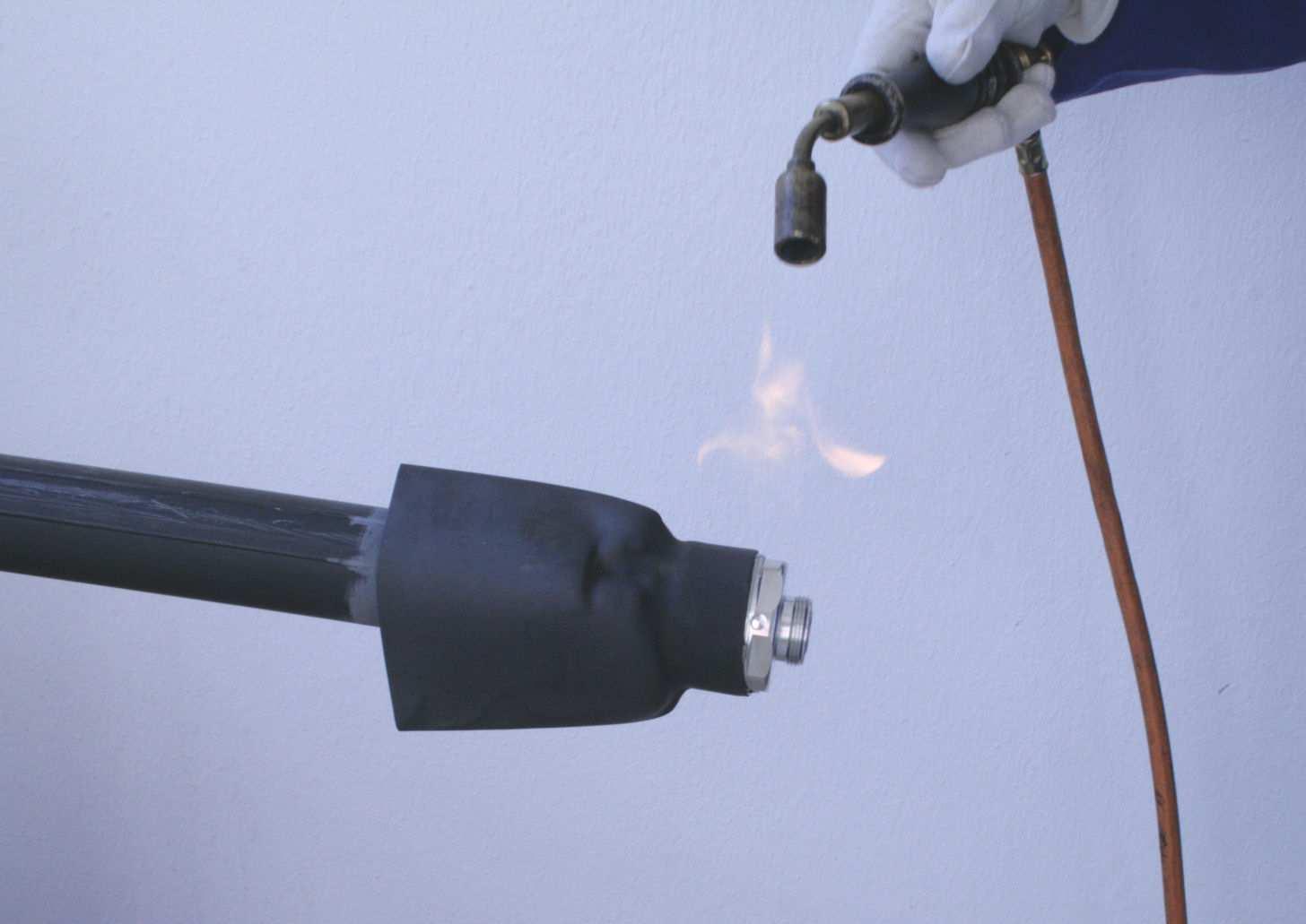
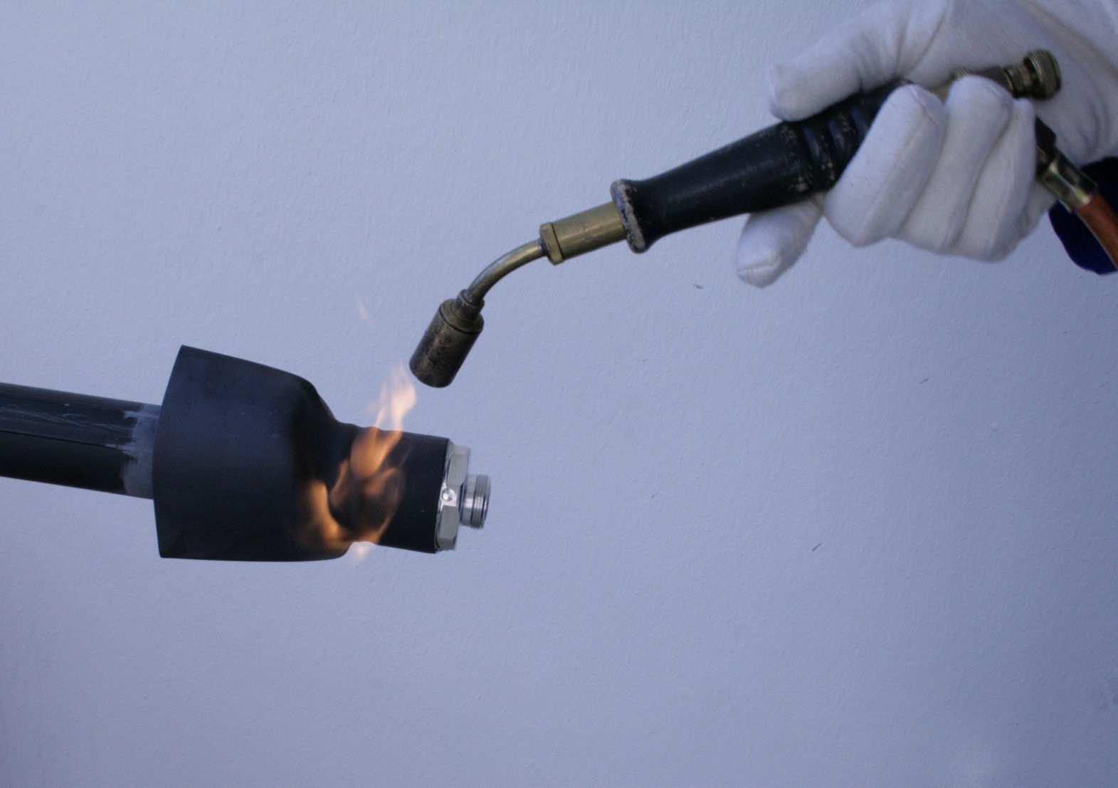
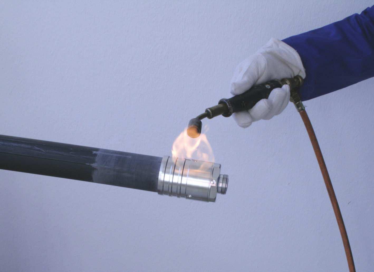
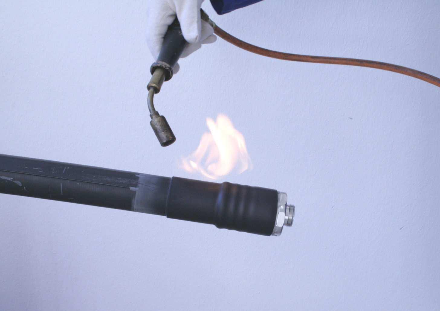
Shrink the heat shrink sleeve on the connector by uniformly applying a constant heat (flame) with a circular motion beginning at the connector front part.
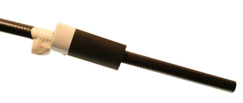
Shrink the front part until the shrink sleeve seats flush on the connector, and the hot melt adhesive emerges everywhere around the end. Keep steady moving the heat source to avoid burning the sleeve during the complete shrinking procedure.
Shrink the sleeve further to the end of the connector by continued application of the heat source with an even circulation motion. Do not overheat the sleeve. Keep the heat source at an angle that avoids local overheating of the heat shrink sleeve. Otherwise the heat shrink sleeve may sustain damage and burn. It may also tear around the burnt areas if the heat source is too close to the surface. Always watch out for air bubbles.
Coaxial
Application Note
10000009163-01
Installation of Heat Shrink Sleeves
Heat Shrink Sleeves for additional sealing of Connectors
After the sleeve is completely shrunk onto the connector it tends to move down from the bigger diameter connector when shrinking is continued on the cable. This can be avoided by making a short break in order to allow the sleeve to cool down in the front part. If working with a hot-air gun experienced riggers may work without a short break by keeping the sleeve in position with protected hands (using heat resistant gloves)Dangerous if working with a gas flame!
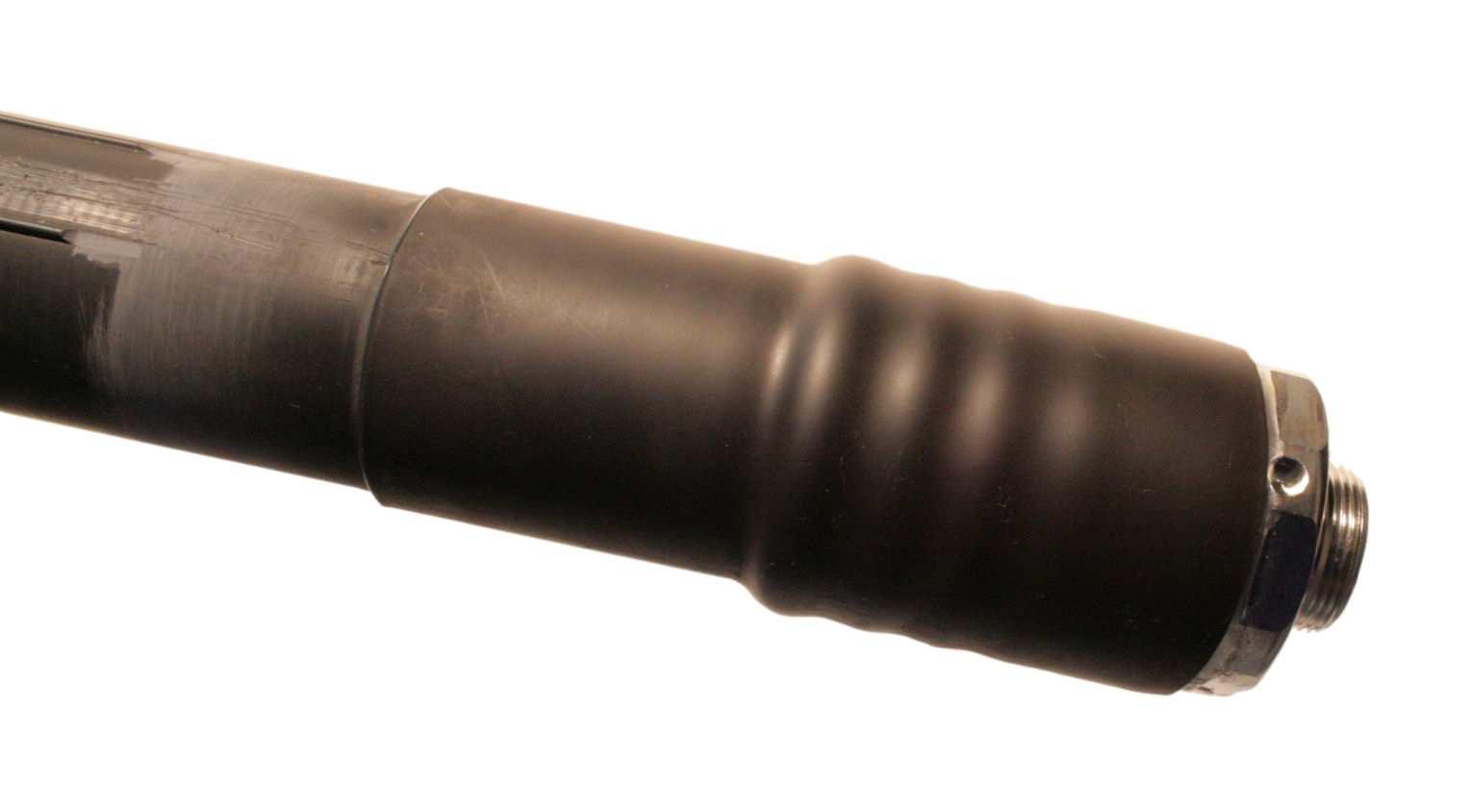
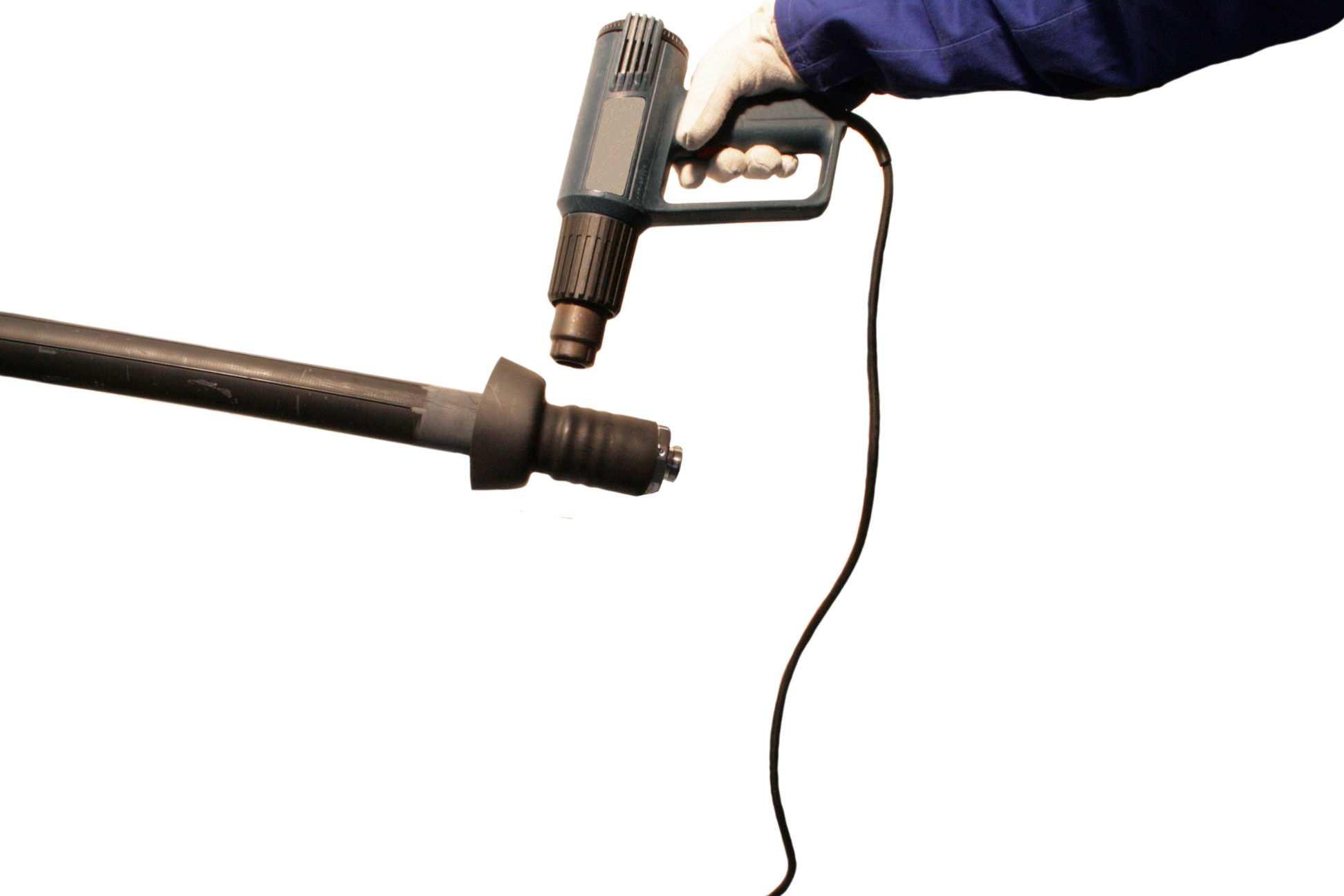
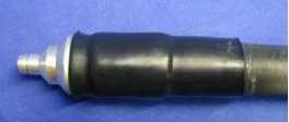
Continue shrinking the sleeve onto the cable by continued application of the heat source with an even circular motion. In order to avoid overheating of the cable jacket move the heat source in opposite side direction (away from the jacket) when shrinking the end of the sleeve – the max. cable jacket temperature is 70°C (158 °F), the shrinking temperature of the sleeve is ~ 130°C (266 °F), but the temperature of the heat source is subs tantially higher. During shrink down a quality check can be made (adhesive flow test), if moving/pushing the heat sleeve backwards the small fold/wrinkles in the collar will smooth themselves down (disappear automatically) if the hot solvent adhesive is sufficiently melted. The shrinking is completed when the heat shrink sleeve lays smooth all around the cable. The sleeve must be shrunk lengthwise as well; the ends are shrunk in a right angle to the cable axis. No bubbles, ripples or air pockets are visible; as well no signs of damages e.g. indicated by colour changes in the sleeve or other burn damages are visible. The hot solvent adhesive discharge is all around.
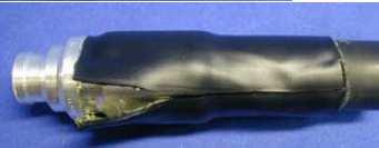
Bad examples:
Allow the sleeve to cool down before continuing the installation of the cable. In order to protect the interface of the connector place the protection cap back into place, if not existing use other useful protection material (e.g. a plastic bag).
The heat shrink sleeve on the cable side is not in a right angle to cable axis, this is evidence of not enough heating, in this case not enough heat on the bottom side, so the sleeve couldn’t shrink enough in this area. Also the sleeve had not enough temperature on the connector side, that’s the reason why the sleeve is lifting up on the connector front.
This deformed looking sleeve (cold spots) shows also that there was not enough heat. After opening the sleeve it can be seen that there is no bond to the connector.
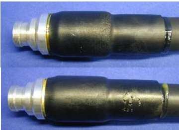
Because of too much heat or not enough movement of the heat source the sleeves are damaged (burned).