

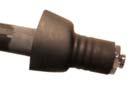
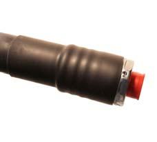
RADIAFLEX® Cables 1 1/4” & 1 5/8” Premium Connectors –P02 series
These instructions are written for qualified and experienced personnel. Please study them carefully before starting any work. Any liability or responsibility for the results of improper or unsafe installation practices is disclaimed. Please respect valid environmental regulations for assembly and waste disposal. Always make sure to use appropriate personal protection!


Installation Instruction 10000014944-02
RADIAFLEX® Cables 1 1/4” & 1 5/8”
Premium Connectors –P02 series


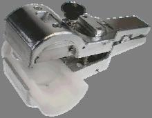
Installation method with Universal Trimming Tool
TRIM-SET-R114-P02 for 1 ¼” or TRIM-SET-R158-P02 for 1 5/8”
Consist of:
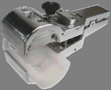
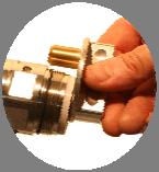
Body: TRIM-U-114-158
Flaring tool: TRIM-FL114-158
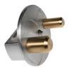
Insert: TRIM-IR114-P02 or TRIM-IR158-P02
Insert consist of:
Installation Instruction
10000014944-02
RADIAFLEX® Cables 1 1/4” & 1 5/8”
Premium Connectors –P02 series
Blade holder: TRIM-IR114-P02 or TRIM-IR158-P02
Collet: TRIM-IR114
Note: For the inserts for RADIAFLEX® cables special blades are used. Do not use a blade which is made for the inserts for CELLFLEX® cables and vice versa!
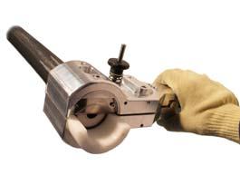
Please refer to the instruction of the Universal Trimming Tool in addition!
Attention:
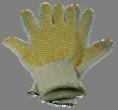
Trimming tool to be handled and used with great care, blades are extremely sharp! It is recommended to use protective gloves. Do not use great force.
Keep the cable end downwards in order to prevent particles from entering during preparation. For optimum PIM performance we recommend to install the connector at a location where the outer conductor does not show slots in the dismantled area.
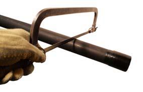
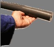
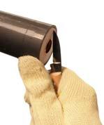
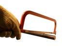
1. Straighten the cleaned cable end in a length of min. 500 mm (20 in). Cut of the end section if not straight able.
2. Slide with a knife atop the cable jacket in order to remove the two guides in a length of min. 250 mm (10 in).
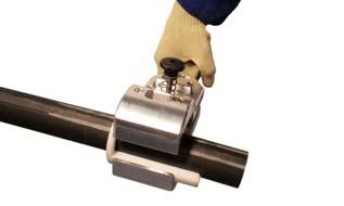
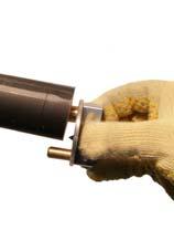
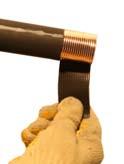
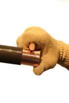
3. Open the Universal Trimming Tool by pressing the base and the top handle together and insert the cable as shown. At least 50 mm (2,0 in) ahead of the cable end should protrude from the tool.
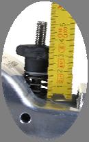
4. Keep the tool in this position and turn the hand wheel in order to tension the spring. Turn the hand wheel until the shown distance (Length of the spring) of 16 – 17 mm (0,63 – 0,64 in) is set. As shown at the picture, for this adjustment the flaring tool of the preparation tool can be used for checking the distance.
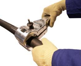
5. Rotate the Universal Trimming Tool around the cable in direction of the arrow shown on the tool until the jacket, the outer conductor and a part of the dielectric have been cut. Maintain a straight line while turning the tool around the cable – do not shift the tool laterally. While continue turning hold the cable end in position to ensure that the cut cable end cannot move or bend in any direction.
6. Once the cable is completely cut after several turns, continue turning the tool min. 3 more times around the cable in order to make sure the jacket will be cut as well.
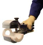
7. Unfasten the tool by turning the hand wheel in opposite (counter clockwise) direction and remove the tool by pressing the handles together.
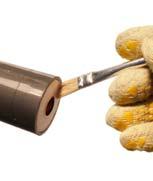
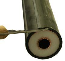
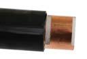
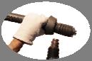
8. Clean the cable end, remove any particles very carefully. Particles which are inside the inner conductor can be removed by knocking the cable carefully from the bottom side, as well by the use of a brush in order to clean the inner conductor completely. Also remove any particles from the dielectric very carefully e.g. using a knife and a brush. It is not recommended to use steel or similar hard brushes, because these can deeply press particles inside the dielectric. Adhesive tape can be used additionally to remove the finest particles.
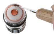
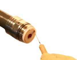
9. If the inner conductor has been deformed (from cutting), insert the cable guide pin of the flaring tool and forme it carefully back into round shape. Take care; do not insert the complete guide pin in order to avoid damaging the already prepared cable end with the flaring pin of the flaring tool (the flaring pin is need only for a later step).
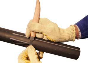
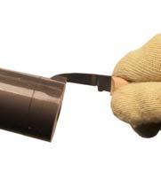
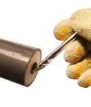
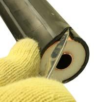
10. Carefully cut the cable jacket lengthwise with a knife, do not cut the jacket completely – cutting a little more than half of the sheath thickness is sufficient. Do not damage the copper foil outer conductor! Stick a knife into the front part of the jacket - not between jacket and copper foil - and lift the jacket. Remove the jacket through tear, plies can be used carefully. Do not lift the copper foil; make sure that the overlapping foil is closed together. For optimum PIM performance we recommend to repeat the cable cutting if the outer conductor shows slots in the dismanteled area. Repeat the cable cutting until there are no slots in the contact area of the connector.
11. If the outer conductor foil is slightly deformed, then smooth the foil e.g. with the wooden knife handle.
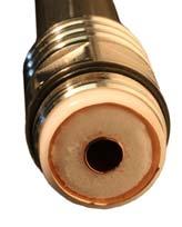
12. Check the trimming dimension of the jacket.
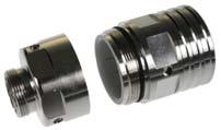
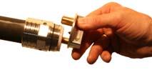
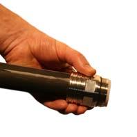
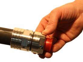
13. Keep the connector in a straight line while carefully pushing the connector back-part onto the prepared cable end until stop at the jacket and the outer conductor is flush with the connector back part. Do not turn the connector while pushing because this will damage the copper foil outer conductor!
14. Push a bit of dielectric to the centre in order to have a free space to insert the flaring pin of the tool as required for the next step.
RADIAFLEX® Coaxial Cable Connectors
Installation Instruction
10000014944-02
RADIAFLEX® Cables 1 1/4” & 1 5/8”
Premium Connectors –P02 series
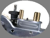
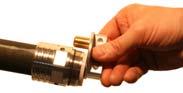
15. Check the position of the overlapping copper foil of the outer conductor. Insert the intended cable insert guide of the flaring tool into the inner conductor, make sure that the flaring pin is located between outer conductor and foam/dielectric – in the free space made before. Find out the correct turning direction: in order to avoid deformation of the copper foil the flaring pin should slide below the copper foil without the possibility to bend the inner part more to the inside. Keep pushing the tool to the cable while turning min.2 times to flare the outer conductor. Flare diameter has to be evenly round and concentrically to the cable axis.
16. Clean the prepared cable end again, remove any particles very carefully. Tip: tape can be used additionally to remove the finest particles.
17. Careful preparation is the key for good VSWR and especially for proper PIM performance. Flare diameter has to be evenly round and concentric to the cable axis. The flared area (cone) has to be free of any dielectric material, if necessary bend the dielectric back to centre.
18. Push connector front part onto prepared cable end, do never turn the front part, because this will damage the copper foil outer conductor and can damage the inner as well!
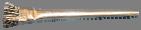
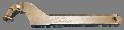
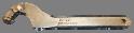
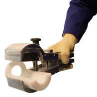
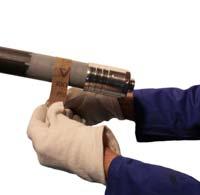
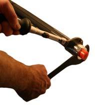
19. Pay attention to straight position of connector parts and keep the connector front-part steady while pushing the front part onto cable. Continue constantly pressing all the time while tightening the connector by turning the back-part only (first by hand). Never turn the front part of the connector. Keep the connector body steady and tighten the back-nut of the connector by the use of two poly hook spanners (e.g. PHS60-90-5 or comparable ones). Tighten the connector properly, recommended torque is 45 – 50 Nm (33,2 – 36,8 ft.-lb).
The pictures of the following installation of the heat shrink sleeve are shown as an example. The instruction are valid to all other connector types and sizes as well.
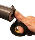
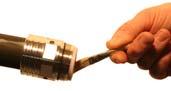
20. Rub down the cable jacket with emery cloth/sand paper (280 grain works fine) in the length as shown. For inspection reasons it is recommended to rough up approximately 10-20 mm (0,4-0,8 in) more than necessary.
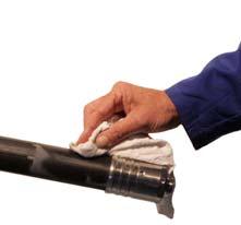
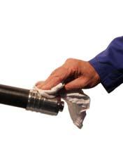
21. Remove emery cloth remnants with a clean cloth. Clean the cable jacket and the connector in the intended area with solvent cleanser e.g. with cable cleaner, alcohol or spirit.
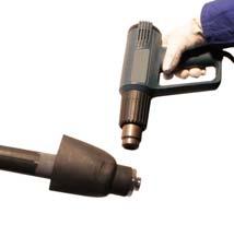
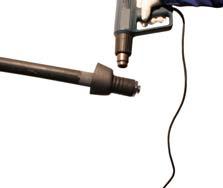
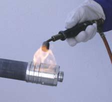
22. Remove the interface protection cap. Pre-heat the cable jacket to hand warm and the connector to approx. 60°C (140°F) using an efficient hot-air gun. When an efficient gas blow torch as heat source is used, work with an adjusted soft yellow flame (excess gas setting).
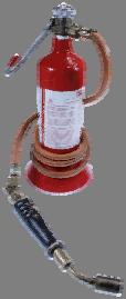
Safety precaution: Put the closed canister/bottle with the inflammable fluid far away from the place of work!
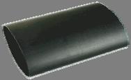
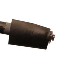
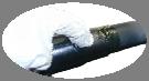
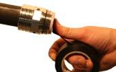
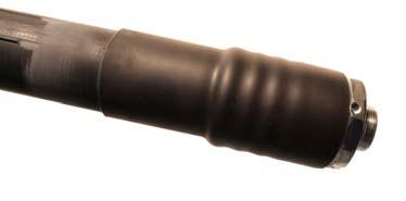
23. Slide the heat shrink into correct position as shown.
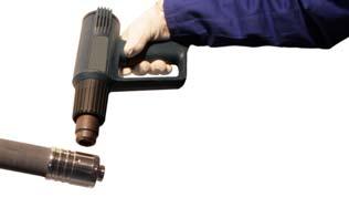
24. Shrink the heat shrink sleeve on the connector by uniformly applying a constant heat (flame) with a circular motion beginning at the connector front part. Shrink the front part until the shrink sleeve seats flush on the connector, and the hot melt adhesive emerges anywhere around the end. Keep steady moving the heat source to avoid burning the sleeve during the complete shrinking procedure.
Shrink the sleeve further to the end of the connector by continued application of the heat source with an even circulation motion. Do not overheat the sleeve. Keep the heat source at an angle that avoids local overheating of the heat shrink sleeve. Otherwise the heat shrink sleeve may sustain damage and burn. It may also tear around the burnt areas if the heat source is too close to the surface. Always watch out for air bubbles.
25. When the sleeve is completely shrunk onto the connector the sleeve tends to move from the connector if continue shrinking on the cable. This can be avoided by making a short break in order to allow the sleeve to cool down in the front part. If working with a hot-air gun experienced riggers may work without a short break by keeping the sleeve in position with protected hands (using heat resistant gloves) - Dangerous if working with a gas flame!
26. Continue shrinking the sleeve onto the cable by continued application of the heat source with an even circular motion. In order to avoid overheating of the cable jacket move the heat source in opposite side direction (away from the jacket) when shrinking the end of the sleeve – the max. cable jacket temperature is 70°C (158°F), the shrinking temperature of the sleeve is ~ 130°C (266°F), but the temperature of the heat source is substantially higher. During shrink down a quality check can be made (adhesive flow test), if moving/pushing the heat sleeve backwards the small fold/wrinkles in the collar will smooth themselves down (disappear automatically) if the hot solvent adhesive is melted enough. The shrinking is completed when the heat shrink sleeve lays smooth all around the cable. The sleeve must be shrunk lengthwise as well, the ends are shrunk in a right angle to the cable axis. No bubbles, ripples or air pockets are visible; as well no signs of damages e.g. indicated by colour changes in the sleeve or other burn damages are visible. The hot solvent adhesive discharge is all around.
27. Allow the sleeve to cool down before continue the installation of the cable. In order to protect the interface of the connector place the protection cap back into place.