






®


®
Description
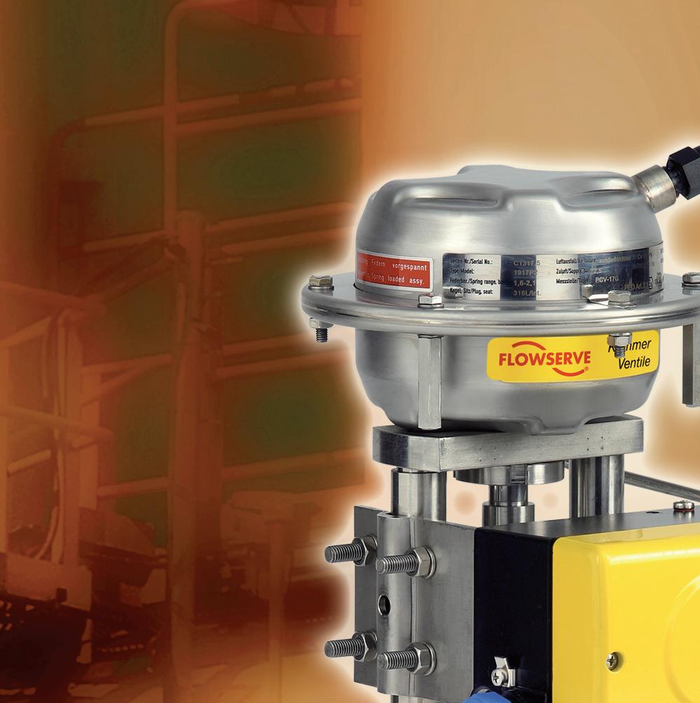
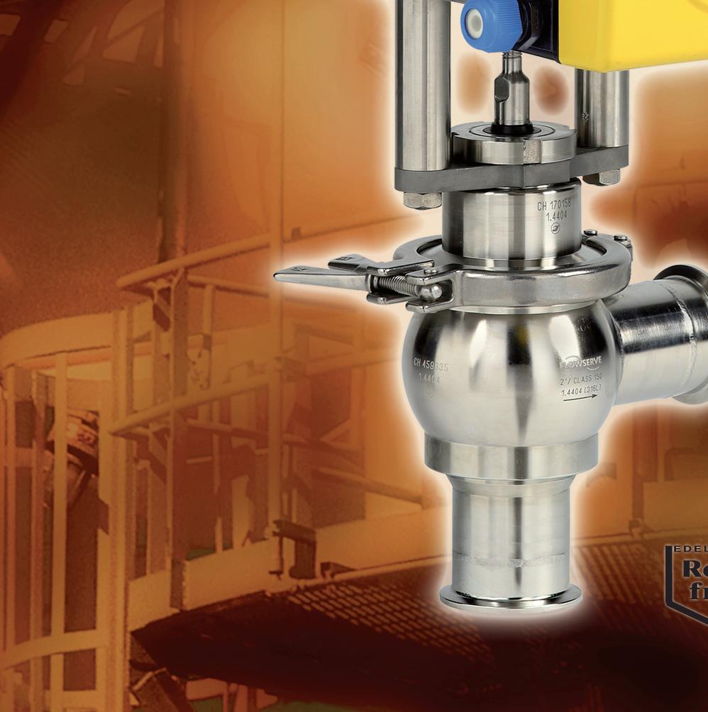
The Kammer 191000 Series product line provides control valve solutions for sanitary and aseptic process systems. These valves meet the standards for cleaning in place (CIP) and sanitizing or steam in place (SIP). They are designed to drain freely from inlet to outlet. In sanitary and aseptic valve applications, the surface finish of all wetted parts is of the utmost importance and need to be free of pits and cracks. The Kammer 191000 Series valves meet all of these requirements.
The Kammer 191000 Series control valves have a wide range of applications in many industries including food and beverage, biotech, pharmaceutical and others where perfect cleanliness and sterile valves are required. The valves are designed for easy maintenance and all parts in contact with the media are made of corrosion resistant materials including 316 L Stainless Steel, PTFE, TFM or silicon.
For the aseptic version of this valve series, a TFM diaphragm seals the media from the environment. The result is a pure aseptic valve design, free from residue or organisms left behind after cleaning thus eliminating any potential source of product contamination. These valves have excellent hygienic properties.
The standard surface finish for all 191000 Series valves is 24 Ra microinch. For aseptic applications, the standard surface finish is 15 – 20 Ra microinch (electro-polished). FLOWSERVE can also provide a better quality surface finish than 15 – 20 Ra microinch as a standard option where required for specific applications.
All of these valve designs carry 3A and USDA approvals.
Figure 1 shows our standard sanitary valve series 191400. This valve type is used for food and beverage applications. Figure 2 shows the aseptic valve series 191800. This valve type is used in pharmaceutical and biotech applications.


Features
Body
Connections
Aseptic diaphragm
Table 1: Body
Advantages
One valve body design utilizes different bonnet options for various sanitary and aseptic applications. All valve bodies are self-draining, pocket free and meet CIP and SIP standards.
Because of various end connection options these valves can be installed in almost every plant.
The aseptic diaphragm for the versions 191700 and 191800 is made of a combination of TFM on media side and EPDM as the base material. This diaphragm is FDA approved.
Material 316L (1.4404)
Sizes
Pressure class
DIN PN 10 (191700 - 191800)
DIN PN 16 (191400)
ANSI Class 150
Table 2: Connections
DIN 32676 clamped
ISO 2852 clamped
DIN 11850 Reihe 2 (DN10 - 100) weld ends
ISO 2037 / BS 4825 weld ends
DIN EN ISO 1127 weld ends
DIN 11851 threaded connection
DIN 11864 Form A threaded
DIN 2526 flanged PN 10
Others upon request

Type
Table 3: Bonnet
Standard bonnet (3A) Aseptic bonnet w/o test port Aseptic bonnet with test port ¼˝ NPT
Aseptic diaphragm TFM / EPDM - acc. to FDA
Packing Silicon O-Ring acc. to FDA (191400 / 191800) Without - (191700)
Table 4: Specials
Surface finish Ra 24 microinch (std / sanitary) Ra 15-20 microinch (std. / aseptic) Others available on request
Approvals 3A, FDA, USDA
Table 5: Plug
Material 316L SS (1.4435) standard Alloy 6 (optional)
Characteristics Equal percentage Linear On - Off
The type 191400 is the prime choice for nearly all applications in the food and beverage industry. Because of it’s optimized body design the valve is pocket free so that bacteria or any other kinds of contamination are avoided. The seat is an integral part of the body to avoid additional gaps. The O-Ring packing and general bonnet design ensure a very compact overall height. The stem is guided by a PTFE bushing for precise control, reduced friction and minimal wear. A wiper ring is provided to protect against contamination from the outside. Repair and maintenance are easy to perform because the body / bonnet connection utilizes a tri-clamp.
3: Typ 191400
The Type 191400 is designed in accordance with 3A and USDA (United States Department of Agriculture) requirements. Leakage can be very quickly detected by a system of holes drilled into the bonnet and the body. The hole in the bonnet is connected to a circular groove just above the O-Ring. Any media leaking past the O-Ring can flow thought the holes to the outside and is readily visible. The hole in the body is situated within the body and bonnet clamp enclosure to prevent the ingress of contamination from the outside. The stem O-Ring is located very close to the lower end of the bonnet to ensure that the gap between the stem and the bonnet is as small as possible.
PTFE guide
Bushing
O-Ring - stem seal
O-Ring - body seal
Stem with plug
Valve body


Both valve types 191700 and 191800 were developed for aseptic applications in the pharmaceutical industry as well as biotechnology and ultra clean applications. An aseptic diaphragm made from EPDM with a TFM coating is used to seal the media from the environment. To extend the lifetime of the diaphragm a support ring is installed on it’s reverse side. For different applications there are two options available. Type 191700 with aseptic diaphragm without a stem O-Ring seal but with leakage detection hole in case of diaphragm damage. Type 191800 with an additional O-Ring seal and ¼˝ NPT test port for leak detection. Both versions use the same body, aseptic diaphragm and plug heads but have different bonnets and stems.
The 191800 aseptic type valve uses an O-Ring seal on the stem (above the diaphragm) and a 1/4˝ NPTF test port connection for leak detection in case of a diaphragm failure. The outside radius of the aseptic diaphragm is clamped between the body and bonnet and also serves as the body gasket. The valve is equipped with the standard diaphragm support ring. The screwed plug design allows for easy replacement of the aseptic diaphragm or the valve plug, independently from one another.
Test connection 1/4˝ NPTF
Aseptic bonnet 191800
O-Ring stem seal
Plug - threaded
PTFE guide
Clamp
Diaphragm support ring
Aseptic diaphragm

Contrary to the type 191800 aseptic valve style, the 191700 version does not have a test connection port. Possible leaks are detected in the same way as the standard type 191400 sanitary valve, through small holes in the bonnet and body. The hole in the body is situated within the body and bonnet clamp enclosure to prevent the ingress of contamination from the outside. All other features of the aseptic valves including diaphragm support ring and the screwed plug head – diaphragm – stem connection are standard on the type 191700 valve.
Aseptic bonnet 191700
Figure 6: Type 191700 3A design
Table 7: Cv values
0.0470.12E0.12 0.0740.12D0.12 0.120.12C0.12 0.190.12B0.12 0.290.12A0.12 0.470.18B0.18 0.740.18A0.18 1.20.28B0.28 1.90.28A0.28 2.90.400.40 4.70.480.48 7.40.630.63 120.800.80 191.001.00 291.251.25 471.601.60 742.002.00 1202.502.50 1903.203.20
Rangeability: 50:1 Plug material: 316L (1.4435)
Worldwide Regional Headquarters
Flowserve Corporation
Flow Control
1350 N. Mt. Springs Parkway Springville, UT 84663
USA
Phone: +1 801 489 8611
Fax: +1 801 489 3719
Kämmer Products Americas
Flowserve Pittsburgh
Kämmer Valves
1300 Parkway View Drive Pittsburgh, Pa 15205
USA
Tel.: +1 412 787 8803
Fax: +1 412 787 1944
Flowserve Corporation has established industry leadership in the design and manufacture of its products. When properly selected, this Flowserve product is designed to perform its intended function safely during its useful life. However, the purchaser or user of Flowserve products should be aware that Flowserve products might be used in numerous applications under a wide variety of industrial service conditions. Although Flowserve can (and often does) provide general guidelines, it cannot provide specific data and warnings for all possible applications. The purchaser/user must therefore assume the ultimate responsibility for the proper sizing and selection, installation, operation, and maintenance of Flowserve products. The purchaser/user should read and understand the Installation Operation Maintenance (IOM) instructions included with the product, and train its employees and contractors in the safe use of Flowserve products in caonnection with the specific application.
While the information and specifications contained in this literature are believed to be accurate, they are supplied for informative purposes only and should not be considered certified or as a guarantee of satisfactory results by reliance thereon. Nothing contained herein is to be construed as a warranty or guarantee, express or implied, regarding any matter with respect to this product. Because Flowserve is continually improving and upgrading its product design, the specifications, dimensions and information contained herein are subject to change without notice. Should any question arise concerning these provisions, the purchaser/user should contact Flowserve Corporation at any one of its worldwide operations or offices.
© 2006 Flowserve Corporation, Irving, Texas, USA. Flowserve is a registered trademark of Flowserve Corporation.

Local Contact:

1500 E. Burnett St. Signal Hill, CA 90755
Tel: 562-595-8773
Email: Sales@BV-BM.com
3800 Fruitvale Avenue Bakersfield, CA 93308
Tel: 661-589-6801
Email: Sales@BV-BM.com
Serving CA, NV, AZ Industry Since 1954
Website: WWW.BV-BM.COM
08/12
3195 Park Road, Benicia, CA 94510
Tel: 707-590-6688
Email: Sales@BV-BM.com