


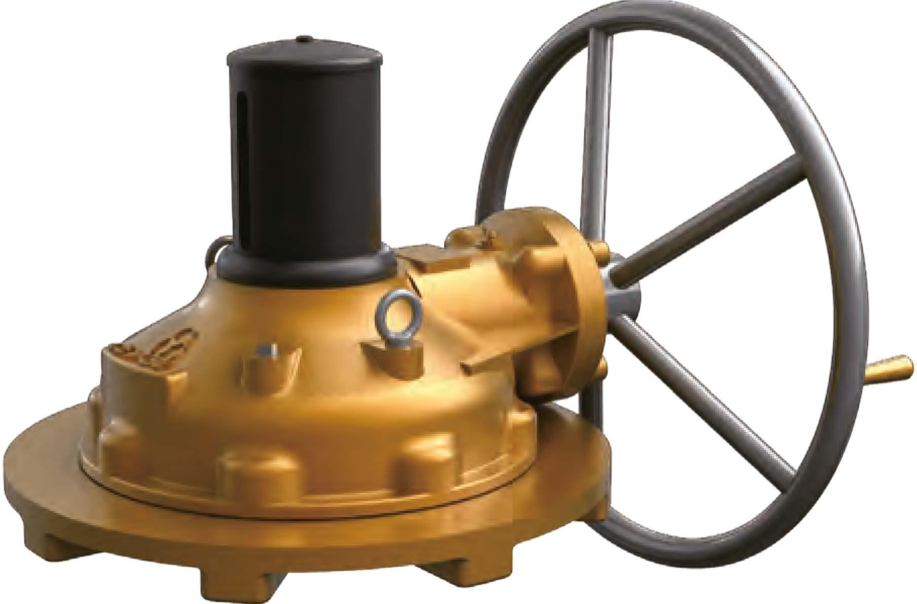
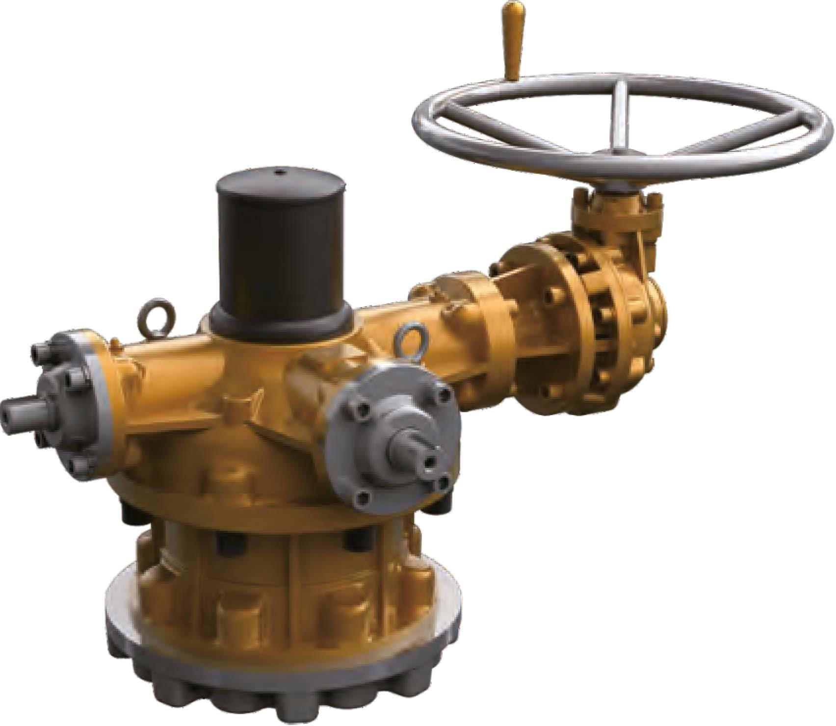
SpurGearActuators >> WormGearActuators >>>


SpurGearActuators >> WormGearActuators >>>
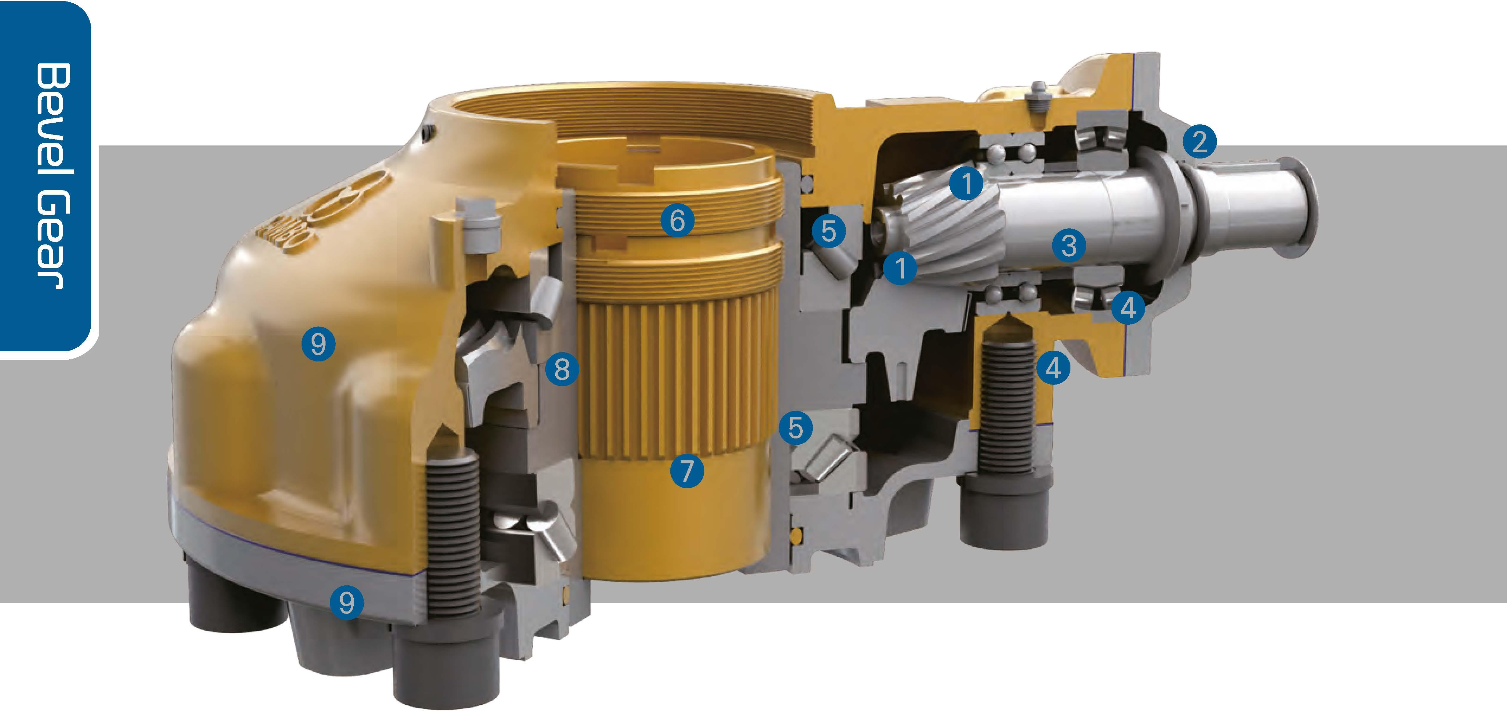
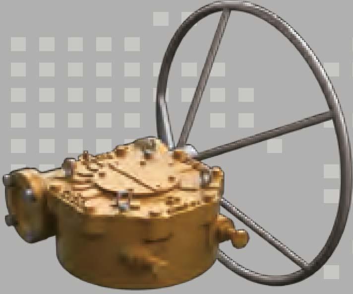
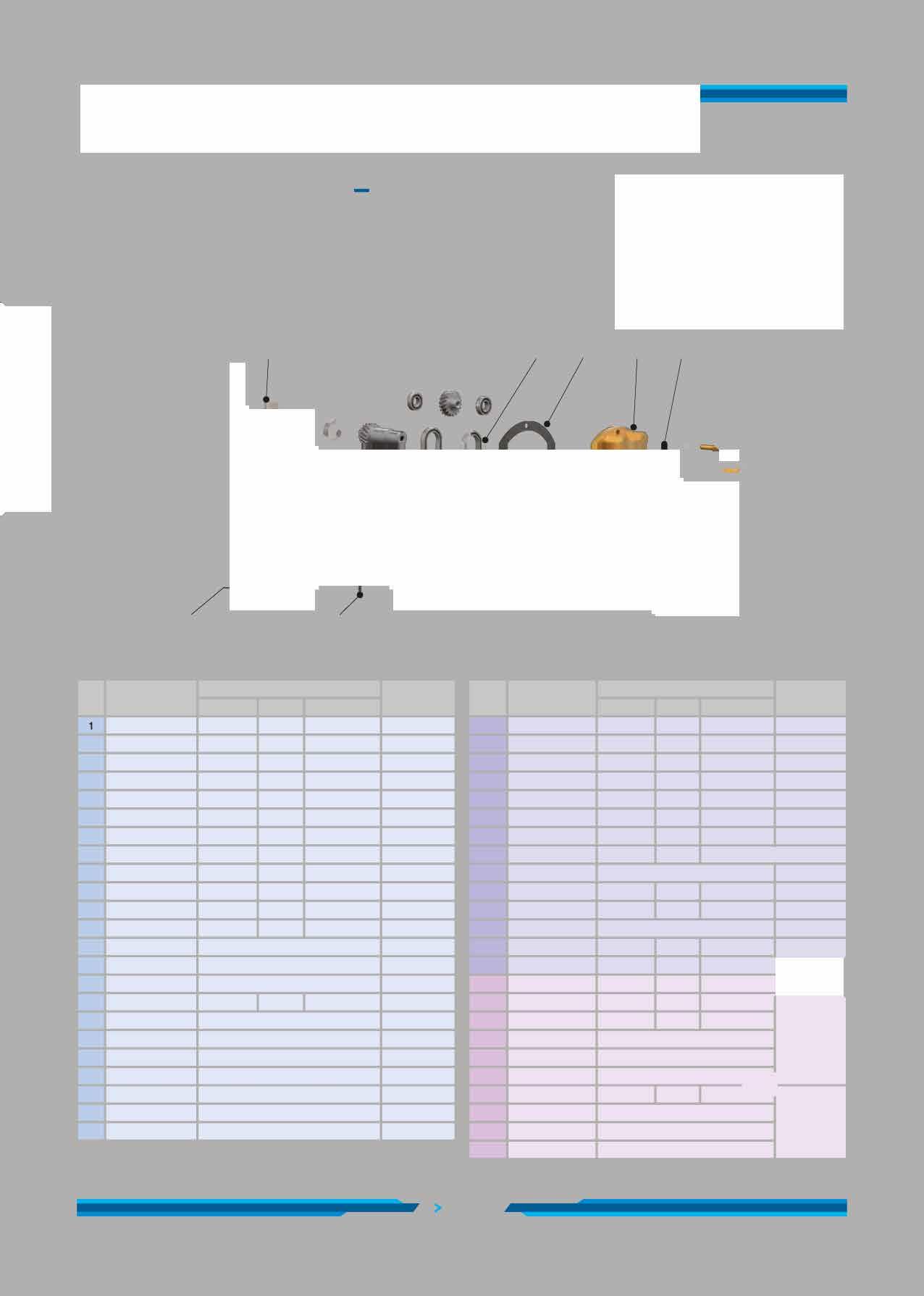
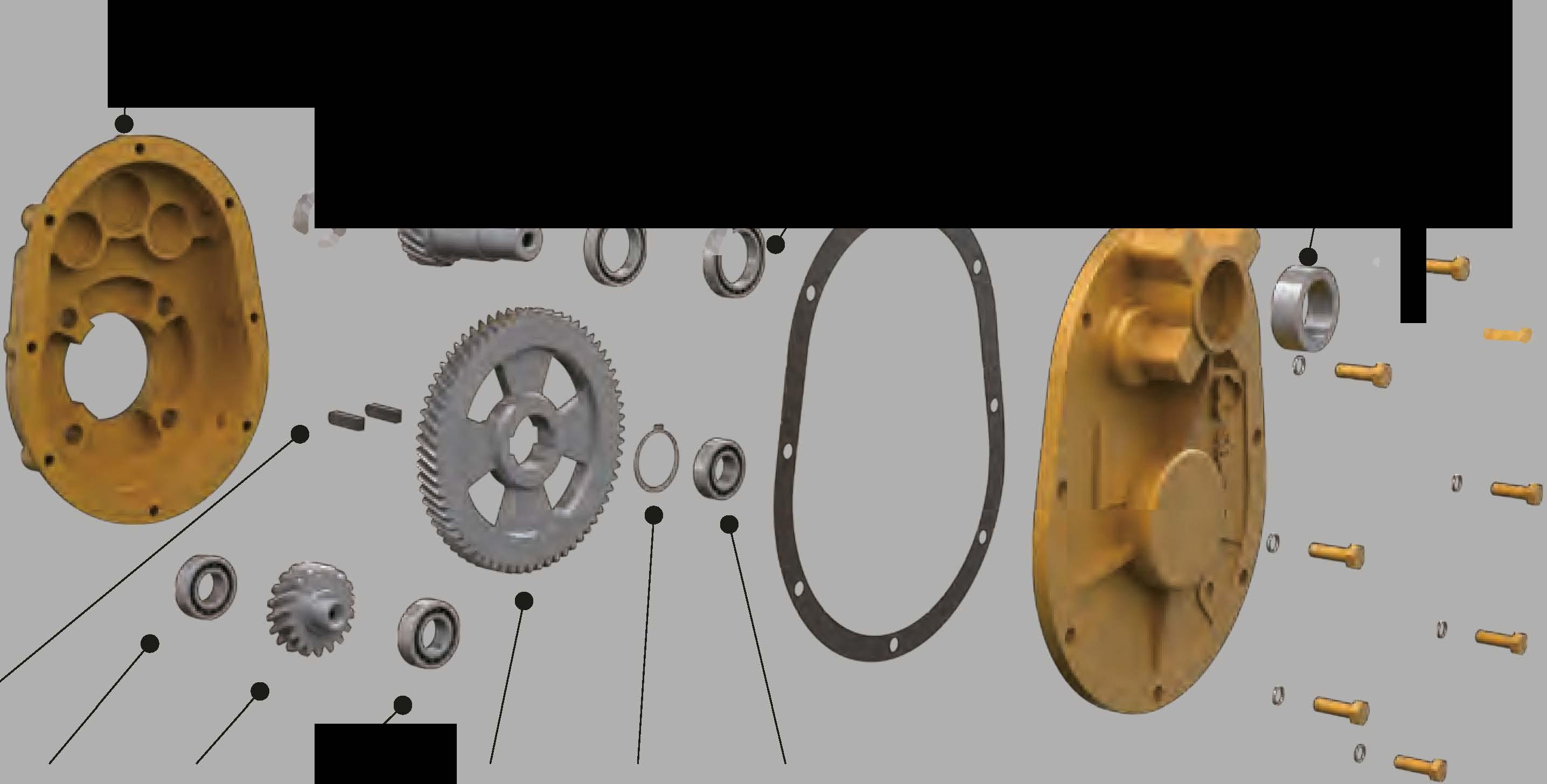
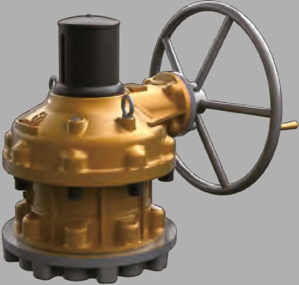
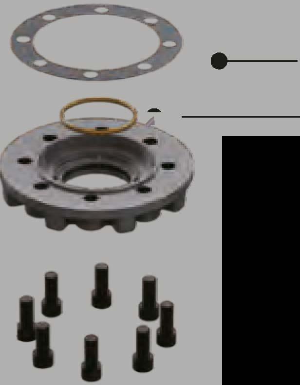
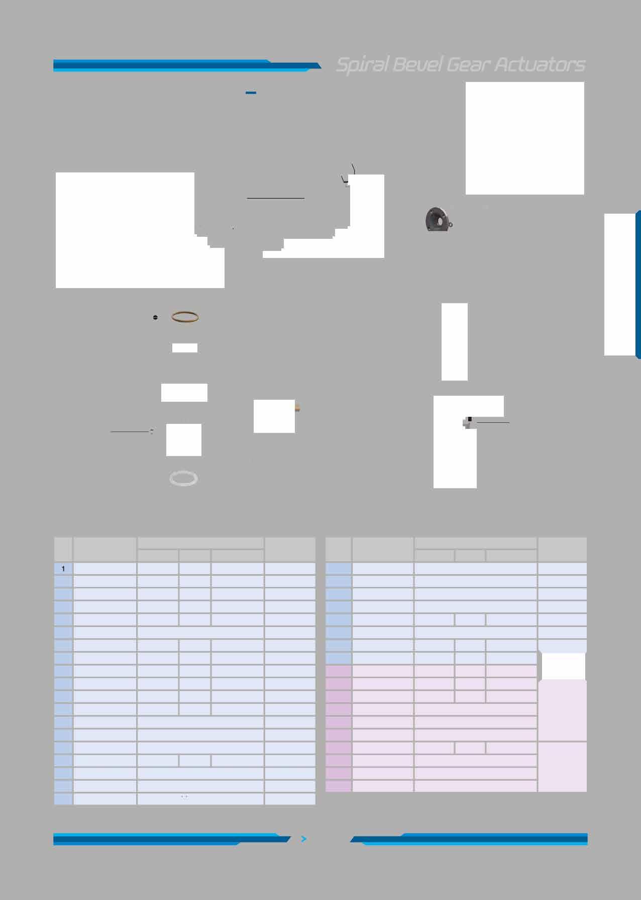
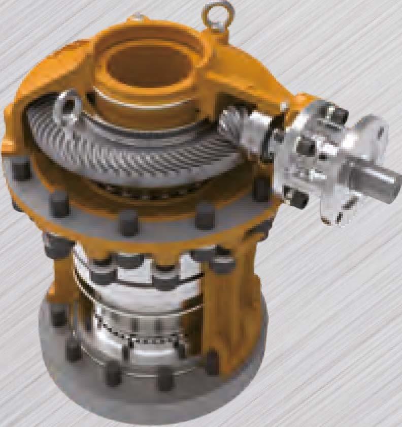
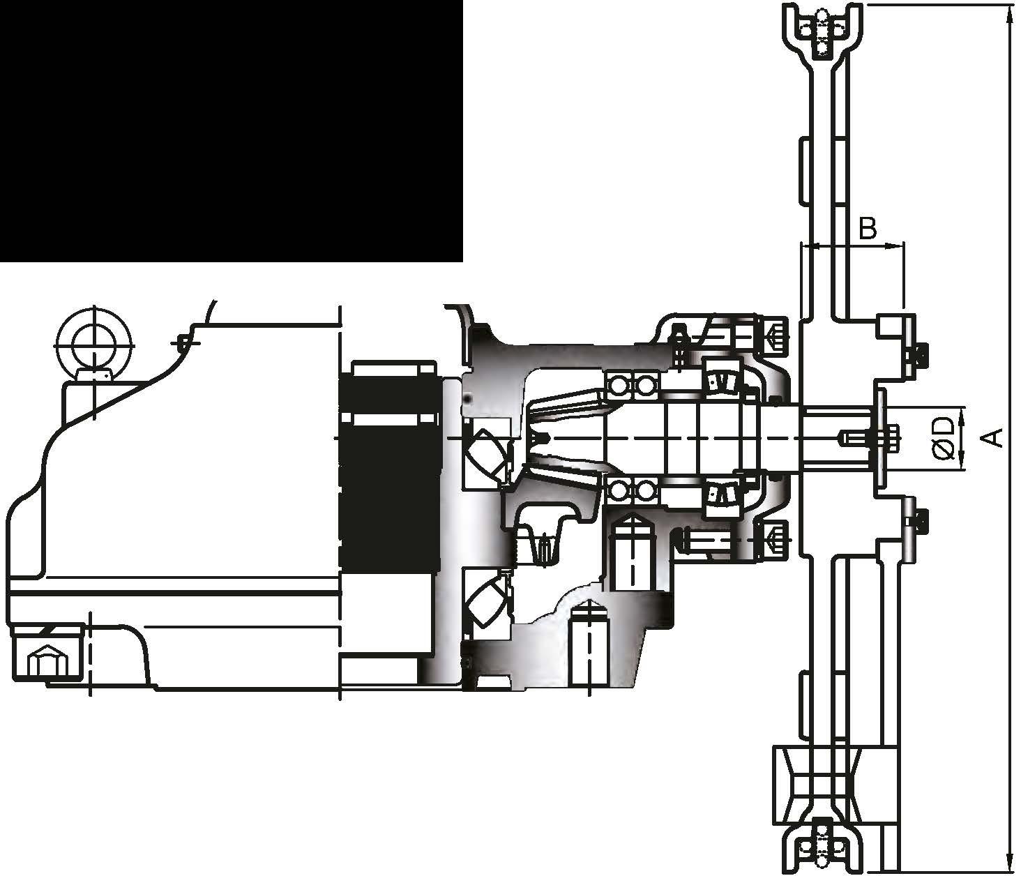
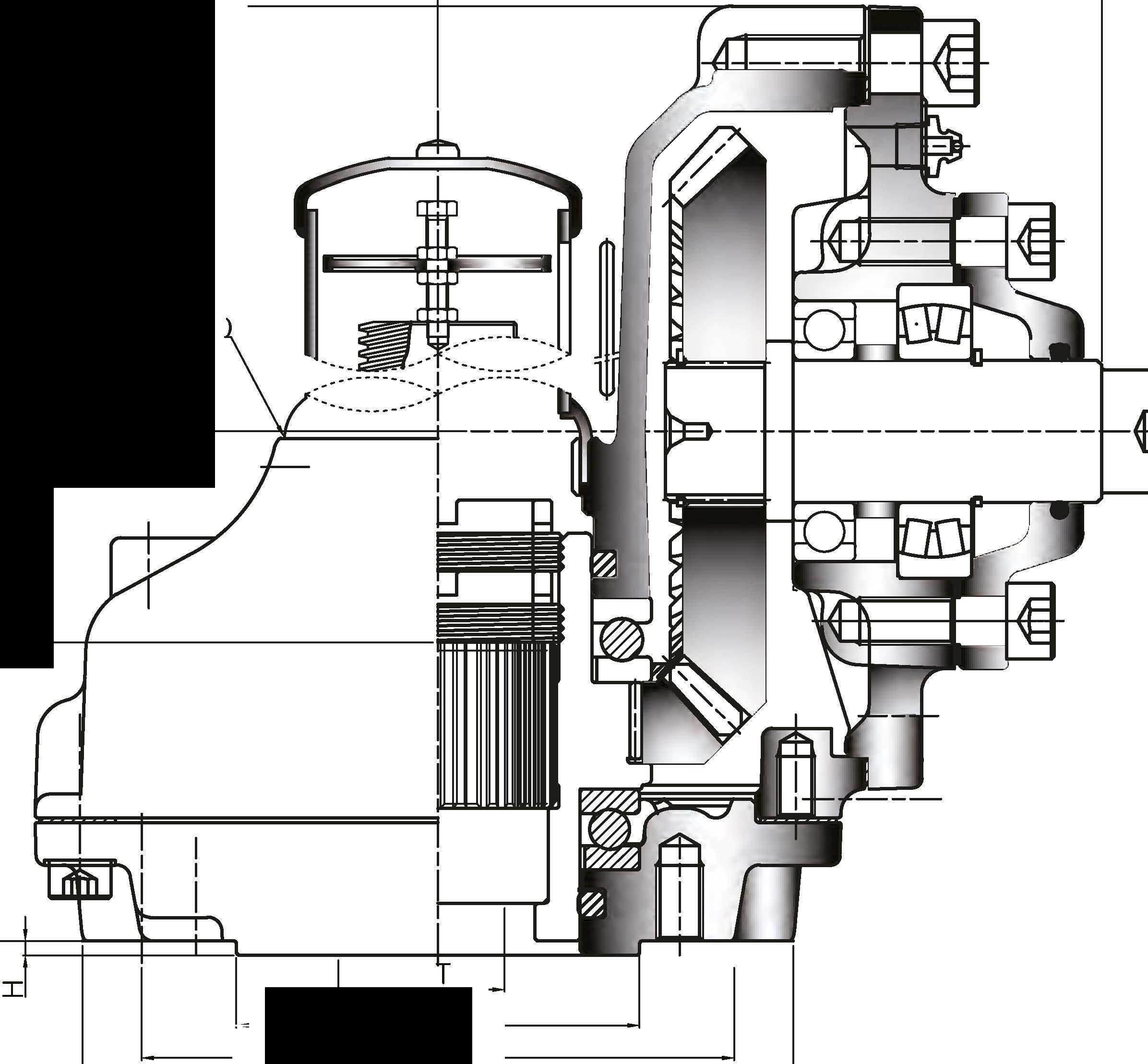
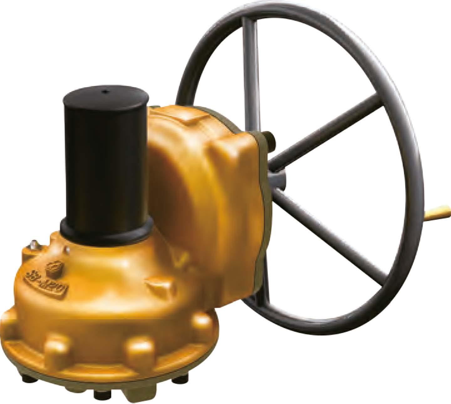
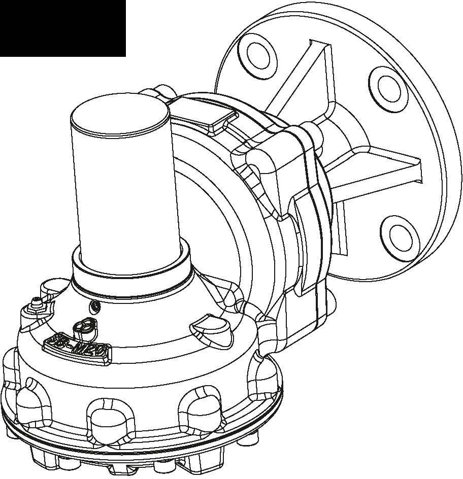
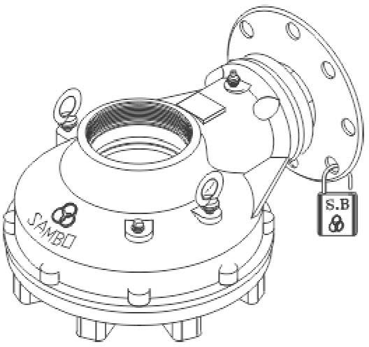
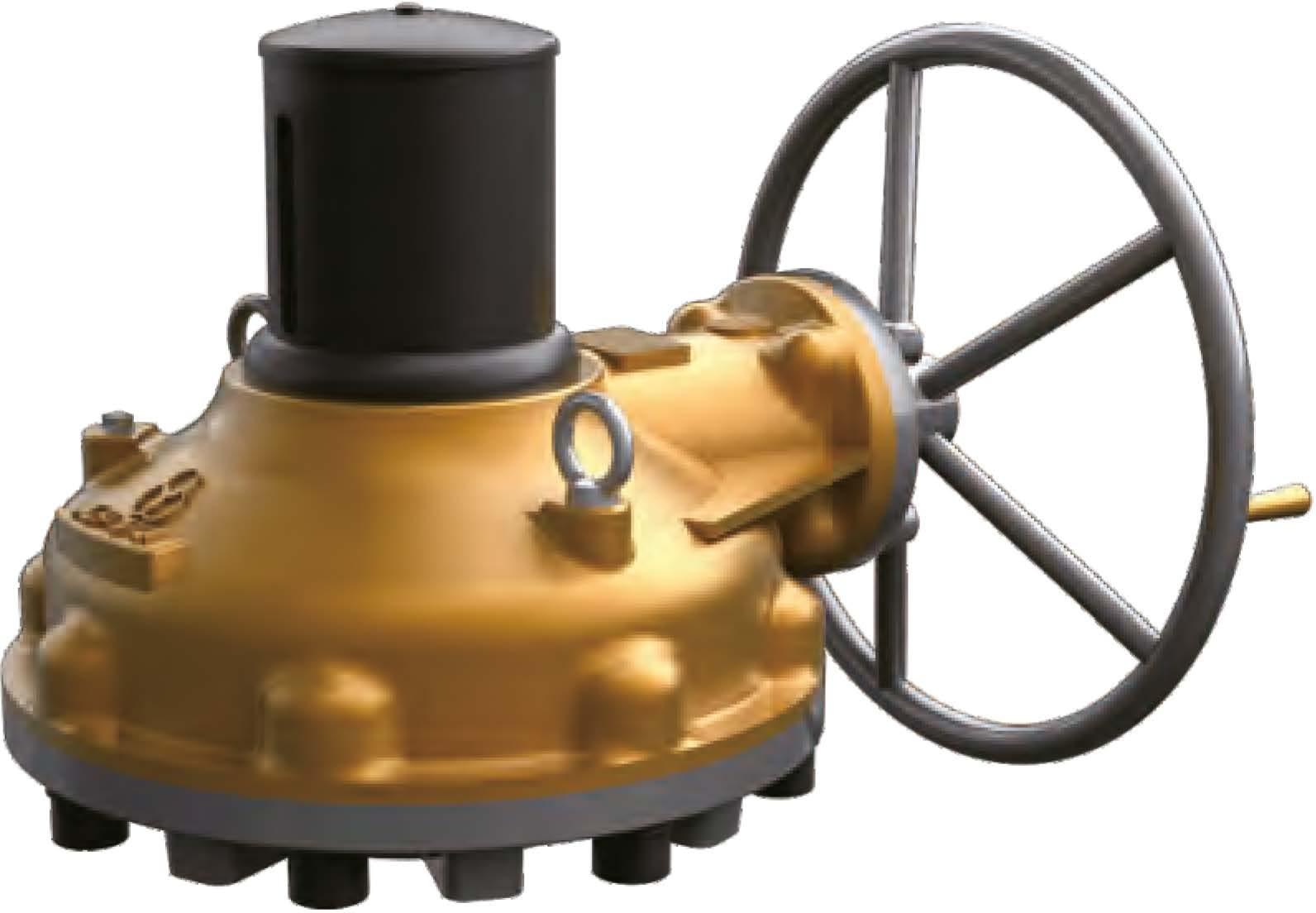
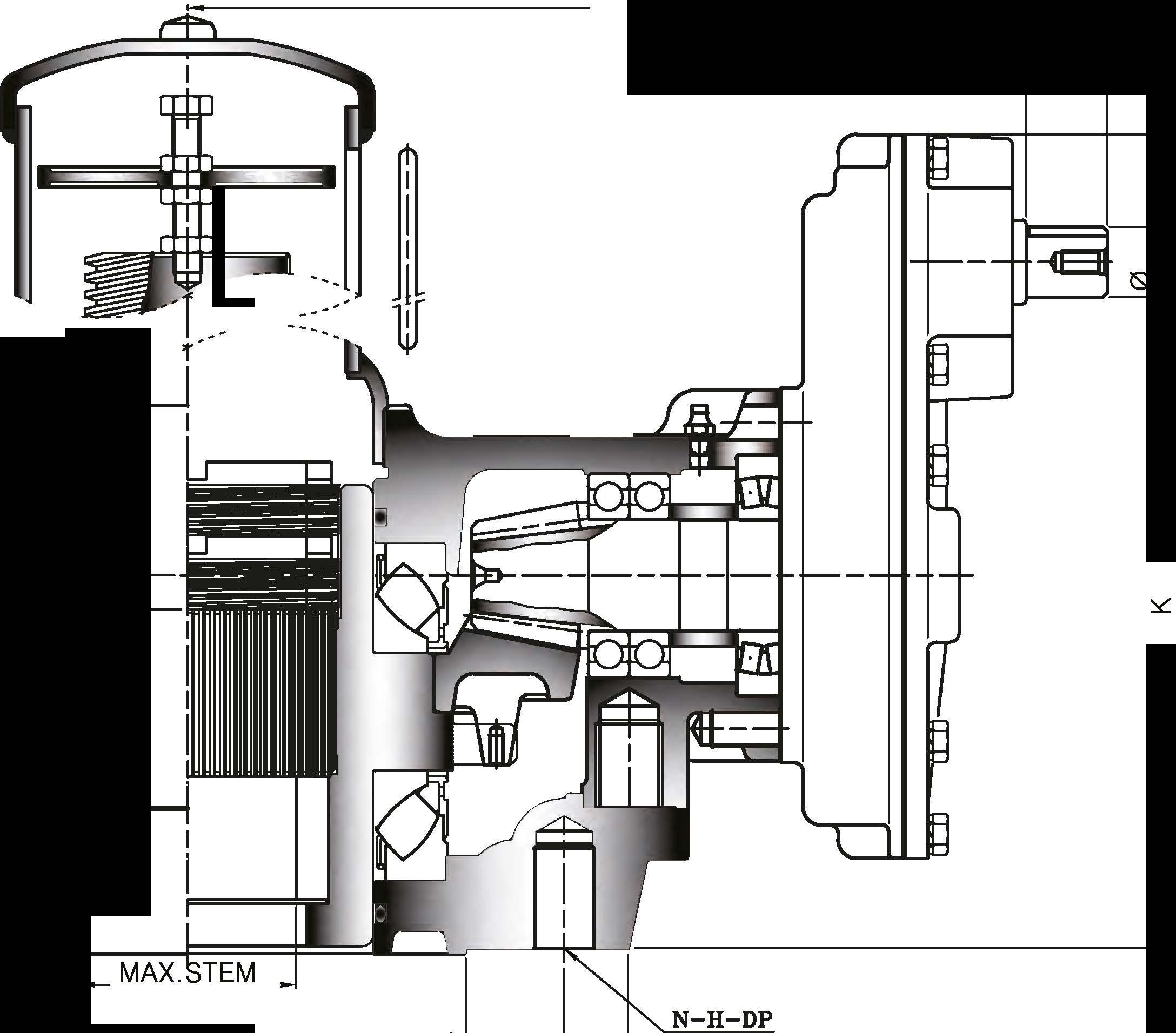
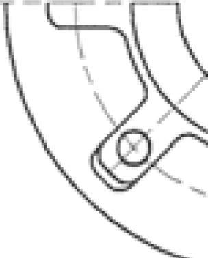
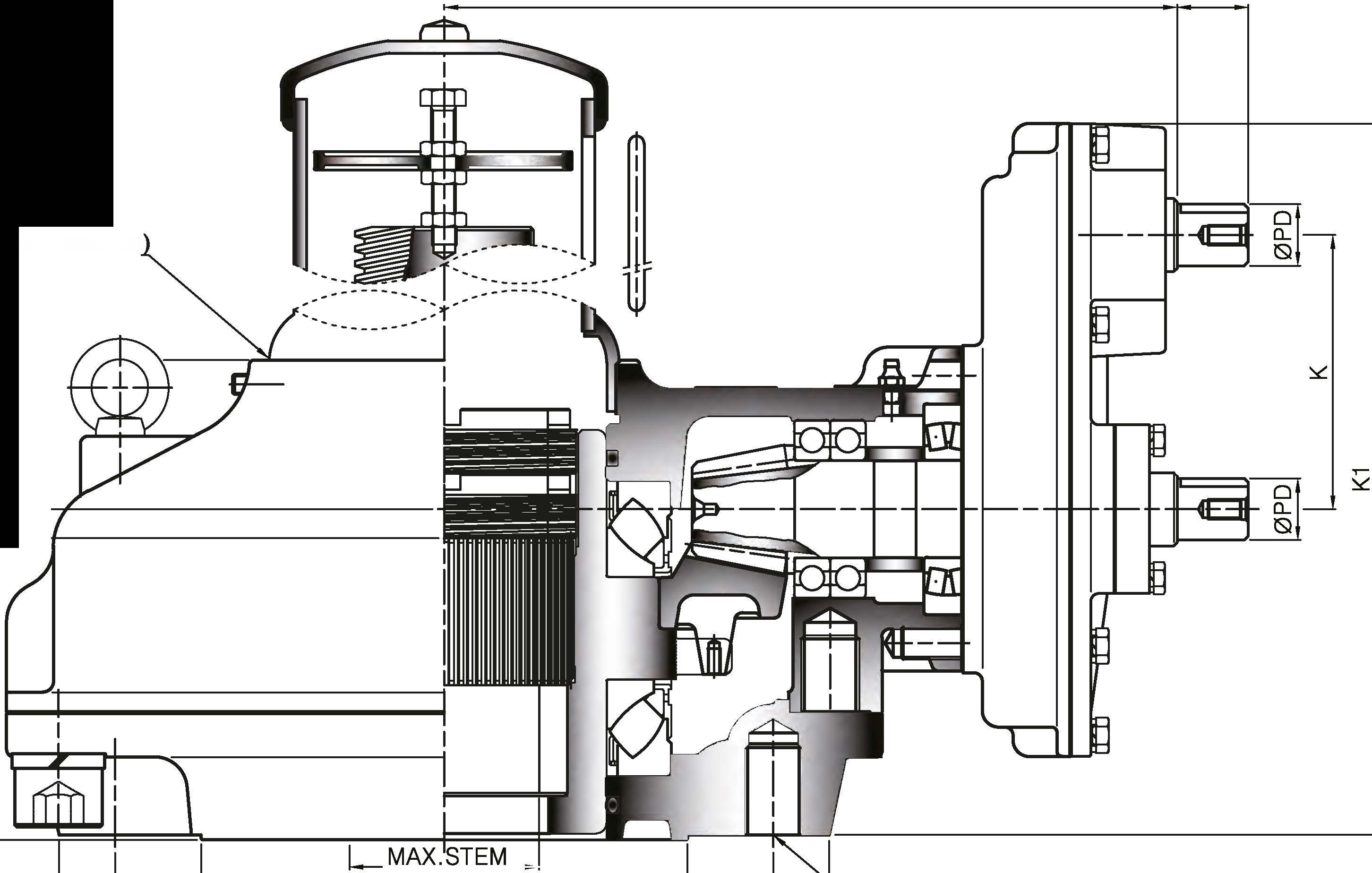
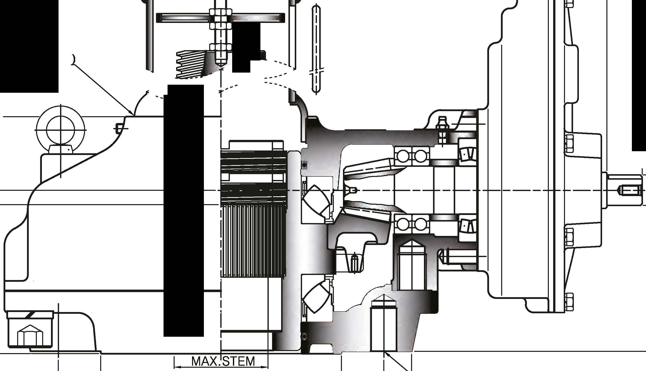
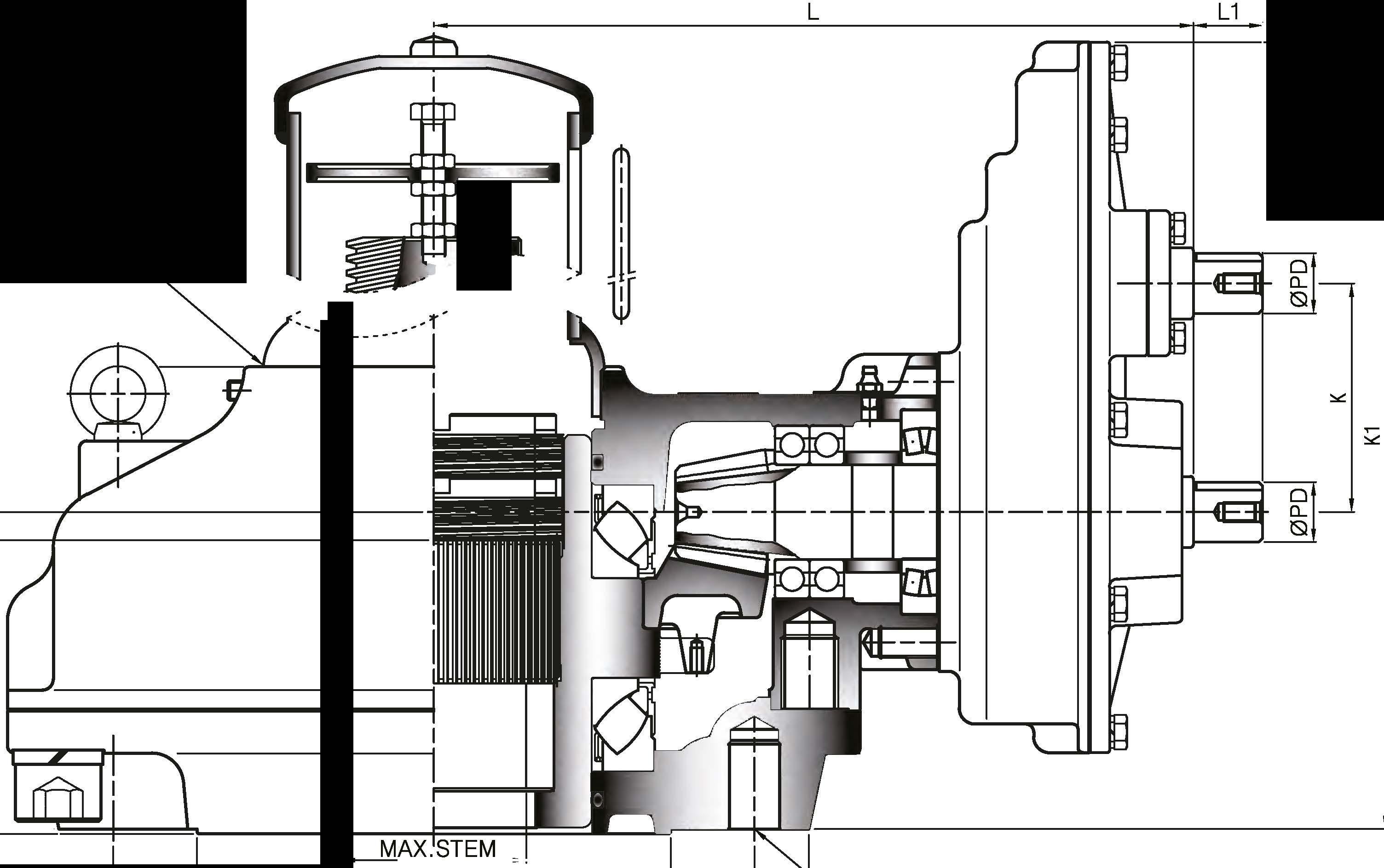
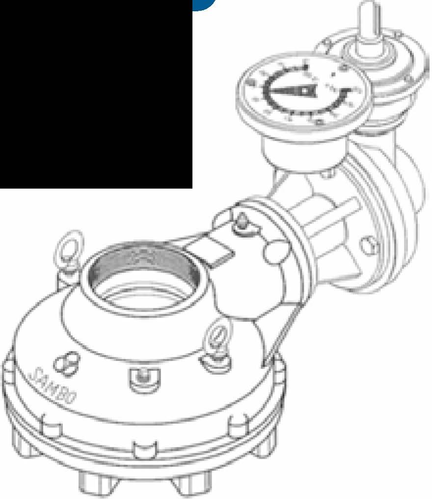
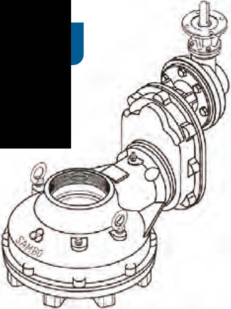
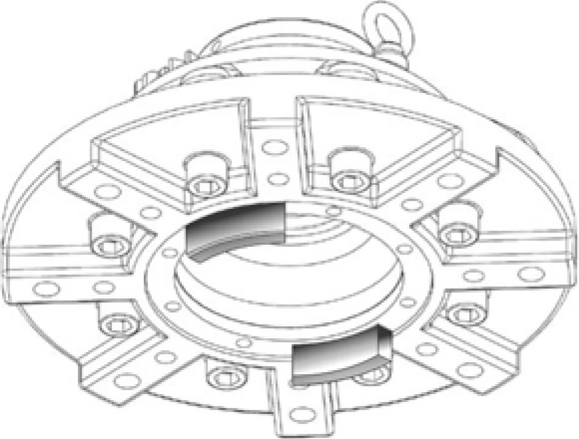
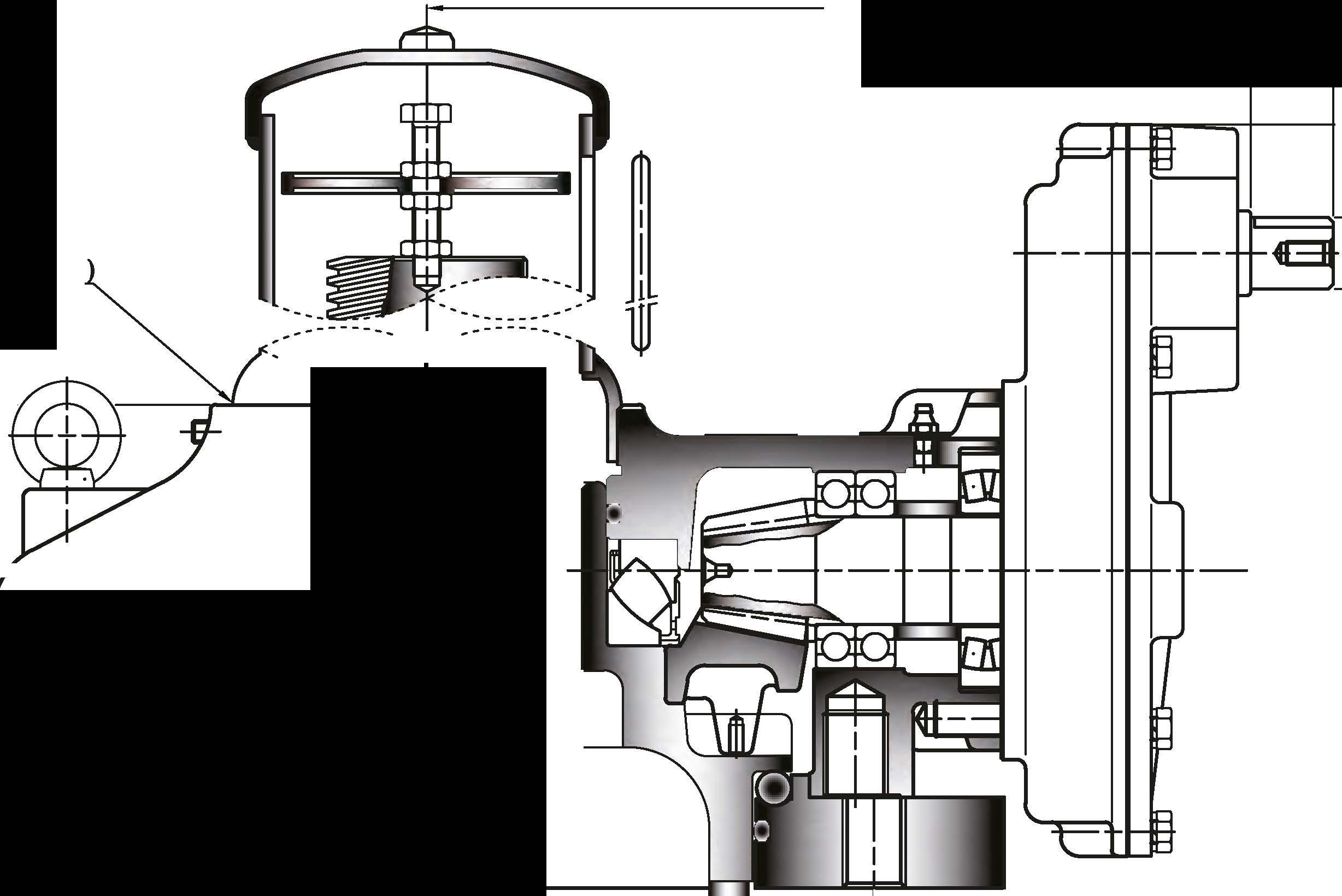
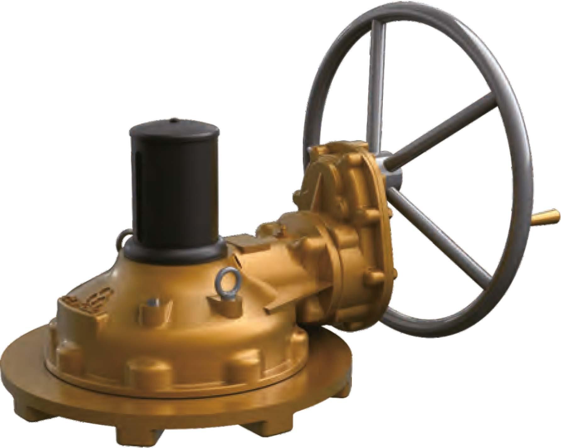
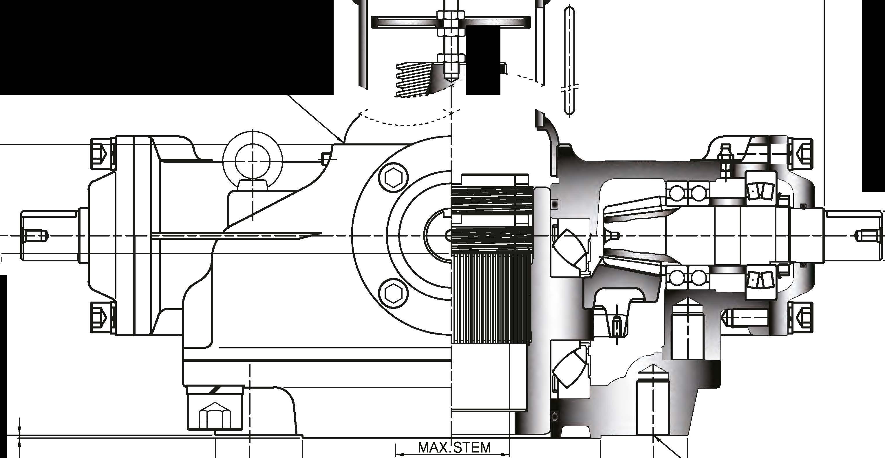
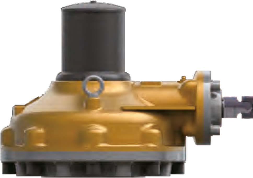
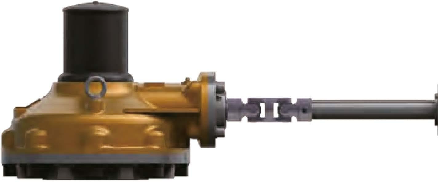
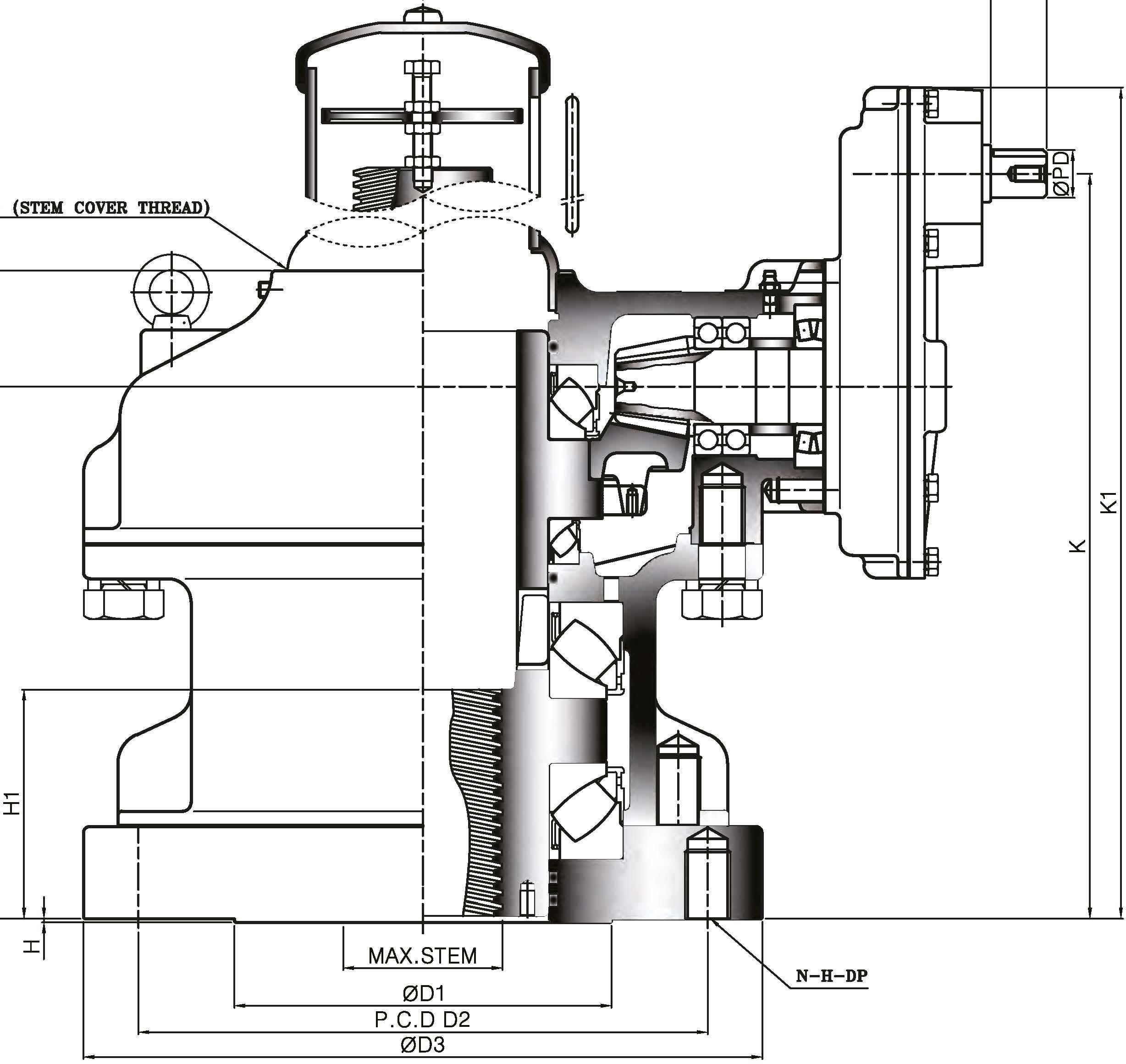
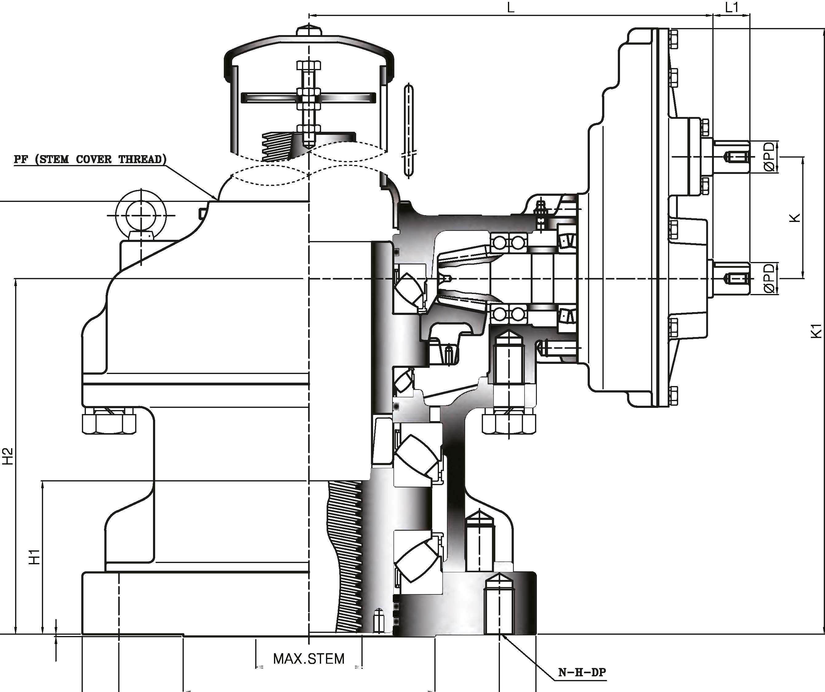
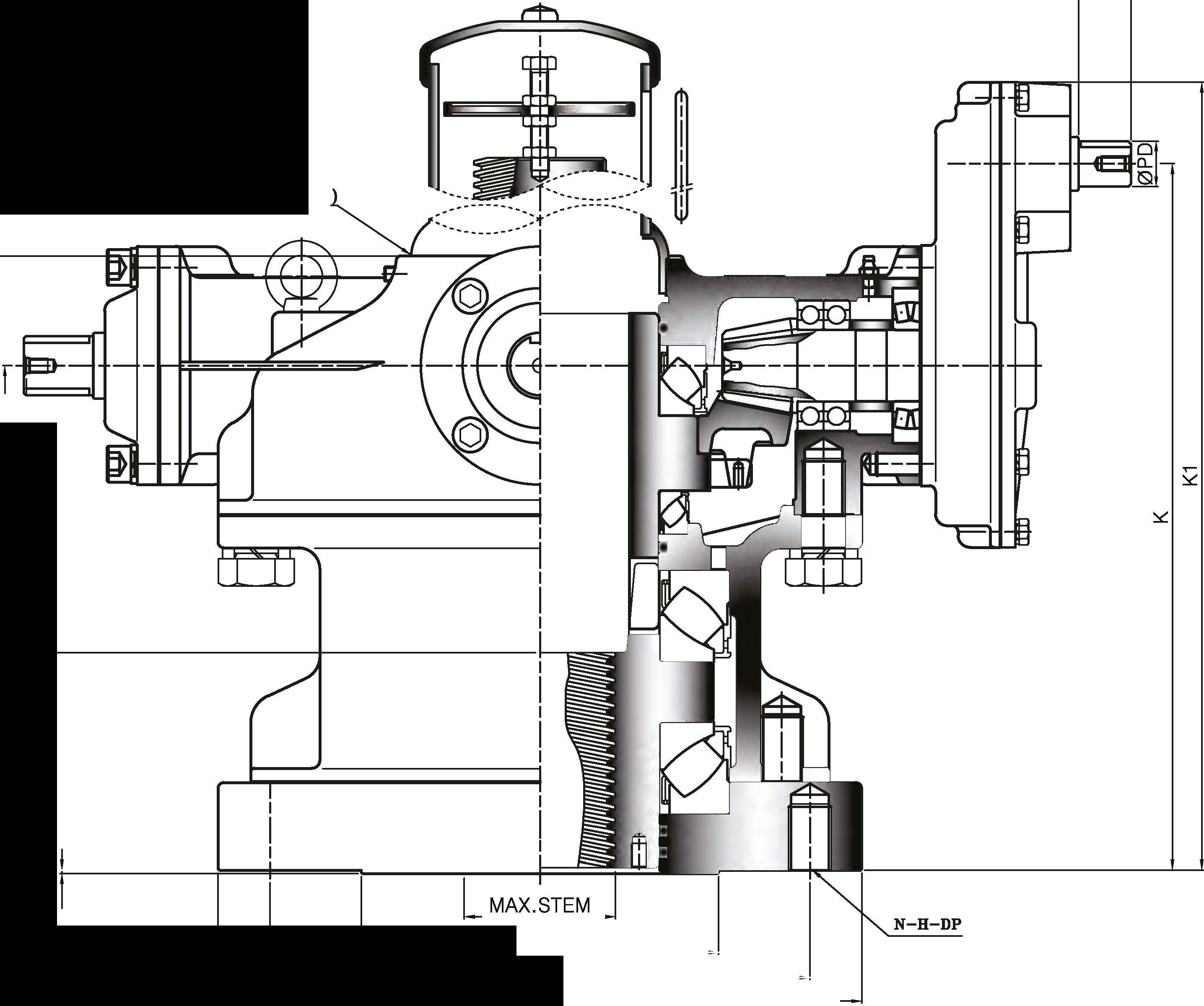
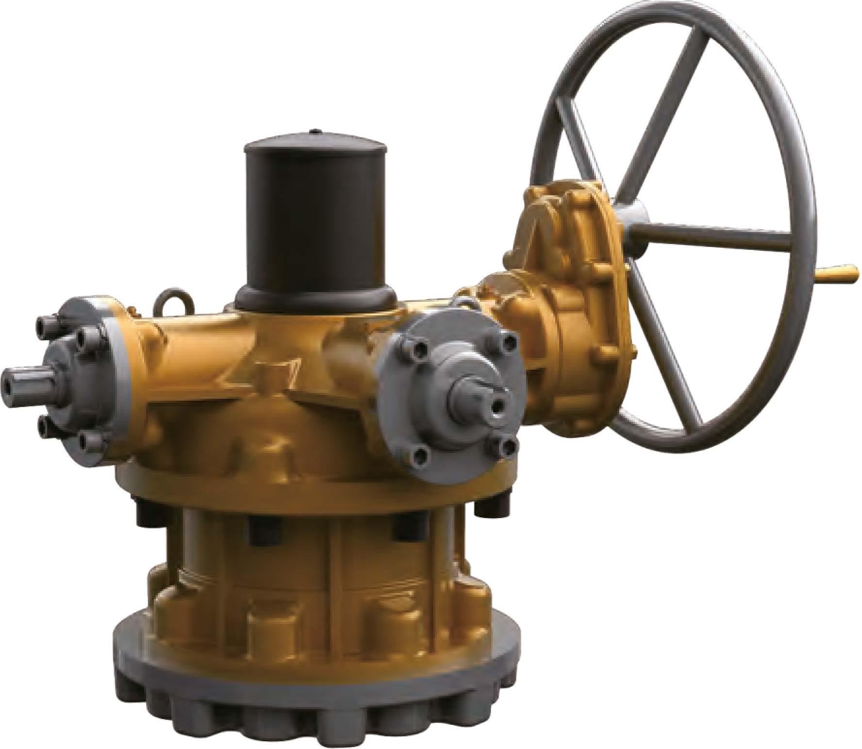
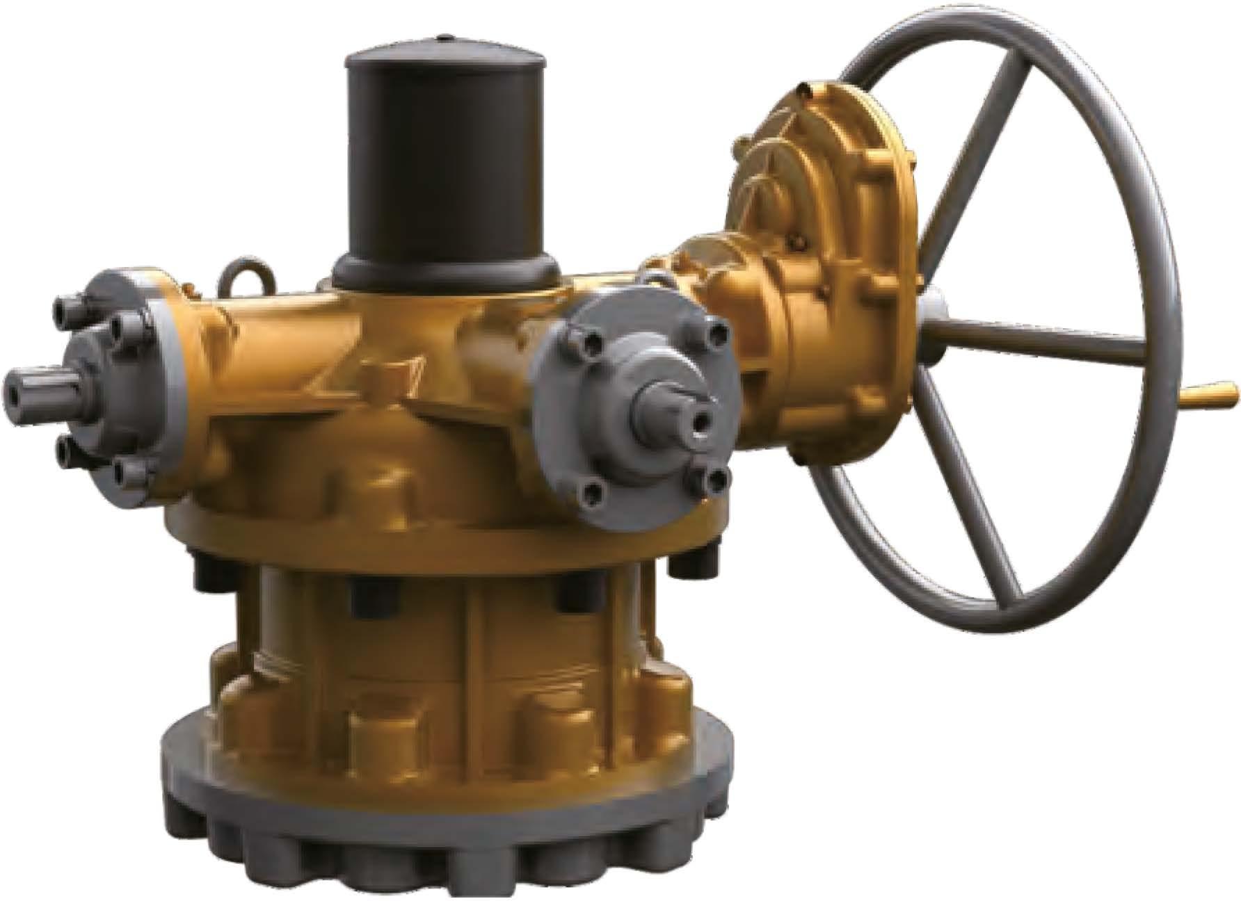
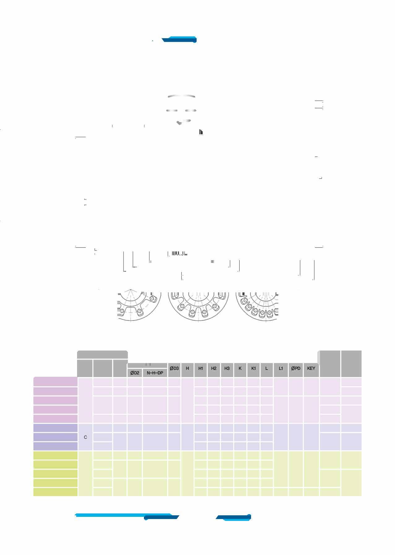
(!) Spiral Pinion and Spiral Bevel Gear
Pinion gear is 1045 heat treated steel. Bevel Gear is 1045 steel. Both gears are precision cut.
@ □-ring
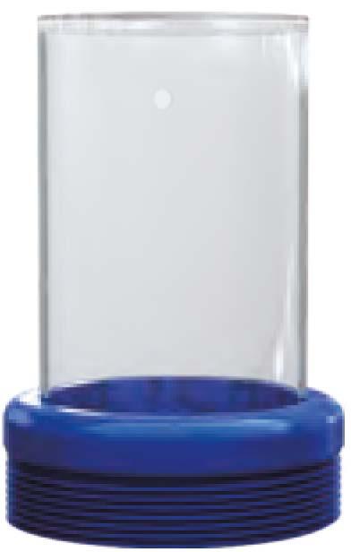
Units are completely □-ring sealed, suitable for temporary submergence to meet IP67 Class.
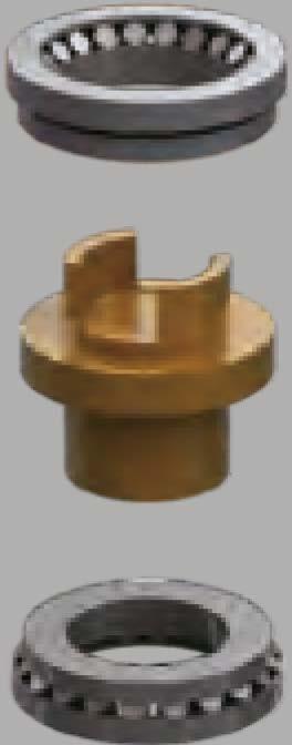
® Spherical Roller Bearing
This input Bevel pinion is fully supported on deep groove ball bearings to provide excellent radial support.
® Gaskets
The Base & end cap is sealed by a Non-asbestos Gasket to prevent any leakage and is waterproof.
® Thrust ball or Self-Aligning Thrust Roller Bearing
Provides anti-friction capacity and are high load type.

Each unit has a Alumite Grease type fitting and a grease plug for adding lubricant
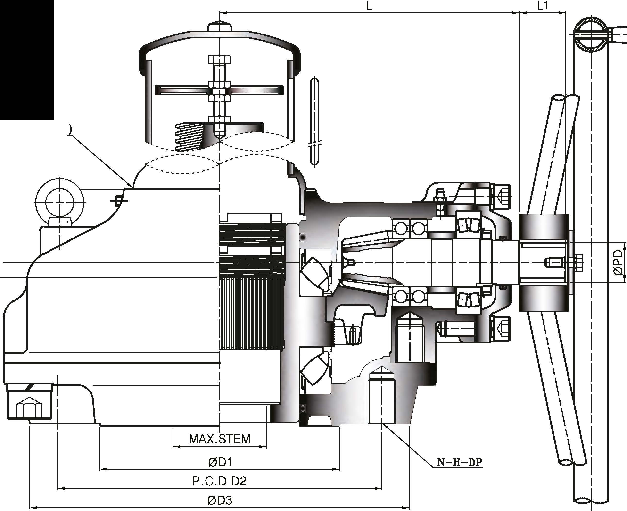
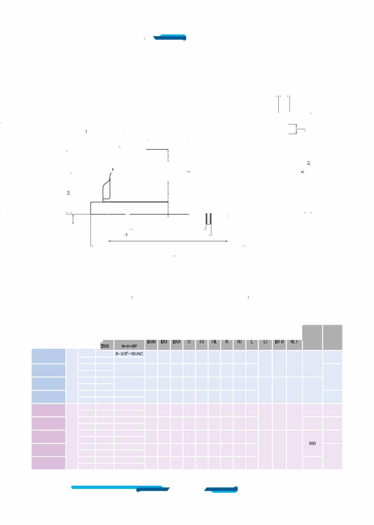
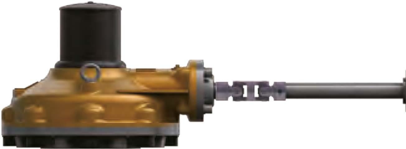
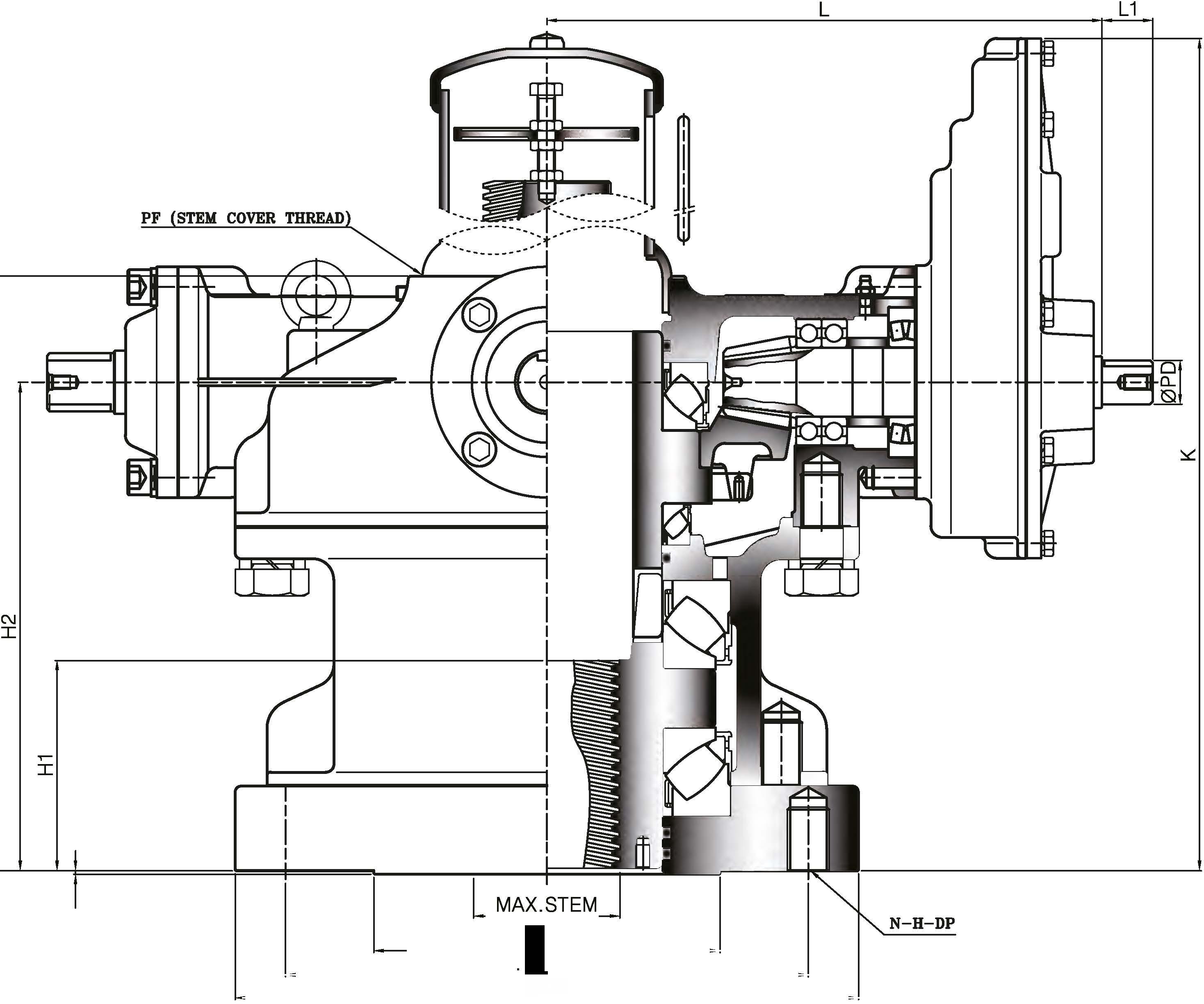
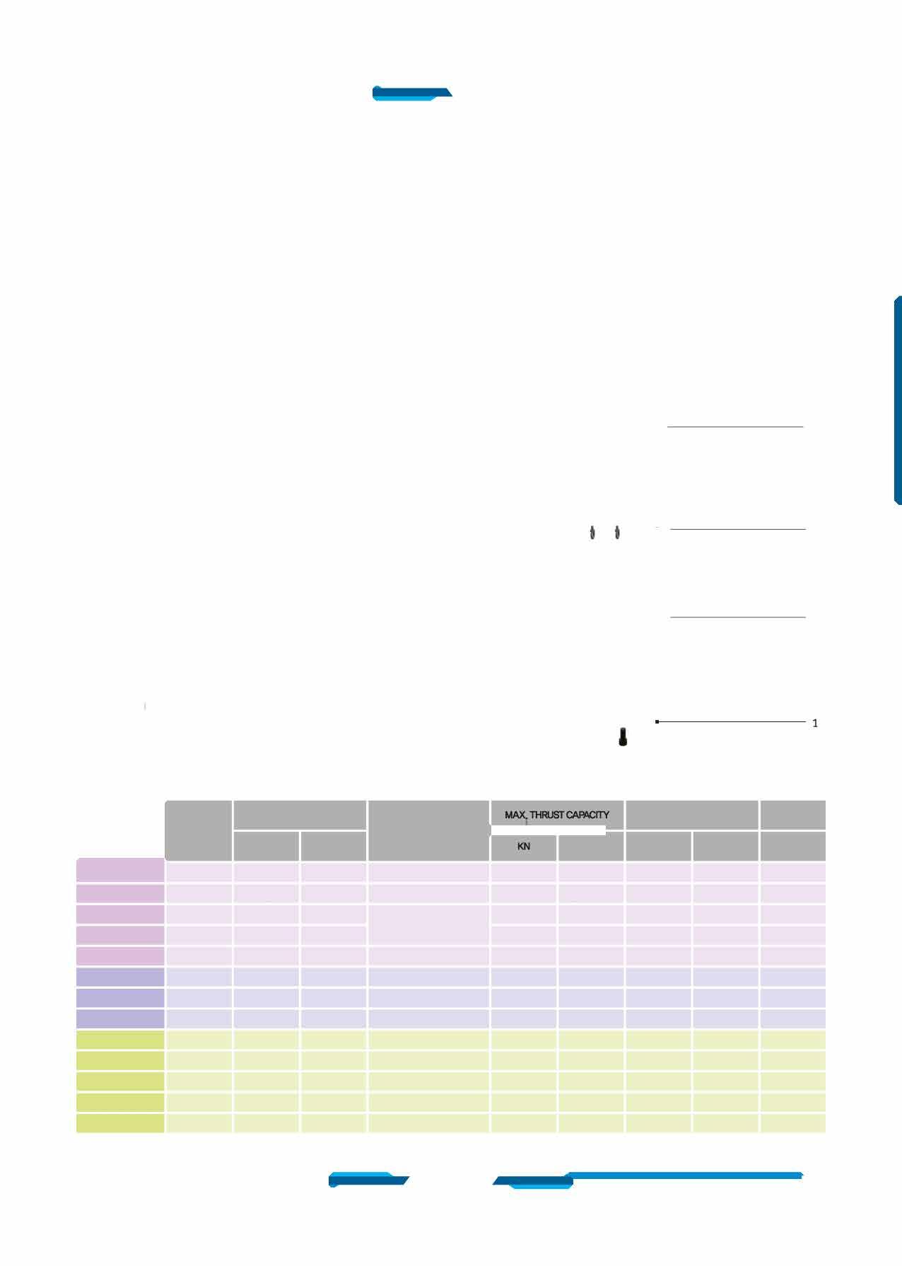
TheSB-VSeriesofSpiralBevelGearrangesupto75,DD□Nm (55,317ft-lbf}
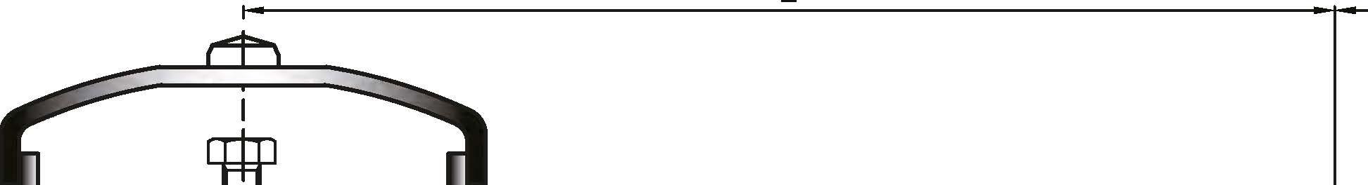
Stem capacities are up to 230mm (9.05inch).
Torque and Thrust capacities up to 7,3DDKN (2,585,300lbf}
A high Load design, type SB-VH is also available ranging up to 142,DD□Nm (1□4,734ft-lbf).
Thrust capacities up to 11,SDDKN (2,585,30Dlbf) stem capacities are up to 270mm (10.53inch).

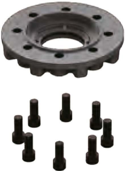
® Dual Locking Nuts
This design incorporates dual locking nuts which provide a jam Effect for positive locking. No set screw or pinning is required.
(Z) Stem Nut
A unique top Entry Replaceable stem Nut.
After long years of service can be easily replaced without removing Gear from value.
IYlaterial is high tensile brass providing both corrosion and abrasion resistance.
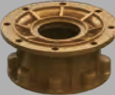
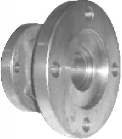
@ Drive Sleeve
Also Ductile Iron, Class 55-45-12. supports both axial and radial loads.
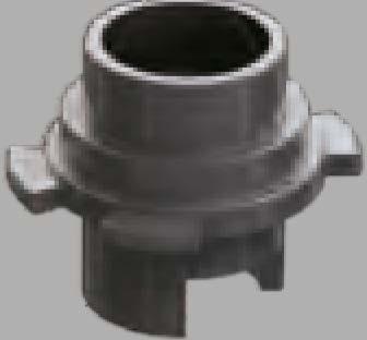
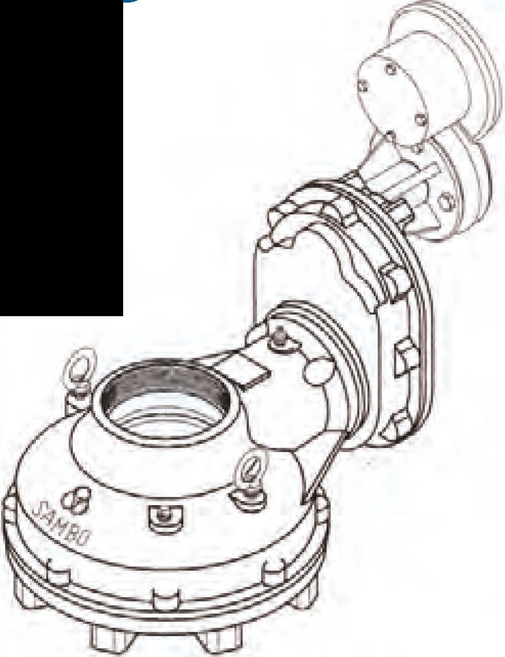
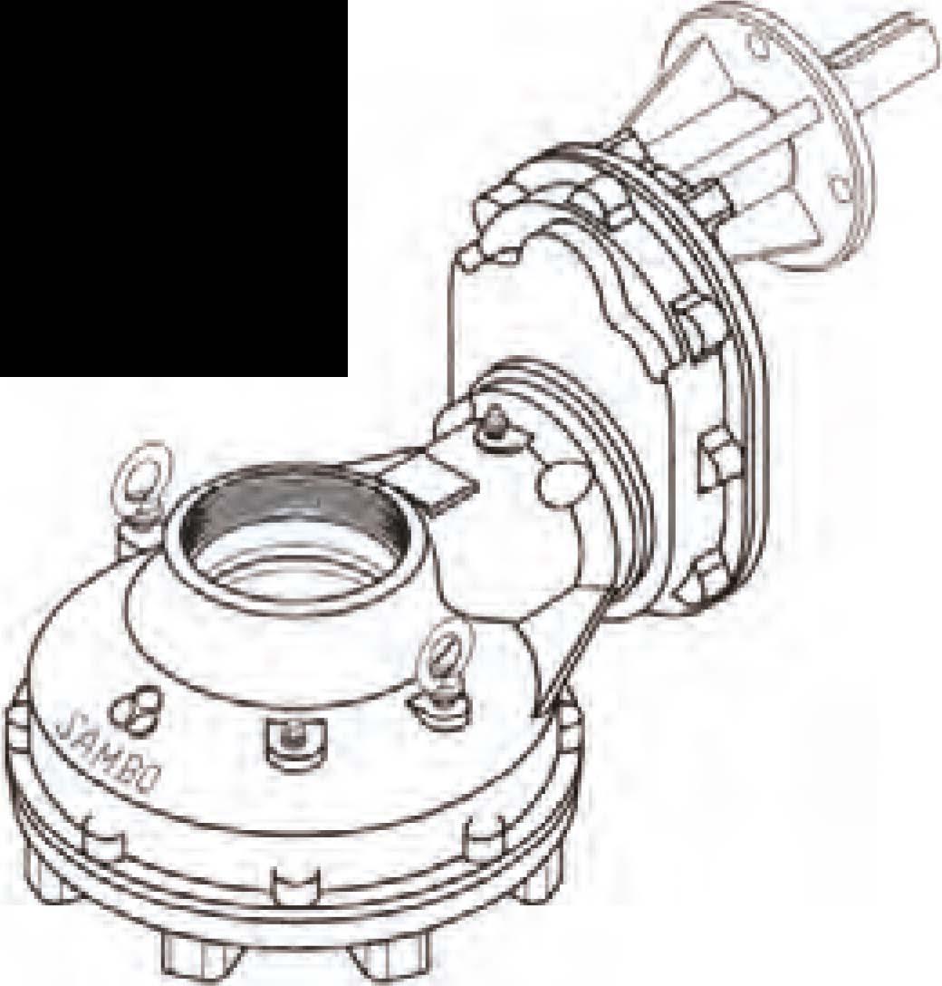
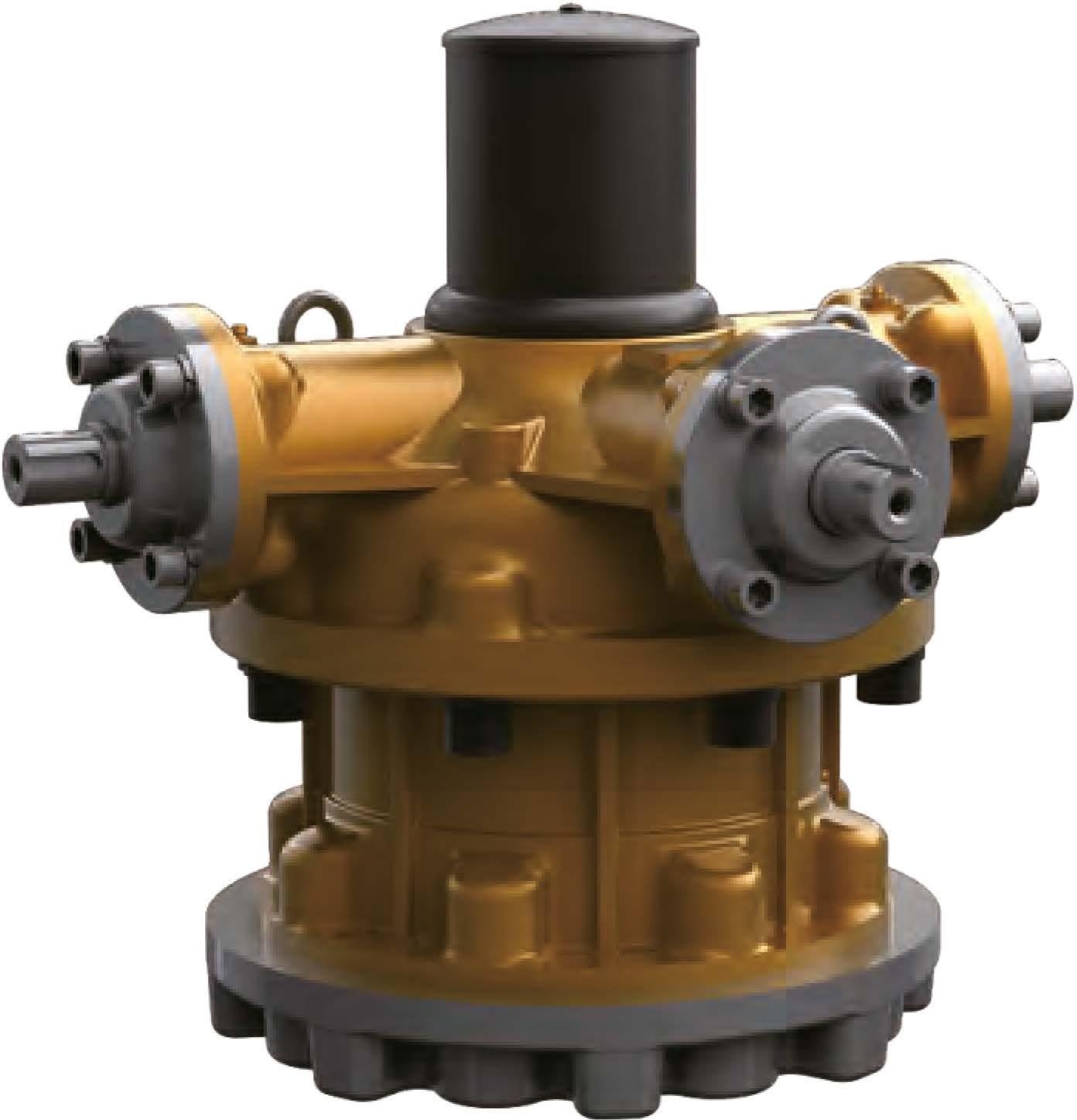
® Housing and Base
All external castings are Ductile Iron. Class 55-45-12, Tensile Strength of 55,DDD psi This provides high strength and excellent impact resistance.


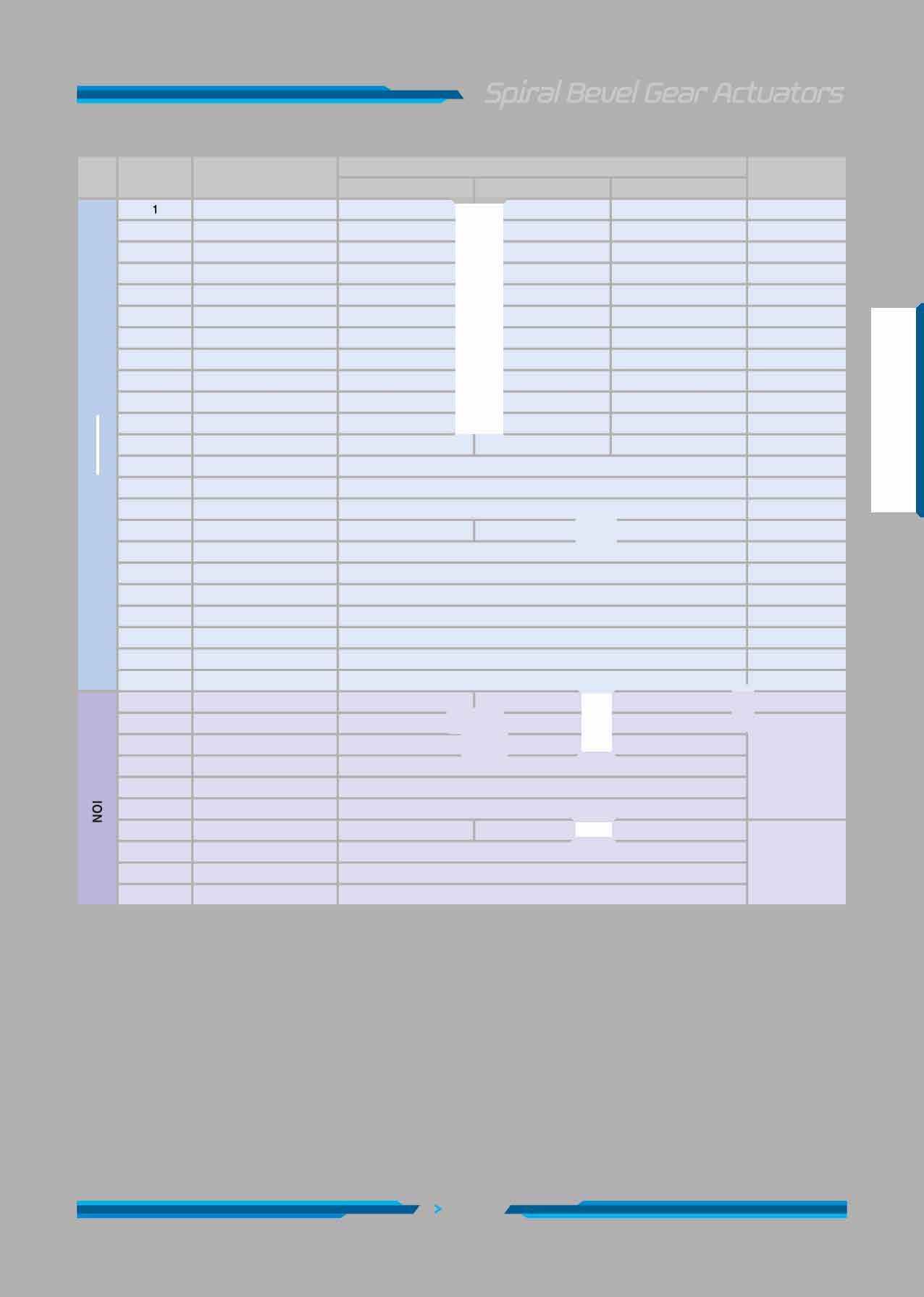
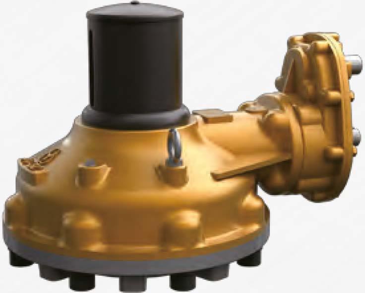
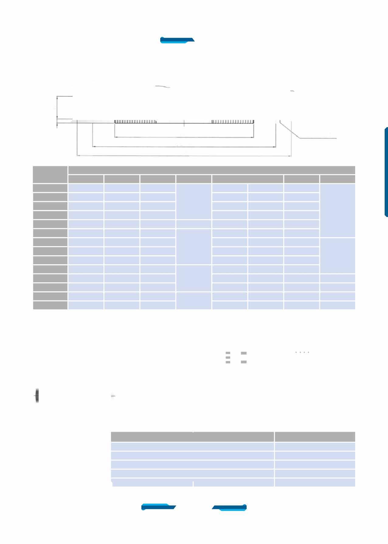
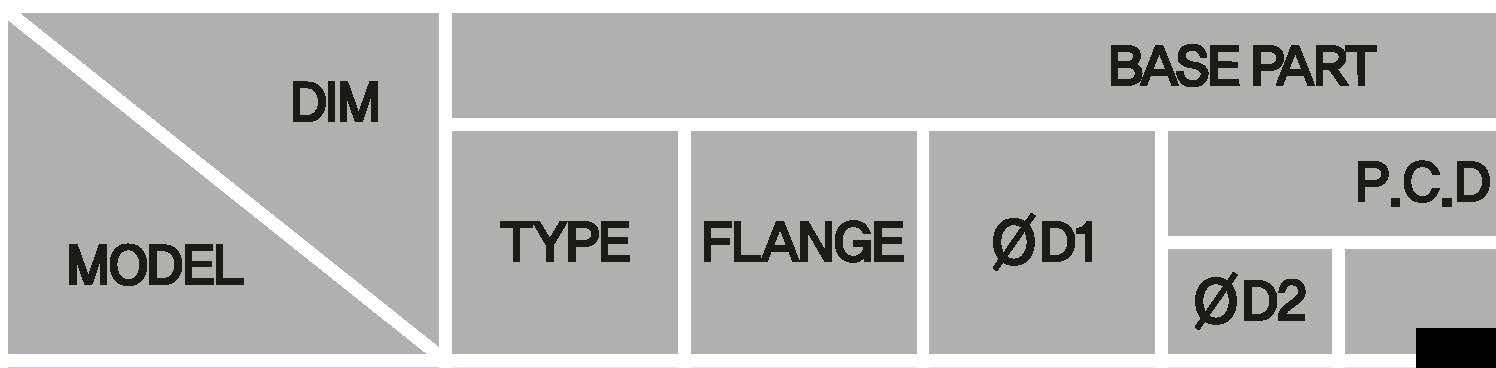
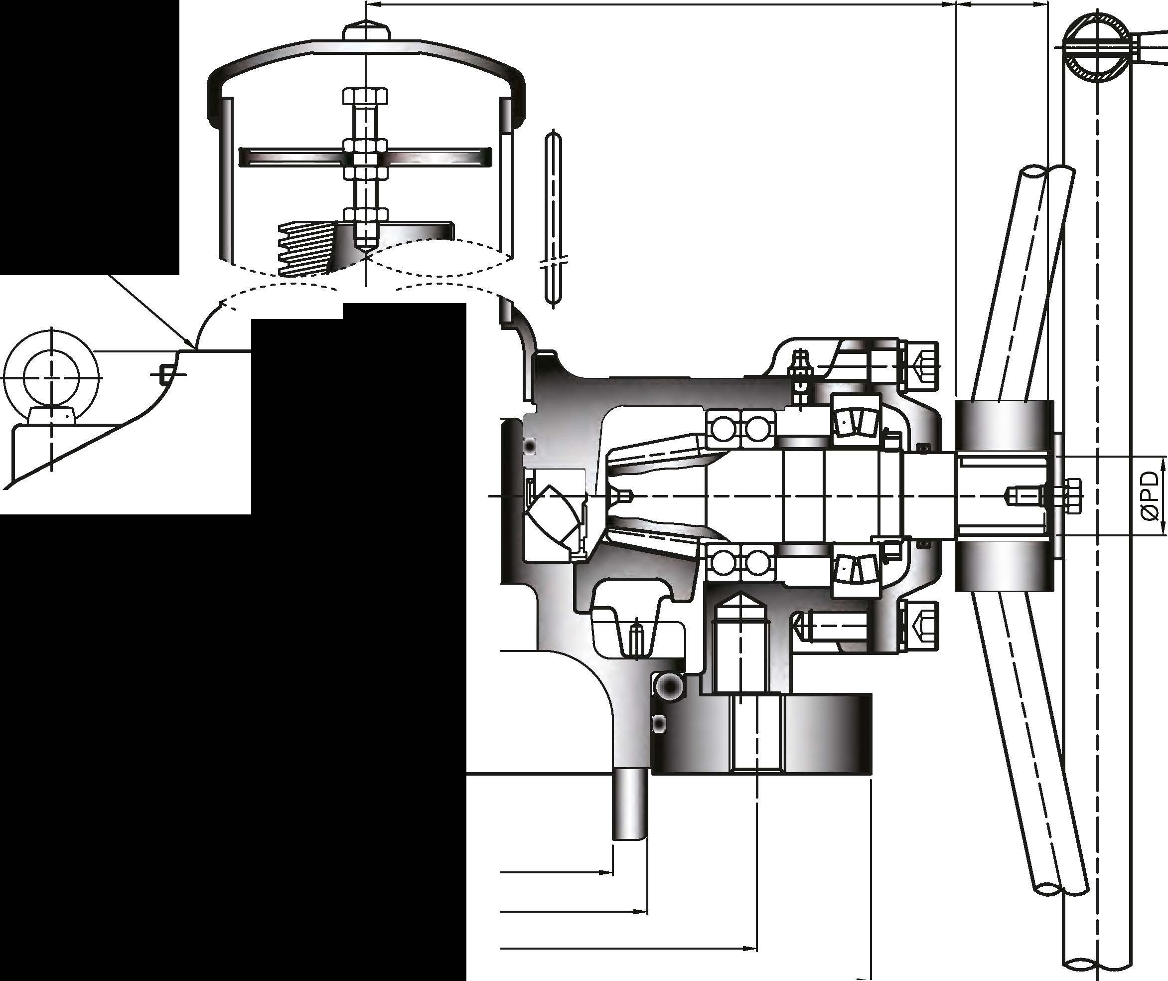
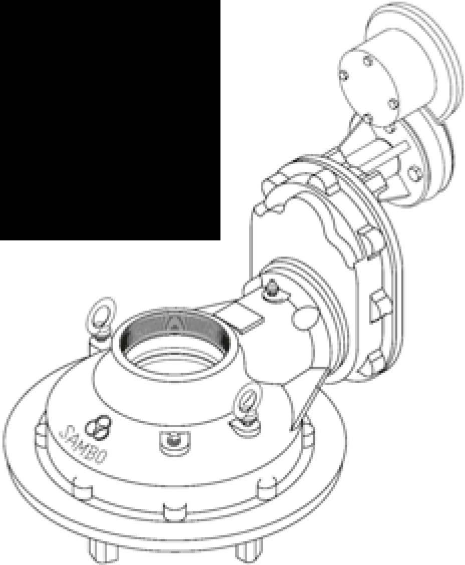
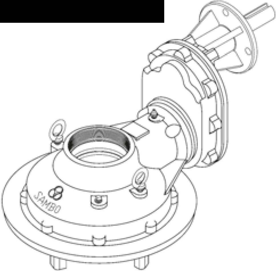
DESCRIPTION
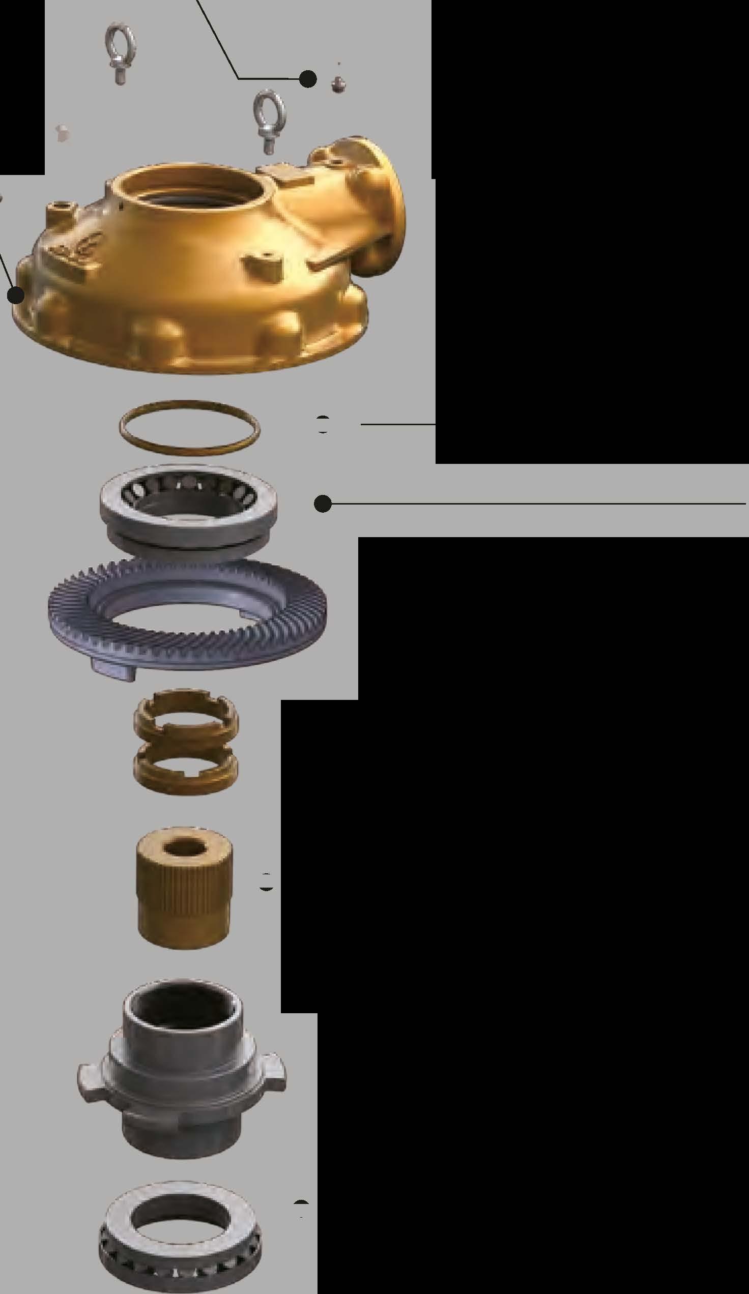
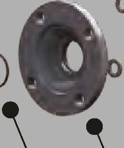
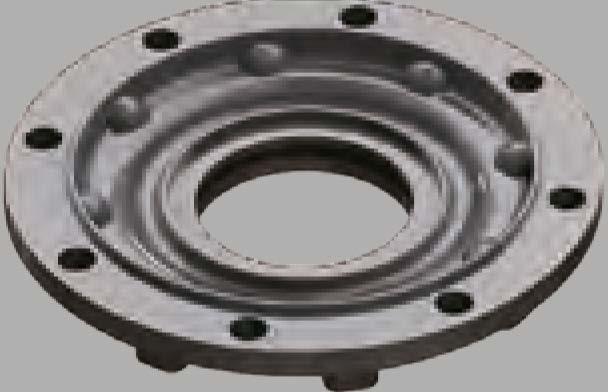
Housing
Base
SpiralBevelGear
SpiralPinion
DriveSleeve
DualLockNuts
EndCap
WrenchBolt(S/W)
WrenchBolt(S/W)
RadialBallBearing

SphericalRollerBearing
ThrustBearing
GreasePlug
O-Ring
O-Ring
Collar
Bearing Washer
BearingNut
GreaseFitting
SetScrew
EndCapGasket
BaseGasket
EyeBolt
OP-01. OP-02. OP-03. OP-04. OP-05. OP-06. OP-07. OP-08. OP-09.
OP-10.
StemNut
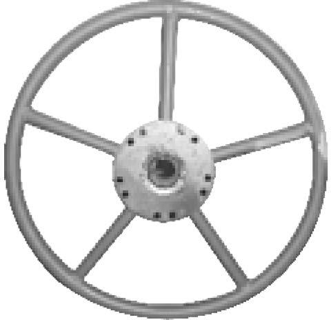
HandWheel
Key
NamePlate
Washer
HEX.Bolt(S/W)
StemCover
IndicateBolt
HEX.Nut
Indicator
MATERIAL
NAME
DuctileIron
DuctileIron
CarbonSteel
CarbonSteel
DuctileIron
CarbonSteel
DuctileIron
AlloySteel
AlloySteel
SpecialSteel
SpecialSteel
SpecialSteel

Steel+Galvanizing
Silicon
Silicon
SteelPipe
Steel
Steel
Steel+Galvanizing
StainlessSteel
Non-Asbestos
Non-Asbestos
Steel+Galvanizing
Bronze
SteelPipe �
CarbonSteel r
StainlessSteel
StainlessSteel
StainlessSteel
SteelPipe
Steel+Galvanizing
Steel+Galvanizing
Plastic
A536-65-45-12
A536-65-45-12
A576-1045
A576-1045
A536-65-45-12
A576-1045
A536-65-45-12
A322-4135
A322-4135
A295-52100
A295-52100
A295-52100 SGP ==i


1 All castings are Ductile Iron, FCD-450 (ASTIYl Class 65-45-12)
2. In case of option for special request, it can be worked Nickel coating, high tensile stainless.
3. Also, the material can be changed as ALBC3(Aluminium Bronze), steel(A576-1□45), A439 Gr □2C (Austenitic ductile iron casting), etc.
4. □-Ring Seal & Lubricant: Standard is Silicon & Buna "N", temperature range -20· C to +120° C (-4° F to +248° F).
Standard lubricant is Zenith EPSB 2, temperature Range -20' C to +200' C (-4' F to +392' F). Other option are: High Temperature Viton □-Ring Grade V75, Temperature Range -30° C to +200° C (-22· F to +392° Fl Lubricant - Zenith SYN WS2 Temperature Range -30° C-400° C (-13° F-752° F) Low Temperature Silicon □-ring, Temperature Range -6□° C to +150' C (-76' F to +302' F) Lubricant - Zenith SBLT60□, Temperature Range -60' C-120' C (-76' F-248° Fl
5. SAIYIBD offers a wide variety of Handwheels, Chainwheels, Input Shaft, Locking Devices, etc.
6. SAIYIBD offers a wide variety of stem cover, stainless steel, polycarbonate. Paint: Unless specified, units are supplied with vp134 Red epoxy primer. SAIYlBD can provide finish coating upon request Size and component specitication in this catalogue are subject to change without prior notice for quality improvement • IYlarl< has been changed and updated.
»


Bronze
Steel
Carbon
StainlessSteel
StainlessSteel
Steel
Steel
Steel
Plastic

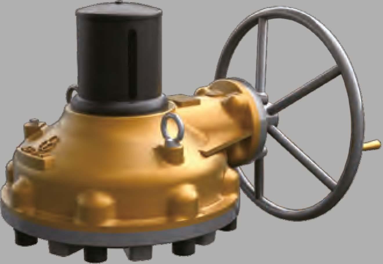
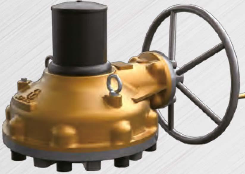
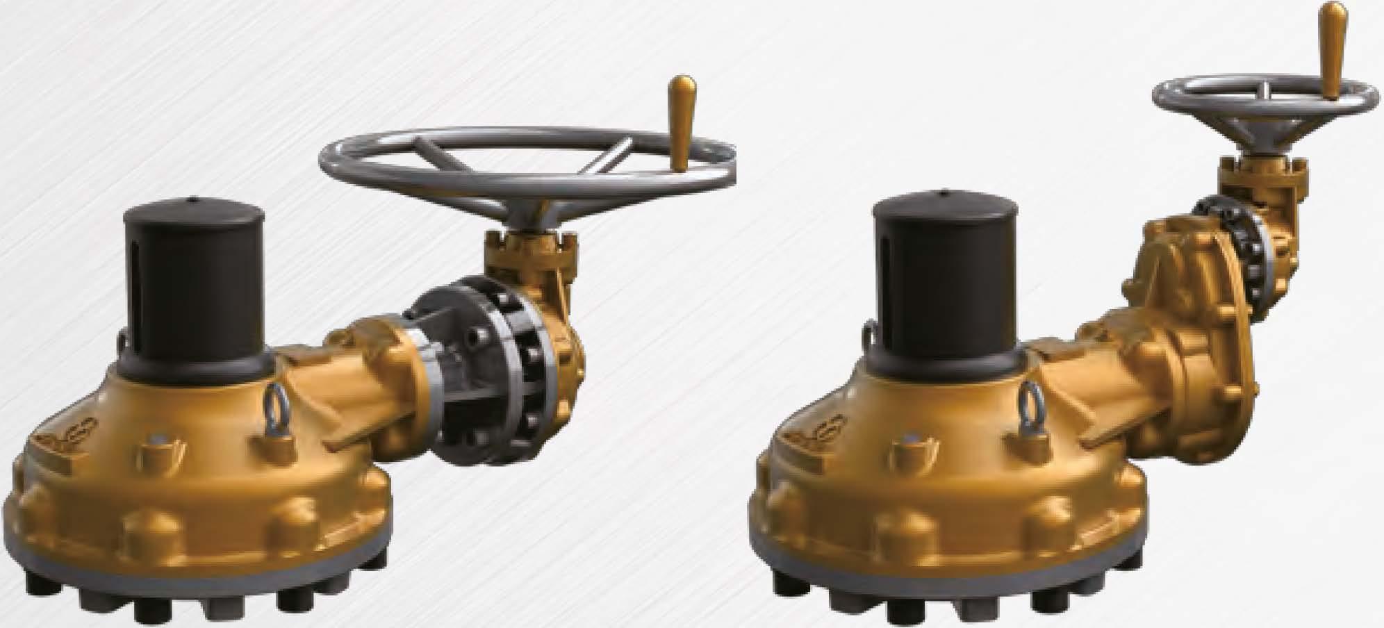
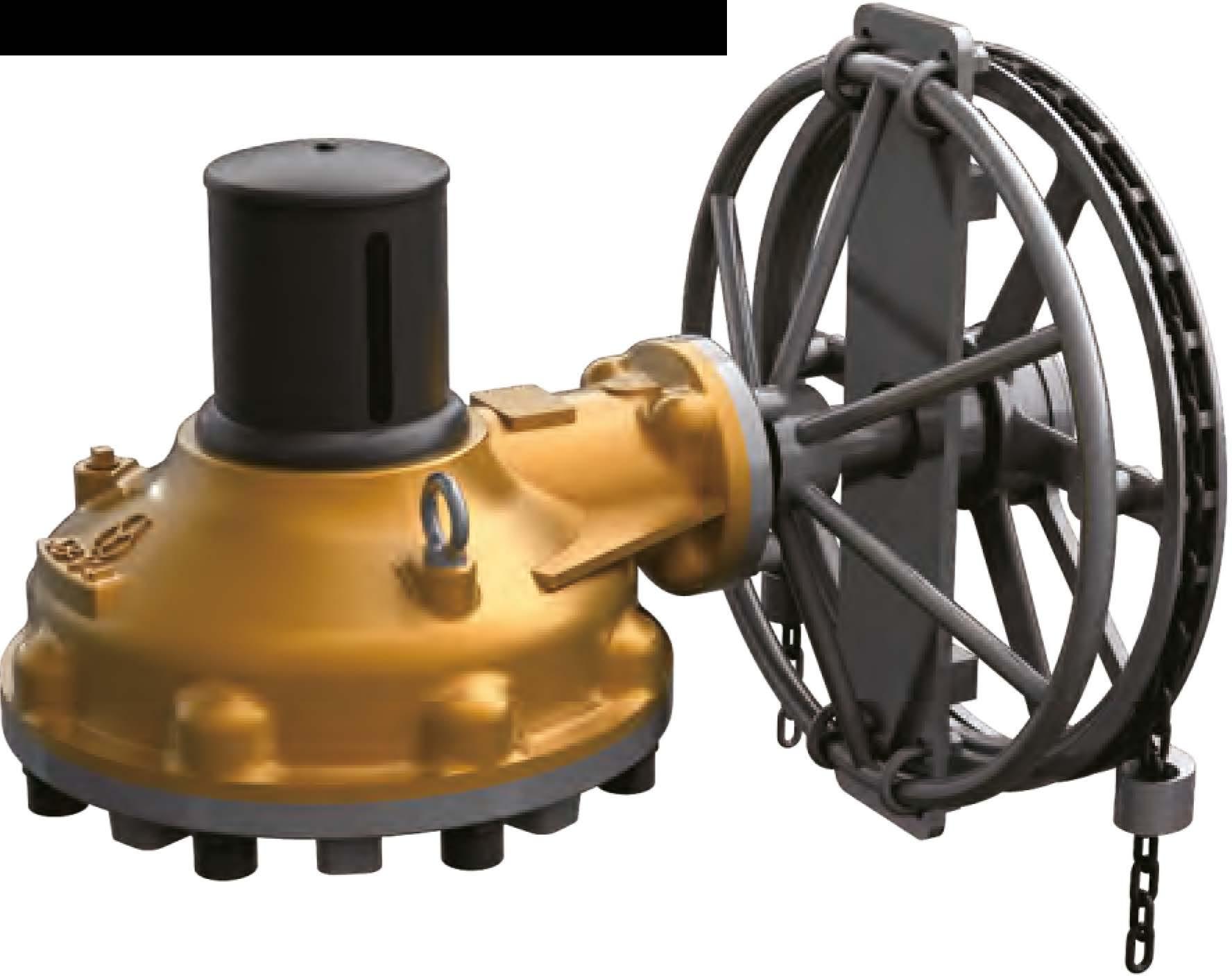
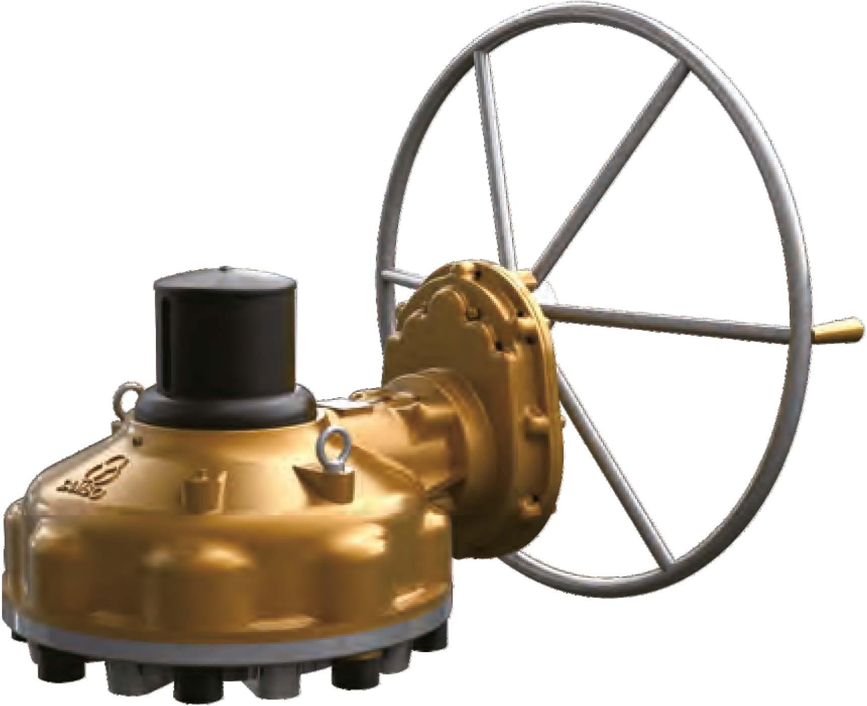
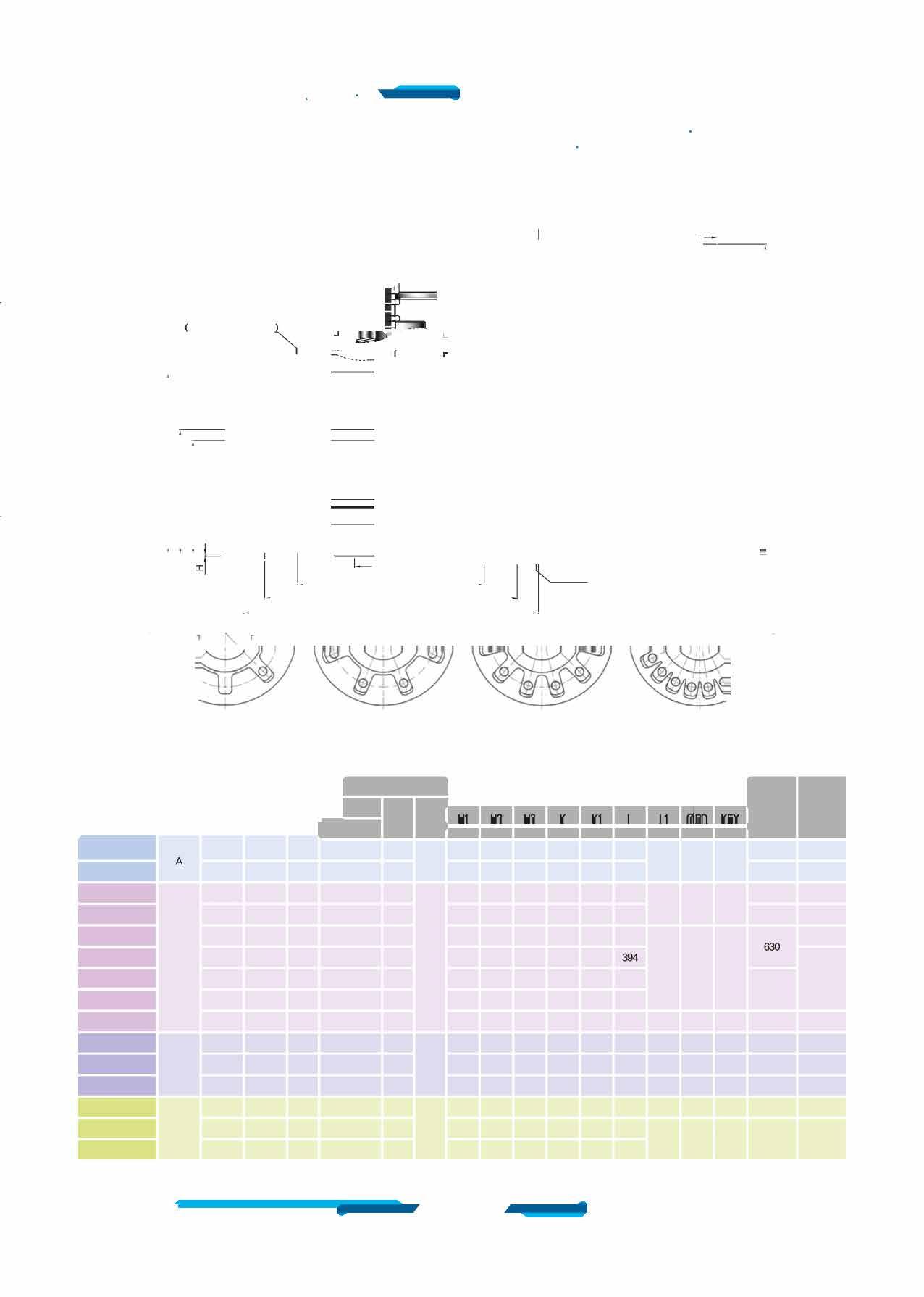
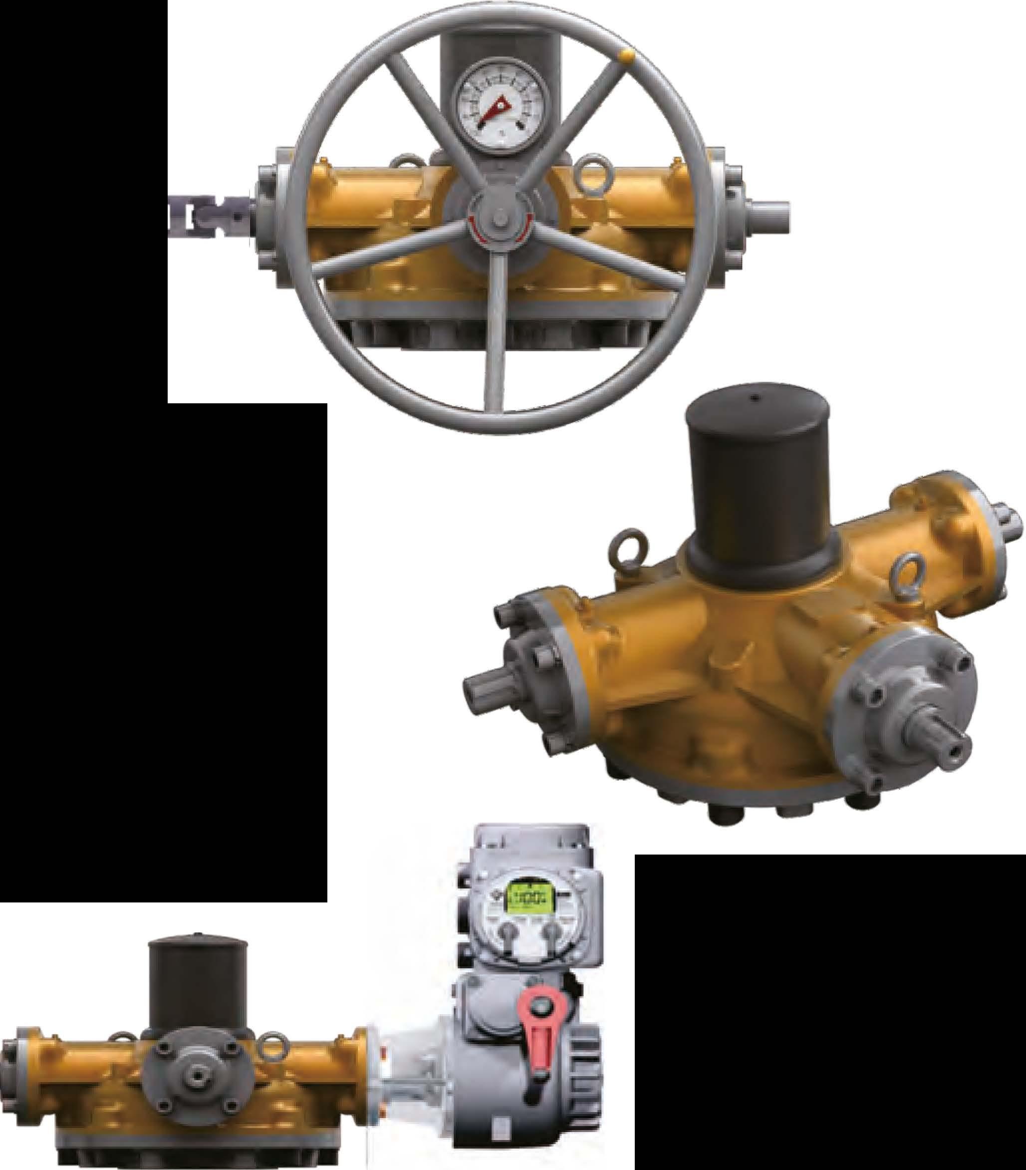
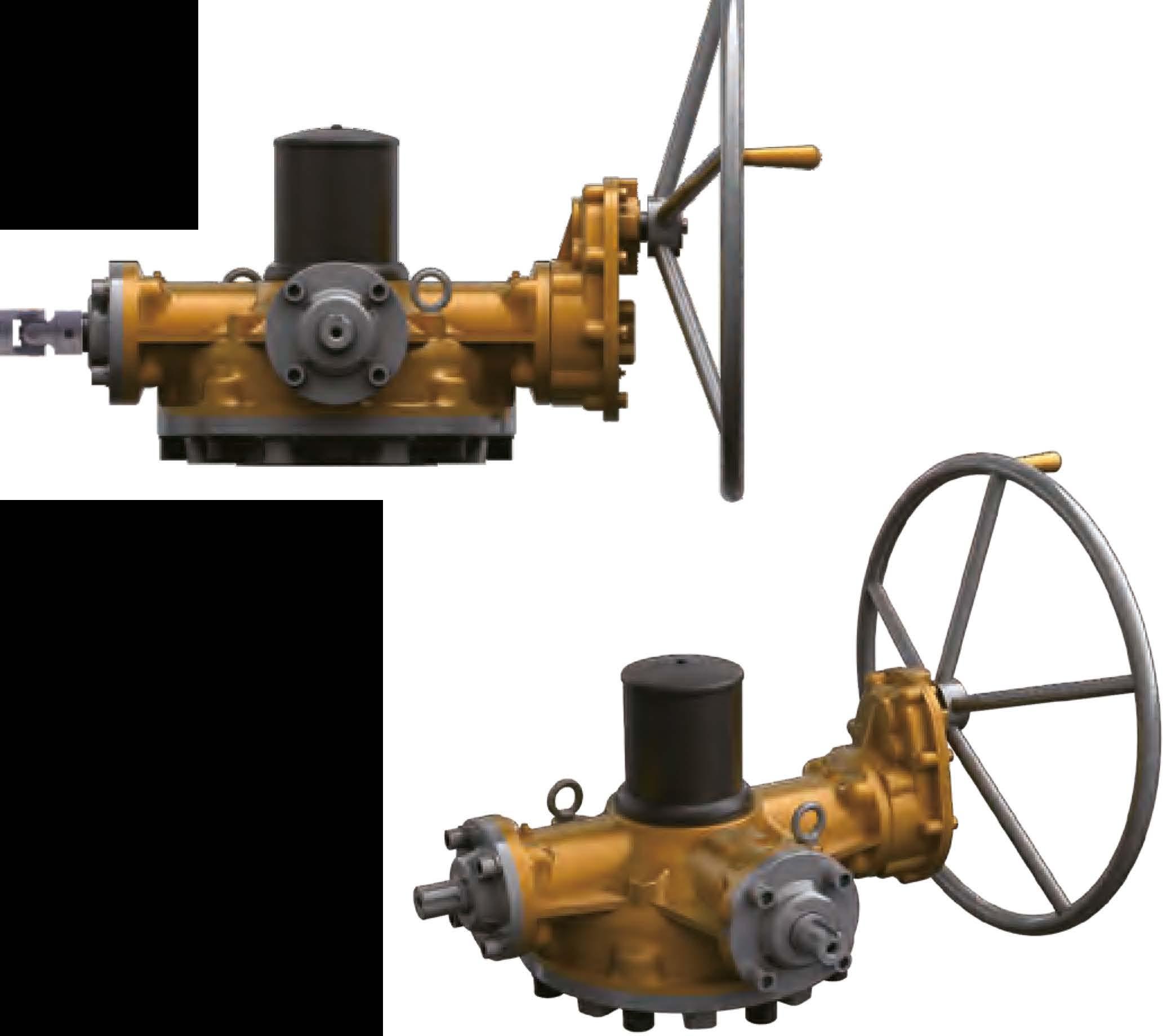
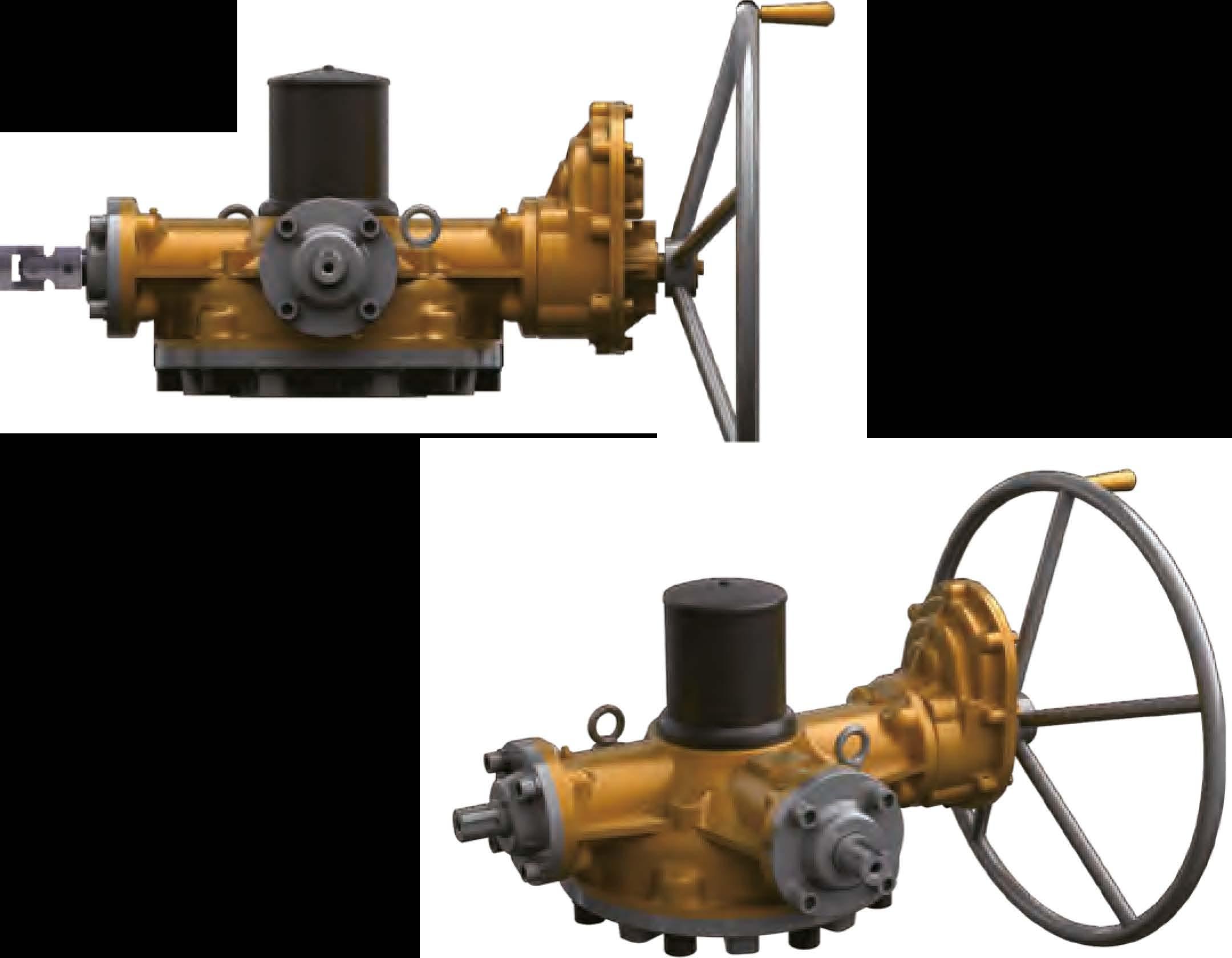
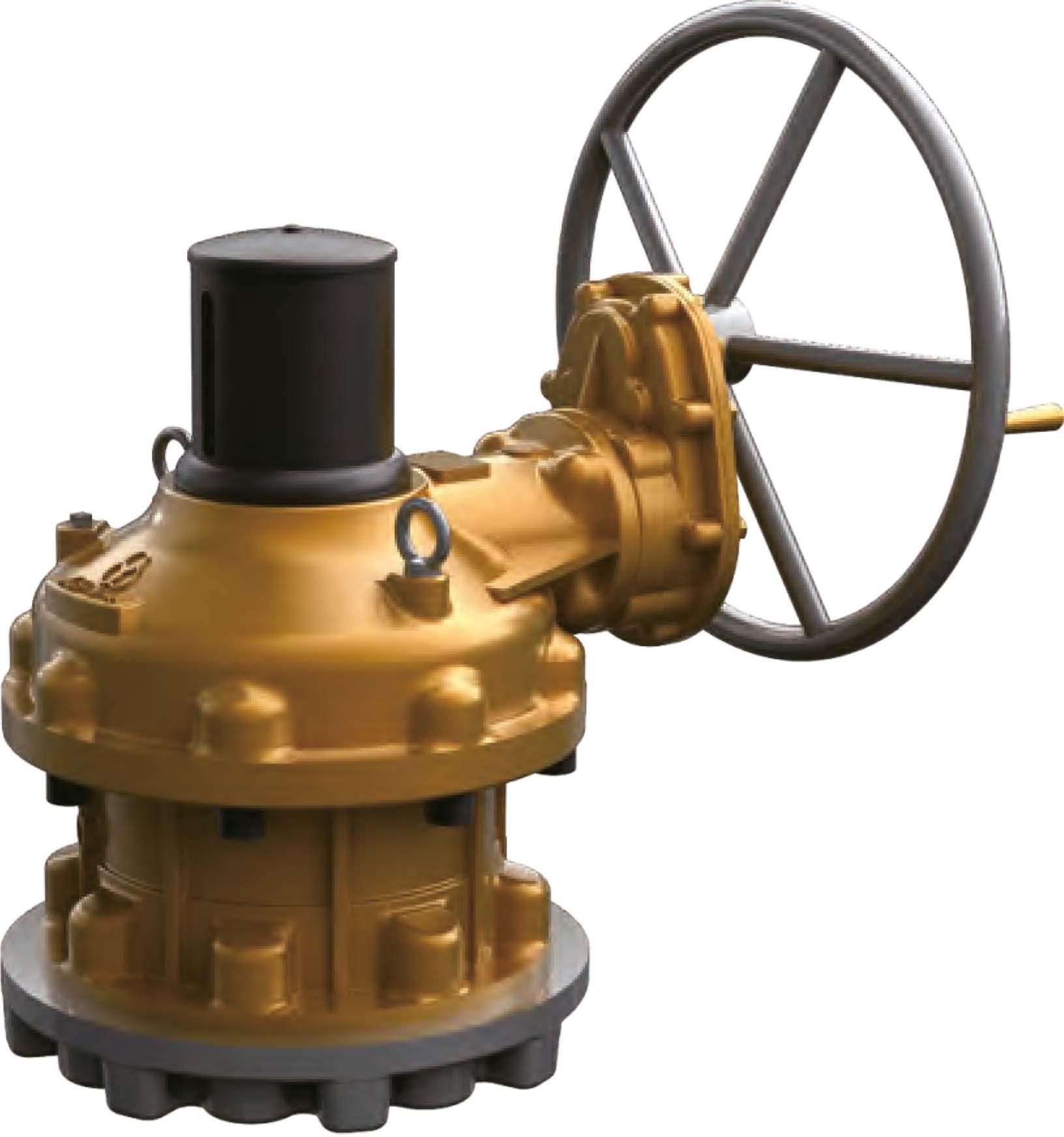
Hand Wheel Type & Chain Wheel Type
IYIDV Type & Flange Dimensions
Fix Type & Hammer Blow Type Etc.
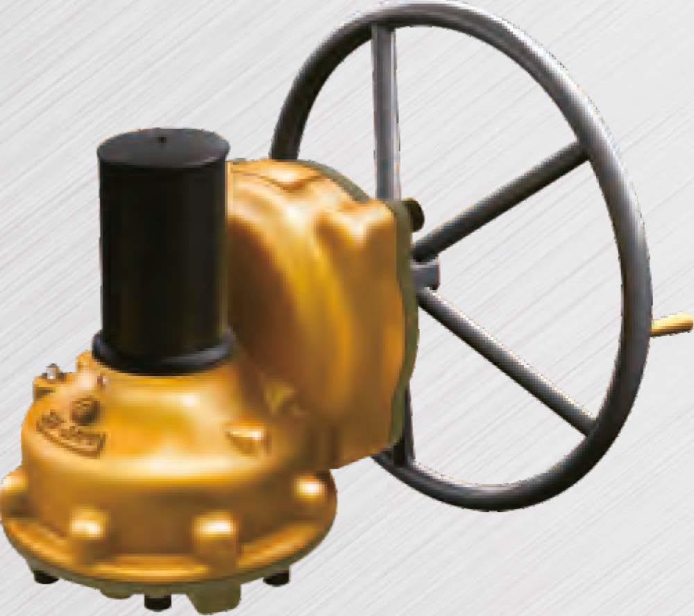
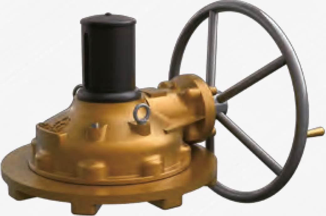
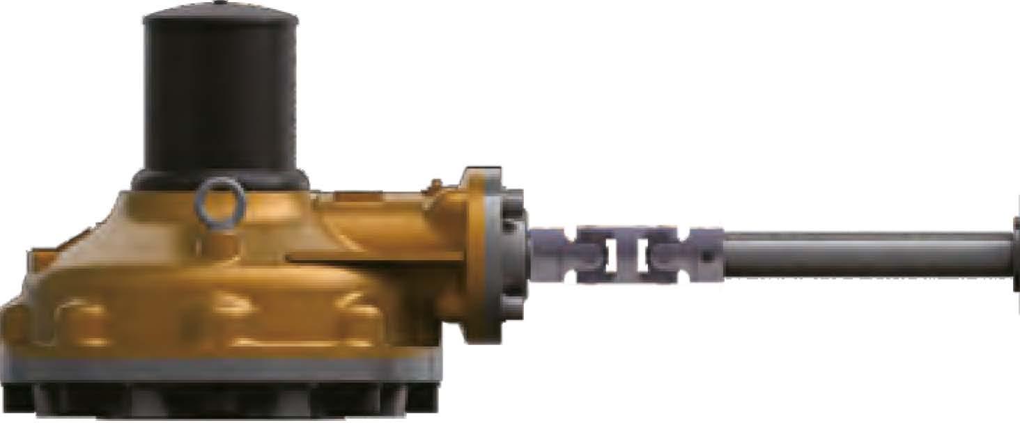
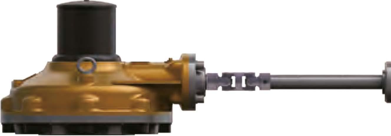
Standard Type A - Thrust & Torque
Horizontal Input
Standard Type A - Thrust & Torque
Horizontal Input
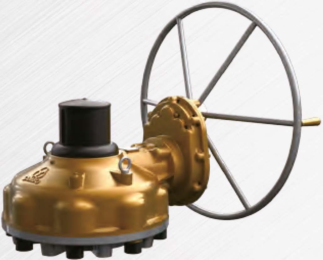
Standard Type A - Thrust & Torque
Horizontal Input
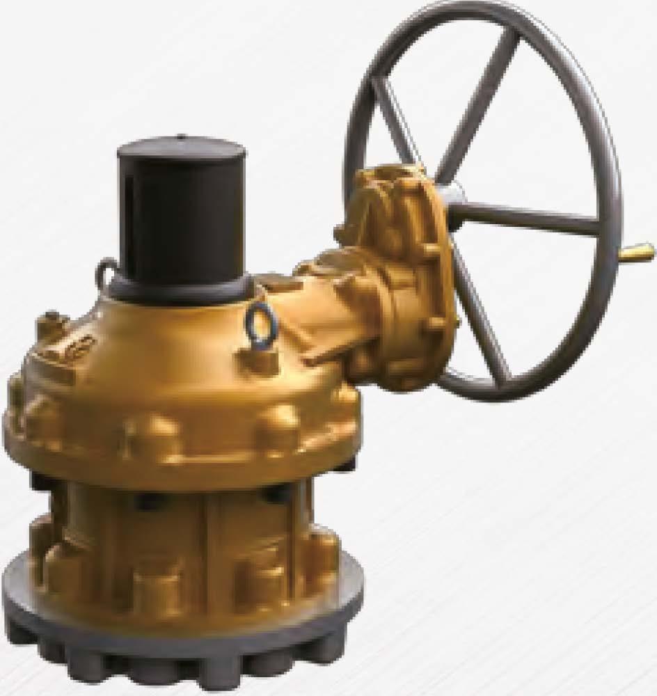
Standard Type A - Thrust & Torque
Horizontal Input with Single Reduction Gear Attachment
Standard Type A - Thrust & Torque (Twin Shaft)
Horizontal Input with Single Reduction Gear Attachment
Standard Type A - Thrust & Torque
Horizontal Input with Double Reduction Gear Attachment
Standard Type A - Thrust & Torque (Twin Shaft)
Horizontal Input with Double Reduction Gear Attachment
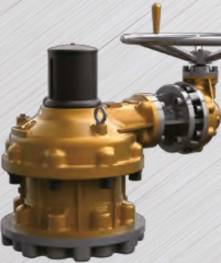
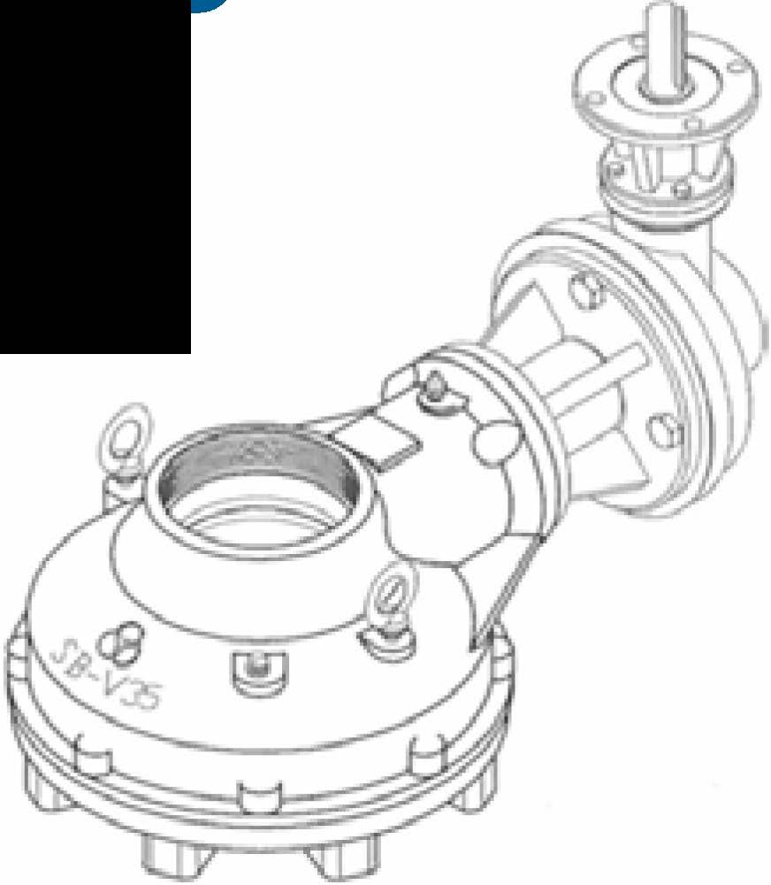
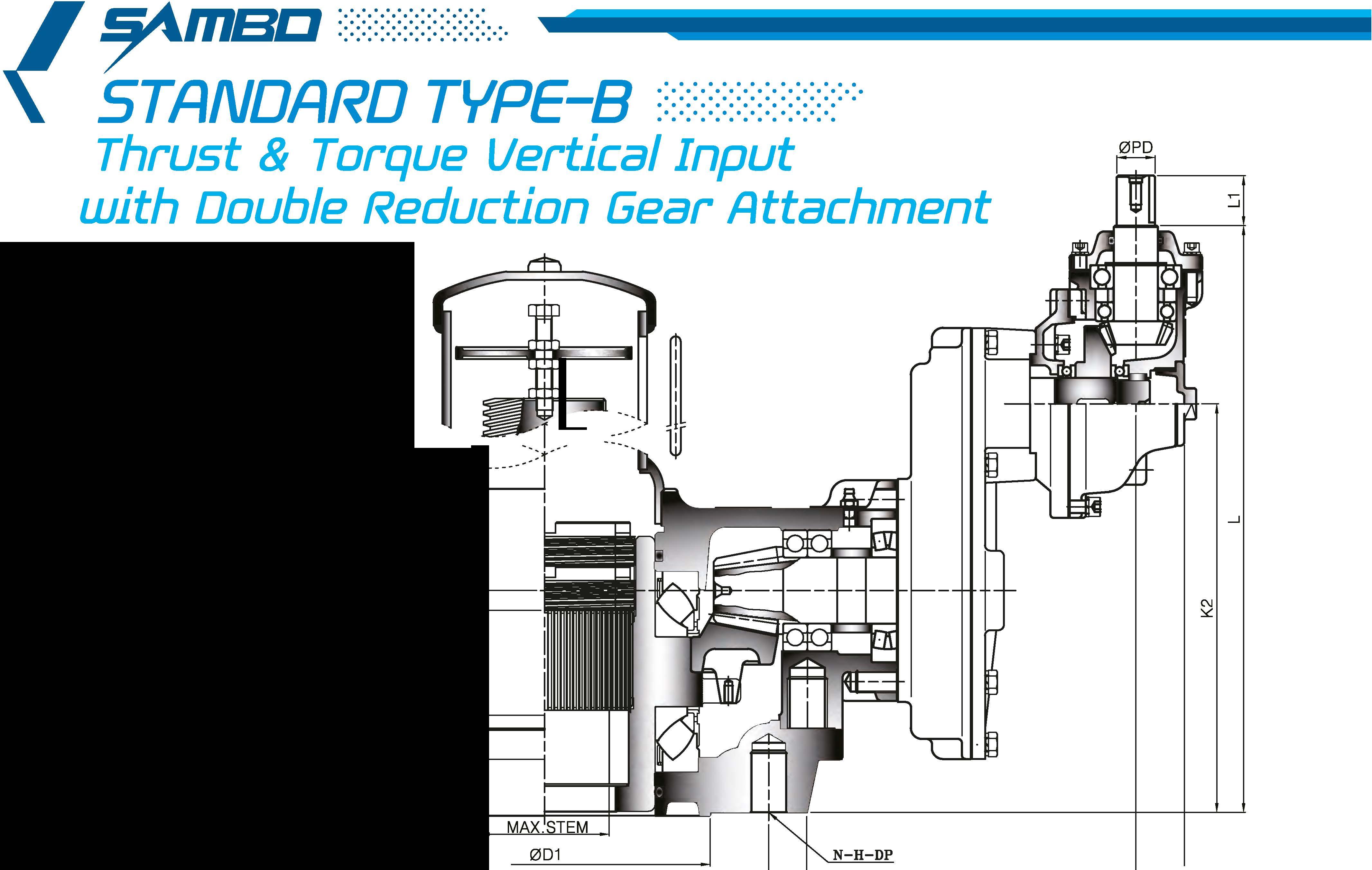
Standard Type B - Thrust & Torque
Horizontal Input with Single Reduction Gear Attachment
Standard Type B - Thrust & Torque
Horizontal Input with Double Reduction Gear Attachment
Standard Type C - Torque only Lug Drive
Horizontal Input
Standard Type C - Torque only Lug Drive
Horizontal Input with Single Reduction Gear Attachment
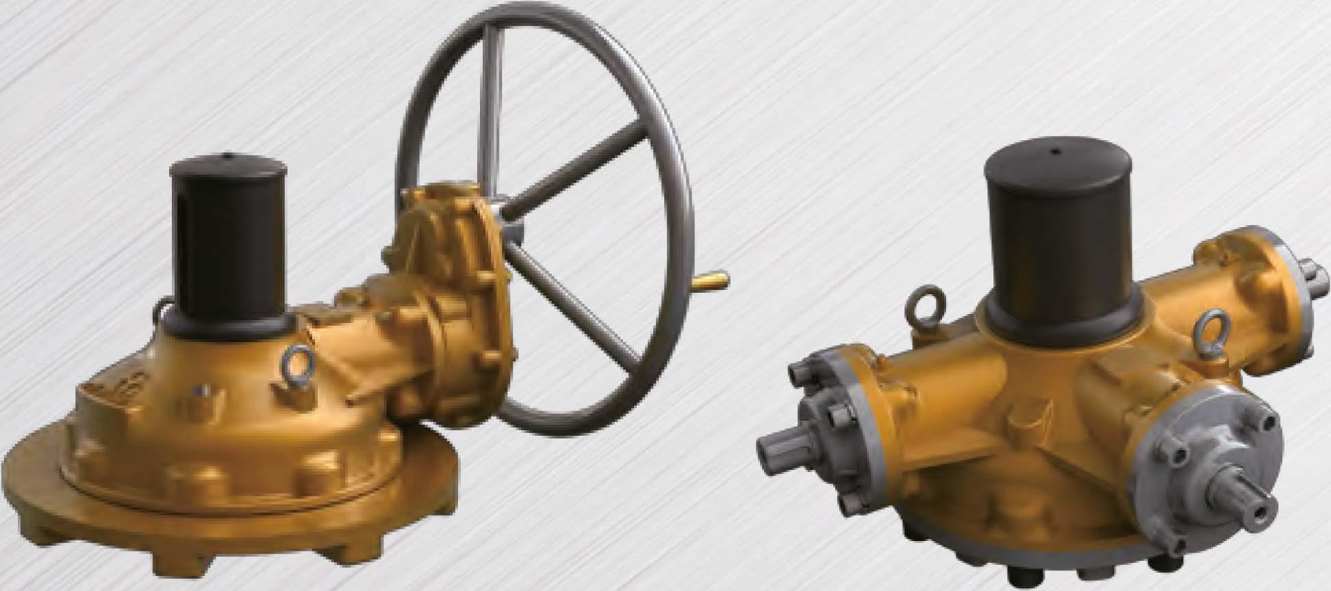
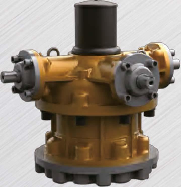
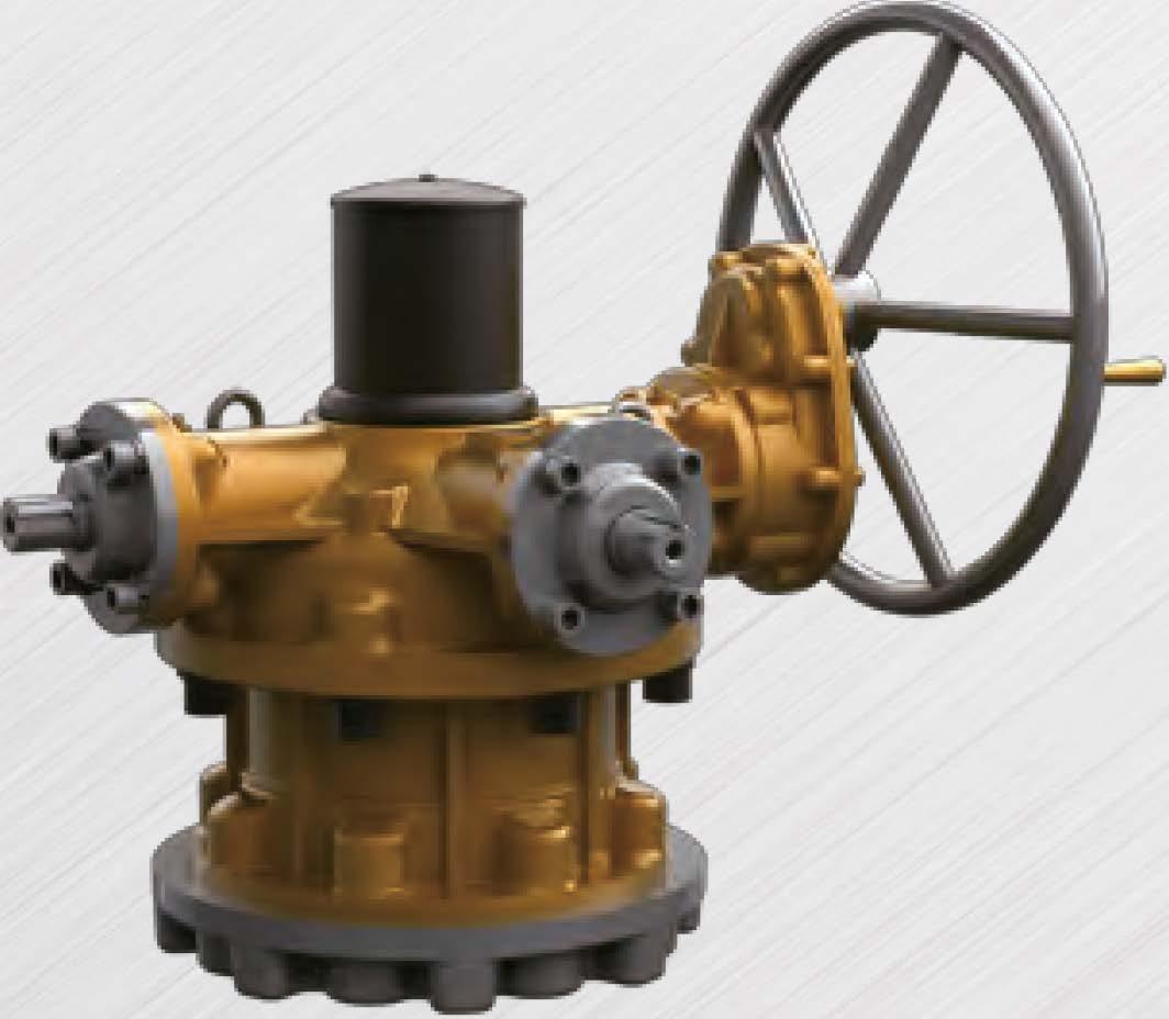
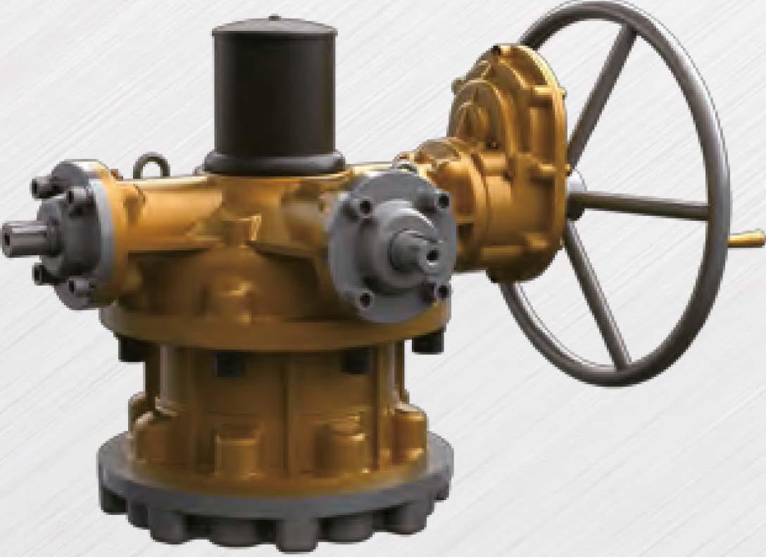
Standard Type D - IYlultiple Input Shaft - Thrust & Torque
Horizontal Input
Standard Type D - IYlultiple Input Shaft - Thrust & Torque
Horizontal Input with Single Reduction Gear Attachment
�ndard Type D - IYlultiple Input Shaft - Thrust & Torque /fiorizontal Input with Double Reduction Gear Attachment
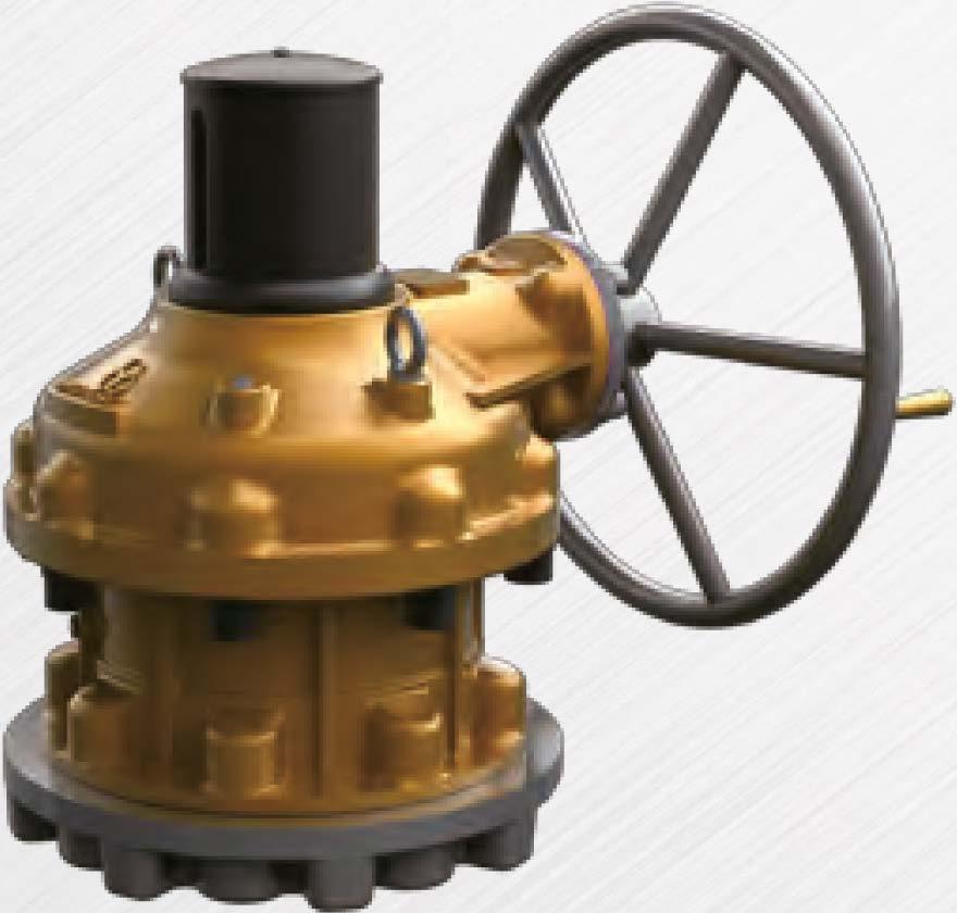
Standard Type E - High Load Thrust & Torque
Horizontal Input
Stan"dard Type E - High Load Thrust & Torque
Horizontal Input with Single Reduction Gear Attachment
Standard Type E - High Load Thrust & Torque (Twin Shaft)
Horizontal Input with Single Reduction Gear Attachment /
Standard Type E - High Load Thrust & Torque
Horizontal Input with Double Reduction Gear Attachment
Standard Type E - High Load Thrust & Torque (Twin Shaft)
Horizontal Input with Double Reduction Gear Attachment
Standard Type E - High Load Thrust & Torque
Vertical Input with Single Reduction Gear Attachment
Standard Type F - IYlultiple Input Shaft: High Load Thrust & Torque
Horizontal Input /
Standard Type F - IYlultiple Input Shaft: High Load Thrust & Torque
/Horizontal Input with Single Reduction Gear Attachment
Standard Type F - IYlultiple Input Shaft: High Load Thrust & Torque
Horizontal Input with Double Reduction Gear Attachment
Standard Type F - IYlultiple Input Shaft: High Load Thrust & Torque
Vertical Input with Single Reduction Gear Attachment
�izean«□mponentspeciticationinthiscataloguearesubjecttochangewi�priornoticeforqualityimprovement.
•IYlarkhas enchangedandupdated. /
•
•


Ifthere is no
from
Allmaterialof round barhandwheelare made by
• IYlark has been changed and updated.
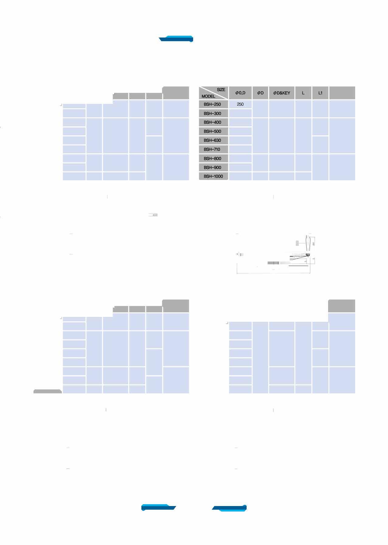
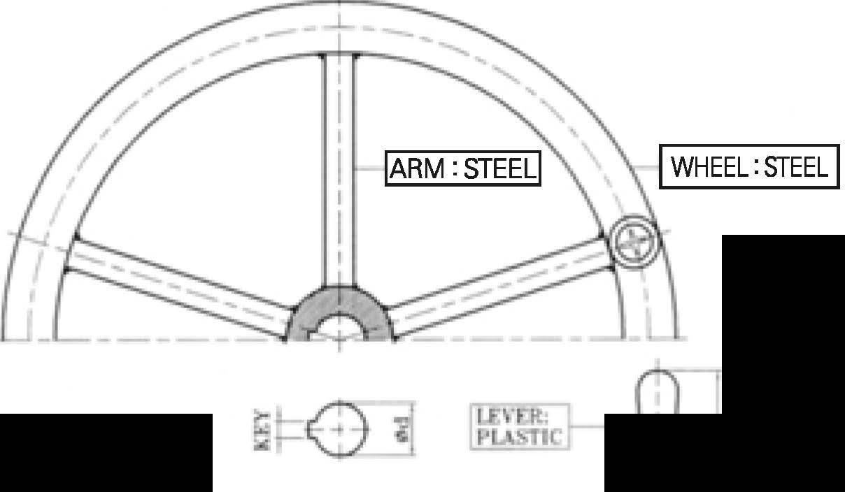

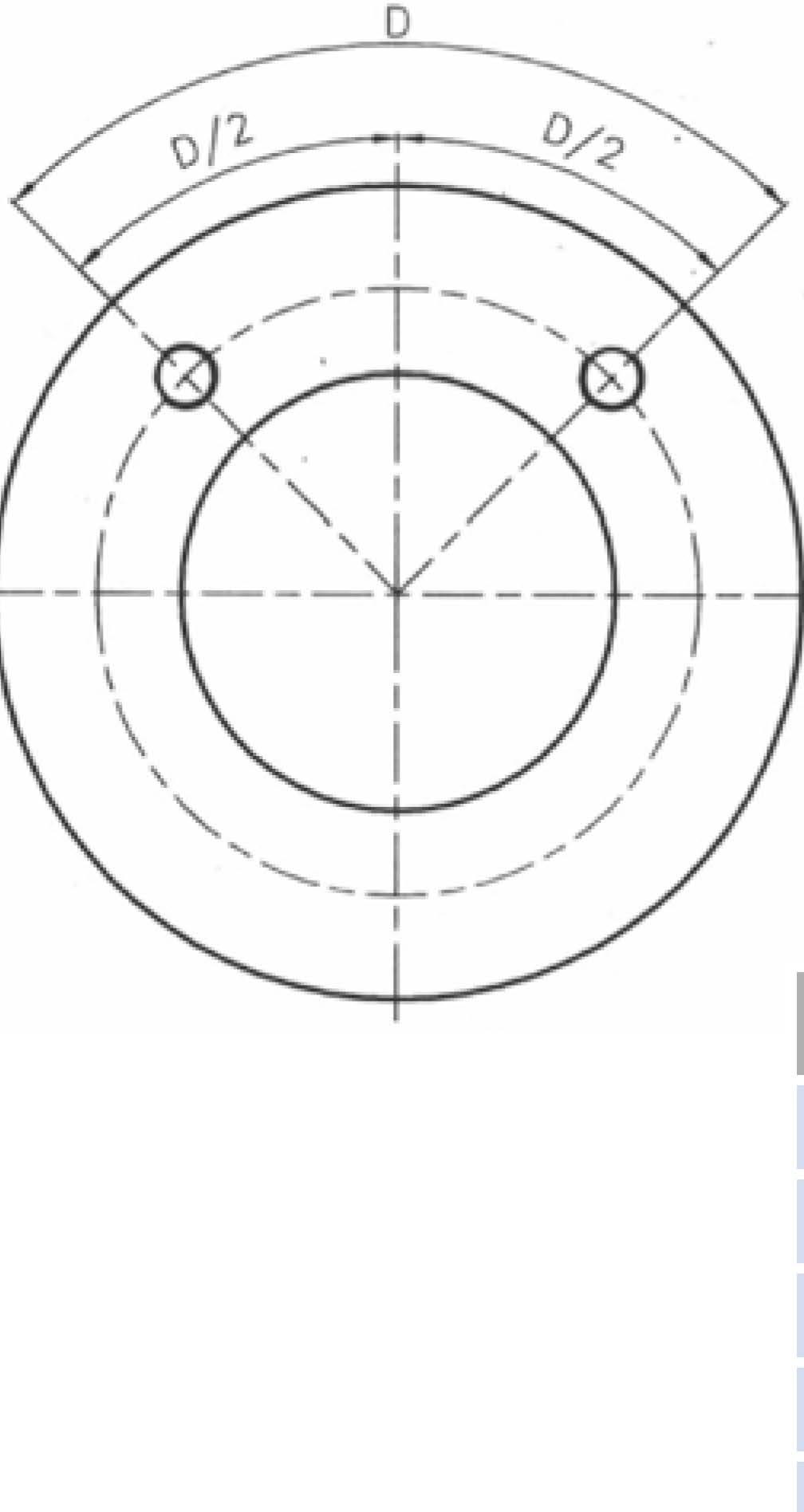
(!)50(16X10)
This Handwheel is the type using alr impact wrench and it can be made properly according to customer' s request

Chainwheel has 2 types

• First, hammer type which isjoined with handwheel.
• Second, gear type which is adhered to gear directly.
• material : sprocket rim (FCD4S□l, guide arm (AS76-104S), chain (steel+zn)
Global Leader


Stlrdardlype
SUpportType
FlangeType Fa,gelype


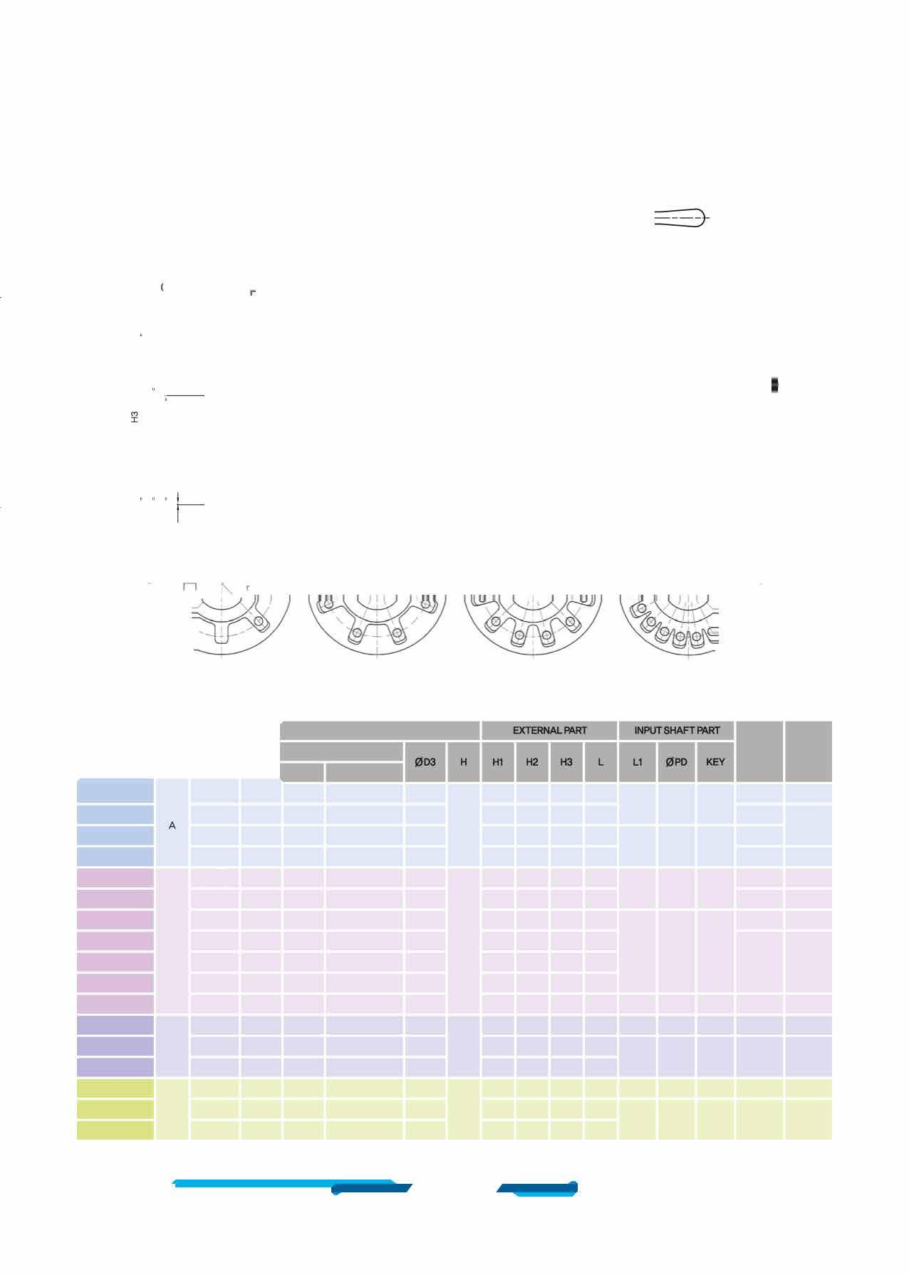
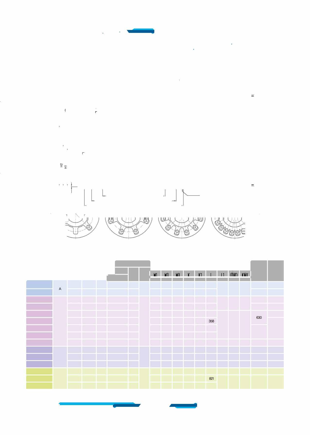
a>30(10XB)
a>35(10X8)
d)40(12XB)
d)45(14X9)
70 6 90 8 110 10
(1)55(16X10)
(1)65(18X11)
(1)65(18X11)
a>80(22X14)
a>90(25X14)
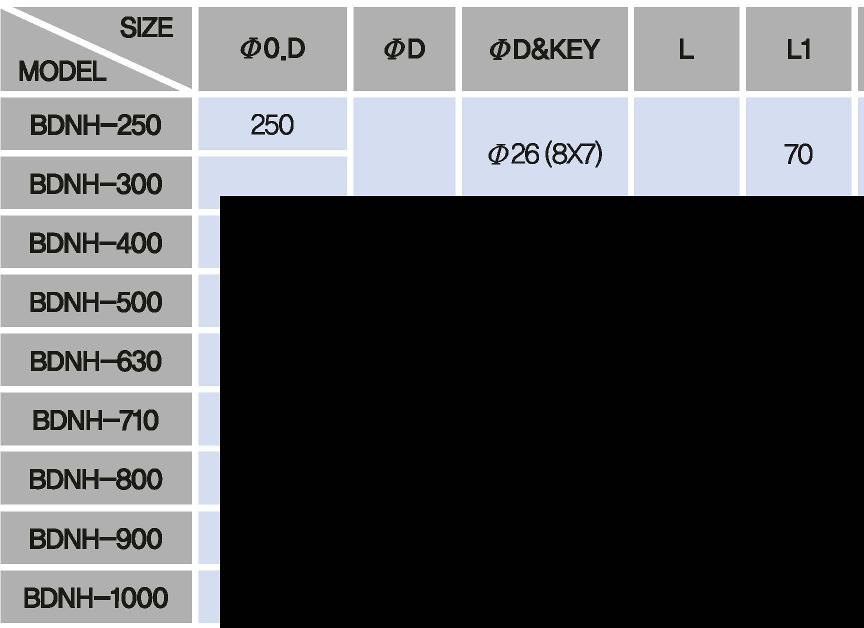
StlrdardType
FlangeType
SB-V2-1S,1SD
SB-V3-1S,1SD
SB-V35-1S,1SD
SB-V4-1S,1SD
SB-VS-1S,1SD
SB-V55-1S,1SD 70 6 90
SB-V6-1S,1SD
SB-V7-1S,1SD
SB-V75-1S,1SD
SB-V8-1S,1SD
SB-V85-1S,1SD
SB-V9-1S,1SD
SB-V10-1S,1SD
Max_d)D&Key
a>30(10XB)
a>30(10XB)
a>35(10XB)
a>40(12X8) 8
a>45(14X9)


SUpportType


(1)'20(6X6)
(l)25(8X7)
a>35(10XB)

d)45(14X9) 70 6 90 8 110 10 70 6 90
(1)55(16X10)
(1)70(18X11)
(1)90(25X14)
(1)120(32X18)

Size and component specitication in this catalogue are subject to change without prior notice for quality improvement. • IYlark has been changed and updated.

(1)55(16X10)
a>70(18X11)
Max_d)D&Key
a>25(8X7)
a>30(10XB)
a>35(10XB)
8 a>45(14X9)
(l)55(16X10)
a>70(18X11)
(1)70(18X11)
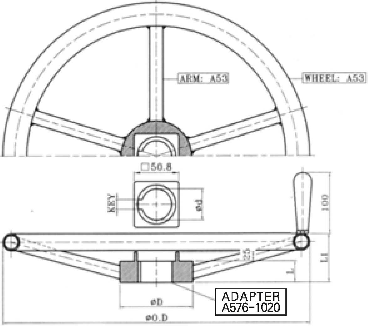
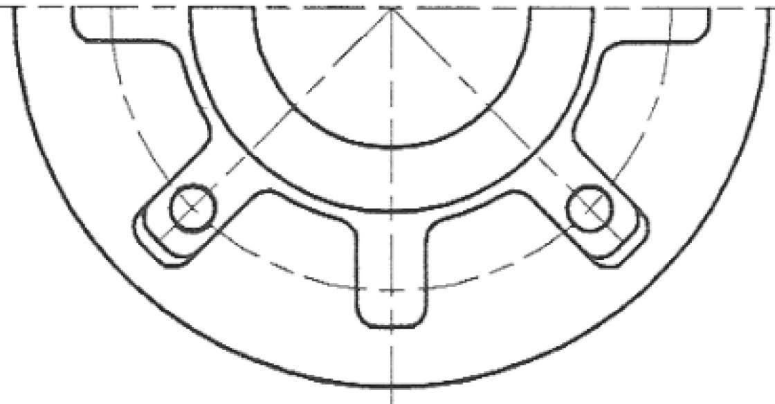
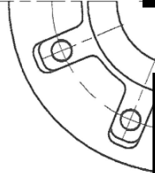
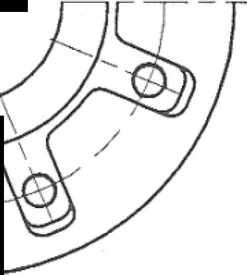
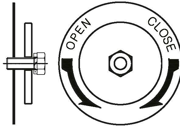
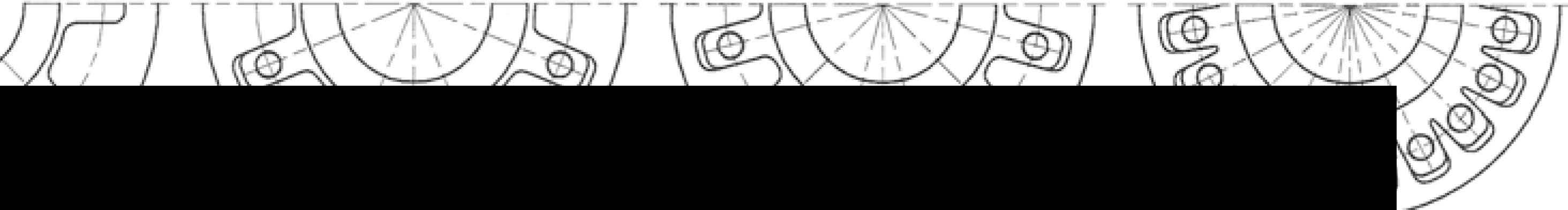
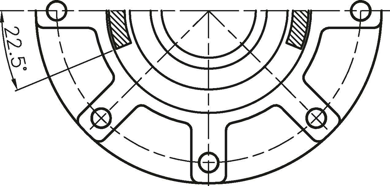
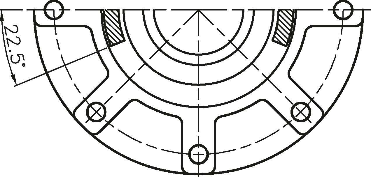
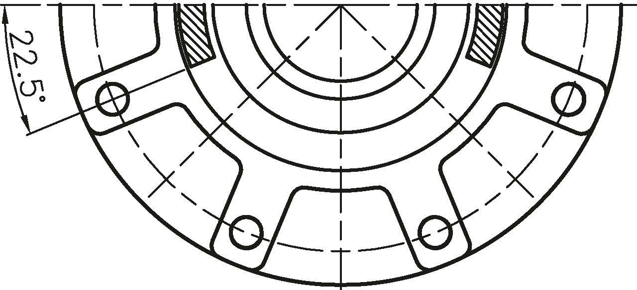
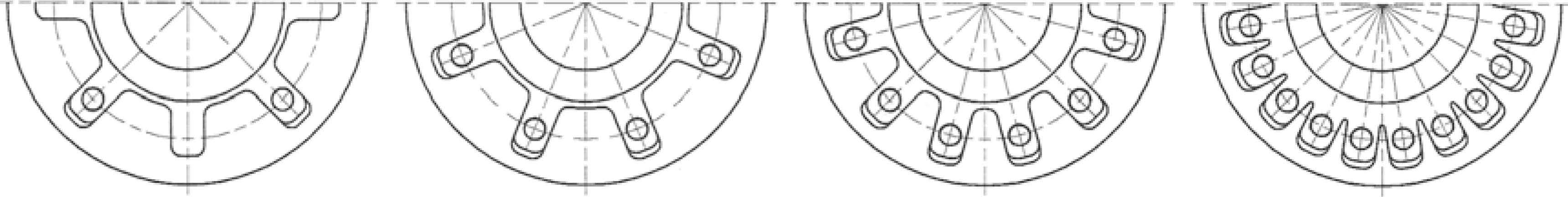
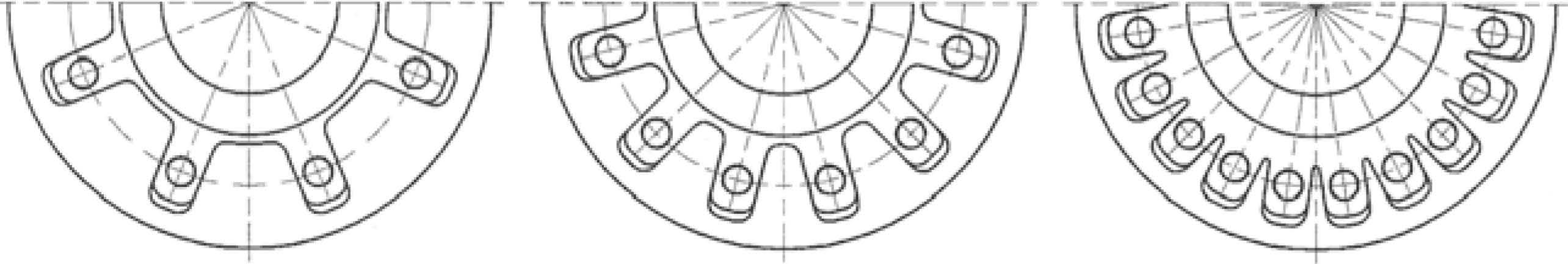
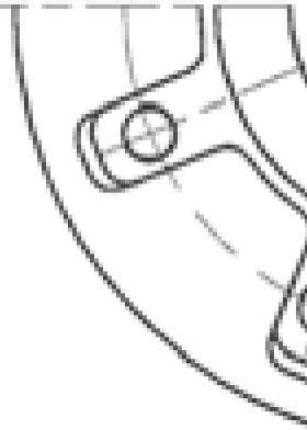
BevelGearshavetheab.ilitytabe assembledwith'tost-/Ylotion-[Hammerblow]"or with"No-Lost/Ylotion"outputdriuearrangement IYI•0•V TYPE / DUAL TYPE

HANDLE TYPE

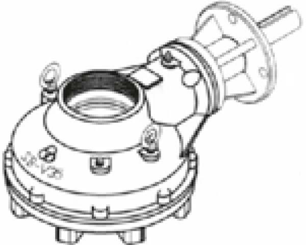
SPIRAL BEVEL GEAR
Fix Type (IYI • 0 • V/Dual} >>> No-Lost IYlotion
This type eliminates the gap in the lug drive between the Spiral Bevel Gear and Drive Sleeve. It is the preferred method for Electric Actuators having positioning control capability.
BEVEL GEAR
Hammer Blow Type (Handle) >>> Lost IYlotion
This type eliminates the gap in the lug drive between the Spiral Bevel Gear and Drive Sleeve enabling a momentary impact. It is the preferred method for all IYlanual operation and for Electric Actuators of Wedge Gates and Globe Valves.
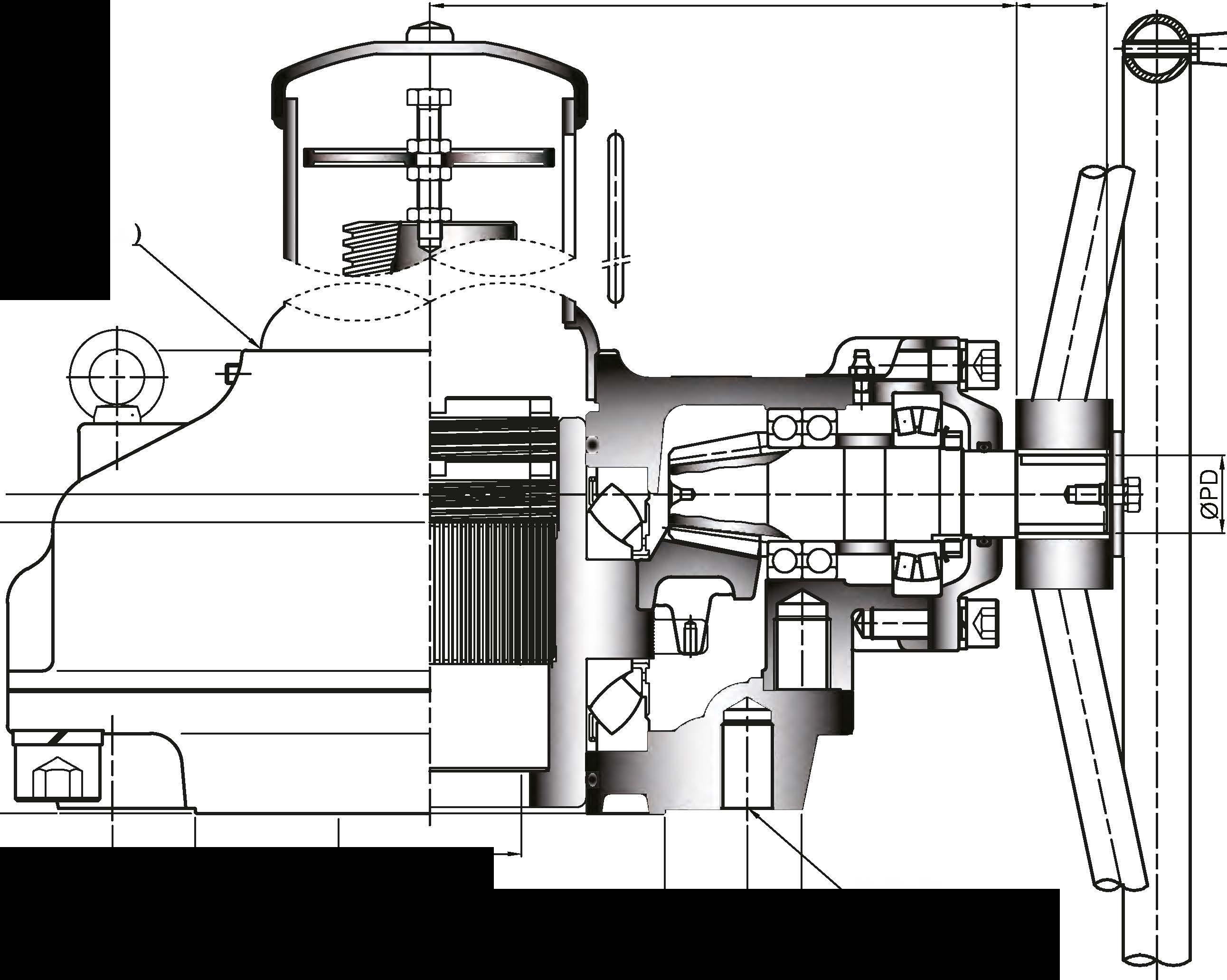
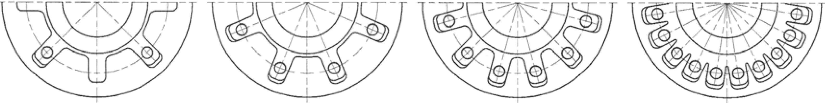
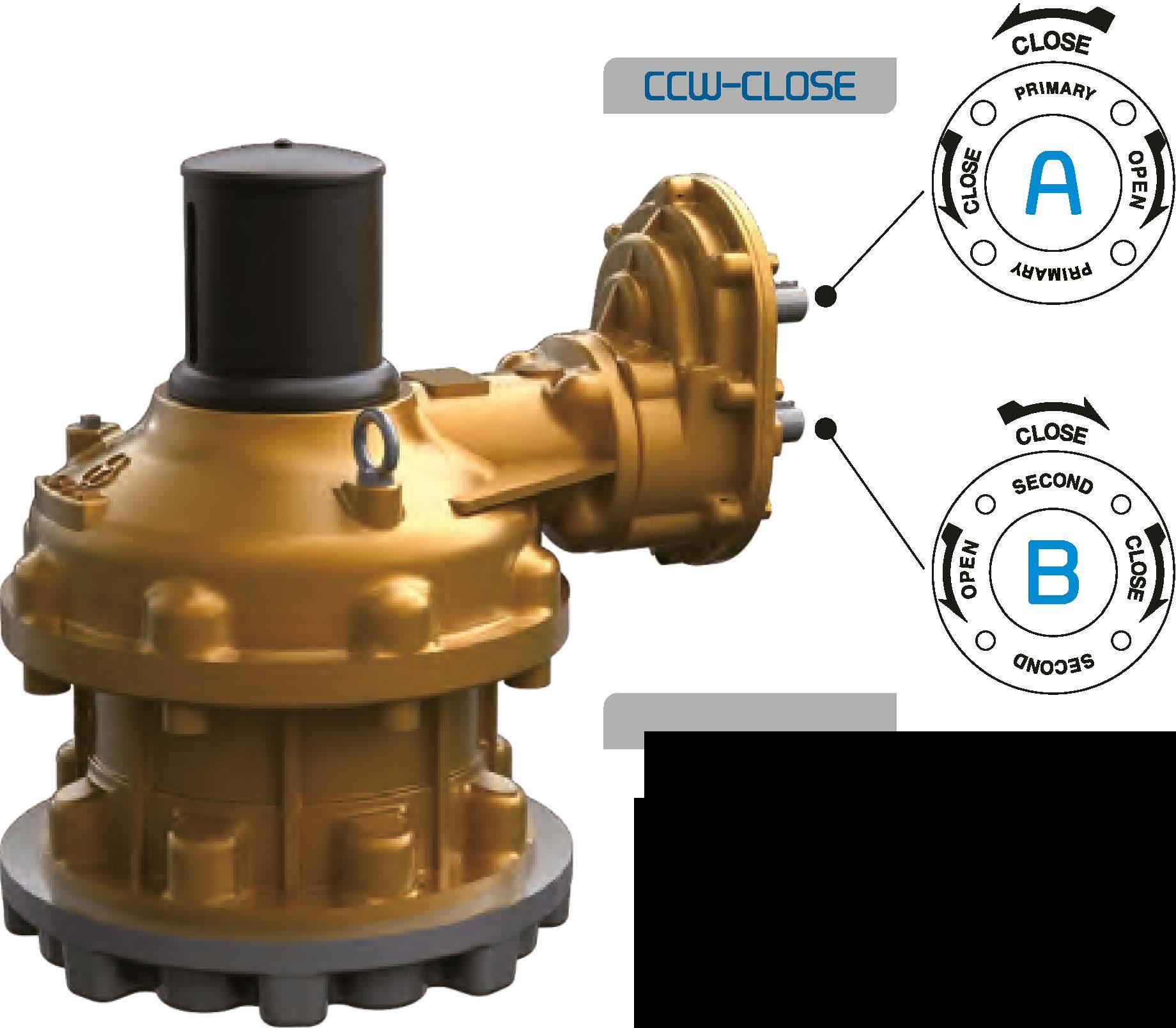
There are two input shafts in the below support box type. One shaft is for high speed and the other shaft is for low speed.
Provides maximum mechanical advantage for seating and unseating of valves.
Allow for less turns after valve has been unseating.
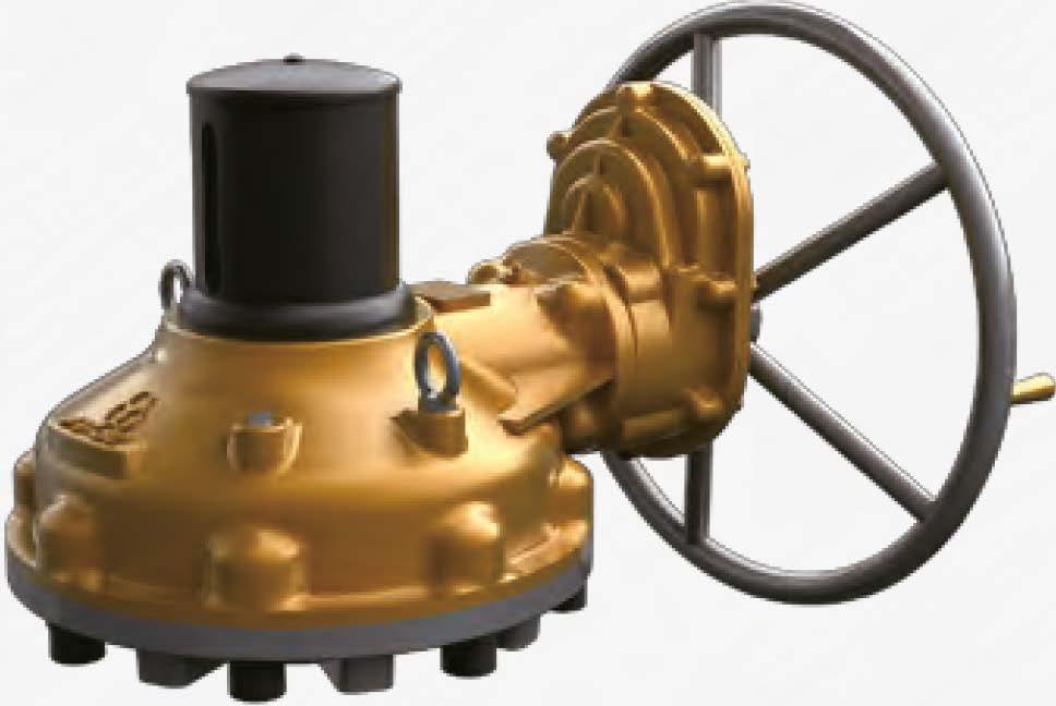
The below input shaft type is used to require Gear Actuators which is operated by 2 spindles. As option, there are motorized type, dial type and manual type.
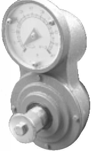
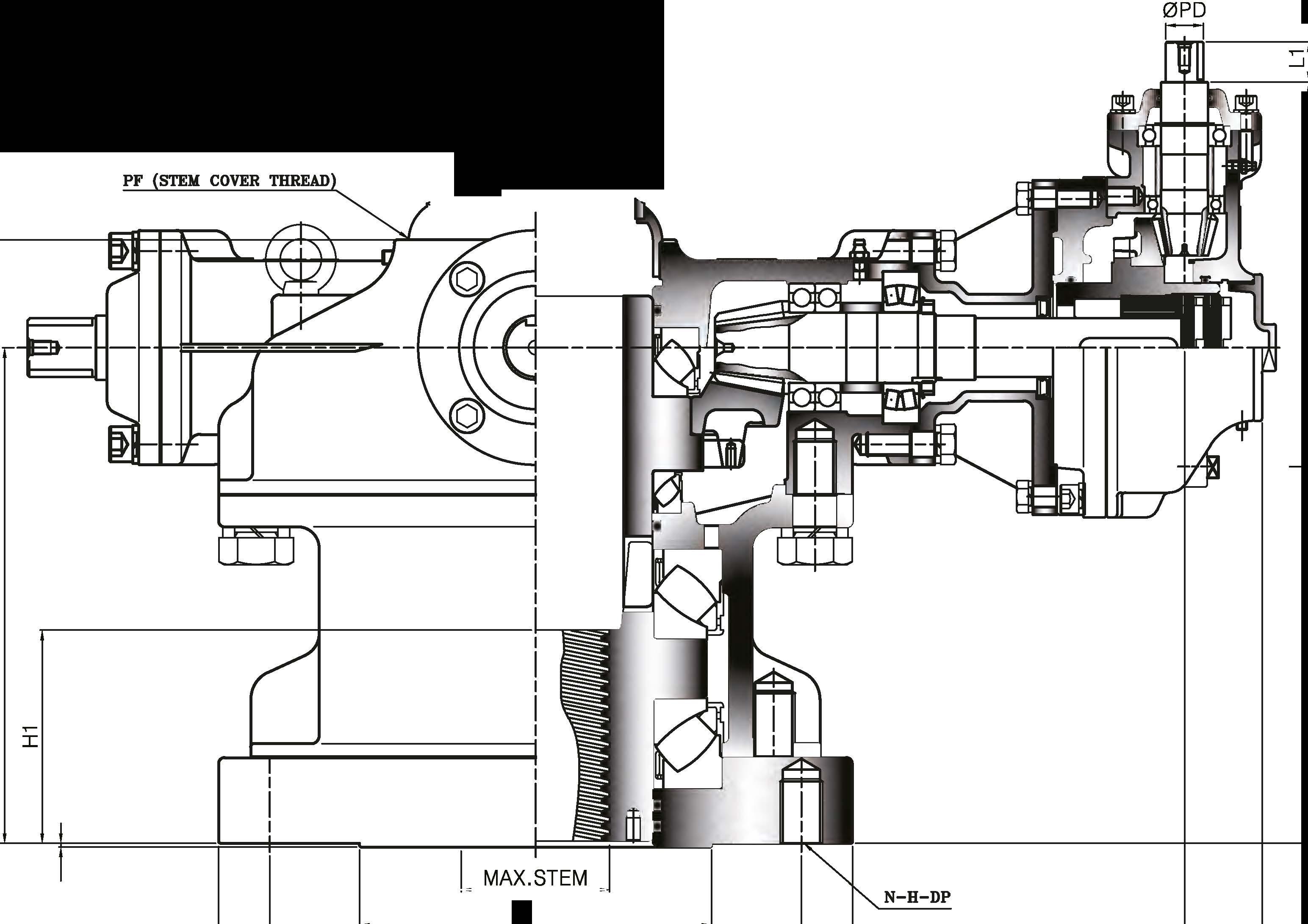
Stem cover for valve can be offered as AS3, SUS3O4, polycarbonate and etc. Stem cover and indicator sets can be made by several different types. The length of stem cover will be changed as per customer' s request.
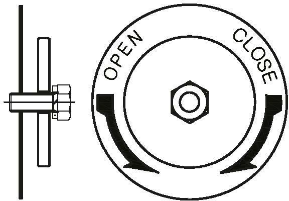
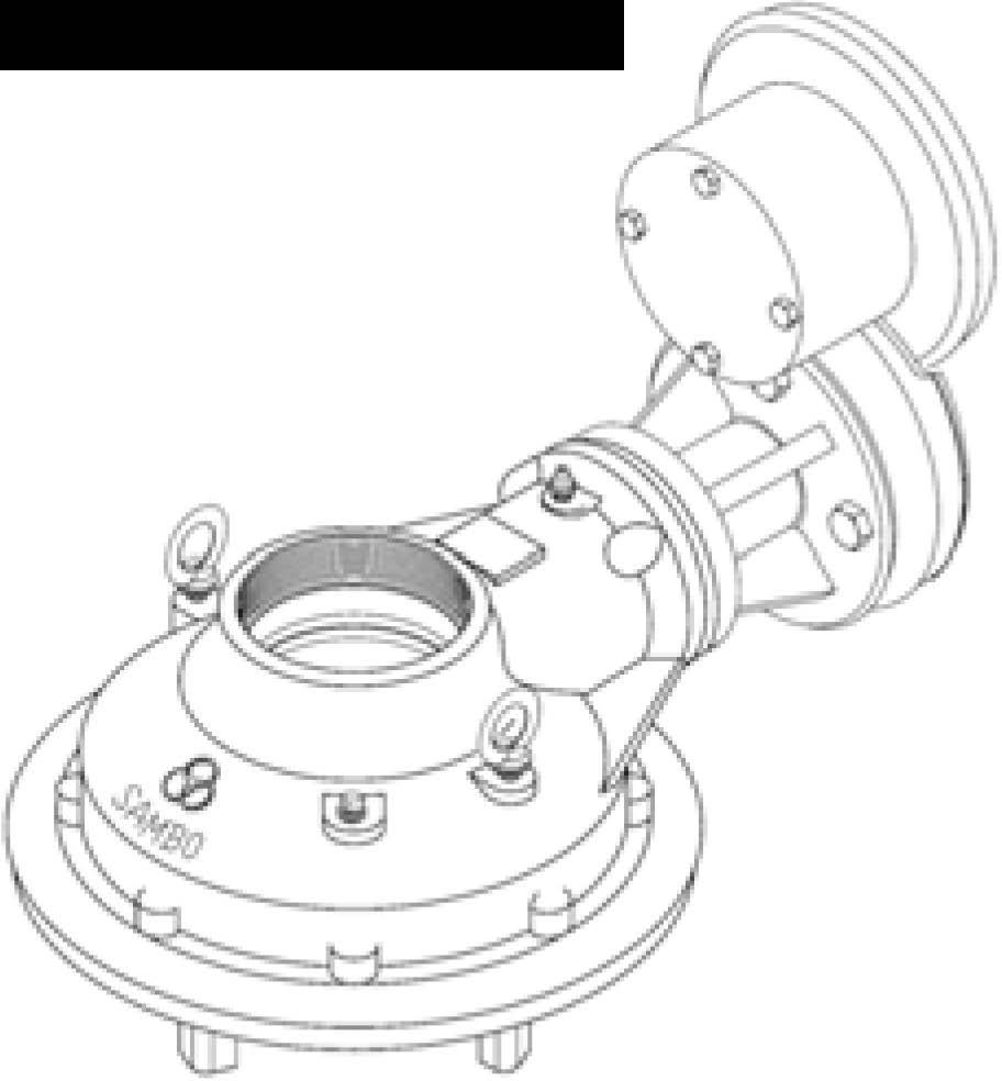
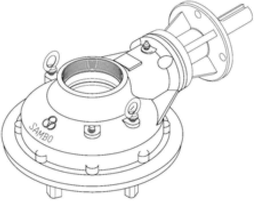
Samba' s standard input shaft rotation is based on a clockwise input resulting in a clockwise output (Clockwise In = Clockwise Out). The reverse rotation can be operated. As per customer' s request, it can be made by such types as buried, submersible, marine, radiation and high & low temperature service and etc. Also, Gear ratio and specification of flange can be changed.


SB-MT-V4
SB-MT-V5
SB-MT-V55
SB-MT-V6
• This series suitable for use with Gate & Globe type valve. Also sluice gates and any other type requiring linear motion for thrust and torque applications.
• Unique Top Entry Replaceable Stem Nut. High Tensile Aluminum bronze material providing corrosion and abrasion resistance.
• Castings are Ductile Iron, class 65-45-12 providing high strength and impact resistance.
• Heavy duty roller bearings supporting both radial & axial thrust loads.
• Gears are IYlachine cut, heat treated and ground for optimum operation Units are completely □-Ring Sealed suitable for temporary submergence to meet Ip67 class.
• IYlany options, such as hand wheels, chain wheels, stem covers, position dial indicators are available.
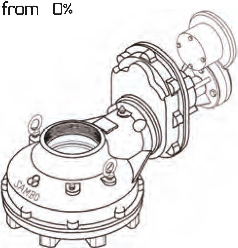
A unique local position dial indicator is available. It is graduated in percent from 0% (dose) to 100% (open).
.eader
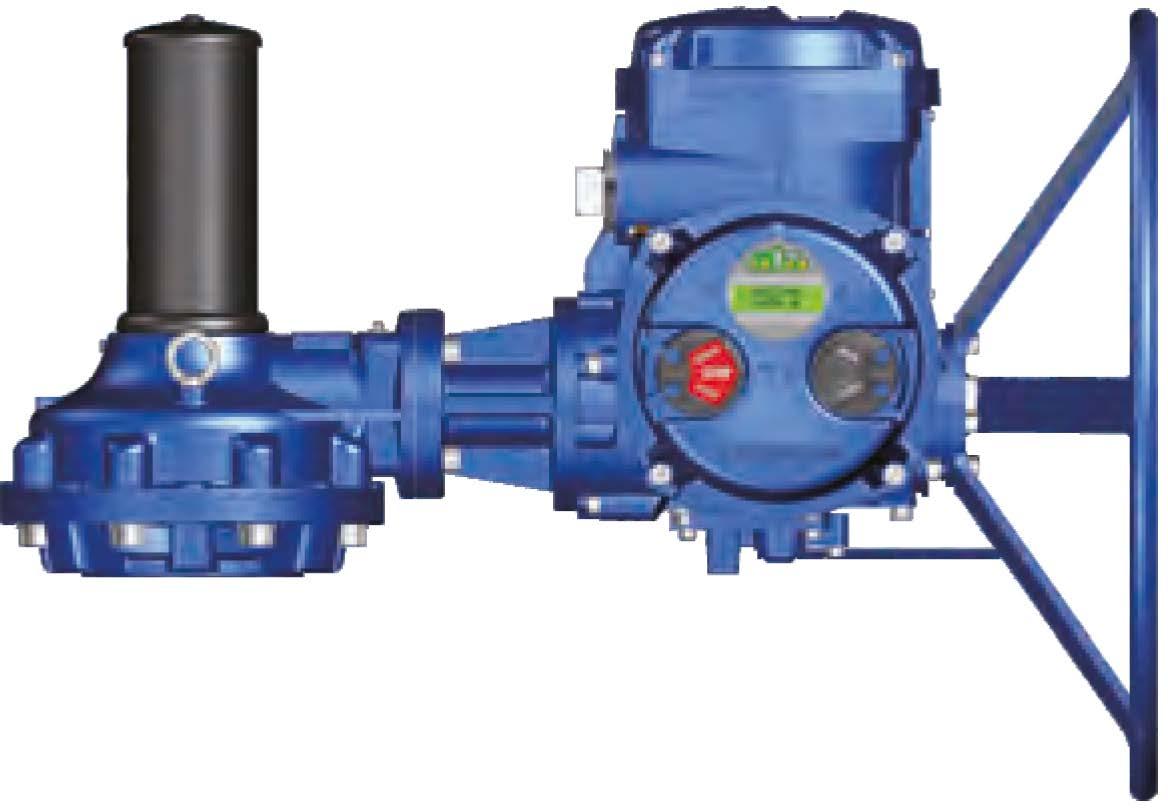
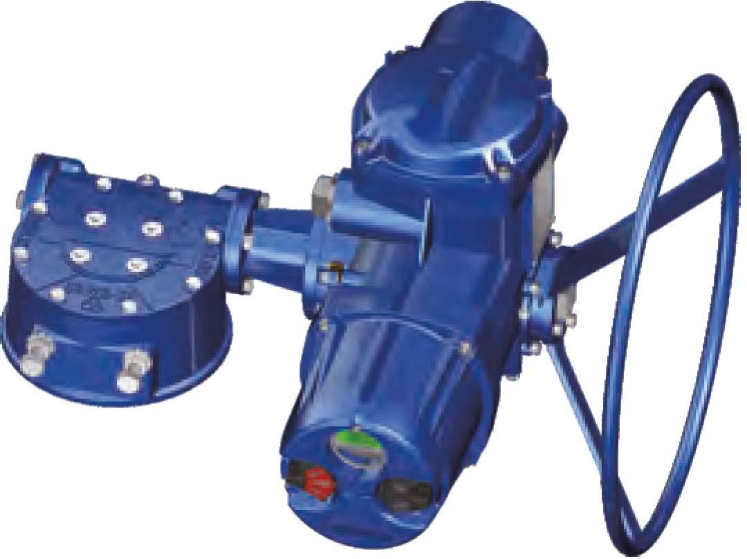
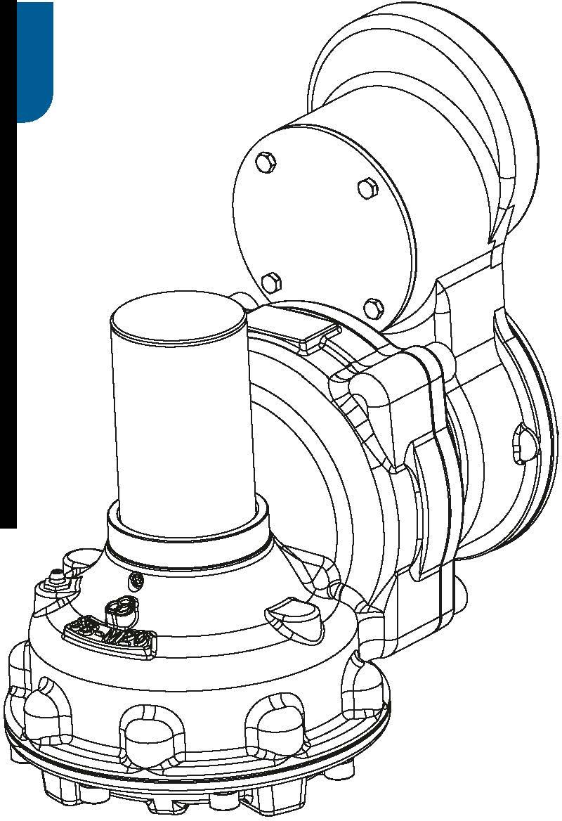
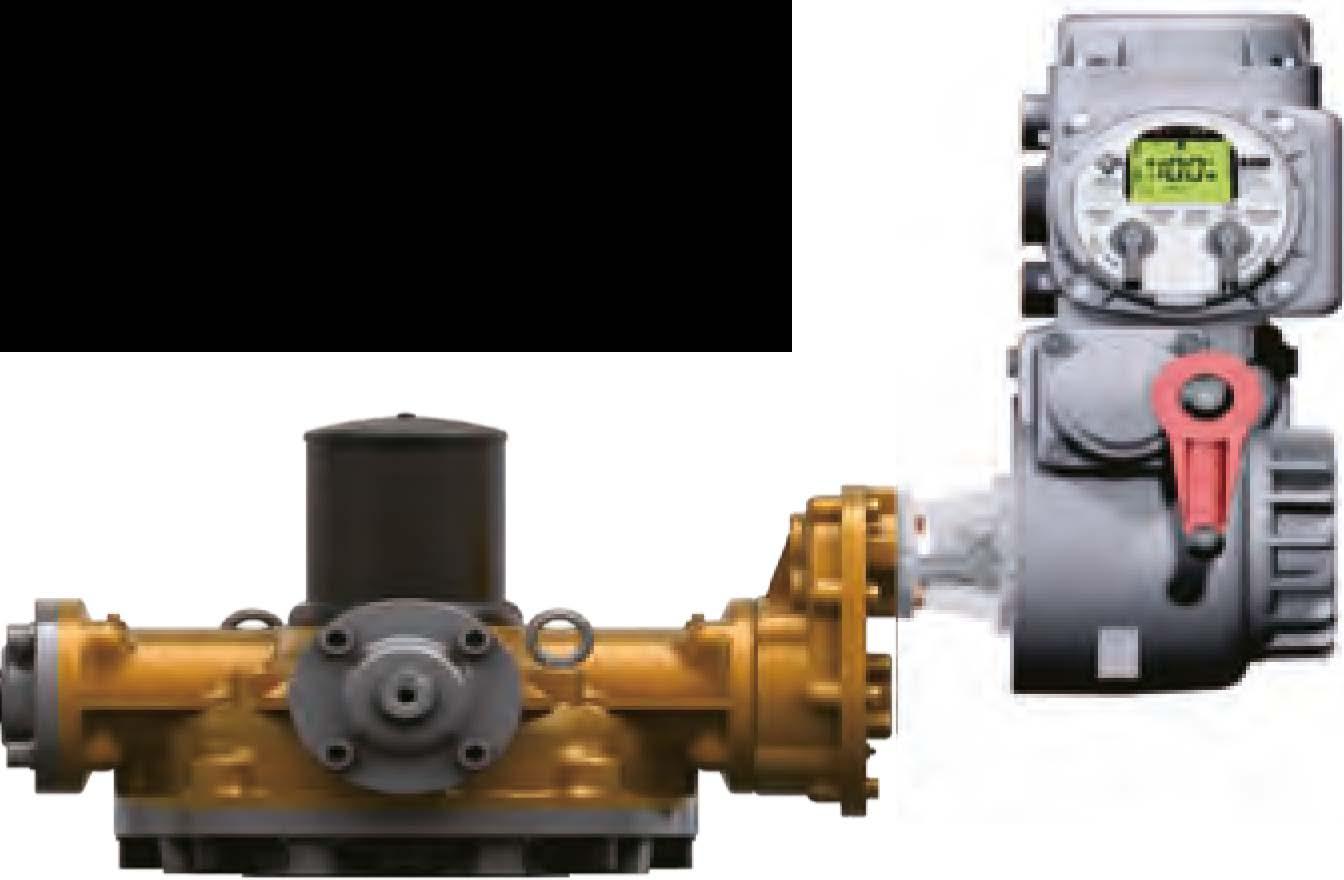
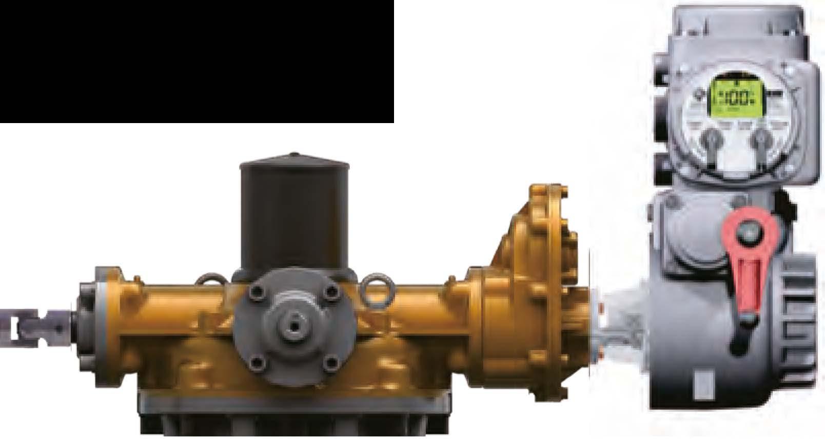
Bevel Gear can be provided with IYlotor actuator input flanges to accept standard ISO IYlounting Base.


*SB-SP-VS20 F-12 85
•SB-SP-VO F-14 100
•SB-SP-V1 F-16 130
•SB-SP-V2 F-16 140 (F-20)
•SB-SP-V3 F-25
•SB-SP-V35 F-30
• This series suitable for use with Gate & Globe type valve. Also sluice gates and any other type requiring linear motion for thrust and torque applications.
• Unique Top Entry Replaceable Stem Nut. High Tensile Aluminum bronze material providing corrosion and abrasion resistance.
• Castings are Ductile Iron, class 65-45-12 providing high strength and impact resistance.
• Heavy duty roller bearings supporting both radial & axial thrust loads.
• Gears are IYlachine cut, heat treated and ground for optimum operation Units are completely □-Ring Sealed suitable for temporary submergence to meet Ip67 class.
• IYlany options, such as hand wheels, chain wheels, stem covers, position dial indicators are available.
A unique local position dial indicator is available. It is graduated in percent from 0% (close) to 100% (open).


Bevel Gear can be provided with IYlotor actuator input flanges to accept standard ISO IYlounting Base.
Input can be equipped with a Handwheel locking device for IYlanually operated units.


• This series suitable for use with Gate & Globe type valve. Also sluice gates and any other type requiring linear motion for thrust and torque applications.
• Unique Top Entry Replaceable Stem Nut. High Tensile Aluminum bronze material providing corrosion and abrasion resistance.
• Castings are Ductile Iron, class 65-45-12 providing high strength and impact resistance.
• Heavy duty roller bearings supporting both radial & axial thrust loads.
• Gears are IYlachine cut, heat treated and ground for optimum operation Units are completely □-Ring Sealed suitable for temporary submergence to meet Ip67 class.
• IYlany options, such as hand wheels, chain wheels, stem covers, position dial indicators are available.
A unique local position dial indicator is available. It is graduated in percent from 0% (close) to 100% (open).
Bevel Gear can be provided with IYlotor actuator input flanges to accept standard ISO IYlounting Base.


SB-V0-1S F-14 100
SB-VHS F-16 130
SB-V2-1S F-16 140 (F-20)
SB-V3-1S F-25 200
SB-V35-1S F-30 230
SB-V4-1S F-35 260
SB-V5-1S F-40 300
SB-V55-1S F-40 300
SB-V6-1S F-40 300
SB-V7-1S F-48 370
SB-V75-1S C F-48 370
SB-V8-1S F-48 370
SB-V85-1S F-60 470
SB-V9-1S D F-60 470
•SB-V10-1S F-80 670

• This series suitable for use with Gate & Globe type valve. Also sluice gates and any other type requiring linear motion for thrust and torque applications.
• Unique Top Entry Replaceable Stem Nut. High Tensile Aluminum bronze material providing corrosion and abrasion resistance.
• Castings are Ductile Iron, class 65-45-12 providing high strength and impact resistance.
• Heavy duty roller bearings supporting both radial & axial thrust loads.
• Gears are IYlachine cut, heat treated and ground for optimum operation Units are completely □-Ring Sealed suitable for temporary submergence to meet Ip67 class.
• IYlany options, such as hand wheels, chain wheels, stem covers, position dial indicators are available.
A unique local position dial indicator is available. It is graduated in percent from 0% (close) to 100% (open).


SB-V0-1S 6,5:1 46 38(12X8)F-10,F-12,F-1412728550600442
SB-VHS 7:15545(14X9)F-14,F-1614131700 980 723
SB-V2-1S 10,13:1 62 52(16X10)F-14,F-16,(F-20)1904271015001106
SB-V3-1S 12,66:17260(18X11)F-16,(F-20),F-252886475025001844
SB-V35-1S 16,5:1 85 72(20X12)F-25,F-303507868035002581
SB-V4-1S 18:1 98 84(22X14)F-25,F-30,F-354008992052003835
SB-VS--1S 22,94:111095(28X16)F-25,F-30,F-35,F-4051011465078005753
SB-V55-1S 24,5:1120105(28X16)F-30,F-35,F--401500337210104007671
SB-V6-1S 28:1130115(32X18)F-30,F-35,F--402310519300130009588
SB-V7-1S 30,22:1150130(36X20)F-35,F--40,F--4825005620201760012981
SB-V75-1S 40:1160140(36X20)F-40,F-48 3450 7755902100015489
SB-VS-1S 40:1180160(40X22)F-40,F-4841009217003200023602
SB-V85-1S 40:1190170(40X22)F-48,F-60515011577604000029502
SB-V9-1S 40:1200180(45X25)F-48,F-60545012251805500040566
•SB-V10-1S 40:1220200(50X28)F-60,F-60 7300 16411057500055317

Size and component specitication in this catalogue are subject to change without prior notice for quality improvement. • IYlark has been changed and updated.
• This series suitable for use with Gate & Globe type valve. CLOSE Also sluice gates and any other type requiring linear motion for thrust and torque applications.
• Unique Top Entry Replaceable Stem Nut. High Tensile Aluminum bronze material providing corrosion and abrasion resistance.
• Castings are Ductile Iron, class 65-45-12 providing high strength and impact resistance.
• Heavy duty roller bearings supporting both radial & axial thrust loads.
• Gears are IYlachine cut, heat treated and ground for optimum operation Units are completely □-Ring Sealed suitable for temporary submergence to meet Ip67 class.
• IYlany options, such as hand wheels, chain wheels, stem covers, position dial indicators are available. m he World' Highest Quality!


A. Primary Input Shaft (High Speed Input Shaft) Allow for less turns after valve has been unseating.
8. Second Input Shaft (L□UJ Speed Input Shaft) Provides maximum mechanical advantage for seating and unseating of valves.


* SB-V0-1SD F-14 100 140
•SB-V1-1SD F-16 130 165
SB-V2-1SD F-16 140 205 (F-20)
SB-V3-1SD F-25 200 254
SB-V35-1SD F-30 230 298
SB-V4-1SD B F-35 260 356
SB-VS--1SD F-40 300 406
SB-V55-1SD F-40 300 406
SB-V6-1SD F-40 300 406
SB-V7-1SD F-48 370 483
SB-V75-1SD C F-48 370 483
SB-VS-1SD F-48 370 483
SB-V85-1SD F-60 470 603
SB-V9-1SD 0 F-60 470 603
•SB-V10-1SD F--80 670 813

4-M1&-24
4-M20-30 210 &-M1&-24 250 &-M1&-24 300

• This series suitable for use with Gate & Globe type valve. Also sluice gates and any other type requiring linear motion for thrust and torque applications.
• Unique Top Entry Replaceable Stem Nut. High Tensile Aluminum bronze material providing corrosion and abrasion resistance.
• Castings are Ductile Iron, class 65-45-12 providing high strength and impact resistance.
• Heavy duty roller bearings supporting both radial & axial thrust loads.
• Gears are IYlachine cut, heat treated and ground for optimum operation Units are completely □-Ring Sealed suitable for temporary submergence to meet Ip67 class.
• IYlany options, such as hand wheels, chain wheels, stem covers, position dial indicators are available.
A unique local position dial indicator is available. It is graduated in percent (close) to 100% (open).
Bevel Gear can be provided with IYlotor actuator input flanges to accept standard ISO IYlounting Base.

22,46:1 55 45(14X9) F-14,F-16
SB-V2-1SD 25.67:1 62 52(16X10) F-14,F-16,(F-20)
32,08:1 72 60(18X11) F-16,(F-20),F-25
SB-V35-1SD 49,5:1 85 72(20X12) F-25,F-30
54:1 98 84(22X14) F-25,F-30,F-35
SB-VS--1SD 80,31:1 110 95(28X16) F-25,F-30,F-35,F-40 510 114650 7800 5753
SB-V55-1SD 85,75:1 120 105(28X16) F-30,F-35,F--40
SB-V6-1SD 112:1 130 115(32X18) F-30,F-35,F--40

Size and component specitication in this catalogue are subject to change without prior notice for quality improvement. • IYlark has been changed and updated.
• This series suitable for use with Gate & Globe type valve. Also sluice gates and any other type requiring linear motion for thrust and torque applications.
• Unique Top Entry Replaceable Stem Nut. High Tensile Aluminum bronze material providing corrosion and abrasion resistance.
• Castings are Ductile Iron, class 65-45-12 providing high strength and impact resistance.
• Heavy duty roller bearings supporting both radial & axial thrust loads.
• Gears are IYlachine cut, heat treated and ground for optimum operation Units are completely □-Ring Sealed suitable for temporary submergence to meet Ip67 class.
• IYlany options, such as hand wheels, chain wheels, stem covers, position dial indicators are available. m he World' Highest Quality!
A. Second Input Shaft (Low Speed Input Shaft)
Provides maximum mechanical advantage for seating and unseating of valves.
B. Primary Input Shaft (High Speed Input Shaft)
Allow for less turns after valve has been unseating.


SB-V0-28 F-14 100
SB-V1-2B F-16 130
SB-V2-2B F-16 140 (F-20)
SB-V3-2B F-25 200
SB-V35-2B F-30 230
SB-V4-2B B F-35 260
SB-VS-28 F-40 300
SB-V55-2B F-40 300
SB-V6-2B F-40 300
SB-V7-2B F-48 370 I *SB-V75-2B C F-48 370 I SB-VS--28 F-48 370
SB-V85-2B F-60 470
SB-V9-2B D F-60 470 •SB-V10-2B F--80 670

• This series suitable for use with Gate & Globe type valve. Also sluice gates and any other type requiring linear motion for thrust and torque applications.
• Unique Top Entry Replaceable Stem Nut. High Tensile Aluminum bronze material providing corrosion and abrasion resistance.
• Castings are Ductile Iron, class 65-45-12 providing high strength and impact resistance.
• Heavy duty roller bearings supporting both radial & axial thrust loads.
• Gears are IYlachine cut, heat treated and ground for optimum operation Units are completely □-Ring Sealed suitable for temporary submergence to meet IP67 class.
• IYlany options, such as hand wheels, chain wheels, stem covers, position dial indicators are available.
A unique local position dial indicator is available. It is graduated in percent from 0% (dose) to 100% (open).
Bevel Gear can be provided with IYlotor actuator input flanges to accept standard ISO IYlounting Base.
SB-V35-2B 17.87:1 85 72(20X12) F-25,F-30
SB-V4-2B 21:1 98 84(22X14) F-25,F-30,F-35
SB-V5-2B 26.22:1 110 95(28X16) F-25,F-30,F-35,F-40

SB-V0--1S2B F-14 100
SB-V1-1S2B F-16 130
SB-V2-1S2B F-16 140 (F-20)
SB-V3-1S2B F-25 200
SB-V35-1S2B F-30 230
SB-V4-1S2B B F-35 260
SB-V5-1S2B F-40 300
SB-V55-1S2B F-40 300
SB-V6-1S2B F-40 300
SB-V7-1S2B F-48 370 I*SB-V75-1S2B C F-48 370 I SB-V8-1S2B F-48 370
SB-V85-1S2B F--60 470
SB-V9-1S28 D F--60 470 •SB-V10--1S2B F---80
• This series suitable for use with Gate & Globe type valve. Also sluice gates and any other type requiring linear motion for thrust and torque applications.
• Unique Top Entry Replaceable Stem Nut. High Tensile Aluminum bronze material providing corrosion and abrasion resistance.
• Castings are Ductile Iron, class 65-45-12 providing high strength and impact resistance.
• Heavy duty roller bearings supporting both radial & axial thrust loads.
• Gears are IYlachine cut, heat treated and ground for optimum operation Units are completely □-Ring Sealed suitable for temporary submergence to meet IP67 class.
• IYlany options, such as hand wheels, chain wheels, stem covers, position dial indicators are available.
A unique local position dial indicator is available. It is graduated in percent from 0% (dose) to 100% (open).
Bevel Gear can be provided with IYlotor actuator input flanges to accept standard ISO IYlounting Base.
SB-V2-1S2B 20.26:1 62 52(16X10) F-14, F-16,(F-20)
SB-V3-1S2B 25.32:1 72 60(18X11) F-16,(F-20),F-25
SB-V35-1S2B 41_25:1 85 72(20X12) F-25,F-30
SB-V4-1S2B 45:1 98 84(22X14) F-25,F-30,F-35
SB-V5-1S2B 57_36:1 110 95(28X16) F-25,F-30,F-35,F-40
SB-V55-1S2B 61.25:1 120 105(28X16) F-30,F-35,F---40
SB-V6-1S2B 84:1 130 115(32X18)


SB-VS10C
0D2 N-H-DP
F-14 140 8-3/8"-16UNC
F-16 165 F-16 165
8-1/2"-13UNC 190
8-1/2"-13UNC
SB-VS20C (F-20) 220 A 193.8
F-16 165 8-1/2"-13UNC
SB-VOC (F-20) 220 193.8 (F-20) 193.8 8-1/2"-13UNC 300
SB-V1C
SB-V2C
F-25 254 F-25 254 8-5/8"-11UNC
8-5/8"-11UNC
8-3/4"-10UNC 350 F-30 298
8-3/4"-10UNC F-30 298
SB-V3C 415
F-35 356 8-1"-8UNC F-35 356 8-1"-8UNC
SB-V35C B 8-11/4"-7UNC 475 F-40 406 F-35 356 8-1"-8UNC
SB-V4C
SB-V5C
F-40 406
8-11/4"-7UNC 475
F-35 356 8-1"-8UNC
F-40 406
8-11/4"-7UNC 480
Sizeandcomponentspeciticationinthiscataloguearesubjecttochangewithoutpriornoticeforqualityimprovement. •IYlarkhasbeenchangedandupdated
• This series suitable for use with Gate & Globe type valve. Also sluice gates and any other type requiring linear motion for thrust and torque applications.
• Unique Top Entry Replaceable Stem Nut. High Tensile Aluminum bronze material providing corrosion and abrasion resistance.
• Castings are Ductile Iron, class 65-45-12 providing high strength and impact resistance.
• Heavy duty roller bearings supporting both radial & axial thrust loads.
• Gears are IYlachine cut, heat treated and ground for optimum operation Units are completely □-Ring Sealed suitable for temporary submergence to meet IP67 class.
• IYlany options, such as hand wheels, chain wheels, stem covers, position dial indicators are available.


Dimension>>> F-14 140
SB-VS10C-1S 8-1/2"-13UNC
F-16 165 F-16 165 8-1/2"-13UNC
SB-VS20C-1S (F-20)
91 105 A 193.8 F-16 165 8-1/2"-13UNC
SB-VOC-1S (F-20) 220 110 126 193.8 (F-20) 193.8 8-1/2"-13UNC 300 128 146
SB-V1C-1S 8-5/8"-11UNC F-25 254 F-25 254 8-5/8"-11UNC
SB-V2C-1S 8-3/4"-10UNC 350 146 166 F-30 298 8-3/4"-10UNC F-30 298
SB-V3C-1S 415 173 197 F-35 356 8-1"-8UNC F-35 356 8-1"-8UNC
SB-V35C-1S B 8-11/4"-7UNC 475 220 247 F-40 406 F-35 356 8-1"-8UNC
SB-V4C-1S 8-11/4"-7UNC 475 258 292 F-40 406 F-35 356 8-1"-8UNC SB-VSC-1S 8-11/4"-7UNC 480 266 306 F-40 406
Sizeandcomponentspeciticationinthiscataloguearesubjecttochangewithoutpriornoticeforqualityimprovement. •IYlarkhasbeenchangedandupdated.
• This series suitable for use with Gate & Globe type valve. Also sluice gates and any other type requiring linear motion for thrust and torque applications.
• Unique Top Entry Replaceable Stem Nut. High Tensile Aluminum bronze material providing corrosion and abrasion resistance.
•Castings are Ductile Iron, class 65-45-12 providing high strength and impact resistance.
• Heavy duty roller bearings supporting both radial & axial thrust loads.
• Gears are IYlachine cut, heat treated and ground for optimum operation Units are completely □-Ring Sealed suitable for temporary submergence to meet IP67 class.
• IYlany options, such as hand wheels, chain wheels, stem covers, position dial indicators are available.

A unique local position dial indicator is available. It is graduated in percent from 0% (dose) to 100% (open).


SB-VS10W F-10
SB-VS20W F-12 85 A
SB-VOW F-14
SB-V1W F-16
SB-V2W F-16 140 (F-20)
SB-V:ffl F-25
SB-V35W F-30
SB-V4W B F-35
SB-V5W F-40
SB-V55W F-40
SB-V&N F-40
SB-V7W F-48
SB-V75W C F-48
SB-Vfffl F-48
and component specitication in this catalogue are subject to change without prior notice for quality improvement.
IYlark has been changed and updated.
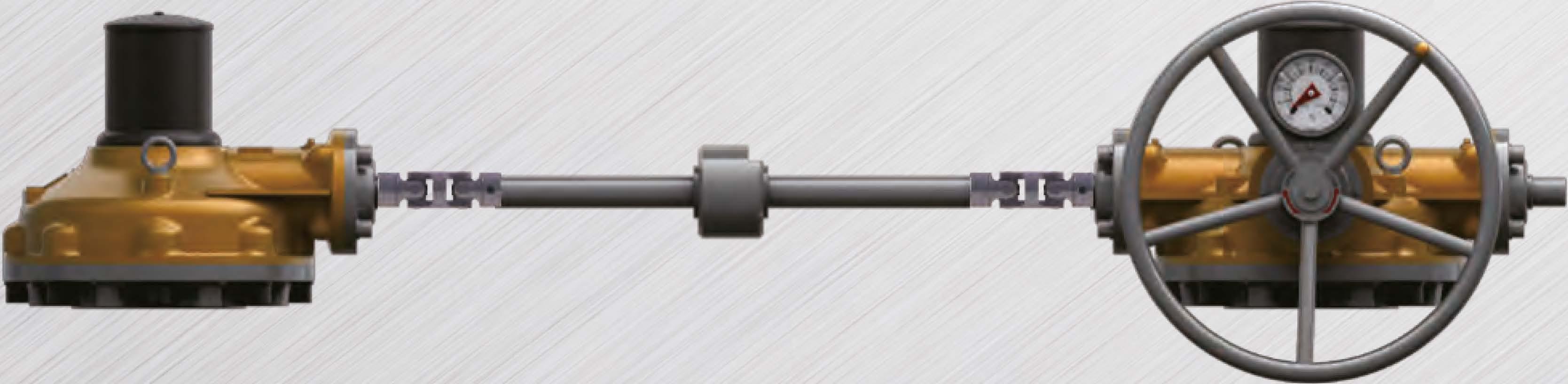
DualGearActuatorType (IYlanual Dial Indicator) >>> : Typical Arrangement for Two Spindles Application
1. This type is used for large size of sluice gates and designed for manufacturing type to operate efficiently using 2 spindles.
2. Local dial position indicator provides clear indication of gate position.
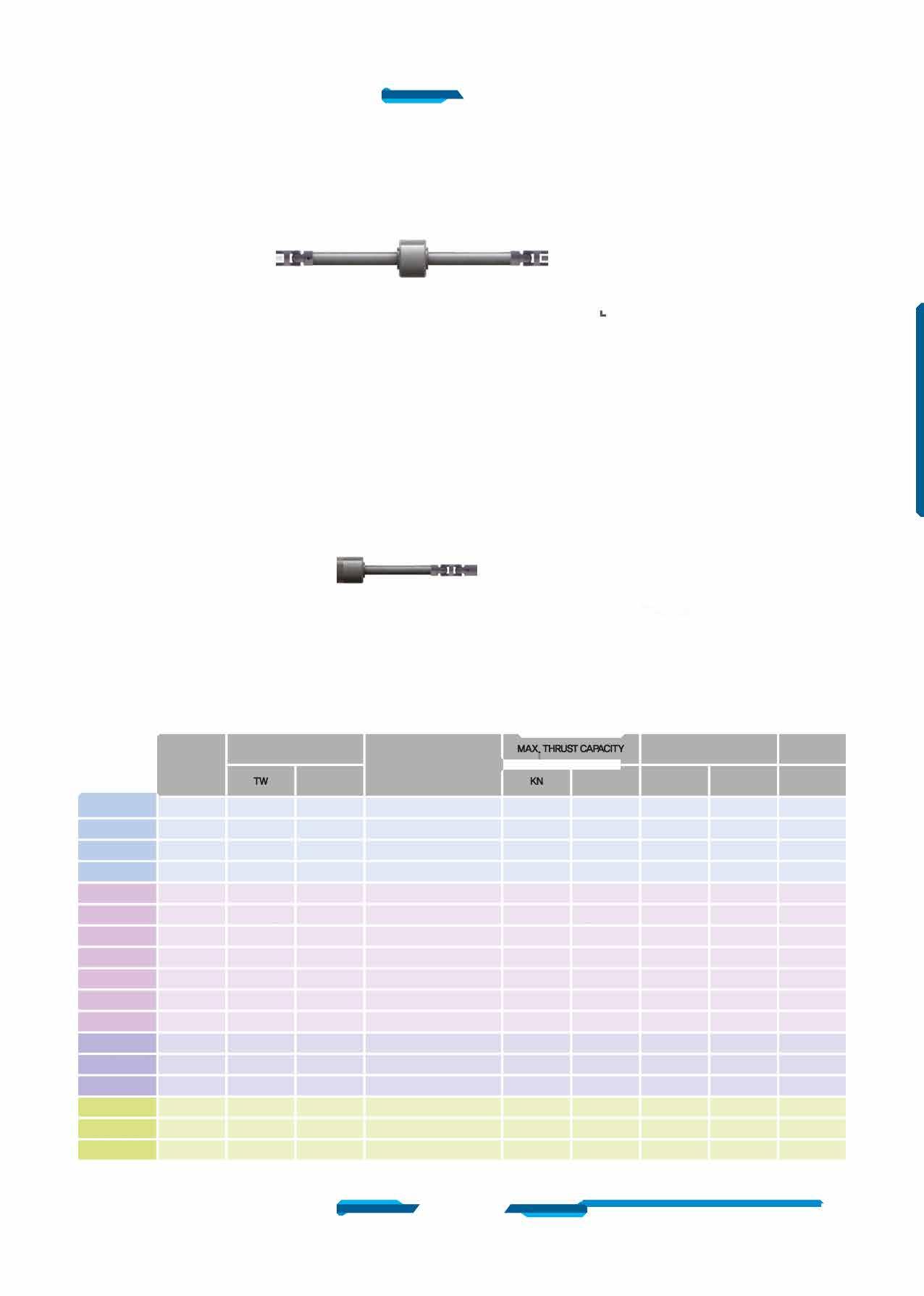
3. Samba can provide suitable interconnecting shafts and couplings if required. (Customer must state the center distance between the gate stems.)
DualGearActuatorType (Electric Actuators) >>>
: Typical Arrangement for Two Spindles Application
1. This type is used for large size of sluice gates and designed for manufacturing type to operate efficiently using 2 spindles.
2. Samba can provide suitable interconnecting shafts and couplings if required. (Customer must state the center distance between the gate stems.)


Sizeandcomponentspeciticationinthiscataloguearesubjecttochangewithoutpriornoticeforqualityimprovement. •IYlarkhasbeenchangedandupdated.
DualGearActuatorType (IYlanuaD >>> : Typical Arrangement for Two Spindles Application
1. This type is used for large size of sluice gates and designed for manufacturing type to operate efficiently using 2 spindles.
2. Samba can provide suitable interconnecting shafts and couplings if required. (Customer must state the center distance between the gate stems.)
DualGearActuatorType (Electric Actuators} >>> : Typical Arrangement for Two Spindles Application
1. This type is used for large size of sluice gates and designed for manufacturing type to operate efficiently using 2 spindles.
2. Samba can provide suitable interconnecting shafts and couplings if required. (Customer must state the center distance between the gate stems.)

*SB-V0W-1SD F-14 100 A
*SB-V1W-1SD F-16 130
SB-V2W-1SD F-16 140 (F-20)
SB-V3W-1SD F-25 200
SB-V35W-1SD F-30 230 B
SB-V4W-1SD F-35 260
SB-VSW-1SD F-40 300
SB-V55W-1SD F-40 300
SB-V6W-1SD F-40 300
SB-V7W-1SD F-48 370
SB-V75W-1SD C F-48 370
SB-V8W-1SD F-48 370
SB-V85W-1SD F-60 470
SB-V9W-1SD D F-60
*SB-V10W-1SD F-80

4-M1&-24
8-M16-24
8-M20-30 350 122
8-M30-45 410
8-M3&-55
8-M36-55
8-M36-55
12-M36-55
20-M36-55
DualGearActuatorType (Manual Dial Indicator) >>> : Typical Arrangement for Two Spindles Application
1. This type is used for large size of sluice gates and designed for manufacturing type to operate efficiently using 2 spindles.
2. Sambo can provide suitable interconnecting shafts and couplings if required. (Customer must state the center distance between the gate stems.)
DualGearActuatorType (Electric Actuators) >>> : Typical Arrangement for Two Spindles Application
1. This type is used for large size of sluice gates and designed for manufacturing type to operate efficiently using 2 spindles. 2. Sambo can provide suitable interconnecting shafts and couplings if

SB-V5W-1SD 80.31:1 110 95(28X16) F-25,F-30,F-35,F-40


1. Remove base plate socket head cap screws and base plate.
2. Remove Gasket
3. Use eye-bolts from housing and thread into tapped holes on end of the drive bushing.
4. Lift drive bushing with lower roller bearing.
5. Remove roller bearing from drive bushing.
6. Thread bushing as required.
7. Add grease as necessary.
B. Re-assembly in reverse order.
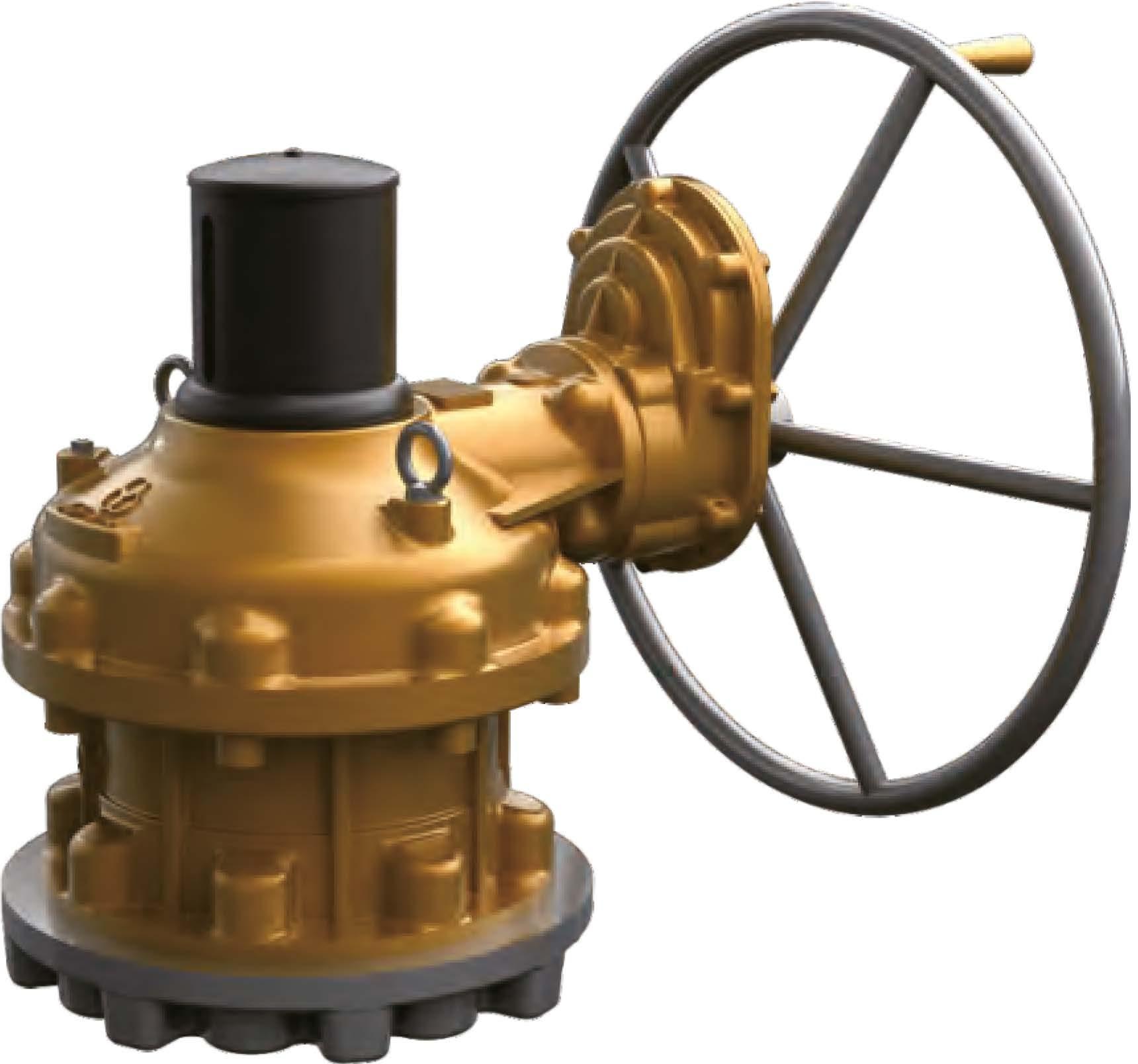
• This series suitable for extreme high thrust loads for use with Gate & Glove type valves. Also sluice gates and any other type requiring linear motion for high load thrust and torque applications.
• Bottom entry type stem nut. High tensile aluminum bronze material providing corrosion and abrasion resistance.
• Castings are Ductile Iron, class 65-45-12 providing high strength and impact resistance.
• Heavy duty roller bearings supporting both radial & axial thrust loads.
• Gears are IYlachine cut, heat treated and ground for optimum operation, Units are completely □-Ring Sealed suitable for temporary submergence to meet Ip67 class.
• IYlany options, such as hand wheels, chain wheels, stem covers, position dial indicators are available.


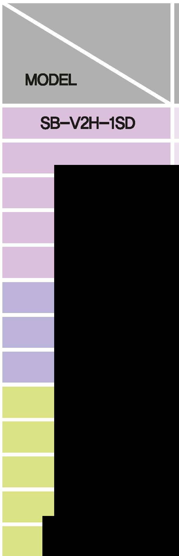
SB-V2H-1S F-25
SB-V3H-1S F-30
SB-V35H-1S B F-35
SB-V4H-1S
SB-VSH-1S F-40
SB-V55I-HS F-48
SB-V6H-1S C F-48
SB-V?H-1S F-48
SB-V75H-1S F-60
SB-V8H-1S F-60
SB-V85H-1S D F-60
1. Remove base plate socket head cap screws and base plate.
2. Remove Gasket
3. Use eye-bolts from housing and thread into tapped holes on end of the drive bushing.
4. Lift drive bushing with lower roller bearing.
5. Remove roller bearing from drive bushing.
6. Thread bushing as required.
7. Add grease as necessary.
B. Re-assembly in reverse order.
• This series suitable for extreme high thrust loads for use with Gate & Glove type valves. Also sluice gates and any other type requiring linear motion for high load thrust and torque applications.
• Bottom entry type stem nut. High tensile aluminum bronze material providing corrosion and abrasion resistance.
• Castings are Ductile Iron, class 65-45-12 providing high strength and impact resistance.
• Heavy duty roller bearings supporting both radial & axial thrust loads.
• Gears are IYlachine cut, heat treated and ground for optimum operation, Units are completely □-Ring Sealed suitable for temporary submergence to meet Ip67 class.
• IYlany options, such as hand wheels, chain wheels, stem covers, position dial indicators are available. Global .eader �����1}}�I1L:�a/ues


10.13:16555(16X10)(F-20),F-251080242800
SB-V3H-1S 12.66:18070(20X12)F-25,F-301710384400
SB-V35H-1S 16.5:19585(22X14)2450550800 F--25,F-30,F-35
SB-V4H-1S 18:111095(25X14)2900651900
SB-V5H-1S 22,94:1130115(32X18)F-30,F-35,F---403500786800
SB-V55H-1S 24,5:1140120(32X18)F--35,F-40,F---484200944197
SB-V6H-1S 28:1150130(36X20)F--35,F-40,F---4847001056600
SB-V7H-1S 30.22:1170150(40X22)F---4852001169000
SB-V75H-1S 40:1190170(40X22)F--48,F--6068001528701
SB-VSH-1S 40:1215185(45X25)F-48,F--6076501719800
SB-V85H-1S 40:1225195(45X25)F-48,F--6091002045760
•SB-V9H-1S 40:1240215(50X28)F--60,F--8094002113200
*
SB-V10H-1S 40:1270240(56X32)F--60,F--80115002585300


SB-V21+-1ST F-25
SB-V3+-1Sf F-30
SB-V3!i-l-1Sf B F-35
SB-V4H-1ST
SB-V!it-1Sf F-40 F--48

SB-V&+-1ST C F-48
SB-V71+-1ST F-48
SB-V75H-1ST F-60
SB-va+-1ST F-60
SB-V85H-1ST D F-60
*SB-V9+-1ST F--80
*SB-V10+-1Sf F--80
CW-CLOSE
CW-CLOSE
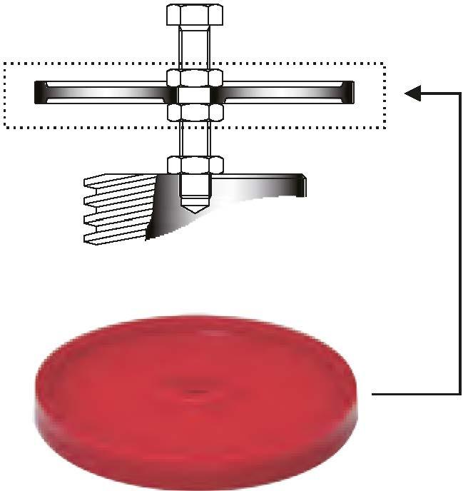
Disassembly flow chart of thrust bush for processing of stem thread
1. Remove base plate socket head cap screws and base plate.
2. Remove Gasket
3. Use eye-bolts from housing and thread into tapped holes on end of the drive bushing.
4. Lift drive bushing with lower roller bearing.
5. Remove roller bearing from drive bushing.
6. Thread bushing as required.
7. Add grease as necessary.
8. Re-assembly in reverse order.
A. Primary Input Shaft (High Speed Input Shaft) Allow for less turns after valve has been unseating.
B. Second Input Shaft (Low Speed Input Shaft) Provides maximum mechanical advantage for seating and unseating of valves.
• This series suitable for extreme high thrust loads for use with Gate & Glove type valves. Also sluice gates and any other type requiring linear motion for high load thrust and torque applications.
• Bottom entry type stem nut. High tensile aluminum bronze material providing corrosion and abrasion resistance.
• Castings are Ductile Iron, class 65-45-12 providing high strength and impact resistance.
• Heavy duty roller bearings supporting both radial & axial thrust loads.
• Gears are IYlachine cut, heat treated and ground for optimum operation, Units are completely □-Ring Sealed suitable for temporary submergence to meet Ip67 class.
• IYlany options, such as hand wheels, chain wheels, stem covers,position dial indicators are available.


SS-V2tHSD F-25 200
SS-V3H-1SD F-30 230
SS-V35H-1SD B F-35 260
SS-V4H-1SD
SS-V5H-1SD F--40 300
SS-V55tHSD F--48 370
SS-V6tHSD C F--48 370
SS-V7tHSD F--48
SS-V75H-1SD F-60 470
SS-V8H-1SD F-60 470
SS-V85H-1SD D F-60
*SS-V9H-1SD F-80 670
* SS-V10H-1SD F-80


1. Remove base plate socket head cap screws and base plate.
2. Remove Gasket
3. Use eye-bolts from housing and thread into tapped holes on end of the drive bushing.
4. Lift drive bushing with lower roller bearing.
5. Remove roller bearing from drive bushing.
6. Thread bushing as required.
7. Add grease as necessary.
B. Re-assembly in reverse order.
• This series suitable for extreme high thrust loads for use with Gate & Glove type valves. Also sluice gates and any other type requiring linear motion for high load thrust and torque applications.
• Bottom entry type stem nut. High tensile aluminum bronze material providing corrosion and abrasion resistance.
• Castings are Ductile Iron, class 65-45-12 providing high strength and impact resistance.
• Heavy duty roller bearings supporting both radial & axial thrust loads.
• Gears are IYlachine cut, heat treated and ground for optimum operation, Units are completely □-Ring Sealed suitable for temporary submergence to meet Ip67 class.
• IYlany options, such as hand wheels, chain wheels, stem covers, position dial indicators are available.
Global .eader

25.67:16555(16X10)(F-20),F--251080242800
SB--V3H-1SD 32.08:18070(20X12)F-25,F-301710384400
SB--V35H-1SD 49.5:19585(22X14)2450550800 F--25,F-30,F-35
SB--V4H-1SD 54:111095(25X14)2900651900
SB--VSH-1SD 80.31:1130115(32X18)F--30,F--35,F---403500786800
SB--V551-HSD 85_75:1140120(32X18)F--35,F-40,F---484200944197
SB--V61-HSD 112:1150130(36X20)F--35,F-40,F---4847001056600
SB--V71-HSD 120.88:1170150(40X22)F---4852001169000
SB--V751-HSD 200:1190170(40X22)F--48,F--6068001528701
SB--VSH-1SD 200:1215185(45X25)F--48,F--6076501719800
SB--V851--HSD 200:1225195(45X25)F--48,F--6091002045760
*SB-V91--HSD 200:1240215(50X28)F--60,F---8094002113200
*SB-Vl0H-1SD 200:1270240(56X32)F--60,F---80115002585300
42778 1055


SB-V21-HSDT F-25 200
SB-V3H-1SDT F-30 230
SB-V35H-1SDT B F-35 260
SB-V4H-1SDT
SB-V51·-HSDT F-40 300
SB-V55H-1SDT F-48 370
SB-V6H-1SDT C F--48 370
SB-V7H-1SDT F--48
SB-V75H-1SDT F--60 470
SB-V8H-1SDT F--60 470
SB-V85H-1SDT D F--60
Size and component specitication in this catalogue are subject to change without prior notice for quality improvement.
• IYlark has been changed and updated.
CW-CLOSE
1. Remove base plate socket head cap screws and base plate.
2. Remove Gasket
3. Use eye-bolts from housing and thread into tapped holes on end of the drive bushing.
4. Lift drive bushing with lower roller bearing.
5. Remove roller bearing from drive bushing.
6. Thread bushing as required.
7. Add grease as necessary.
B. Re-assembly in reverse order.
A. Prima� Input Shaft (High Speed Input Shaft)
Allow for less turns after valve has been unseating.
B.Second Input Shaft (Low Speed Input Shaft)
Provides maximum mechanical advantage for seating and unseating of valves.
• This series suitable for extreme high thrust loads for use with Gate & Glove type valves. Also sluice gates and any other type requiring linear motion for high load thrust and torque applications.
• Bottom entry type stem nut. High tensile aluminum bronze material providing corrosion and abrasion resistance.
• Castings are Ductile Iron, class 65-45-12 providing high strength and impact resistance.
• Heavy duty roller bearings supporting both radial & axial thrust loads.
• Gears are IYlachine cut, heat treated and ground for optimum operation, Units are completely □-Ring Sealed suitable for temporary submergence to meet Ip67 class.
• IYlany options, such as hand wheels, chain wheels, stem covers, position dial indicators are available.


SB-V2H-28 F-25
SB-V3H-2B F-30
SB-V35H-2B B F-35
SB-V4H-2B
SB-V5H-2B F-40
SB-V55H-2B F--48
SB-VSH-28 C F--48
SB-V71+-28 F--48
*SB-V75H-28 F-60
SB-VSH-28 F-60
SB-V85H-28 D F-60
F--80
F--80
1. Remove base plate socket head cap screws and base plate.
2. Remove Gasket
3. Use eye-bolts from housing and thread into tapped holes on end of the drive bushing.
4. Lift drive bushing with lower roller bearing.
5. Remove roller bearing from drive bushing.
6. Thread bushing as required.
7. Add grease as necessary.
B. Re-assembly in reverse order.
• This series suitable for extreme high thrust loads for use with Gate & Glove type valves. Also sluice gates and any other type requiring linear motion for high load thrust and torque applications.
• Bottom entry type stem nut. High tensile aluminum bronze material providing corrosion and abrasion resistance.
• Castings are Ductile Iron, class 65-45-12 providing high strength and impact resistance.
• Heavy duty roller bearings supporting both radial & axial thrust loads.
• Gears are IYlachine cut, heat treated and ground for optimum operation, Units are completely □-Ring Sealed suitable for temporary submergence to meet Ip67 class.
• IYlany options, such as hand wheels, chain wheels, stem covers, position dial indicators are available.
.eader


1. Remove base plate socket head cap screws and base plate.
2. Remove Gasket
3. Use eye-bolts from housing and thread into tapped holes on end of the drive bushing.
4. Lift drive bushing with lower roller bearing.
5. Remove roller bearing from drive bushing.
6. Thread bushing as required.
7. Add grease as necessary.
B. Re-assembly in reverse order.
• This series suitable for extreme high thrust loads for use with Gate & Glove type valves. Also sluice gates and any other type requiring linear motion for high load thrust and torque applications.
• Bottom entry type stem nut. High tensile aluminum bronze material providing corrosion and abrasion resistance.
• Castings are Ductile Iron, class 65-45-12 providing high strength and impact resistance.
• Heavy duty roller bearings supporting both radial & axial thrust loads.
• Gears are IYlachine cut, heat treated and ground for optimum operation, Units are completely □-Ring Sealed suitable for temporary submergence to meet Ip67 class.
• IYlany options, such as hand wheels, chain wheels, stem covers, position dial indicators are available.


High Load Thrust & Torque Horizontal Input with Single Reduction Gear Attachment
Dimension

SB-V2HW-1S F-25
SB-V3HW-1S F-30
SB-V351fN-1S B F-35
SB-V4HW-1S
SB-VSHW-1S F-40 F-48

SB-VSHW-1S C F-48
SB-V7HW-1S F-48
SB-V75HW-1S F-60
SB-V8HW-1S
SB-V85HW-1S D F-60
*SB-V9HW-1S F--80
*SB-V10HW-1S F--80
Size and component specitication in this catalogue are subject to change without prior notice for quality improvement.
IYlark has been changed and updated.
1. Remove base plate socket head cap screws and base plate.
2. Remove Gasket
3. Use eye-bolts from housing and thread into tapped holes on end of the drive bushing.
4. Lift drive bushing with lower roller bearing.
5. Remove roller bearing from drive bushing.
6. Thread bushing as required.
7. Add grease as necessary.
B. Re-assembly in reverse order.
• This series suitable for extreme high thrust loads for use with Gate & Glove type valves. Also sluice gates and any other type requiring linear motion for high load thrust and torque applications.
• Bottom entry type stem nut. High tensile aluminum bronze material providing corrosion and abrasion resistance.
• Castings are Ductile Iron, class 65-45-12 providing high strength and impact resistance.
• Heavy duty roller bearings supporting both radial & axial thrust loads.
• Gears are IYlachine cut, heat treated and ground for optimum operation, Units are completely □-Ring Sealed suitable for temporary submergence to meet Ip67 class.
• IYlany options, such as hand wheels, chain wheels, stem covers, position dial indicators are available.
SB-V7HW-1S 30.22:1 170 150(40X22) F--48
SB-V75H'W-1S 40:1


SB-V2H\N-1SD
SB-V3HW-1SD
SB-V35HW-1SD B
SB-V4HW-1SD
SB-VSHW-1SD
SB-V55HW-1SD
SB-V6HW-1SD C
SB-V7HW-1SD
SB-V75HW-1SD
SB-V8HW-1SD
SB-V85HW-1SD D
*SB-V9HW-1SD
*SB-V10HW-1SD
1. Remove base plate socket head cap screws and base plate.
2. Remove Gasket
3. Use eye-bolts from housing and thread into tapped holes on end of the drive bushing.
4. Lift drive bushing with lower roller bearing.
5. Remove roller bearing from drive bushing.
6. Thread bushing as required.
7. Add grease as necessary.
B. Re-assembly in reverse order.
• This series suitable for extreme high thrust loads for use with Gate & Glove type valves. Also sluice gates and any other type requiring linear motion for high load thrust and torque applications.
• Bottom entry type stem nut. High tensile aluminum bronze material providing corrosion and abrasion resistance.
• Castings are Ductile Iron, class 65-45-12 providing high strength and impact resistance.
• Heavy duty roller bearings supporting both radial & axial thrust loads.
• Gears are IYlachine cut, heat treated and ground for optimum operation, Units are completely □-Ring Sealed suitable for temporary submergence to meet Ip67 class.
• IYlany options, such as hand wheels, chain wheels, stem covers, position dial indicators are available.
SB-V55HW-1SD 85_75:1 140 120(32X18) F-35,F-40,F-48 4200 944197
SB-V6HVv-1SD 112:1 150 130(36X20) F-35,F-40,F-48 4700 1056600
SB-V7HVv-1SD 120.88:1 170 150(40X22) F--48 5200 1169000
SB-V75HW-1SD

SB-VSHW-28
SB-V55HW-2B
SB-V6HW-28
SB-V7HW-28
SB-VBHW-28
SB-V85HW-28
1. Remove base plate socket head cap screws and base plate.
2. Remove Gasket
3. Use eye-bolts from housing and thread into tapped holes on end of the drive bushing.
4. Lift drive bushing with lower roller bearing.
5. Remove roller bearing from drive bushing.
6. Thread bushing as required.
7. Add grease as necessary.
B. Re-assembly in reverse order.
• This series suitable for extreme high thrust loads for use with Gate & Glove type valves. Also sluice gates and any other type requiring linear motion for high load thrust and torque applications.
• Bottom entry type stem nut. High tensile aluminum bronze material providing corrosion and abrasion resistance.
• Castings are Ductile Iron, class 65-45-12 providing high strength and impact resistance.
• Heavy duty roller bearings supporting both radial & axial thrust loads.
• Gears are IYlachine cut, heat treated and ground for optimum operation, Units are completely □-Ring Sealed suitable for temporary submergence to meet Ip67 class.
• IYlany options, such as hand wheels, chain wheels, stem covers, position dial indicators are available.


SB-V6HW-2B 35:1 150 130(36X20) F-35,F-40,F-48 4700 1056600
SB-V7HW-2B 37.77:1 170 150(40X22) F---48 5200 1169000
*SB-V75HW-2B 44:1 190 170(40X22) F-48,F--60
Contact your local CDC sales representatives:
Serving OH, MI, W.PA, WV, E.KY, VA

143 S.Thomas Rd. Tallmadge, OH 44278
Tel: 330-253-4800
Email: sales@portersvilleprd.com
7707 Cole Lane Midland MI 48642
Tel: 586-764-4336
Email: sales@portersvilleprd.com
www.portersvilleprd.com
2680 New Butler Rd. New Castle, PA 16101
Tel: 724-368-8725
Email: sales@portersvilleprd.com
700 Southlake Blvd. North Chesterfield VA 23236
Tel: 804-593-2384
Email: sales@portersvilleprd.com

1500 E. Burnett St. Signal Hill, CA 90755
Tel: 562-424-8108
Email: Sales@BV-BM.com
www.bv-bm.com
403 Technology Dr South Point, OH 45680
Tel: 740-377-0012
Email: sales@portersvilleprd.com

3800 Fruitvale Avenue Bakersfield, 93308
Tel: 661-589-6801
Email: Sales@BV-BM.com
3195 Park Road, Benicia, CA 94510
Tel: 707-590-6688
Email: Sales@BV-BM.com