


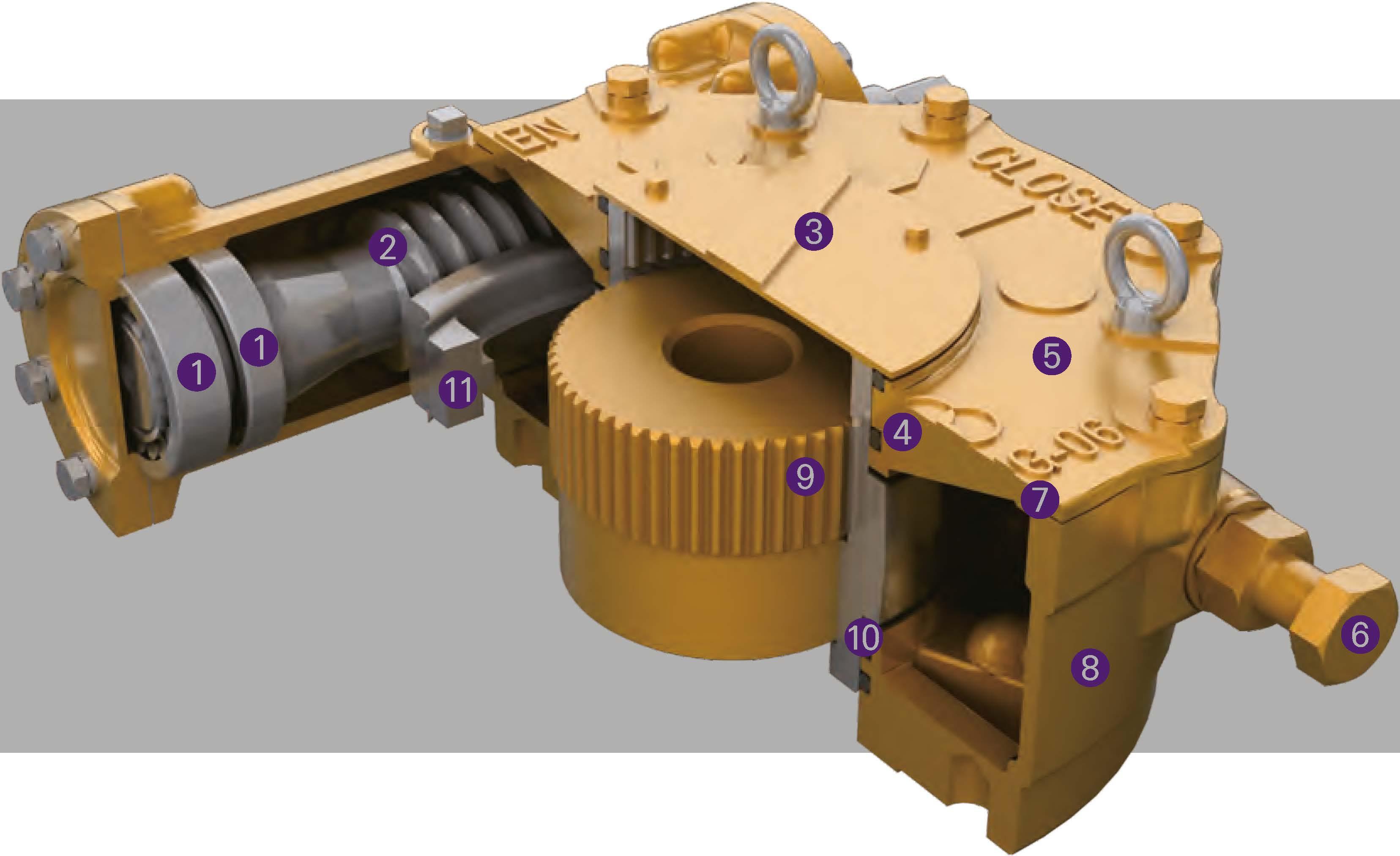
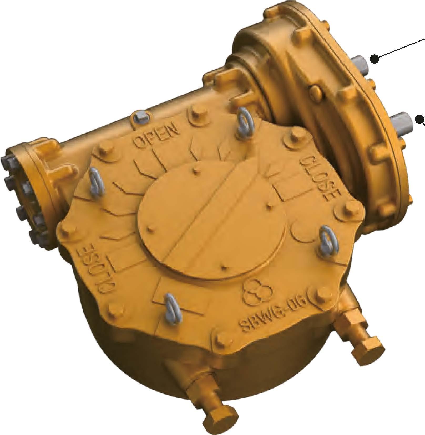
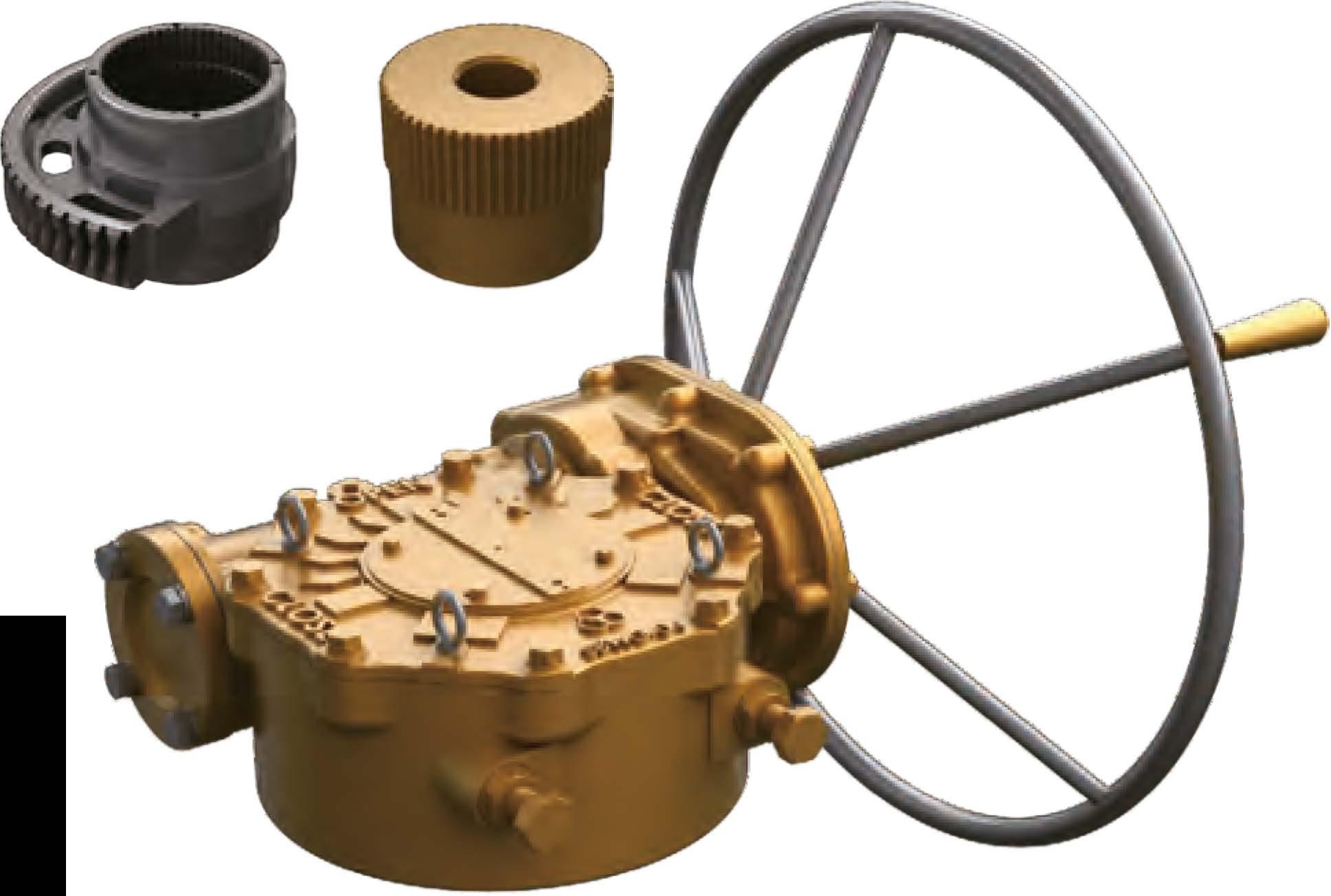
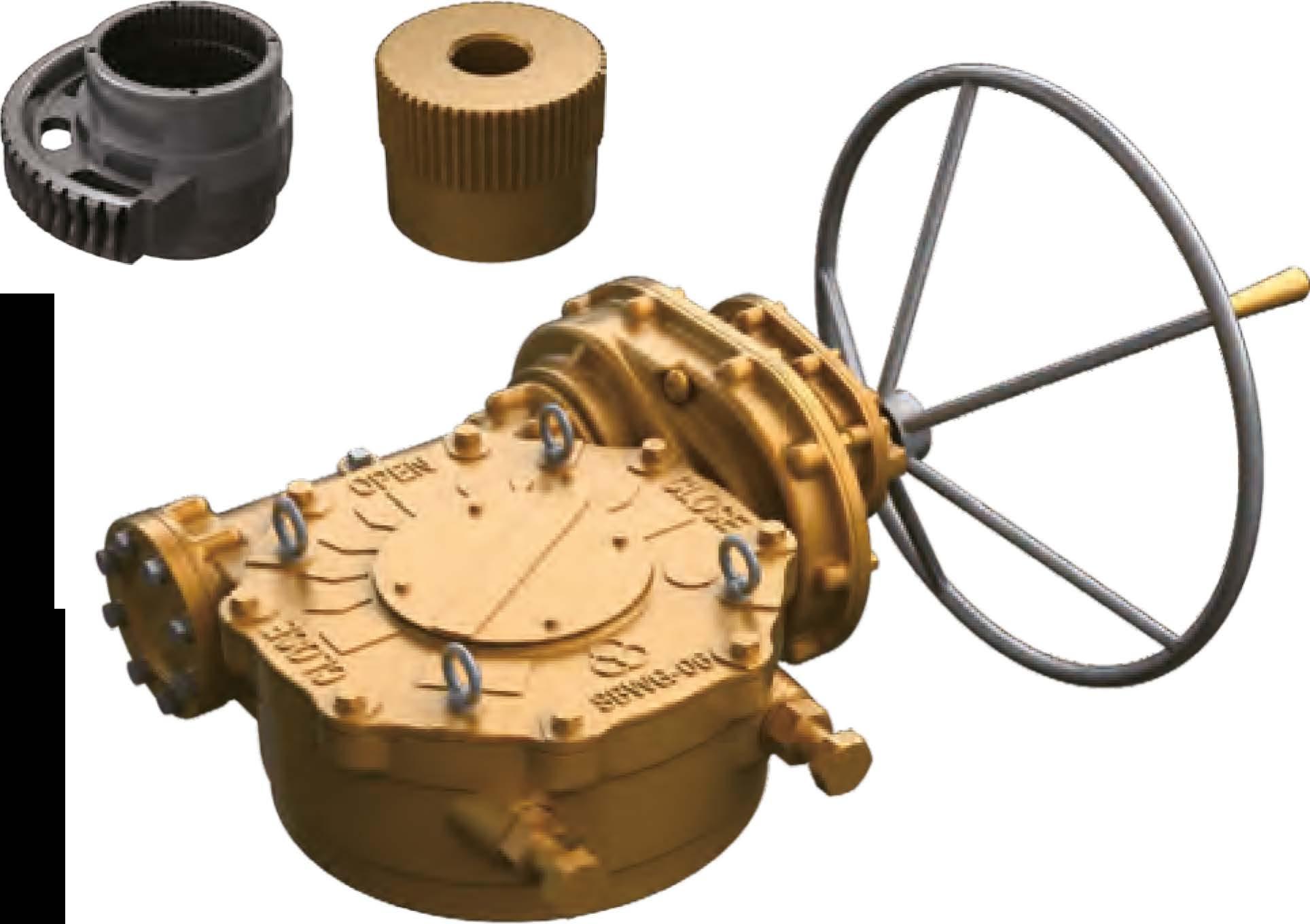
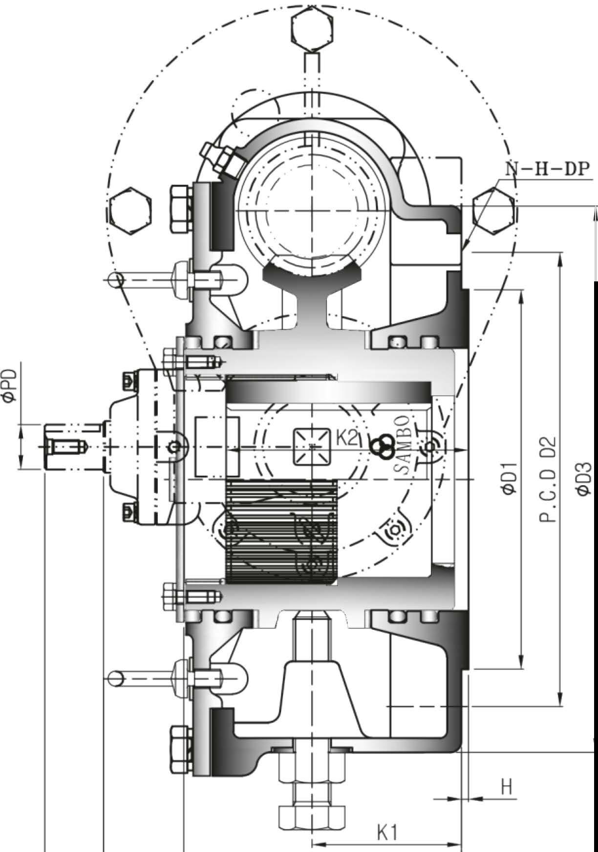
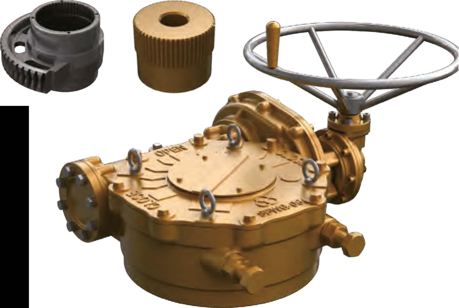
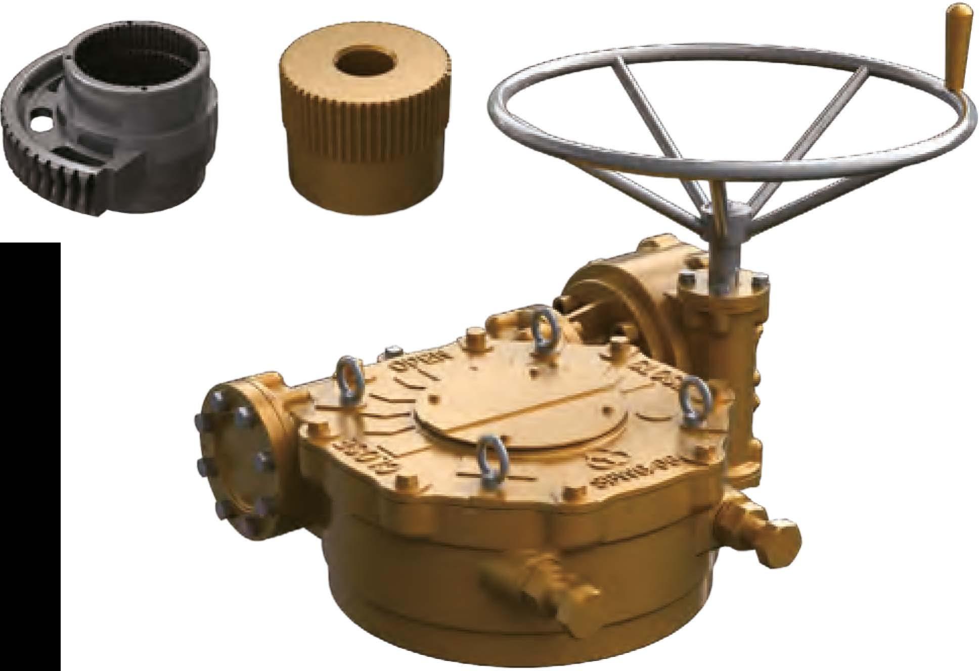
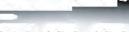
CD Tapered Roller & Ball Bearings
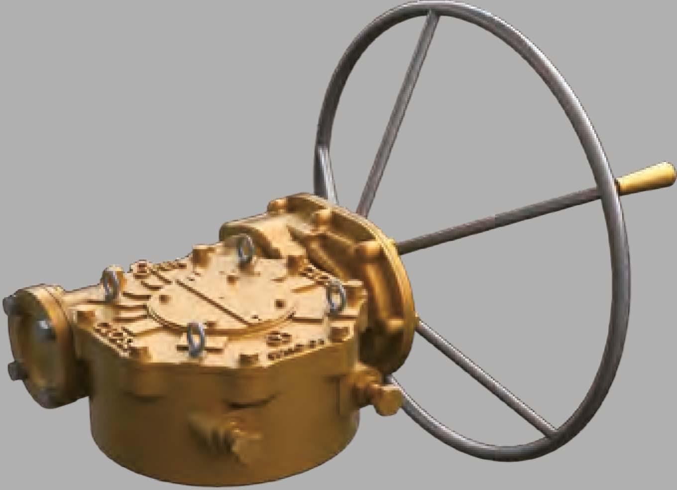
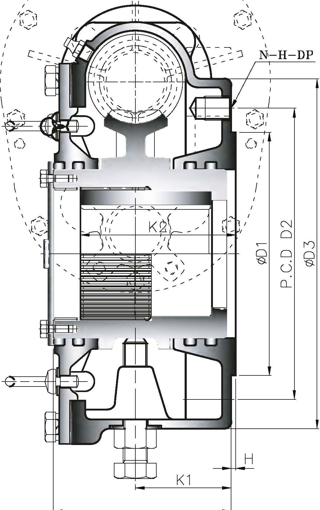
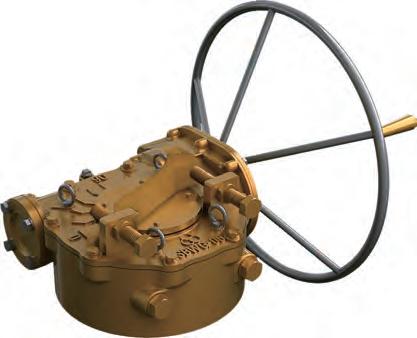
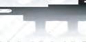
The Worm is supported on tapered roller bearings which support both the axial and radial forces generated by the gearings.They have excellent load bearing capacity.
@Worm
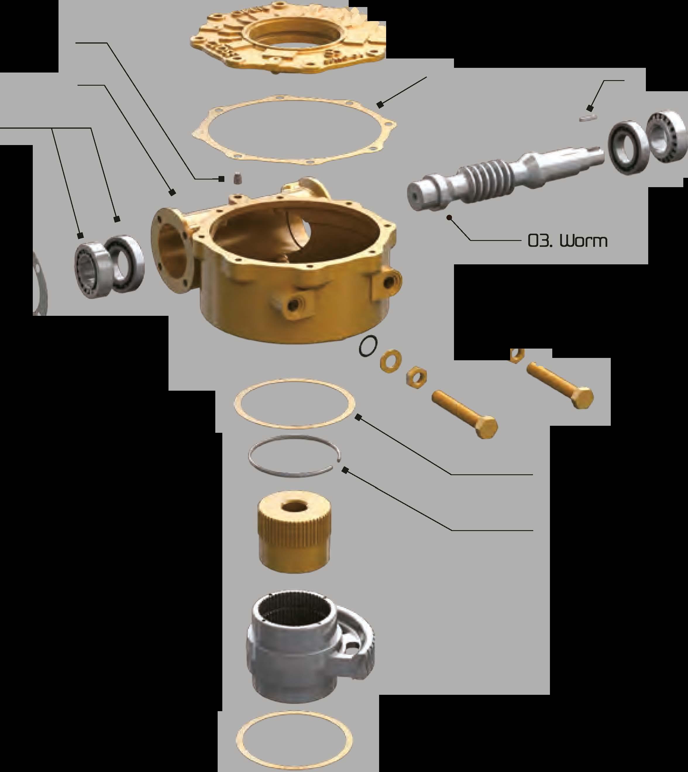
1045 heat treated steel, with ground and polished worm threads. Precision cutting of the threads provides minimum backlash between the worm gearand worm.
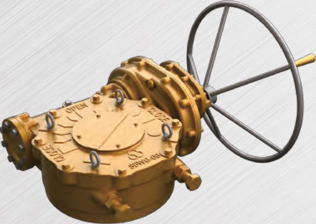
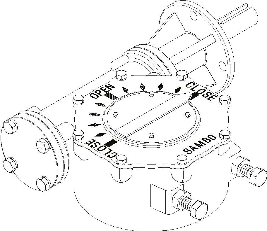
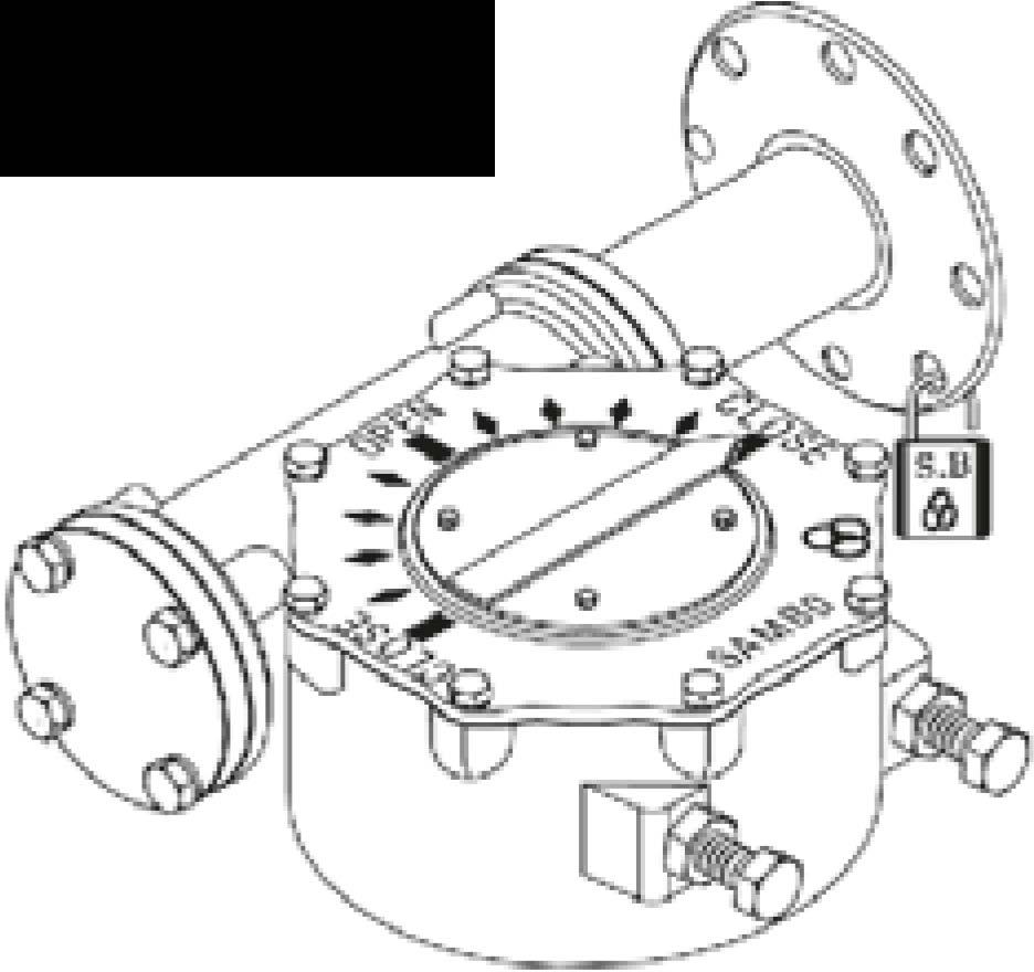
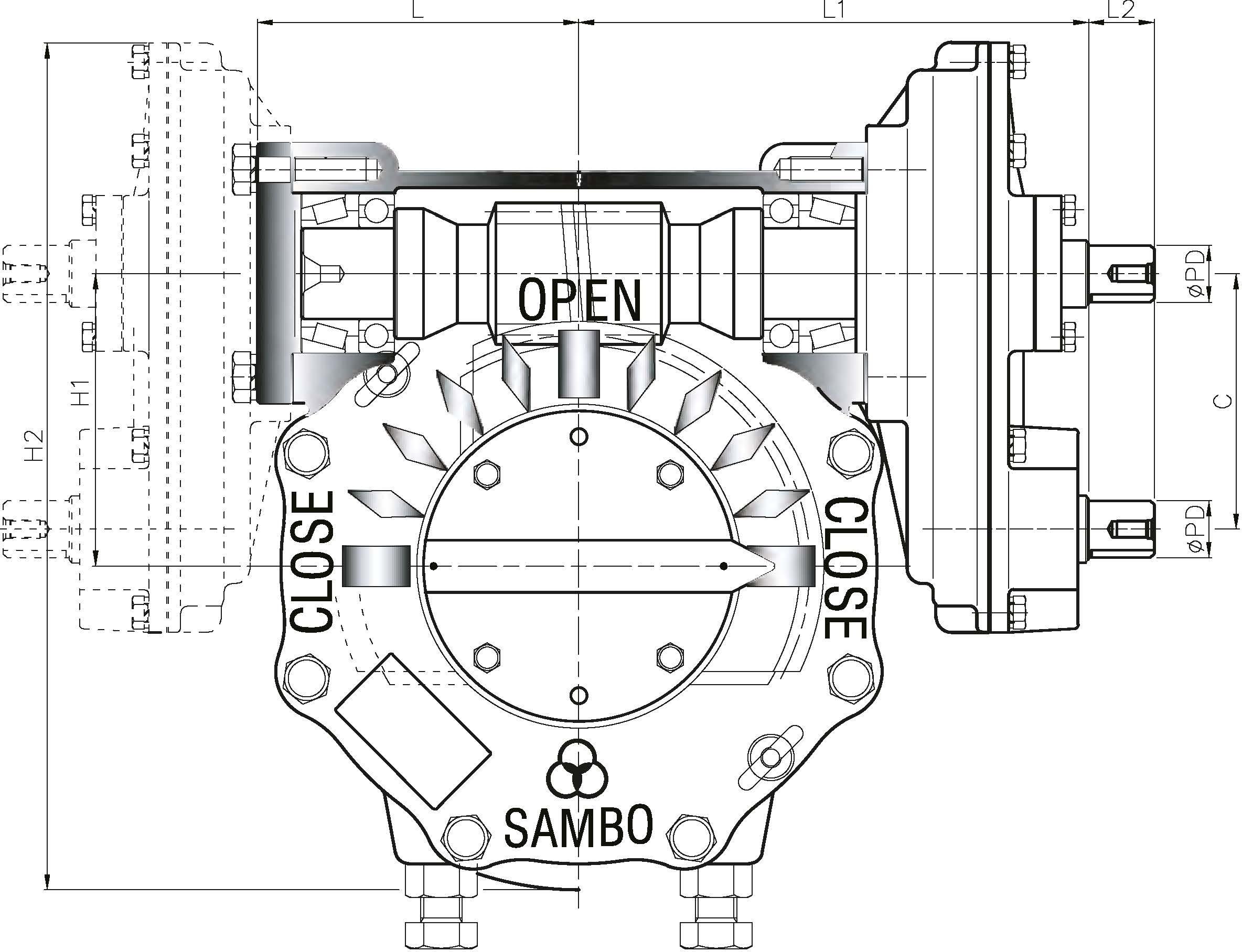
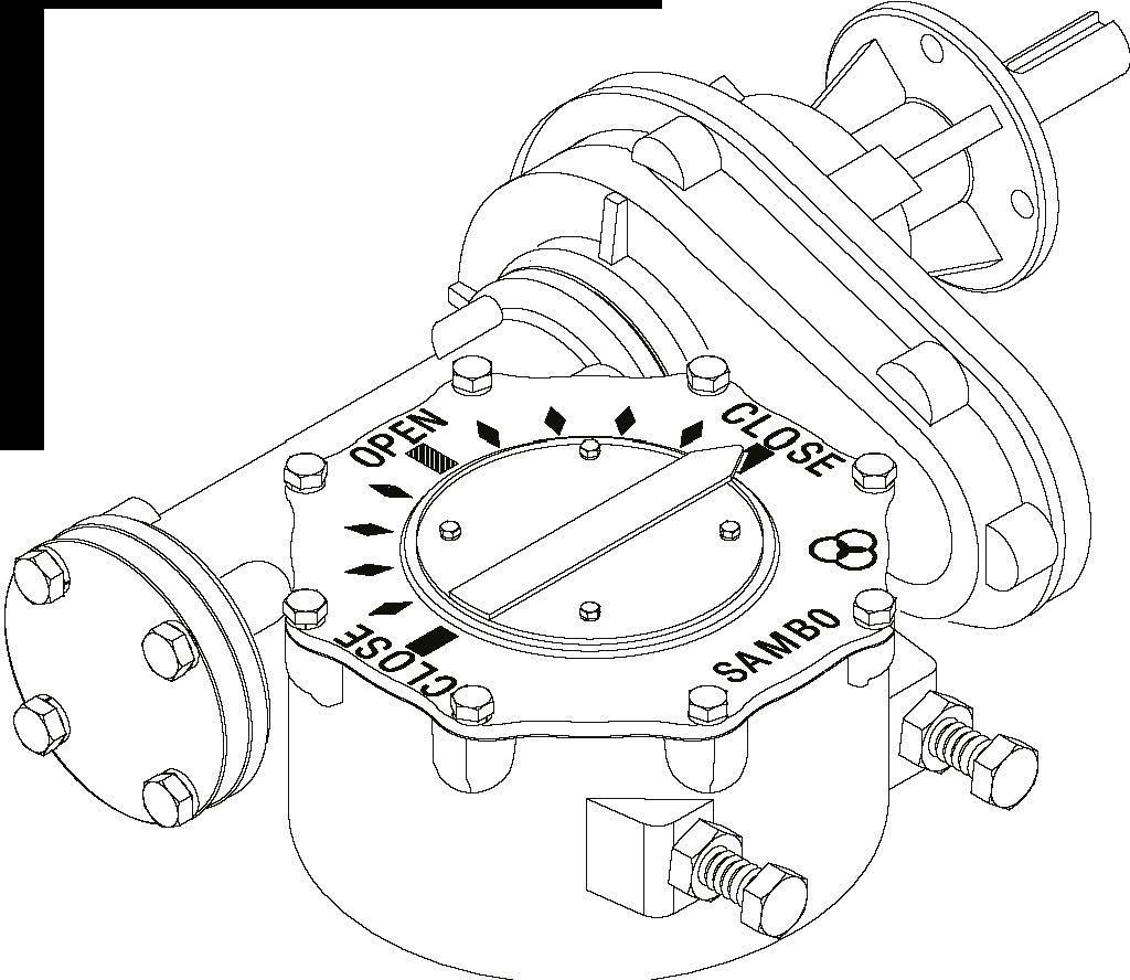
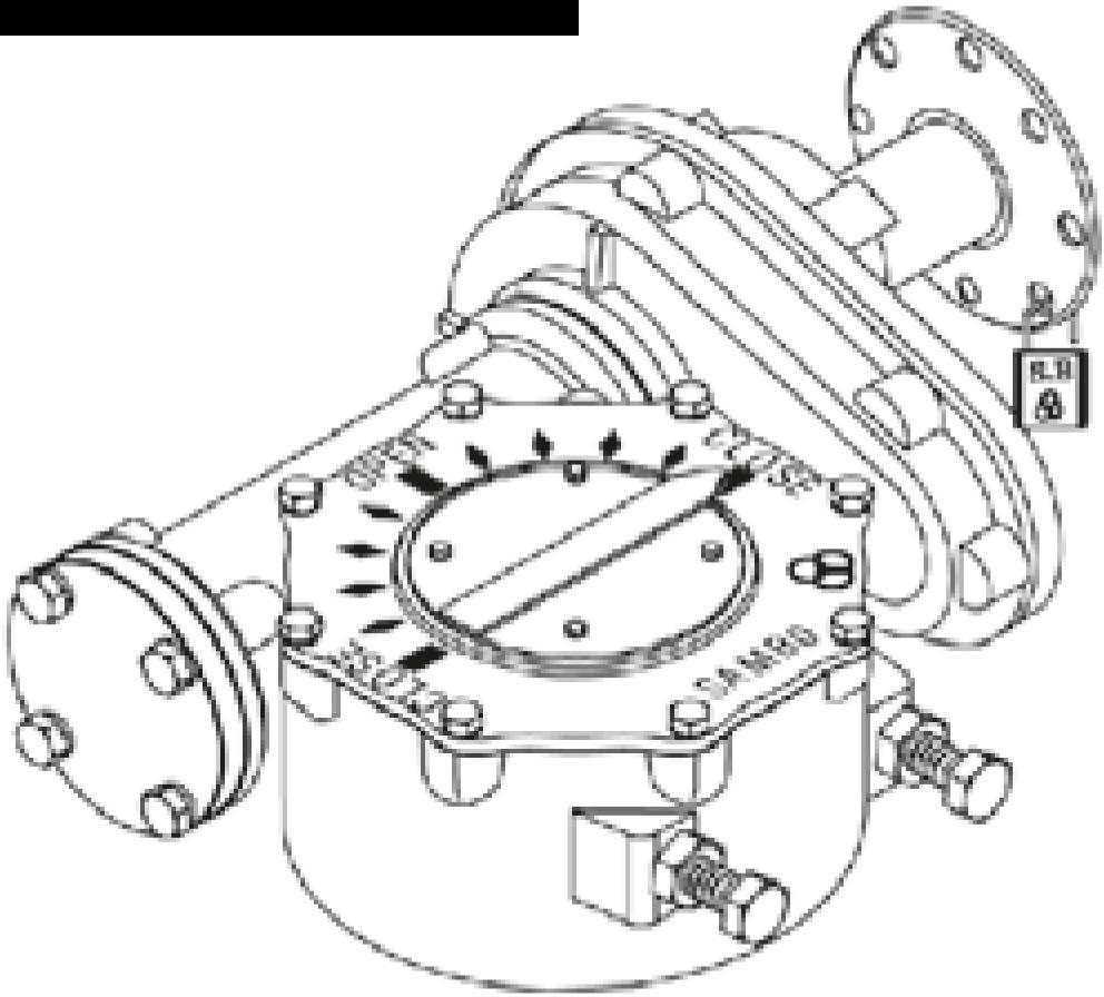
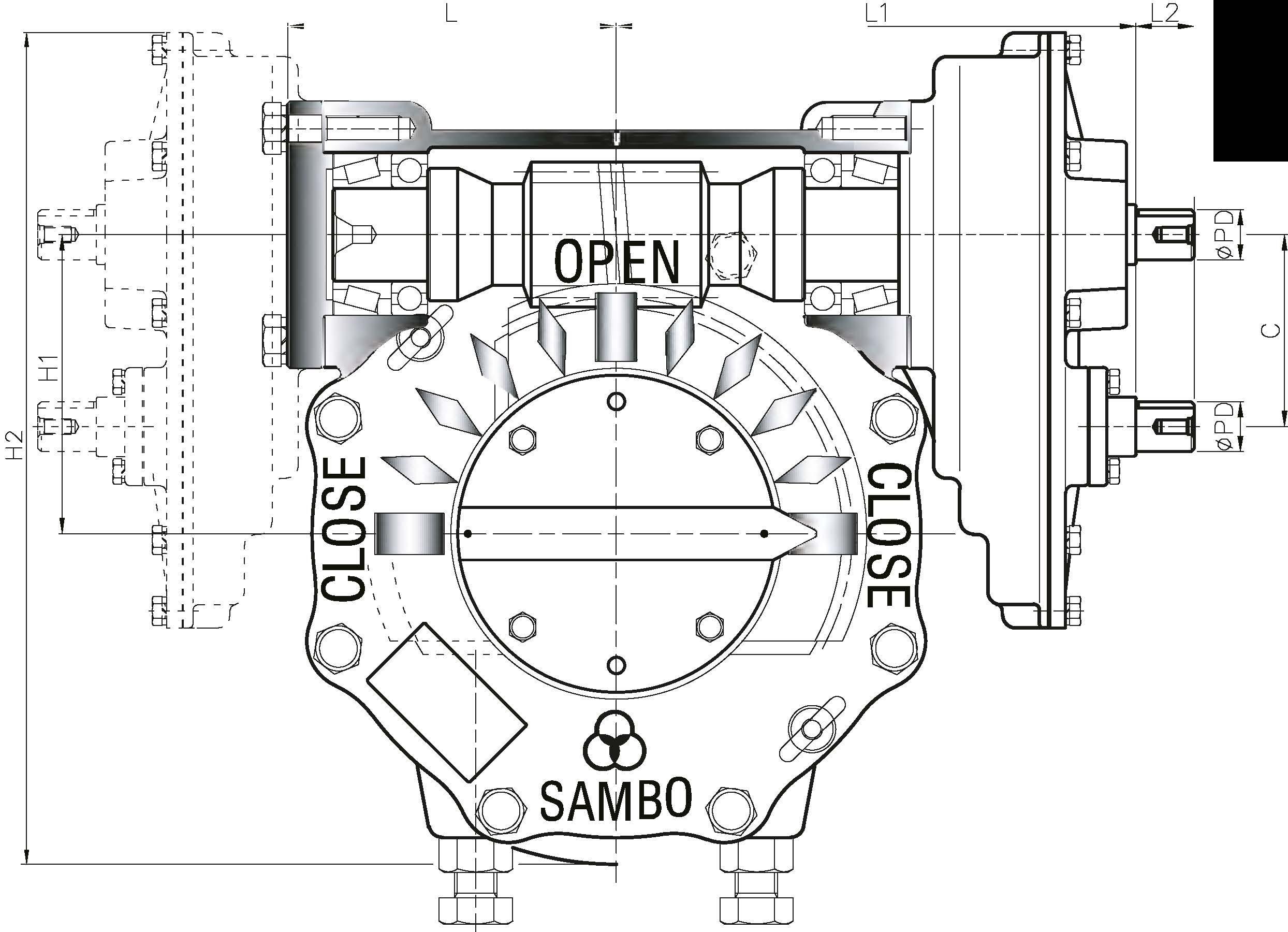
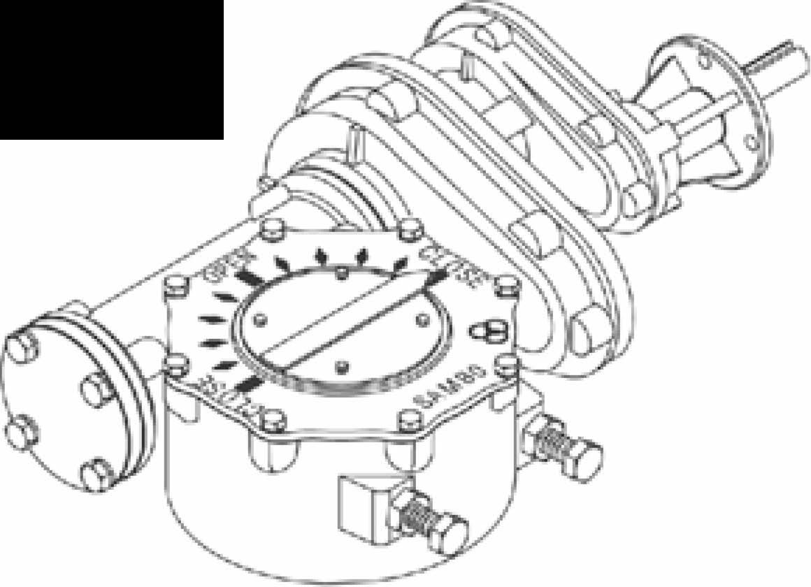
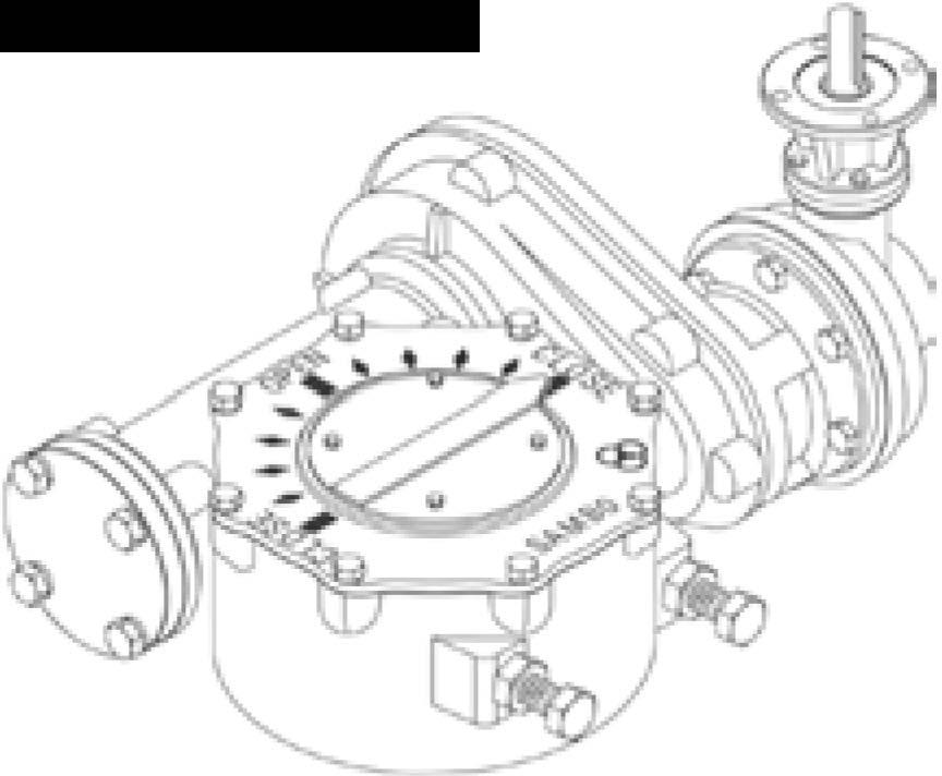
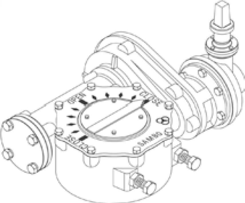
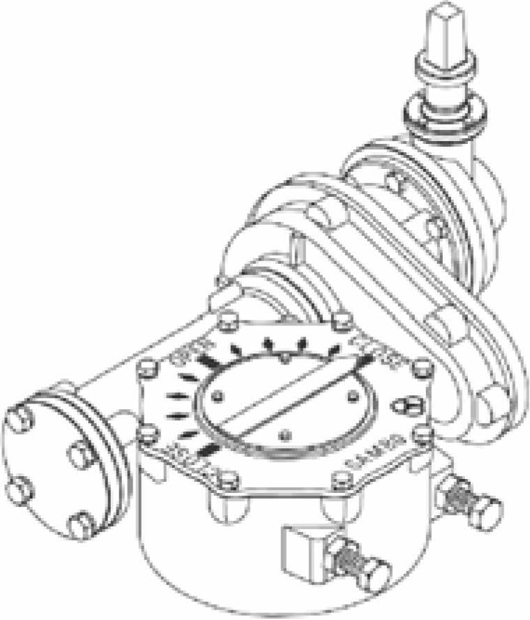
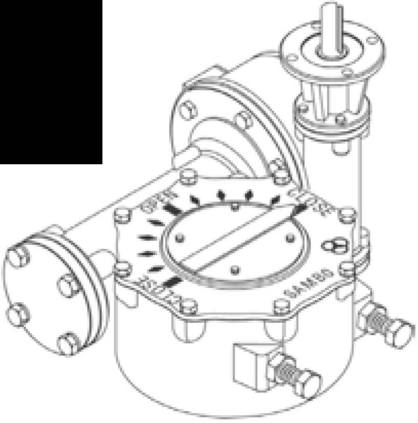
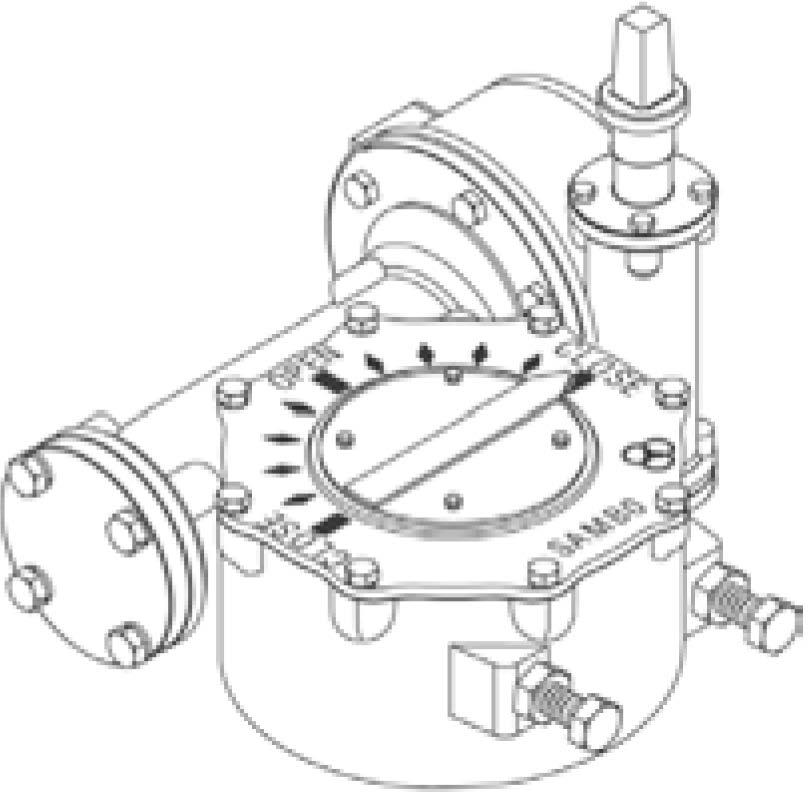
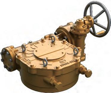
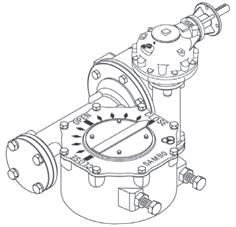
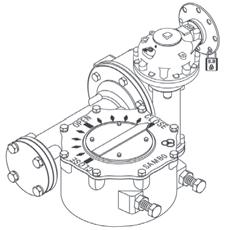
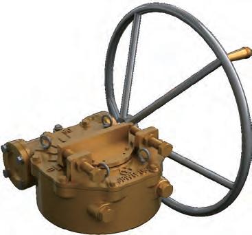
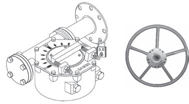
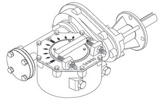
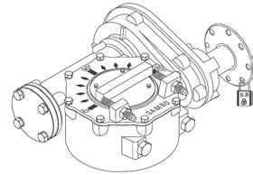
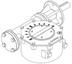
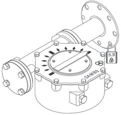
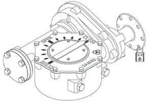
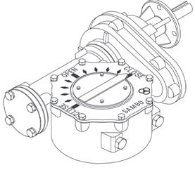
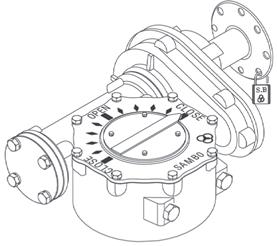
® Indicator Plate
Pointer provides positive position indication. The pointer can easily be re-positioned if required.
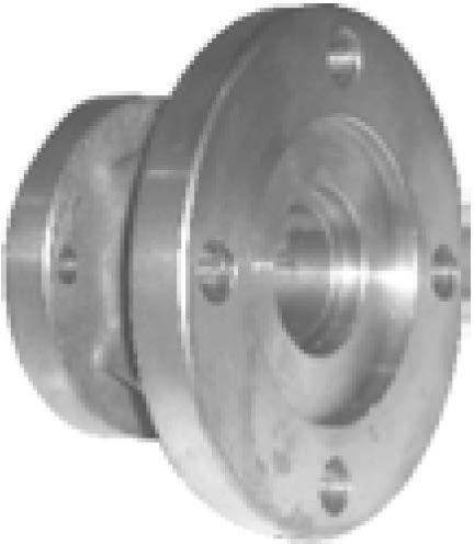
@ Sealing
The drive sleeve is supplied with a oil seal at the top and large cross-section a-ring at the bottom. This sealing method allows the units to be rated for submersible service to Ip57 standards.
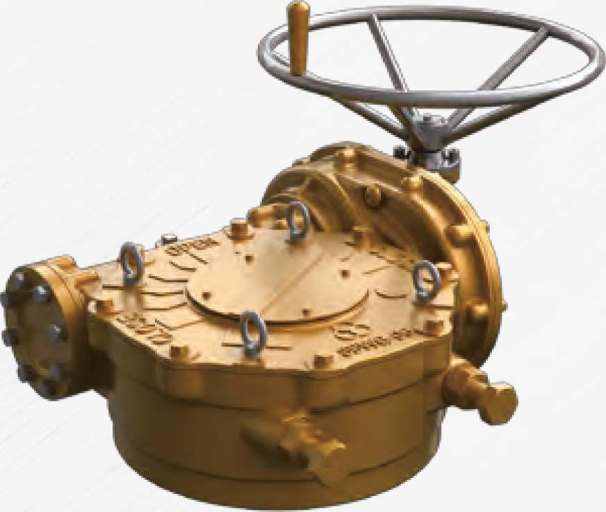
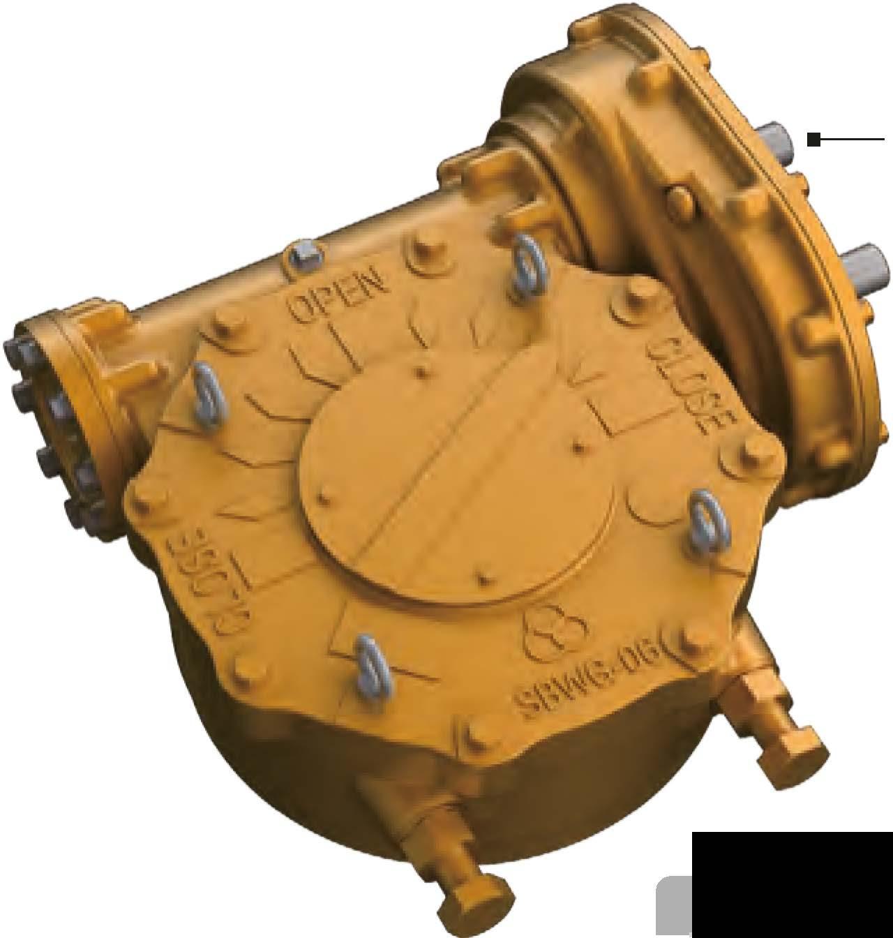
® Cover
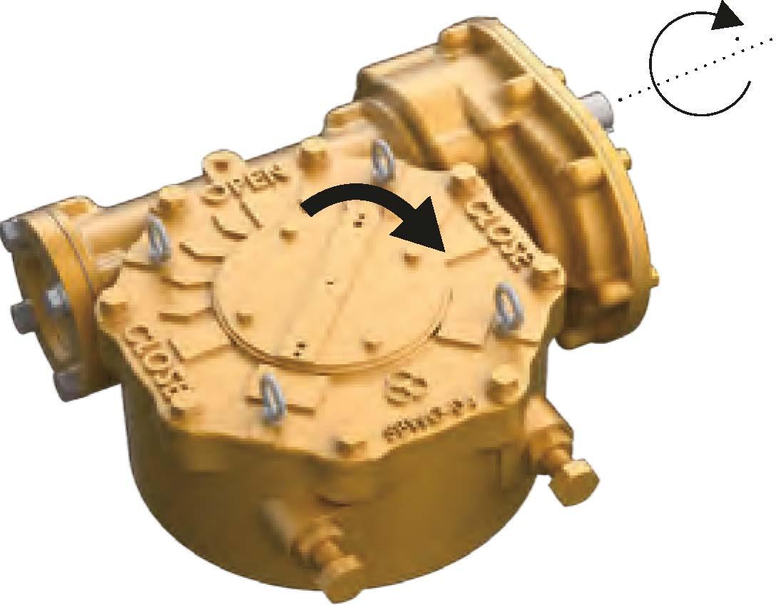
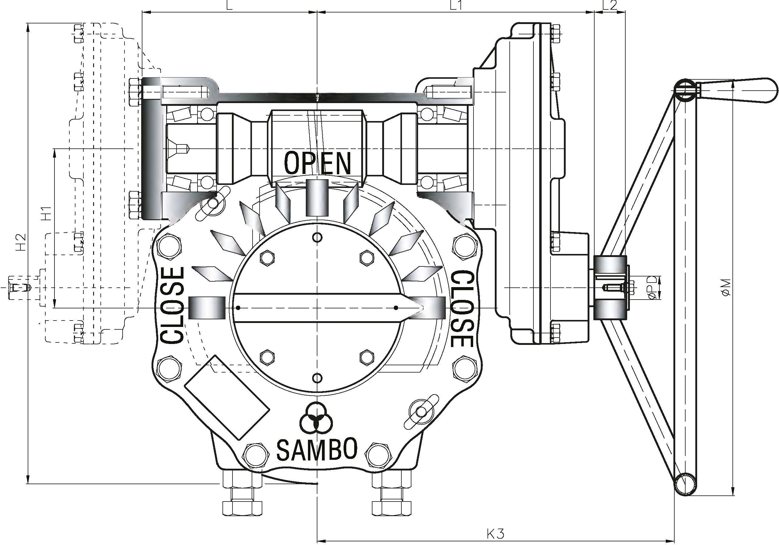
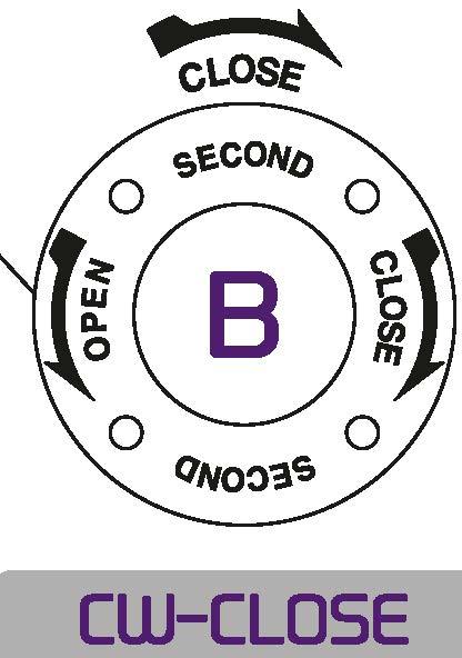
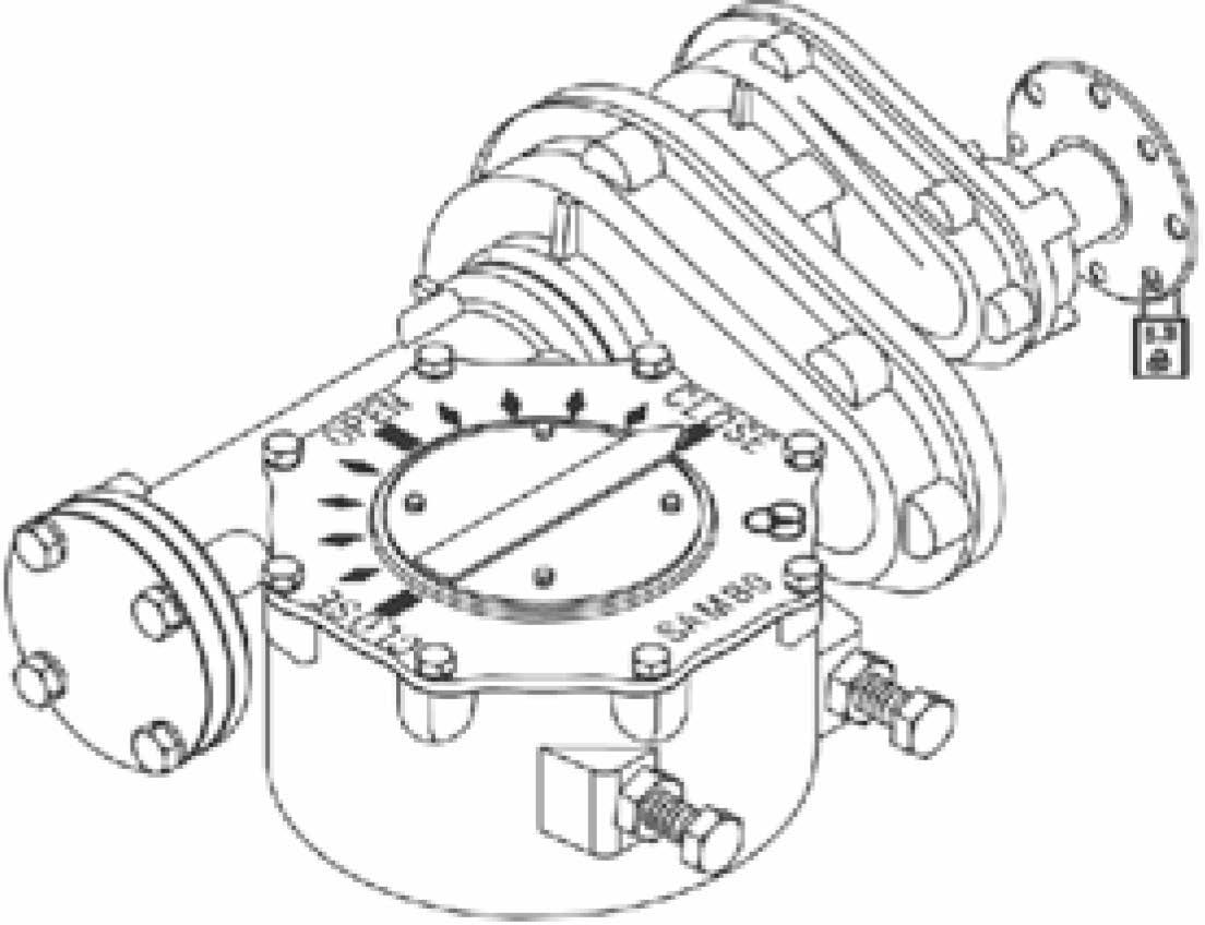
Legends, 'close-Open-Close' are cast directly on the cover.This permits operation in either direction with position indication.
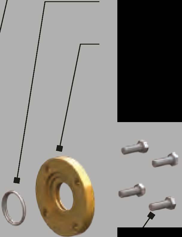
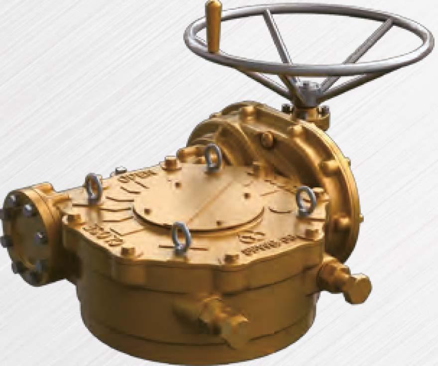
® External Adjustable Stops
The stop bolts allow for position accuracy of +/-5° . Each bolt also includes Buna-N sealing washers or prevent water intrusion

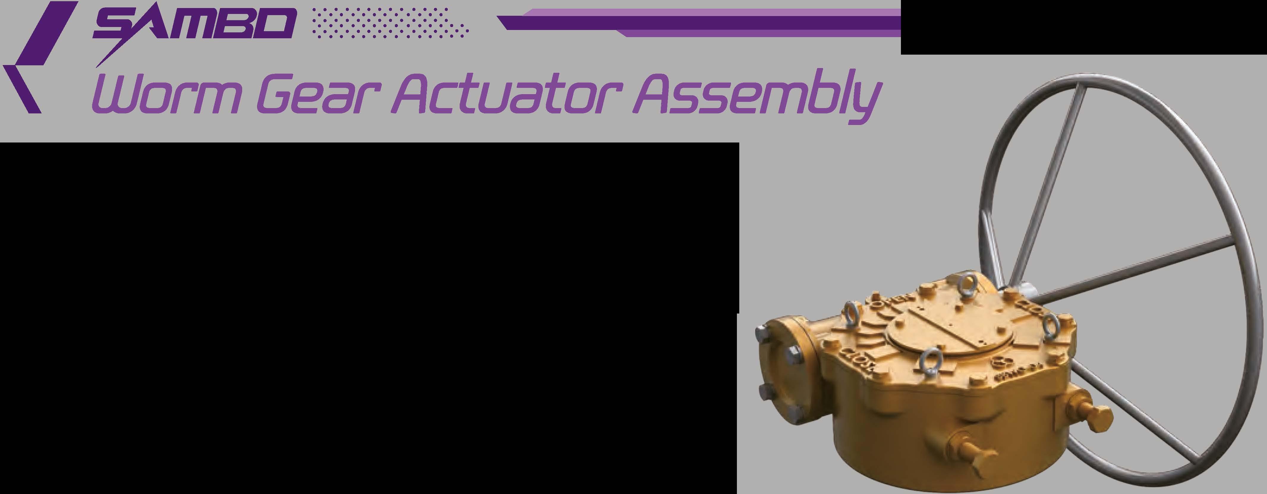
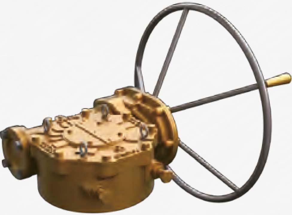
ThisseriesofWorm Gearsrangefrom36DN.m (26Dft-lbf) to970,DODN.m (710,000ft-lbf) >>
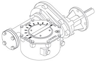
Units are available with single, double and triple reduction spur gear. other options available are : vertical input
(J) Gaskets
Each end of the worm assembly is equipped with special design material(non-asbestos), which are completely water resistant.
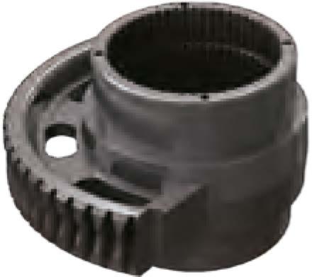
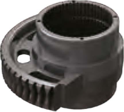
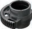
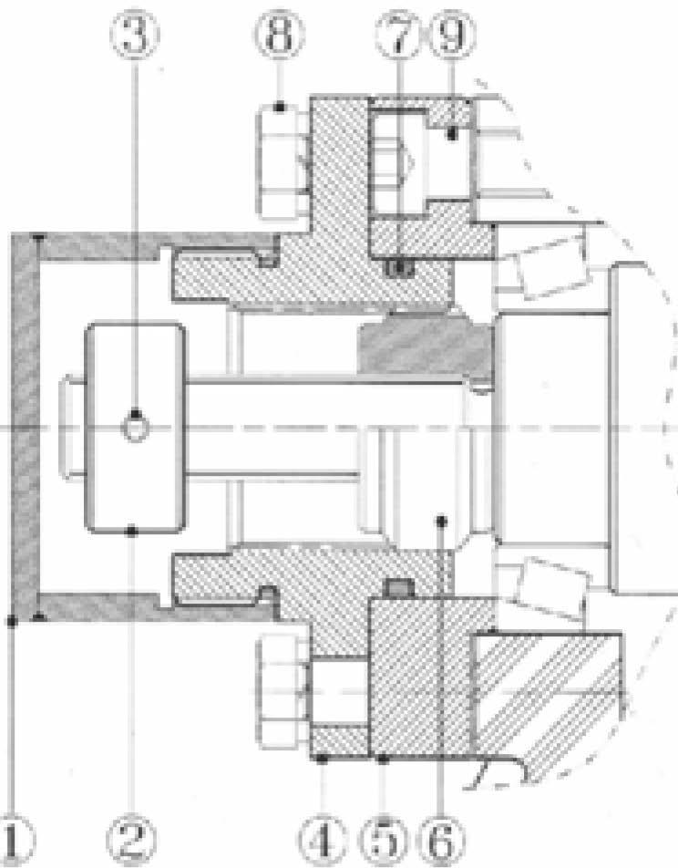
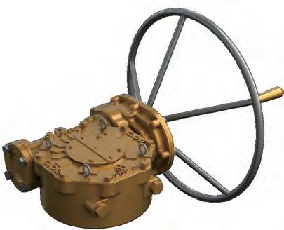
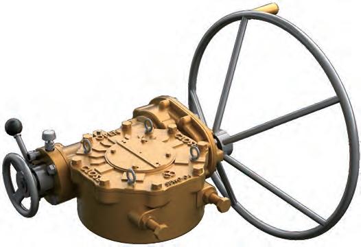
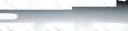
@ Housing
All external castings are Ductile Iron. Class 65-45-12, Tensile Strength of 65,000 psi.
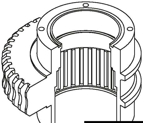
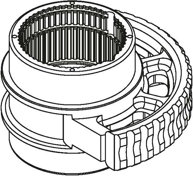
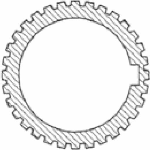
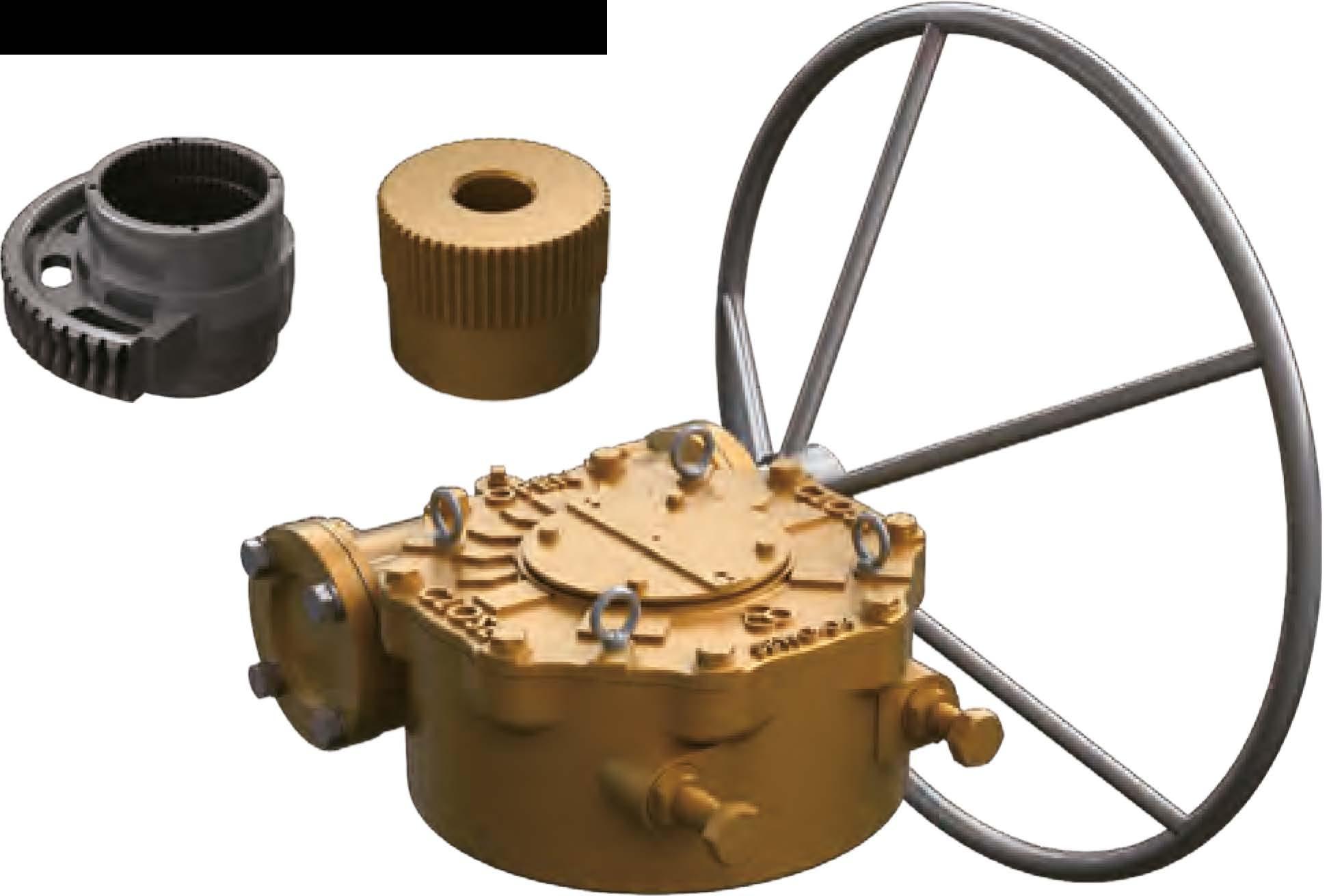
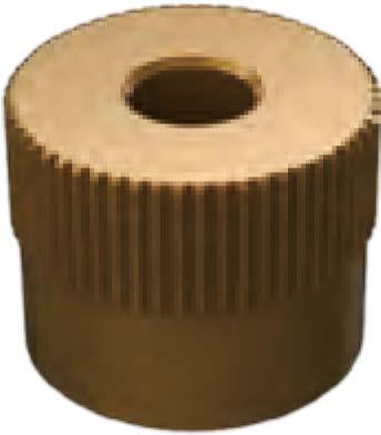
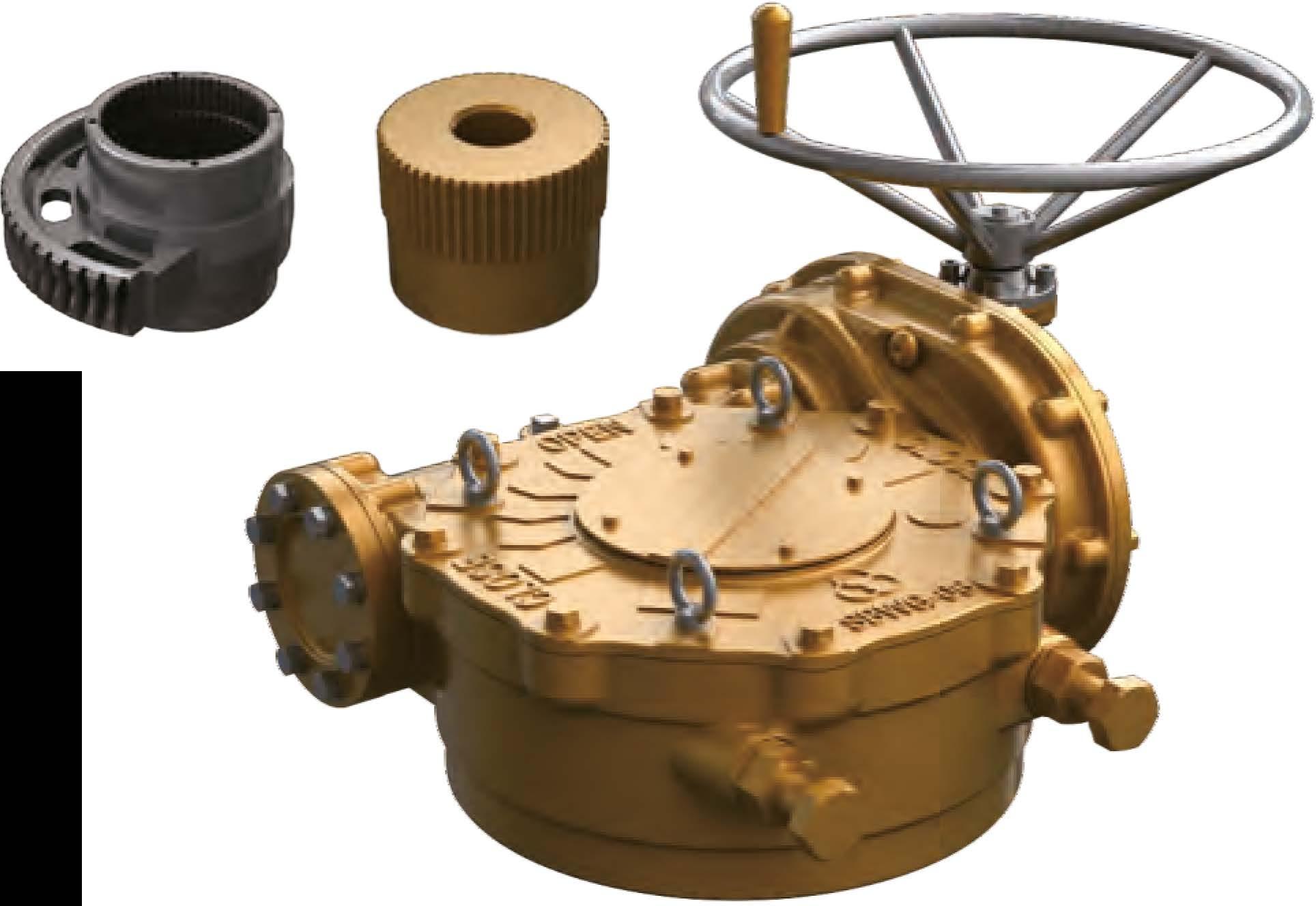
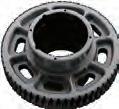
® Splined Bushings
All units furnished with removable splined bushings to permit accurate position between the gear drive and the value shaft.
@) Thrust Washer
The drive sleeve is furnished with hardened steel thrust washers above and below warm gear.
This minuimizes frictional looseness between the gear and the ductile iron castings.
@ Worm Gear
Standard material is Ductile Iron, Grade 80-55-06, Suitable most industrial applications. Option is aluminum bronze having a tensile strength of 85,000 psi Normally required for motorized applications involving modulating service and is also a requirement to meet the AWWA standards.


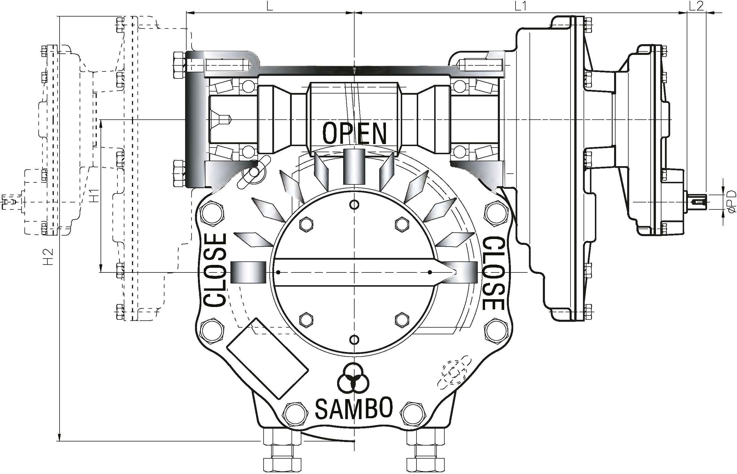
HorizontalInput
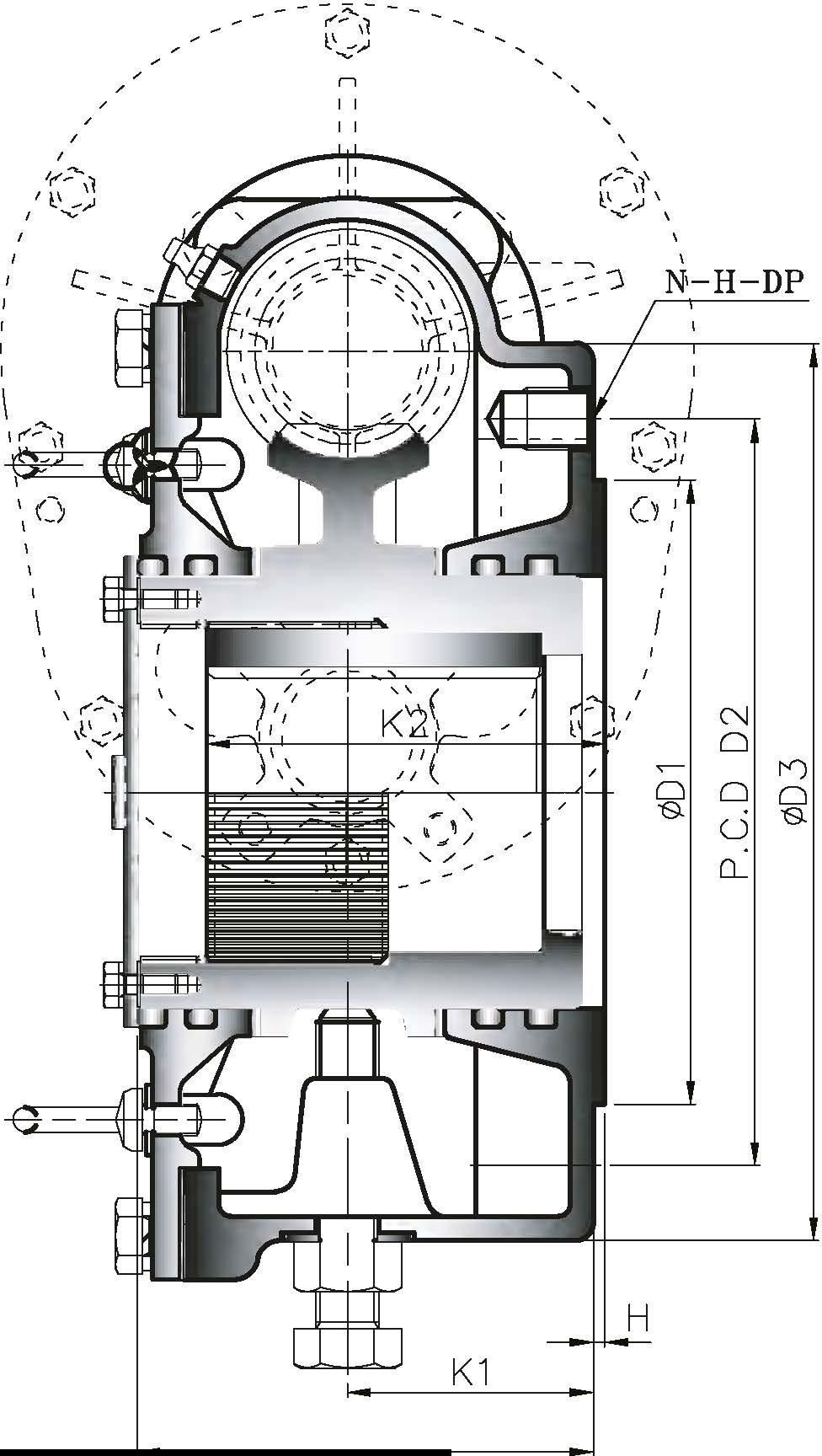
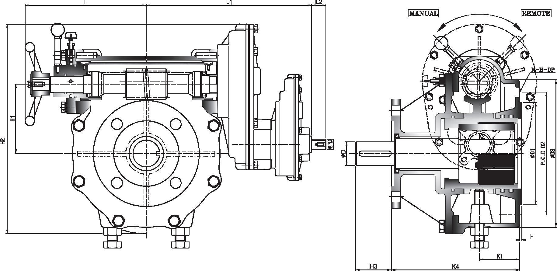
14.HEX.Bolt(P/W)
B.IndicatorPlate�


FCD-450 A536--65-45-12
FCD-450 A536--65-45-12
S45C A576-1045 NOfE.2
FCD-450 A536--65-45-12
FCD-600 A536--80-55--06 B14&-C95800(ALBC3)
FCD-450 A536-65-45-12
FCD-450 A536--65-45-12 SW2 A295-52100SCM435 A322-4135SCM435 A322-4135
S45C A576-1045
S45C A576-1045NOfE.4
VALQUA6601
PackingSeal GreaseFitting EyeBolt HandWheel Key NamePlate Washer HEX.Bolt(S/W) lvanizing lvanizing
1 All castings are Ductile Iron, FCD-450 (ASTIYI Class 55-45-12)
2. In case of option for special request, it can be worked Nickel coating, high tensile stainless.
3. Also, the material can be changed as ALBC3(Aluminium Bronze), steel(A575-1□45), A439 Gr 02[ (Austenitic ductile iron casting) and etc.
4. □-Ring Seal & Lubricant: Standard is Silicon & Buna "N", temperature range -20° [ to+12□° [ (-4° F to+248° Fl. Standard lubricant is Zenith EPSB 2, temperature Range -20· [ to+200° [ (-4° F to+392° Fl
Other option are: High Temperature Viton □-Ring Grade V75, Temperature Range -30° [ to+200° [ (-22° F to+392° Fl
Lubricant - Zenith SYN WS2 Temperature Range -30° [-400° [ (-22° F-752° Fl Low Temperature Silicon □-Ring, Temperature Range -5□° [to+ 15□° [(-75° F to 302° Fl Lubricant - Zenith SBLT5DD, Temperature Range -50° [-120° [ (-75° F-248
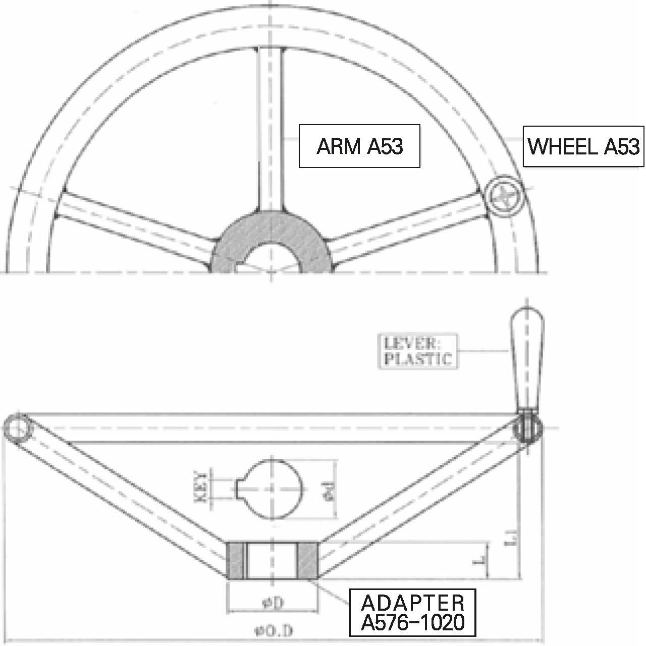
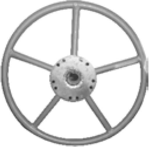
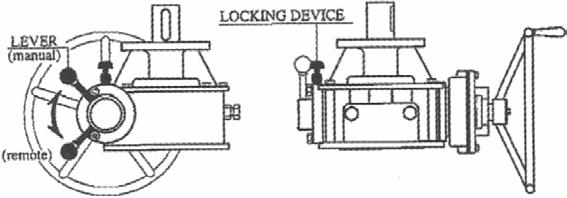
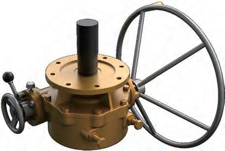
5. SAIYIBD offers a wide variety of Handwheels, Chainwheels, Input Shaft, Locking Devices and etc
5. SAIYIBD offers a wide variety of stem cover, stainless steel, Polycarbonate.
Paint: Unless specified, units are supplied with vp134 Red epoxy primer. SAIYIBD can provide finish coating upon request

DuctileIron
CarbonSteelS45C A57&-1045
DuctileIron FCD-450 A536--65--45-12
DuctileIron FCD--600A536--80--55-06B148-al5800(ALBC3)
DuctileIron FCD-450 A536-65-45-12
DuctileIron FCD-450 A536-65-45-12
Steel+EP
Steel
Steel
SpecialSteel SW2 A295-52100
AlloySteel SCM435 A.322-4135
AlloySteel SCM435 A.322-4135
StainlessSteel
CarbonSteelS45C A57&-1045
CarbonSteelS45C A57&-1045
PackingSeal
GreaseFitting 25 EyeBolt
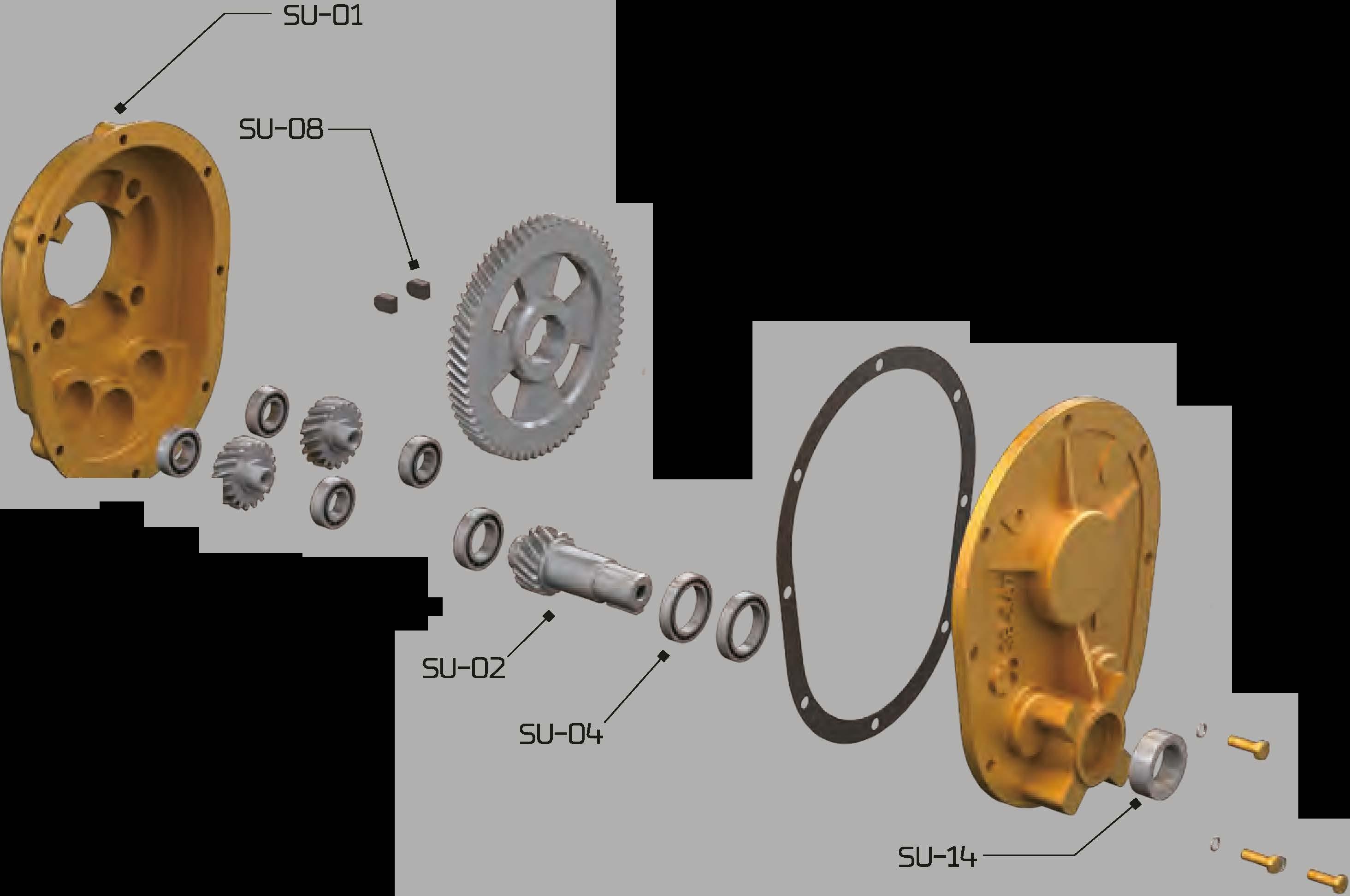
SlHJ1 SupportHousing
SlHJ2 HelicalPinion
SlHJ3 RadialBallB/R
SlH)4 RadialBallB/R
SlHJ5 IdleGear
Sl l6 RadialBallB/R
SlHJ7 HelicalGear
SlJ--08 Key{1R)
Sl J9 SnapRing
SU-10 RadialBallB/R
SU-11 SupportCover
SU-12 &-CoverGasket
SU-13 HEX.Bolt(S/W)
SU-14 Oil-Seal
OP--01 HandWheel
OP--02 Key{1R)
OP--03 NamePlate
OP-04 Washer
OP--05 HEX.Bolt(S/W)
Silicon
Steel+Galvanizing
Steel+Galvanizing
DuctileIron FCD-450
CarbonSteelS45C
SpecialSteelSW2
SpecialSteelSW2
CarbonSteelS45C
SpeciialSteelSW2
CarbonSteelS45C
CarbonSteelS45C
CarbonSteelS45C
SpecialSteelSW2
DuctileIron FCD-450
Nonasbestos
AlloySteel SCM435
BunaN NBR
SteelPipe SGP
CarbonSteelS45C
StainlessSteel
StainlessSteel
StainlessSteel
A536--65--45--12
A57&-1045
A295-52100
A295-52100
A57&-1045
A295-52100
A57&-1045
A57&-1045
A57&-1045
A295-52100
A536--65--45--12
A.322-4135
A53
A57&-1045
DuctileIron FCD-450 A536----65----45-12
NO DESCRIPTION
23 PackingSeal
NAME M,lij"ERIAL JIS ASTM
Silicon
REMARK
DuctileIron FCD-450 A536----65----45-12 CarbonSteel S45C A57&-1045 Ductile
24 GreaseFitting
25 EyeBolt
A536----65----45-12
DuctileIron FCD-600A536-80-55-06B1<18-C95800(ALBC)
DuctileIron FCD-450A536----65----45-12
DuctileIron FCD-450A536----65----45-12
S45C S45C Non-Asbestos Non-Asbestos A295-52100 A322-4135 A322-4135 A57&-1045 A57&-1045
NOfE.3
VAL.QUA6601
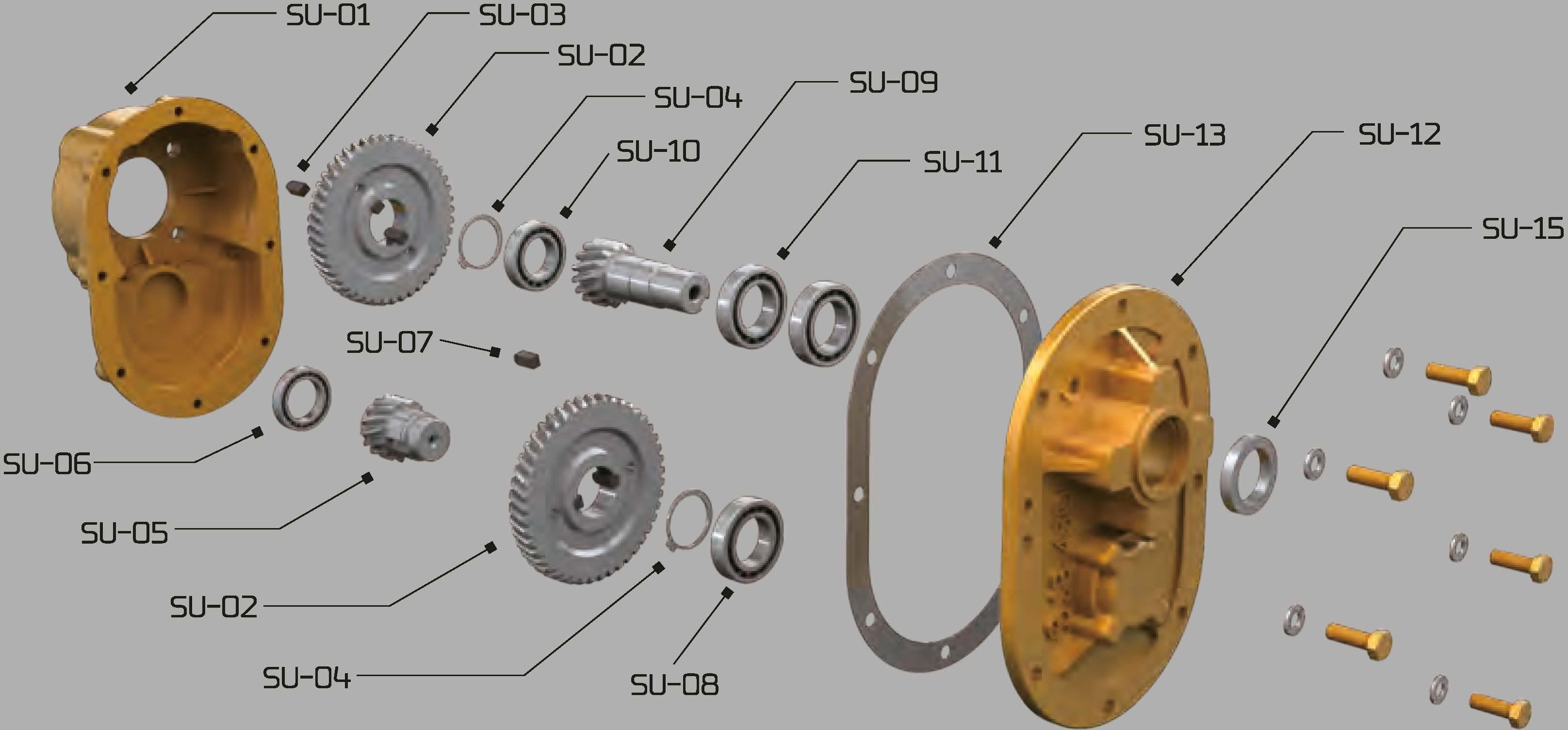
SlHl1 SupportHousing
SlHl2 HelicalGear
SlHl3 Key{1R)
SlH)4 SnapRing
SlHl5 IdleGear
Sl l6 RadialBallB/R
SlHl7 Key(1R)
SlJ--08 RadialBallB/R
SlH)9 HelicalPinion
SU-10 RadialBallB/R
SU-11 RadialBallB/R
SU-12 SupportCover
SU--13 &-CoverGasket
SU--14 HEX.Bolt(S/W)
SU--15 Oil-Seal
OP--01 HandWheel
OP--02 Key{1R)
OP--03 NamePlate
OP-04 Washer
OP--05 HEX.Bolt(S/W)
Steel+Galvanizing
Steel+Galvanizing
DuctileIron FCD-450
CarbonSteel S45C
CarbonSteel S45C
CarbonSteel S45C
CarbonSteel S45C
SpecialSteel SUJ2
CarbonSteel S45C
SpecialSteel SUJ2
CarbonSteel S45C
SpecialSteel SUJ2
SpecialSteel SUJ2
DuctileIron Nonasbestos
Stainless FCD-450 SCM435
BunaN SteelPipe
CarbonSteel
StainlessSteel
StainlessSteel
StainlessSteel NBR SGP S45C
A536--65--45--12
A57&-1045
A57&-1045
A57&-1045
A57&-1045
A295-52100
A57&-1045
A295-52100
A57&-1045
A295-52100
A295-52100
A536--65--45--12
A322-4135
A53
A57&-1045

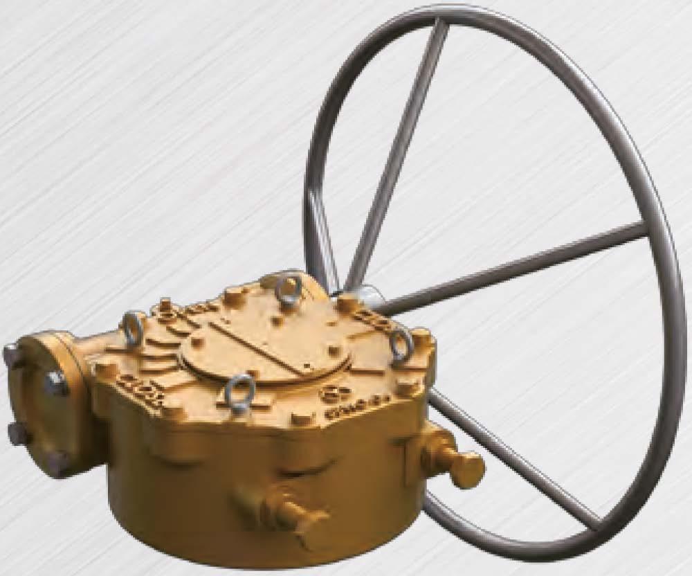
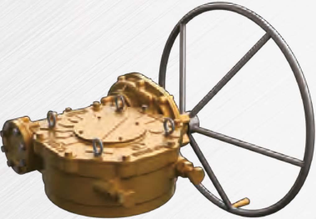
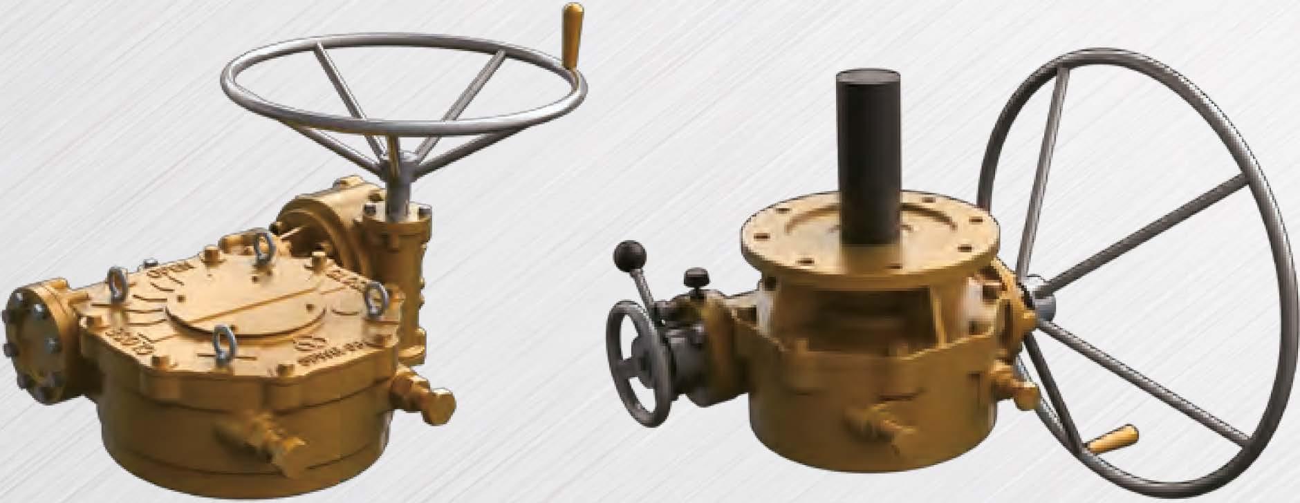
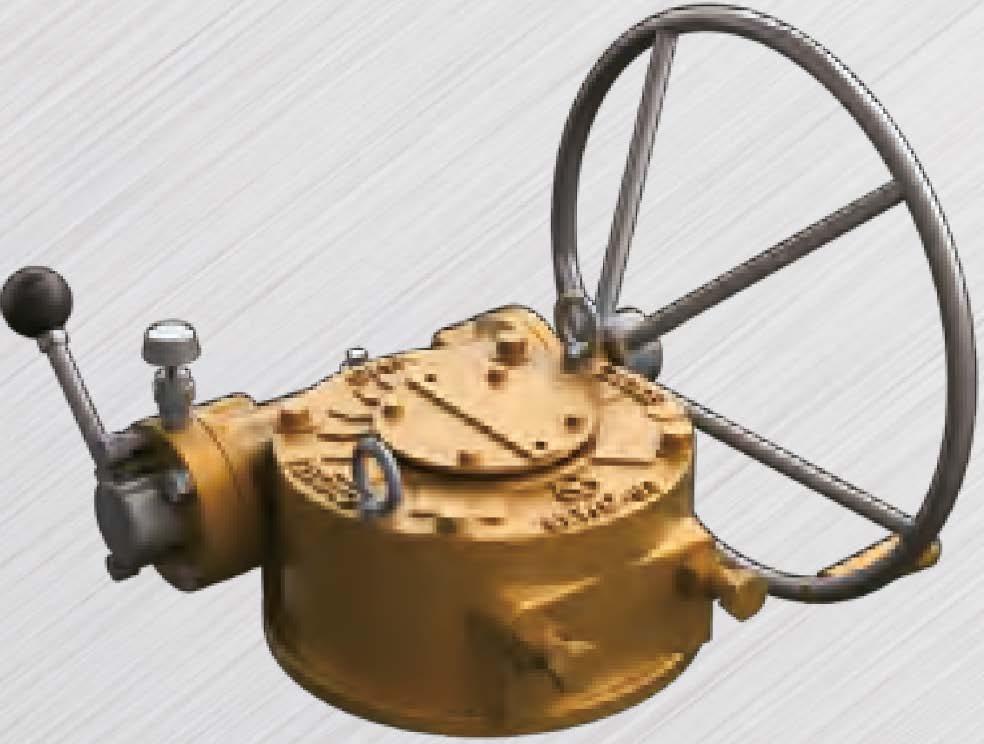
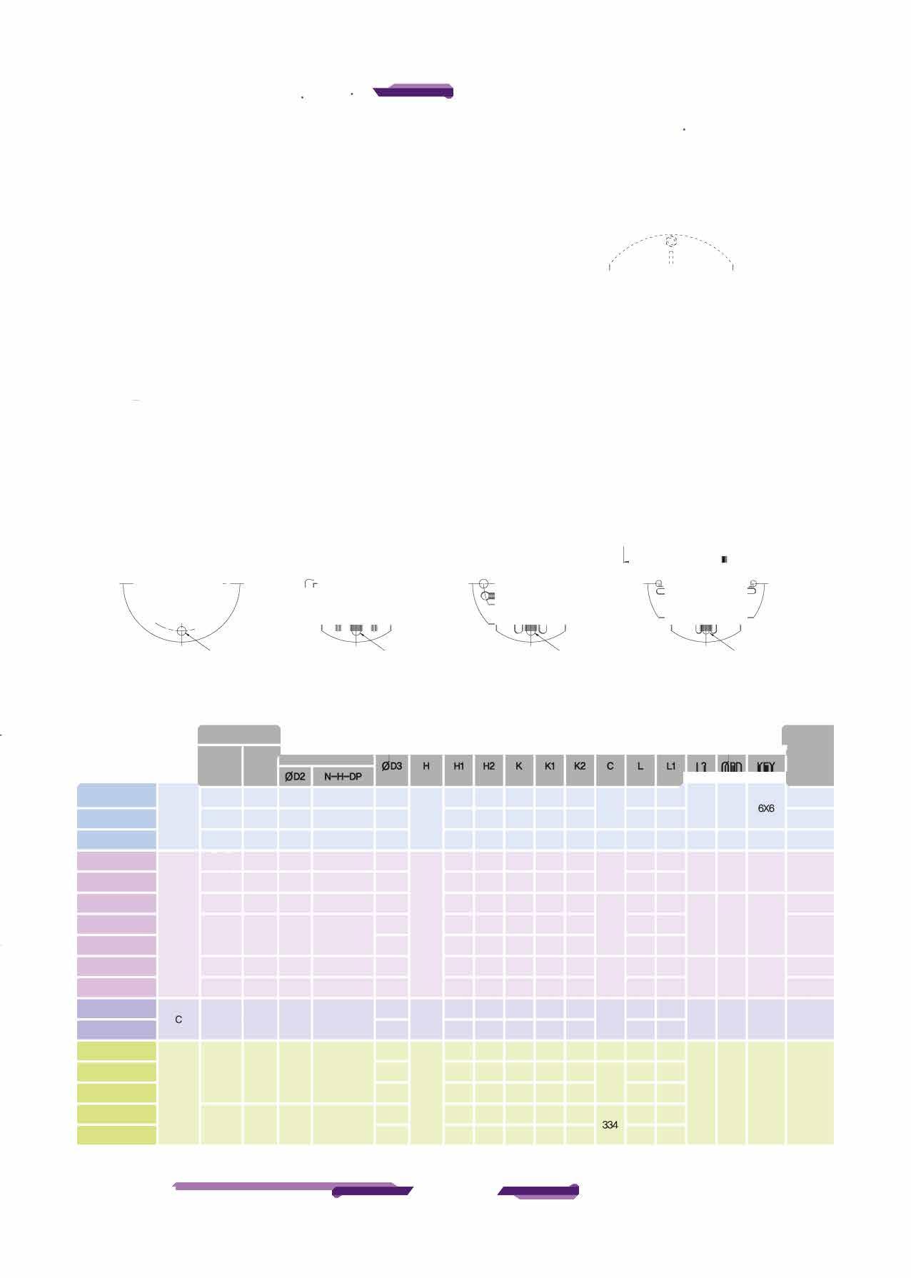
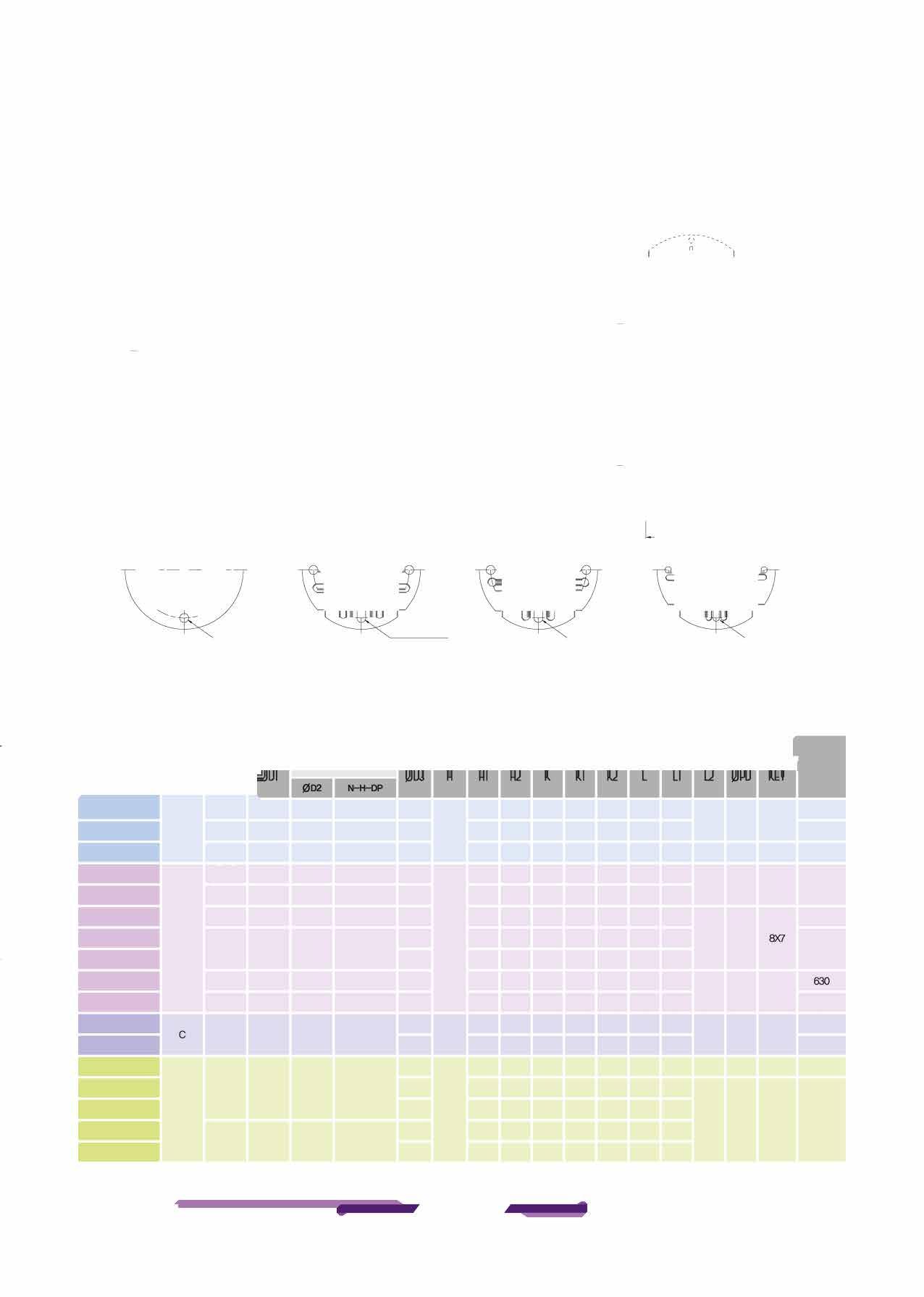
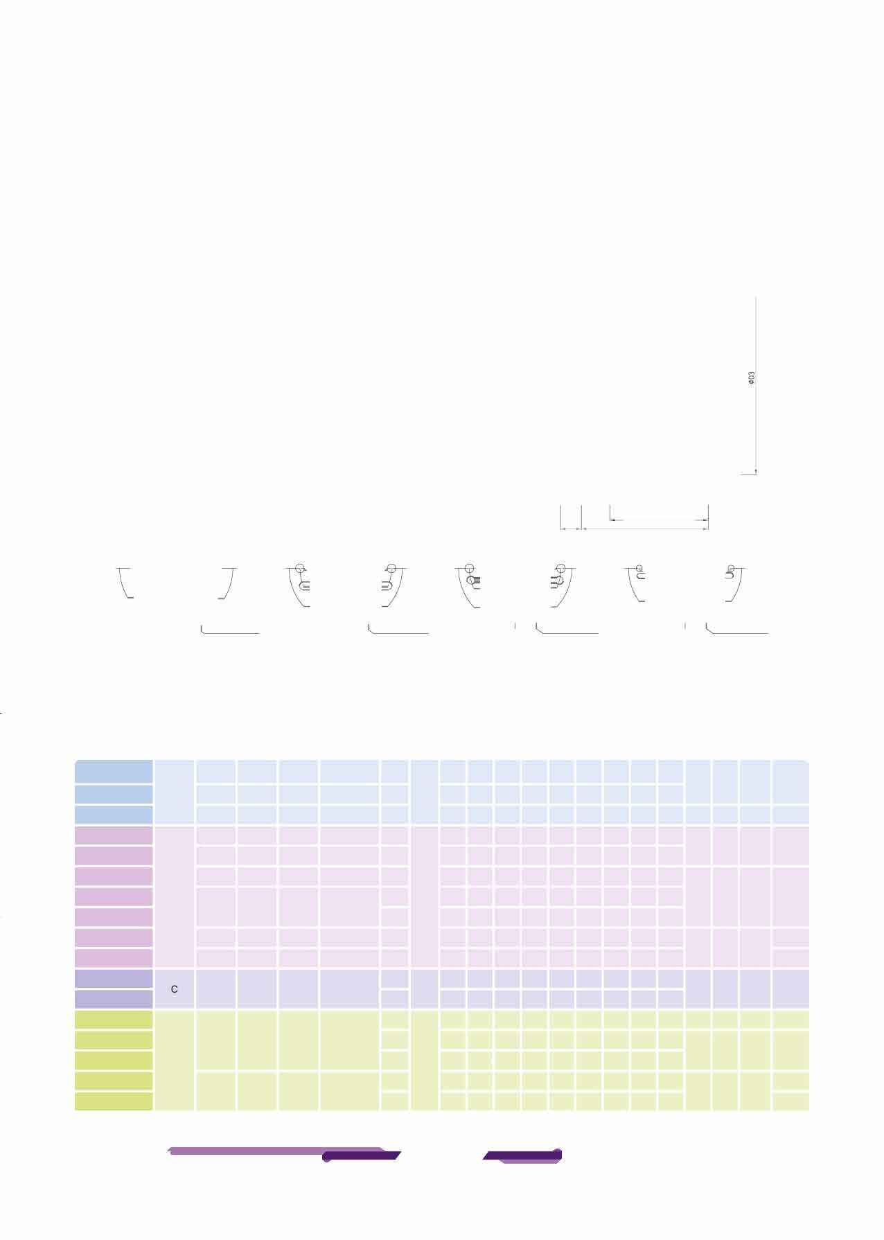
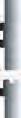
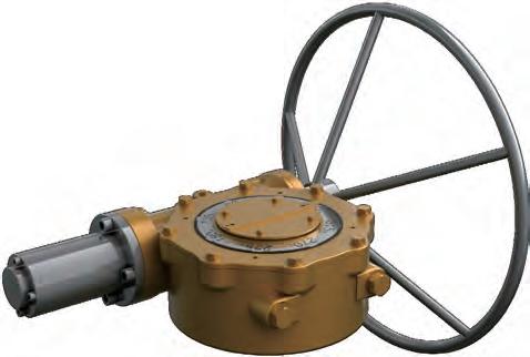
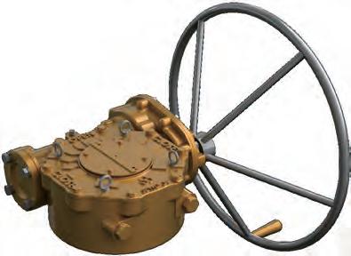
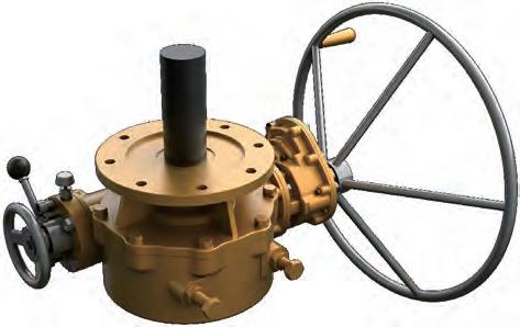
Hand WheelType & Chain Wheel Type
Bush Insert & Setscrew /Twin Shaft Gear Actuator Type
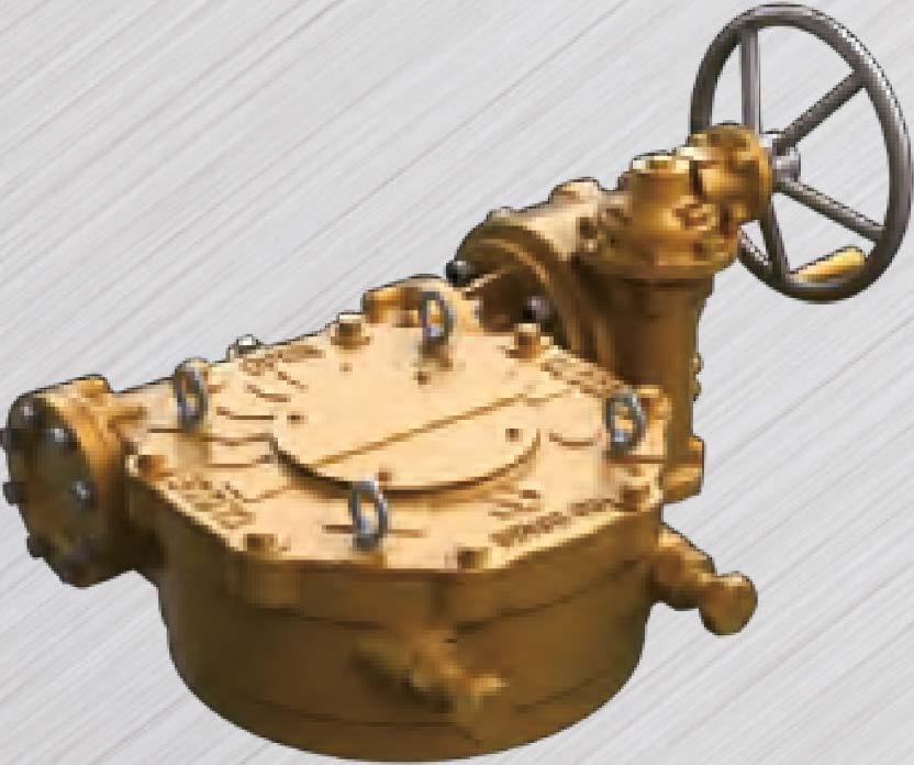
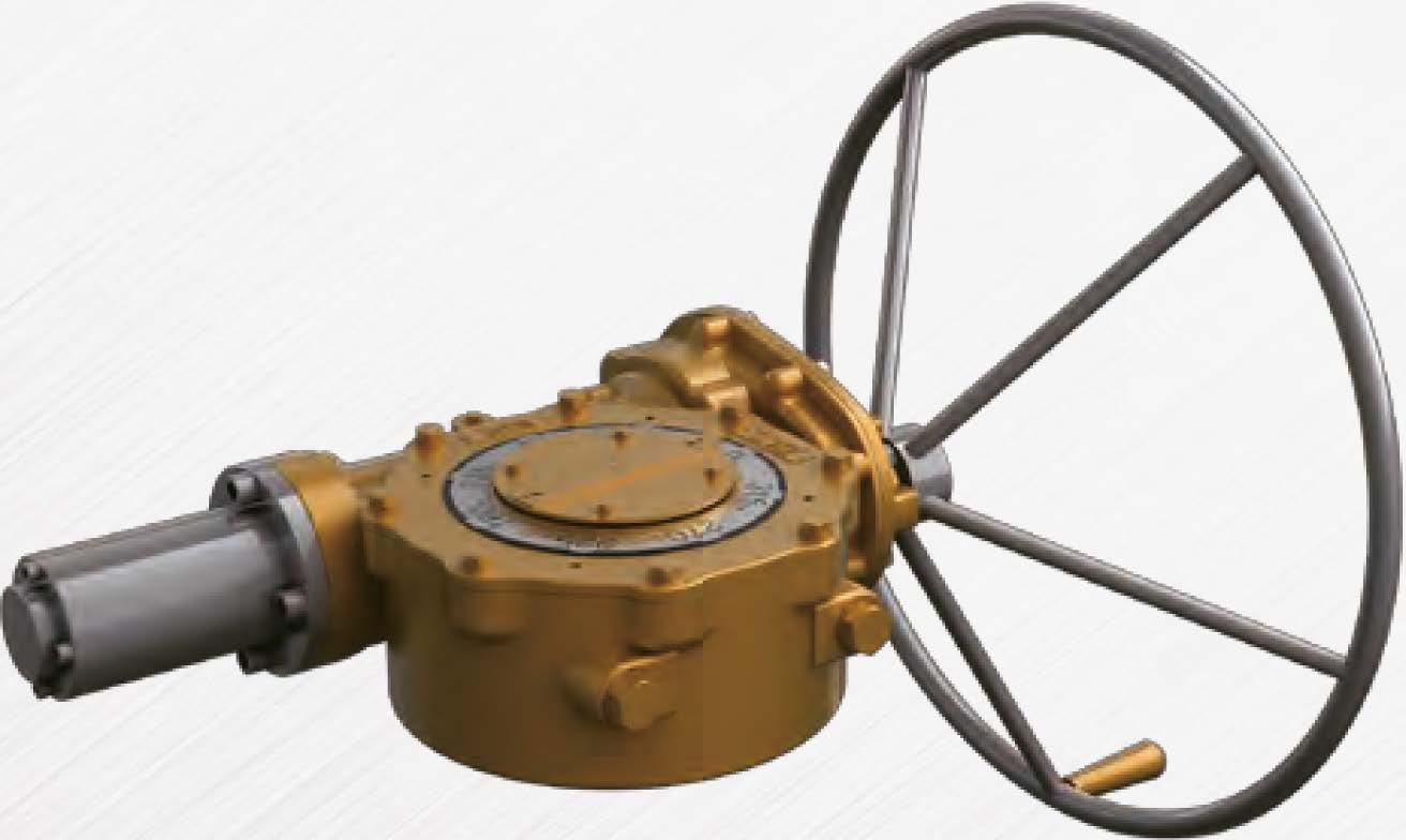
StandardTypeA
Horizontal Input
StandardTypeA
Horizontal Input with Single Reduction Gear Attachment StandardTypeA-TwinShaft
Horizontal Input with Single Reduction Gear Attachment
StandardType A
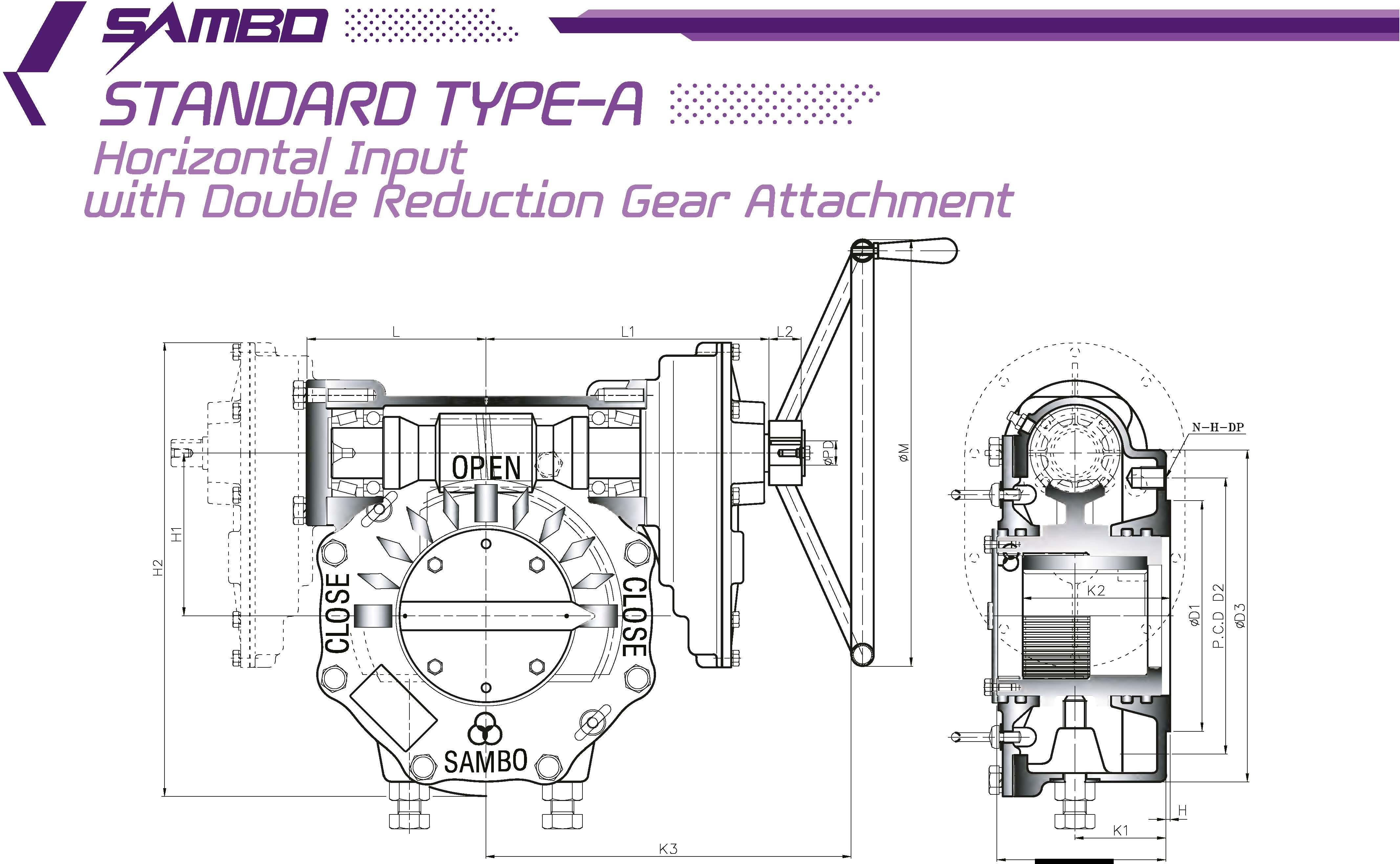
Horizontal Input with Double Reduction Gear Attachment StandardTypeA-TwinShaft
Horizontal Input with Double Reduction Gear Attachment
StandardTypeA
Horizontal Input with Triple Reduction Gear Attachment


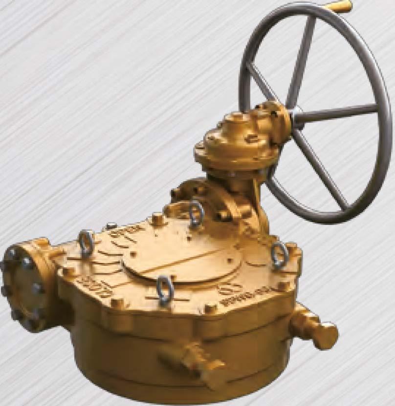
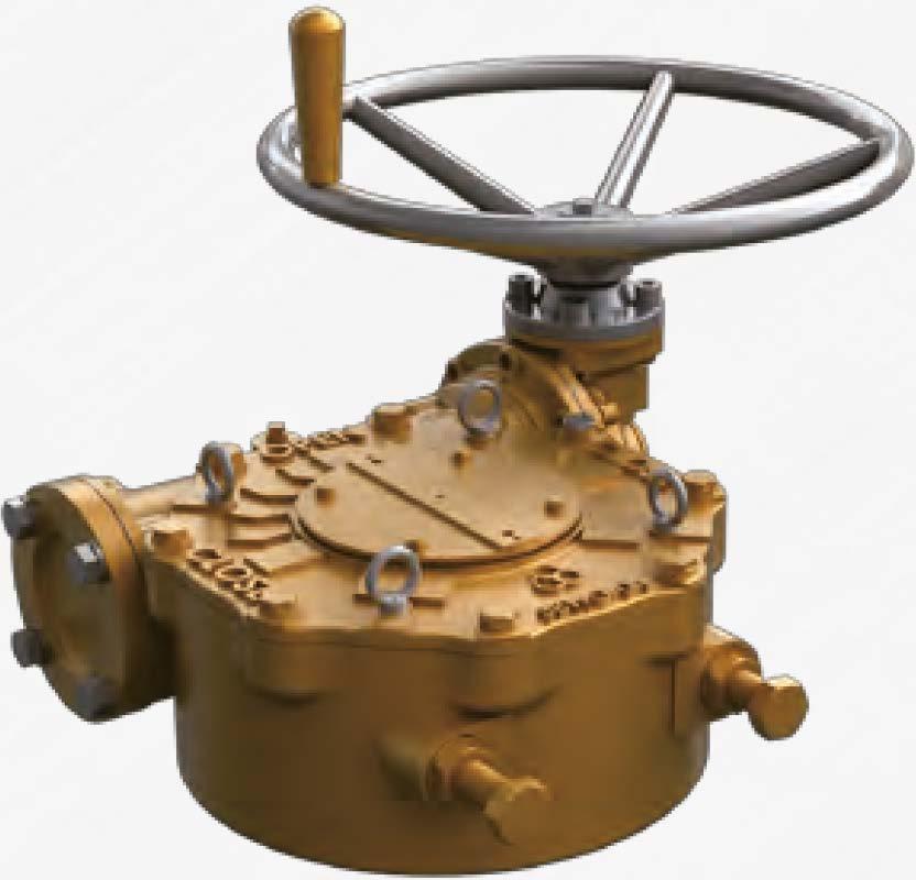
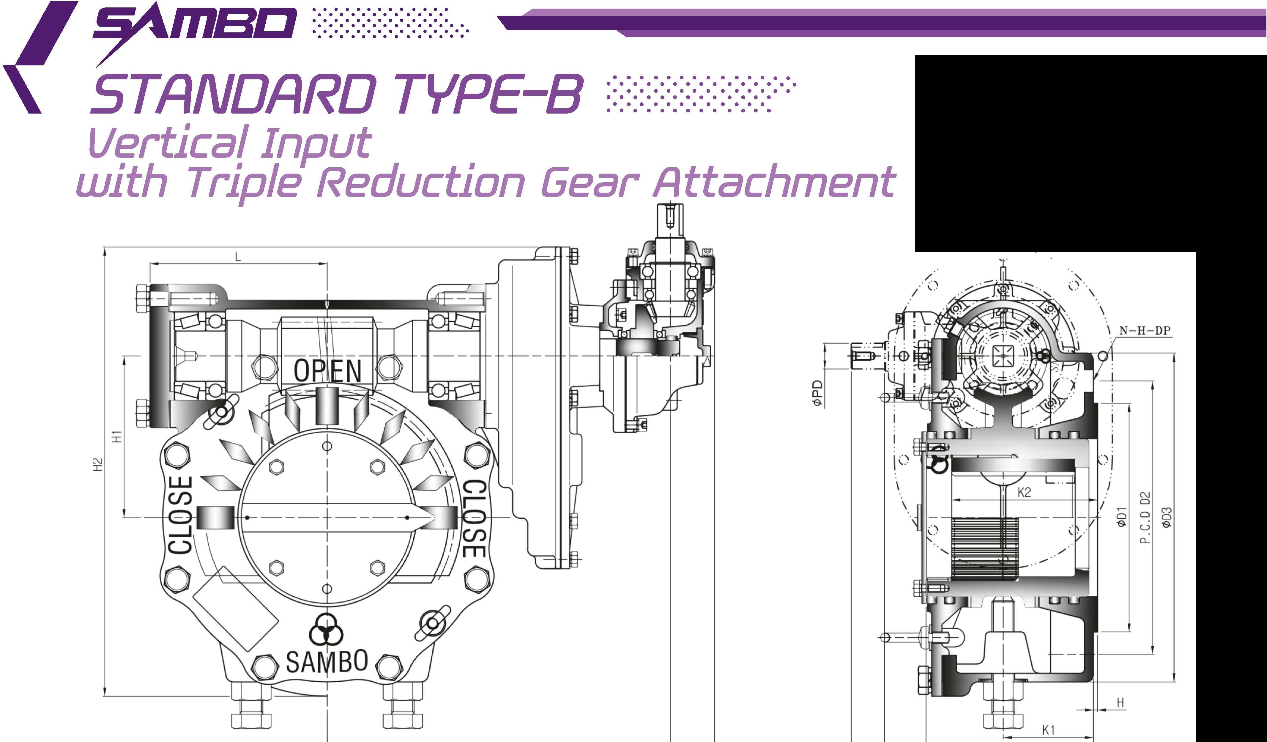
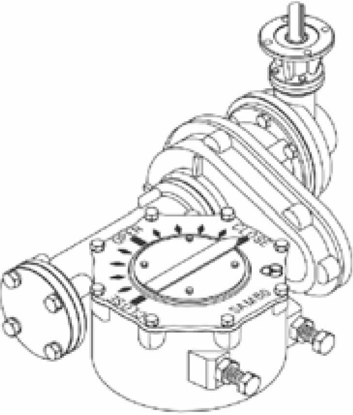
StandardType B
Vertical Input with Double Reduction Gear Attachment
StandardType B
Vertical Input with Triple Reduction Gear Attachment
StandardType B
Vertical Input with Single Reduction Gear Attachment
StandardType C
Horizontal Input with Double Reduction Gear Attachment
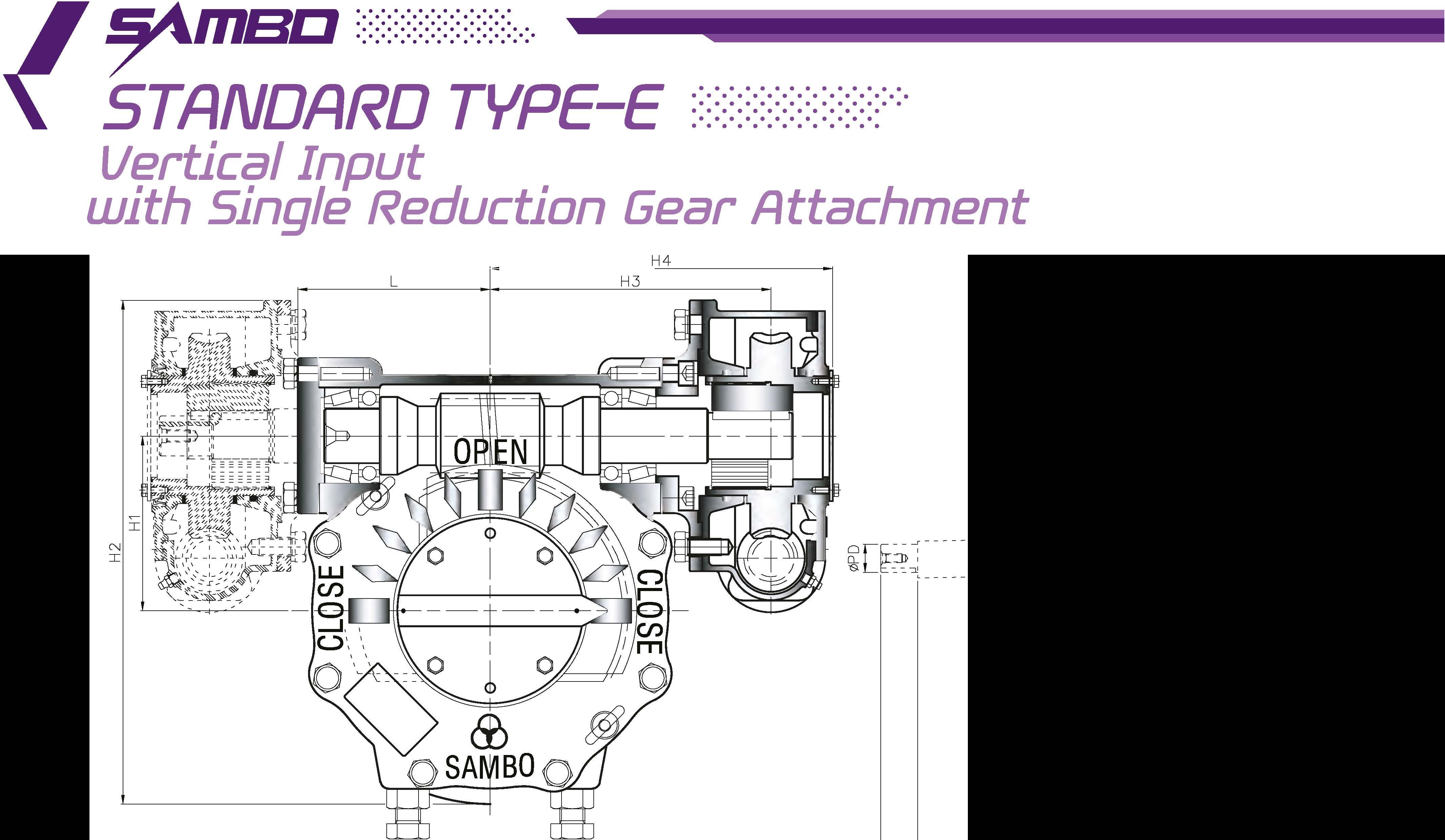
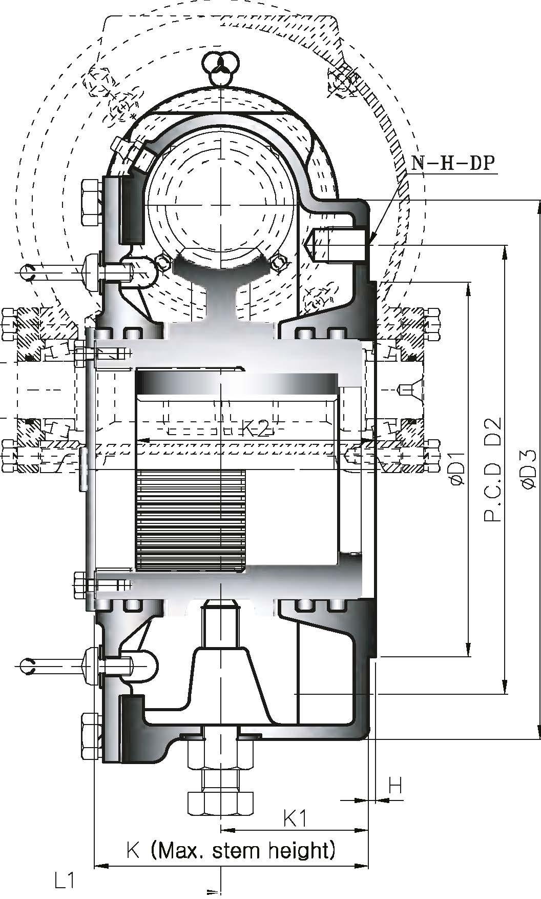
StandardType E
Vertical Input with Single Reduction Gear Attachment
StandardType E
Vertical Input with Double Reduction Gear Attachment
PartTum135°
Horizontal Input
PartTum135•
Horizontal Input with Single Reduction Gear Attachment
PartTum135•
Horizontal Input with Double Reduction Gear Attachment
PartTum l8D0
Horizontal Input
PartTum l8D0 _,,Horizontal Inp�t with Single Reduction Gear Attachment /PartTum180
Horizontal Input with Double Reduction Gear Attachment
PartTum-45°,90
Horizontal Input
0eclutch Gear-45
,90
,135
,180
l'klrizontal Input with Single Reduction Gear Attachment
Declutch Gear-45°,90
Horizontal Input with Double Reduction Gear Attachment
MultiTurn360•
Horizontal Input
MultiTurn360•
Horizontal Input with Single Reduction Gear Attachment
MultiTurn360•
Horizontal Input with Double Reduction Gear Attachment
Declutch Gear
Horizontal Input
Declutch Gear
Horizontal Input with Single Reduction Gear Attachment
Declutch Gear /
Horizontal Input with Triple Reduction Gear Attachment
Declutch Gear- Pneumatic Actuators
HorizontalInput
Declutch Gear- Pneumatic Actuators
Horizontal Input with Single Reduction Gear Attachment
Declutch Gear- Pneumatic Actuators


If
As
This Handwheel is the type using air impact wrench and if can be made properly according to customer' s request
Size and component specitication in this catalogue are subject to change without prior notice for
• IYlark has been changed and updated

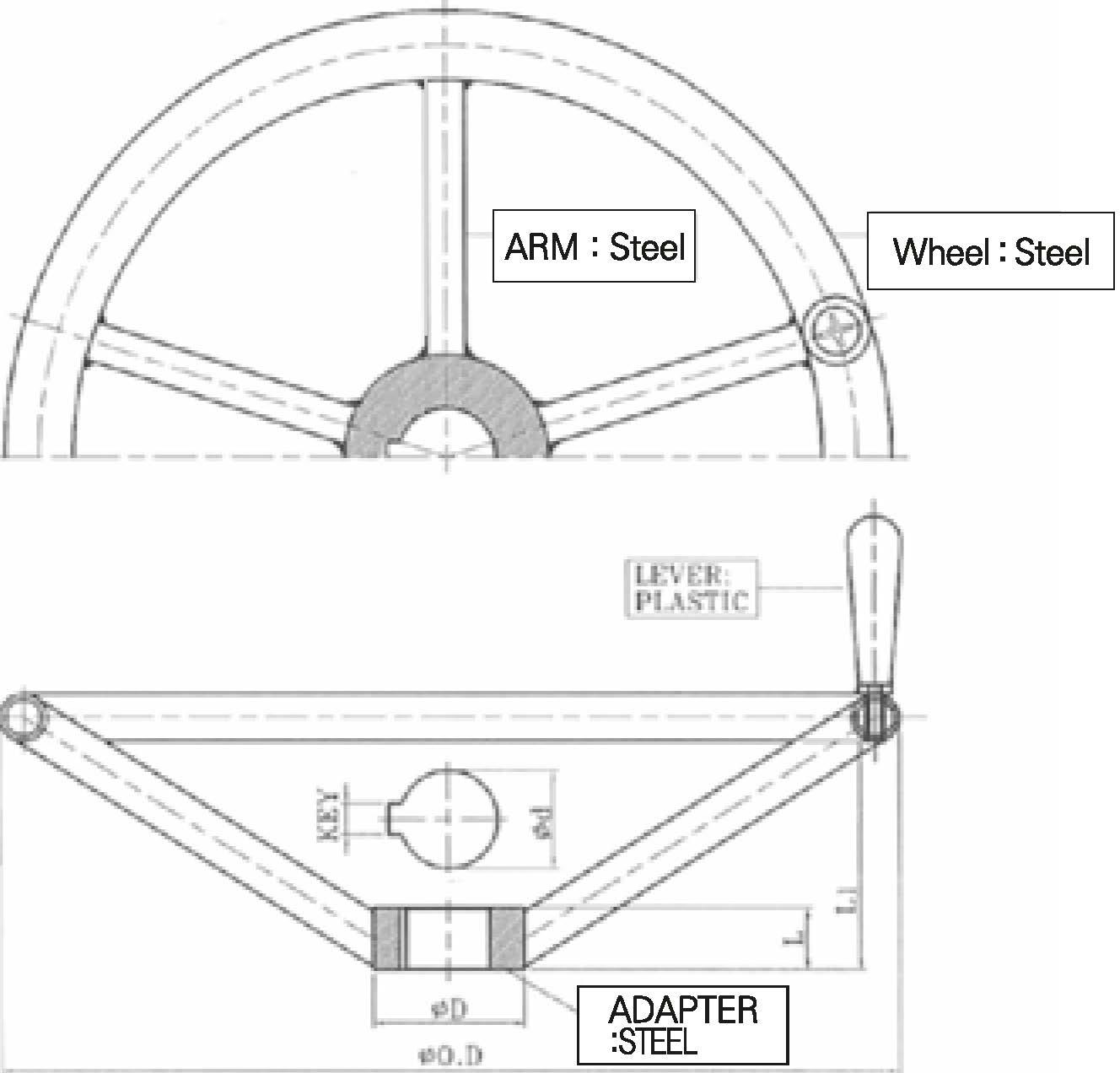
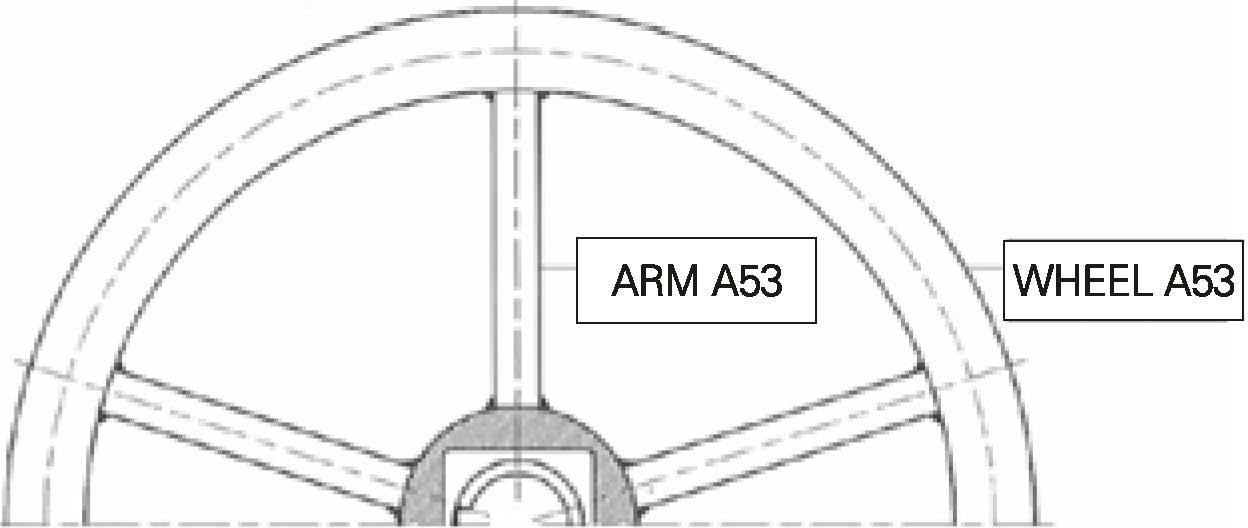
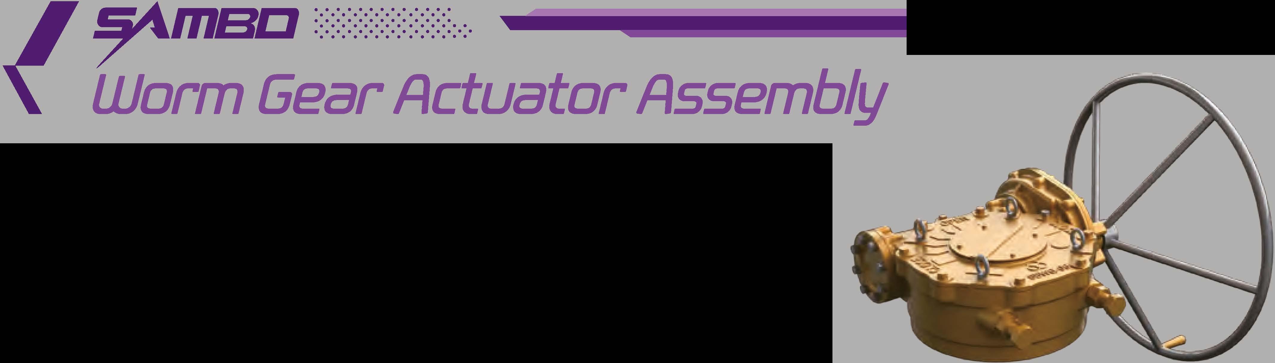
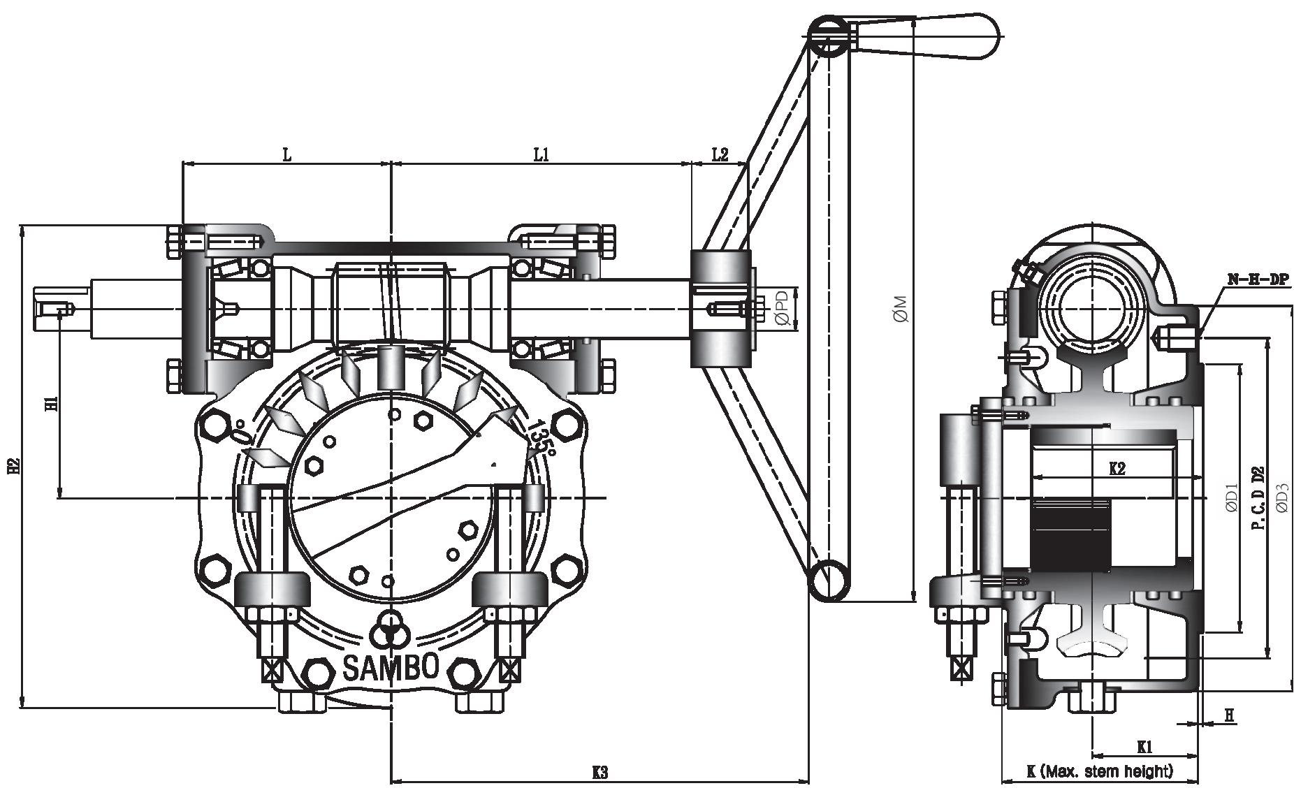
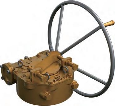
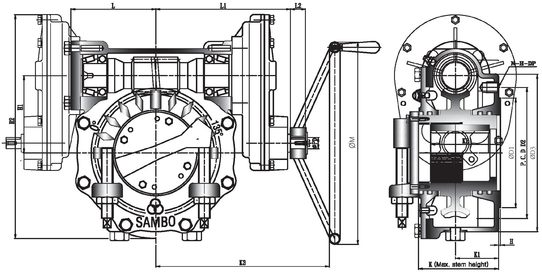
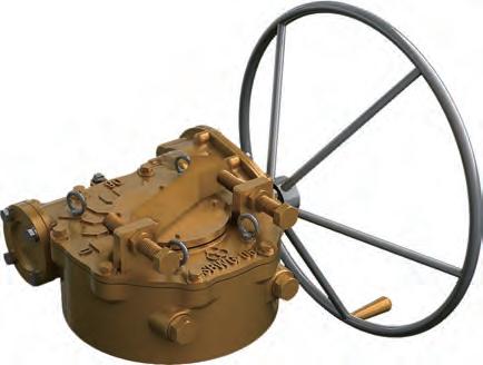
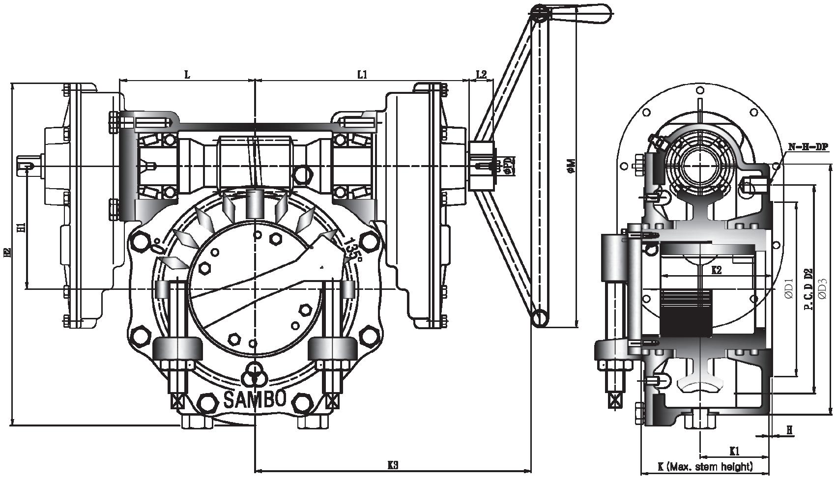
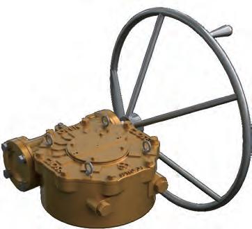
WORM Standard >>>
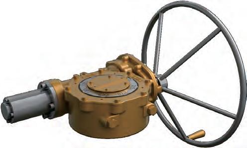
Chainwheel has 2 types


• First, hammer type which is joined with handwheel.
• Second, gear type which is adhered to gear directly.
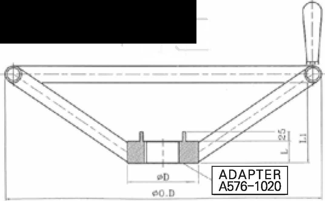
• material : sprocket rim (Fc□-450), guide arm (Fc□-450), chain (steel+zn)
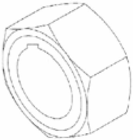
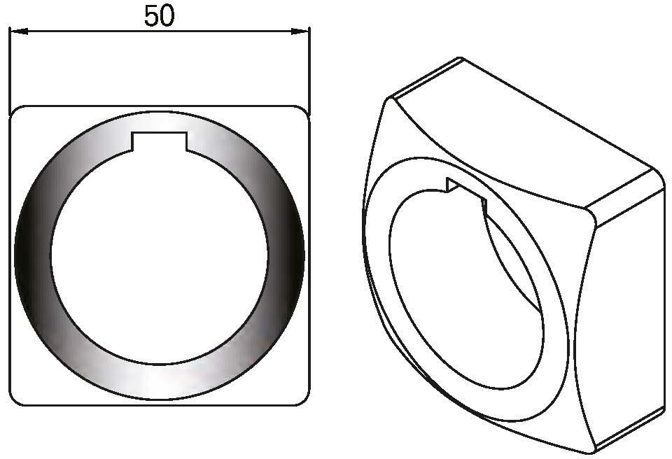
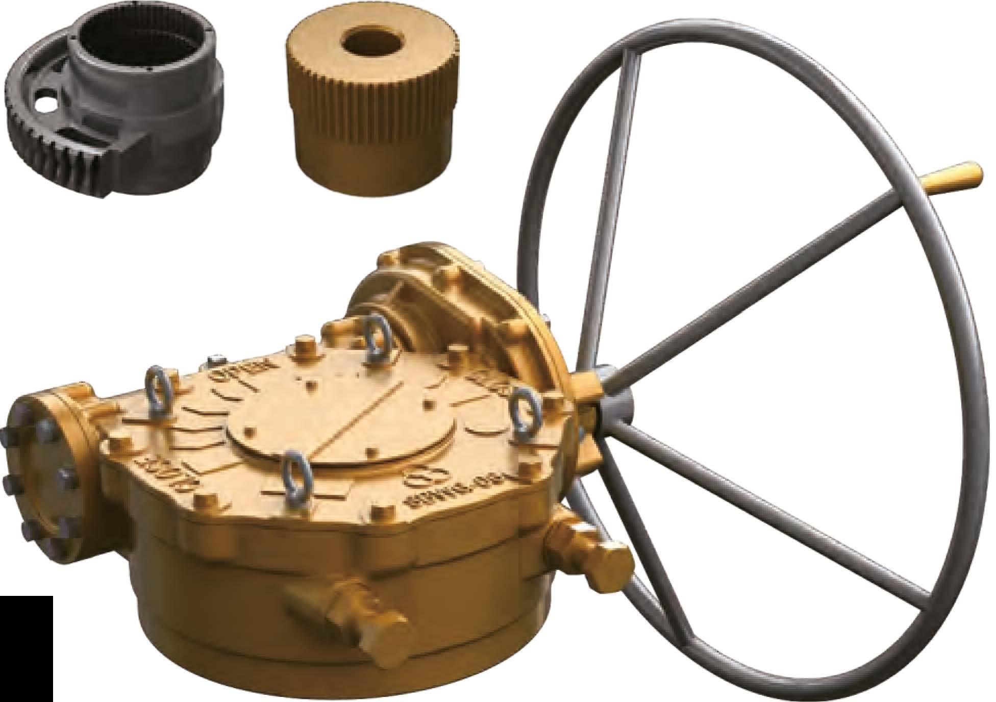
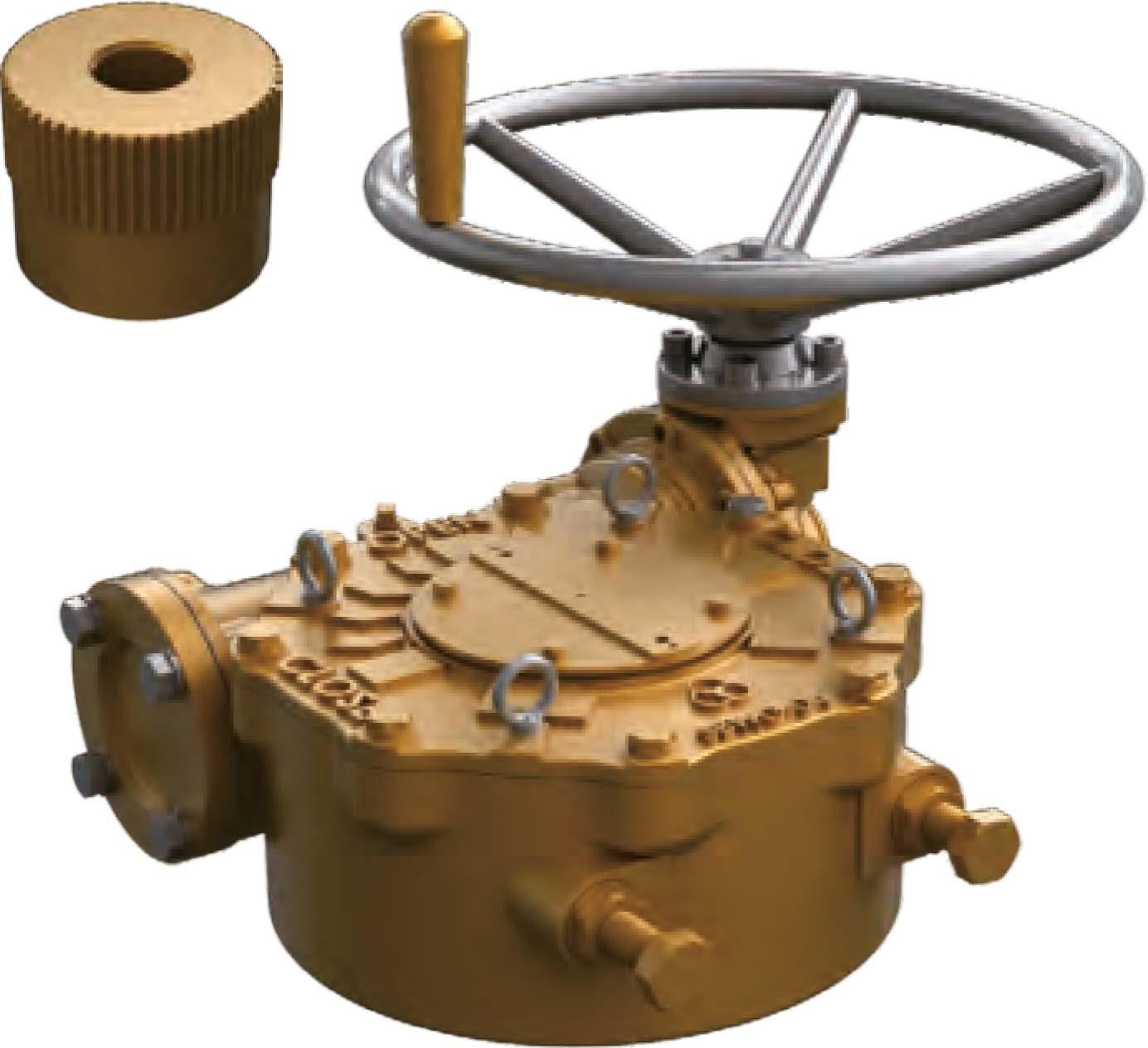
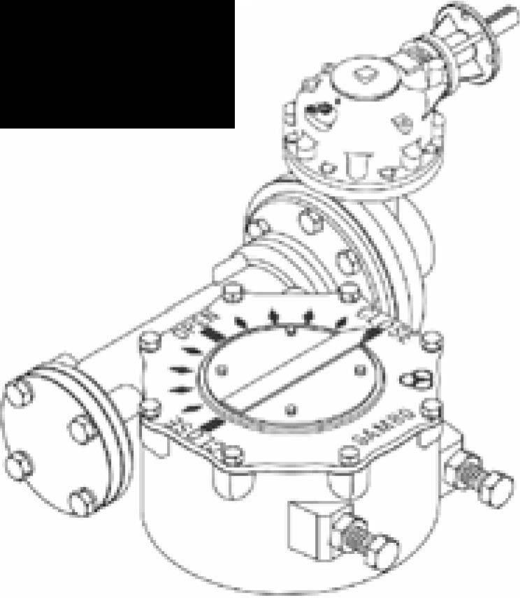
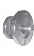
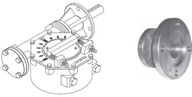
Square Adapter >>>
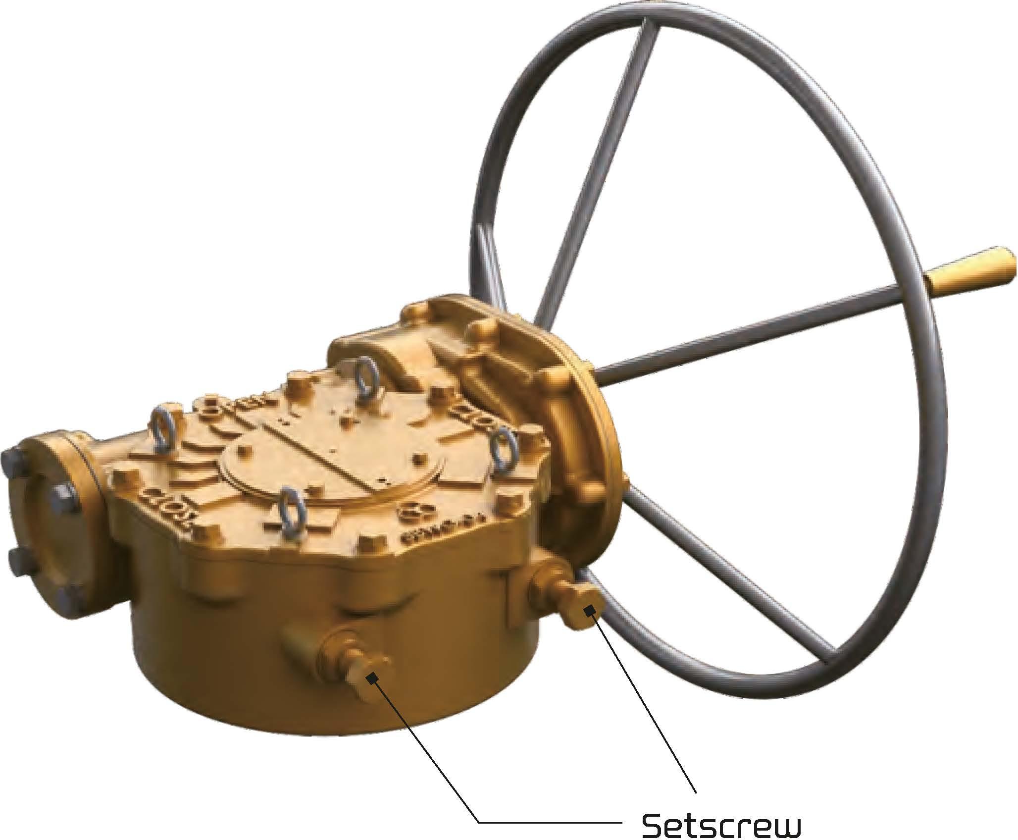
1. Secure setting for the valve and actuator correctly. 2. After finish setting. finally use to adjust the setscrews of worm gearbox.
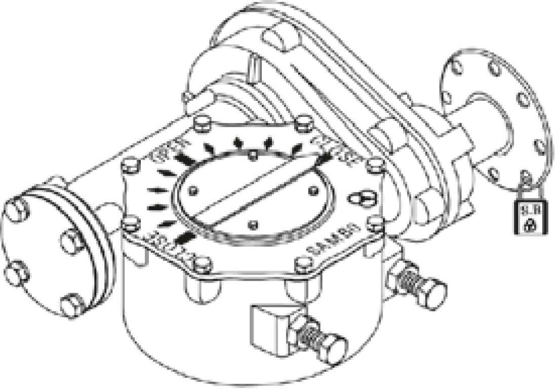
WARNING
• SAIYIBD worm gearboxes are not set at exactly 90 degree.
• After complete valve and actuator, accurately adjust and use setscrews.
• Incorrect setting of setscrews may cause damage and user is responsible for this.


•Ifitdoesnotmatch,thepositionmaynotbe
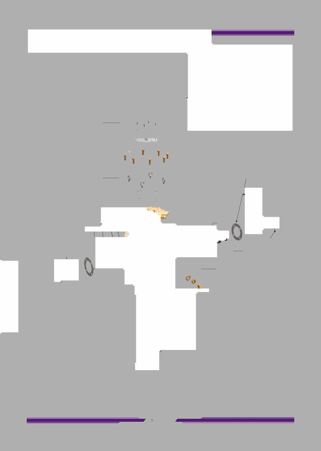
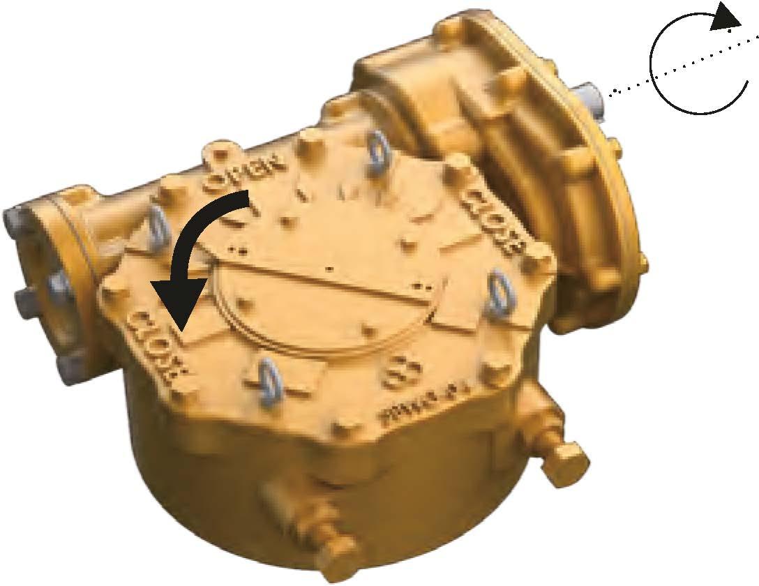
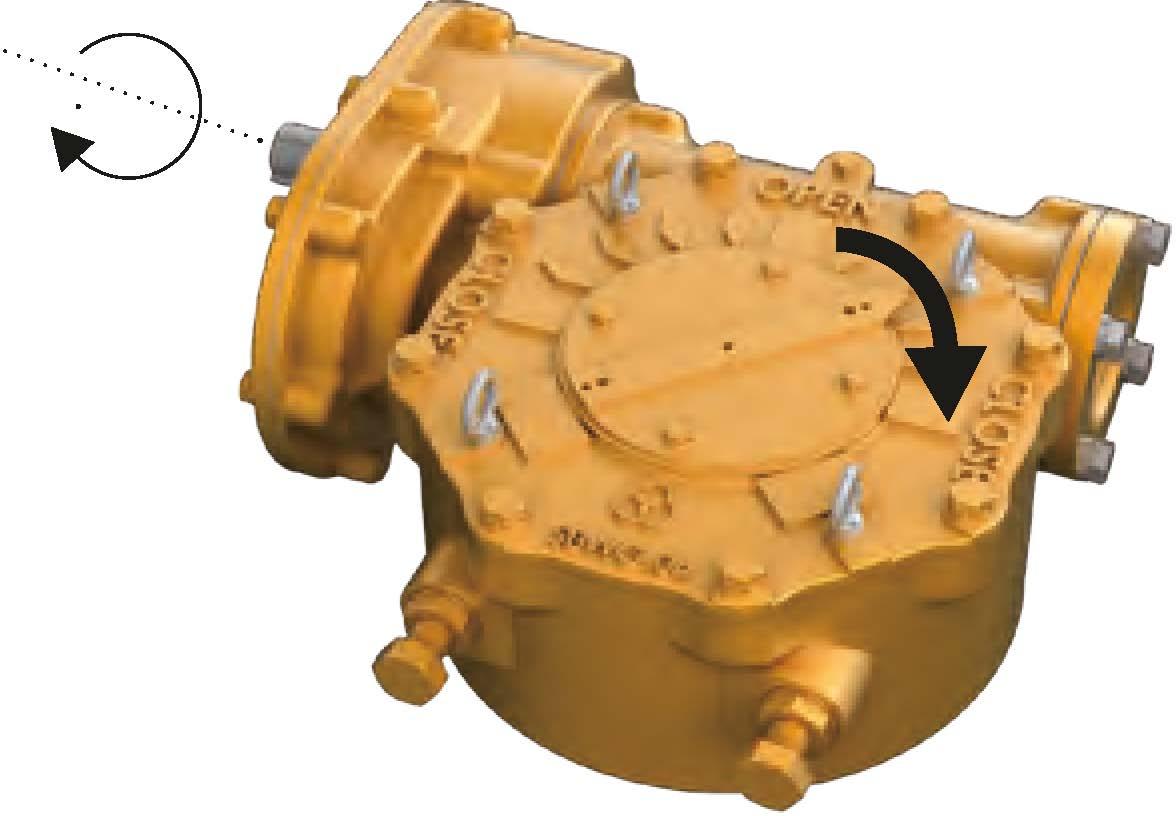
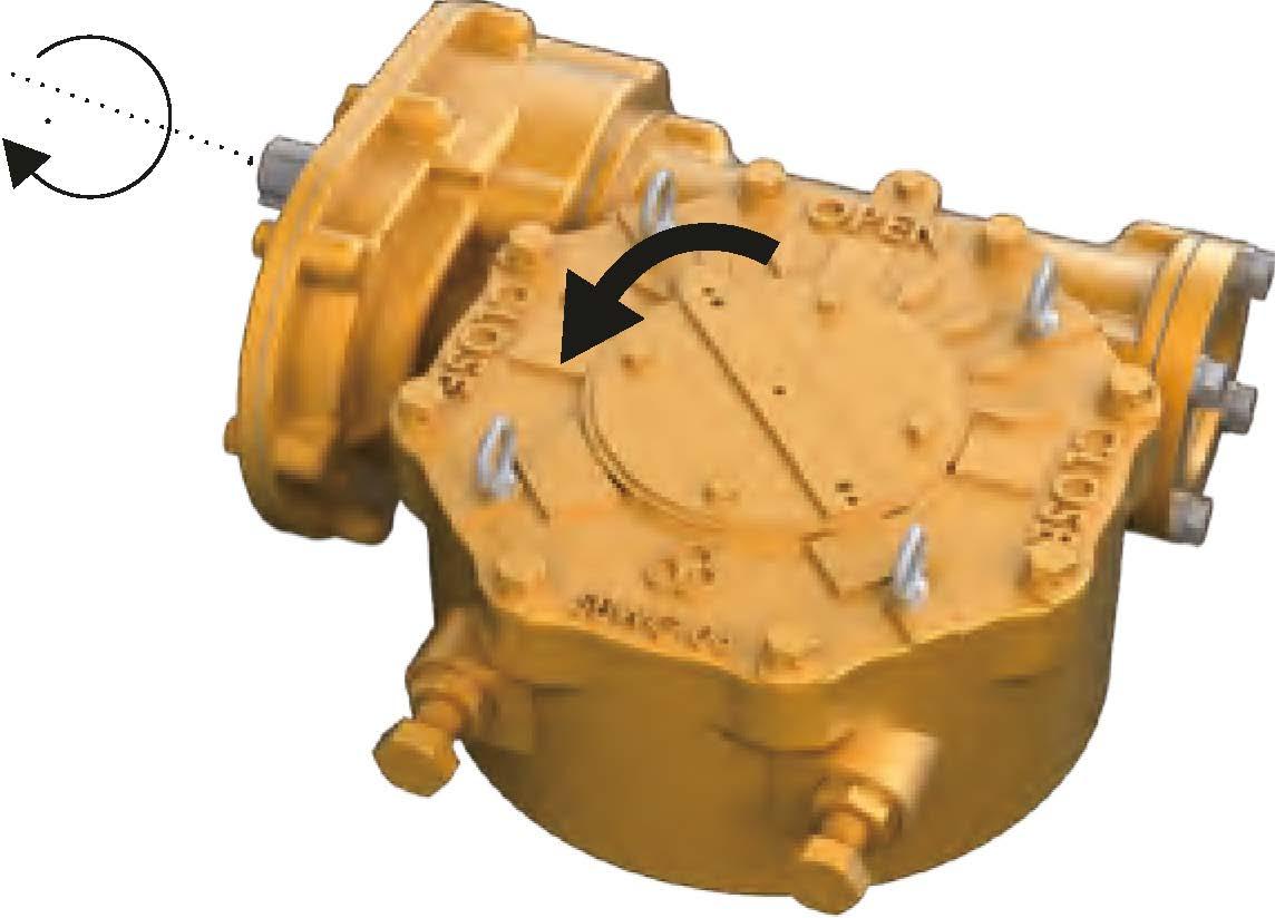
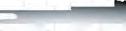
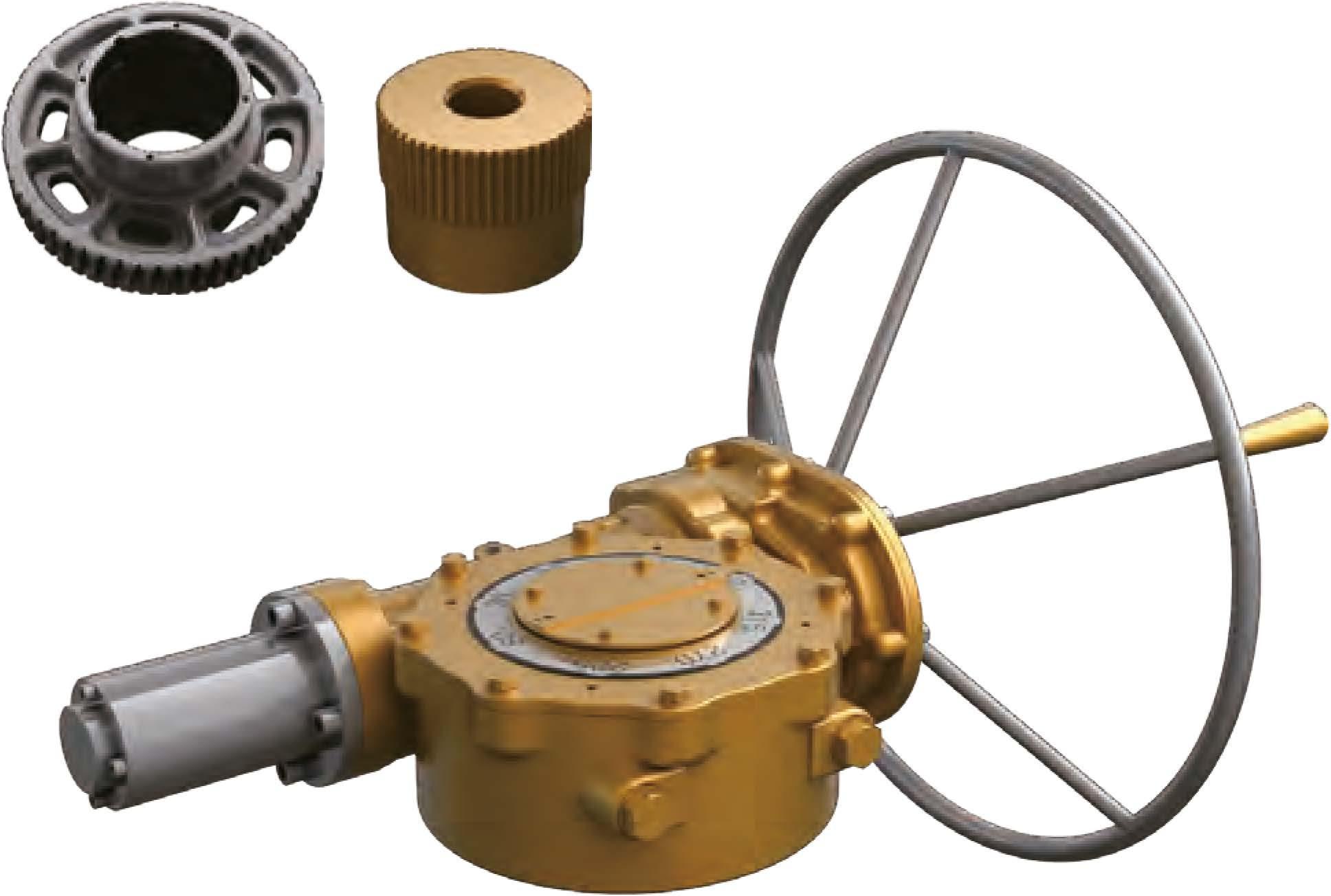
Assembly
1. Turn gear box to see bottom side.
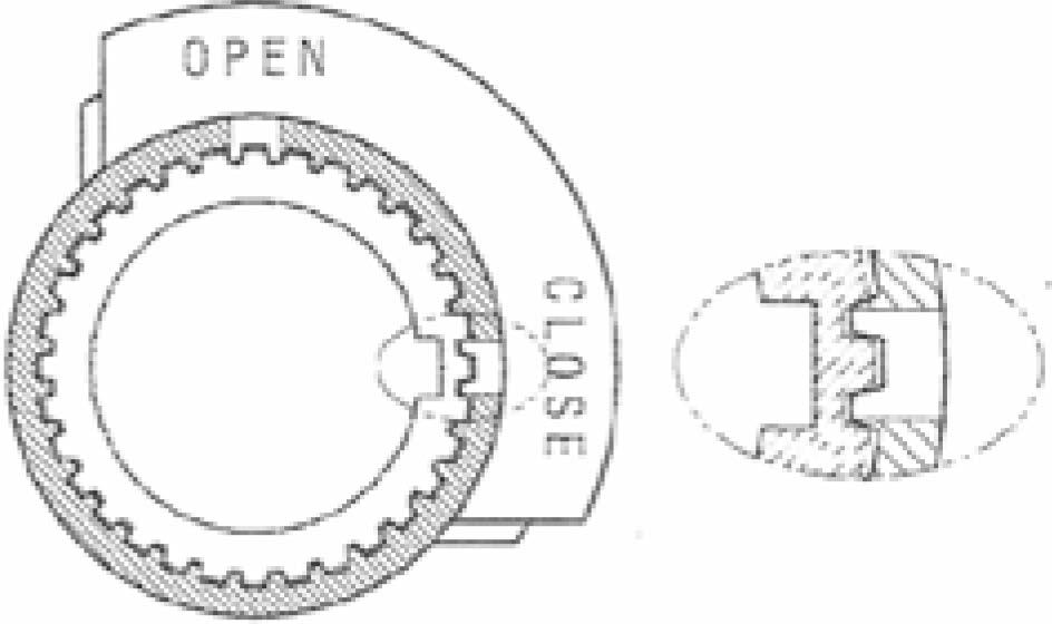
2. Insert bush correctly into the worm gear. Insert bush into grooves of worm gear. (IYlatch groove and bushing key in a straight line.) There is 2 grooves at bottom of worm gear. One groove is for open and the other is for close.
3. Fix spring.
CAUTION
• In case of bushing insert, match groove of worm gear and bushing key correctly.
• This groove is marked the position of Caution "close" or "open".
• If it does not match, the position may not be proper.
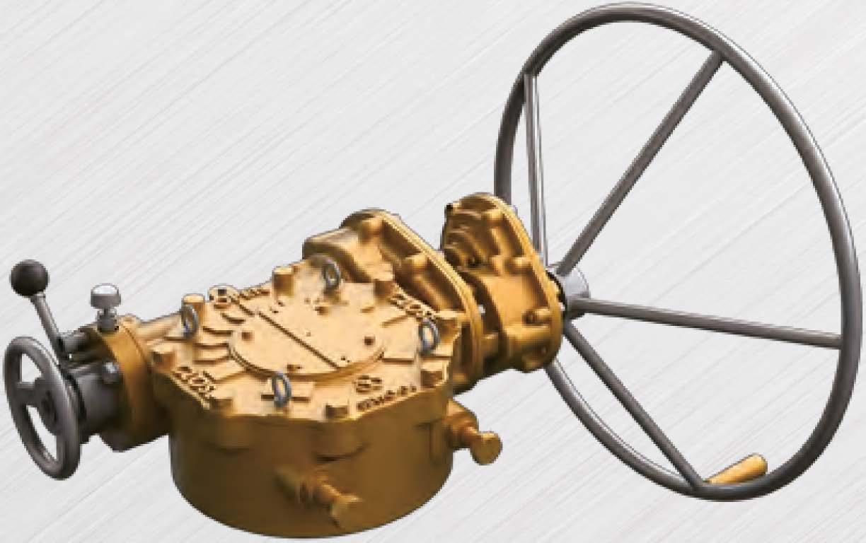
There are two input shafts in the below support actuator type. One Shaft is for high speed and the other shaft is for low speed.
Provides maximum mechanical advantage for seating and unseating of valves.
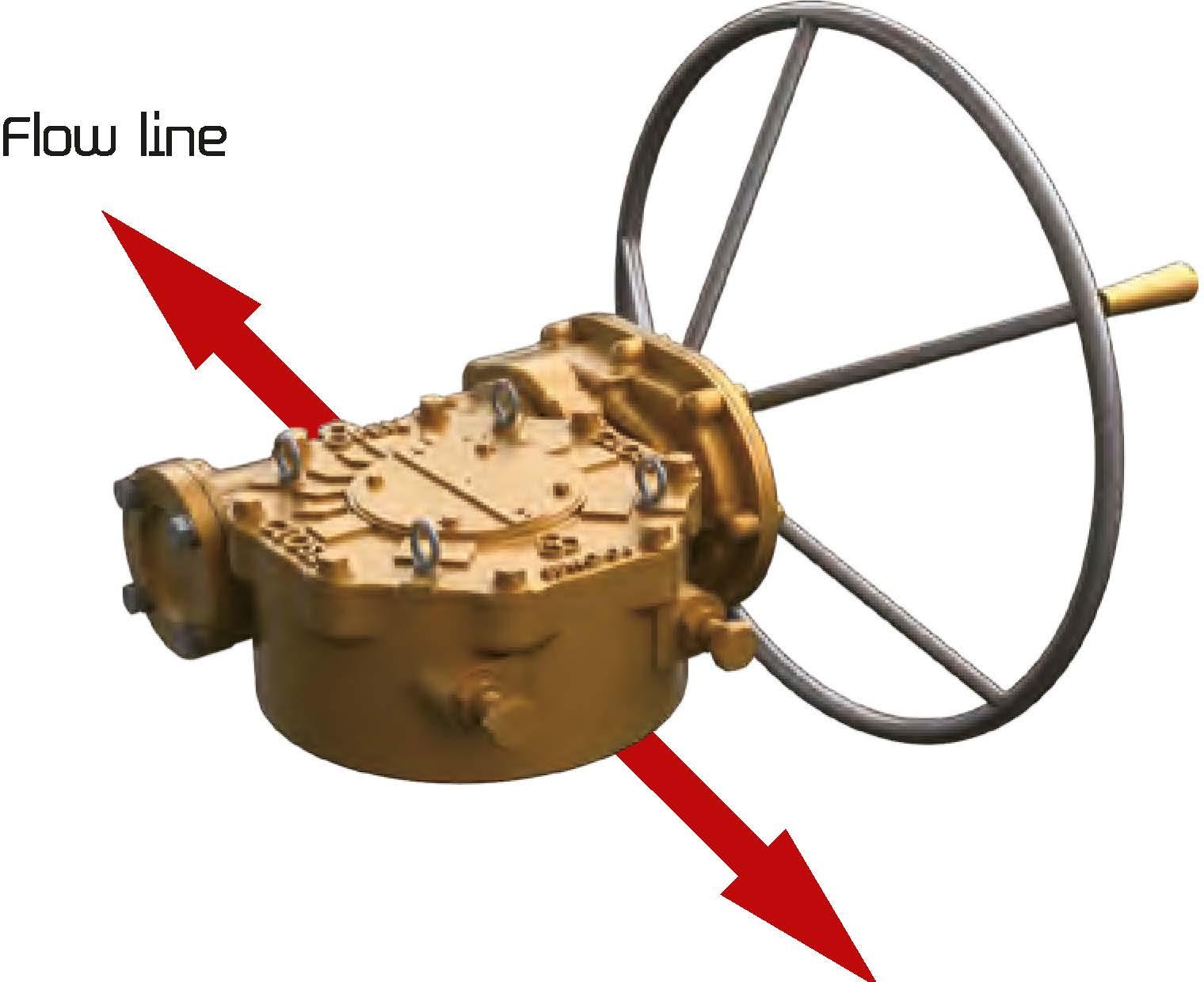
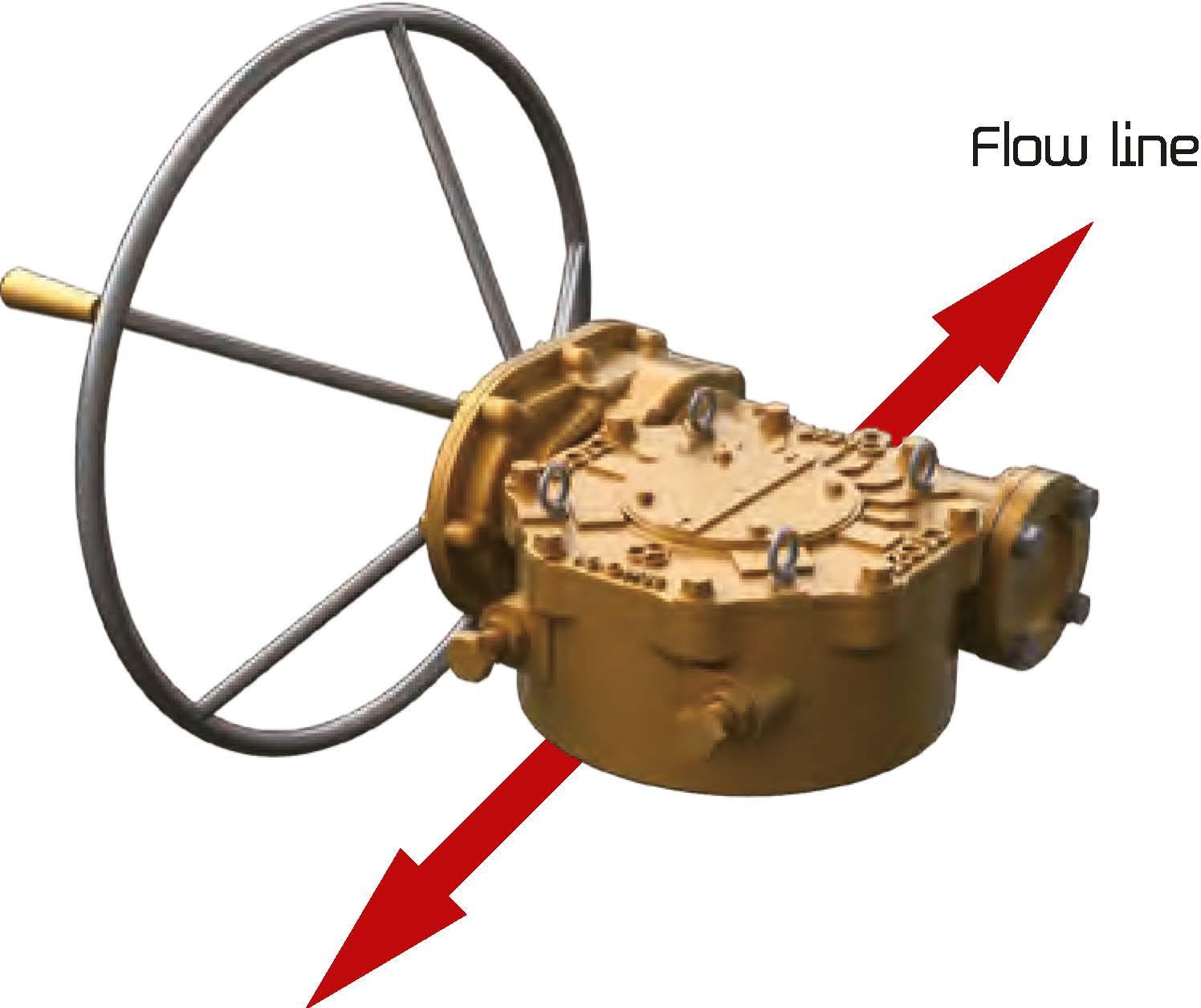
Allow for less turns after valve has been unseating. Input/OutputShaftRotationOptions>>>
Right Hand Input


Size and component specitication in this catalogue are subject to change without prior notice for
• IYlark has been changed and updated.
• All mounting bases conform to ISO 5210/1 standards.
• All castings are ductile iron, Class 65-45-12 excellent strength and impact resistance.
• Worm gear material is available in two option.
- Ductile iron.Class 80-55-06
- Aluminum bronze, B148-[95800
• Worm is 1045 heat treated Carbon steel.
• Removable splined bushing to permit accurate positioning between gear drive and valve stem.
• Options include hand wheels, chain and etc.
Worm Gear can be provided with IYlotor actuator input flanges to accept standard ISO IYlounting Base.
Splines permit accurate alignment of valve stem key.
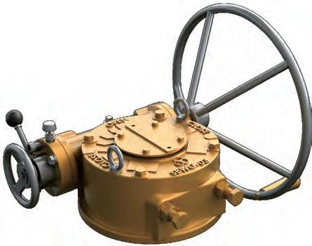
Input can be equipped with a Handwheel locking device for IYlanually operatedunits.
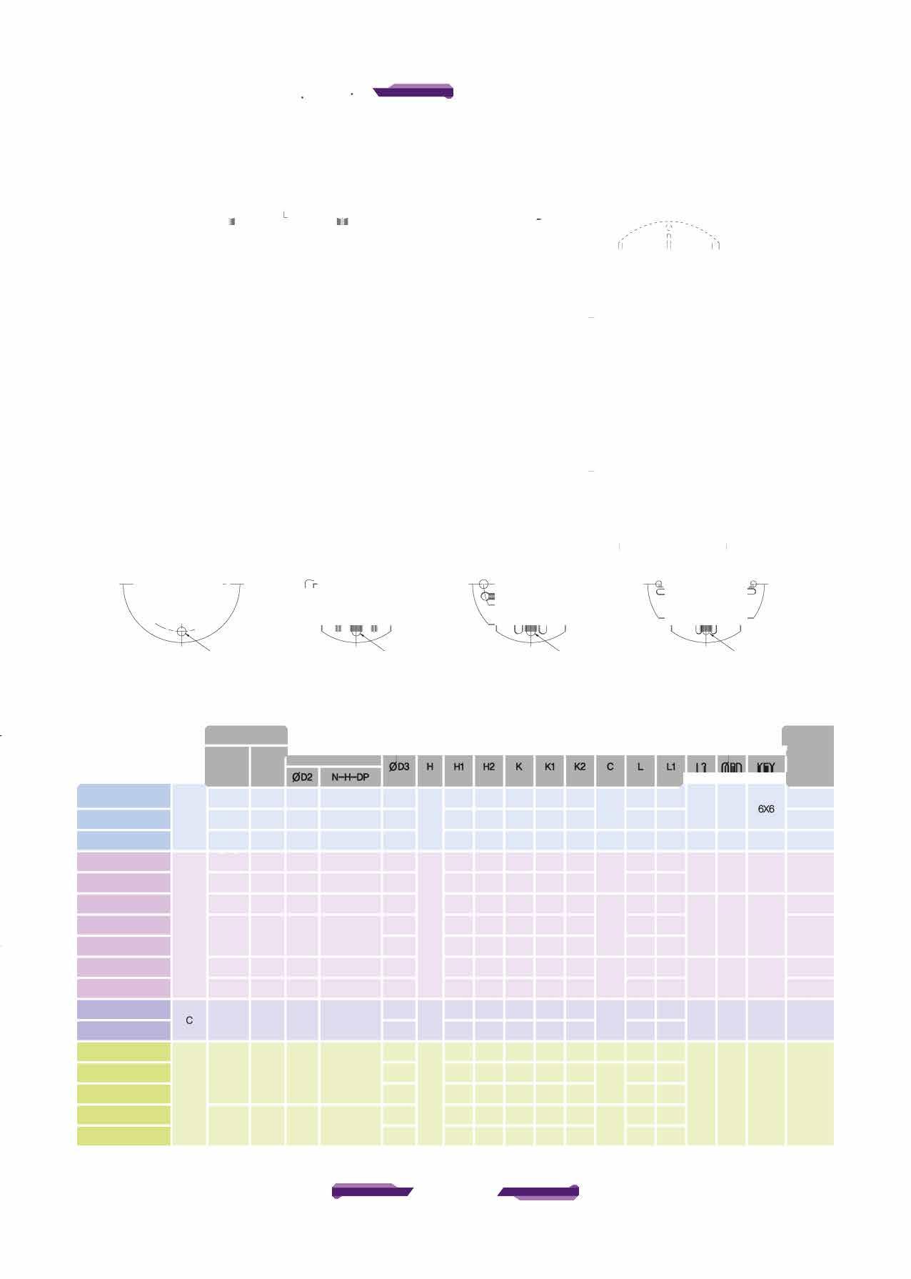
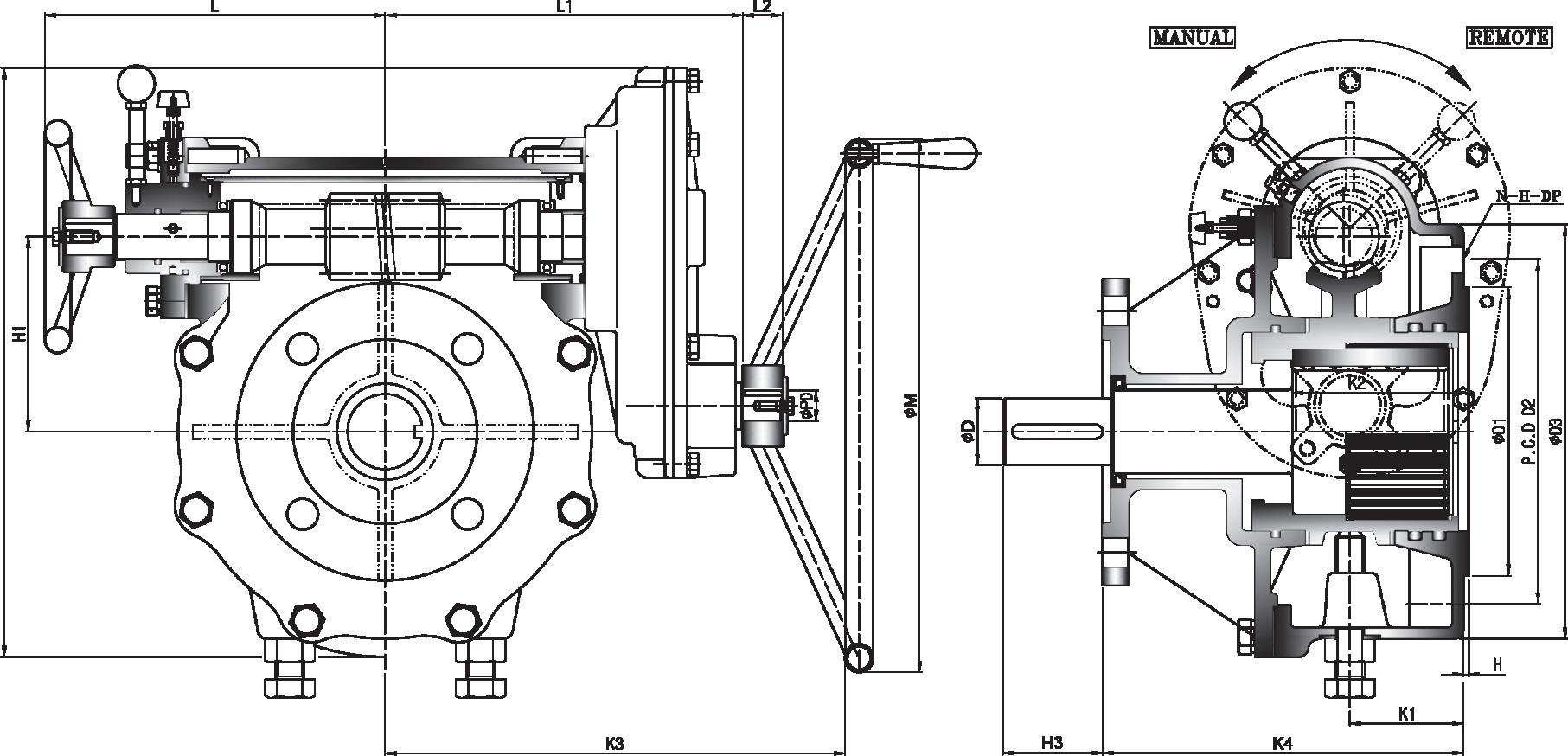
SBWG-35 52:1 80(22X14) F-16,(F-20),F-25
* SBWG--05 60:1 115(32X18) (F-20), F-25,F-30


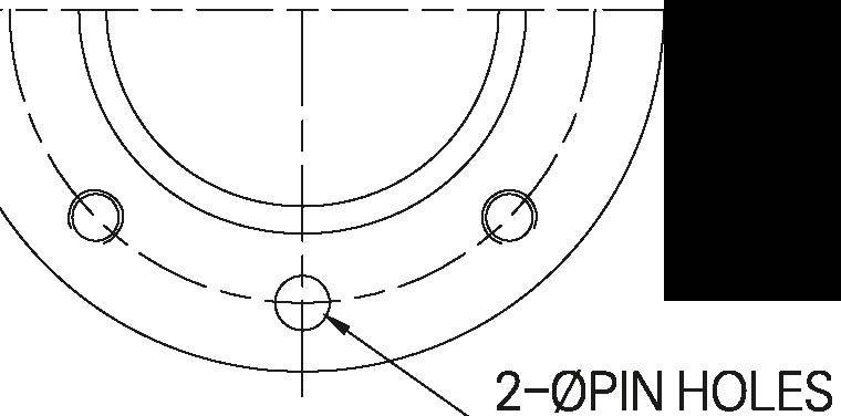
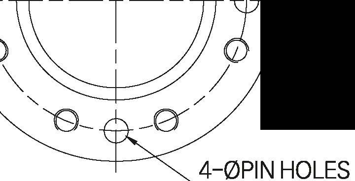
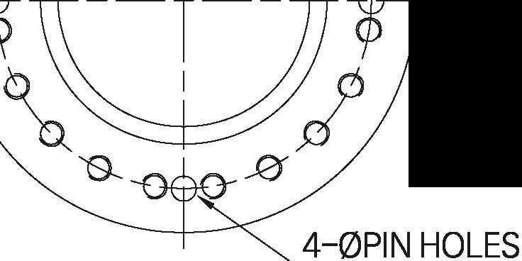
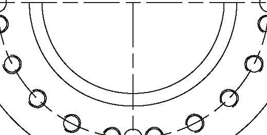
•Pin hole size is same as tap out diameter 1�T--/ I / 'a 0 / 2-(l)PIN HOLES

S&MHJ0-1S F-12 85
SBW<HJHS A F-14 100
SBW<Hl2-1S F-16 130
SBW<Hl3-1S F-16 160 (F-20)
SBWG-35-1S F-25 200
SBWG--04-1S F-25 200
*
SBW<HJS--1S B F-30 230
SBWG-55-1S
SBW<Hl6-1S F-35 260
SBW<Hl7-1S F-40 300
SBWG-75-1S F--48 370
SBWG--08-1S �1S
SBWG-10-1S F-60 470
SBWG-11-1S D
*
*
Size and component specitication in this catalogue are subject to change without prior notice for
improvement. • IYlark has been changed and updated.
• All mounting bases conform to ISO 5210/1 standards.
• All castings are ductile iron, Class 65-45-12 excellent strength and impact resistance.
• Worm gear material is available in two option.
- Ductile iron.Class 80-55-06
- Aluminum bronze, B148-[95800
• Worm is 1045 heat treated Carbon steel.
• Removable splined bushing to permit accurate positioning between gear drive and valve stem.
• Options include hand wheels, chain and etc.

Splines permit accurate alignment of valve stem key.
Input can be equipped with a Handwheel locking device for IYlanually operated units.

•Pin hole size is same as tap out diameter 1�T--/ I / 'a 0 /
SBWG-00-15T F-12 85
SBWG-OHST A F-14 100
SBWG-02--15T F-16 130
SBWG-03-15T F-16 160 (F-20)
SBWG-35-15T F-25 200
SBWG-Q4-15T F-25 200
*
SBWG---05-15T B F-30 230
SBWG-55-15T
SBWG-06-15T F-35 260
SBWG-07-15T F---40 300
SBWG-75-15T F-48 370
SBWG-08-15T
SBWG-09-15T
SBWG-10-15T F--60
SBWG-11-15T D
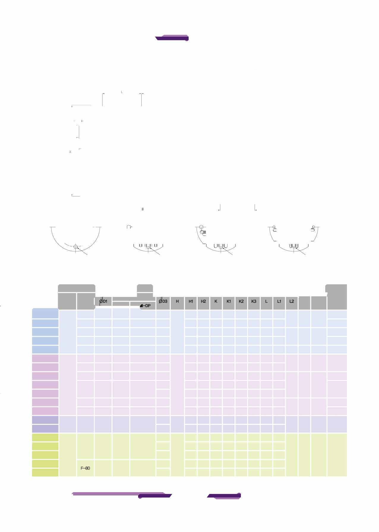
*SIMG-12--15T F--80
*SIMG-13-15T
Size and component specitication in this catalogue are subject to change without prior notice for

• All mounting bases conform to ISO 5210/1 standards.
• All castings are ductile iron, Class 65-45-12 excellent strength and impact resistance.
• Worm gear material is available in two option.
- Ductile iron.Class 80-55-06
- Aluminum bronze, B148-[95800
• Worm is 1045 heat treated Carbon steel.
• Removable splined bushing to permit accurate positioning between gear drive and valve stem.
• Options include hand wheels, chain and etc.
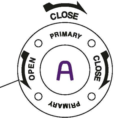
CW-CLOSE Bushing Type Splines permit accurate alignment of valve stem key.
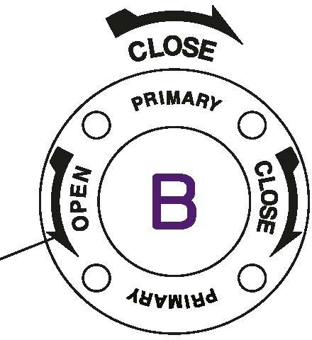
A. Primary Input Shaft (High Speed Input Shaft) Allow for less turns after valve has been unseating.
B. Second Input Shaft (Low Speed Input Shaft) Provides maximum mechanical advantage for seating and unseating of valves.

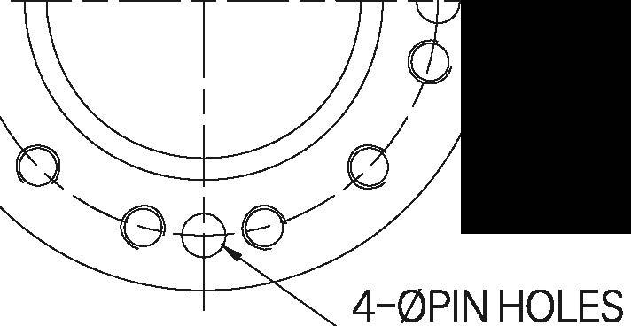
Pin hole size is same as tap out diameter
SBWCHXl-1SD F-12 85
SBWCHlHSD A F-14 100
SBWCHl2-1SD F-16 130
SBWCHl3-1SD F-16 160 (F-20)
SBWG-35-1SD F-25 200
SBWG---04-1SD F-25 200
*SBWCHl5-1SD B F-30 230
SBWG--55-1SD
SBWCHl6-1SD F-35 260
SBWCHl7-1SD F---40 300
SBWG-75-1SD F-48 370
SBWCHl8---1SD
SBWCHl9-1SD
SBWG-10-1SD F--60 470
SBWG-1HSD D *SBWG-12-1SD
Size and component specitication in this catalogue are subject to change without prior notice for
• IYlark has been changed and updated.
• All mounting bases conform to ISO 5210/1 standards.
• All castings are ductile iron, Class 65-45-12 excellent strength and impact resistance.
• Worm gear material is available in two option.
- Ductile iron.Class 80-55-06
- Aluminum bronze, B148-[95800
• Worm is 1045 heat treated Carbon steel.
• Removable splined bushing to permit accurate positioning between gear drive and valve stem.
• Options include hand wheels, chain and etc.

Splines permit accurate alignment of valve stem key.
Worm Gear can be provided with IYlotor actuator input flanges to accept standard ISO IYlounting Base.
Input can be equipped with a Handwheel locking device for IYlanually operated units.
SBWG-35--1SD 333.7:1 80(22X14) F-16,(F-20),F-25
SBWG--04-1SD 504:1 95(25X14) F-16,(F-20) F-25 10400 7671 *SBWG--05-1SD 540:1 115(32X18) (F-20), F-25,F-30 15900 11727
SBWG-55-1SD 558:1 125(32X18) F-25,F-30 23500 17333
SBWG--06-1SD 1024:1 140(36X20) F-25, F-30,F-35 32800 24192
SBWG-07-1SD 1088:1 180(45X25) F-30,F-35, F--40 51100 37689
SBWG-75-1SD 1650:1 210(50X28) F-35,F--40, F-48 81500 60111
SBWG--08-1SD

•Pin hole size is same as tap out diameter
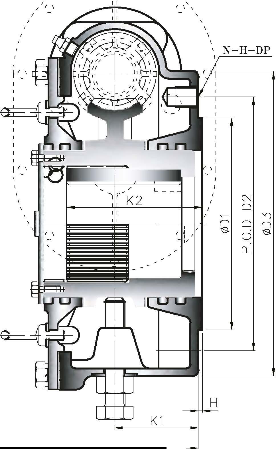
1�T--/ I / 'a 0 / 2-(l)PIN HOLES TYPE -A
FLANGE 0D1
SBW(H)()-1SDT F-12 85
SBW<H>HSDT A F-14 100
SBW<Hl2-1SDT F-16 130
SBW<Hl3-1SDT F-16 160 (F-20)
SBWG-35-1SDT F-25 200
SBWG---04-1SDT F-25 200
*�"ISJT B F-30 230
SBWG-55-1SDT
S8'MHJ6-1SDT F-35 260
SBW<Hl7-1SDT F-40 300
SBWG-75-1SDT F-48 370
SBWG--08-1SDT
SBWCHl9-1SDT
SBWG-10-1SDT F-60 470
SBWG-1HSDT D
*SIMG-12-1SIJr F--00 670
*SIMG-13-"ISJT
Size and component specitication in this catalogue are subject to change without prior notice for
• IYlark has been changed and updated.
• All mounting bases conform to ISO 5210/1 standards.
• All castings are ductile iron, Class 65-45-12 excellent strength and impact resistance.
• Worm gear material is available in two option.
- Ductile iron.Class 80-55-06
- Aluminum bronze, B148-[95800
• Worm is 1045 heat treated Carbon steel.
• Removable splined bushing to permit accurate positioning between gear drive and valve stem.
• Options include hand wheels, chain and etc.
CW-CLOSE Bushing Type Splines permit accurate alignment of valve stem key.
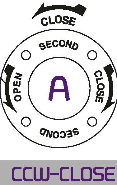
A. Primary Input Shaft (High Speed Input Shaft) Allow for less turns after valve has been unseating.
B. Second Input Shaft (Low Speed Input Shaft) Provides maximum mechanical advantage for seating and unseating of valves.

• Pin hole size is same as tap out diameter 1�T - -/ I / o d / 2-IZlPIN HOLES
SEMG-00-2SD F-12 85
SEMG-01-2SD A F-14 100
SB,\G-02-2S[) F-16 130
$Y,G-()3-2S[) F-16 160 {F-20)
SIMG-35-2SD F-25 200
SEMG-04-2SD F-25 200
•SEW3-05-2SD B F-30 230
S:MG-55-2SD
S:MG--06-2SD F-35 260
SEMG-07-2SD F--40 300
SIMG-75-2SD F-48 370
SBMHll-2SD
SJ,\G-00-2S[)
SIMG-10-2SD F-60 470
SIMG-11-2SD D
•SIMG-12-2SD
• All mounting bases conform to ISO 5210/1 standards.
• All castings are ductile iron, Class 65-45-12 excellent strength and impact resistance.
• Worm gear material is available in two option.
- Ductile iron.Class 80-55-06
- Aluminum bronze, B148-[95800
• Worm is 1045 heat treated Carbon steel.
• Removable splined bushing to permit accurate positioning between gear drive and valve stem.
• Options include hand wheels, chain and etc.
Splines permit accurate alignment of valve stem key.
Worm Gear can be provided with IYlotor actuator input flanges to accept standard ISO IYlounting Base.
Input can be equipped with a Handwheel locking device for IYlanually operated units.
*SB\',G-05-ZSD 1368:1 115(32X18) (F-20), F-25,F-30 15900 11727
SBWG-55-280 1413.6:1 125(32X18) F-25,F-30 23500 17333
SBW<Hl6-2SD 3072:1 140(36X20) F-25, F-30,F-35 32800 24192
SBWG-07-280


•Pin hole size is same as tap out diameter
Size and component specitication in this catalogue are subject to change without prior notice for quality improvement. • IYlark has been changed and updated.
• All mounting bases conform to ISO 5210/1 standards.
• All castings are ductile iron, Class 65-45-12 excellent strength and impact resistance.
• Worm gear material is available in two option.
- Ductile iron.Class 80-55-06
- Aluminum bronze, B148-[95800
• Worm is 1045 heat treated Carbon steel.
• Removable splined bushing to permit accurate positioning between gear drive and valve stem.
• Options include hand wheels, chain and etc.
Splines permit accurate alignment of valve stem key.
Worm Gear can be provided with IYlotor actuator input flanges to accept standard ISO IYlounting Base.
Input can be equipped with a Handwheel locking device for IYlanually operated units.

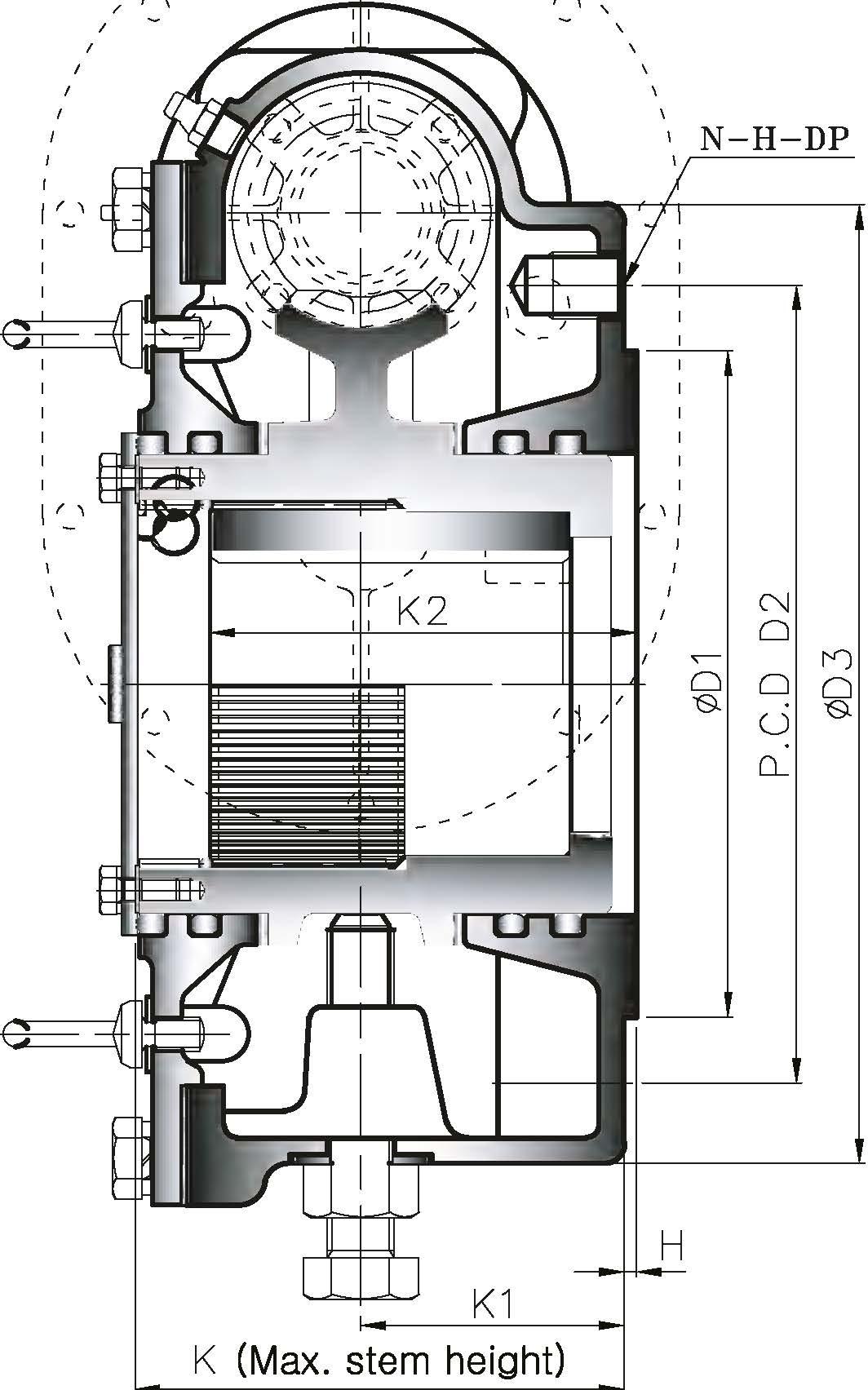
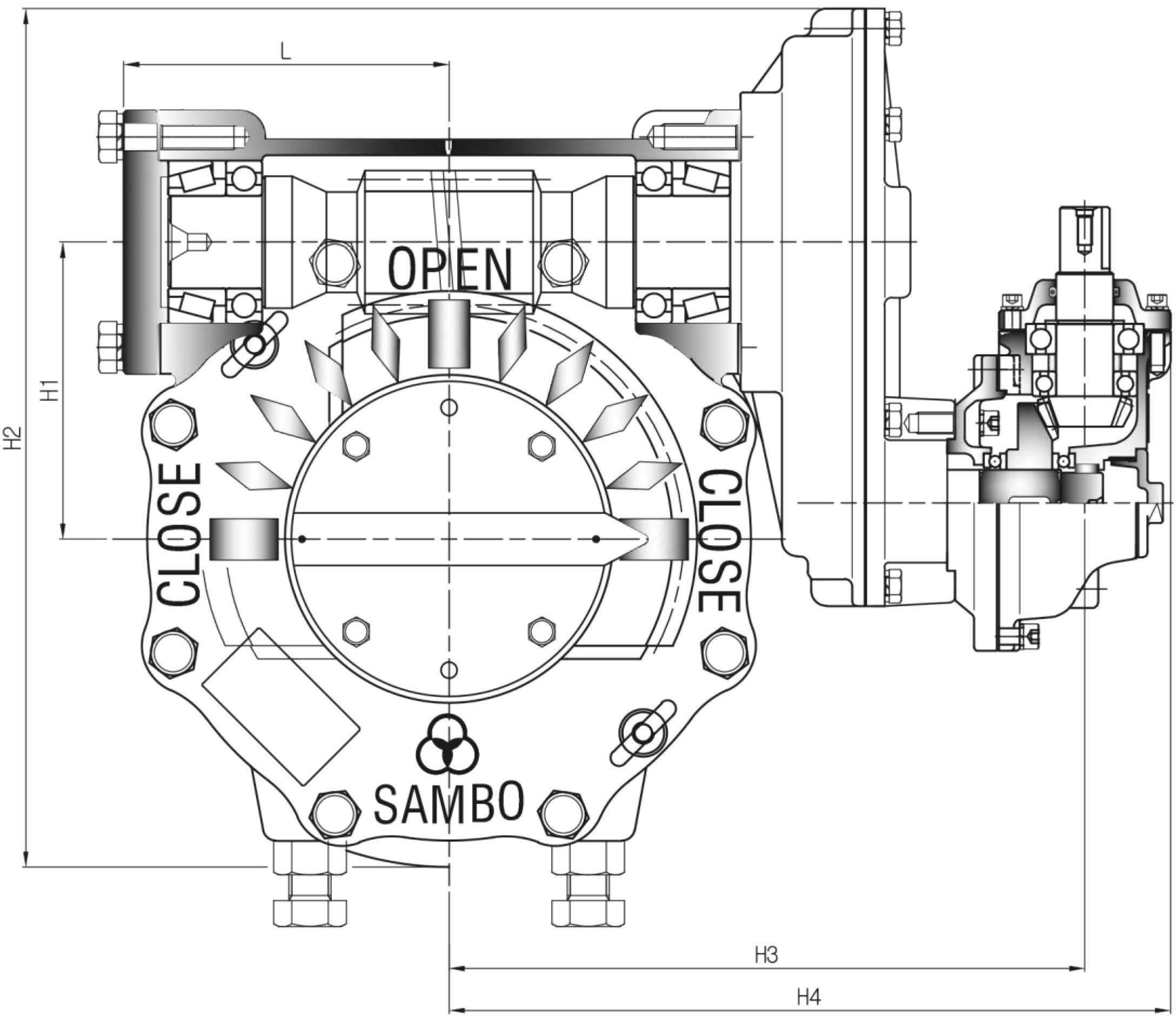
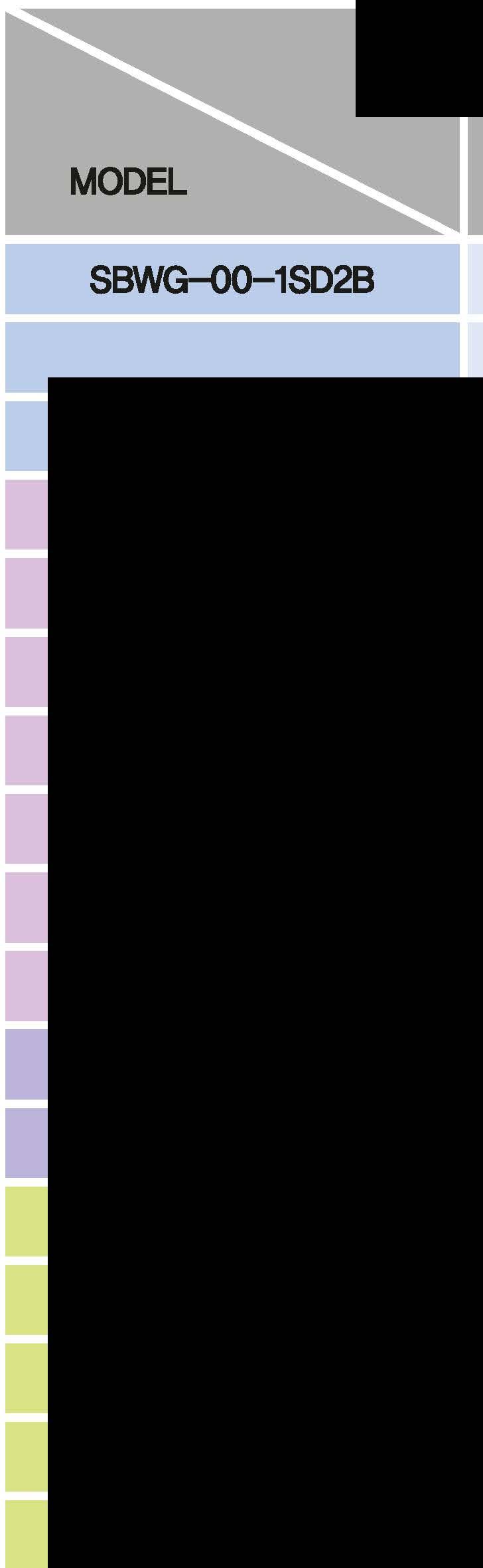
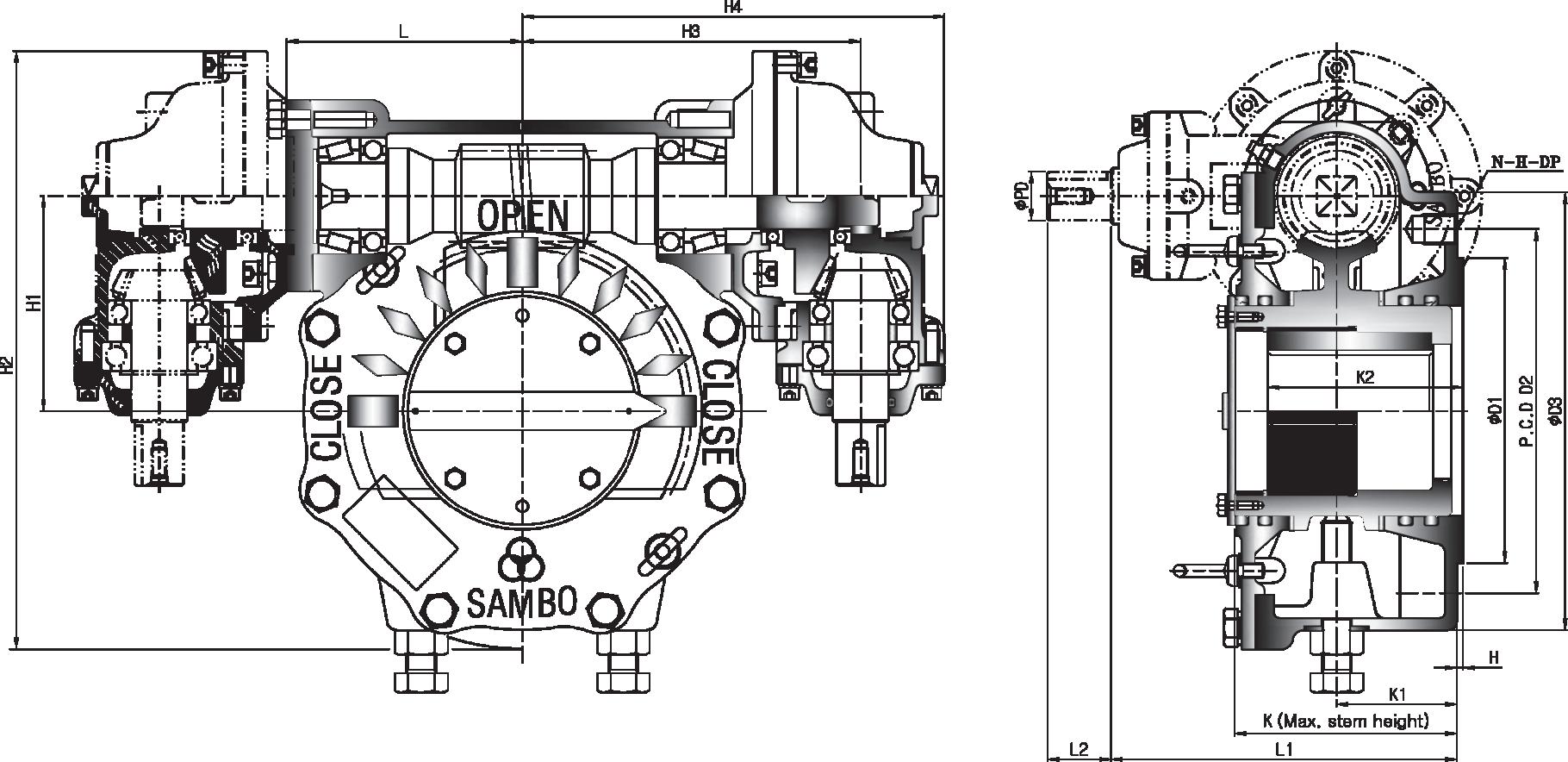
H3 H4
•Pin hole size is same as tap out diameter
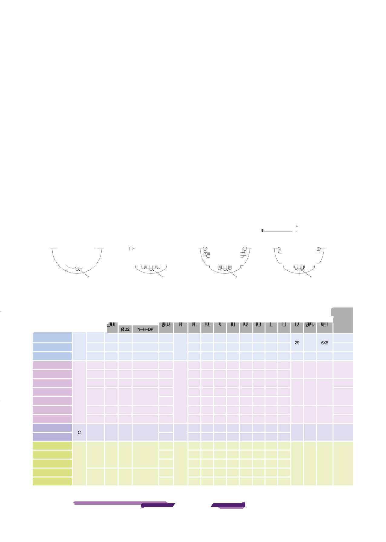
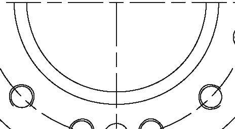
SBWG--00-1SD28 F-12 85 125 4-M12-18 165
SBWG--01-1SD28 A F-14 100 140 4-M1&-24 190 2
SBWG--02-1SD28 F-16 130 165 4-M20-30 220
SBWG--03-1SD2B F-16 160 205 &-M1&-24 250 (F-20)
SBWG-35-1SD28 F-25 200 254 &-M1&-24 300
SBWG--04-1SD28 F-25 200 254 &-M1&-24 300
•SBWG--05-1SD2B B 350 3 F-30 230 298 8-M20--30
SBWG-55-1SD2B 350
SBWG--06-1SD28 F-35 260 356 &-M30---45 415
SBWG--07-1SD28 F-40 300 406 &-M3&-55 475
SBWG-75-1SD2B 560 F-48 370 483 12-M36---55 5
SBWG--08-1SD2B
SBWG--09-1SD28
SBWG-10-1SD28 F--60 470 603 20-M3&-55 800
SBWG-11-1SD2B D 900 5
•SBWG-12-1SD28 1000 F--60 670 813 20-M42--63
•SBWG-13-1SD28
Size and component specitication in this catalogue are subject to change without prior notice for quality improvement. • IYlark has been changed and updated.
• All mounting bases conform to ISO 5210/1 standards.
• All castings are ductile iron, Class 65-45-12 excellent strength and impact resistance.
• Worm gear material is available in two option.
- Ductile iron.Class 80-55-06
- Aluminum bronze, B148-[95800
• Worm is 1045 heat treated Carbon steel.
• Removable splined bushing to permit accurate positioning between gear drive and valve stem.
• Options include hand wheels, chain and etc.
Splines permit accurate alignment of valve stem key.
Worm Gear can be provided with IYlotor actuator input flanges to accept standard ISO IYlounting Base.
Input can be equipped with a Handwheel locking device for IYlanually operated units.
SBWG-35-1SD2B 667:1 80(22X14) F-16,(F-20),F-25 6100 4499
SBWG--04-1SD28 1260:1 95(25X14) F-16,(F-20),F-25 10400 7671
•SBWG--05-1SD28 1350:1 115(32X18) (F-20),F-25,F-30 15900 11727
SBWG-55-1SD2B 1395:1 125(32X18) F-25,F-30 23500 17333
SBWG--06-1SD28 3072:1 140(36X20) F-25, F-30,F-35 32800 24192
SBWG--07-1SD28 3264:1 180(45X25) F--30,F-35,F--40 51100 37689
SBWG-75-1SD28 6600:1 210(50X28) F--35,F--40, F--48 81500 60111
6600:1

• All mounting bases conform to ISO 5210/1 standards.
• All castings are ductile iron, Class 65-45-12 excellent strength and impact resistance.
• Worm gear material is available in two option.
- Ductile iron.Class 80-55-06
- Aluminum bronze, B148-[95800
• Worm is 1045 heat treated Carbon steel.
• Removable splined bushing to permit accurate positioning between gear drive and valve stem.
• Options include hand wheels, chain and etc.
Splines permit accurate alignment of valve stem key.
Worm Gear can be provided with IYlotor actuator input flanges to accept standard ISO IYlounting Base.
Input can be equipped with a Handwheel locking device for IYlanually operated units.
•SBW<HlS--28 180:1 115(32X18) (F-20), F-25,F-30 15900 11727
SBWG-55-28 186:1 125(32X18) F-25,F-30


• All mounting bases conform to ISO 5210/1 standards.
• All castings are ductile iron, Class 65-45-12 excellent strength and impact resistance.
• Worm gear material is available in two option.
- Ductile iron.Class 80-55-06
- Aluminum bronze, B148-[95800
• Worm is 1045 heat treated Carbon steel.
• Removable splined bushing to permit accurate positioning between gear drive and valve stem.
• Options include hand wheels, chain and etc.
Splines permit accurate alignment of valve stem key.
Worm Gear can be provided with IYlotor actuator input flanges to accept standard ISO IYlounting Base.
Input can be equipped with a Handwheel locking device for IYlanually operated units.
SBWG-55-280 465:1 125(32X18) F-25,F-30

•Pin hole size is same as tap out diameter 1�T--/ I / a 0 /
2-0PIN HOLES TYPE-A
f!BNG-00-3/J F-12 85
S91',G-{)1-3N A F-14 100
f!BNG---Cfe-3N F-16 130
SBl,G-{)3-3/J F-16 160 (F--20)
SB,\G----35---3/J F--25 200
S91'.G---04-3N F--25 200
•SBWG---05-3W B F-30 230
'.:BNG----$-3N
f!BNG---00-3N F-35 260
fBNG---<Tl-3N F-40 300
SB,\G---7fr-3N C F---48 370
SB/,G---00--'1N
'i!BNG---00---3N
SB,\G-10-3N F--60 470
SB,\G-11-3/J D
•SB,\G--12-3N F-80 670 •SB,\G-13-3/J
4-0PINHOLES


Size and component specitication in this catalogue are subject to change without prior notice for
• All mounting bases conform to ISO 5210/1 standards.
• All castings are ductile iron, Class 65-45-12 excellent strength and impact resistance.
• Worm gear material is available in two option.
- Ductile iron.Class 80-55-06
- Aluminum bronze, B148-[95800
• Worm is 1045 heat treated Carbon steel.
• Removable splined bushing to permit accurate positioning between gear drive and valve stem.
• Options include hand wheels, chain and etc.
Splines permit accurate alignment of valve stem key.
Worm Gear can be provided with IYlotor actuator input flanges to accept standard ISO IYlounting Base.
Input can be equipped with a Handwheel locking device for IYlanually operated units.
SBWG--04-3W 2688:1 95(25X14) F-16,(F-20) F-25 10400 7671
•SBWG--05-3W 2880:1 115(32X18) (F-20), F-25,F-30 15900 11727
SBWG-55-3W 3224:1 125(32X18) F-25,F-30 23500 17333
SBWCHl6-3W 3328:1 140(36X20) F-25, F-30,F-35 32800 24192
SBW<Hl7-3W 3536:1 180(45X25) F-30,F-35, F--40 51100 37689
f!BNG-75-3W 3696:1 210(50X28) F-35,F--40, F-48 81500 60111
SBWG-08-3W


• All mounting bases conform to ISO 5210/1 standards.
• All castings are ductile iron, Class 65-45-12 excellent strength and impact resistance.
• Worm gear material is available in two option.
- Ductile iron.Class 80-55-06
- Aluminum bronze, B148-[95800
• Worm is 1045 heat treated Carbon steel.
• Removable splined bushing to permit accurate positioning between gear drive and valve stem.
• Options include hand wheels, chain and etc.
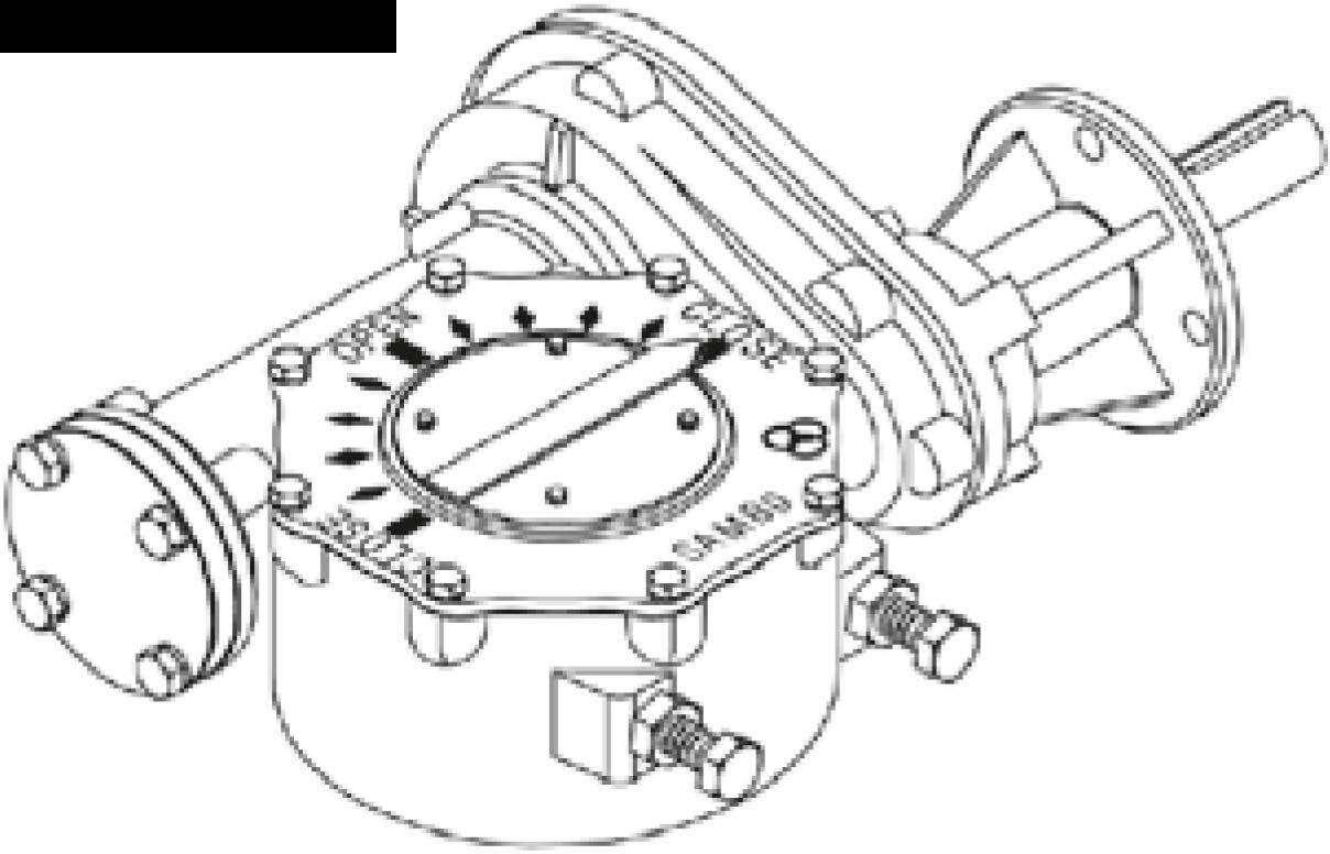
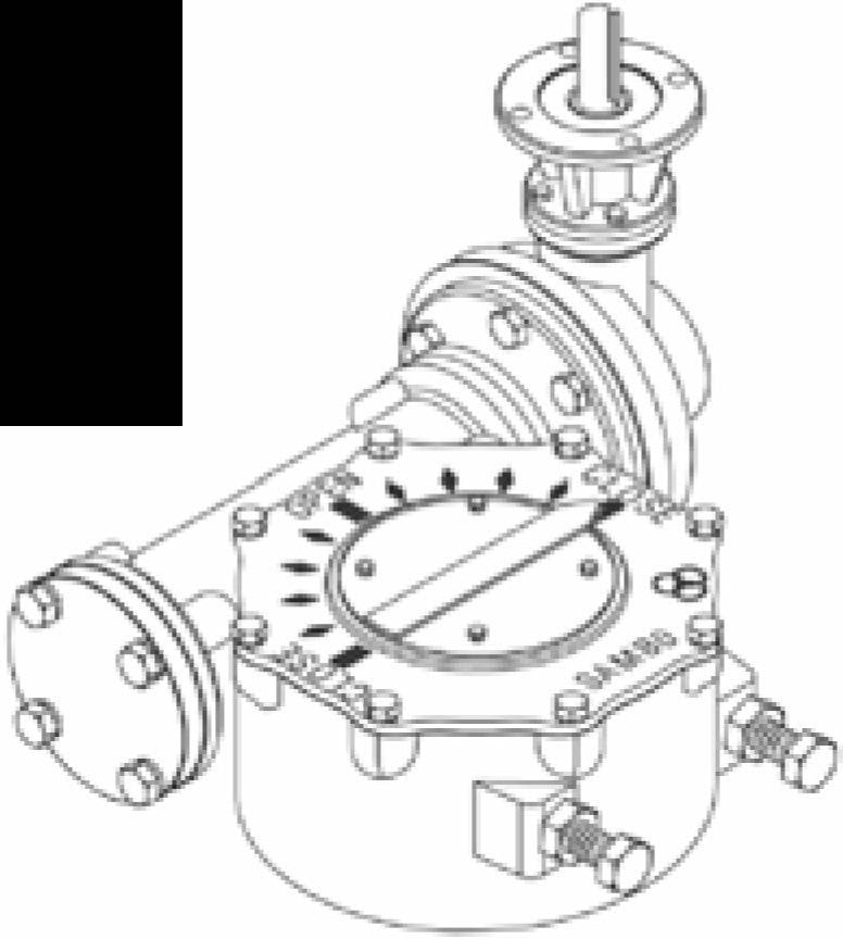
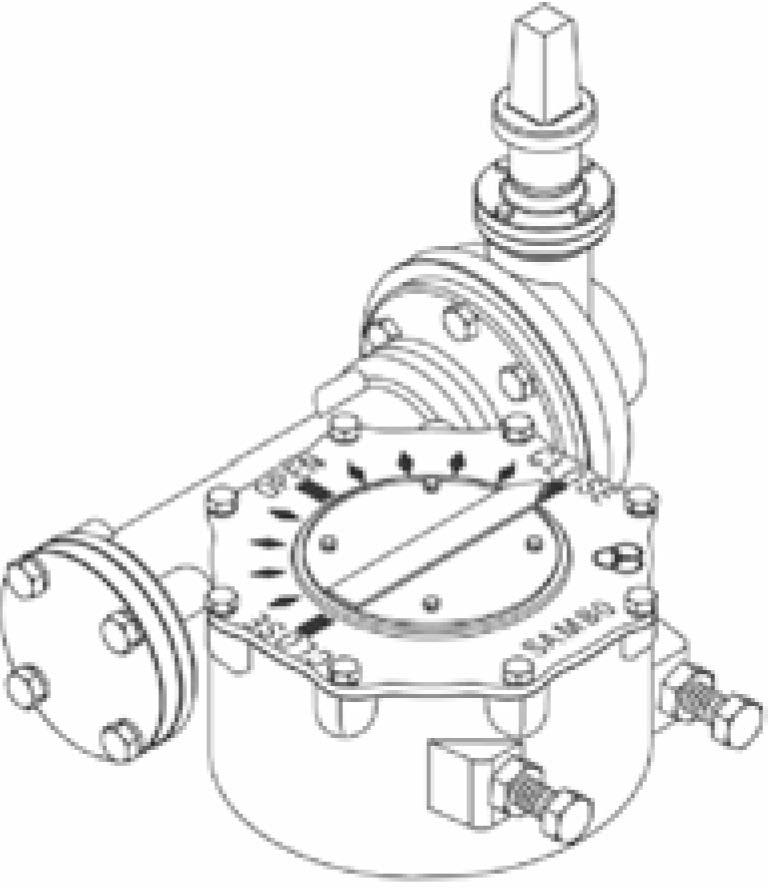
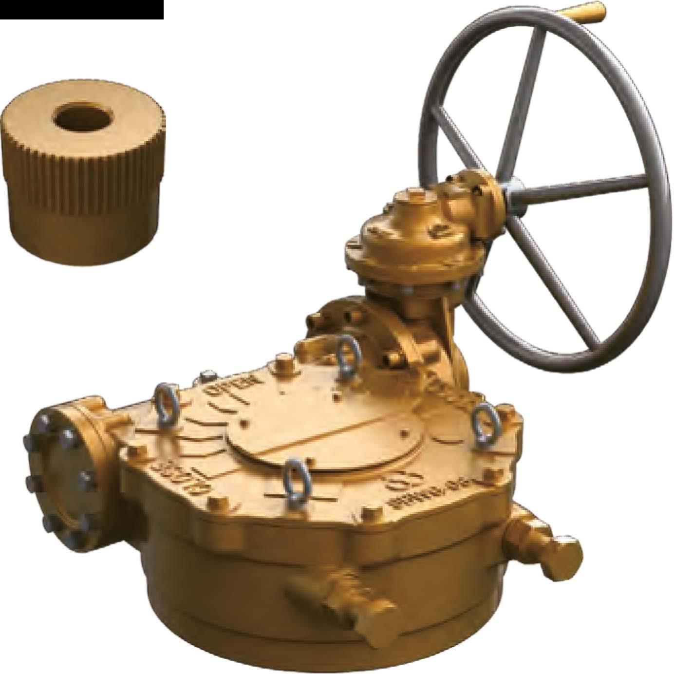
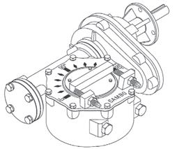
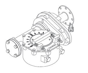
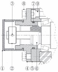
• If worm gear actuators are supplied on a value, the end stops are already set.
• In case end stops need to be adjusted set end position OPEN first, if the exact end position of the value can not be seen through a position marking at the value shaft, the setting may have to be done with the value removed.
Splines permit accurate alignment of valve stem key.
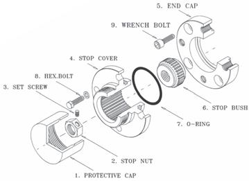
• Remove all bolts@ at stop cover@
• Turn value manually to end position OPEN.
• In case stop cover.@ do not correspond to the threads of the housing. Take off the stop covers.@ and place it in the required positon.
• Fit bolts@ withe washers and fasten them euently.
• Finally, protective cap<D remove, turn stop nut� to adjust end position CLOSE.


Contact your local CDC sales representatives:
Serving OH, MI, W.PA, WV, E.KY, VA

143 S.Thomas Rd. Tallmadge, OH 44278
Tel: 330-253-4800
Email: sales@portersvilleprd.com
7707 Cole Lane Midland MI 48642
Tel: 586-764-4336
Email: sales@portersvilleprd.com
www.portersvilleprd.com
2680 New Butler Rd. New Castle, PA 16101
Tel: 724-368-8725
Email: sales@portersvilleprd.com
700 Southlake Blvd. North Chesterfield VA 23236
Tel: 804-593-2384
Email: sales@portersvilleprd.com

1500 E. Burnett St. Signal Hill, CA 90755
Tel: 562-424-8108
Email: Sales@BV-BM.com
www.bv-bm.com
403 Technology Dr South Point, OH 45680
Tel: 740-377-0012
Email: sales@portersvilleprd.com

3800 Fruitvale Avenue Bakersfield, 93308
Tel: 661-589-6801
Email: Sales@BV-BM.com
3195 Park Road, Benicia, CA 94510
Tel: 707-590-6688
Email: Sales@BV-BM.com