


This catalog is provided to aid in the proper selection of a Farris 3800 Series.
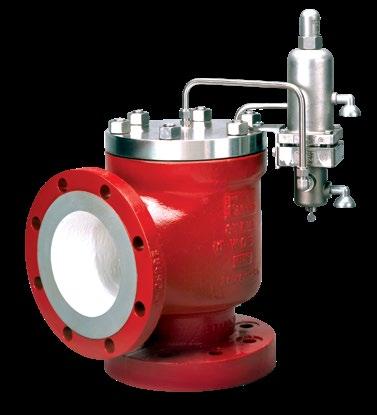
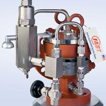
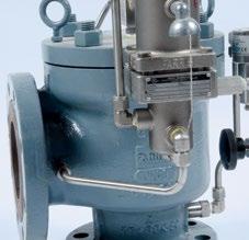
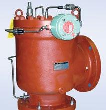
Farris’ 3800 Series valves feature an innovative, integrally cast, flanged body with a semi-nozzle design. Series 3800 valves are self-contained units actuated by either the snap-acting or modulating style pilot controls. Valves in this series are certified under Section VIII of the ASME Code for Air, Gas, Vapor, Steam and Liquid Service.
3800 Series valves are available in API Orifice sizes D through T as well as full port models. Series 3800 valves offers raised face or ring joint inlet flanges from 150 through 2500 ASME classes with 150, 300 and selected 600 class outlets. Standard options support applications in pressures range from 15 to 6170 psig with temperatures of -450°F to 450°F. For higher temperature and pressure requirements, please consult the Factory.
All Series 3800 valves have non-flowing pilot controls. Standard materials of construction include a carbon steel main valve body with 316 stainless steel trim and all 316 stainless steel pilot control. The main valve is also available in optional materials in a full 316 stainless steel, NACE, Monel®, Hastelloy®, Duplex with other materials available upon request.
Viton® soft goods are standard in both pilot control and main valves. Buna-N, neoprene, ethylene propylene, silicone, PTFE and Kalrez® soft goods are available as options; contact Factory for more information.
Sizing software and support is available at http://www.cw-valvegroup.com/SizeMaster Viton and Kalrez are registered trademarks of
All products manufactured by Farris Engineering are warranted free of defects in material and workmanship when used within the range recommended for a period of one year after installation or eighteen months from delivery. When authorized, any defective product may be returned to the factory and if found defective will be repaired or replaced free of charge, solely at the discretion of Farris Engineering, ex-works our factory. No charge for labor or other expense incurred will be allowed, as the liability of Farris Engineering is measured by the refund price of the defective product only. All warranties are based on the product being used within the range recommended and does not cover damages or defects due to normal wear and tear, misuse, alteration or neglect. The purchaser shall determine the suitability of the product for use and assumes all risks and liabilities in connection therewith.
This warranty does not cover the performance of valves tested at site on test equipment that is not to the same technical standard as that used by the manufacturer.
Type of Actuation
to 740 (1.03 to 51.03)
Range °F (°C) -50 to 500 (-45 to 260)
-450 to -51 (-267 to -46)
Ethylene Propylene (EPDM) -65 to 250 (-54 to 121)
Nitrile (Buna) -55 to 225 (-48 to 107)
Soft Goods (O-Rings) °F (°C) Fluorocarbon (Viton) -20 to 450 (-29 to 232)
Aflas -20 to 450 (-29 to 232)
Kalrez 0 to 500 (-18 to 260)
Kalrez Steam 212 to 500 (100 to 260) ü
All PORVs use soft goods for their seats and seals. In selecting a soft good, please note the following guidelines:
• The main valve and pilot control soft goods selection is based on meeting the set pressure and temperature ranges shown as well as being chemically compatible with the process fluid.
• The soft goods selected should not exceed the above limits. For most applications both the operating and relieving temperatures should fall within the ranges shown. Where the sole relieving scenario is external fire, the relieving temperature may be ignored as long as the operating temperature falls within the range of the elastomer selected.
• Because of the wide variety of fluids and process conditions used in the process industry, it is the customer’s responsibility to select the proper soft goods material for each specific application.

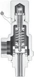
The pilot control valves use system pressure to keep the main valve closed. System pressure is transmitted through the pressure pickup from the inlet of the main valve, through the pilot control and into the dome of the main valve. The system pressure exerts force upon the top of the piston in the dome, holding the piston firmly against the seat on the nozzle in the main valve. The surface area of the piston in the dome of the main valve is greater than the seat area, so the greater the system pressure, the greater the force holding the piston onto the main valve seat. As a result, the pilot operated relief valve gets tighter as the system pressure approaches set pressure.
As system pressure reaches set pressure, the force acts upon the surface area of the pilot control disc, overcoming the spring force in the pilot valve, and the pilot valve lifts. As the seat assembly in the pilot control begins to lift, it seals off the flow of pressure to both the vent and the main valve dome. At the same time, the pressure in the dome is released through the pilot vent. Once the pressure in the main valve’s dome has been released, the system pressure, acting on the bottom of the piston, will lift the piston and relieve system pressure until normal process conditions are restored.
At the point where the system pressure blows down, the spring force in the pilot control overcomes the force of system pressure acting on the pilot control seat assembly, closing the upper seat and reopening the lower seat. This re-establishes flow through the pilot control, allowing system pressure to be redirected back into the main valve dome, closing the main valve. Blowdown can be precisely adjusted externally by raising or lowering the blowdown adjuster position in the pilot control.
Bubble-tight closer to set pressure: Series 3800 valves operate bubble-tight at higher operating pressure to set pressure ratios, allowing operators to run very close to the system’s maximum allowable working pressure. While protecting the system from overpressure, Series 3800 allows maximum product throughput, increased system profitability, and reduced fugitive emissions.
Unaffected by back pressure: Unlike a direct spring loaded valve, the pilot operated valve’s set pressure is not affected by back pressure. The pilot control valve, isolated from the influence of downstream pressure, controls the main valve’s opening and closing.


At normal operating system pressure, the modulating control performs the same as the snap acting control. The pressure pickup directs system pressure from the inlet of the main valve through to the pilot control inlet port and into the dome of the main valve. The pressure area of the piston in the dome of the main valve is greater than the nozzle seat area. The greater the system pressure, the greater the seating force holding the main valve piston onto the nozzle seat.
As system pressure increases and approaches the valve’s set pressure, the force acting upward on the pilot control increases, overcoming the spring force of the pilot control causing the inlet seat to lift and seal against the floating spool. Pressure is maintained in the dome because the inlet and outlet seals remain closed.
Any further incremental increase in system pressure near set pressure raises both the inlet seat and spool causing the outlet seat seal to crack open. This allows a partial venting of dome pressure in the event of an increase in system pressure. Similarly, any further decrease in system pressure near set pressure lowers both the inlet seat and spool causing the outlet seat seal to close. This allows for a re-pressurizing of the dome when the inlet seat opens at decrease in system pressure.
As the system pressure increases to set point, the modulating action of the pilot control, as described above, reduces the pressure in the main valve dome. The further decrease in dome pressure caused by increasing system pressure reduces the seating force to zero and opens the main valve seat to allow flow. The opening of the main valve responds gradually and proportionally to the rise in system pressure, either at or above the set pressure. The main valve will achieve full open and rated flow by 10% overpressure.
As the system pressure is decreased below set pressure, the spring force in the modulating pilot control overcomes the system pressure acting on the diaphragm/piston assembly and re-closes the outlet seat. The inlet seat then opens and allows system pressure back into the main valve dome, reseating the main valve.
A pilot valve with a modulating control has the same operating advantages as a snap acting pilot control: operates bubble-tight close to set pressure and is unaffected by back pressure.
Minimizes product losses: In addition, the modulating control responds gradually and proportionately to the rise in over pressure, minimizing product losses and reducing reaction forces when the flow requirement is below the maximum rated flow of the valve.
Modulating Valve – Closed Position
Modulating Valve – Partially Open Position

Modulating Valve – Fully Open Position

To simplify the selection and specifying of Farris pressure relief valves, use the following type numbering system. The type numbering system is ideal as the digits which comprise a specific type number have a distinct significance. The digits describe the basic valve series, orifice, seat and internal construction, inlet temperature range, body, and spring material, inlet flange class as well as Code liquid design.
*For set pressures above 1480 psig, main seat seal for all valves with 900#, 1500# and 2500# inlet flanges use PTFE.
****Use for cyrogenic applications, S4 special material suffix is not required. 4 6
**Required for steam services
To properly process your order and avoid delay please specify the following:
1. Quantity
2. Inlet and Outlet Size
3. Farris Type Number*
4. Inlet and Outlet Flange Class and Facing
5. Materials of Construction, if other than Standard
6. O-Ring Seal Material (Viton is Standard)
7. Set Pressure*
8. Maximum Inlet Temperature*
9. Allowable Overpressure*
10. Fluid and Fluid State*
General Notes:
*For temperature ranges down to -50F, specify LB, to -55F specify LC under special materials
* **Required for steam services
Backpressure, Superimposed Constant and/or Variable and Built-up*
Required Capacity*
13. Physical Properties of Fluid (Molecular Weight, Specific Gravity, etc.)*
14. Accessories, if any required such as:
a)Manual or Remote Depressurizing
b)Field Test Connection
c)Reverse Flow Preventer
d) Auxiliary Filter
e) Any other
15. Code Requirements, if any required
*If you would like Farris to verify your selection and sizing, this information is required.
If valve modification or set pressure changes are required, consideration must be given to correct the nameplate and other data.
Designation ASME Nominal Inlet Flange Class
L Liquid Service (Standard Connections)
X Air & Vapor Service (Oversize Connections)
Y Liquid Service (Oversize Connections)
D Air & Vapor Service (Dual Outlet)*
E Liquid Service (Dual Outlet)*
U Air & Vapor Service (Non-Standard API Connections)
N Air & Vapor Service (Non-Standard API Connections) 1 Raised Face, ASME Std. (125 to 160 AARH) 9 Ring Joint ASME Std. (Octagonal)
H 63 to 83 AARH Raised Face (Inlet only)
Although not applicable to the inlet facing only, the following first digit letters are also used:
J 63 to 83 AARH (Outlet only)
K 63 to 83 AARH (Inlet and outlet)
X High Pressure Hub Connection*
5 Field Test Connection
6 Reverse Flow Preventer
7 Pressure Spike Snubbers
8 Remote Depressurizing
F Field Test Connection with Indicator
R Remote Sensing
V Pilot Control Discharge Connected to Main Valve Outlet
*Available on 6" and 8" inlet size valves only. Other sizes consult factory
*Limited valve sizes and pressure classes. Consult factory. See table below for combinations
Valves: If an exact replacement valve is required, the valve type, size and serial number must be specified to assure proper dimensions and material being supplied. If a specific valve has become obsolete, a recommendation for the current equivalent, if any, will be made.
Spare Parts: When ordering parts, use part names as listed in the bills of material in this catalog. Specify valve type, size and serial number. If serial number is not available, the original Farris factory order number will assist in our supplying the proper part and material.
Springs: Order as an assembly to include spring with upper and lower spring buttons. Specify valve type, size, serial number, set pressure and back pressure, if any.
* For Modulating Controls, Field Test Connection w/ Indicator (F) is automatically supplied, unless specified otherwise. 2 X -
NACE
NACE
M4* Complete Monel
H4* Complete Hastelloy C
D4* Duplex St. St.
D8* Super Duplex St. St.
LB* Low temperature carbon steel - LCB Body
LC* Low temperature carbon steel - LCC Body
*Add "N" for NACE E.g. M4N, H4N,
for Common
Combinations 9 Four Auxiliary Functions: Options 4, 5 or F*, 6 & 8
Combo – Auxiliary Filter (3) & Field Test Connection (5 or F)*
(6)
C Designation for combinations of options not listed
5
Threaded Convertible Design: the unique convertible design minimizes the number of components and maximizes their interchangeability, reducing parts inventories and overall costs.
Convertible Nozzle: threaded convertible nozzles can be removed and replaced easily without factory service. They can be installed with common tools while the valve is in line, saving time and money.
Fewer Internal Components: the valve design requires no lift stops and the main valve opens fully at set pressure. The orifice area is controlled by the nozzle, eliminating the need for additional parts to restrict lift.
One Piece Body: integrally cast flanges assure the highest material integrity and eliminate problems that may occur with welding.
Full Port Option: the full port option provides maximum capacity per inlet size.
General Notes:
1. Part used on 3" inlet sizes and larger.
2. Materials certified in compliance with NACE specifications.
3. PTFE for seals required in main valve for temperatures below -20°F. Consult the Factory.
4. PTFE used for Main Seat Seal (item 12) for all valves with 900#, 1500#, and 2500# inlet flanges.
Main Valve Soft Seat: unlike metal seated valves which require costly machining and lapping procedures, the main valve soft seat is easily maintained and repaired.
Less Weight, Lower Profile: system pressure provides the seating force in pilot operated relief valves so pilot valves are smaller in size and weight than direct spring loaded valves.
Full 316 Stainless Steel Trim: this trim is standard and includes nozzle, piston, retainer and guide for long and versatile service life.
Suitable for NACE Service: for high quality materials of construction that meet NACE MR0103 or MR0175/ISO 15156 service, refer to N1 trim for carbon steel body and N4 trim for stainless steel.
5. We reserve the right to substitute comparable fluorocarbon materials.
6. EPDM is standard offering for NACE; other materials can be selected. Please specify at time of order
7. Graphite reinforced PTFE with stainless steel spring.
Inconel is a registered trademark of Inco Alloys International, Inc.
Snap-Acting, Non-Flowing: the PCF5 and PCL pilot controls are snap acting and non-flowing, minimizing the flow of process media through the pilot for reduced fugitive emissions and extended valve life.
Full 316 Stainless Steel Construction: resists corrosion and extends the life and versatility of the PCF5 and PCL controls.
Adjustable Blowdown: allows setting blowdown at 3% of set pressure so that product loss is minimized and fugitive emissions reduced.
Viton Seats and Seals: these chemical-resistant seals and seats enhance a control's life. Neoprene, ethylene propylene, silicone, and Buna-N soft goods are optional and extend temperature ranges from -65°F to 450°F. Kalrez available when maximum resistance to chemical attack is required. Contact factory for more information.
Set Pressures and Blowdown Set at Pilot Control: in line service, settings and blowdown adjustments are completed quickly and easily without main valve intrusion. Subsequent reduction in product loss and fugitive emissions add to system profitability.
Accessory Options for Farris’ snap acting controls are outlined on pages 31-35 of this brochure.
1.
2.
3.
4.
Modulating, Non-Flowing: the PCM, PCMS and HPCM pilot controls are modulating and non-flowing, minimizing the flow of process media through the pilot for reduced fugitive emissions and extended valve life. Also suitable for 2-phase flow applications.
Full 316 Stainless Steel Construction: resists corrosion and extends the operation and versatility of the modulating control.
Fixed Blowdown: The modulating controls are a fixed blowdown pilot control with no external adjustment. Depending on fluid service, a blowdown of 3% to 6% is typical.
Viton Seats and Seals: have a wide spectrum of chemical compatibility and temperature range to meet most applications and enhance valve life. Buna-N and ethylene propylene soft goods are optional and extend temperature ranges from -65°F to 450°F. Contact the Farris factory for more information on other construction materials.
Set Pressure Set at Pilot Control: in-line service and setting adjustments are done quickly and easily without main valve intrusion. Subsequent reduction in product loss and fugitive emissions adds to the system’s profitability.
Accessory Options for Farris’ modulating pilot controls are outlined on pages 31-35 of this brochure.
General Notes:
1. Part
2. Materials certified in compliance with NACE specifications.
3. We reserve the right to substitute comparable fluorocarbon materials.
4. Part used on PCMS only.
5. Part used on HPCM only.
6. EPDM is standard offering for NACE; other materials
7. Graphite
Modulating, Non-Flowing: the HPCM7 pilot control is modulating and non-flowing, minimizing the flow of process media through the pilot for reduced fugitive emissions and extended valve life.
Full 316 Stainless Steel Construction: resists corrosion and extends the operation and versatility of the modulating control.
HPCM7 Modulating Pilot Control is available on valves with 1500 & 2500 class inlet flanges extending the set pressure range of modulating controls from 2220 up to 6170 psig.
Fixed Blowdown: The modulating controls are a fixed blowdown pilot control with no external adjustment. Depending on fluid service, a blowdown of 3% to 6% is typical.
Viton Seats and Seals: have a wide spectrum of chemical compatibility and temperature range to meet most applications and enhance valve life. Buna-N and ethylene propylene soft goods are optional and extend temperature ranges from -65°F to 450°F. Contact the Farris Factory for more information on other construction materials.
Accessory Options for Farris’ modulating pilot control are outlined on pages 31-35 of this brochure.
General Notes:
1. Standard elastomer is Viton which is suitable to a maximum temperature of 450°F. For temperatures above 450°F the o-ring seals must be specified as Kalrez.
2. The 300# and 600# flanges have identical drilling with flange thickness equal to the 600# class.
3. For liquid service applications, add “L” to the end of the base type number for valves with standard size connections. Change the “X” to a “Y” for valves with oversize connections and change “D” to an “E” for valves with dual outlet. Examples: 38FC10L-120, 38FC10Y-120, 38TC10E-120.
General Notes Continued:
(506)
(563)
General Notes:
1. Standard elastomer is Viton which is suitable to a maximum temperature of 450°F. For temperatures above 450°F the o-ring seals must be specified as Kalrez.
2. The 300# and 600# flanges have identical drilling with flange thickness equal to the 600# class.
3. Valves only certified for air, gas, vapor and steam service.
4. Valves with ring joint inlet connections available. Consult the Factory for final dimensions.
5. A 1" x 2" valve with an “G” orifice is only available when configured with a remote sensing option.
General Notes:
1. Capacities at 30 PSIG and below are based on 3 PSI
using the
using
K for air, gas, and steam service is 0.859.
General Notes:
1. Capacities at 30 PSIG and below are based on 3 PSI overpressure.
2. For sizing purposes the coefficient of discharge, K for air, gas, and steam is 0.801.
3. Full port orifices require that inlet piping have a flow area equal to or greater than the full port orifice flow area.
General Notes:
1. Capacities at 30 PSIG and below are based on 3 PSI overpressure.
2. For sizing purposes the effective coefficient of discharge, K d for liquids is 0.869 when sizing using the API effective areas. When sizing using the ASME actual areas, the certified coefficient of discharge K for water is 0.782.
3 Values in this table assume no backpressure.
1518.928.346.770.4110180257399504607893154622413648 2021.332.052.879.61242032914515706871009174825334124 3025.638.463.395.41492443485416828231209209430354940 4029.544.373.11101722814026247889501396241835045704 5033.049.581.712319231545069888110621561270339186377 6036.254.389.513421034549276596511641710296242926986 7039.158.696.7145227372532826104212571847319946367546 8041.862.7103155243398569883111513441975342049568067 9044.366.5109165258422603937118214252095362752568556 10046.770.1115174272445636987124615022208382455419019 15057.285.814121333354577912091526184027054683678611046 20066.199.116324638463090013971762212531235407783612755 25073.9110182275430704100615621971237634926046876114260 30080.9121200301471771110217112159260238256623959715621 35087.41312163255098331190184823322811413271541036616873 40093.41402313485448911272197524933005441776481108218038 45099.11482453695779451350209526443187468581111175419132 5001041562583896089961423220927873360493885501239020167 55010916427140863810451492231629233524517989681299521152 60011417128342666610911558241930533681541093661357322092 65011917829444469311361622251831783831563197491412722994 700123185305460719117916832613329839765843101171466023862 750128192316477745122017422705341441156048104721517524700 8001321983274927691260 18002794352542506247108151567225510 850136204337507793129918552880363443816439111481615526295 900140210346522816133619092963373945086626114721662327057 950144216356536838137319613045384246316807117861707927799 1000147221365550860140920123124394247526984120921752228521 1050151227374564881144420623201403948697156123911795529225 1100155232383577902147821103276413449847325126821837829913 1150158237392590922151121583350422750967490129671879130585 1200161242400603942154322043422431852057651132461919531243 1250165247408615961157522503492440753137808135191959131887 1300168252416628980160622943562449454187963137871997932519 1350171257424640999163723383629458055218115140502035933138 14001742624326511018166723813696466456228264143082073333747 14501782674406631036169724233761474657228410145612110034344 15001812714476741053172624643826482858208554 15501842764556851071175425053889490759168695 16001862804626961088178225453951498660118834 16501892844697071105181025854013506361048971 17001922894767181121183726234073513961969106 17501952934837281138186426624132521462869239 18001982974907391154189027004191528863759370 18502013014977491170191627374249536164639499 19002033055037591185194227734306543365509627 20002093135177791216199328464418557567209877 210021432152979812462042291645275712688610121 220021932854281712762090298446335847704810359 230022433655483513042137305247385978720710592 240022934356685313322183311748396107736210820 250023335057887113602228318149396233751311043 260023835758988813872272324550376356766211262 2700242364600905 14132315330651336477780811476 280024737161192114392358336752276596795211687 290025137762293814652399342753206713809211894 300025638463395414902441348554116828823112097 3500276414684103016092636376458447375889013066 4000295443731110117202818402462487884950413969 4500313470775116818252989 5000330495817123119233151 5500346520857129220173305 6000362543895134921073452 6170367550908136821373500
General Notes:
1. Capacities at 2.0 Barg set pressure and below are based on 0.2 Bar overpressure.
2. For sizing purposes the effective coefficient of discharge, K d for air, gas, and steam is 0.954 when sizing using the API effective areas. When sizing using the ASME actual areas, the certified coefficient of discharge K for air, gas, and steam service is 0.859.
General Notes:
1. Capacities at 2.0 Barg set pressure and below are based on 0.2 Bar overpressure.
2. For sizing purposes the coefficient of discharge, Kd for air, gas, and steam is 0.801.
3. Full port orifices require that inlet piping have a flow area equal to or greater than the full port orifice flow area.
The following equations are presented in U.S. customary units. For metric equivalents please consult our sizing software, SizeMaster at www.cw-valvegroup.com/sizemaster.
Before beginning any calculations, it is necessary to establish the general category of the pressure relief valve to be used. This section covers pilot operated relief valves.
Given the rate of fluid flow to be relieved, the usual procedure is to first calculate the minimum area required in the valve orifice for the conditions contained in one of the following equations. In the case of steam, air or water, the selection of an orifice may be made directly from the capacity tables.
The second step is to select the specific type of valve that meets the pressure and temperature requirements.
General equations are given first, to identify the basic terms that correlate with ASME Pressure Vessel Code, Section VIII.
Since these equations are conservative, it is recommended that computations of relieving loads avoid cascading of safety factors or multiple contingencies beyond the reasonable flow needed to protect the pressure vessel.
Orifice Area Calculations
Constant Back Pressure
Kb = 1 when back pressure is below 55% of abs. relieving pressure.
A = Required orifice area in square inches. This value may be compared with the API effective areas included in this catalog and defined in ASME/API Standard 526 or the ASME actual area.
W = Required vapor capacity in pounds per hour
Ws = Required steam capacity in pounds per hour.
V = Required gas capacity in SCFM.
VL = Required liquid capacity in U.S. gallons per minute.
G = Specific gravity of gas (air= 1) or specific gravity of liquid (water=1) at actual discharge temperature.
M = Average molecular weight of vapor
P = Relieving pressure in psia = set pressure + over pressure + 14.7 Minimum overpressure is 10% or 3 psi, whichever is greater.
P1 = Set pressure at inlet, psig.
P2 = Back pressure at outlet, psig.
∆P = Set pressure + overpressure, psig – back pressure, psig. At 10% overpressure ∆P= 1.1P1-P2. Below 30 psig set, ∆P=P1+3-P2
T = Inlet temperature absolute (°F+460).
Z = Compressibility factor corresponding to T and P (if this factor is not available, compressibility correction can be safely ignored by using a value of Z=1.0).
C = Gas or vapor flow constant.
C Kd P Kb VAPORS or GASES – S.C.F.M.:
T Z
– S.C.F.M.: A =
Kb = 1 when back pressure is below 55% of abs. relieving pressure.
A = Ws 51.5 Kd P Kb Ksh Kn STEAM – Lbs./hr.:
Kb = 1 when back pressure is below 55% of abs. relieving pressure.
Ksh = 1 for Sat. Steam
Kb = 1 when back pressure is below 55% of abs. relieving pressure.
Ku = 1 at normal viscosities
k = Ratio of specific heats, Cp /C v . This value is constant for an ideal gas. If this ratio is unknown, the value k=1.001, C=315 will result in a safe valve size. Isentropic coefficient n maybe used instead of k.
Kb = Vapor or gas flow correction factor for back pressures above critical pressure. See curve.
Ku = Liquid viscosity correction factor.
Ksh = Steam superheat correction factor. Ksh =1 for saturated steam.
Kn = Napier steam correction factor for set pressures between 1500 and 2900 psig.
Kd = Coefficient of Discharge, where:
38
1 x 25 38GC10U 38GC12U 38GC13U 150# 300# 600#
1-1/2 x 2
38 (D, E, F) C10X
38 (D, E, F) C12X 38 (D, E, F) C13X
38 (D, E, F) C14X
38 (D, E, F) C15X
38 (D, E, F) C16X
38 (G, H) C10N
38 (G, H) C12N 38 (G, H) C13N 150# 300# 600# 150#
1-1/2 x 2
38 (G, H) C14N
38 (G, H) C15N 38 (G, H) C16N
38JC10U 38JC12U
1-1/2 x 2
1500# 2500#
13-1/2 4-3/44-15/161/41-11/16
38 (G, H) C10 38 (G, H) C12 38 (G, H) C13 150# 300#
1-1/2 x 3
1-1/2 x 3
Nozzle Design
2 x 3
38 (G, H) C10X 38 (G, H) C12X 38 (G, H) C13X 150# 300# 600# 150#
38 (G, H) C14X
38 (G, H) C15X
38 (G, H) C16X
38JC10 38JC12 38JC13 150# 300# 600# 150#
38JC16 900# 1500# 2500# 300#
2 x 3
3 x 4
38JC10X 38JC12X 38JC13X 150# 300# 600# 150#
38JC14X 38JC15X 900# 1500# 300# 19-1/87-1/87-1/21/42-1/4
38 (K, L) C10
38 (K, L) C12
3 x 4
3 x 4
4 x 6
38 (K, L) C13 150# 300# 600# 150# 17-5/86-3/86-1/81/161-1/4 10 3/4 135448162156 2 3227462 17-5/86-3/86-1/81/161-1/4
38 (K, L) C14
38 (K, L) C15 900# 1500# 300# 19-1/87-1/87-1/21/42-1/4 11 1/2 195486181191 7 5829389 19-1/87-1/87-1/21/42-1/4
38 (M, N) C10N
38 (M, N) C12N
38 (M, N) C13N 150# 300# 600# 150# 17-5/86-3/86-1/81/161-1/4
38 (M, N) C14N
38 (M, N) C15N 900# 1500# 300# 19-1/87-1/87-1/21/42-1/4
38LC10X 38LC12X 38LC13X 150# 300# 600# 150# 20-1/48-1/47-3/41/161-3/411212515210197 2 4528097 20-1/48-1/47-3/41/161-3/411218515210197 2 4528099 20-1/48-1/47-3/41/41-3/411220515210197 7
38LC14X 38LC15X 900# 1500# 300# 22 9-3/169-13/161/42-1/212320559234250
38 (M, N, P) C10
38 (M, N, P) C12
4 x 6
6 x 8
6 x 8 x 8
38 (M, N, P) C13 150# 300# 600# 150# 20-1/48-1/47-3/41/161-3/411212515210197 2 4528097 20-1/48-1/47-3/41/161-3/411218515210197
38 (M, N, P) C14
38 (M, N, P) C15 900# 1500# 300# 22 9-3/169-13/161/42-1/212320559234250 7 64305146 22 9-3/169-13/161/42-1/212325559234250 7 64305148
38 (Q, R) C10
38 (Q, R) C12
38 (Q, R) C13 150# 300# 600# 150#
38 (Q, R) C10D
38 (Q, R) C12D
24-5/89-1/29-7/161/161-7/8 12 3/4
38 (Q, R) C13D 150# 300# 600# 150# 24-5/89-1/29-7/161/161-7/8
7 54324227
8 x 10 x 10
General Notes:
1. For liquid service valves with standard size connections (L in the type number), use the standard type number dimensions, i.e. 38DC10-120. For liquid service valves with oversize connections (Y in the type number), use the oversize type number dimensions, i.e. 38DC10X-120.
2. Valves with ring joint inlet connections available. Consult the Factory for final dimensions.
3. For modulating valves, add 6-1/2" (160 mm) to the A dimension.
4. F dimension meets or exceeds ANSI thickness requirement.
5. A 1" x 2" valve with a "G" orifice is only available with a remote sensing option.
6. Weights listed are for valves with snap acting controls without any optional accessories. For valves with modulating controls maximum added weight is 15 lbs (6.8 Kg).
Port Design
38AC10-12R 38AC12-12R 38AC13-12R 150# 300# 600# 150# 12-5/84-1/24-1/81/1611/16 8 3/4 35321115105
38AC14-12R 38AC15-12R 38AC16-12R 900# 1500# 2500# 300# 13-3/8 4-3/44-15/161/41-7/16 9
1-1/2 x 2
1-1/2 x 3
2 x 3
381C14-120 381C15-120 381C16-120
381C10X-120 381C12X-120 381C13X-120
381C14X-120
381C15X-120
381C16X-120
382C10-120
382C12-120
382C13-120
382C14-120 382C15-120
3 x 4
4 x 6
6 x 8
6 x 8 x 8
8 x 10
8 x 10 x 10
General Notes:
1500# 2500# 300#
382C16-120 900# 1500# 2500# 300#
383C10-120
383C12-120
383C13-120 150# 300# 600# 150# 17-5/86-3/86-1/81/161-1/4
383C14-120
383C15-120 900# 1500# 300# 19-1/87-1/87-1/21/42-1/4 11
384C10-120
384C12-120
384C13-120 150# 300# 600# 150# 20-1/4 8-1/47-3/41/161-3/411212515210197 2 4528097 20-1/48-1/47-3/41/161-3/411218515210197 2 4528099 20-1/48-1/47-3/41/41-3/411220515210197 7 45280100
384C14X-120
384C15X-120 900# 1500# 300# 22 9-3/169-13/161/42-1/212320559234250 7 64305146 22 9-3/169-13/161/42-1/212325559234250 7 64305148
386C10-120
386C12-120
386C13-120 150#
600# 150#
386C10D-120 386C12D-120 386C13D-120
1. A 1" x 2" valve with an "A" orifice is only available when configured with a remote sensing option.
2. Valves with ring joint inlet connections available. Consult the Factory for final dimensions.
3. For modulating valves, add 6-1/2" (160 mm) to the A dimension.
4. F dimension meets or exceeds ASME thickness requirement.
5. Full port orifices require that inlet piping have a flow area equal to or greater than the Full port orifice flow area.
6. Weights listed are for valves with snap acting controls without any optional accessories. For valves with modulating controls maximum added weight is 15 lbs (6.8 Kg).
A full line of accessories is available to meet your service requirements.
There are certain circumstances where it may be necessary to prevent a relief valve from opening; this can be done with the use of a test gag. The test gag is screwed into the cap of the pilot control, preventing the disc (or piston in the modulating style) from lifting; this keeps the main valve closed. When using a test gag on a relief valve, it is important to limit the hydrostatic test pressure to 10% above the nameplate set pressure to avoid valve damage. Prior test gags must be completely removed prior to placing valve into service. Select Option #1 from page 5.
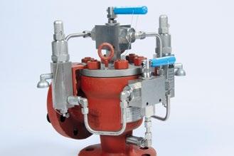
The dual pilot arrangement permits switching from an active control to a back-up control, ensuring uninterrupted pressure relief protection. The original, active control can be removed from the main valve for checking or maintenance purposes.
The spare pilot can be in place during operation or be installed just prior to switch over. When the pilot controls are subjected to corrosive service that can require more frequent maintenance cycles, this option maximizes in-service time of the PORV and increases the integrity level of the valve. Select Option #2 from page 5.
All pilot controls are manufactured with an internal filter that reduces particles in the process stream, as these particles can impede the operation of the pilot valve. For services where particulates are present in the process media, additional filtration may be required. Auxiliary filters for the pilot valve sensing line are available to complement the internal filter. This filter is mounted upstream to the pilot’s internal filter, reducing the amount of particles that can enter the pilot. As our pilot valves are non-flowing, the life cycle of the filter is dependent on the valve size, particle size and the valve usage. Select Option #3 from page 5.
One of the causes of excessive chatter in a PRV is significant pressure losses on the inlet side during a relief episode. Recommended practice is to limit the non-recoverable (friction) losses to less than 3% of set pressure. When this cannot be accomplished with piping design changes, a pilot operated relief valve equipped with a remote sense line can mitigate this issue. This arrangement allows connecting the pilot sensing line at a location close to the equipment being protected, yet not affected by the inlet pipe pressure drop, thereby avoiding chatter, damage and unstable relieving flow. Select Option R from page 5.
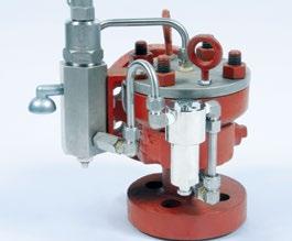
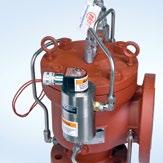
Pilot operated relief valves potentially need an option to manually or remotely depressurize before the normal overpressure settings have been reached. In addition, this option allows for testing the main valve function without cycling the pilot control. It also allows for the pilot valve, in conjunction with other valves, to provide emergency reduction of system pressure due to potential safety situations. The main valve can be cycled to the open position by venting the pressure in the dome above the piston. A manual valve option will mount directly on the main valve, which allows for manual depressurizing of the dome. Alternately, a solenoid valve will cycle the main valve remotely. Neither the manual nor remote blowdown system will interfere with the normal overpressure protection provided by the main valve and pilot. Select Option #4 or #8 from page 5.
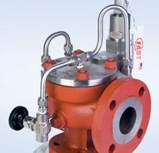
With the addition of a field test connection, the set pressure of Farris pilot operated relief valves can be verified without interrupting system protection and does not require overpressure of the system.
An auxiliary source of pressure, such as a nitrogen bottle, is connected to the pilot sensing line through a stop valve. Increasing pressure is applied through the field test connection to the pilot control, simulating the increase in system pressure. A check valve restricts the source pressure from back flowing into the main valve inlet. When the applied pressure reaches set point, the pilot control reacts as if it were sensing overpressure via the main valve sensing line. When this occurs, the auxiliary pressure reading can be compared to the nameplate value to verify set pressure. For snap acting valves, both the pilot and main valves will cycle at set pressure. For modulating valves, the modulating controls will crack slightly depending on current system pressure, the main valve may briefly cycle. To more accurately establish the modulating pilot relief valve’s set pressure, a field test connection with indicator is recommended.
The field test connection with indicator provides positive verification that set pressure has been reached. The set pressure for the current modulating relief valves is defined as the point when dome pressure is reduced to 70% of set pressure. The field test indicator is activated when the applied pressure reaches the valve’s set point and at this time, can be compared to nameplate value. Select Option #5 or F from page 5.
Reverse flow in a pilot relief valve can occur in systems where back pressure exceeds system pressure or where a vacuum can form at the inlet. In both cases a reverse differential pressure exists and it is possible for the main valve to open and allow flow from the discharge system to enter the inlet side.
A reverse flow preventer assures that the correct pressure differential is maintained and the main valve remains closed. A reverse flow preventer introduces outlet pressure into the dome of the main valve, keeping the piston firmly seated onto the nozzle, overcoming the effect of a reverse differential. This option also prevents reverse flow through the pilot control via the pilot sense line into the upstream side of the system. Select Option #6 from page 5.
Rapid pressure spikes often occur in systems with positive displacement pumps or compressors. When these pressure spikes approach or exceed the set pressure of the valve, the pilot control may actuate and cause a valve to open prematurely. A pressure spike snubber installed in the pilot valve sensing line will eliminate the negative effects of pressure pulsation. It assures that the pilot valve is sensing and reacting to mean pressure and not to instantaneous pressure spikes. Select Option #7 from page 5.
In order for a pilot operated relief valve to open, the system pressure retained in the main valve dome needs to be released. This small volume of process fluid in the dome is typically released to the atmosphere via the pilot control discharge port. This is true whether it is a snap-acting or a modulating pilot control.
Normally, the end user can accept this small amount of product loss and fugitive emissions when the process fluid is gaseous. However, if the process fluid is a liquid, flammable, or possibly hazardous, then the release to atmosphere may need to be minimized and/or eliminated.
The conventional solution is to pipe the discharge of the pilot control to a safe location or atmospheric collection system. This is not always possible or practical. In these cases, piping the modulating pilot control discharge directly to the main valve outlet is the solution. The design of the modulating pilot control features a balanced relief chamber that neutralizes the effects of back pressure to set pressure similar to that of a bellows-style spring loaded valve. Therefore the discharge for a modulating pilot control can be piped directly to the main valve outlet and is recommended for liquid applications.
This option is only available with the modulating pilot control and must be specified at the time of order. Select Option V from page 5.
A valve lift indicator allows the operator to know when the pilot operated relief valve has opened. This auxiliary option consists of a differential pressure switch as the indicator. The switch is mounted to the dome of the main valve. When the dome pressure is reduced sufficiently so that the main valve opens, the switch is actuated, allowing a signal to be sent to a remote location. In order to supply this option, please be prepared to supply information regarding the electrical source, switch contact style, and switch rating, enclosure and hazard rating. This option will be designated under SP –special construction.
Accessories Reference Table1
Test Gag (1)
Dual Pilots (2)
Auxillary Filter (3)
Manual Depressurizing4 (4)
Remote Depressurizing3 (8)
Valve Lift Indicator6
(6)
(7)
General Notes:
1. Materials of construction for optional accessories will remain consistent with main and pilot valve constructions. Not all optional accessories may be available for valves specified with special trim material, based on commercial availability
2. Option with indicator is recommended for modulating pilot control applications.
3. Customer will need to provide supplemental information to specify this option.
4. The effective CV of the manual depressurizing unit should be at least 0.4 (KV = 0.35) including any associated tubing or piping
5. When liquid service is specified, this option is recommended.
6. Furnish complete details on type of signal output desired and power supply available.
Viscosity
• ASME NB Certified: Air, Steam & Water
• Sizes: 1" x 2" to 20" x 24"
• Pressure Range: 15 psig to 6000 psig
• Temperature Range: -450°F to +1500°F
• Materials*: Carbon Steel, Stainless Steel, Monel & Hastelloy C
• Options: Balanced Bellows, O-Ring Seat, Open Bonnet
• CE Approved
• ASME NB Certified: Air, Steam & Water
• Sizes: 1" x 2" to 12" x 16"
• Pressure Range: 15 psig to 6170 psig
• Temperature Range: -450°F to +500°F
• Materials*: Carbon Steel, Stainless Steel, Monel & Hastelloy C
• Actuation: Snap and Modulating Controls
• Options: Field Test Connections, Reverse Flow Preventer, Remote Depressurizing & Auxiliary Filters
• CE Approved
• ASME NB Certified: Air, Steam & Water
• Sizes: ½" x 1" to 1½" x 2½"
• Pressure Range: 15 psig to 6500 psig
• Temperature Range: -450°F to +750°F
• Materials*: Carbon Steel, Stainless Steel, Monel & Hastelloy C
• Options: Balanced Design, O-Ring Seats, Flanged, Socket Weld, Welding Nipple, & Sanitary Connections
• CE Approved
*Other materials available upon request. Please consult the factory.
• ASME NB Section I & VIII Certified: Steam & Air
• Sizes 1¼" x 1½" to 6" x 8"
• Pressure Range: 15 psig to 1000 psig
• Temperature Range: -20°F to +1000°F
• Materials: Carbon Steel, Stainless Steel, Chrome-Moly
• Options: Test Gag
• CE Approved
• ASME NB Section I & VIII Certified: Steam & Air
• Sizes: 1" x 2" to 4" x 6"
• Pressure Range: 15 psig to 1500 psig
• Temperature Range: -20°F to +1000°F
• Materials: Carbon Steel, Stainless Steel, Chrome-Moly
• Options: Closed Bonnet(6600) & Test Gag
• ASME NB Certified: Air, Steam & Water
• Sizes: ½" x 1" & ¾" x 1" (1890) ½" x ¾" & ¾" x ¾" (1896M)
• Pressure Range: 15 psig to 800 psig (1890) 15 psig to 300 psig (1896M)
• Temperature Range: -20°F to +750°F (1890) -450°F to +400°F (1896M)
• Materials: Stainless Steel Body & Trim (1890) Brass Body & Trim, Bronze Bonnet (1896M)


NV V
Farris Engineering, a business unit of Curtiss-Wright Headquarters: 10195 Brecksville Road, Brecksville, OH 44141 USA • Telephone: 440-838-7690 • Fax: 440-838-7699 • www. cw-valvegroup.com/farris
Facilities: Brecksville, OH, USA; Brantford, Ontario and Edmonton, Alberta, CA; Corby, Northants, UK; São Carlos-SP, Brazil; Tianjin, Beijing, China; Delhi, India Offices Worldwide: For a listing of our global sales network, visit our website at www.cw-valvegroup.com/farrisdistributors.
While this information is presented in good faith and believed to be accurate, Farris Engineering, division of Curtiss-Wright Flow Control Corporation, does not guarantee satisfactory results from reliance on such information. Nothing contained herein is to be construed as a warranty or guarantee, expressed or implied, regarding the performance, merchantability, fitness or any other matter with respect to the products, nor as a recommendation to use any product or process in conflict with any patent. Farris Engineering, division of Curtiss-Wright Flow Control Corporation, reserves the right, without notice, to alter or improve the designs or specifications of the products described herein.


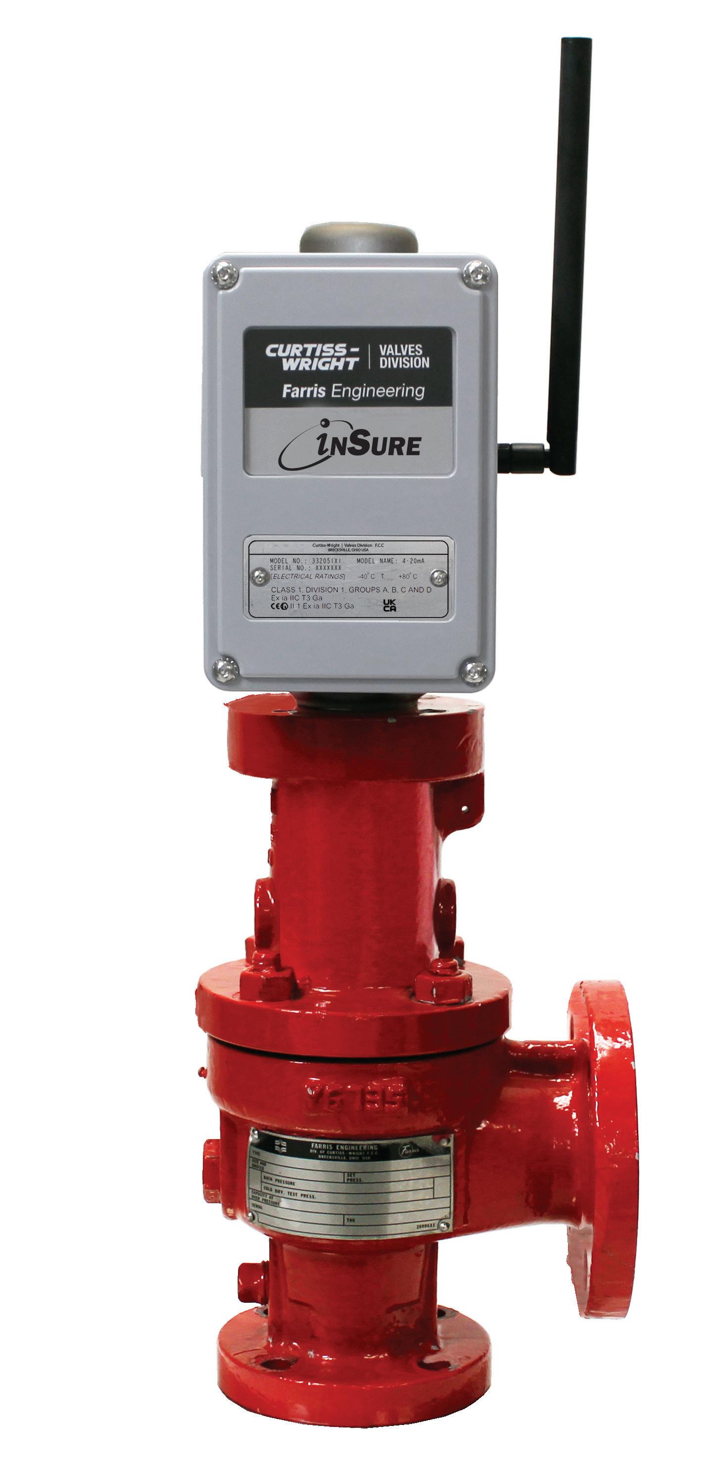
This Device provides real time monitoring for pressure relief valves. It communicates with your DCS, Distributed Control System, or through the app providing valve status, access to reporting and notification of pressure events.
•Provides communication options for mobile field & control systems
• No penetration of valve’s pressure boundary
•Stores data for discharge analysis
•Calculate flow based on valve lift
•Retrofit inSure to existing Farris Engineering 2600 Series valve
•Live Valve Data
•Network Info
•Valve Records Retention

Data also can be accessed using the inSure app via Bluetooth, iOS and Android.


2680 New Butler Rd. New Castle, PA 16101
Tel: 724-368-8725
Email: sales@portersvilleprd.com
RICHMOND
700 Southlake Blvd. North Chesterfield VA 23236
Tel: 804-593-2384
Email: sales@portersvilleprd.com
www.portersvilleprd.com
143 S.Thomas Rd. Tallmadge, OH 44278
Tel: 330-253-4800
Email: sales@portersvilleprd.com
1551 Shipley Ferry Road
Blountville, TN 37617
Tel: 423.482.0496
Email: sales@portersvilleprd.com
TALLMADGE
133 S.Thomas Rd. Tallmadge, OH 44278
Tel: 833-556-2600
Email: inventory@prddistribution.com
www.prddistribution.com
1500 E. Burnett St. Signal Hill, CA 90755
Tel: 562-424-8108
Email: Sales@BV-BM.comcom


403 Technology Dr South Point, OH 45680
Tel: 740-377-0012
Email: sales@portersvilleprd.com
3800 Fruitvale Avenue Bakersfield, 93308
Tel: 661-589-6801
Email: Sales@BV-BM.com
3195 Park Road, Benicia, CA 94510
Tel: 707-590-6688
Email: Sales@BV-BM.com