TECHNOLOGY & ENVIRONMENT 3
ARDE100022023-4SS1SEM1 December 2023
S2021503 S2082971

ARDE100022023-4SS1SEM1 December 2023
S2021503 S2082971
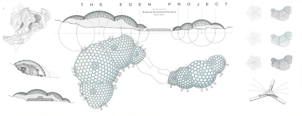
NICHOLAS GRIMSHAW
Project Details:
Architect: Nicholas Grimshaw
Completion date: 1998 2001 Cost: £141 Million
Location: St Austell, Cornwall
Complete width of largest structure: 110m wide, 55m high and 240m long Structural Type: Hex-Tri-Hex Space Frame
Project Information
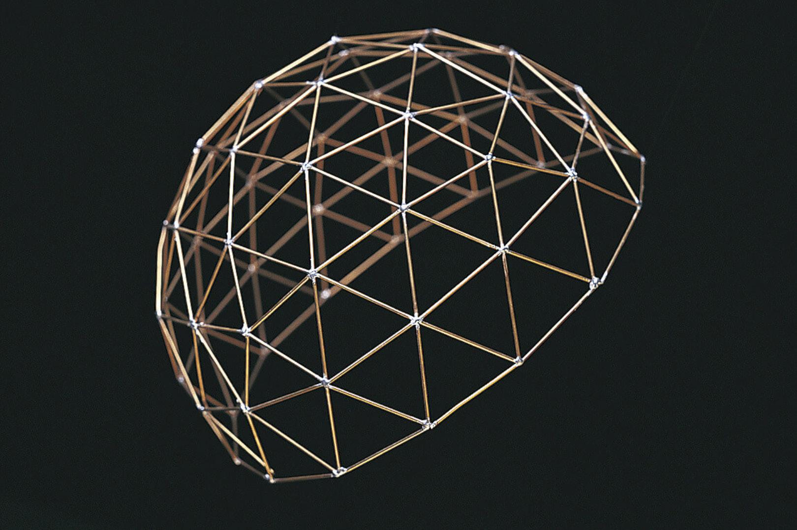
The architectural configuration employed in each dome of the Eden Project is characterized by a hex-tri-hex space frame featuring a dual layered structure. The outermost layer is predominantly comprised of hexagonal forms interspaced with the occasional pentagonal component, the largest of which spans approximately 11 meters in diameter (80m2). In contrast the inner layer is constructed by affixing hexagons and triangles in a close integrated fashion, utilizing mechanical fastening methods. The total mass of the structural steelwork in these domes is marginally larger than the mass of the atmospheric air encapsulated within the biomes.
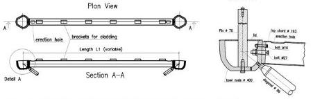
The Arches
Alongside the intersection of the domes a triangular truss system is in place, spanning up to 100m. The top and bottom chord beams are bent to create the curve. For construction the girders were manufactured in three segments off-site and the rest were welded onsite. The arches rest on a hinge supported concrete base
The main design parameters:
- Rigid connection for three tubes, hinged connection for three tubes
- Minimum tolerances
- No side welding
- Architecturally pleasing
The node is an enhancement of the node used when circular or hollow tubes are joined by bolts. Constructed from cast iron and a weight of approximately 80kg, each cut and drilled by a computer aided manufacturing process limiting the tolerance to a minimum.
All top chord tubes have diameter of 193mm to match the same connection as the node but differing wall thicknesses to suit the effected forces and buckling lengths. As the geometric angles are hosted by the node the ends of the top chord are rectangular for ease in manufacturing.
The spaceframe was assembled within a vast birdcage scaffold, from a kit of individual parts. Primary elements hot dip galvanized prior to arrival at site, nodes were finished off site with a zinc paint system. The elements were held and lifted into position by a series of mobile cranes on piled foundations.
Project Details:
Architect: Zaha Hadid
Completion date: 2019 – 2023
Cost: £141 Million
Location: Jiangxi River, Chengdu, China
Complete width of largest structure: 55m wide, 30m high and 295m long
Structural Type: Cable Stayed Bridge
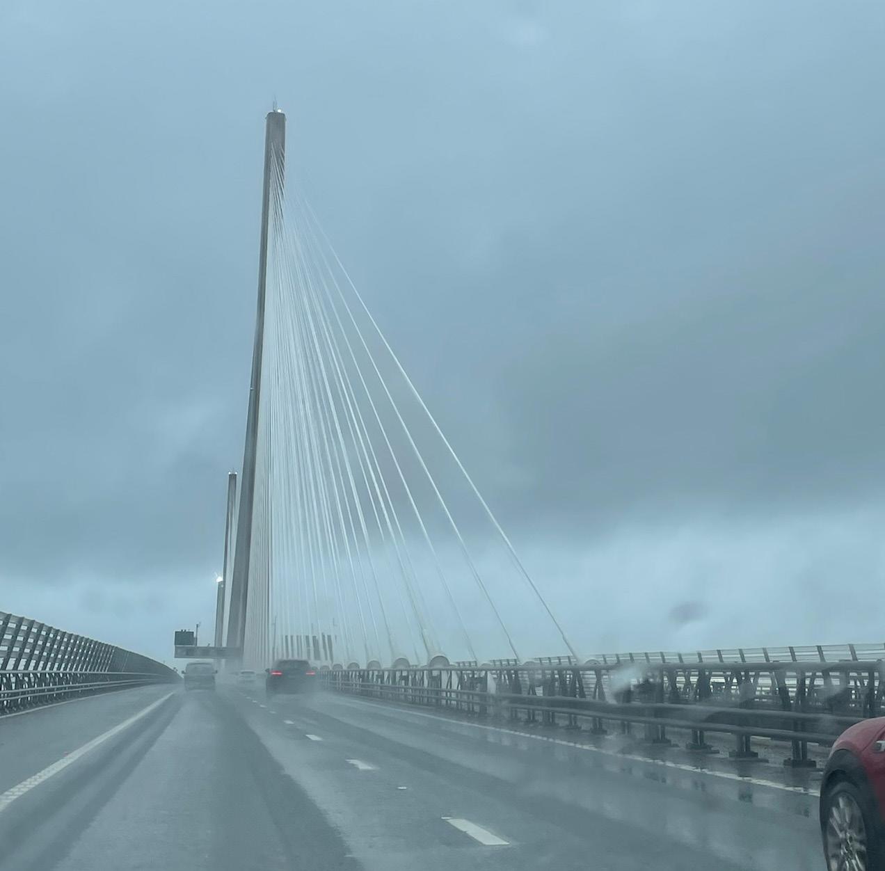
Project Information
This bridge, spanning the Jiangxi River, is an essential component of the regional transportation network, facilitating the efficient movement of goods and people. In this academic analysis, we shall delve into the structural systems of the Jiangxi River Bridge, focusing on its key components, materials, and design principles. It is characterized by a single central tower that supports a prestressed concrete deck through an array of high-strength steel cables. The bridge’s central span, often the longest, is flanked by multiple smaller spans supported by reinforced concrete piers strategically positioned to distribute loads effectively. The materials employed in its construction are carefully selected to ensure structural integrity and longevity.
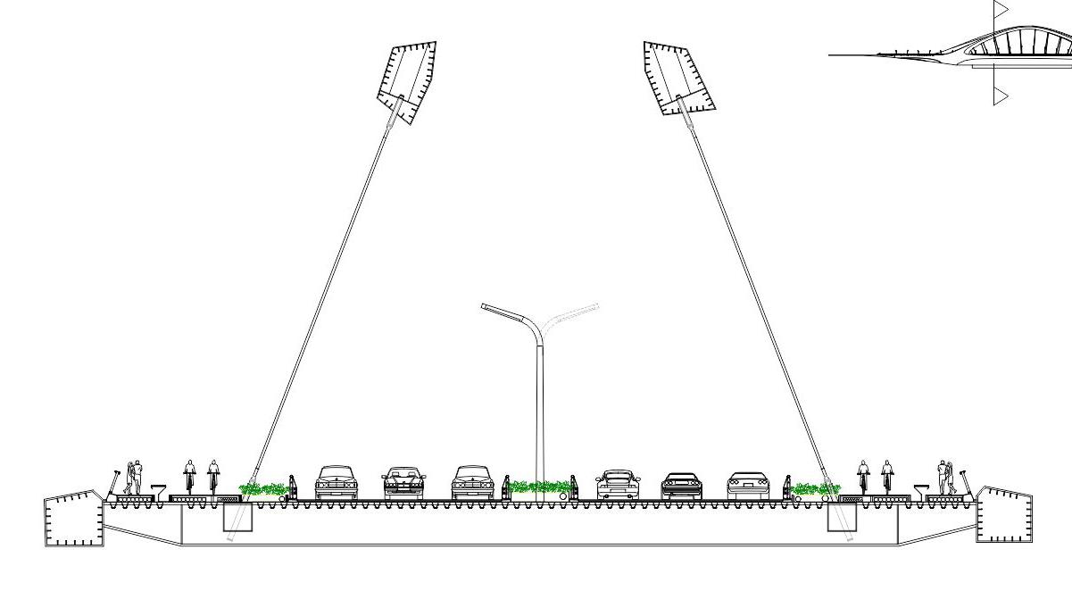
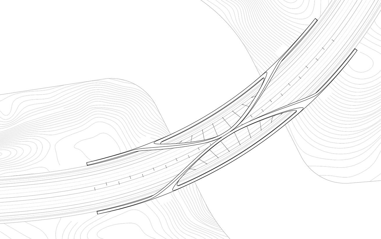
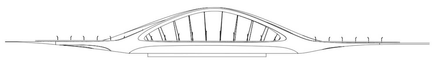
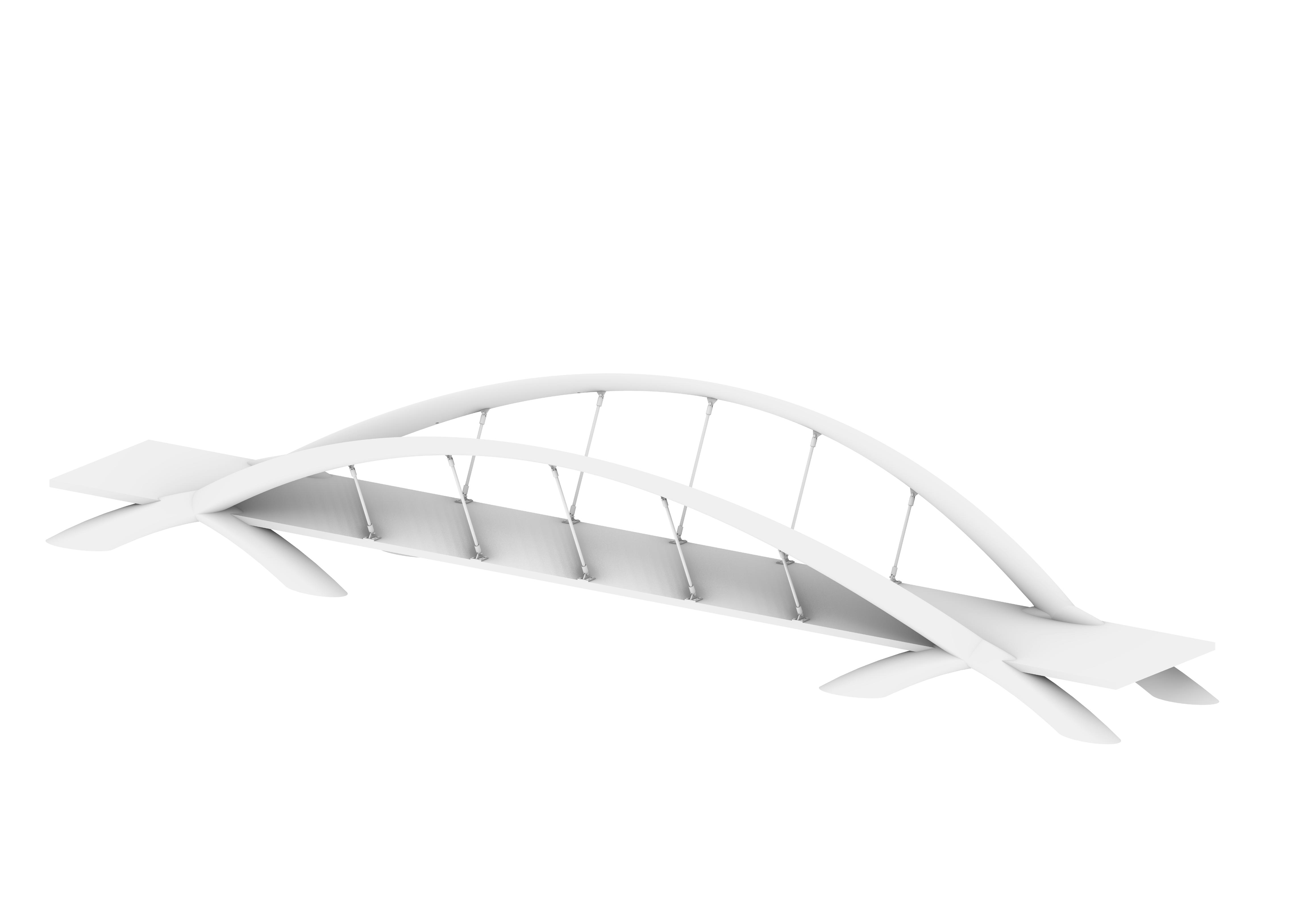
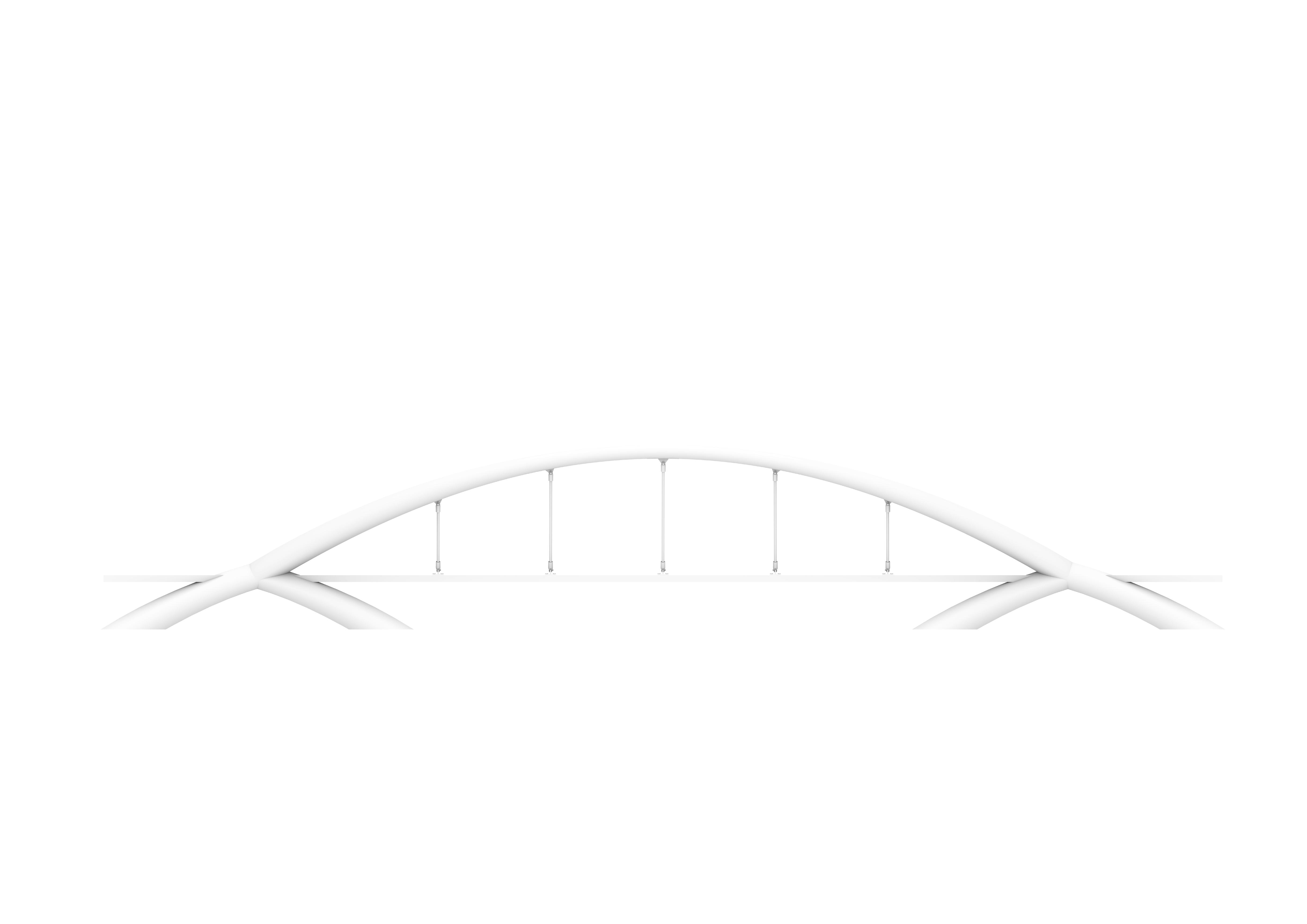
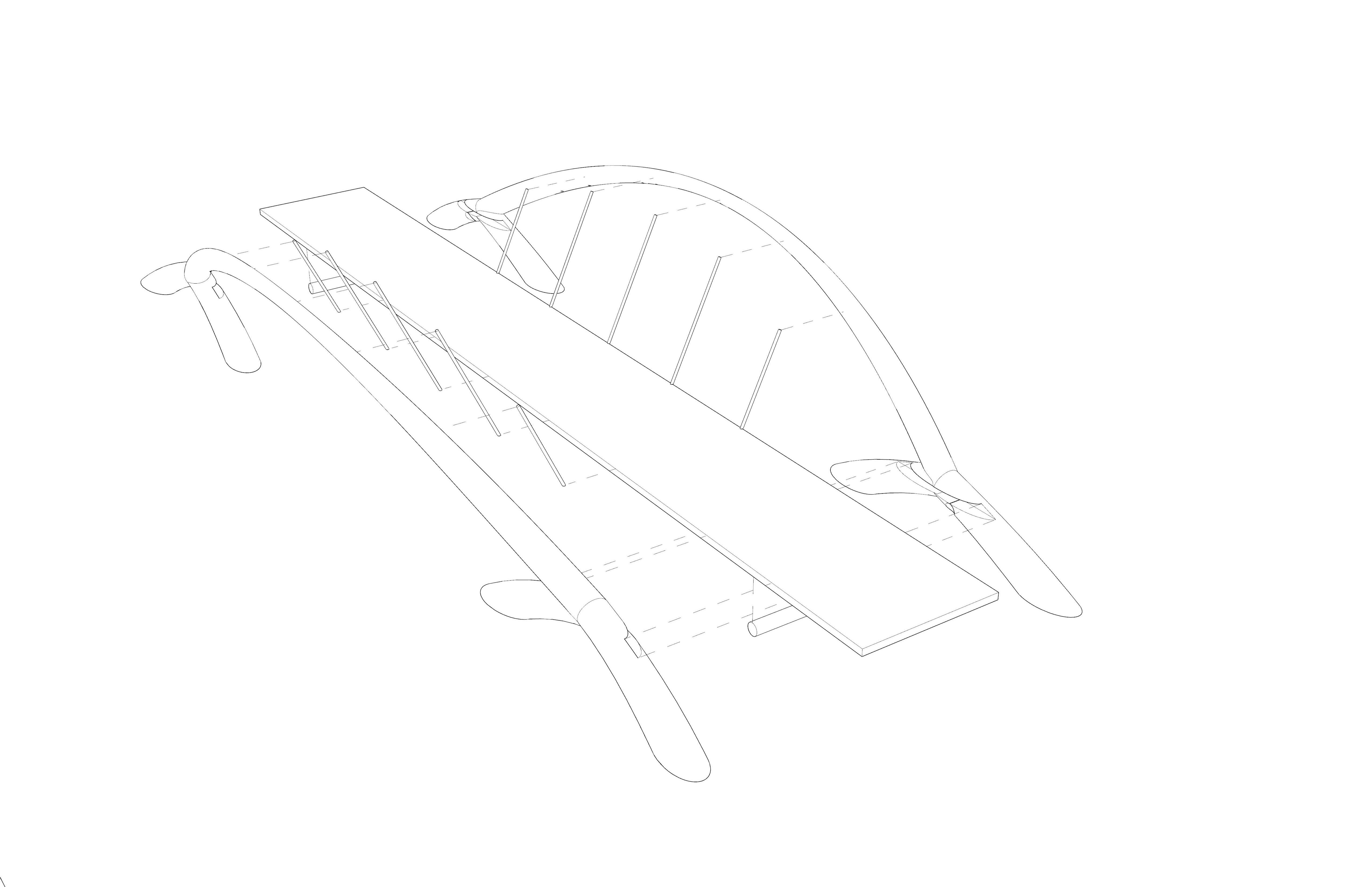
Provide the most efficient bridge structure for spans between 120-250 meters. Composed of two primary steel arches (30 meter rise), that touch at the crown to stabilize the structure from lateral winds. Arch height to span ratio: 1:6. Arches connect to base by longitudinal box girders alone the edge of the road deck – these ties resist outward horizontal thrust of each arch, reducing horizontal loads. Dynamic curvature of the supporting piers and abutments taper into the primary arches and deck, to define a sculptural landmark. Abutments incorporate connectors which link the road deck to the west line roads surface. Intermediate piers are located beneath the springing points of the arch on each riverbank.
Construction of materials / assembly:
Abutments constructed using conventional in-situ reinforced concrete techniques.
Steel box sections of each arch, prefabricated in optimal dimensions for transportation and assembly on site. Edge box girder sections within the road deck include cable anchorages, prefabricated and delivered in sections to be spliced together with on-site welding. Prefabricated plate cross girders were delivered to the site and connected to edge girders by a bolted cover plate splice connection. Concrete road deck has been constructed from precast panels fixed to the cross girders by in-situ concrete stitch pours. Mobiles cranes lifted all prefabricated steelwork and precast concrete elements within the bridge’s short assembly schedule.
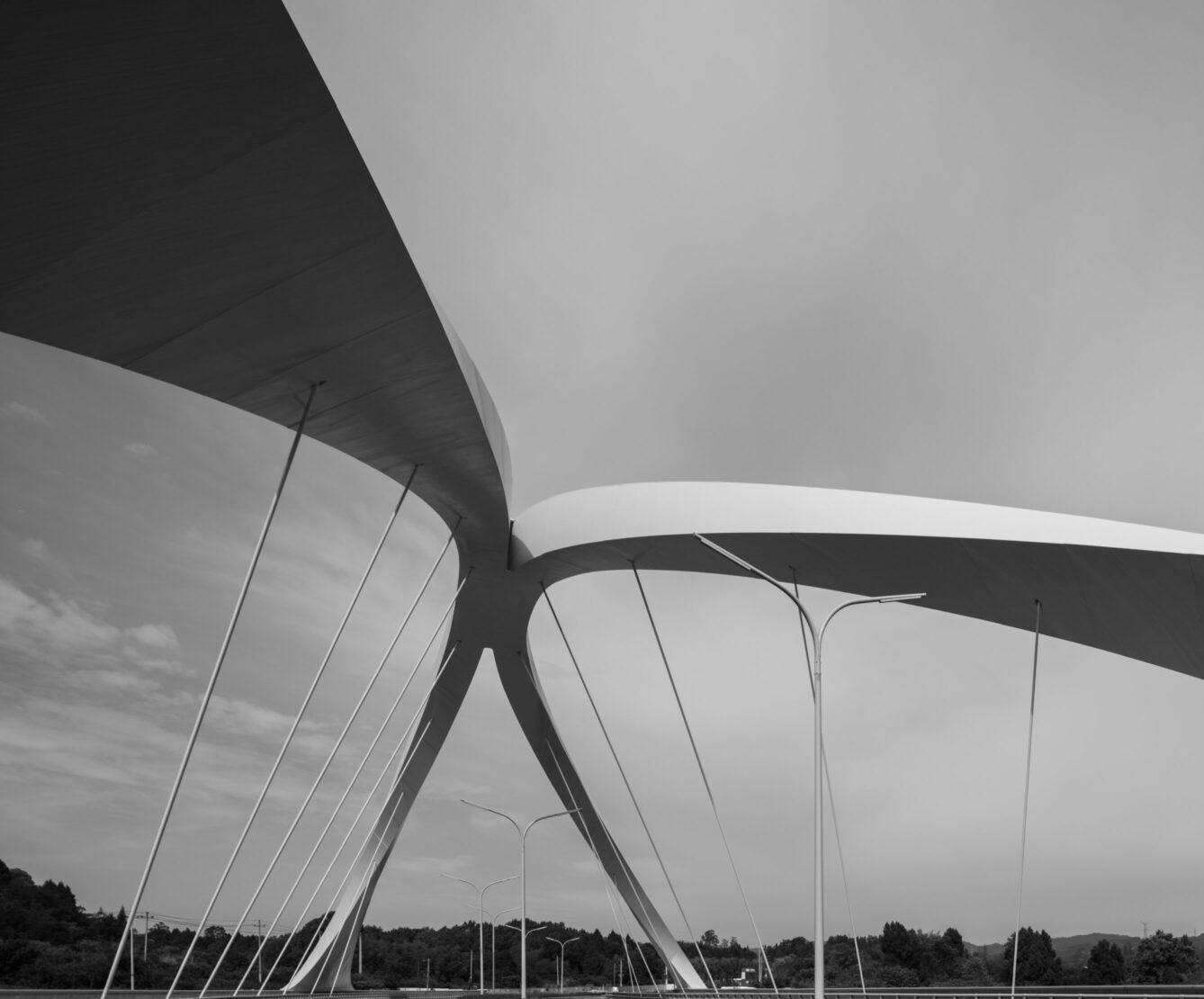
Photograph and drawings recieved from Zaha Hadid Architects
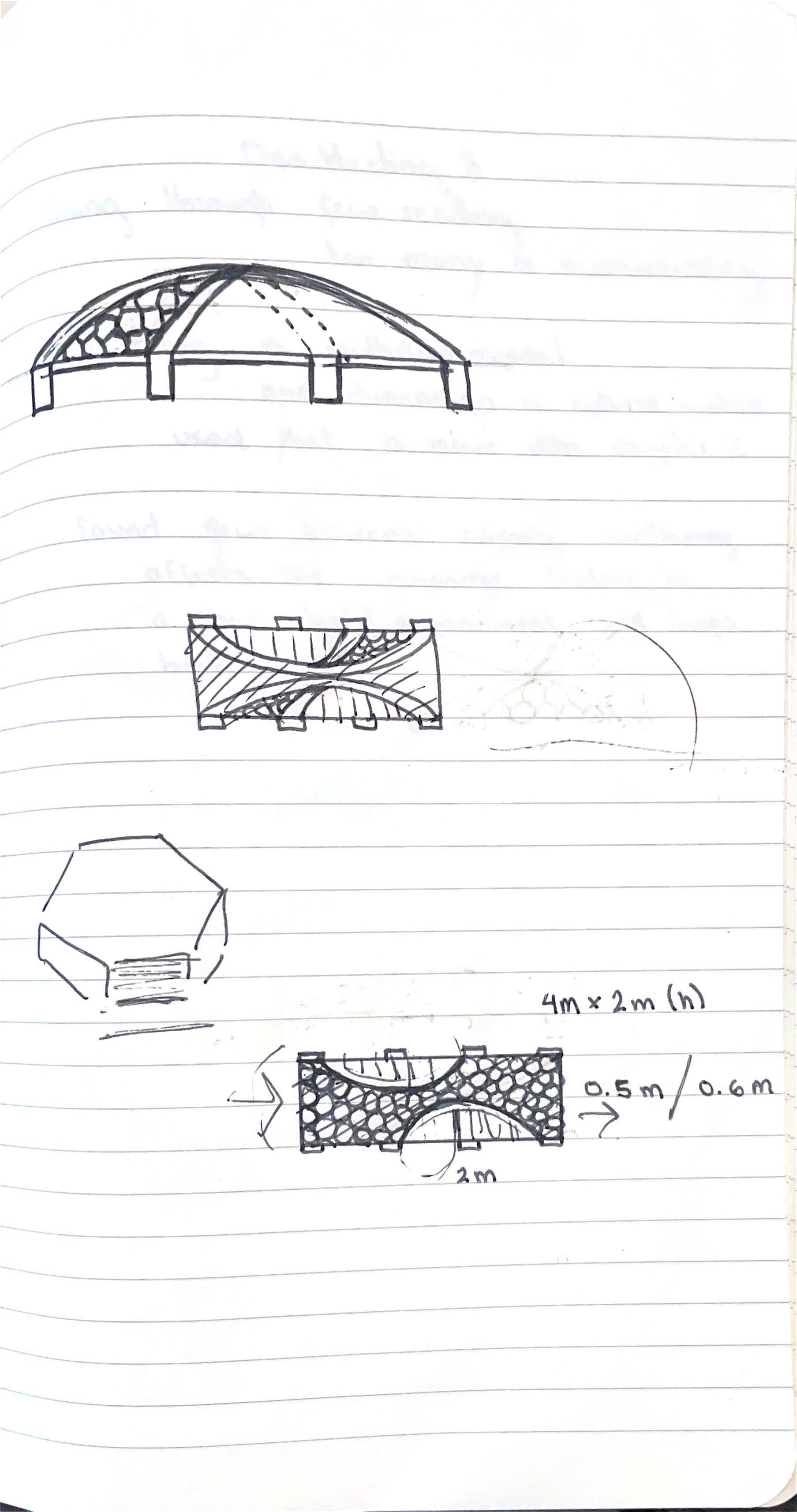
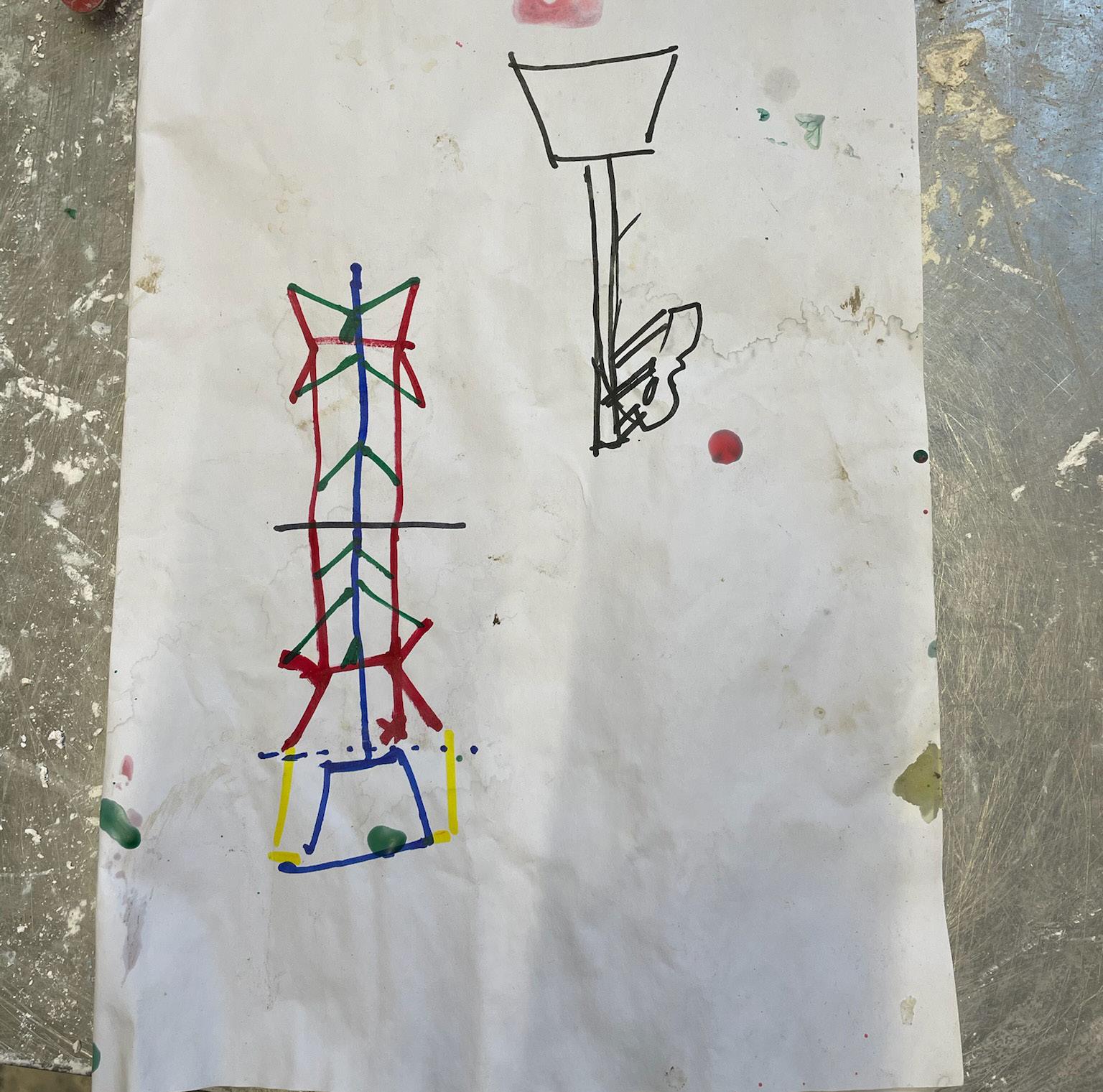
Initial design:
Original design included concaved hexagonal forms inspired by The Eden Project, fit between inward angled arches, covering the bridge with openings on either side.
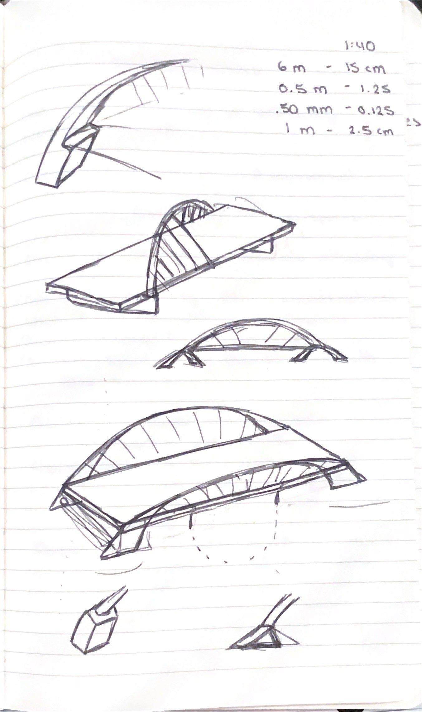
While thinking about how the design would be modeled, there was a reassesment of the design which resulted in the removal of the hexagonal forms. Following, there were various arch designs sketched and thought about thoroughly before a final form was decided on, and measurements were considered.
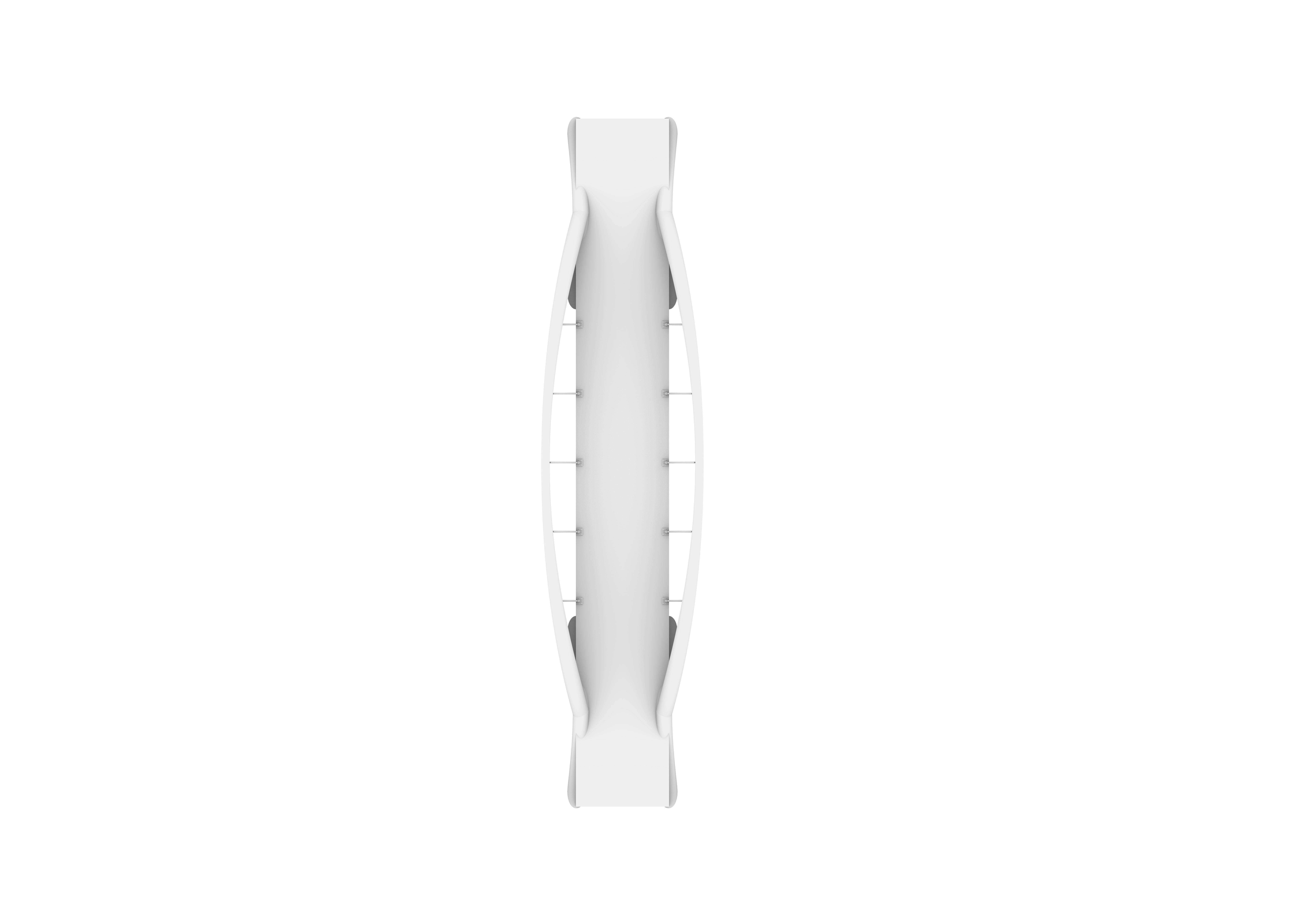


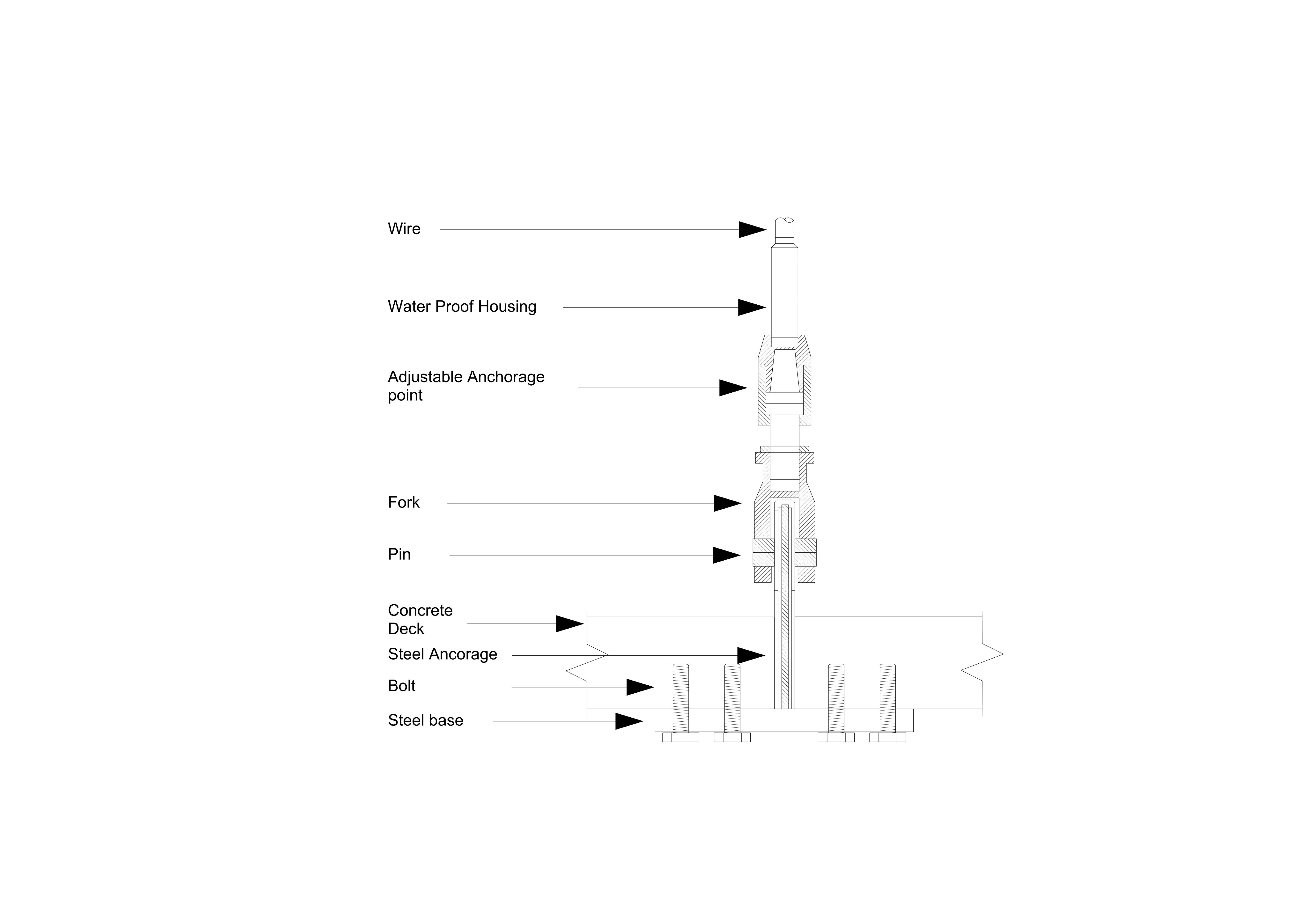
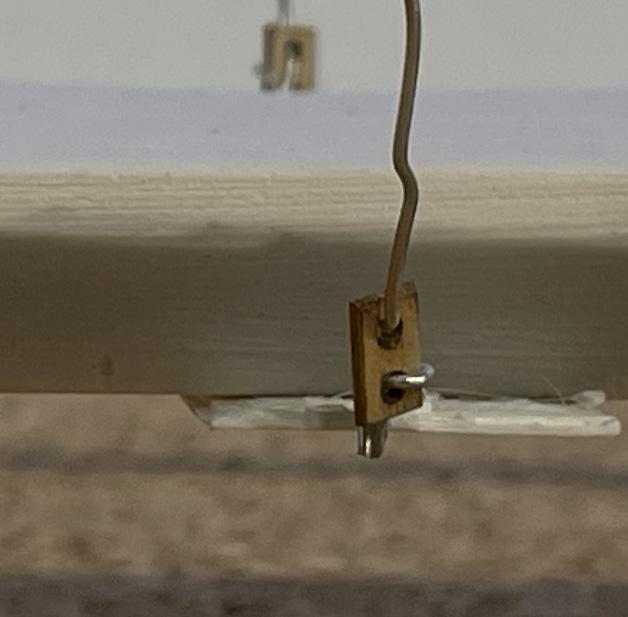
New steel plate sitting on the underside of the concrete base reducing the strain on the concrete. This is directly attached to the wire through the concrete deck.
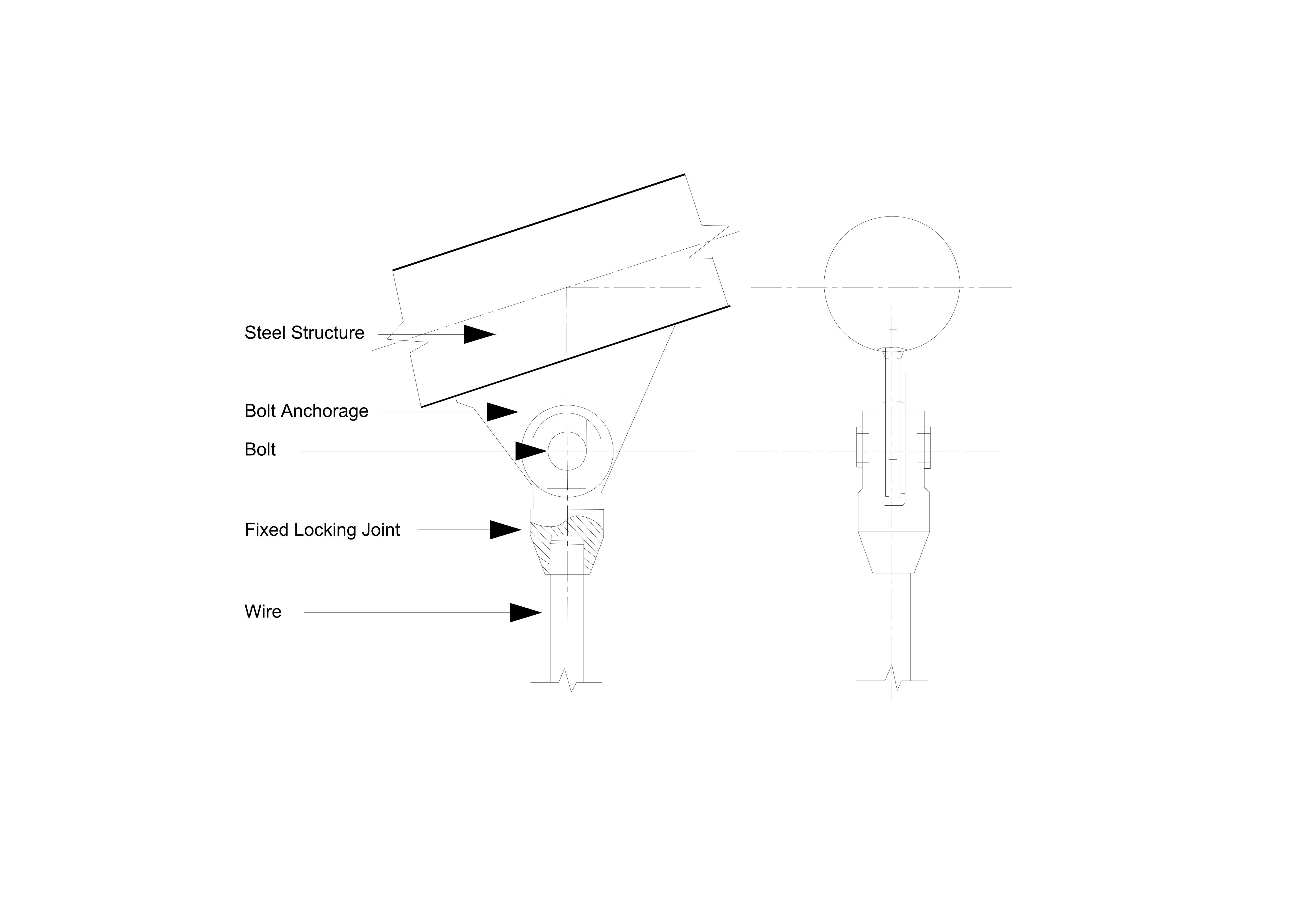
Fixed Anchorage Point
Rotating Anchorage Point
Top anchorage
Where does the design come from
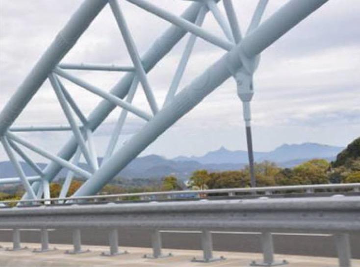
The top anchorage takes influence from the new Saikai Bridge in Japan, this bridge has significant similarities in form with two steel arches and a concrete deck hung from wire suspender cables.
Description
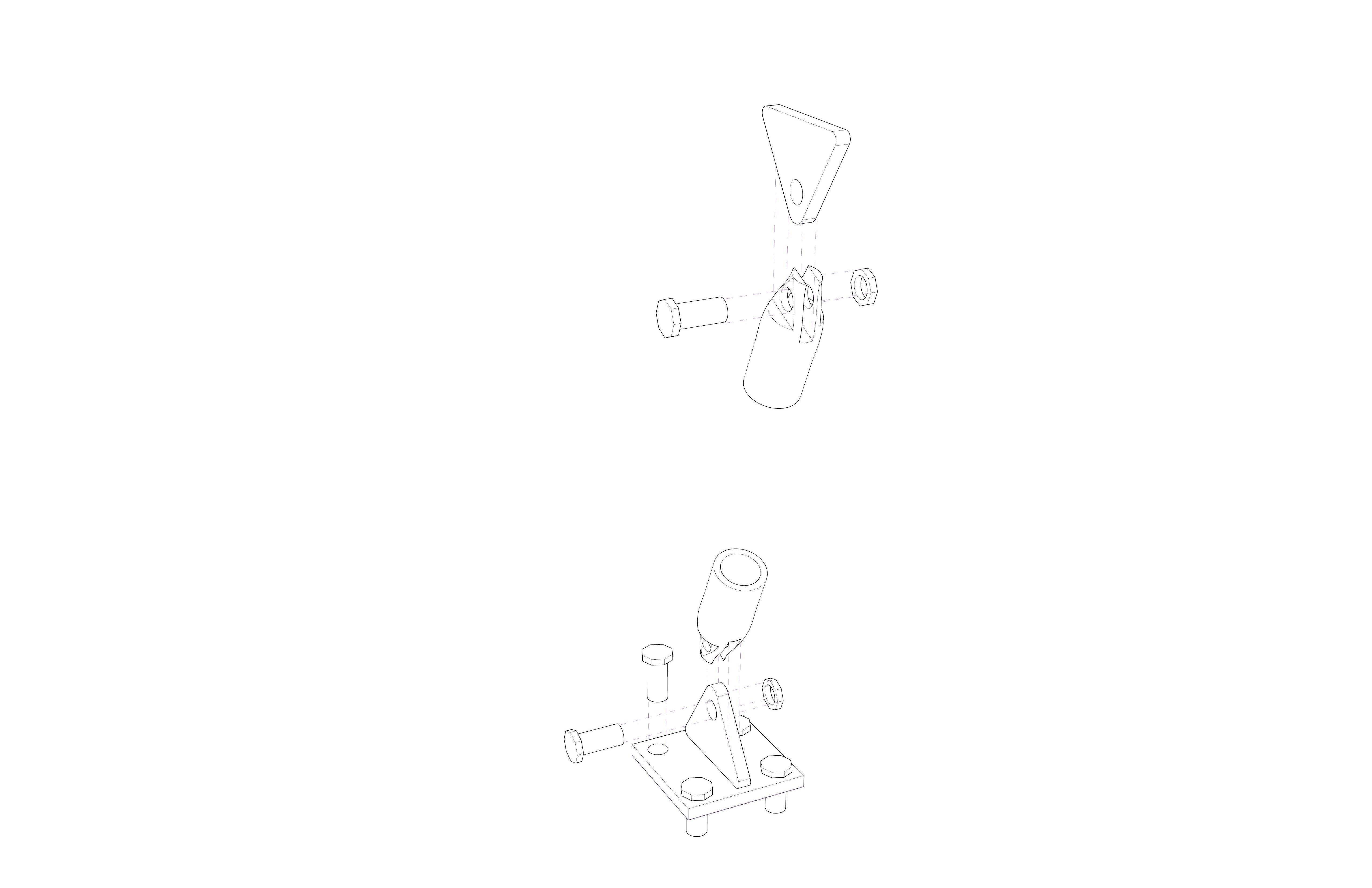
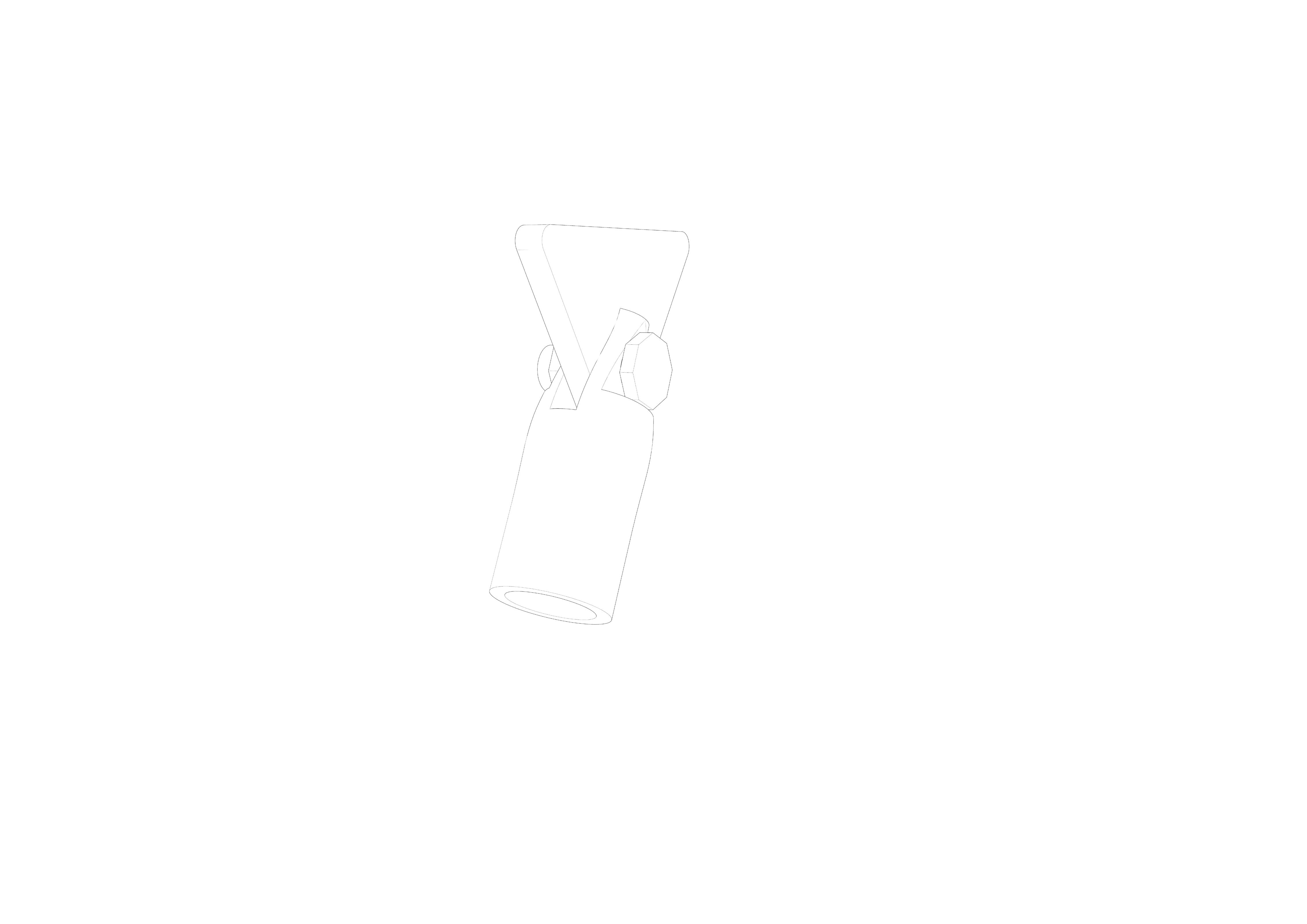
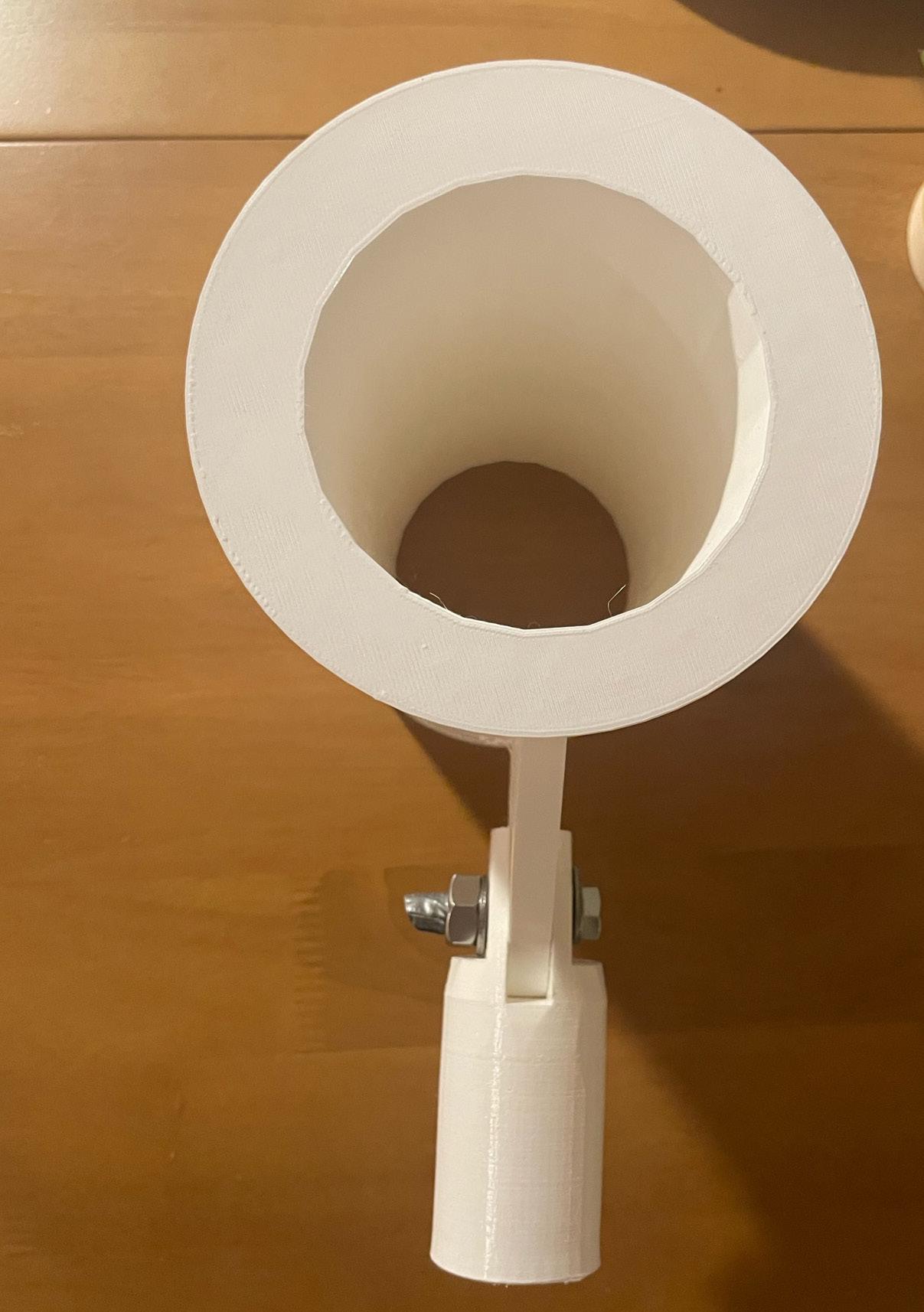
The high strength steel wire joins to the structural steel curves using a fork a bolt system. A cylindrical unit with a central segment removed (creating a fork like form) is fixed to the steel wire. A steal plate with an eyelet hole is then welded vertically to the structural steel curves. A snug-tight bolt is then fixed through the fork and plate. A sung-tight utilises the higher shear strength of high-strength bolts with the instillation procedure of a common bolt which are not fully tensioned. This joint allows for minor movements in the wire while providing a high strength connection to the steel structural system.
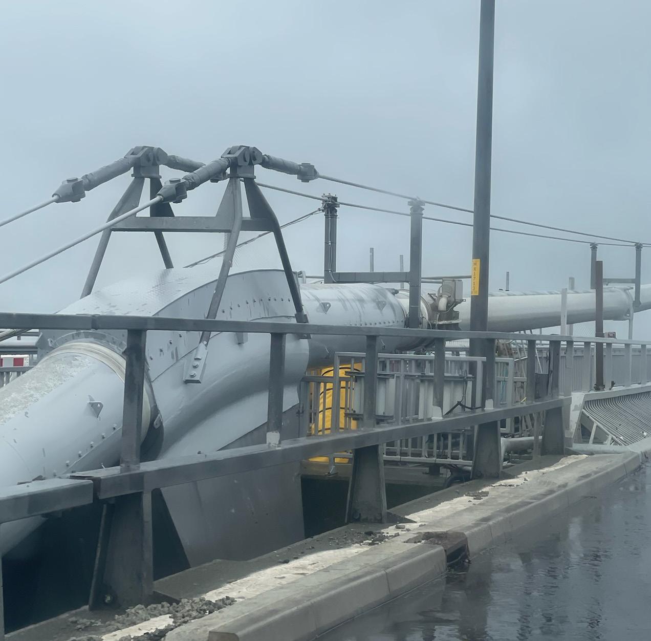
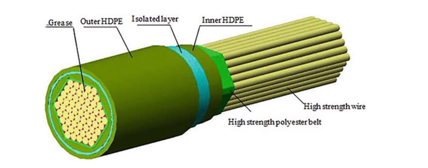
High strength suspender cables
High strength suspender cables consist of hundreds of smaller high strength wires fixed in a hexagonal form by a high strength polyester belt.
Each wire is coated with grease prior to construction to allow minor movements in the suspender cables allowing for additional tension.
To avoid damage to the wires, the polyester belt is coated with two layers of high-density polyethylene and an isolation layer in-between to reduce the likelihood of a current passed through the structure.
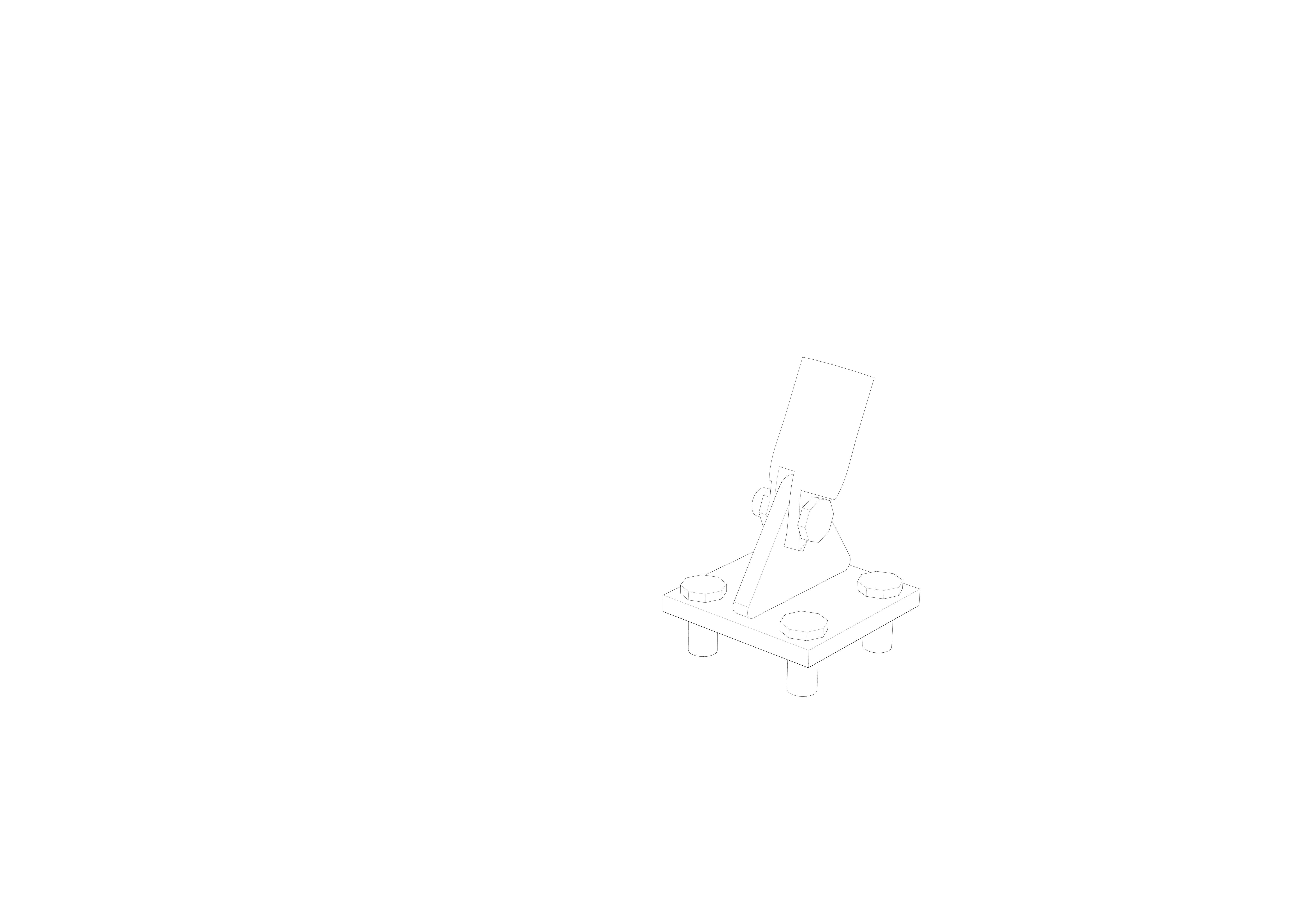
Bottom anchorage
Where does the design come from
The top anchorage takes influence from the new lupu bridge in shanghai, this bridge has significant similarities in form with two steel arches and a concrete deck hung from wire suspender cables.
Description
The high strength wire joins at an adjustable anchorage point, this provides a screw type tightening point, allowing for tension on the wire to manually adjusted throughout the construction. Similarly, to the top anchorage the cylindrical steel unit then fixes via a snug-tight bolting system to a steel plate. The steel plate attaches directly though the concrete deck to the steel longitudinal stiffening girders, located directly under the concrete deck. This process spreads the load of the deck, reducing the likelihood of failure within the concrete. The deck itself is placed directly on top of the longitudinal stiffening girders.
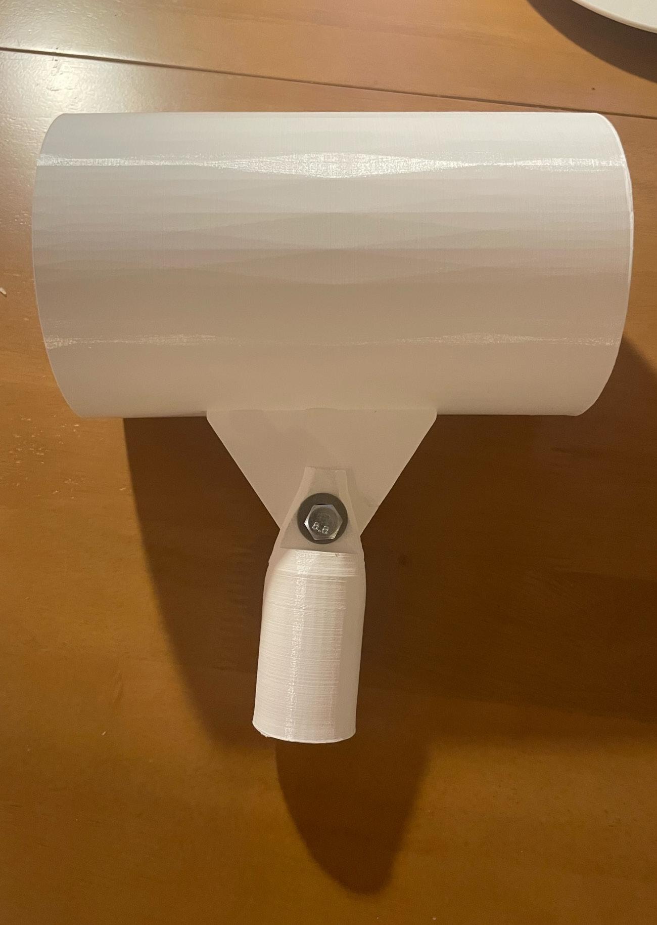
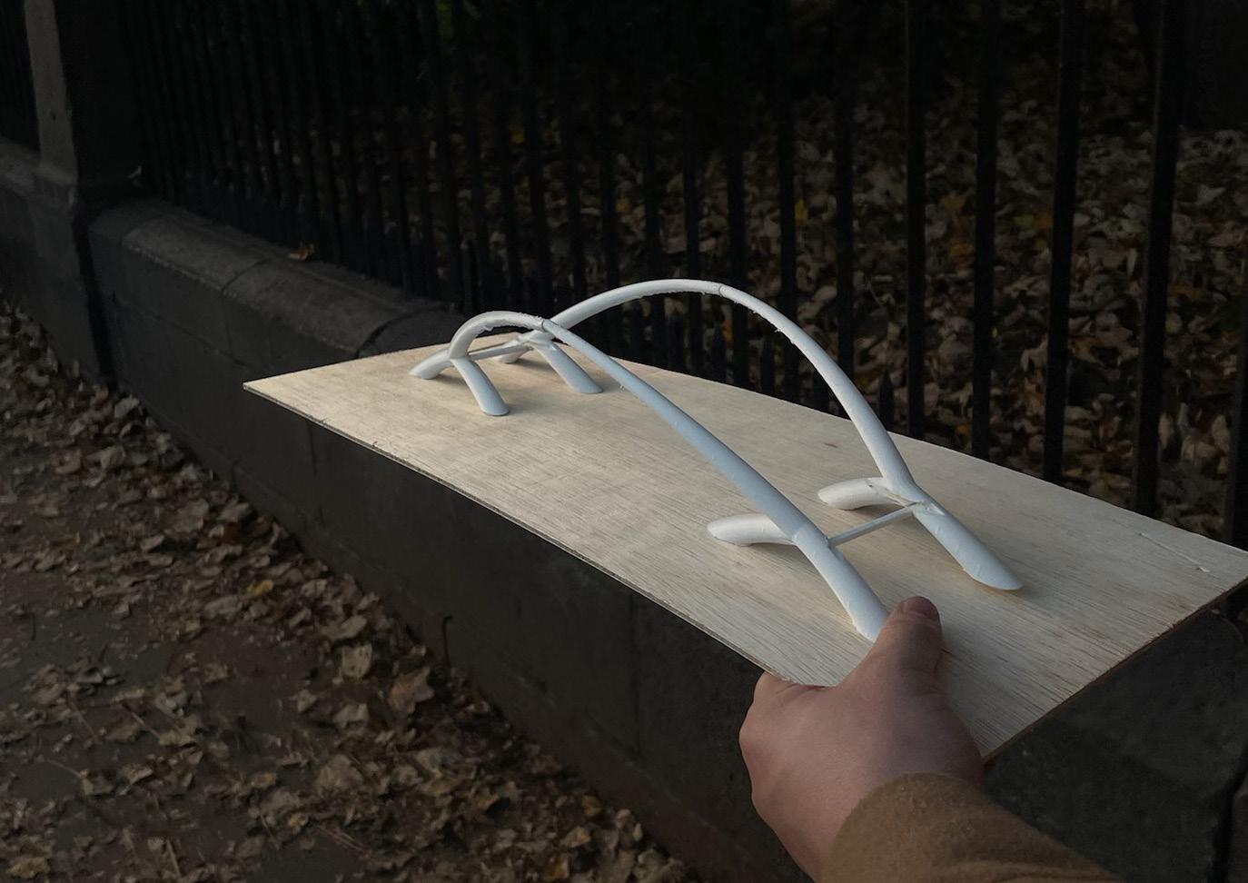
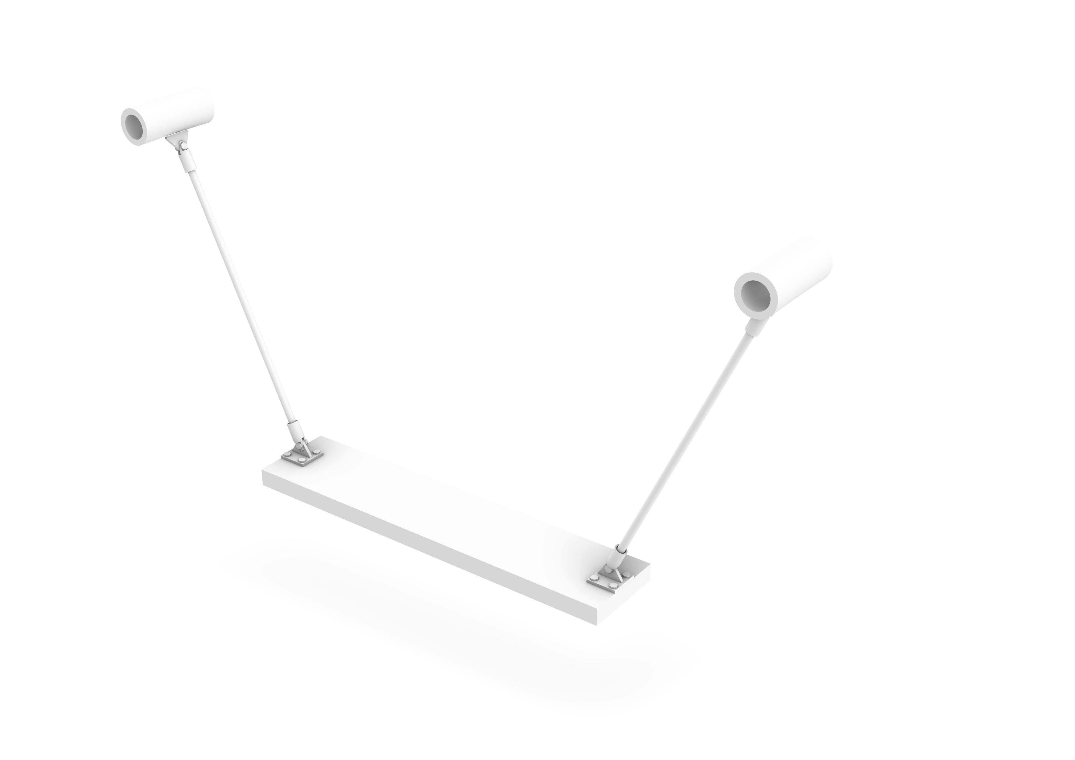
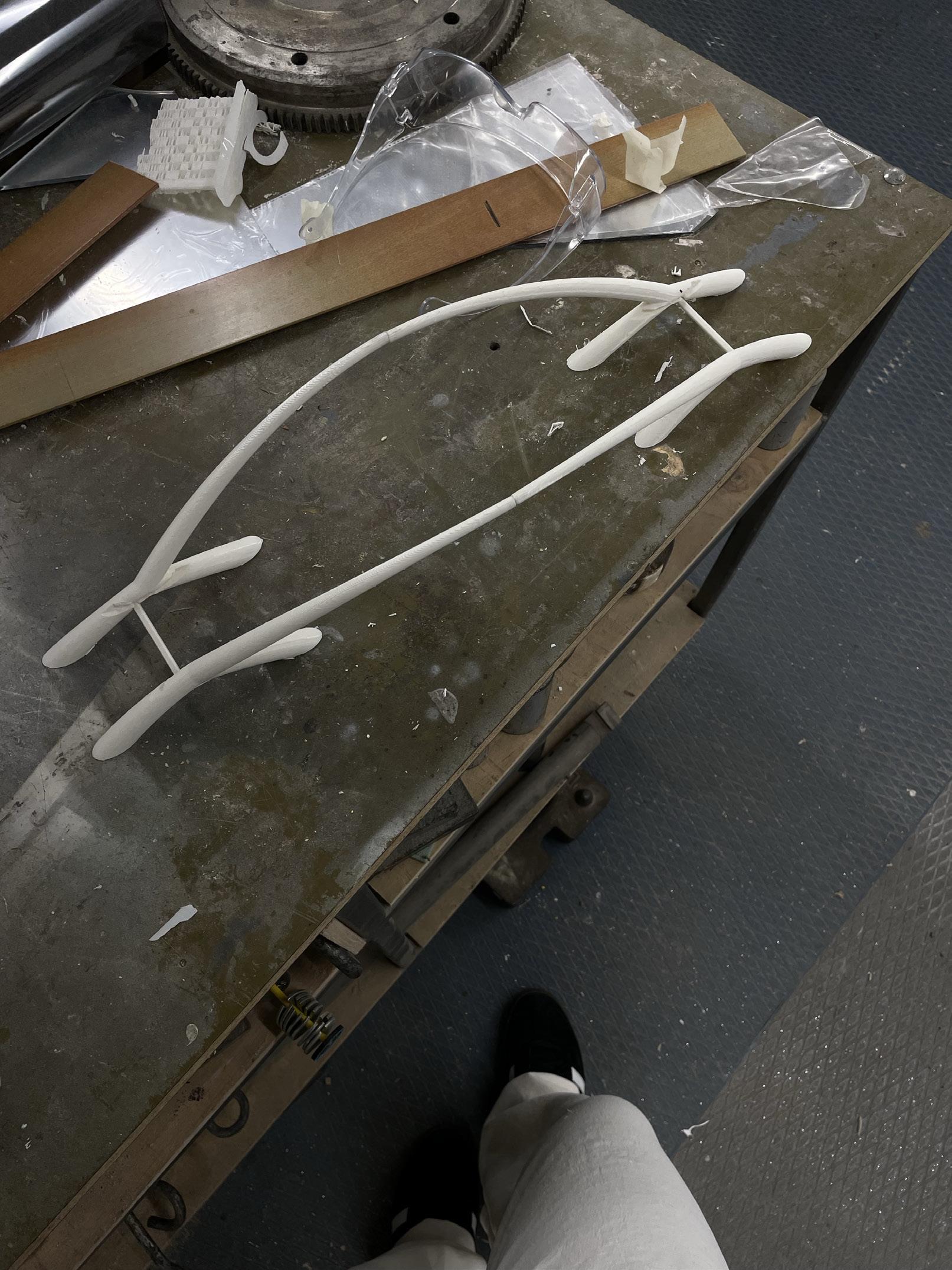
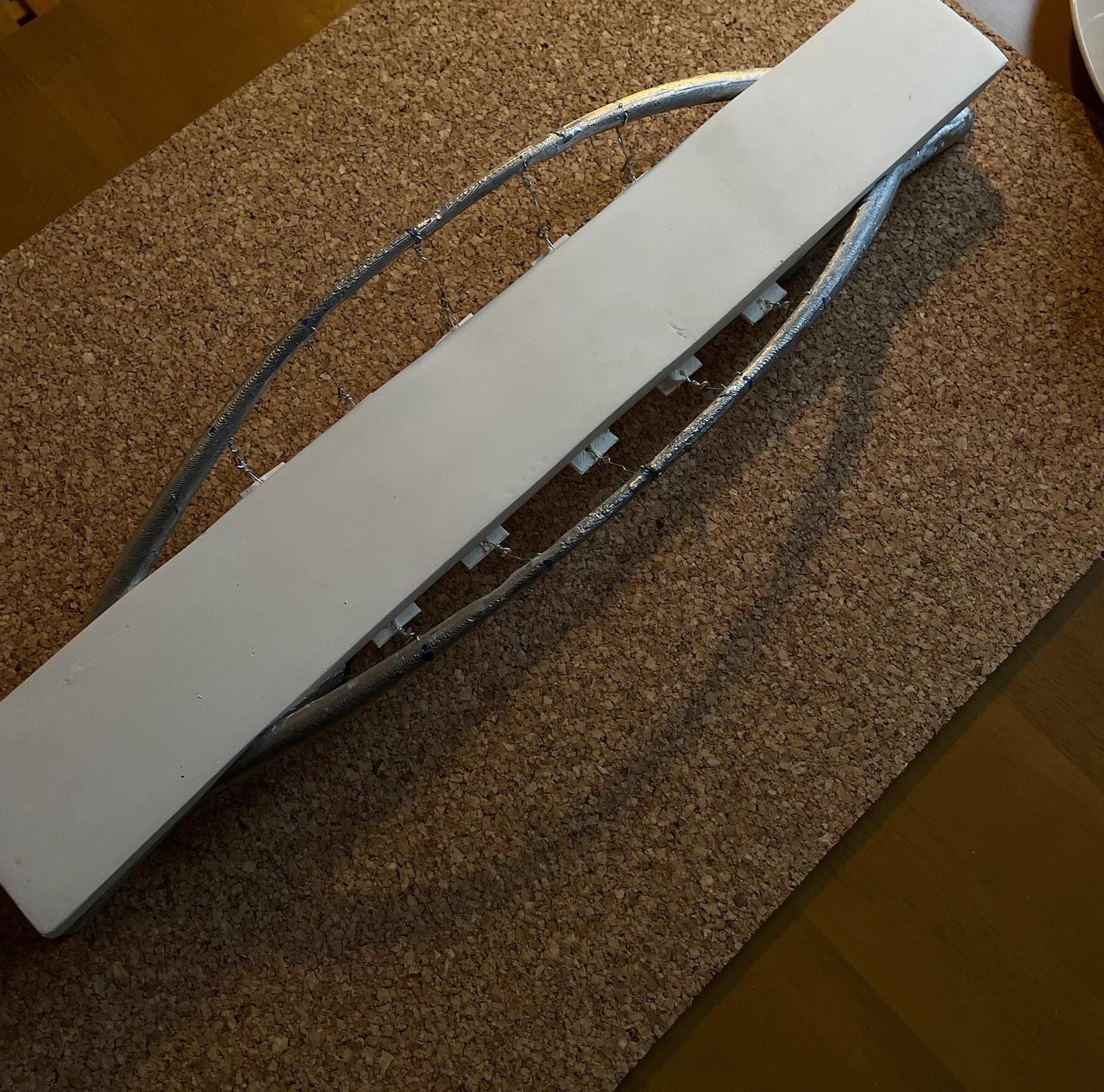
Joint model scale 1:1
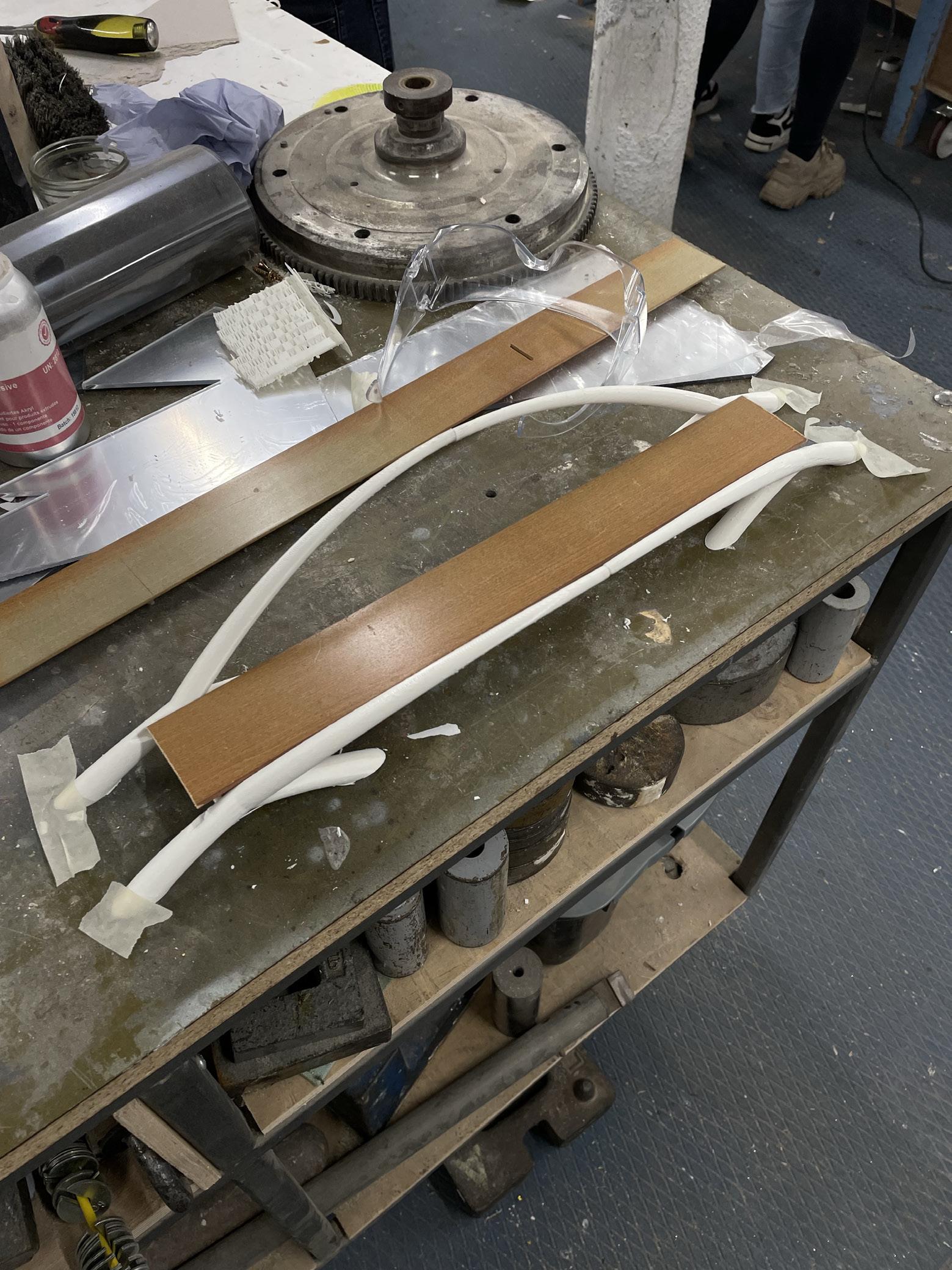
1. Utilising the 3D model produced on Rhino we fabricated a 3D printed model. This was discretised into 6 separate parts to aid the printing process and mimic a realistic construction process. This was then glued together using polycement plastic adhesive.
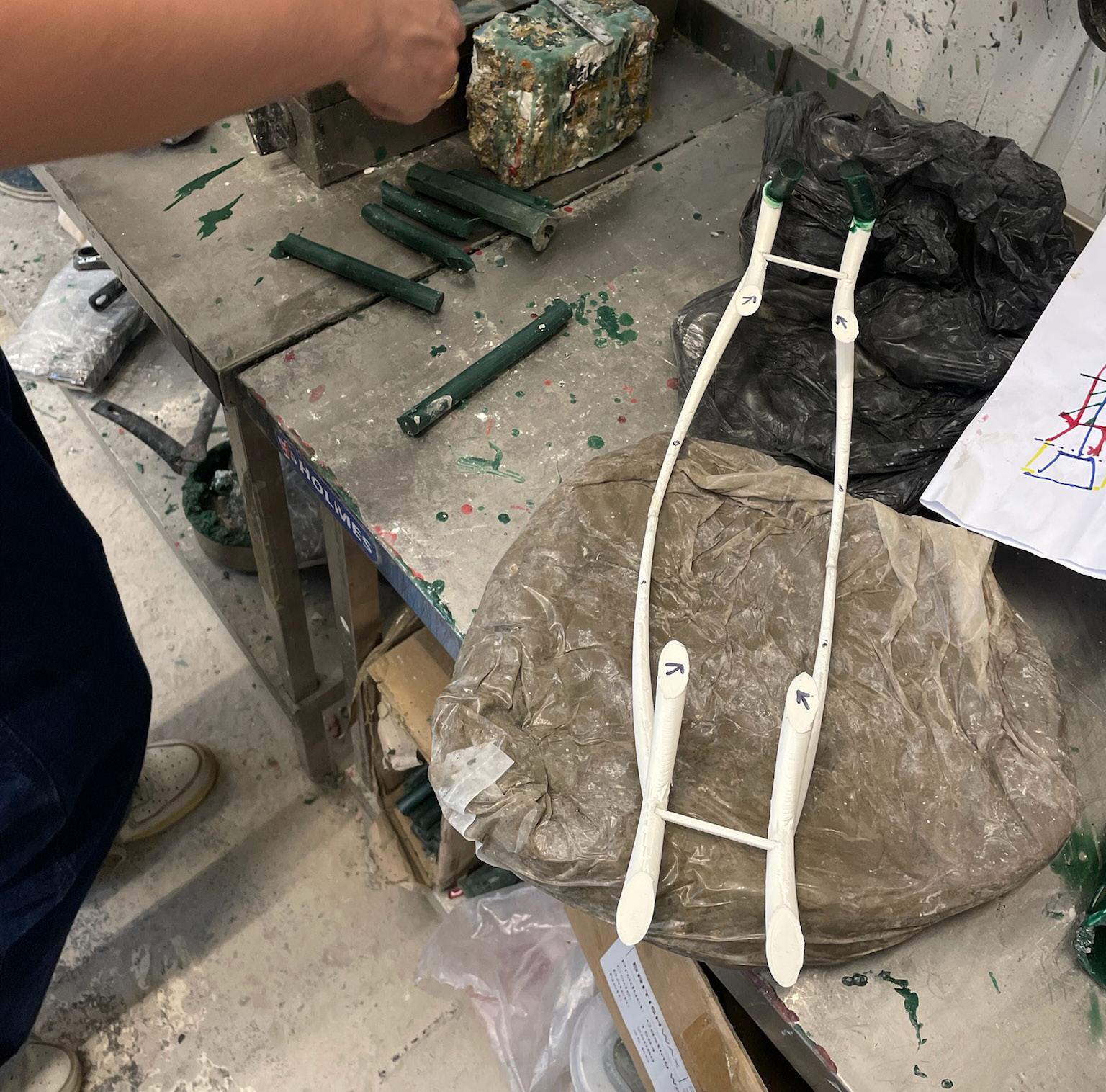
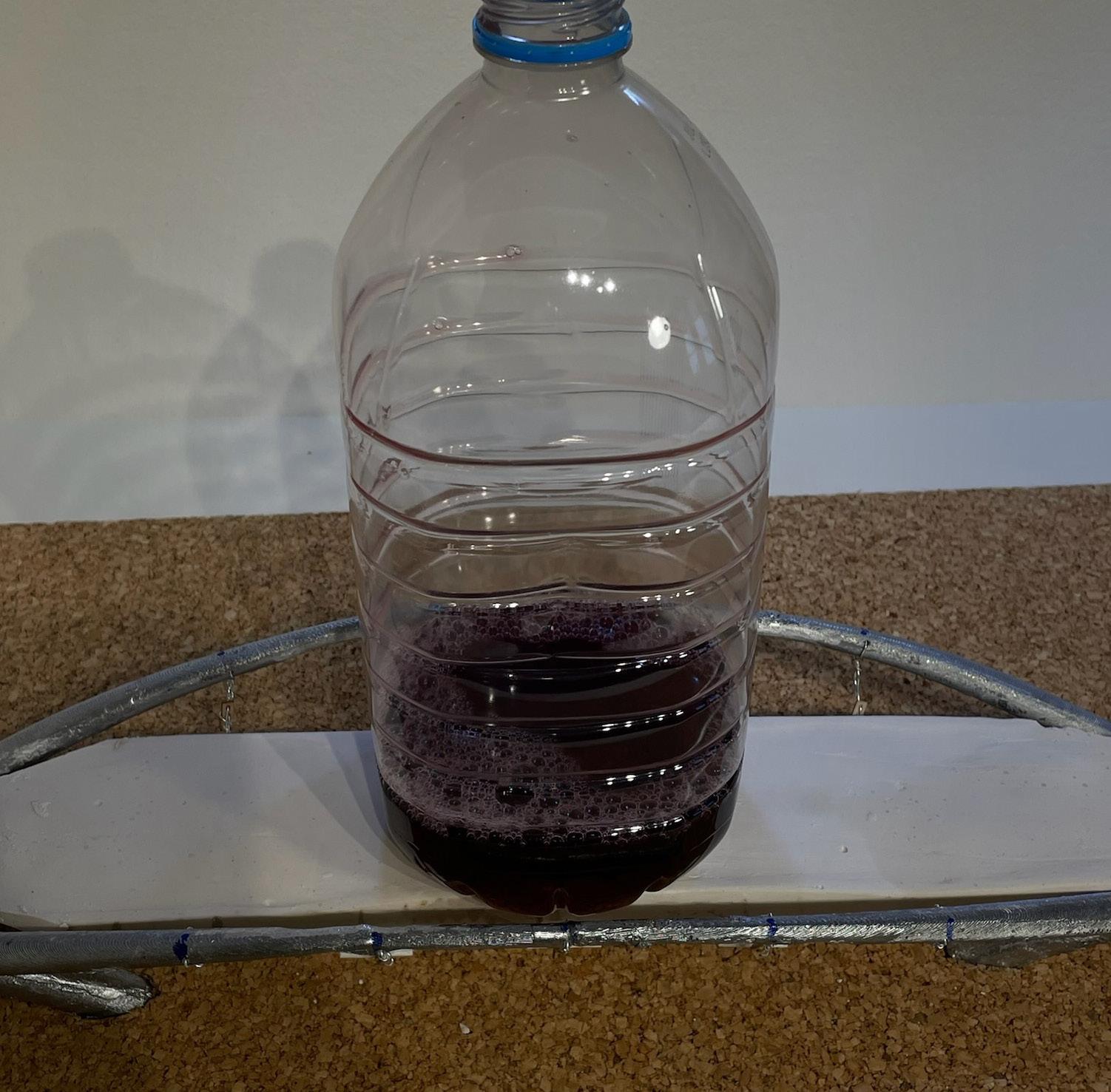
2. In order to cast the 3D printed form a mould must be constructed out of layered plaster as this has a higher melting point than aluminium:
First wax is fixed to the 3D print, located at sixteen different points across the model to ensure that the aluminiun flows through the mould and allows air to escape. A wax funnel is fixed to the wax tubing as a pouring point in the cast.
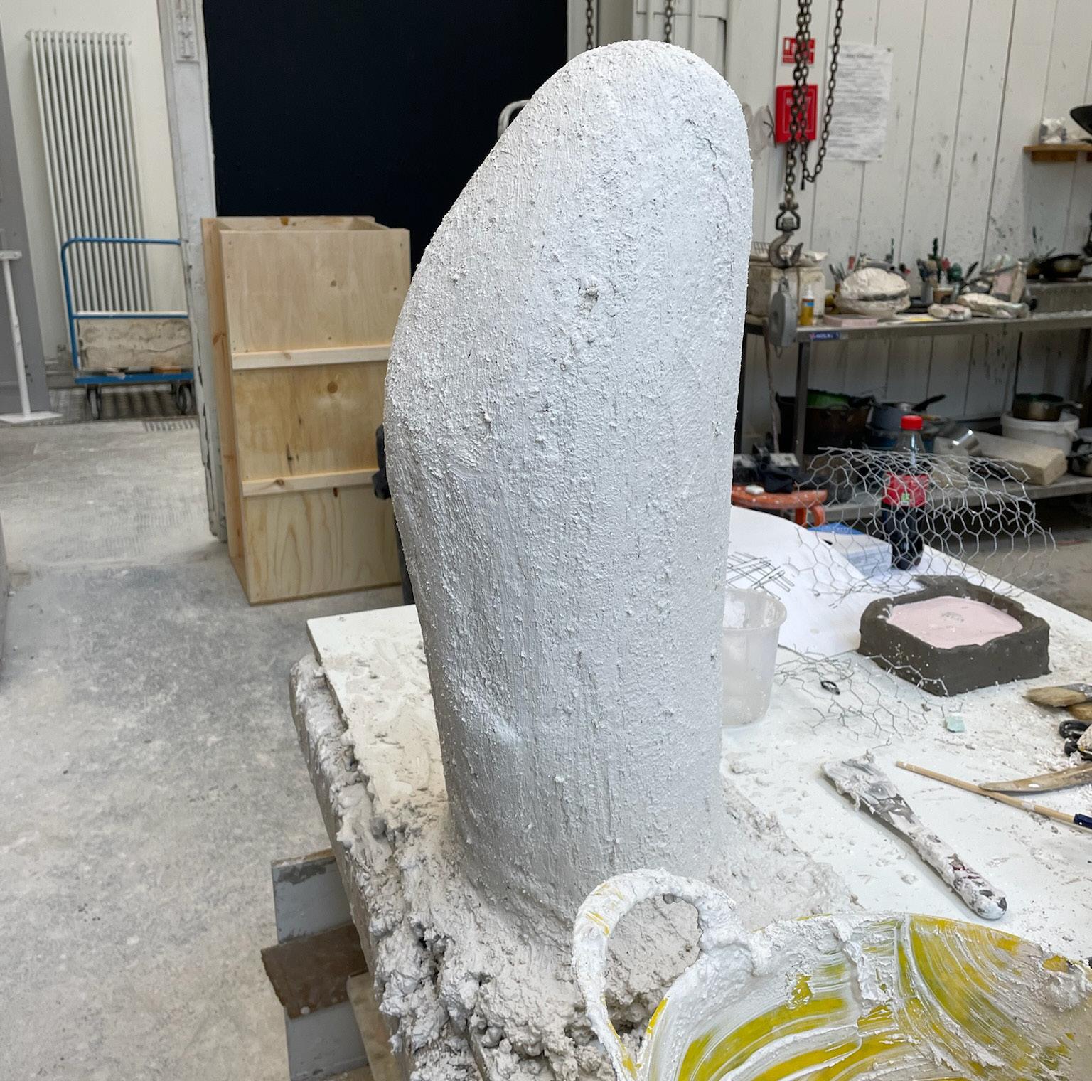
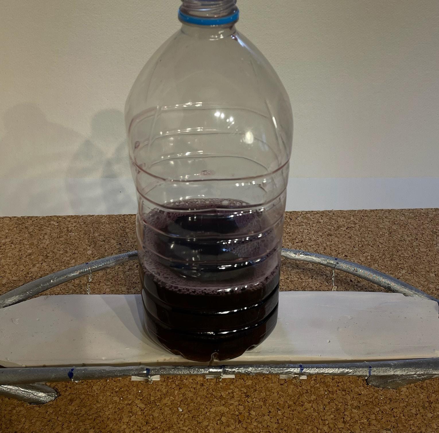
Plaster is first painted over the entirety of the wax and 3D print, ensuring that once the mould is entirely covered all gaps and crevices are sealed.
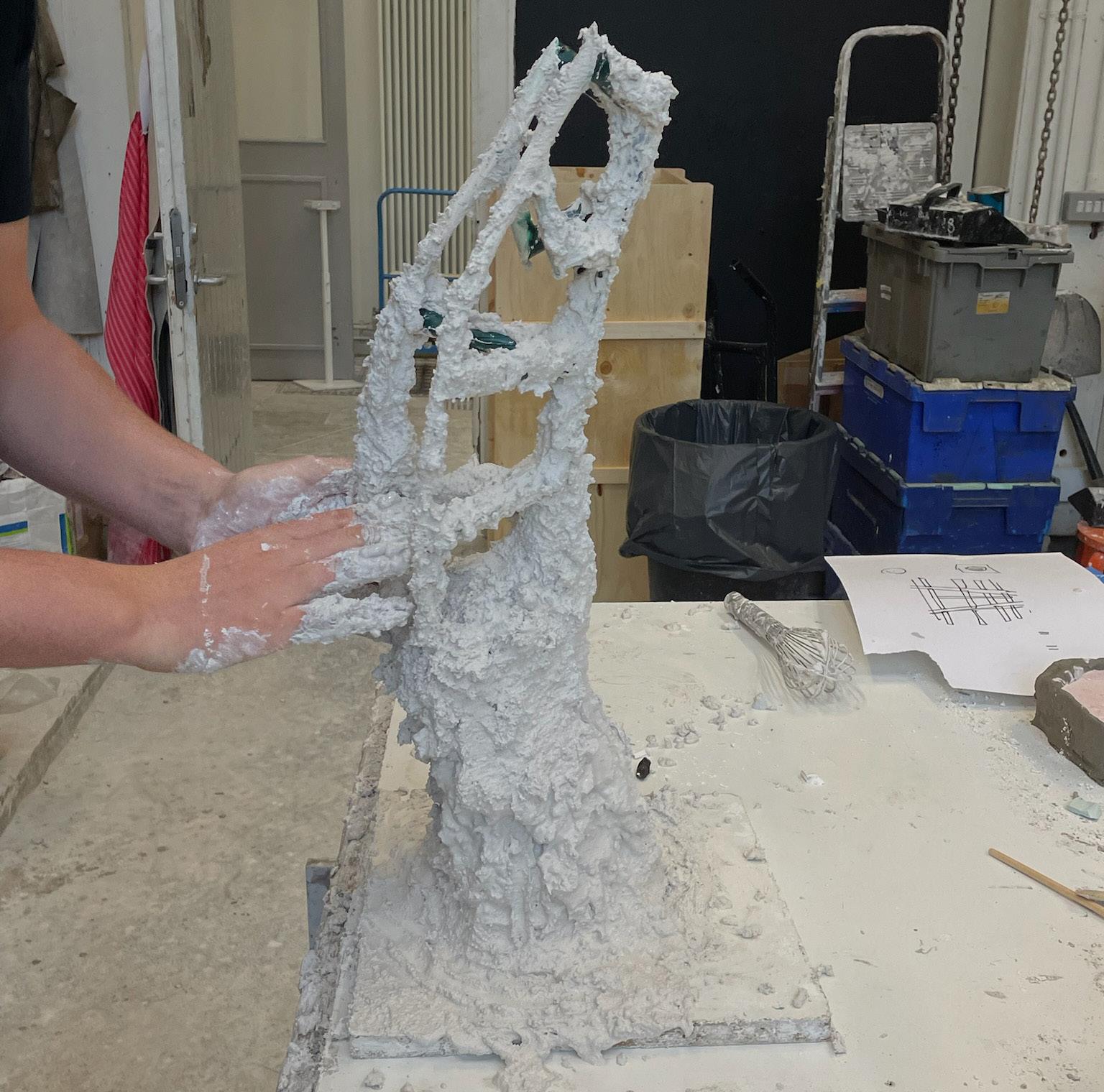
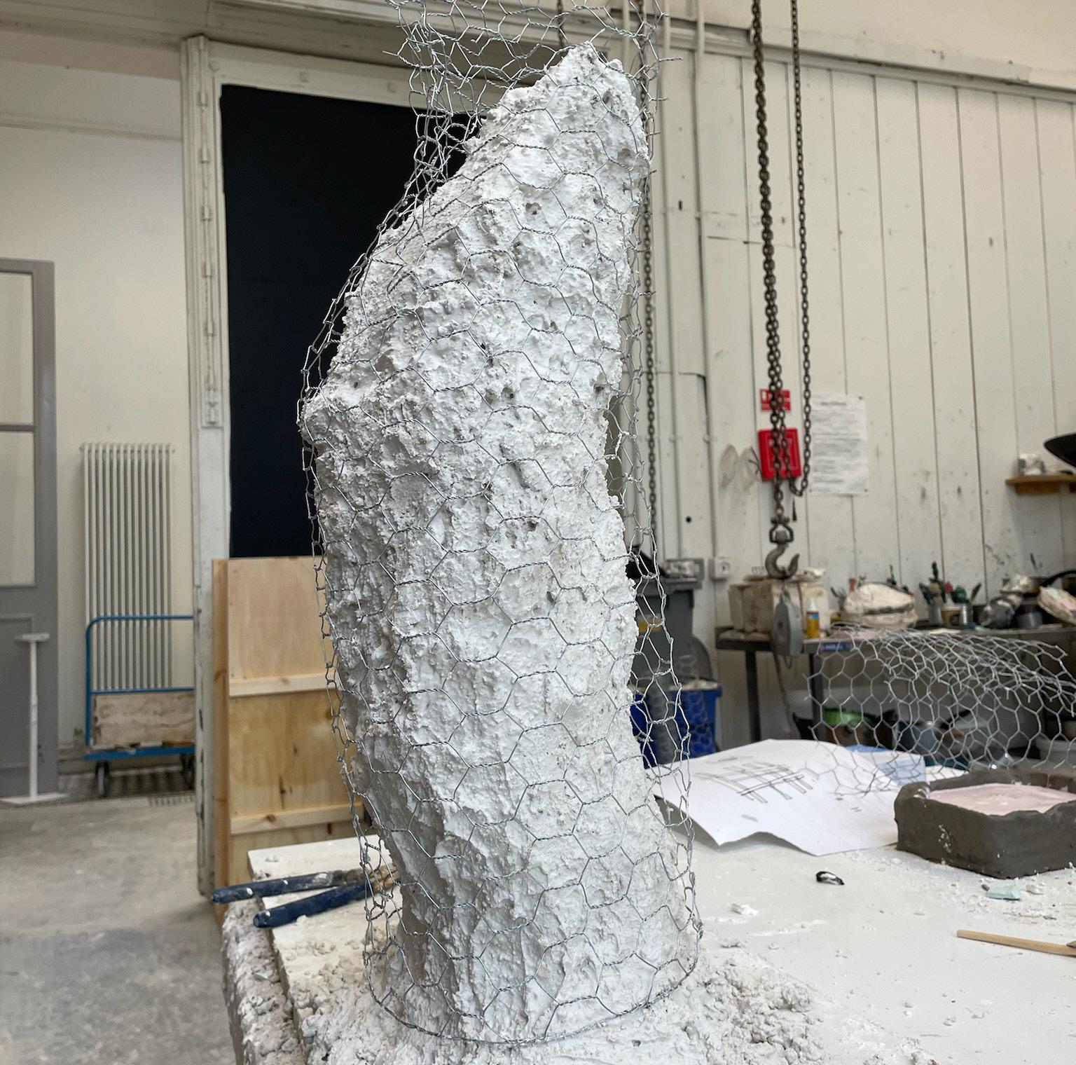
At this point the entirety of the form is covered in approximately 40Kg of plaster and chicken wire, applied by slowly pouring and multiple layers. The mould provides a heat proof casing to the form that mimics the exact exterior shape of the bridge.
Aluminium is heated to approximately 2600C using specialist blow torches and is poured directly into the wax funnel. The molten aluminium is left for 24 hrs to cool before breaking out of the mould.
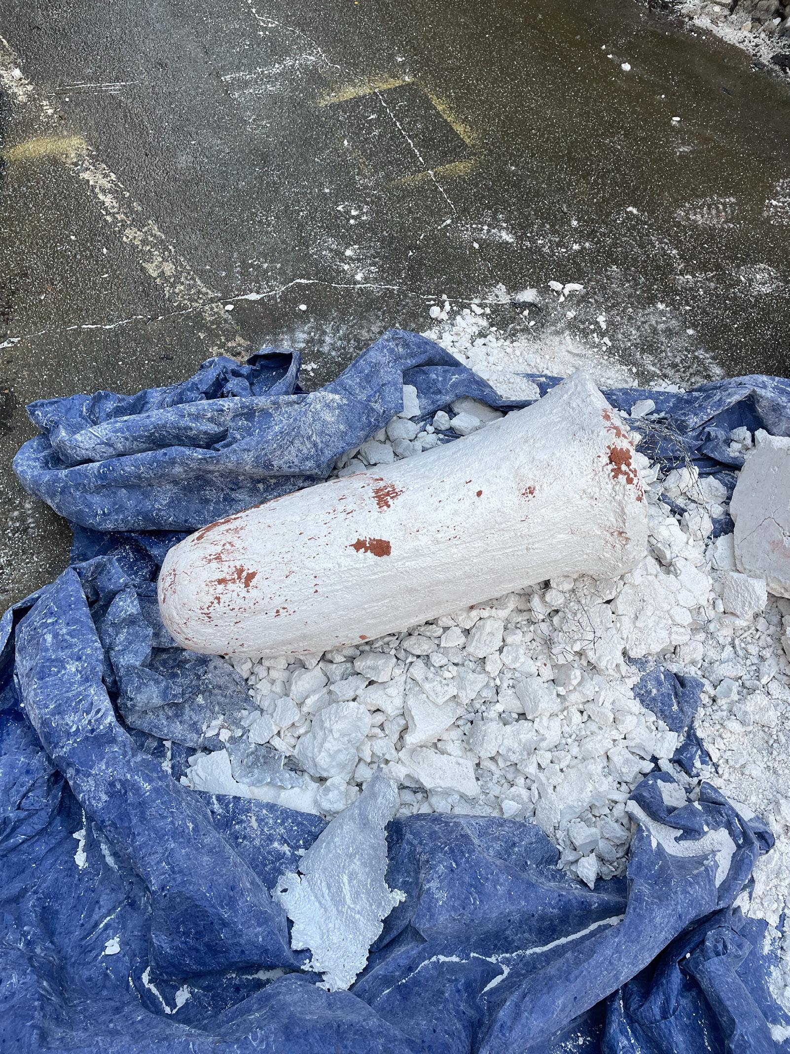
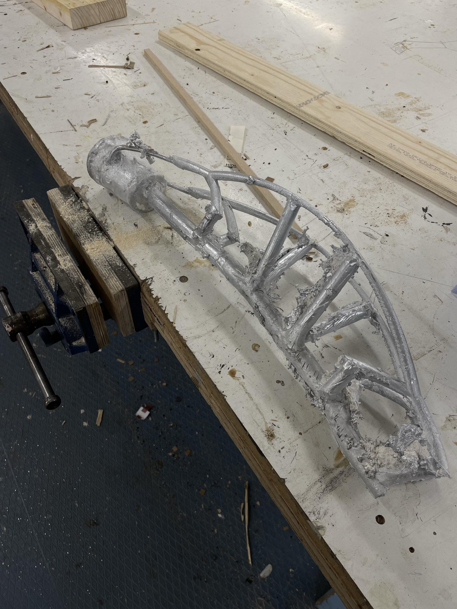
The plaster is then cracked and broken away from the aluminium using a chisel and hammer.
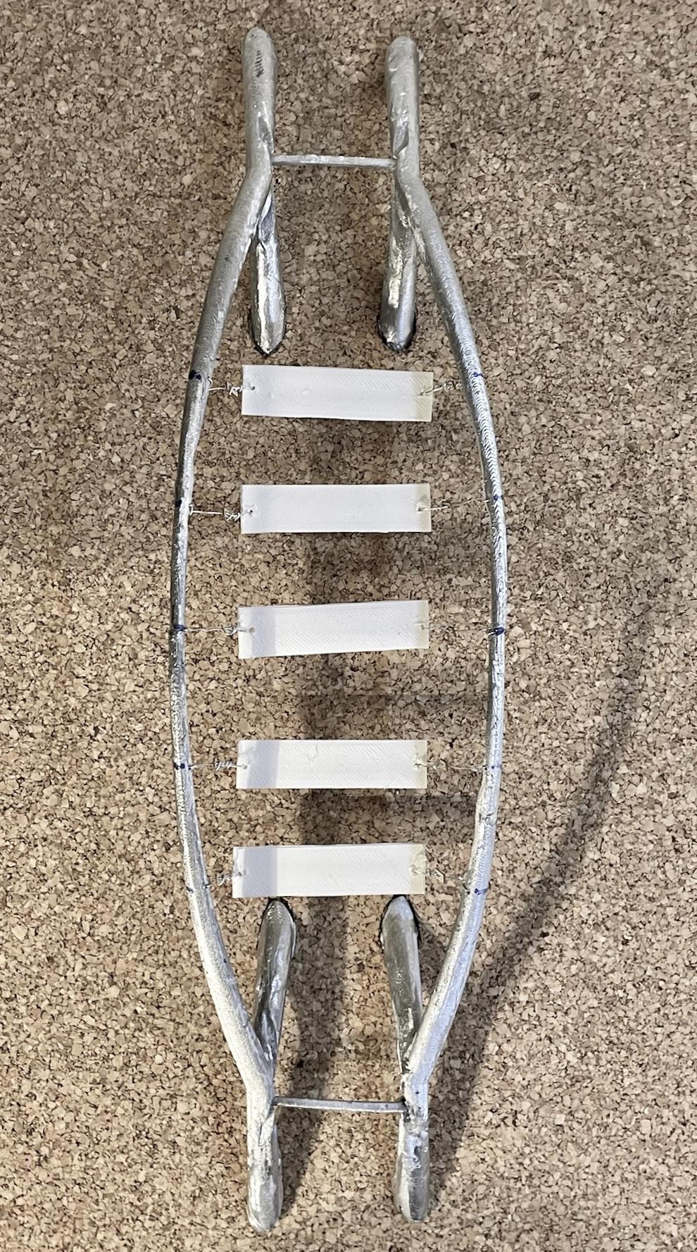
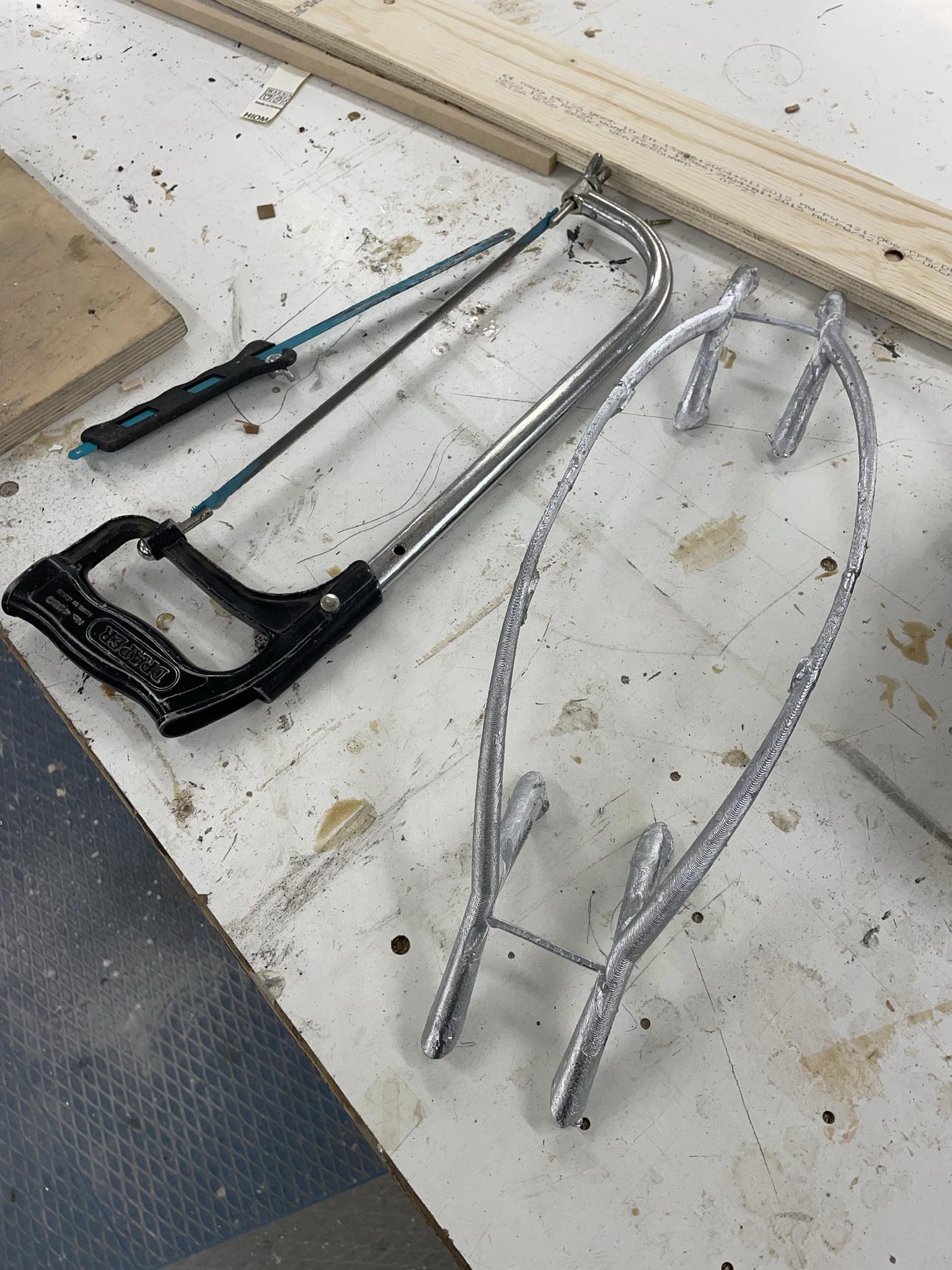
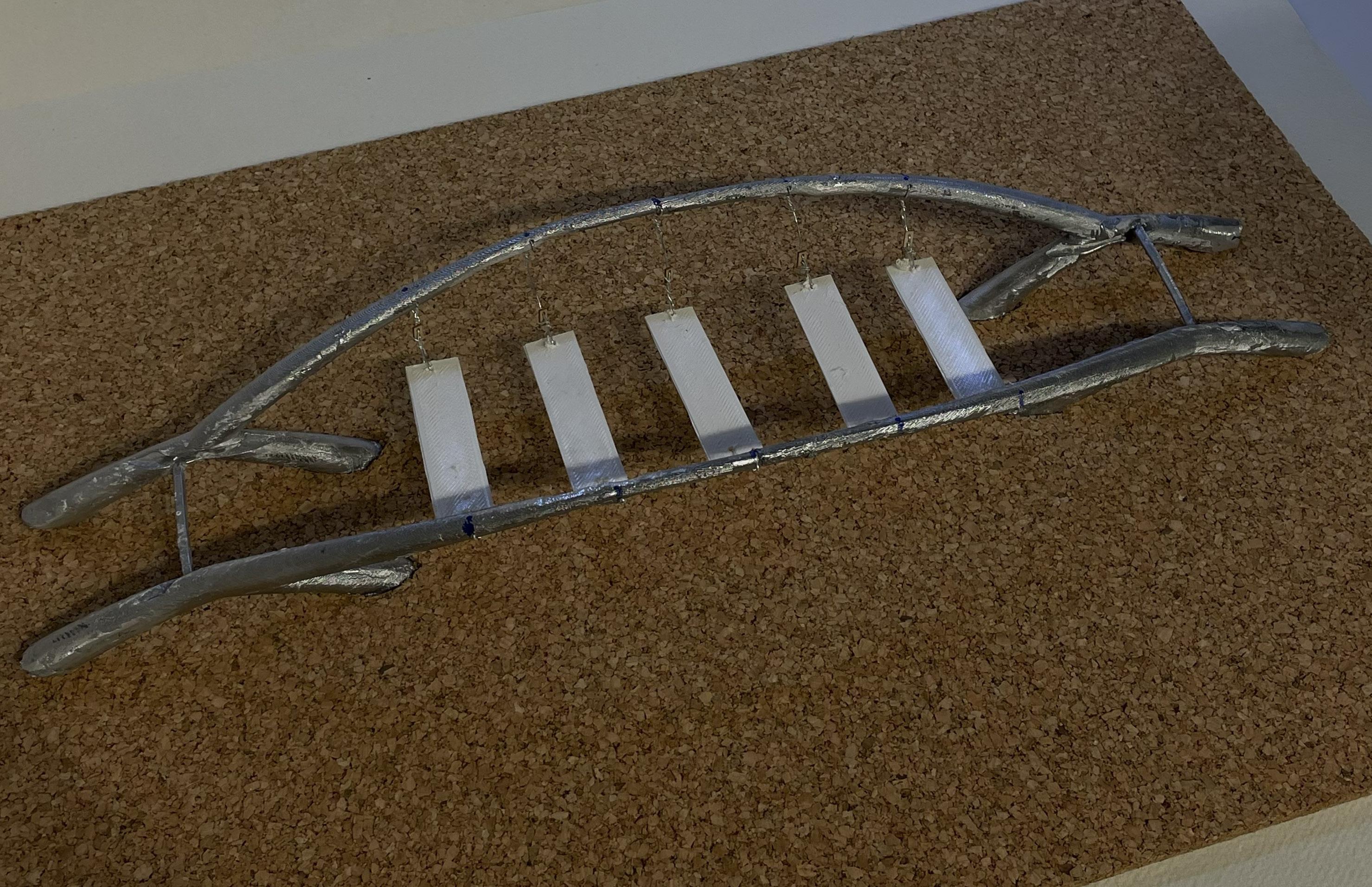
3. Using a combination of hand saws, band saws, angle grinders and soldering the finishing process is applied to the aluminium frame. This is to smooth off the frames exterior and disconnect it from the wax air way channels built into the mould that are now filled with aluminium.
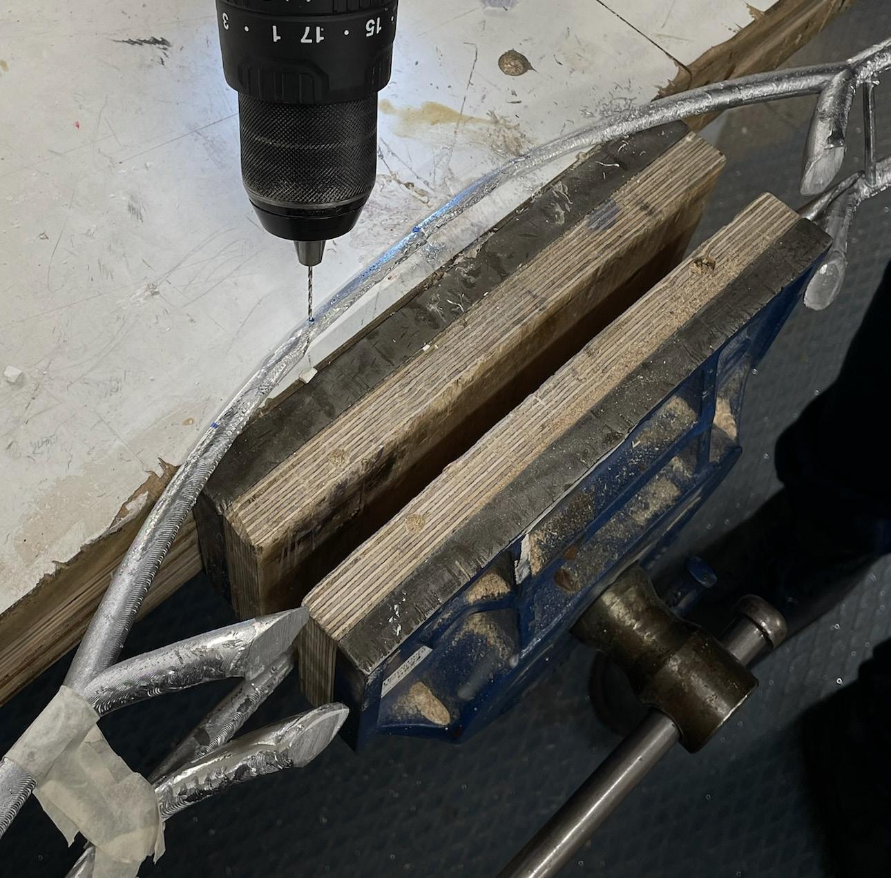
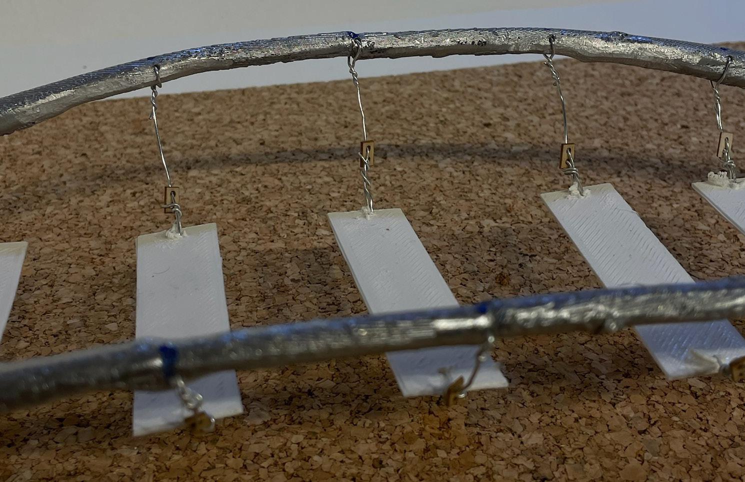
4. Holes are drilled through the aluminum frame at 5cm intervals to fix the wires.
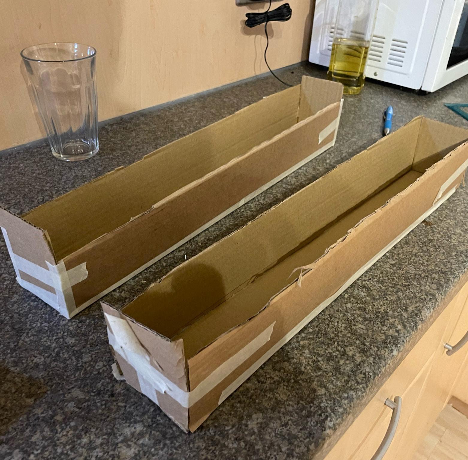
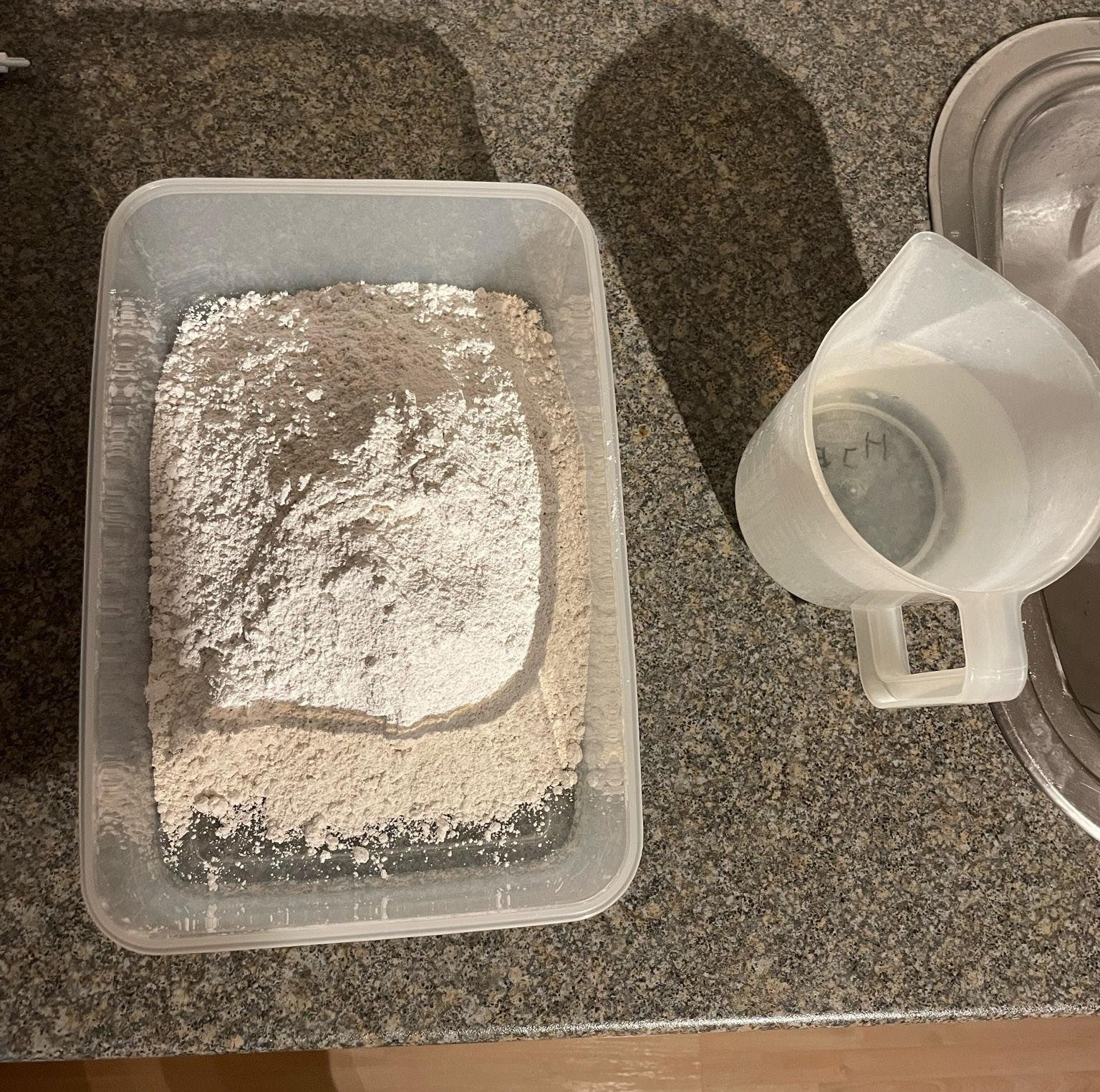
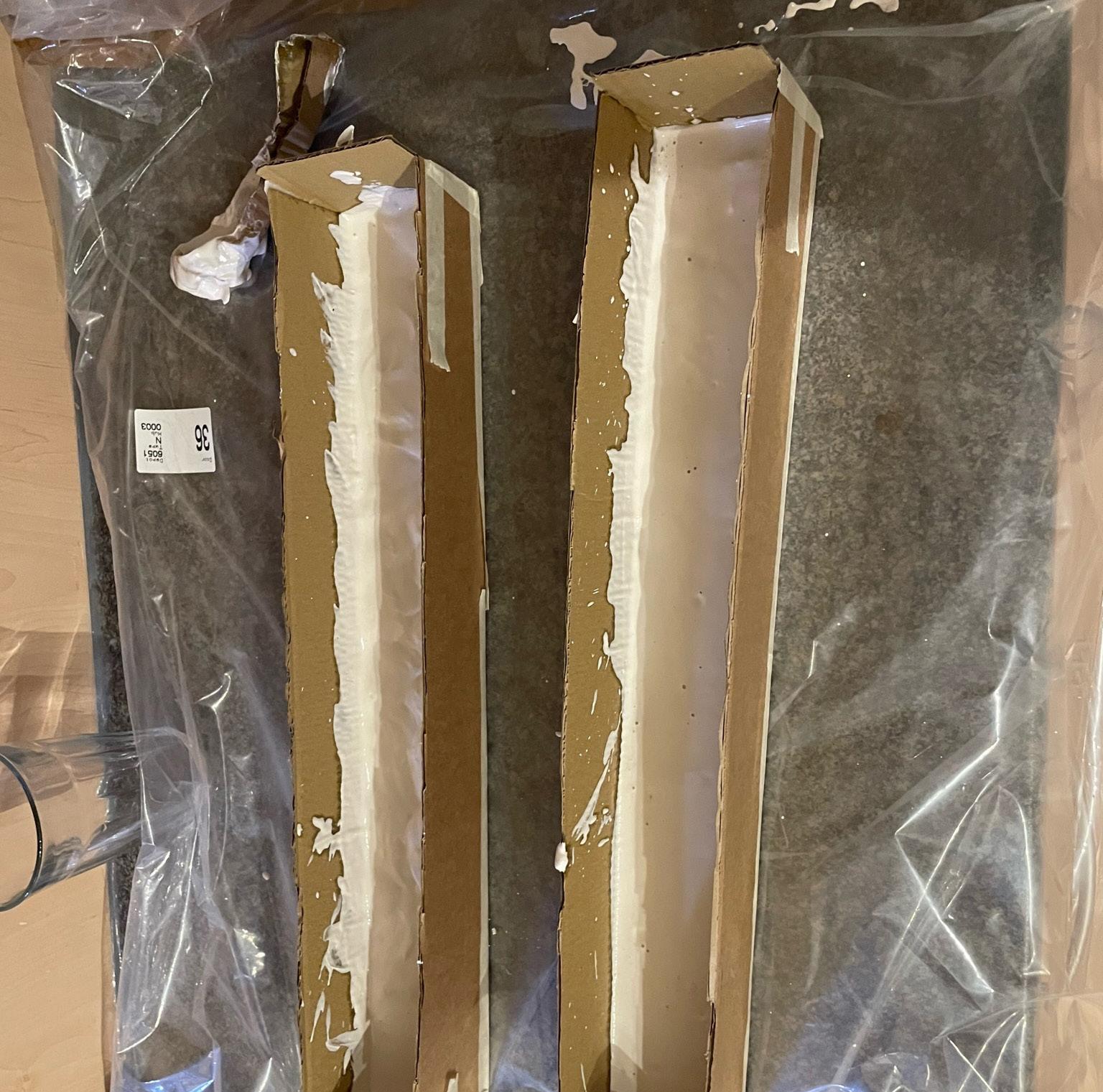
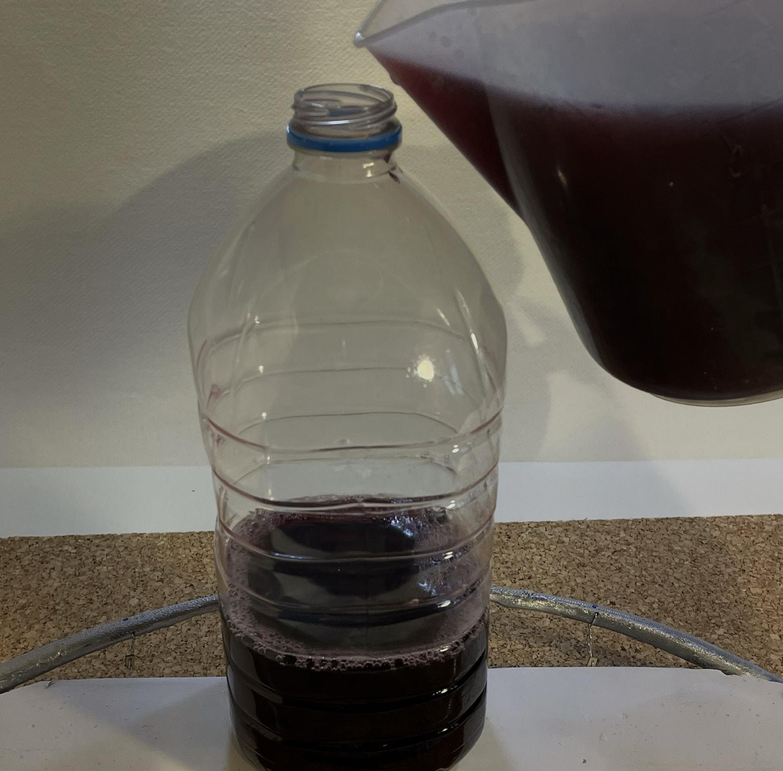
5. The concrete deck is constructed using plaster cast: A mould is constructed using cardboard and tape to the dimensions specified on the original rhino model
A plaster cast paste is created using plaster powder and warm water at a ratio of 2:1
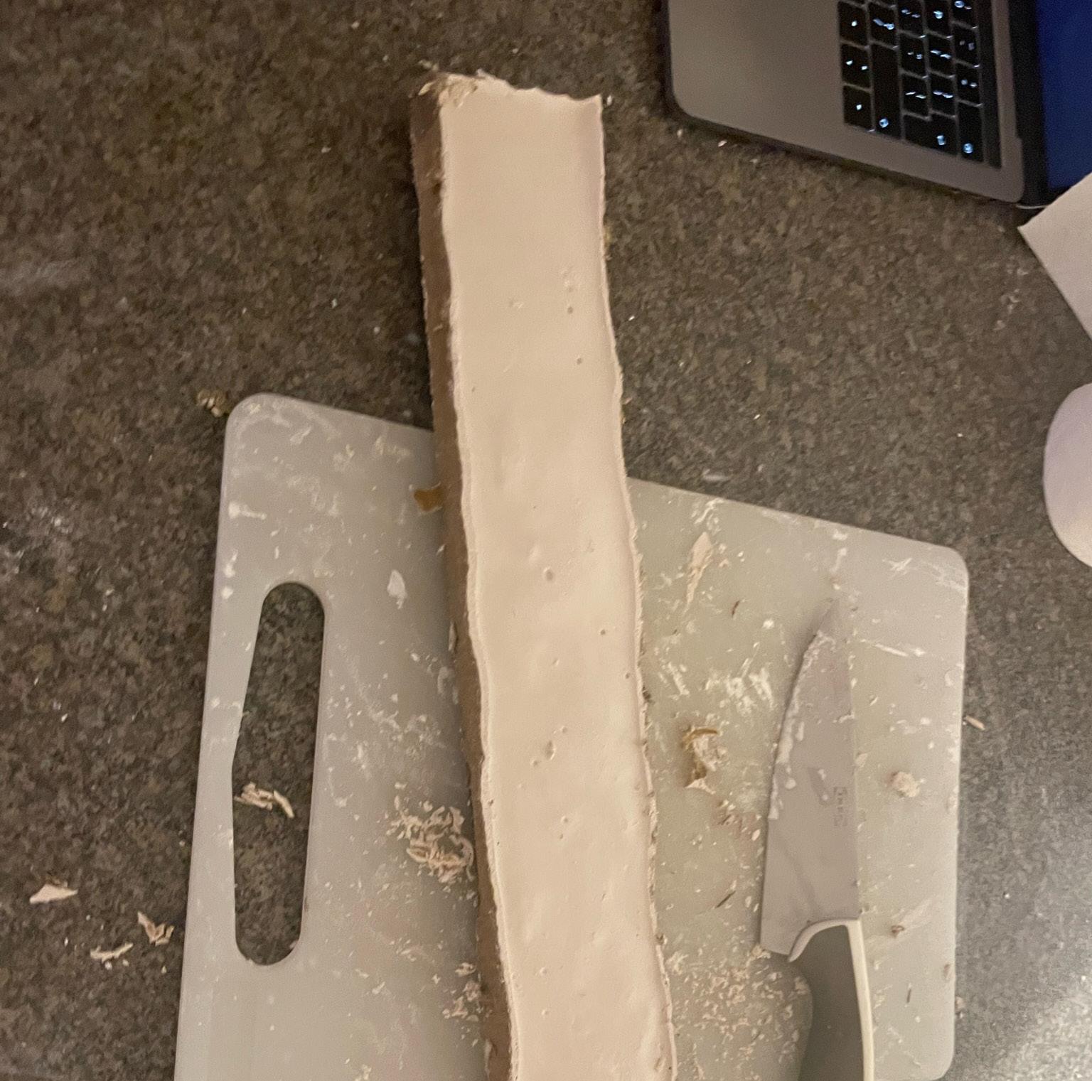
This is poured and left for 3 hrs to cure.
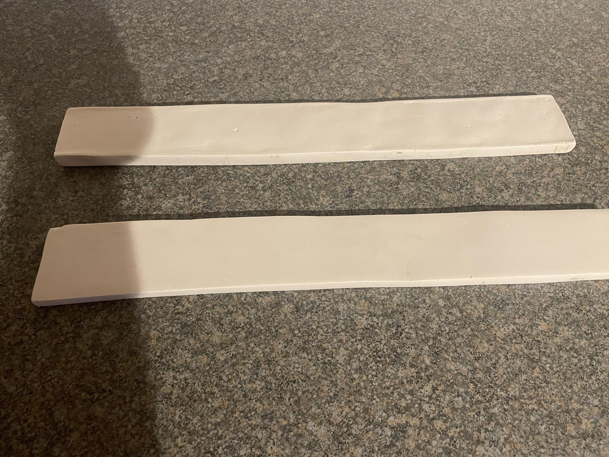
The cardboard mould is then removed, and the plaster is sanded and smoothed with water and a cloth until reaching the final form.
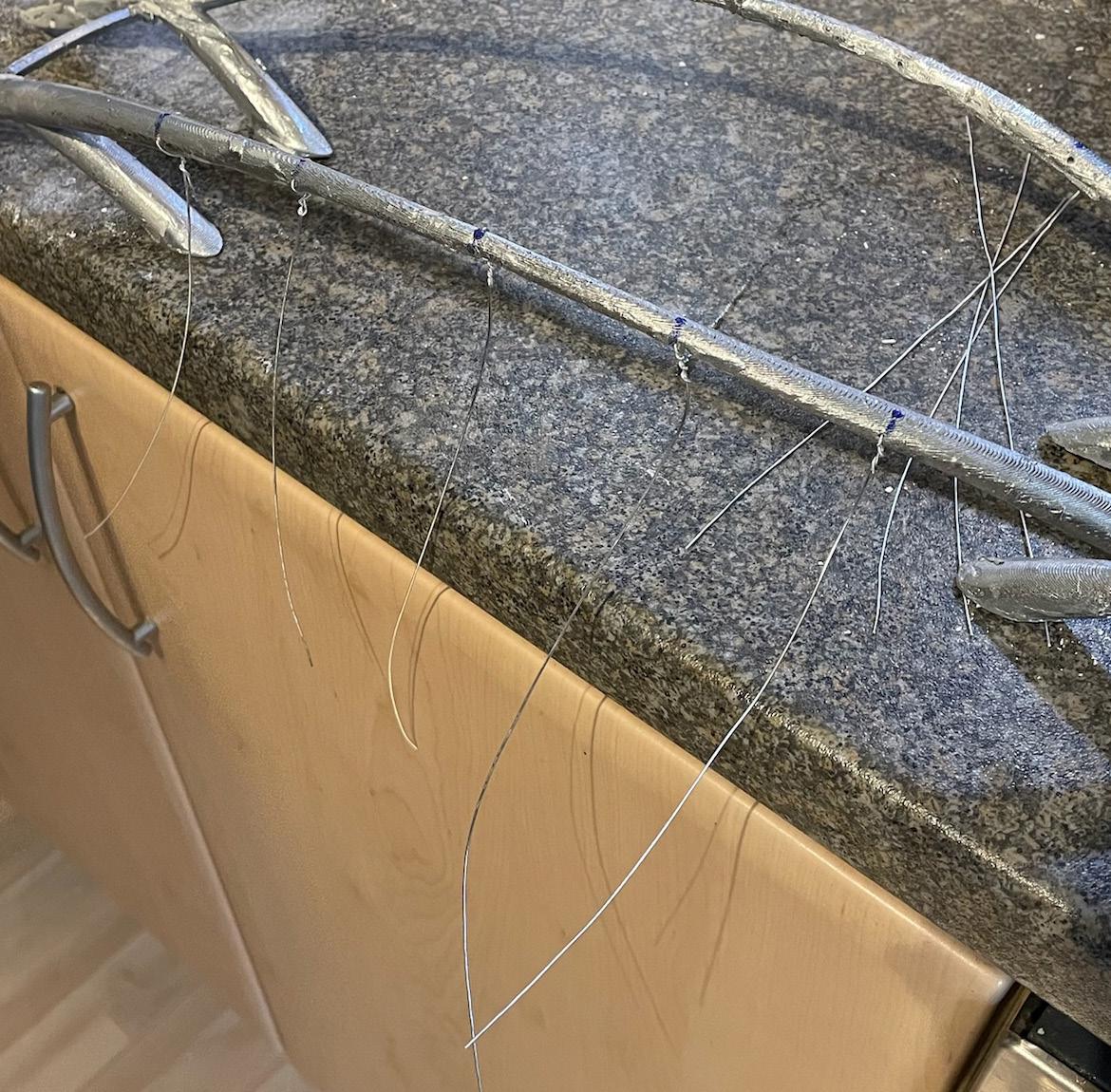
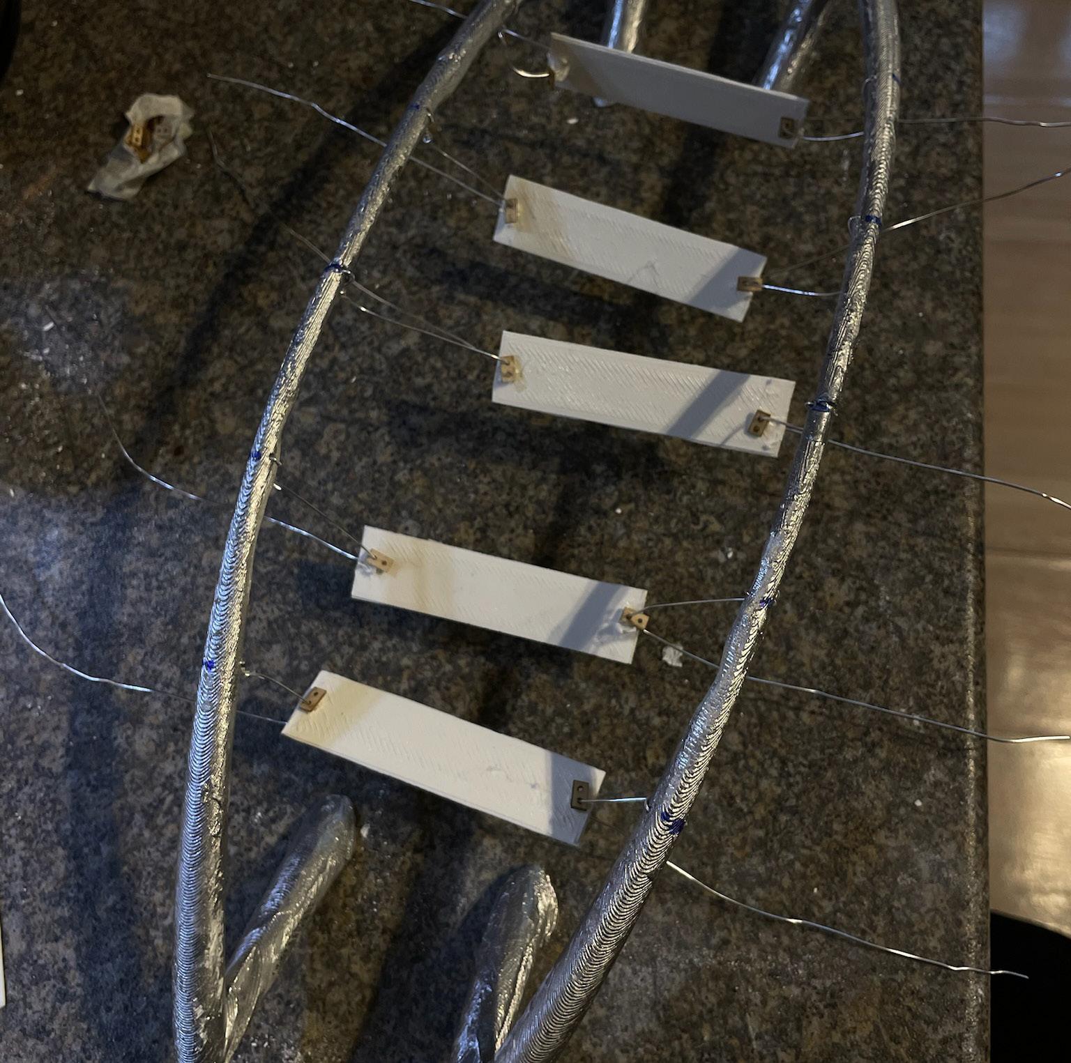
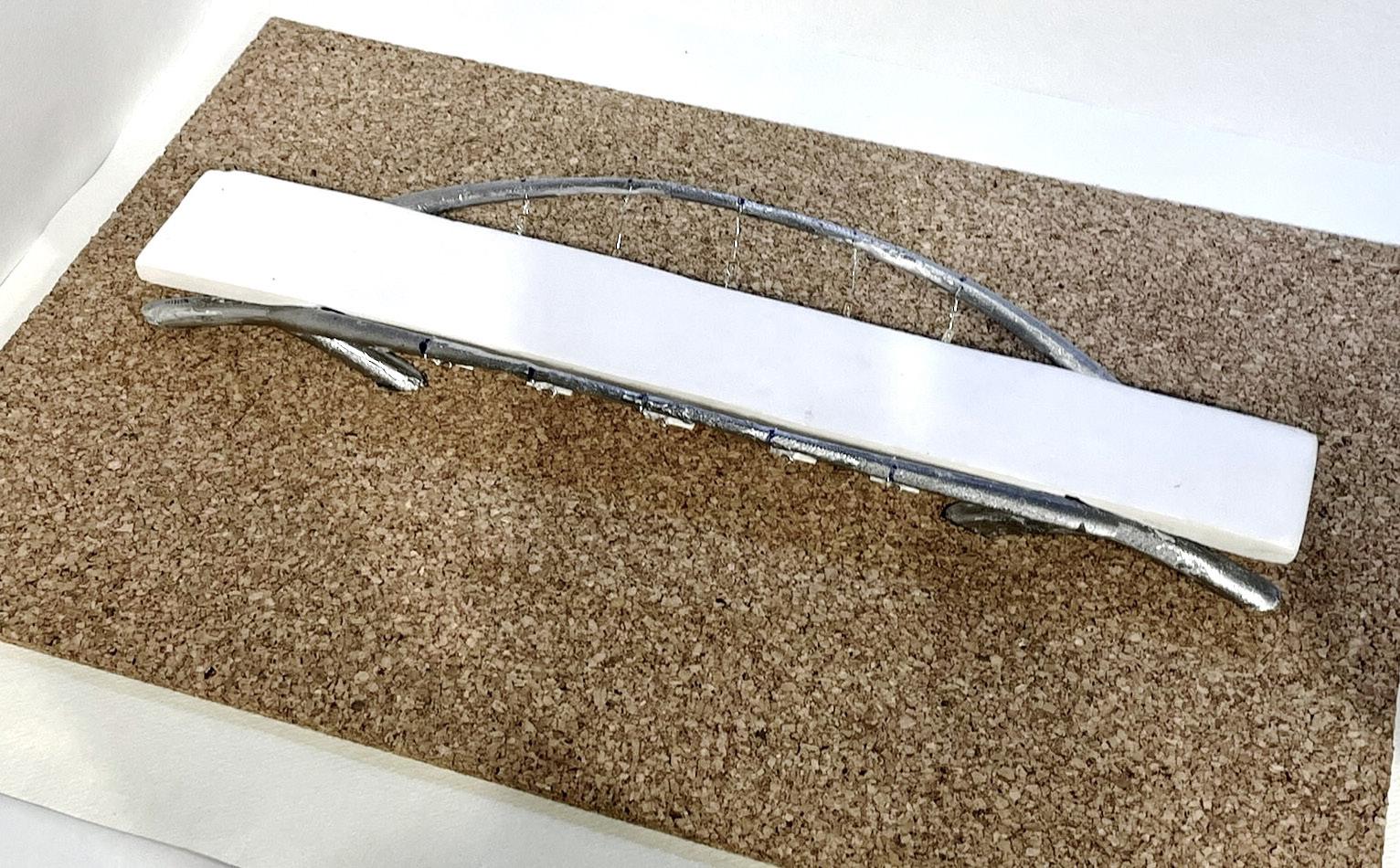
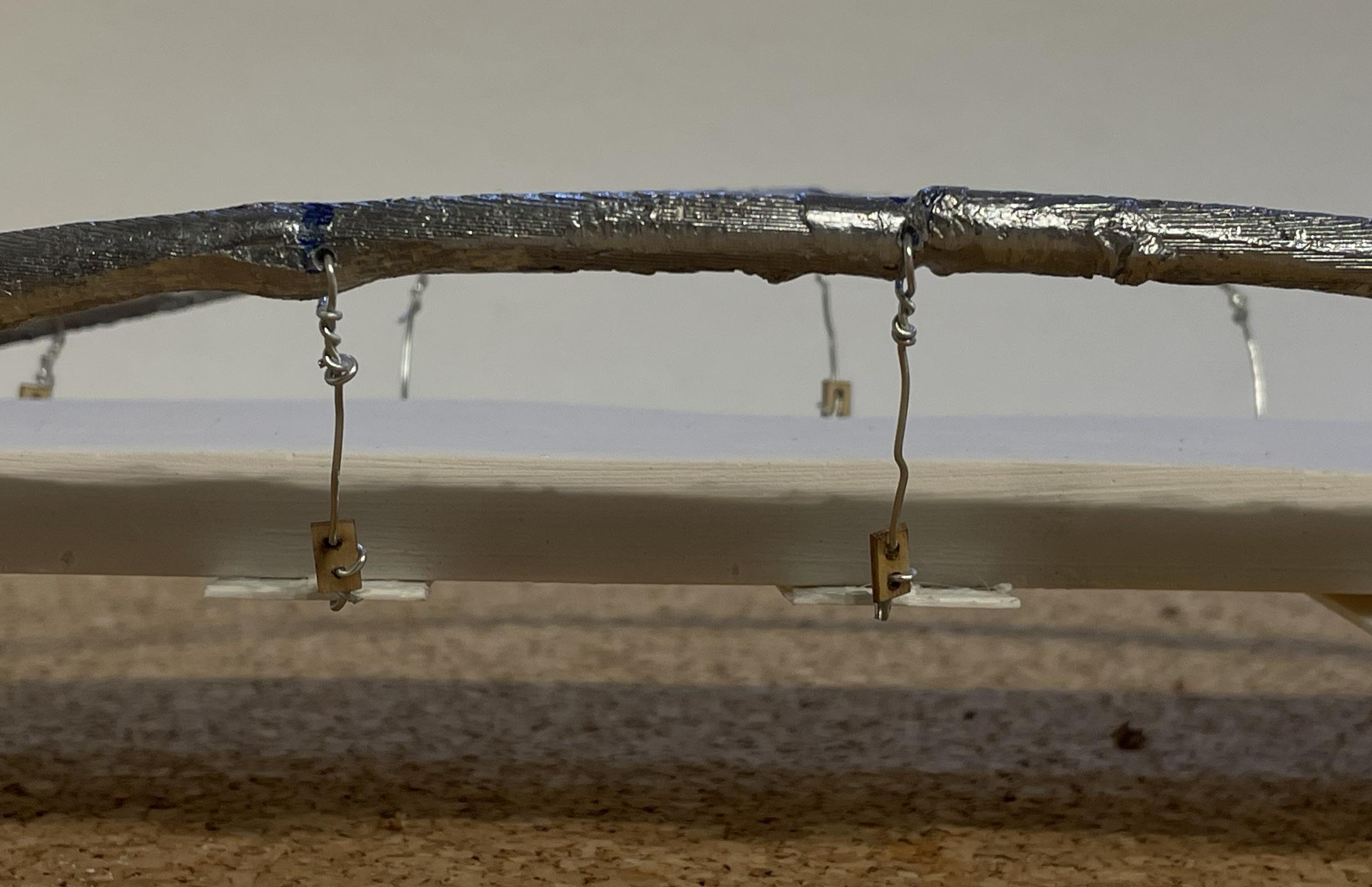
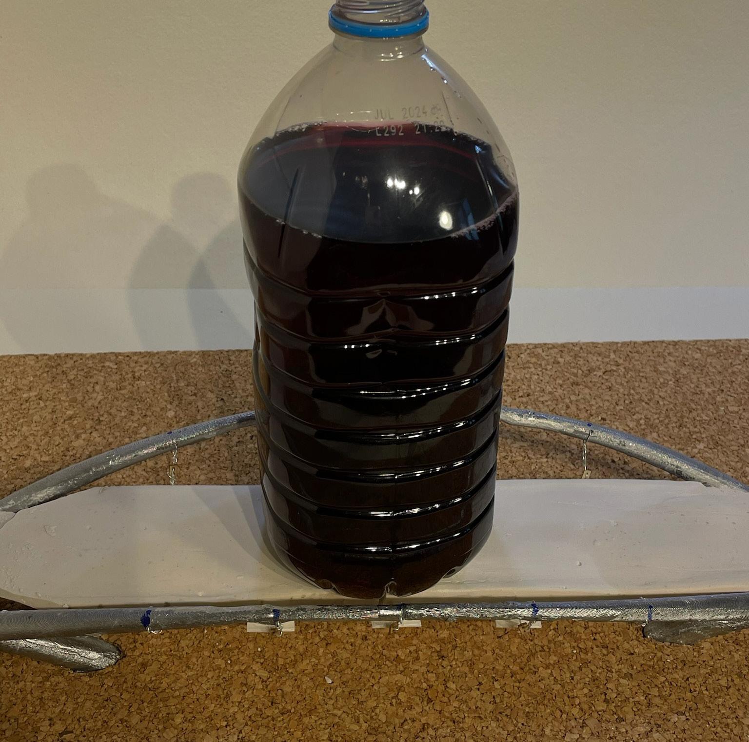
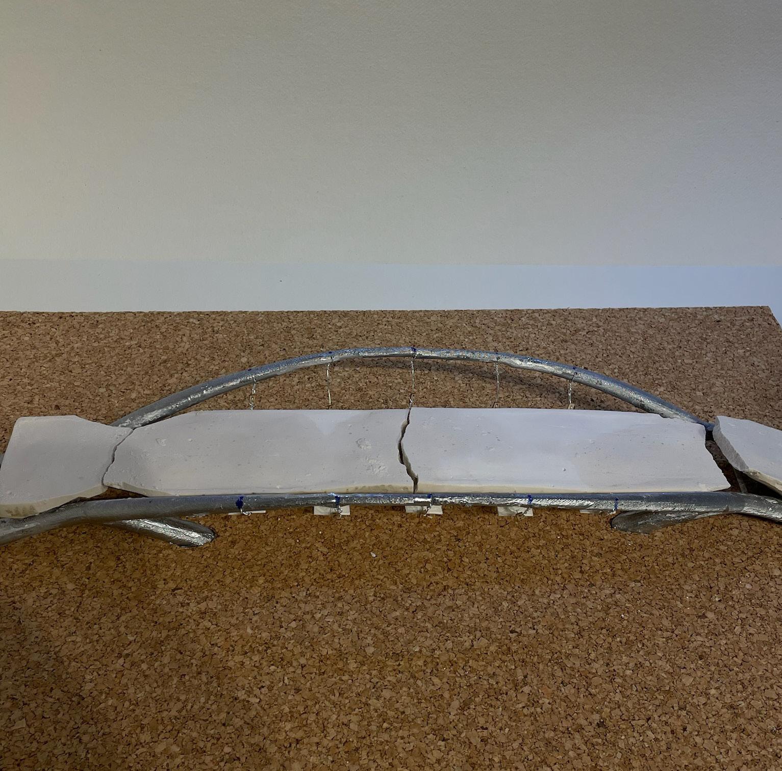
6. Assembly: Wires are placed through the holes of the frame twisted tight and trimmed acting as the fixed anchorage point.
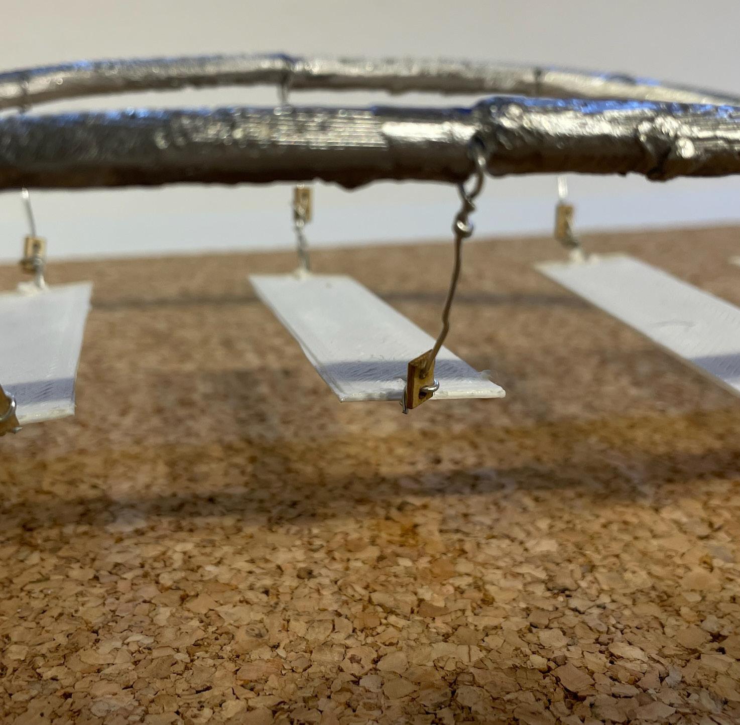
The wires are loosely fixed to the 3D printed stringers and wooden cleats.
The plaster cast deck is fixed in place and the wires are pulled tight through the cleat. Once the wire is in tension, the cleat and wire is fixed into place.
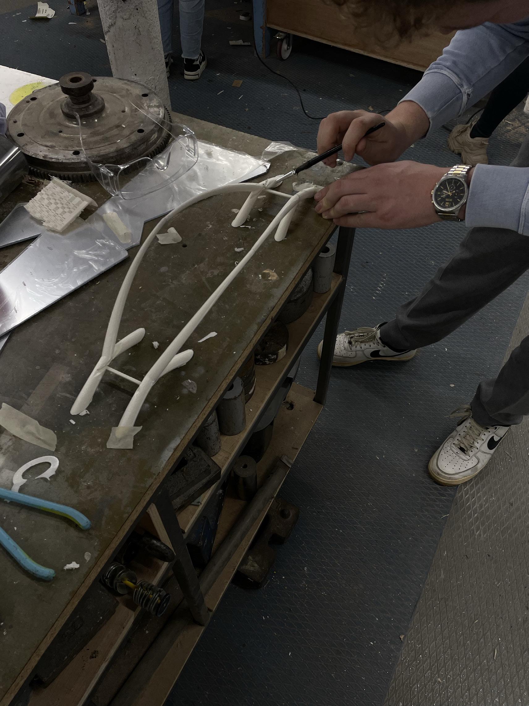
FABRICATION - WAX AND PLASTER CAST
FABRICATION - ALUMINUM FRAME


Chen, Baochun, Jiangang Wei, and Junping Liu. Concrete-filled steel tubular arch bridges. Singapore: Springer, 2023.
Crook , Lizzie. “Sculptural Steel Arches Support Jiangxi River Bridge by Zaha Hadid Architects.” Dezeen, August 17, 2023. https://www.dezeen. com/2023/08/17/steel-arches-jiangxi-river-bridge-zaha-hadid-architects/.
Knebel, Klaus & Sanchez-Alvarez, Jaime & Zimmermann, S.. (2001). The Eden Project - Design, fabrication and assembly of the largest greenhouse of the world. 70. 513-525.
Melbourne, Prof C. Arch Bridges. Salford: University of Salford, n.d.
Middleton, Campbell R.). Bridge Monitoring. ICE Publishing, n.d.
Möller, Eberhard. Manual of Structural Design: Structural Principles, suitable spans, inspiring works. Munich (DE): Edition Detail, 2022.