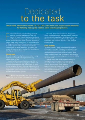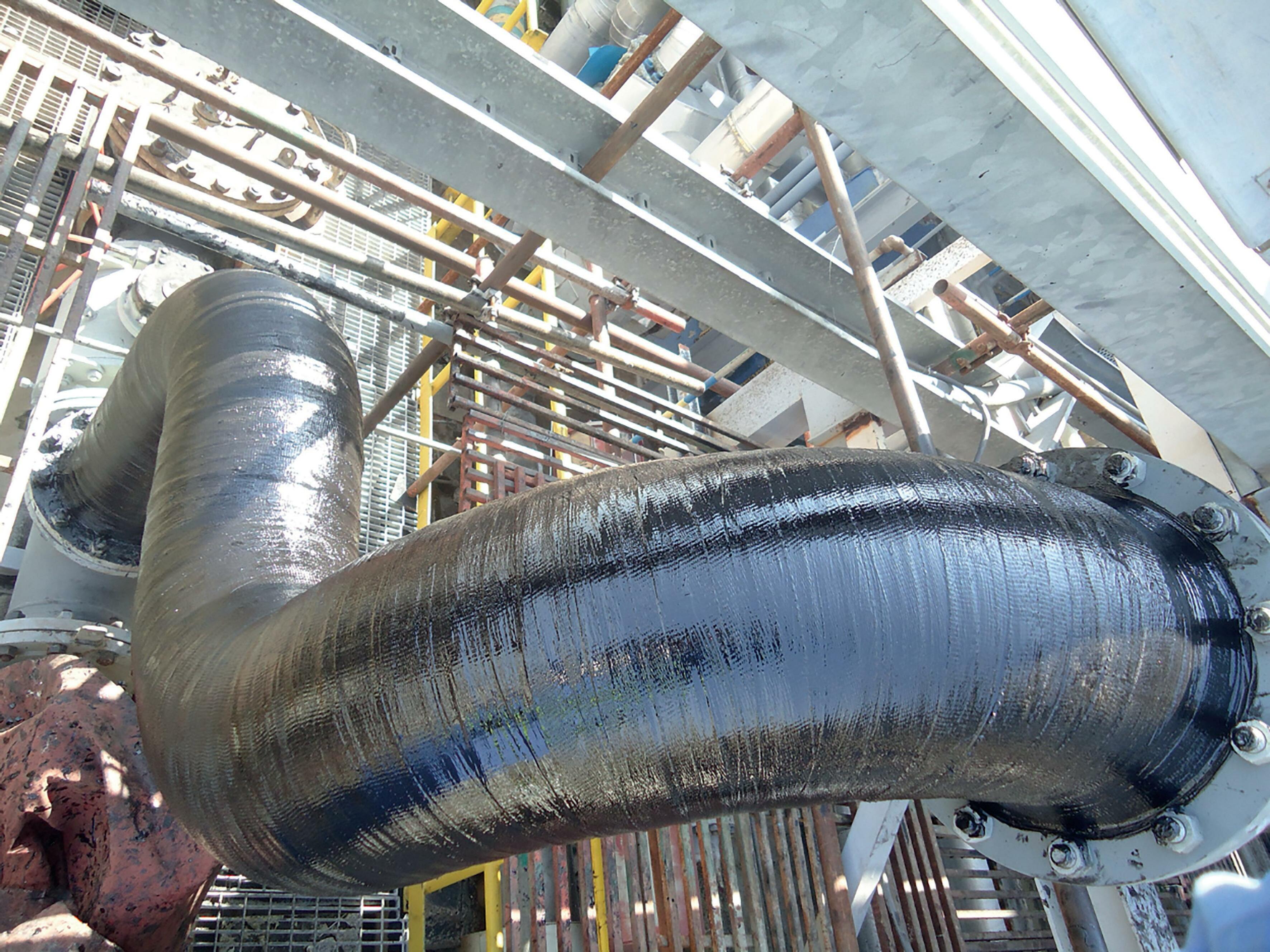
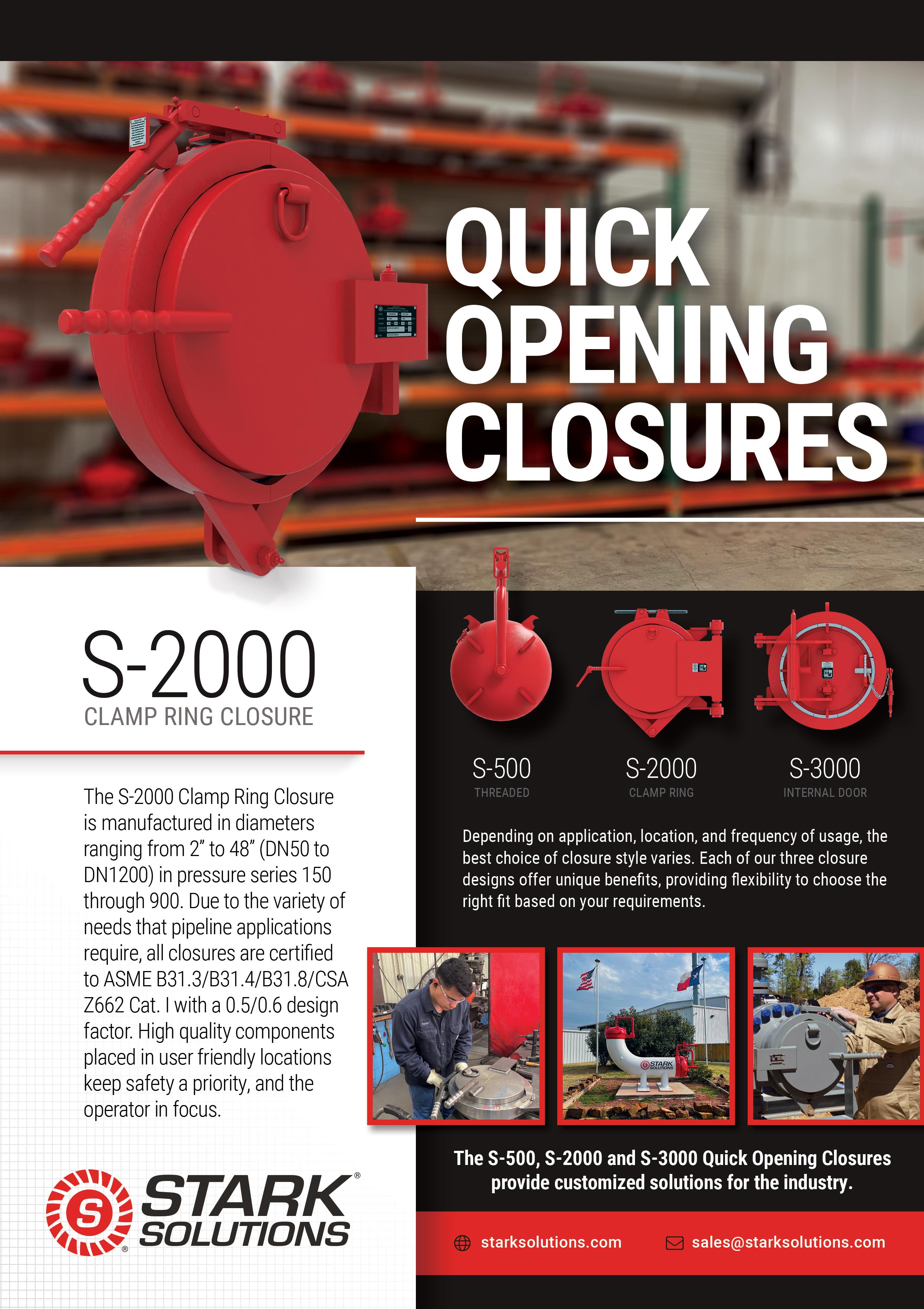
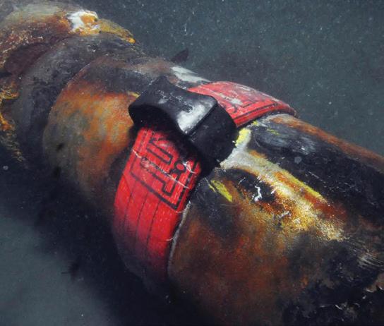
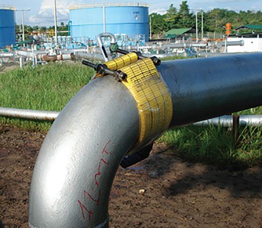
ONSHORE /OFFSHORE OIL & GAS SECURES YOUR INSTALLATIONS IN ANY ENVIRONMENTS INNOVATIVE REPAIR SOLUTIONS FOR YOUR INSTALLATIONS www.3xeng.com HIGH PERFORMANCE COMPOSITE REPAIR SOLUTION FOR PIPE REINFORCEMENT REINFORCEKiT®4D ® Volume 22 Number 12 - December 2022
The leading innovator supplying cutting-edge integrity solutions. Together we can ensure sustainable decision-making. Our combination of advanced inspection systems and expert consultants delivers a comprehensive understanding of asset safety, lifetime, and performance.
Comprehensive Asset Integrity Management

www.rosen-group.com
comment

SENSING


THOUGHT LEADERSHIP:
REPAIR AND REHABILITATION SERVICES


45. Prolonging the life of assets Jim Bramlett, Tracerco, USA.


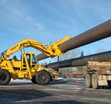
PIPELINE MACHINERY FOCUS 49. Dedicated to the task Mitch Fedie, Pettibone/Traverse Lift LLC, USA.
TUBE AND PIPE 51. Detecting weld defects Cameron Serles, President, Xiris Automation Inc., Canada.


TOOL PERFORMANCE

ISSN 14727390 Member of ABC Audit Bureau of Circulations
Reader
C O NTENTS Copyright© Palladian Publications Ltd 2022. All rights reserved. No part of this publication may be reproduced, stored in a retrieval system, or transmitted in any form or by any means, electronic, mechanical, photocopying, recording or otherwise, without the prior permission of the copyright owner. All views expressed in this journal are those of the respective contributors and are
the opinions of the publisher, neither do the publishers endorse any of the claims made in the articles or the advertisements. Printed
the UK.
|
|
|
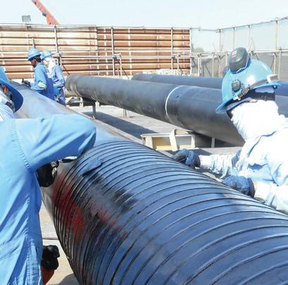
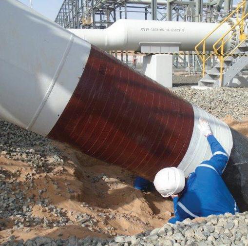
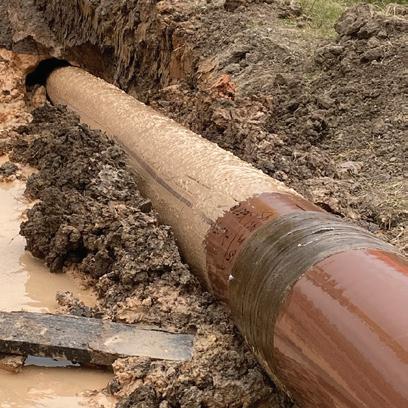
3X ENGINEERING
pipeline maintenance
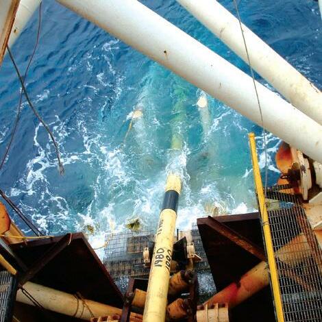
ON THIS MONTH'S COVER
enquiries [www.worldpipelines.com]
not necessarily
in
WORLD PIPELINES
VOLUME 22
NUMBER 12
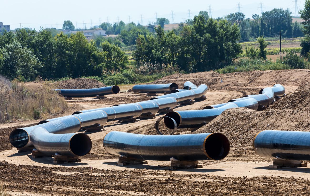
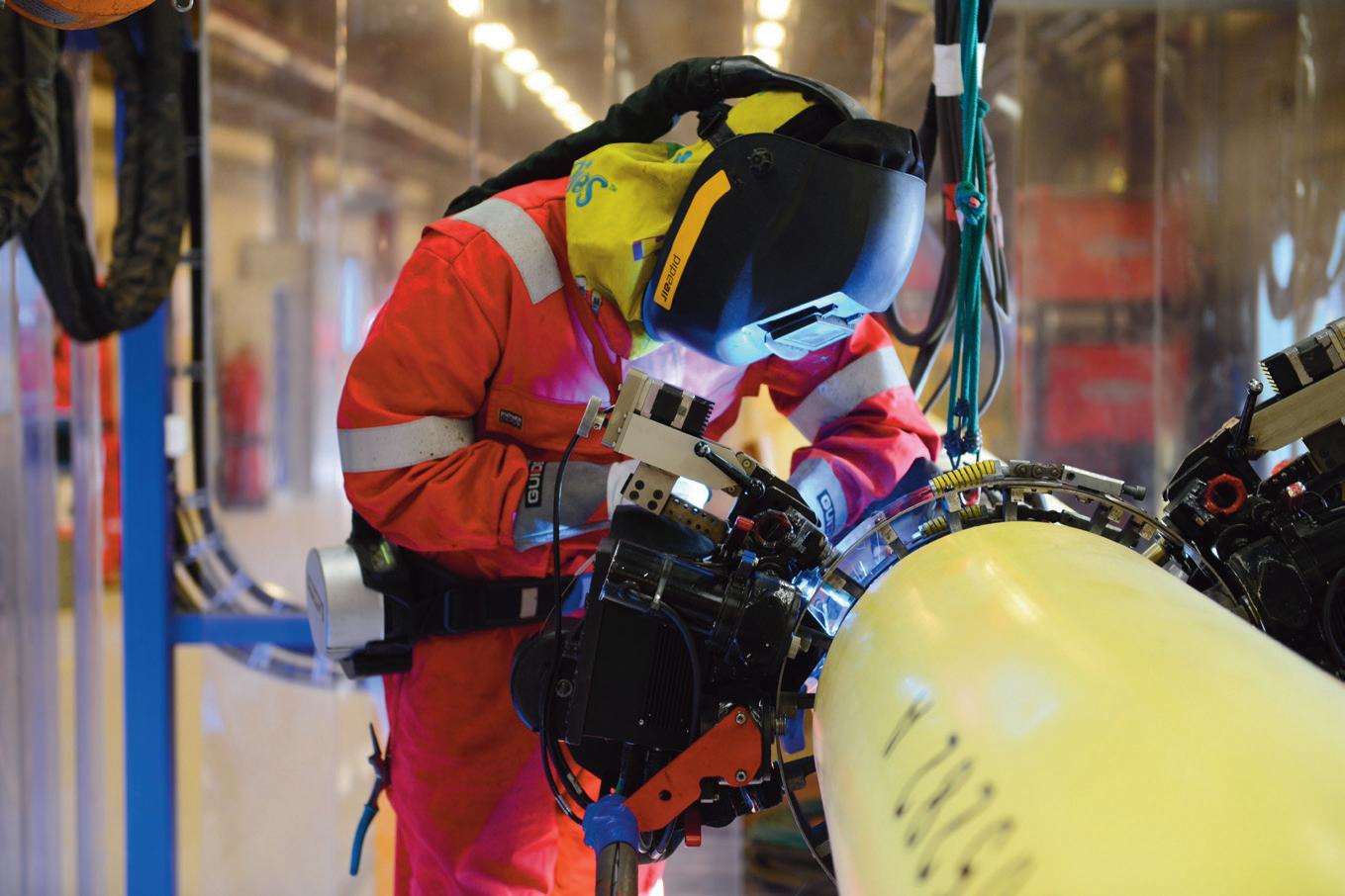
DECEMBER 2022 For over 30 years,
has been one of the leading companies specialising in
using composite technology. We offer our clients a complete integrated service; development, manufacturing, retail, and installation. From our head offices in Monaco, we operate worldwide, in any environment (onshore, offshore or subsea), thanks to our large qualified distribution network of over 60 partners. www.3xeng.com
33 CBP006075 49
03. Editor's
05. Pipeline news With updates from E.ON, DNV and ExxonMobil.
PAGE 08 13
CYBERSECURITY 08. Keep the ball rolling Chris Grove, Director of Cybersecurity Strategy, Nozomi Networks, USA, shares some advice for moving the cybersecurity ball forward, with the goal of being better positioned to accommodate changing regulations.
Chris Grove, Director of Cybersecurity Strategy, Nozomi Networks, USA, shares some advice for moving the cybersecurity ball forward, with the goal of being better positioned to accommodate changing regulations. than it’s ever been before. As demand surges, exasperate, and risks become realities, it’s more security secure, crucial to our survival. critical infrastructure; in some, they are even more security strategy. As governments attempt to tackle the burdening infrastructure operators with redundant or on minimum-level to operate safely and securely. For the bar for minimum physical, design, and operational Series recent update ‘C’, are focused on cybersecurity for the pipelines. Both had the best interests of public safety in mind when they were drafted. At the time of drafting, there were cases of overlap, contention, and industry/government back and forth. As we discover new data, collaborate on issues, and new risks emerge and old risks evolve, the recommended minimum for safe operations is updated, thereby ‘raising the bar’ on what the minimum is, in order to safely operate the regulated asset. There will also be multitude of applicable, interconnecting, and overlapping regulations, standards, and best practices that reside-between the aforementioned rules and directives. In some cases, they may even have of sustaining vast those that will be regulated rarely works out well; collaboration that pipeline operations can bring. As an example, attempting copy and paste type rule setting, challenging and ambitious into the equation, the impact from mistake can be larger than what many are willing to accept. At the time that many of today’s regulations were drafted, the physical world and cyberspace was quite different place. Common risks were low-level cyber criminals, or disorganised one-off saboteurs. But the changing landscape due to the Russian invasion of Ukraine has resulted in turning the internet into a hot warzone, with multiple threat actor groups, ranging from state-sponsored, to hacktivists, to quasi-state cybermilitia viciously and relentlessly attacking critical infrastructure around the world. Their goal to create mass destruction by any means necessary. Another facet is the energy war being waged, with pipelines front and centre. After the Colonial Pipeline incident, it’s clear, nation-state actors will commit the same types of attacks when the time comes. Defending the pipelines against cyberattack is more than just protecting profit, it’s fighting in the trenches in new frontier of war. Government regulators know this, and are working 8 9 OIL & GAS SECURES YOUR INSTALLATIONS IN ANY ENVIRONMENTS INNOVATIVE REPAIR SOLUTIONS FOR YOUR INSTALLATIONS www.3xeng.com HIGH PERFORMANCE COMPOSITE REPAIR SOLUTION FOR PIPE REINFORCEMENT REINFORCEKiT®4D WORLD PIPELINES DECEMBER 2022 ® Volume 22 Number 12 - December 2022 www.worldpipelines.com OFC_WP_December_2022.indd KEYNOTE: ENVIRONMENT 13. Embracing the measurement economy Pauline Morrice, Senior Communications Advisor, UK and Steve Kemp, Senior Director of Customer Success, Project Canary, USA, consider why the measurement economy is changing the methane emissions game. METERING AND MONITORING 20. Machine learning models Dr Yanfeng Liang, TÜV SÜD National Engineering Laboratory. 25. Unmanned: the future of monitoring? Richard Hjelmberg, UMS SKELDAR, Sweden. 28. Flow balancing Tommi
Engineering Analysis
33. No moving forward without it Rolf
Lie,
Williamson, Asia
PAGE 38 The energy industry is rapidly embracing the DNP3 protocol for fast and cybersecure pipeline monitoring, suggests Steve Hill, Emerson, USA. afe and efficient transmission of product via energy pipelines has become more important than ever due to the growing need to efficiently manage an evolving product mix that includes newer products, such as biofuels and renewable natural gas (RNG), along with petroleum-based products. Global trends and shifting public opinion have led pipeline operators to focus increasing effort on eliminating transmission delays and leaks, which can only be accomplished through careful monitoring of every mile of a pipeline. However, not every mile of every pipeline will have access to reliable communication backbone capable of delivering real-time data securely. To overcome these obstacles, field operations and operational technology (OT) teams are pursuing new combinations of software, technologies, and communication infrastructure to address the challenges of unreliable networks, while simultaneously improving cybersecurity across the entire pipeline. Distributed network protocol (DNP3) is at the heart of this shift, prompting forward-thinking organisations to include it as part of their future The importance of robust pipeline protocols To ensure safe, effective transmission of product across miles of pipeline, operators and maintenance personnel need constant and clear visibility into what happening in even the most remote locations. To enable this visibility, teams need communication infrastructure that ensures data provided reliably and delivered efficiently, while simultaneously minimising the risk of cyberattacks. One of the most common strategies teams rely upon to ensure data integrity is storing historical data in remote terminal units (RTUs). When everything operates as planned, RTUs gather data from the pipeline and transmit to supervisory control and data acquisition (SCADA) system, in real-time or near-real-time. However, 38 39
REMOTE
38. Communicating across networks Steve Hill, Emerson, USA.
Bergman, Manager of
and Taija Hämäläinen, Director of Butterfly Valves, Valmet, Finland. PIGGING
Gunnar
T.D.
Pacific.


Headline sponsor The forum for the pipeline community, exploring pipeline coatings, hydrogen transportation, new technology and markets Hear from the global supply chain, including: SECURE YOUR DISCOUNTED PLACE TODAY www.ami.ltd/event-pipeline-wp Thierry Kerzerho Integrity Engineer GRT Gaz Denis Melot Expert Non-Metallic Materials and Coatings TotalEnergies Michele Castano Senior Coating Engineer EniProgetti Haralampos Tsaprailis Coatings Specialist Enbridge Employee Services Canada Pipeline Coating 13-15 February 2023 | Vienna, Austria *Discount cannot be used in conjunction with other offers. Only available for new event attendees. Other speaking companies include: Charter Coating Services (2000), Dam Coating, The Sherwin-Williams Company, Norner, Cefracor, AkzoNobel Powder Coatings, Seal For Life, AMI, Axalta, Borealis and more! Also sponsored by: Supported by:
EDITOR’S COMMENT
CONTACT INFORMATION
MANAGING EDITOR
James Little james.little@palladianpublications.com
EDITORIAL ASSISTANT
Sara Simper sara.simper@palladianpublications.com
SALES DIRECTOR
Rod Hardy rod.hardy@palladianpublications.com
SALES MANAGER
Chris Lethbridge chris.lethbridge@palladianpublications.com
SALES EXECUTIVE
Daniel Farr daniel.farr@palladianpublications.com
PRODUCTION MANAGER
Calli Fabian calli.fabian@palladianpublications.com
EVENTS MANAGER
Louise Cameron louise.cameron@palladianpublications.com
DIGITAL EVENTS COORDINATOR Stirling Viljoen stirling.viljoen@palladianpublications.com

DIGITAL CONTENT ASSISTANT Merili Jurivete merili.jurivete@palladianpublications.com
DIGITAL ADMINISTRATOR Leah Jones leah.jones@palladianpublications.com
ADMINISTRATION MANAGER
Laura White laura.white@palladianpublications.com
Palladian Publications Ltd, 15 South Street, Farnham, Surrey, GU9 7QU, UK
Tel: +44 (0) 1252 718 999 Website: www.worldpipelines.com Email: enquiries@worldpipelines.com
Annual subscription £60 UK including postage/£75 overseas (postage airmail). Special two year discounted rate: £96 UK including postage/£120 overseas (postage airmail). Claims for non receipt of issues must be made within three months of publication of the issue or they will not be honoured without charge.
Applicable only to USA & Canada: World Pipelines (ISSN No: 1472-7390, USPS No: 020-988) is published monthly by Palladian Publications Ltd, GBR and distributed in the USA by Asendia USA, 17B S Middlesex Ave, Monroe NJ 08831. Periodicals postage paid New Brunswick, NJ and additional mailing offices. POSTMASTER: send address changes to World Pipelines, 701C Ashland Ave, Folcroft PA 19032
An editorial team reads each issue of a magazine many times over before it’s published: we check for inaccuracies, typos, breaks in flow and all sorts of things we hope to catch before the printer springs into action. This month, as every month, Editorial Assistant, Sara Simper made some pertinent notes in the margins of the paper proofs, and one note caught my eye: she wrote that a section from the Nozomi Networks article was an interesting point (and a good starting point for a column). So here I am, thinking about the quote, which goes: “Essentially, it’s the realisation that all great things will fail one day, eventually. It is therefore not entirely about the prevention of failures; sometimes we also need to plan on being resilient to failure.”
The context of the quote is designing cybersecurity for pipelines. The article explains that software companies tend to design network security in layers, with the understanding that each layer could eventually be compromised. They resist security breaches by building in the layers, but they make the network resilient to security breaches by making sure the system can withstand one of those layers failing. Read the article (p.8) to learn how Nozomi is leveraging a resiliency-based mindset to tackle pipeline cybersecurity, even in the face of changing regulations and an ever-changing threat reality.
It strikes me that resisting something means pushing back against it with all of your might: planning, strategising, shoring up defences. This is worthy work and a vital part of creating safe, efficient pipeline systems. However, being resilient means that even if the worst happens and a breach occurs, you have options: a plan B and a plan C, a way to re-route and regain control. So, within resilience we find being quick-thinking a good attribute, but also the ability to accept change. Starting on p.13, Kellas Midstream and Project Canary write about the measurement economy and how it is changing the business of methane emissions. The article addresses the problem of pipeline leaks and fugitive emissions, and explains how midstream operators need to look towards leak detection technologies that measure in real-time and utilise analytics. Continuous methane monitoring sensors are able to offer advanced monitoring and insight, to enable rapid interventions should a leak be found. This is resilience.
Throughout this issue of World Pipelines, there are many examples of the pursuit of resilience: TUV SUD National Engineering Labroratory describes optimising flowmeter data to make for better decision-making on flowmeter fault detection and diagnosis. Machine learning and data-driven models can be used to react to, as well as prevent, flowmeter failure. Valmet offers insight into improving process performance in demanding control valve applications: flow control can be made more resilient by simulation-driven development, and by building in versality to valve design. UMS Skeldar writes about using unmanned aircraft for preventative maintenance, which brings about resilience in terms of cost cutting (crew, fuel etc.) and also reducing risk. The very existence of pipeline isolation technology (T.D. Williamson, p.33) is resilience in action: TDW outlines a bespoke recovery tool in a case study that showcases technical excellence and flexibility on the job.
See also, Emerson on developing robust pipeline protocols for a changing pipeline product mix (p.38); Tracerco on the operational benefits of extending a pipeline’s life (p.45); and much more.
Sara and I look forward to building resilience with you all in 2023! Questions, comments and feature ideas always welcome at elizabeth.corner@worldpipelines.com
SENIOR EDITOR Elizabeth Corner elizabeth.corner@palladianpublications.com
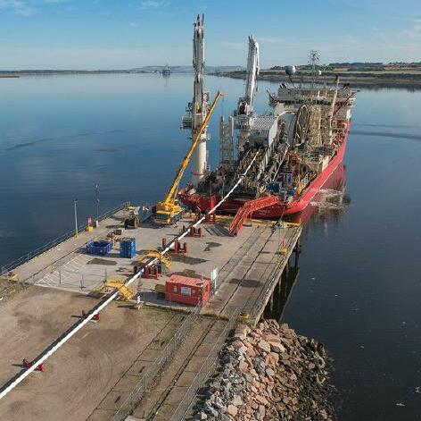
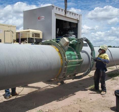
Pipeline Induction Heat (PIH) provide specialist field joint coating services at spool base locations, offshore pipe lay barges and onshore pipeline construction projects around the world, involving the use of stateof-the-art equipment and processes for the application of a wide range of field joint coating materials.
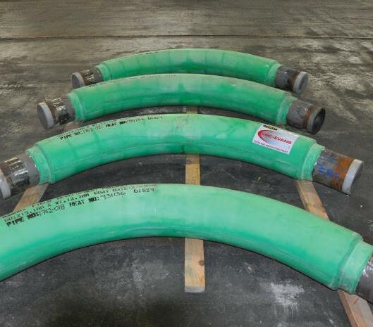

PIH also provide Custom Coating services for the application of the latest Thermal Insulation solutions (IMPP and IMPU) to bends and spools.


Field Joint Coating and Custom Coating Services
Innovation Integrity Offshore Onshore Spoolbase Custom Coating Pipeline Induction Heat Ltd, Burnley, UK Tel: +44 (0) 1282 415 323 Fax: +44 (0) 1282 415 326 E-mail: sales@pih.co.uk Web: www.pipelineinductionheat.com
Dedication
E.ON cuts value of its Nord Stream 1 stake
E.ON, Europe’s biggest operator of energy networks, on 9 November said it had almost fully cut the value of its stake in Nord Stream 1, reflecting damage to the pipeline that has made the asset inoperable and whose cause is yet to be determined.
E.ON, in its nine-month report, said the value of the 15.5% stake, which is sitting in its pension fund, was cut by another € 400 million (US$403 million) to € 0.1 billion, down from € 0.5 billion at the end of June.
“Among the reasons for this are greater uncertainty amid the current situation and, since 26 September, damage to both of Nord Stream 1’s pipelines whose cause is as yet unclarified,” the company said.
Nord Stream 1 and Nord Stream 2 were damaged in September, and the gas transport infrastructure has been a focal point in the wider row between the West and Moscow. NATO Secretary-General, Jens Stoltenberg has called the damage an act of sabotage.
News about the value adjustment came alongside E.ON’s results for the first nine months of 2022, which showed a 3% decrease in adjusted core profit (EBITDA) to € 6.1 billion. Adjusted net profit was also down 3% at € 2.1 billion.
The company still stuck to its 2022 outlook, expecting adjusted EBITDA of € 7.6 billion to € 7.8 billion and an adjusted net income of € 2.3 billion to € 2.5 billion.
Ukraine to raise Druzhba oil transit fee after Russian strikes
Bloomberg reports that Ukraine will raise transit fees for Russian oil through the Druzhba pipeline to eastern Europe next year, following Moscow’s attacks on the nation’s power supplies.
Ukrtransnafta JSC, the operator of Ukraine’s oil pipeline network, informed its Russian counterpart Transneft PJSC that “continued destruction of the Ukrainian energy infrastructure has led to a significant shortage of electricity, an increase in its costs, a shortage of fuel, spare parts,” according to a letter from the company seen by Bloomberg.
The cost of organising safe work conditions for its personnel and protecting its facilities has also increased, according to the letter, which was signed by Volodymyr Tsependa, General Director of Ukrtransnafta.
The company said it will raise tariffs for transporting
crude toward Hungary and Slovakia by € 2.10 to € 13.60/t (US$13.90/t) from 1 January 2023. The fee was also hiked in April, bringing the total increase on an annualised basis to 51%.
On 15 November, Russian crude flows to eastern Europe were halted for a day after a power station serving the pipeline in Ukraine was hit by artillery fire. That day, Russia launched around 100 rockets into Ukraine, according to the country’s air force in Kyiv.
Ukrainian President, Volodymyr Zelenskiy has urged his citizens to limit energy consumption, accusing Russia of trying to “kill” power and heating for millions at the onset of winter.
Russian state oil pipeline monopoly Transneft is reportedly reviewing Ukraine’s proposal to raise its oil transit fee.
DNV partners with energy companies on software for ammonia, hydrogen and CCUS
The energy transition depends on several technologies with potential hazardous characteristics, such as carbon capture and storage (CCS), and utilisation of hydrogen and ammonia. When deploying these solutions at a larger scale, safety is essential. DNV is working with energy companies to address this in three research projects.
DNV is leading three parallel joint industry projects (JIPs) to develop the existing KFX software, which simulates gas dispersion, fire and explosions, to increase safety in the deployment of energy transition solutions. The KFX computational fluid dynamics (CFD) software simulates what actually happens to liquids, vapour clouds and potential dry ice formation in the event of accidents. The simulations are used as the basis for design of installations and to mitigate consequences.
“DNV has in recent years been involved in CFD simulation software development projects. The JIPs for CCS, hydrogen and ammonia safety strengthen our commitment to the energy transition,” says Kenneth Vareide, CEO of Digital Solutions at DNV.
In the event of an accidental release, there are widely varying scenarios depending on the properties of the gases
or liquids involved.
The first JIP is a partnership between Equinor, TotalEnergies and DNV, and focuses on CO 2. The research concentrates on the consequences of accidental release, depending on surrounding environmental conditions such as terrain and wind, combined with dry-ice formation and its impact on dispersion.
The second JIP includes Equinor and DNV, focusing on hydrogen and the consequences of low storage temperatures, dispersion, fires and explosivity.
The third JIP, with Equinor, Vår Energi, Horisont Energi and DNV, is developing solutions for ammonia safety, analysing alternative strategies to mitigate consequences of toxicity.
“DNV is committed to close collaboration with customers in the areas of hydrogen safety, CO2, ammonia and LNG, enabling the accelerated energy transition journey,” says Trond Evanger, Head of Section of CFD Solutions at DNV.
KFX CFD software has been developed for more than 25 years by DNV in collaboration with Equinor, TotalEnergies, ConocoPhillips, Eni, Gassco, GRT GAZ and other energy companies, as well as the Research Council of Norway.
DECEMBER 2022 / World Pipelines 5
WORLD NEWS
CONTRACT NEWS
Pipeline Technique enters agreement with Subsea7
6 - 10 February 2023
Pipeline Pigging and Integrity Management Conference and Exhibition Houston, USA www.ppimconference.com
7 - 11 February 2023
PLCA Annual Convention Hawaii, USA www.plca.org/annual-convention-events
13 - 15 February 2023
Pipeline Coating 2023 Vienna, Austria www.ami-events.com
20 - 21 February 2023
Transportation Oil and Gas Congress 2023 Istanbul, Türkiye www.togc.events
20 - 25 February 2023
DCA Annual Convention 2023 Miami, USA www.dcaweb.org/page/Convention
19 - 23 March 2023
AMPP Annual Conference + Expo Denver, USA www.ace.ampp.org
27 - 29 March 2023
European Gas Conference 2023 Vienna, Austria www.energycouncil.com/event-events/ european-gas-conference
1 - 4 May 2023
Offshore Technology Conference 2023 Houston, USA 2023.otcnet.org
Pipeline Technique (PTL), provider of welding and coating solutions to the global onshore and offshore energy sectors, has entered into a long-term agreement with Subsea7 for the provision of welding and coating services.
Under the terms of the agreement, PTL will provide Subsea7 with access to a team of experienced specialists and cutting-edge equipment, building upon the pre-existing and long-standing relationship between the two companies.
PTL supports customers’ projects through the consistent and progressive delivery of global rigid pipeline systems, locally tailored solutions, automation and strategic supply chain partnerships.
PTL recently acquired the Oil and Gas division from Stanley Black & Decker, a major international pipeline services and equipment provider, bringing together two
CF Industries and ExxonMobil sign major deal on CCUS in Louisiana
CF Industries, a global manufacturer of hydrogen and nitrogen products, has entered into the largest-of-its-kind commercial agreement with ExxonMobil to capture and permanently store up to 2 million t of CO2 emissions annually from its manufacturing complex in Louisiana. Start-up for the project is scheduled for early 2025.
CF Industries is investing US$200 million to build a CO2 dehydration and compression unit at its Donaldsonville, Louisiana, facility to enable captured CO2 to be transported and stored. ExxonMobil will then transport and permanently store the captured CO2 in secure geologic storage it owns in Vermilion Parish.
As part of the project, ExxonMobil has signed an agreement with EnLink Midstream to use EnLink’s transportation network to deliver CO2 to permanent geologic storage. The 2 million t of emissions captured annually will be equivalent to replacing approximately 700 000 gasoline-powered cars with electric vehicles.
“EnLink has a system of over 4000 miles of pipeline already in the ground in Louisiana,” said Jesse Arenivas, CEO of EnLink. “Utilising this extensive network enables us to provide the most timely and cost-effective solution to CO2 transportation, with a significantly lower environmental impact. Because of this, EnLink is uniquely positioned to be the CO2 transportation provider of choice in Louisiana’s Mississippi River corridor.”
long-term suppliers of Subsea7 and further strengthening this collaboration agreement.
The acquisition of CRC-Evans, Pipeline Induction Heat (PIH), and Stanley Inspection (including MicroAlloying, part of Stanley Inspection) created a global leader in PTL, with expected revenues in excess of US$200 million.
Ben Mackay, COO for PTL, said: “By offering predictability, we can provide Subsea7 with a robust foundation for longterm planning and enhanced project performance. We look forward to contributing to more efficient operations benefitting both parties.”
PTL CEO, Frederic Castrec said: “PTL’s close working relationship with Subsea7 spans several years, and this collaboration agreement forms the basis for its long-term continuation.”
THE MIDSTREAM UPDATE
• Penspen announces launch of Energy Transition Consultancy
• Shell partners with Kongsberg Ferrotech
• Novarc to partner with Lincoln Electric
• AIS acquires subsea specialist CRP Subsea
• TC Energy reports strong 3Q22 results
• Natural gas imports from Canada provide winter reliability
Follow us on LinkedIn to read more about the articles linkedin.com/showcase/worldpipelines
6 World Pipelines / DECEMBER 2022
EVENTS DIARY
PROTECTIVE OUTERWRAPS SOIL-TO-AIR INTERFACE SYSTEMS BITUMEN & BUTYL TAPES PETROLATUM TAPE SYSTEMS PROTAL 7200™ SPRAY/ROLLER/BRUSH APPLIED LIQUID EPOXY COATING DENSO VISCOTAQ™ FOR CORROSION PREVENTION DENSO™ are leaders in corrosion prevention and sealing technology. With over 135 year’s service to industry, our mainline and field joint coating solutions offer reliable and cost effective protection for buried pipelines worldwide. United Kingdom, UAE & India USA & Canada Australia & New Zealand Republic of South Africa www.denso.net www.densona.com www.densoaustralia.com.au www.denso.co.za A MEMBER OF WINN & COALES INTERNATIONAL A range of viscoelastic tapes used for corrosion prevention on pipelines, field joints, fittings & valves. The unique, self-healing technology of Viscotaq offers asset owners outstanding, long-term protection against corrosion. > >
ipeline cybersecurity is more important now than it’s ever been before. As demand surges, the technology landscape morphs, the threats exasperate, and risks become realities, it’s more apparent than ever that keeping the backbone of energy security secure, is crucial to our survival.
In most developed nations, pipelines are considered critical infrastructure; in some, they are even more critical, being a key component in a national energy security strategy. As governments attempt to tackle the problem, they are faced with the challenge of not overburdening infrastructure operators with redundant or unnecessary regulations, while continuing to raise the bar on a minimum-level to operate safely and securely. For example, US government 49 CFR part 192 and 195 sets the bar for minimum physical, design, and operational safety characteristics for pipelines, but others, like the TSA SD02 Series recent update ‘C’, are focused on cybersecurity for the pipelines. Both had the best interests of public safety in mind when they were drafted. At the time of drafting, there were cases of overlap, contention, and industry/government back and forth. As we discover new data, collaborate on issues, and new risks emerge and old risks evolve, the recommended minimum for safe operations is updated, thereby ‘raising the bar’ on what the minimum is, in order to safely operate the regulated asset.
There will also be a multitude of applicable, interconnecting, and overlapping regulations, standards, and best practices that reside-between the aforementioned rules and directives. In some cases, they may even have competing requirements.

There’s no doubt that regulatory overhead adds to the complexities of sustaining vast pipeline operations. Creating regulations without input from those that will be regulated rarely works out well; collaboration and flexibility are crucial in order to accommodate the nuances that pipeline operations can bring. As an example, attempting to forklift electricity grid regulations over to pipelines, or other copy and paste type rule setting, is challenging and ambitious in general, but when industrial control systems are introduced into the equation, the impact from a mistake can be larger than what many are willing to accept.
At the time that many of today’s regulations were drafted, the physical world and cyberspace was quite a different place. Common risks were low-level cyber criminals, or disorganised one-off saboteurs. But the changing landscape due to the Russian invasion of Ukraine has resulted in turning the internet into a hot warzone, with multiple threat actor groups, ranging from state-sponsored, to hacktivists, to quasistate cyber-militia viciously and relentlessly attacking critical infrastructure around the world. Their goal is to create mass destruction by any means necessary. Another facet is the energy war being waged, with pipelines front and centre. After the Colonial Pipeline incident, it’s clear, nation-state actors will commit the same types of attacks when the time comes. Defending pipelines against cyberattack is more than just protecting profit, it’s fighting in the trenches in a new frontier of war. Government regulators know this, and are working
8
Chris Grove,
of Cybersecurity Strategy,
Networks, USA, shares some advice for moving the cybersecurity ball forward, with the goal of being better positioned to accommodate changing regulations.

9
Director
Nozomi
expeditiously to mitigate this risk, as quick as possible, with the best information on hand.
Based on the existing cyber threat level, the potential for a full-blown cyberwar, and the realisation that the next frontier of warfare could be our pipelines, we don’t want to find ourselves in the position of looking back, wishing we had done more, or questioning why our institutions didn’t act sooner. Regardless of where regulations land, the ball has to move forward. Most technologies and systems aren’t designed to withstand a directed, nation-state level attack. The Russian government has weaponised it’s cybercrime gangs, like TrickBot Gang, and are targeting critical infrastructure in Ukraine to further the advance of the war efforts. In this case their aim is destruction, not the pursuit of profit. To put that development in context, imagine if the motive behind the Colonial Pipeline attack was mass destruction and chaos rather than profit.
The challenges that face information technology (IT) systems are generally solved differently than the types of issues facing operational technology (OT) systems. If even those high-level differences are not accounted for when rulemaking, the result may not be the one we are working toward. Take for example password changes: in an IT system, it makes sense and is a good practice to change the password often. But, when it’s applied as a prescriptive regulation to follow, without consideration for the design of the system being regulated, particularly when it comes to industrial control systems, the resulting efforts required to become compliant can be a lot more labour-intensive and intrusive to operations than expected. To further that, pipeline operators have larger public safety and economic criticality than a typical manufacturer running a typical OT system, and the vast geography that pipeline operations could span requires a much larger effort to physically visit for a password change. Unfortunately, the next step could be for pipeline operators to find a way to reduce costs and simultaneously obtain compliance, which can lead to installing high-risk remote access to the assets, simply to execute a password change from the central office. Exposing risky assets by installing remote-access for the sole purpose of pursuing an IT-centric best practice, or checking a box in a regulatory checklist, is not the most cost-effective or recommended approach. Letting checkboxes and a changing regulatory landscape steer the direction of an organisations risk management can drive up operational costs, as well as make compliance difficult to manage.
Good design, great operations
Compliance to best practices and regulations should be a byproduct of good design and great operations. This can be particularly true when it comes to cybersecurity. In the cybersecurity trade, we generally design security using a layered approach. This is primarily driven by the notion that eventually, one day, the attacker will bypass the security, so we need another layer of security on top of another layer, upon layer, like an onion. Essentially, it’s the realisation that all great things will fail one day, eventually. It is therefore not entirely about the prevention of failures; sometimes we also need to plan on being resilient to failure.
Resistance is about building and managing those security layers, but resilience is being able to withstand a failure of those layers as a whole, with minimal impact to operations or safety. For example, although we have many design specifications for the piping used in the transport of products, we also have various consequence reduction mechanisms in place for unplanned incidents (like damage from an earthquake, farm equipment, etc.), even though that may have complied with those specifications or regulations.
When an incident happens, a resistance mindset would result in a shutoff valve being installed to stop operations, halting the flow, in the event of failure in all of the layers. A resiliency mindset would be to install a way to re-route the product to ensure continued operations during an incident.
So how do we leverage a resiliency-based mindset when tackling pipeline cybersecurity, in the midst of changing federal regulations, while keeping modern cyber threat adversaries in mind?
First, we plan for static findings and facts to eventually fail and expect subsequent changes to happen. Today, we can say that using ‘X method’ against ‘adversary Y’ is a valid approach, but by the time the ink dries, ‘adversary Y’ has evolved. Therefore, embracing recommendations as a prescription makes adapting to change harder. If operators need a prescriptive approach, there are many that exist, such as ISA 62443. Instead, aim to have great cybersecurity, overall, which as a natural consequence will be agile enough to effortlessly adapt to change. Having a solid foundation of tools and technologies, based on some well-known tenants of cybersecurity can go a long way in obtaining easy compliance while raising the cybersecurity posture of pipeline operations. If one spends enough time studying many of the common cybersecurity best practices, guidelines, and regulations, some common themes start to emerge. Many are expecting some basics, some push for more advanced capabilities; but they all rely on having intimate knowledge of the assets within the environment, combined with monitoring for threats, and having a measurable way to track, report, and reduce risk.
Moving the ball forward
With all of this in mind, here’s some advice for moving the cybersecurity ball forward, with the goal of being better positioned to accommodate changing regulations.
) Develop a comprehensive asset inventory of everything that’s critical, connected to anything that’s critical, or connected to anything that’s connected to anything that’s critical. In other words, expand your vision and scope to include non-traditional technologies as assets, they’ll probably be the first to get hacked if you don’t. Make sure you know everything about the asset, the make, model, product number, serial numbers, who put the last configuration on it, who is interacting with it, for what purpose, how, and what’s considered ‘normal’ for that asset. Consider what operations would look like if that asset were impacted or unavailable.
) Monitor the asset for changes to anything, in particular, the firmware, running code, configuration settings, and
10 World Pipelines / DECEMBER 2022


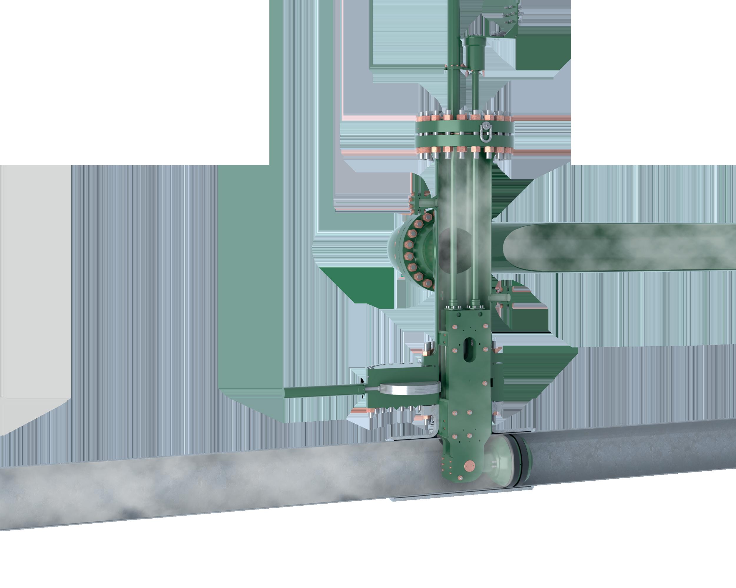


The BISEP® with extensive track record provides industry first double block and bleed isolation while maintaining production. Hydraulically activated dual seals provide fully monitored leak-tight isolation, every time, any pressure. ZERO-ENERGY ZONE SINGLE HOT TAP POINT DUAL Leak-Tight Seals double block & bleed isolation PRODUCTION MAINTAINED BISEP® Hot Tapping & Plugging ISOLATED PIPELINE
administrative-level controls like stop/start, Go Online, key positions, remote connections, etc.
) Monitor the network at all levels. At a generic high-level network, signature matching can be used to identify known attacks. A layer deeper, industrial control system protocols can be inspected for signs of reconnaissance activity like parameter scanning or requesting non-existent variables. Another layer deeper into the protocols, the actual ICS payloads can be monitored for anomalous values being set, or values being set at anomalous frequencies. Leveraging anomaly detection technologies to monitor the network will identify novel attacks that don’t yet have signatures.
) Develop people and processes on the receiving end of the monitoring, track their progress, and operationalise the security and set goals for improvement.
) Have a strategy for tracking and reducing risk, and hardening the assets. This includes knowing where the vulnerabilities are, having a plan to remediate them, and an active compensating control if they can’t be patched (as is common in industrial control systems).
) Develop and test incident response playbooks, ensuring the staff is able to respond when an event happens. Having an up-to-date communications plan with multiple
) Ensure there are multiple levels or backups of data and systems, but also that there is a restoration procedure that includes restoring operations, not just restoring data or a system.
) Execute tabletop exercises to test resilience to ransomware outbreaks, nation-state attacks, and other advanced threat actors.
) Engage with your partners. When under attack, sometimes your vendors and partners can make a huge difference in time to recovery. Find ways to enable and empower them before an event happens. It could range from working with cloud technologies, to safely working with external partners, to looping them into the playbooks and communications plans.
Summary
If we’re not planning on failures, we’re failing to plan. By having deep visibility and detailed knowledge of assets, and multiple layers of monitoring, we’re anticipating a failure in a security layer, like a firewall, virus protection, or other resistance technologies. By building a security programme driven by operational resiliency, when an incident or event happens, regulations change, or directives are written, organisations are better equipped for agility and lower recovery costs. Whether the task at hand is a nation-state attacker, a ransomware group, or new rules to follow, having complete visibility into
visit www.iploca.com to find out more
IPLOCA - supporting the reduction of carbon footprints in the pipeline industry
or midstream oil and gas companies, leaks and fugitive emissions from gas pipelines have long been a scourge. They are a source of wasted product and revenue loss, they pose safety risks, and cause damage to the environment that can adversely affect company finances through hefty fines or compensation.

Only now is the extent of the damage caused by methane leaks from pipelines being understood. Research from the Laboratory of Climate and Environmental Sciences found that during 2019 and 2020, over 1800 large bursts of methane occurred, often releasing many tons of methane each hour. It’s estimated that these large releases of methane are responsible for 8 12% of global methane emissions from oil and gas infrastructure.
Finding a solution that seals this problem for midstream operators might not just be a logical next step, but soon a mandatory one. In the US, the Pipeline and Hazardous Materials Safety Administration (PHMSA) is preparing to issue proposed standards that will require operators to use commercially available advanced leak detection technology to detect and fix leaks, and other countries are likely to follow.
This is not only the right thing to do both for the environment and companies’ bottom line, but an easier thing to do now than even a few years ago. Modern technology advancements have resulted in a step change occurring in leak detection methods. Legacy methods were imprecise, time consuming, outdated, impractical and resource intensive, such as inspecting pipeline right of ways for visual signs of disturbance, walking lines with portable gas sensors, and monitoring for changes in pipeline pressure.
Pauline Morrice, Senior Communications Advisor, UK and Steve Kemp, Senior Director of Customer Success, Project Canary, USA, consider why the measurement economy is changing the methane emissions game.
13
Today’s marketplace is embracing the measurement economy – measuring environmental performance and identifying verifiable climate attributes using real-time data and analytics – that is now being used by companies to minimise waste, cut costs, reach climate targets, and protect the public.
Harnessing climate-tech with the measurement economy
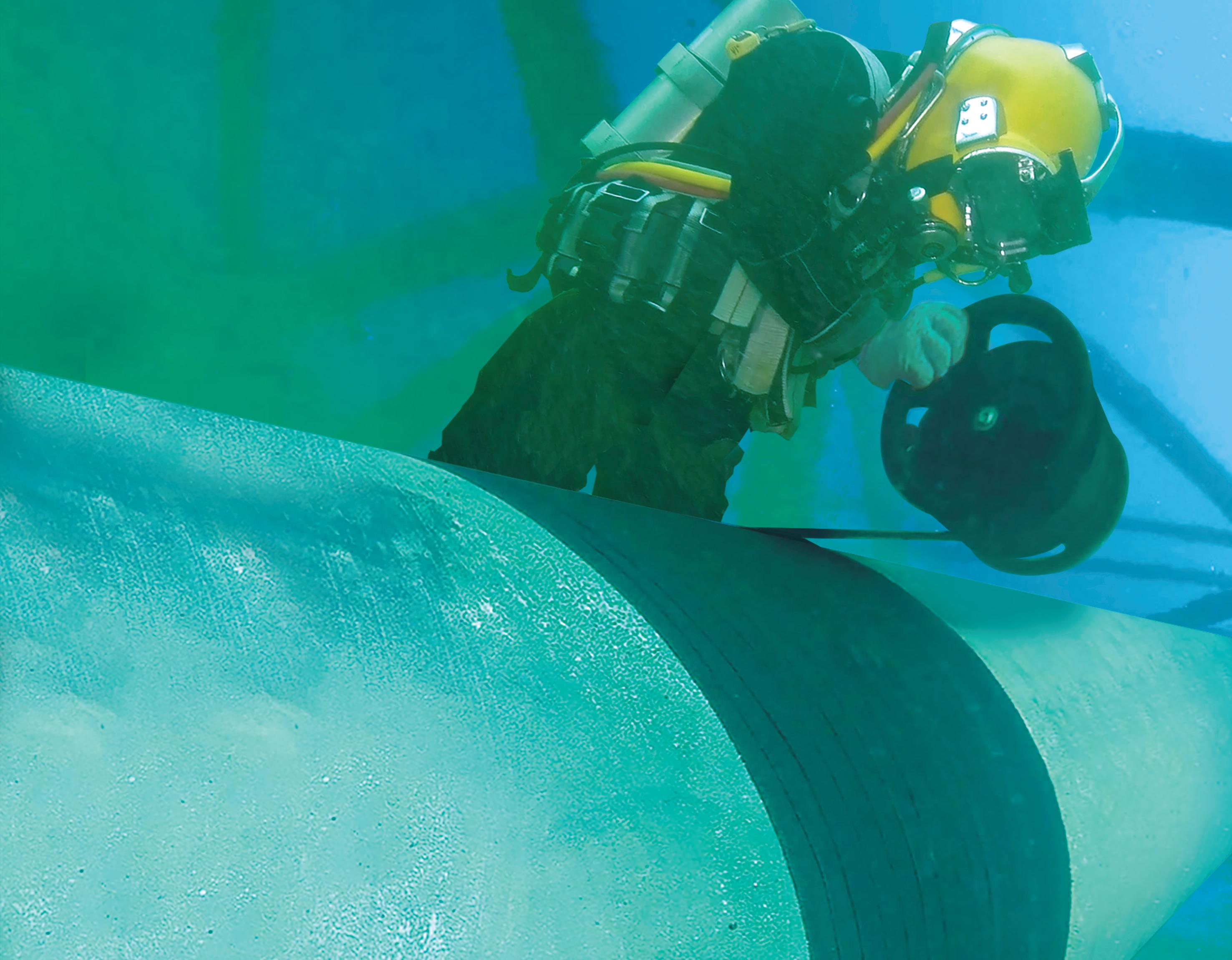
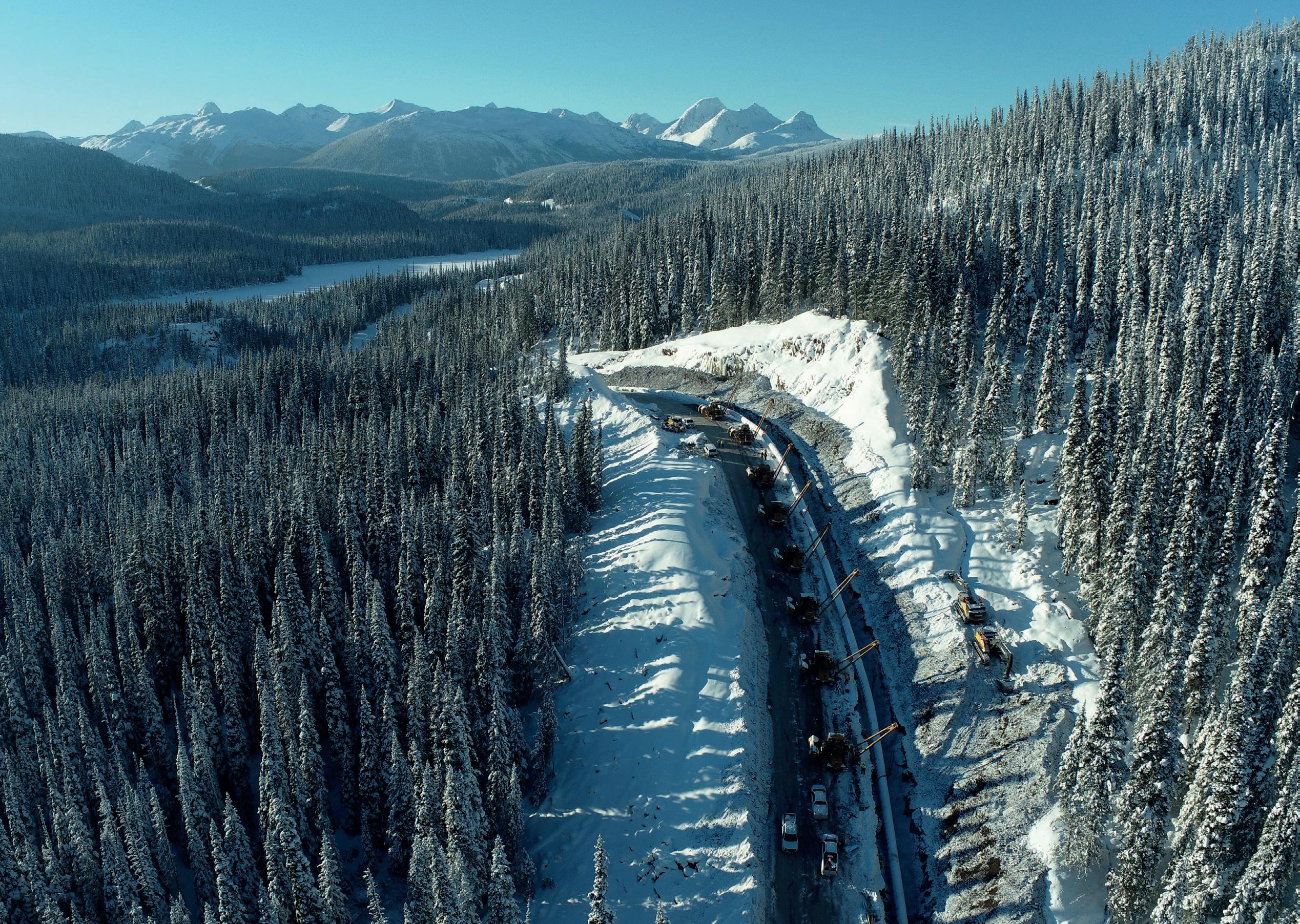
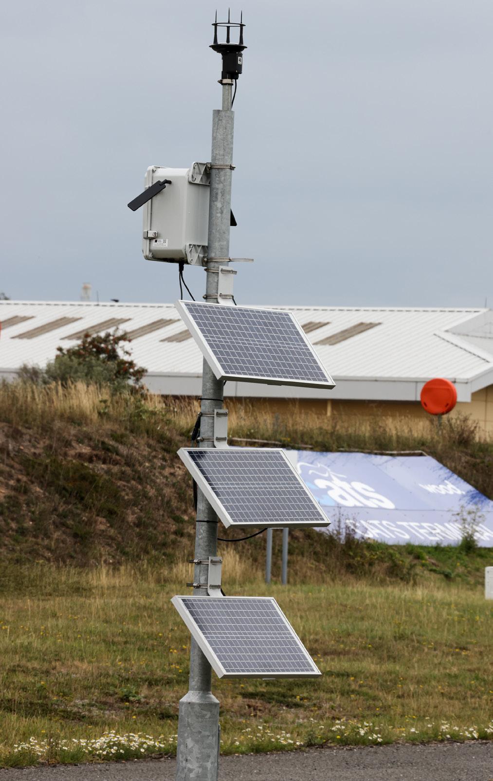
Last winter, Kellas Midstream entered a partnership with Project Canary®, a US-based climate and emissions data firm, to install 12 high-fidelity continuous methane monitoring sensors at its Teesside Central Area Transmission System (CATS) terminal in northeast England. The sensor array relies on technology that can detect methane down to <0.1 g/sec.
and report this data to a cloud-based dashboard every 60 sec. for advanced continuous monitoring and insights. This level of fidelity is unparalleled and consequently provides precise accuracy and granularity of data in real-time that has never been seen before in molecule tracking. The ‘measurement economy’ means that technology is advancing; and as the technology advances, so has Kellas Midstream’s ability to advance methane emission detection, monitoring, and measurement to become even more accurate than its competitors and take immediate action on any methane leaks. This capability to detect and make rapid interventions on any leaks ensures that gas moving through its pipelines is transported with the highest level of reliably accurate accounting of methane and now, Verified Climate AttributesTM, while helping to fortify its standing as an ESG leader in the sector. Ultimately, utilisation of this pioneering technology is raising the bar for midstream operators, and sending a message to the market that the new gold standard is now measurement of emission profiles minute by minute for immediate action. Quarterly or monthly emission profiles are not an assessment of methane leaks but merely a guess that in many cases can be off by up to 40%, which is sure to catch the eye of shareholders and environmental groups.
Oil and gas companies operate in a fast-changing landscape, and companies that can identify emerging legislation that is waiting on the horizon hold a competitive advantage over their competitors. In the UK, the country’s ‘Net Zero Strategy: Build Back Greener’ indicates that midstream operators are expected to minimise pipeline gas leakage and associated emissions. This means that as the UK enacts further regulatory and legislative policies to reduce its emissions in its push to reach its climate commitments under the Paris Agreement, forward-looking companies such as Kellas that have stayed ahead of the curve have future-proofed themselves against any potential disruptive emerging legislation.
Today, companies have a duty to be good neighbours to the communities they operate in, and for companies in heavy-emitting sectors such as oil and gas, this responsibility is even more pertinent. Methane leaks are not only a potent source of climate pollution, but they are also a health and safety hazard, and nuisance to nearby communities. Although rare, explosions that are dangerous to both people and property can result from gas leaks. Likewise, leaking methane can create a foul odour and harm nearby vegetation. Kellas has long demonstrated a commitment to being socially responsible in the communities it operates in and, by prioritising advanced leak detection through its partnership with
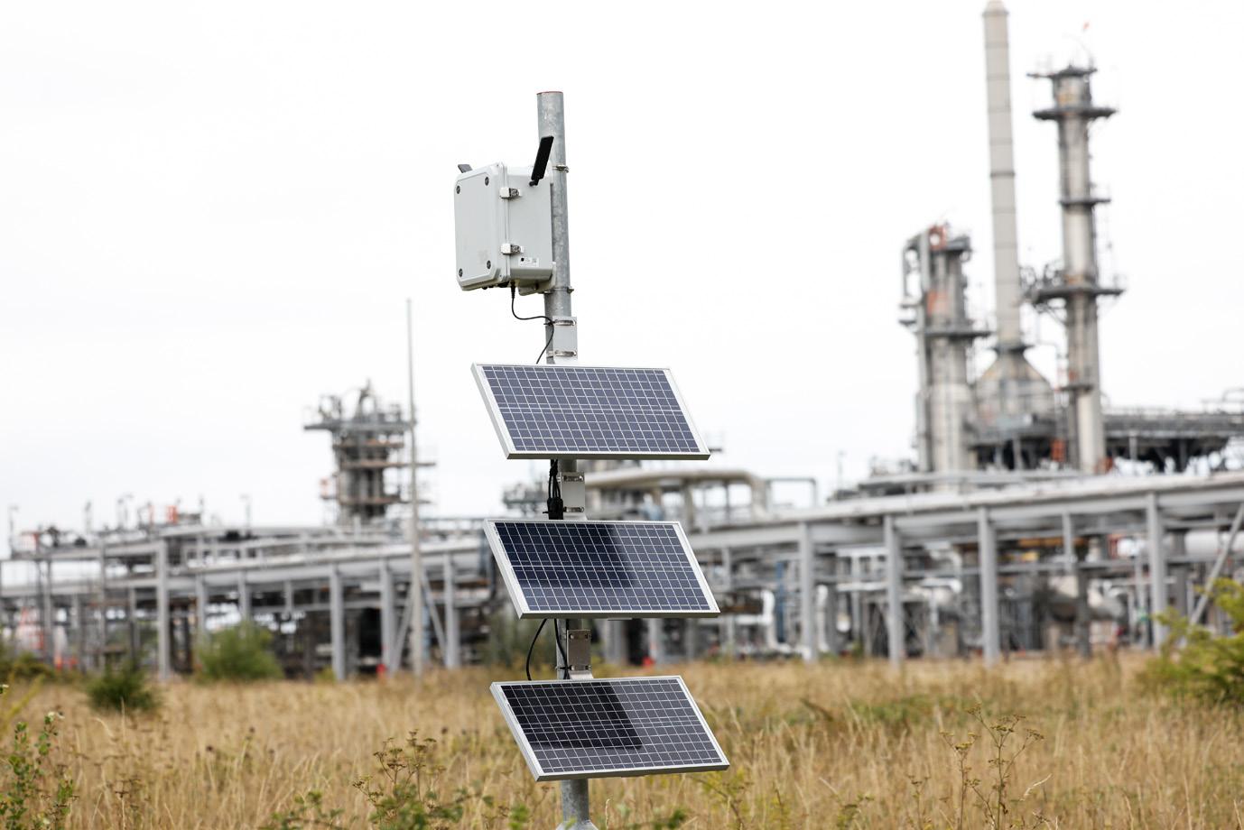
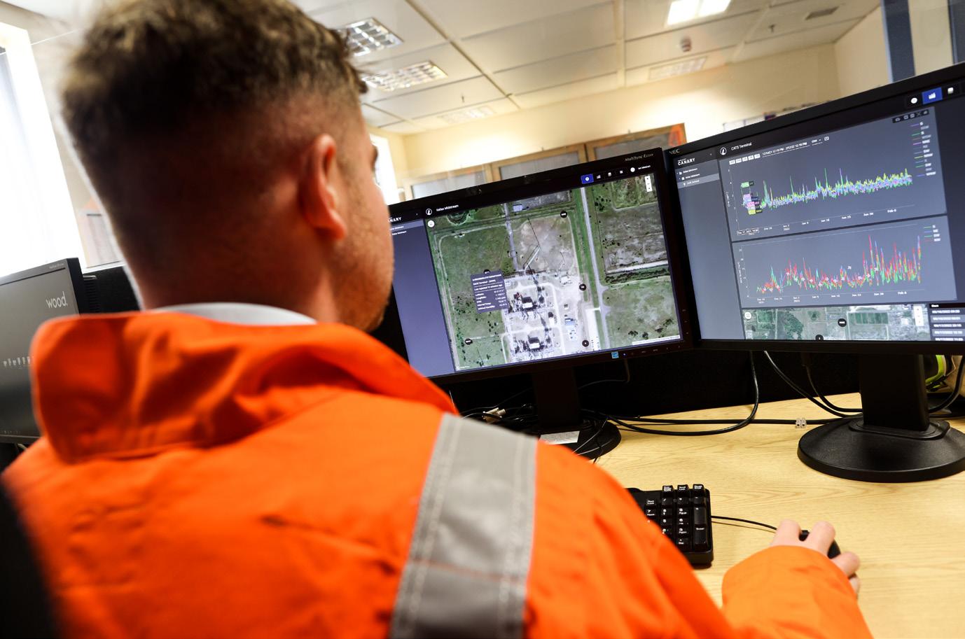
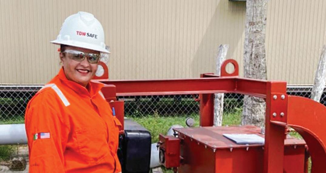
Figure 2. A Kellas Midstream employee demonstrating continuous emissions monitoring in real-time.
14 World Pipelines / DECEMBER 2022
Figure 1. Kellas Midstream installs Project Canary continuous emissions monitoring at Teesside CATS Terminal.
Project Canary, Kellas has reaffirmed its dedication to being a good neighbour. Additionally, by putting environmental stewardship first, Kellas has protected its strong relationship with the community in Teesside while also leading the way to a lower-carbon future.
Indeed, much has been made about the rapid uptake of responsible, low emission production in the upstream natural gas market, with estimates projecting that supply of producer-certified responsibly sourced gas (RSG) will soar from 8.7 billion ft3/d last year to surpass 20 billion ft3/d by the end of the 2022. But as the RSG market continues its tremendous growth with sustainability top of mind in the business arena, and ESG continuing to gain prominence in financial markets, there will be more and more value placed on low emission transportation of natural gas. This means midstream companies have an opportunity knocking on their door to seize this growing market by demonstrating their commitment to environmental stewardship with auditable third-party data.
Top of the agenda: managing methane emissions
There’s no denying it, the oil and gas industry has a methane problem. The sector is responsible for 82 million t, which
is roughly 15% of global methane emissions. And given that methane is over 80 times more potent than carbon dioxide, this is a problem we cannot afford to run away from.
But there is no need for the oil and gas sector to run away from this issue or bury its head in the sand. We have the tools and technology available to measure and manage methane leaks right now, and an increasing number of companies in the sector are realising this, as witnessed by RSG’s phenomenal growth.
It’s not too much of a stretch either to acknowledge that oil and gas companies’ long-term viability depends on addressing methane leaks. Last year, more than 100 countries signed the Global Methane Pledge at COP26, promising to reduce methane emissions by 30% by 2030, compared with 2020 levels, with the initiative emphasising making cuts by tackling methane leaking from oil and gas wells.
While net-zero by 2050 is the final destination, natural gas can serve as a ‘bridge fuel’ to transport us along the journey in the energy transition if we can guarantee that its production, gathering, processing, and transmission have been carried out with the highest level of sustainability standards. Indeed, signs point to a day in the not-too-distant future where certified natural gas is the industry standard.
Natural gas companies will continue to play a crucial role in the energy mix for decades to come, but only ones that place value on sustainability are likely to thrive long-term, considering that a generation of millennials and Gen-Z have turned their back on fossil fuels. With oil and gas companies experiencing a cash windfall from record oil prices, the time is right to invest some of that free cash flow into a more future-looking business model that allocates greater importance to ESG while reducing exposure to climate risk.
Ultimately, it is gas buyers that establish the standards. But as pressure mounts on utilities to prove their ESG credentials, midstream operators can improve the attractiveness of their product by demonstrating their ability to transport gas safely with the highest environmental standards used. Project Canary’s continuous methane monitoring sensors provide the data that allows ESG-leading midstream operators such as Kellas to deliver credentialed gas to buyers and validate their commitment to sustainability.
Governments have shown that they are not afraid to block energy deals if there are concerns around the environmental impact. In 2020, the French government stepped in to annul a US$7 billion deal between NextDecade and French utility Engie over concerns regarding methane emissions and other environmental impacts. However, following NextDecade’s decision to source 100% certified RSG for its planned Rio Grande Texas LNG export facility, Engie secured a 15 year contract.
Certainly, pressure is mounting from politicians, regulators, the public and investors for oil and gas companies to better manage methane leaks. Pakistan’s devastating floods this summer show that the consequences of failing to act on climate change can have catastrophic consequences. Advances in continuous monitoring technology means RSG has the ability to be the cleanest carbon on the planet, and tackle natural gas’ brand problem. The oil and gas sector has the tools at its disposal to be part of the solution in solving the climate conundrum by curbing methane emissions, and with strong balance sheets now the onus is on companies to demonstrate that they have the will.
16 World Pipelines / DECEMBER 2022
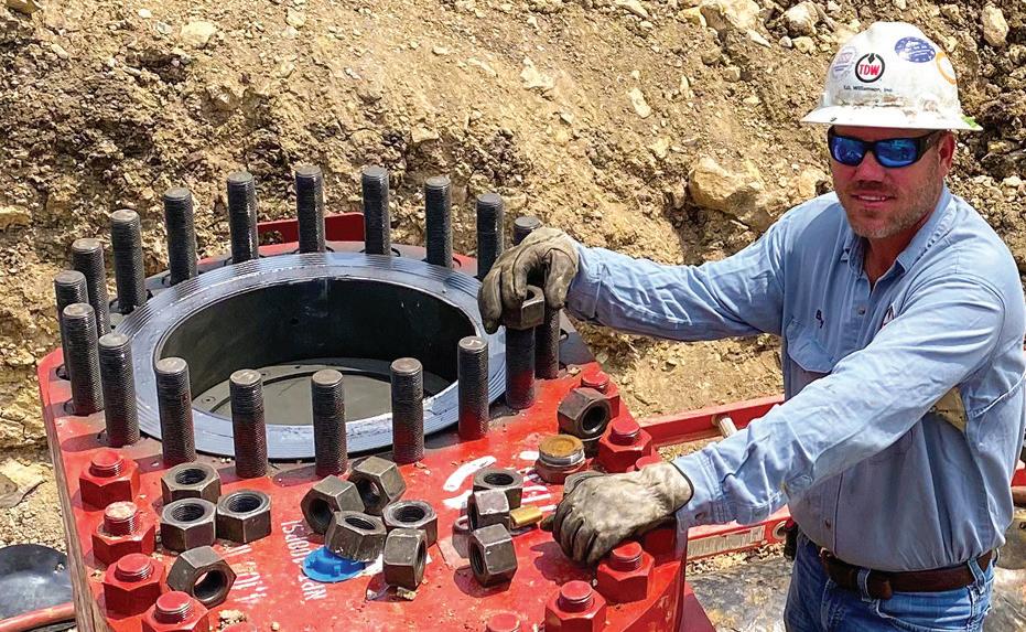
Figure 3. Kellas Midstream installs Project Canary’s sensors at multiple points throughout the terminal to precisely detect, monitor, and measure methane emissions in real-time.
IT IS MY ENDURING PLEDGE
to always deliver on my commitments, never underestimating the critical role that pipelines play as energy lifelines in fueling everyday life and unforgettable experiences.
It is who I am. I am a pipeliner.
We are pipeliners too.
Keeping product in the pipe is a big job that’s critical to protecting the environment, requiring specific expertise and technology to ensure success.
TDW brings industry-leading application engineering teams, innovative solutions and world-class technicians to help you deliver on your goals. We remain committed to supporting you and the industry in moving toward a more sustainable energy future.
The world counts on you. You can count on us.
For the life of your pipeline.
tdwilliamson.com
©2022 T.D. Williamson

20
Every day, massive volumes of data are created across a variety of industries.

Without the use of proper advanced modelling techniques such as machine learning (ML) models, however, the value and benefits from data cannot be extracted. This includes information such as the condition of instruments, fault detection, and diagnosis. Future performance forecasting can also be obtained, which will ultimately minimise unexpected downtime and provide an early warning when meters are approaching the end of their remaining useful life. As a result, it has become increasingly important to utilise predictive models and ML algorithms to unlock this valuable information and obtain new insights.
TÜV SÜD National Engineering Laboratory’s data acquisition systems have logged and archived 20 years’ worth of data, detailing various flowmeters’ performance, test facility configuration and operating conditions. Multiple research projects have been conducted, with the use of ML models and advanced modelling techniques showing that, despite operating under the same conditions, the performance of flowmeters belonging to the same technology
subgroup (e.g., Coriolis, electromagnetic, ultrasonic) can vary.
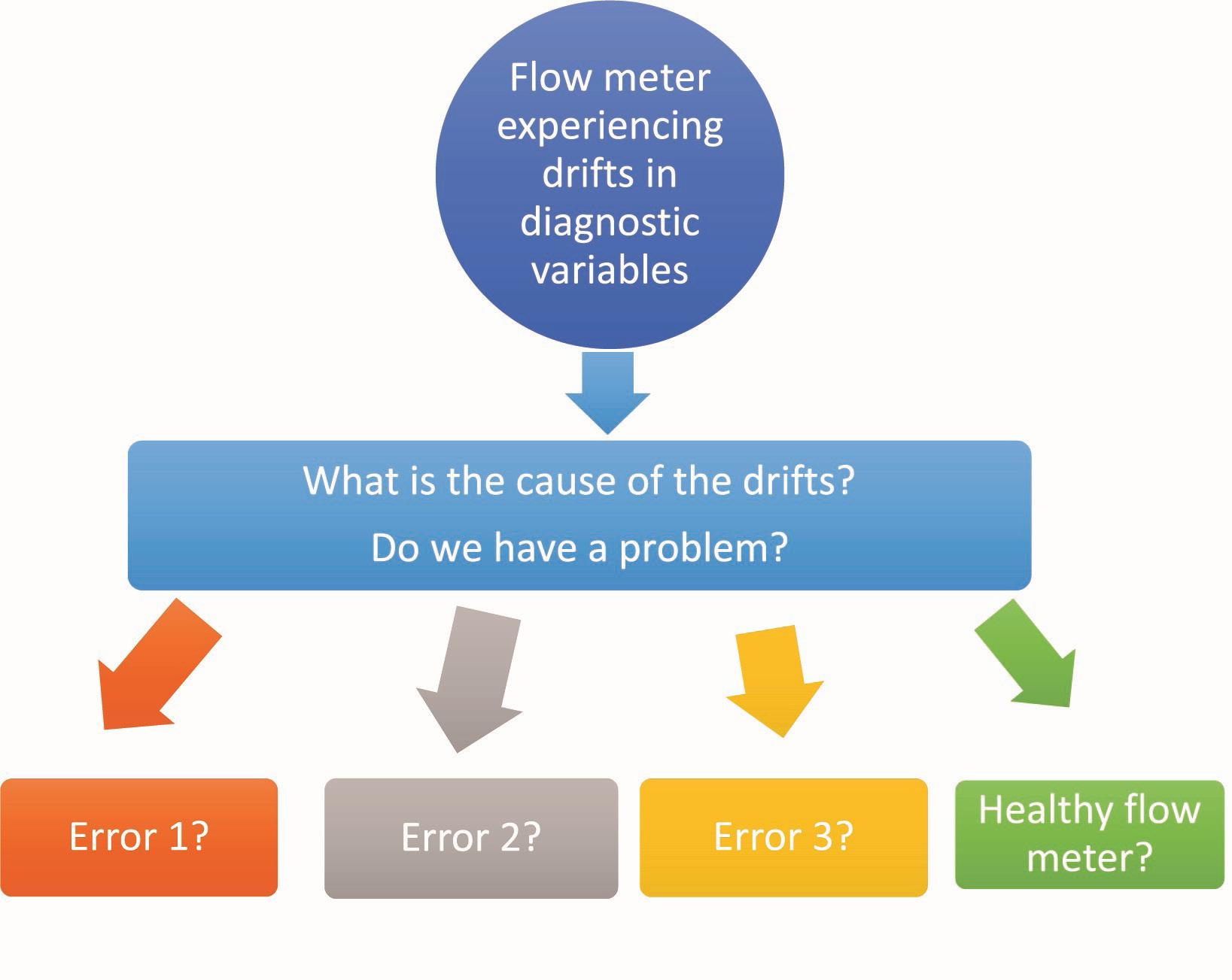
This is mostly due to differences in build and manufacturing materials, making it difficult to pinpoint the causes of sub-optimal performance. The performance of flowmeters is also dependent on operating conditions such as flow profile and pipe configuration. Typically, when a flowmeter is exposed to undesirable conditions, these are manifested as drifts from baseline values in multiple variables, thus giving the false impression that the error responsible for the drifts can be easily identified. Although drifts in variables can be an indication of potential underlying problems, our studies found that there is an inherent challenge in being able to distinguish and pinpoint the exact root cause of drifts in variables. In many examples it was found that different errors could induce the same drift patterns in the same variables. This challenge is described in Figure 1.
Such ambiguity and uncertainty in the fault diagnosis process could result in more time and effort performing additional inspections to pinpoint the exact root cause of drift. With the use of ML models and the appropriate datasets,
Dr Yanfeng Liang, TÜV SÜD National Engineering Laboratory, explores optimising flowmeter data for operational and strategic decision-making.
21
the challenge described in Figure 1 can be overcome and consequently improve end users’ fault detection and diagnosis process.
Experiments
To offer insight into the reasons for sub-optimal performance, we conducted experiments on meters with different sizes within two technology subgroups, where they were deliberately set up differently and exposed to various conditions and disturbances. A comparison on the performance of meters under each operating condition was made to determine which meter performed the best under a particular set up.
Our study revisited the historical data gathered from Meter Category A (Meter A) and Meter Category B (Meter B), which had been intentionally set up with different configurations, as a means of investigating the effect of each configuration on the performance of flowmeters. Simple plots were initially produced when the experiment was first conducted to compare the performance of these meters. From the basic ‘observational’ diagnostic assessments presented in previous research, it was apparent that the meters behaved differently depending on the configurations they were operated in. However, no further analysis was conducted on the data, and therefore only a limited insight was obtained.
Comparing data
Based on the simple plots produced initially, it was challenging to interpret the degree of impact when
changing operating conditions, as multiple results were obtained under various conditions. To deepen our understanding of the collected data, and to better visualise the impact of different setups on the performance of each meter, our new study revisited the data, whereby a series of statistical visualisation tools and advanced data-driven models were used to extract new insights. ML models were also built to detect the presence of a specific faulty condition within the system, where, if left undetected, it would have had a significant impact on the accuracy and reliability of the measurement outputs. These advanced modelling techniques allowed for more comprehensive insights to be extracted from the data, and provided a more conclusive representation of the performance of each meter.
When working with data that contains results from multiple factors, it is sometimes difficult to interpret and extract the most crucial findings. Therefore, having a good visualisation tool can aid end users to quickly identify similarities and differences in varying factors on the performance of flowmeters.
In this study, we used two different visualisation tools – box plots and interaction plots. A box plot is good for visualising and comparing the distribution of data under different setups, as well as displaying the critical statistical properties in data, such as the minimum, maximum, lower quartile, upper quartile, and the median values of the data. Any outliers (which could be an indication of potential underlying anomalies) are also illustrated in a box plot. While an interaction plot provides less information than a box plot, it does have the inherent advantage of allowing end users to quickly compare the effect of changing one factor on the overall performance of flowmeters by focusing on the mean value of the data. In other words, the interaction plot focuses on the degree of change when exposed to a different factor.
From these plots, it was found that Meter A outperformed Meter B by showing the least degree of drift from the baseline value measured by the percentage error in volume flow. It was also observed that the full-bore Meter A and Meter B that were studied had a similar drift pattern when changing from one operating condition to another. The effects of changing
22 World Pipelines / DECEMBER 2022
Figure 1. The challenge of determining the cause of drifts in diagnostic variables.
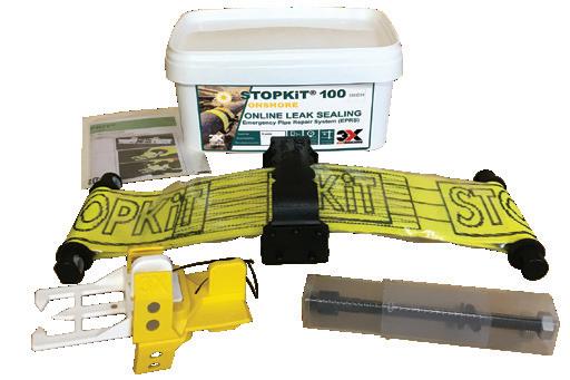


READY-TO-USE (EPRS) ONSHORE /OFFSHORE OIL & GAS
pipeline configurations and having a disturbance in the system were more predominant in full-bore meters.


Acheiving high prediction accuracy


The presence of a faulty condition will have a negative impact on the reliability and accuracy of outputs from flowmeters. Therefore, having the ability to detect such disturbance will ensure any issues are rectified promptly, and minimise the risk of errors propagating and affecting other related measurement outputs. Consequently, seven ML models under three scenarios were built and trained, where a mixture of data coming from different meters was used to detect a specific problem within the system, based entirely on the underlying patterns and trends in data.
In our previous studies, ML models were typically trained and validated using data generated from a single flowmeter. Although the models usually performed well with high prediction accuracy, it was challenging to apply the trained models to other meters because they were trained on variables that were unique to a particular flowmeter. In other words, the training sample space was restricted. As the meter diagnostic data was not logged during the original experiments, it provided an opportunity to explore the potential of building a more generic model that is trained based on a wider sample space involving data coming from multiple meter types.
Despite having no diagnostic data available, high prediction accuracy (97 - 99 %) and high sensitivity rates (0.96 - 1), accompanied with low false positive rates (0 - 0.07), were still obtained by successfully detecting when a set of data was gathered under normal operating conditions vs the faulty conditions. These results highlight the potential of making better use of data coming from different meters to expand the sample space to allow for a more generalised model to be trained and built, which would be capable of predicting specific operating conditions.
Conclusion
From the results and insights obtained from revisiting the historical data, it is evident that data-driven models and advanced modelling techniques have demonstrated the capability to help end users better understand a large amount of digital data output by flowmeters, as well as having the ability to detect the presence of undesirable operating conditions. This will improve end users’ fault detection and diagnosis process, and ensure any underlying problems are rectified promptly.
Certain data can be expensive to collect (for example, erosive flow data) but a reliable ML model often requires a large sample data for it to capture all hidden patterns and correlations in multiple variables. However, it is sometimes not cost-effective to collect a large amount of expensive data for the sole purpose of training a model. Therefore, if a model can be trained using a variety of data from different sources, it would maximise the potential value in the data, as well as make better use of smaller batches of expensive data from different sources. This would prevent smaller batches of expensive data from being wasted due to their unsuitability in training a ML model because of their small sample sizes, if used independently.
It seems that a common requirement from end users is ‘plug and play’. However, this is extremely challenging as models are typically bespoke to specific customer requirements/devices. By having generalisable models, we can offer faster deployment and enable automation with less requirement for fine tuning to specific meter type/manufacturer/model numbers, as well as improving the fault diagnosis process, enabling condition-based monitoring, and minimising any unexpected downtime. Future research within TÜV SÜD National Engineering Laboratory will continue to explore the potential and capability of generalising data-driven models to be applied in wider applications.
OUR BALL VALVES GO BEYOND THIS DISPLAY AND YOUR EXPECTATIONS! www.boehmer.de OIL, GAS, HYDROGEN, DISTRICT ENERGY & VARIOUS APPLICATIONS 1/8’’ - 56 ‘‘ CLASS 2500 AND HIGHER
he demand for oil and gas is extremely high across the world, at present mainly due to the war between the Ukraine and Russia. As governments look for solutions closer to home, the oil and gas industry as a whole is going through a significant period of reviewing how it can become more efficient through reducing costs and improving efficiencies.
The inspection of an oil and gas pipeline costs as much as US$5000 - 10 000 per mile, according to statistics quoted in the Oil and Gas Journal. The traditional way of maintaining oil rigs is through the engagement of a highly trained crew of engineers. While this is a proven method of pipeline supervision, there are limitations based on human capabilities and financial constraints. A manned crew can only go so far, while unmanned aircraft systems (UAS) can provide a quick overview and evaluation of difficult-toreach areas.
As the industry moves towards non-conventional sources and more challenging environments, UAS, also
known as unmanned aerial vehicles (UAV) or drones, will be instrumental to ensuring uninterrupted oil supply chains. However, when considering UAS technology, cost-effectiveness usually comes to the fore in terms of the concerns felt by oil and gas companies. This is a valid concern because companies around the world are having to cut costs, especially after the COVID-19 pandemic.

Pain points in pipeline maintenance and surveillance
Finances are one of the primary areas of concern. For example, detecting and fixing problems is an essential, but costly, step towards increasing production and operations. However, this is a very difficult task due to the resources and time required to inspect or monitor the entire infrastructure. Oil and gas organisations spend a substantial amount of money running into millions of dollars to monitor pipelines every year that often includes the maintenance of a manned fleet to do the job.
Richard Hjelmberg, UMS SKELDAR, Sweden, considers if unmanned aircraft systems could replace manned maintenance in the oil and gas industry.
25
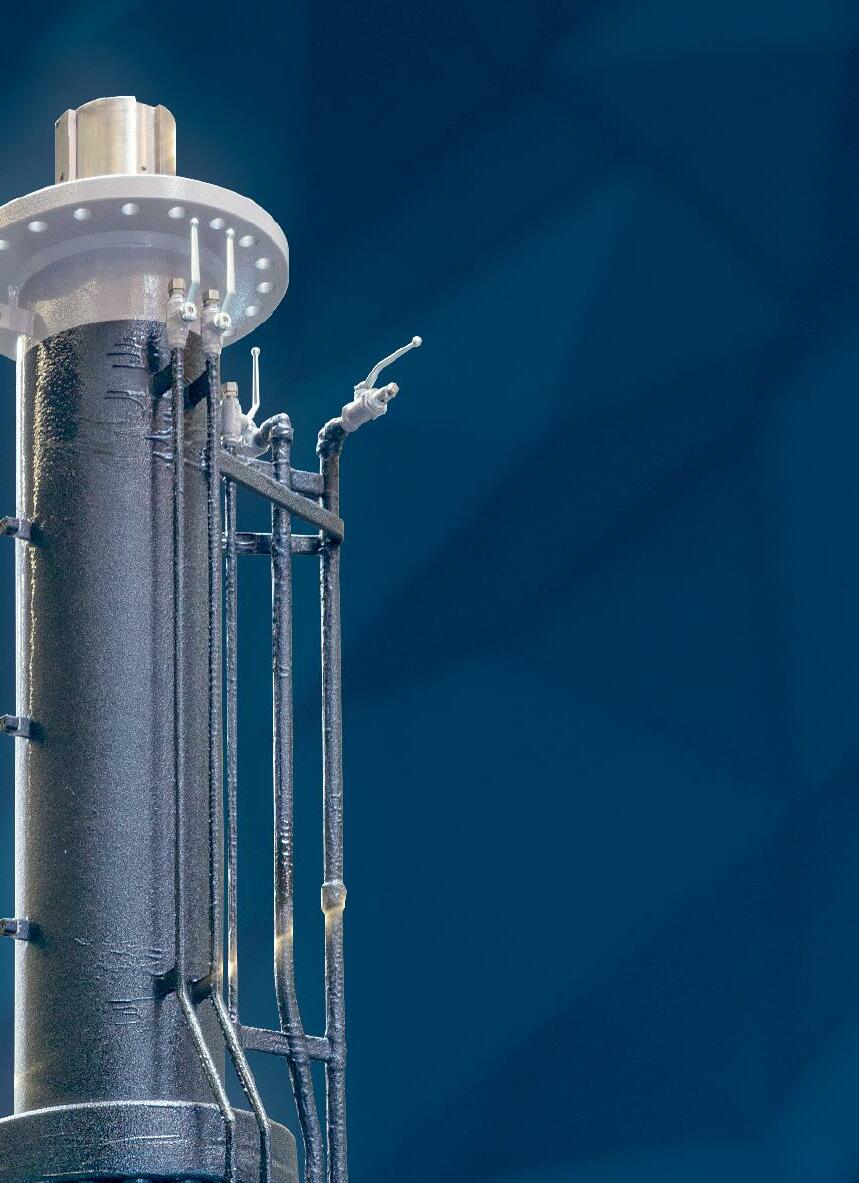
Figure 1. SKELDAR V-200 in flight to offshore oilfield.
There is a heightened need for preventive maintenance planning and optimised production while keeping costs on the low side. UAS provides an alternative to sending fully manned crews on missions. Unmanned aircraft capable of performing the task of inspecting infrastructure are often far more fuel efficient than their manned counterparts, and in the case of rotary-wing platforms do not require hard largescale infrastructure to deploy. In addition to this, spare parts packages are often lower in cost when compared to manned aircraft.
The oil and gas industry faces a variety of safety risks arising from accidents, fires, falls, difficult terrains, hostile communities, and more. Damages and leaks may occur on critical infrastructure such as pipelines, which are difficult to assess as they often cover many miles and sometimes travel through hostile or difficult terrains. This may go unnoticed for some time and expose the community and environment to harmful gases. Light detection and ranging (LiDAR) is one example of an advanced sensor that can detect methane leaks.
Current hinderances to UAS take-up
One of the main issues for the oil and gas industry is keeping costs down. This is why when it comes to assessing the use of UAS, a thorough cost/benefit analysis is required.
In establishing cost-effective practices for the oil and gas industry, not many UAS manufacturers have gone to the trouble of assessing every aspect of a UAS purchase. Global prices for petroleum products can encounter volatile phases, therefore, any investments made must be justified. Europe’s leading provider of rotary UAS, UMS SKELDAR, has made this a focal point when assessing what benefits its platforms can deliver. The company is reviewing every aspect of the development to deployment process to isolate potential areas for cost savings for users. This process incorporates the regulatory requirements.
Over the last decade and more, regional civil aviation authorities have been charged with formulating UAS polices and regulations to keep pace with the needs and requirements of global businesses. Unfortunately, the regulations set have sometimes acted as a barrier to widespread take-up. For example, in many countries, it is still very difficult to fly over populated areas due to heavy regulation, making it hard to undertake missions where there is a vast area to monitor. Although legislation is evolving rapidly as regional restrictions
are eased, and more is understood about UAS from an operational safety perspective, there is still a long way to go.
There are projects that have happened or are ongoing that are assessing how UAS platforms can be safely integrated into controlled manned airspace, such as the ECARO project. ECARO is a multidisciplinary project whose main objective is the adoption of European satellite navigation systems global navigation satellite systems (GNSS), EGNOS and Galileo, for all civil aviation applications including fixed-wing and UAS operations, as well as rotorcraft emergency operations.
As UAS capabilities and usage rates increase, it is pertinent that legislation continues to evolve to allow UAS in UMS SKELDAR’s weight category to be deployed for such tasks as oil and gas pipeline monitoring. Current aviation legislation frameworks are designed with visual line of sight (VLOS) regulations in mind, which means that an operator of a UAS must always be capable of maintaining VLOS of the UAS they are piloting. Beyond visual line of sight (BVLOS) regulations are also in place, which allow UAS to be operated at a distance outside the normal visible range of the pilot. This is the area that is currently being evaluated through a number of tests and demonstrations. The expectation is that BVLOS flights will begin for specific missions, such as oil and gas pipeline monitoring and maintenance. Working together with the oil and gas industry, alongside regulators, is therefore the best route forwards.
Without a doubt, UAS have the advantage of enabling oil and gas operatives to monitor any suspicious activities, as well as check the status of the condition of hard-to-reach oilfields or cross-border pipelines, at a minimal cost. However, government regulations must be progressive enough to provide an enabling environment for the changes needed to thrive while the industry doubles down on improving current technology.
Solutions
The use of UAS in the oil and gas industry is only going to increase in the future. Being able to monitor suspicious activities as well as check the condition of hard-to-reach oilfields or cross border pipelines without putting any person at risk is a significant advantage worth pursuing. Inspecting and maintaining oil pipelines and platforms is a perilous task: many are remote and in extremely harsh environments. Rig inspections carried out by rope-access technicians are not only extremely dangerous operations but can take up to eight weeks, and involve shutting down production (Airborne Drones, 2019).
By capitalising on their endurance, using UAS in these environments means it is possible to access these areas with relative ease, and without exposing crew to the associated hazards. This removes risk to employee safety and consequently reduces medical expenses and lost work hours due to injury.
As well as the associated dangers, the remote location of oil and gas work also presents a challenge in gathering and sharing data. Having manned crews run inspections and repairs means a delay between data recording and analysis. In contrast, using UAS means data can be shared via the cloud in
26 World Pipelines / DECEMBER 2022
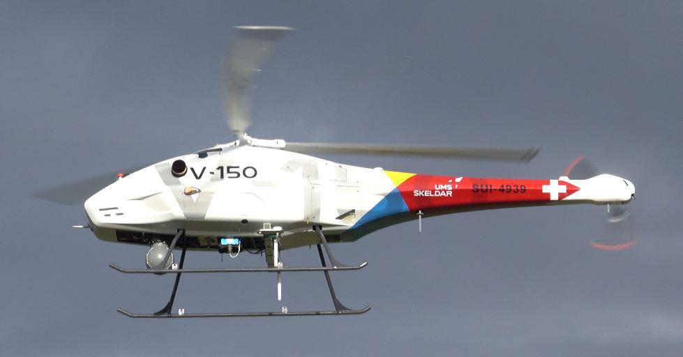
Figure 2. SKELDAR V-150 in flight.
real-time to crews in another location, totally separate from the inspection itself.
Not only do UAS gather information more efficiently than humans, digital data enables operatives to make better decisions based on more accurate data. Once a potential hazard has been identified, it can be addressed in a far shorter time. This helps to identify issues earlier and reduce downtime, which is vital for organisations in charge of safeguarding critical infrastructure.
Today, oil and gas organisations are assessing UAS as they look to move towards non-conventional sources and more challenging environments. This is due to the requirement to ensure round the clock vigilance, a priority in any strategic asset protection plan.
Overall, the key benefits include:
) Providing a quick overview and evaluation of difficult to reach areas.
) Preventive maintenance planning and optimised production keeping costs on the low side.
) Access to locations that pose health, safety, and environmental risk to personnel.
) Real-time data transmission.
) Fast onsite deployment of UAS platforms.
) Authorised and qualified UAS-inspection personnel.
) Reduced downtime increases overall efficiency.
The way forward
After years of advocacy by UAS manufacturers, there is greater awareness in general around what these innovative technologies can provide to an ever-broadening variety of sectors and organisations. However, people in civilian sectors like the oil and gas industry need to be made more aware of the roles and therefore purposes of a UAS. Education is key to the integration across the sector and crucially how we can further employ it as an intelligence asset. That intelligence is gold dust and getting hold of the data a UAS can gather is one thing, but that is only part of the equation.
To really move things forward, the regulations behind the scenes rightly controlling what is possible also need to adjust to the technology advancements that have been made in recent times. Being able to fly BVLOS over land, and not just at sea, is pivotal to what is possible in the future. Many pipelines are not only vast in terms of length, but also across borders. Therefore, regulations should adapt to allow oil and gas organisations to perform monitoring operations. Although significant work is being done in this area, advancements as well as studies are still required to form a legislative framework that allows for operations with unmanned aircraft to take place, where companies not only understand what they have to do, but also the implementation is relatively simple to undertake –without this, UAS system uptake may well continue to be slow.

28
Flow control specialists Tommi Bergman, Manager of Engineering Analysis and Taija Hämäläinen, Director of Butterfly Valves, Valmet, Finland, consider improving process performance in demanding control valve applications.
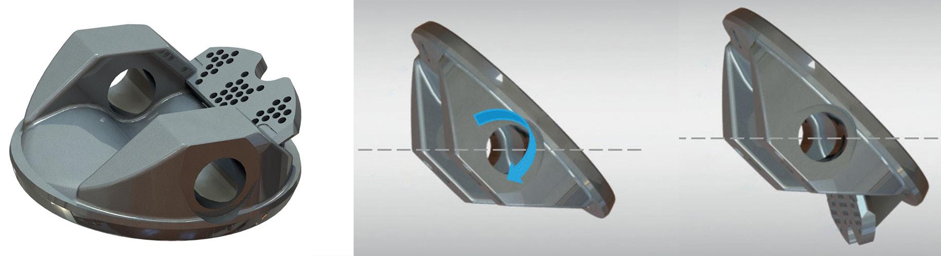
Valmet expanded its offering with flow control solutions in April 2022, when the industrial flow control company Neles was merged into Valmet. In June, the company broadened its new generation versatile butterfly valve product range with the NelesTM Q-DiscTM, a new high-performance feature to help flow balancing in control valve applications. But what makes the new Q-Disc a game-changer? Let’s take a closer look at the Q-Disc design journey to find out.
The Q-Disc flow balancing trim addresses dynamic torque-related challenges in butterfly valve applications. The perforated trim plate is seamlessly integrated with the disc, making it durable, efficient and easy to incorporate into your valve assembly. Q-Disc has been designed to be easy to install, service and maintain as a part of
versatile Neles NeldiscTM and JamesburyTM Wafer-SphereTM butterfly valves. It also provides market leading noise reduction even up to 12 dB.
Neles, now Valmet’s Flow Control Business Line, has a long history in bringing reliable and innovative flow control solutions to the market. In addition to decades of engineering know-how, our design process is based on continuous dialogue with customers, combining experience from tens of thousands of customer installations and translating them into solutions that answer to specific needs of specific industry and process. In the case of Q-Disc, one of the key drivers was to improve process performance in demanding control valve applications that involve challenging media or process conditions, for instance. We also build on and get inspiration from existing innovations: the Q-Disc, for example, helps reduce noise and cavitation like all the other Neles trims under the Q-moniker.
Tackling the dynamic torque
Dynamic torque is a challenge that all rotary valves, especially butterfly valves, face when in active flow control service. However, it is an aspect that is not as often taken into consideration when designing valve solutions and selecting the right configurations. While the requirements brought along by static torque are well addressed, we find that design considerations addressing dynamic torque are often an afterthought. For Valmet’s flow control business line, it was a consideration that was at the core of the design process.

29
Dynamic torque is the flow-induced pressure torque placed on the valve in service. It is a direct result of the operating environment in which a valve is placed. Depending on the flow direction, valve travel, and valve design, dynamic torque may even cause the valve to open or close. Rotary valves in throttling service may experience high torques, especially on larger valve openings. Valmet is seeking patent protection for the innovations that the new Q-Disc is bringing to the table when it comes to tackling the effects of dynamic torque in butterfly valve applications.
Easy selection and sizing for optimal performance
Dynamic torque is also a key factor that has an effect on actuator sizing as a part of the valve assembly. Actuators may easily end up being undersized if only taking static
torque into consideration. Also, when playing with high safety margins, actuators may end up oversized. The Neles NelprofTM sizing software takes dynamic torque into consideration and recommends the correct actuator automatically. Nelprof has all the different actuator characteristics inside, so sizing is accurate for all actuator types.
By taking dynamic torque into careful consideration and making the correct valve-actuator configuration choices, process efficiency and performance can be optimised. The Q-Disc as a part of the valve assembly can deliver potential cost reductions and improvements in efficiency. A stable flow with minimised restrictions to capacity means even output and quality, as well as reduced mechanical stress on valves. In other words, Q-Disc also helps in optimising the entire valveactuator package by making it possible to reduce the impact of dynamic torque caused by the flow, providing improved reliability and efficiency for the overall process the valve is part of.
Improved performance in any and all valve configurations
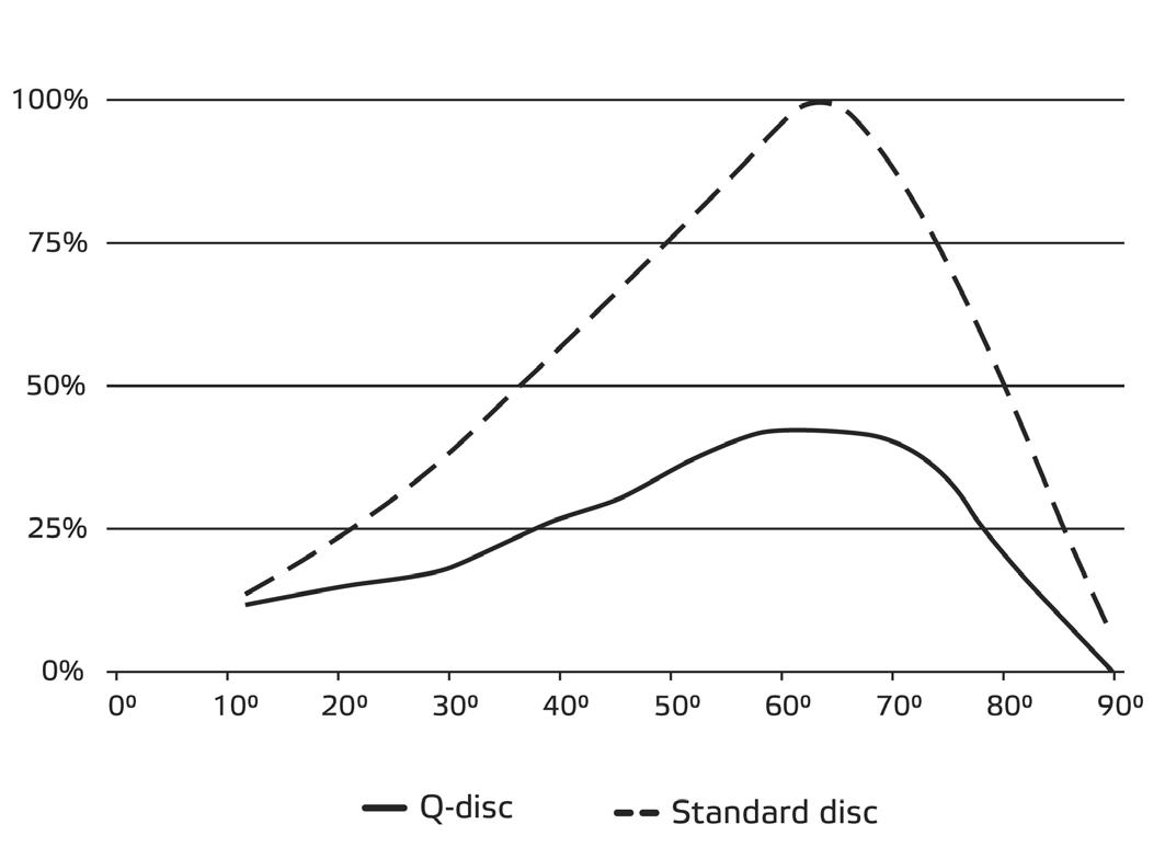
The Q-disc can have a positive effect on the dynamic torque coefficient of a butterfly valve. When looking at and measuring dynamic torque, we need to look at differential pressure and the valve size, or in the case of butterfly valves, the size of the valve disc in particular. As dynamic torque is a result of the pressures created by the flow of media through the valves, things like disc geometry and shaft offsets come into play. The effects of the Q-disc’s integrated flow balancing trim on a triple offset butterfly valve can clearly be seen in the curve shown in Figure 3.
The modular design of our latest range of versatile butterfly valves means that the Q-disc can easily be incorporated into any and all valve configurations. They have been designed by pressure class and valve size to ensure you always find the perfect fit. Speaking of fit, the Q-disc fits neatly inside the valve, requiring no deviations in terms of regular installation or maintenance procedures.
Excellent relative flow capacity with an integrated trim solution
There is no separate external trim plate and no fasteners between the trim and disc. The disc and trim form an
Definition: Dynamic torque and dynamic torque coefficient
Valve dynamic torque (Md), which tends to close or open the valve depending on the type of valve, is caused by asymmetric pressure distribution on the surface of the throttling element, in this case the disc. The dimensionless dynamic torque coefficient (Cd) is a value determined experimentally using laboratory measurements.
30 World Pipelines / DECEMBER 2022
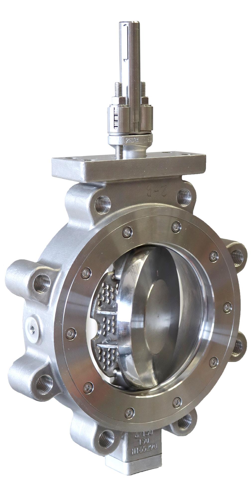
Figure 1. NelesTM Q-DiscTM flow balancing trim for butterfly valves.
Only one call away...


You’re looking for a partner that provides the best service in sales & rental in pipeline equipment. One that deals in all the big brands and offers worldwide delivery. A company you can rely on, one that keeps its promises, thinks ahead and always delivers...


You can build on BAUMA!


BAUMA-PIPELINE.COM
Vermiet- und Handels GmbH
integrated piece with a rigid connection. There is a patent pending on this innovation. This solution has been found to work particularly well with bigger opening ranges. The Q-disc has excellent relative flow capacity compared to traditional flow balancing trims, and flow characteristics that are very similar to standard discs.
And much like the other perforated integrated trims that carry the Q-moniker in the Neles product brand range, the Q-disc also acts to lower noise and cavitation. It has a positive effect on the valve choking factor (FL) and can be particularly helpful in reducing aerodynamic noise to some extent. All in all, the Q-disc is an innovation that was born out of the need and desire to improve process stability and ensure long-lasting performance and reliability. It is literally helping take some of the pressure off the shoulders of the butterfly valve’s disc and shaft.
Simulation-driven development process
The key to a relatively fast journey from idea to market has been the efficient utilisation of simulations in the design and proof of concept phases. As a part of the process, tens of initial designs were iterated, and the final design was selected to best accommodate the modular design and overall performance. After considerable testing
and verification, this winning design is now seeing the light of day as a part of the first pilot cases in full operation. So many factors had to be considered before we had a final prototype in hand; dynamic torque, flow capacity, cavitation, noise, compressible flow, to mention a few. The computational fluid dynamics analysis shows that performance figures are as expected. The structural analysis shows the needed strength and reliability of performance.
From
simulation to day-to-day value
For us data simulations are the backbones of efficient innovation and design processes. The final verification of performance obviously still comes from stringent testing and piloting procedures. We are convinced that the new Q-Disc is bringing tangible performance and reliabilityrelated benefits to our customers in a package that is designed to be easy to assemble, install, service and maintain.
Today, Q-Disc is available as an option for a wide range of Neles Neldisc and Jamesbury Wafer-Sphere butterfly valves. For more than 40 years these valves have been the go-to valve for many industries and applications all around the world. Versatility and reliable performance have been driving forces behind the design of our new generation of butterfly valves. Also, the role of sustainability in industry, business and society at large has been a key factor in the development of these products. The new generation versatile butterfly valve platform delivers new functionality while leaning on field-proven technologies and decades of experience to meet the challenges of modern and future industrial processes.
The new generation of Neldisc and Wafer-Sphere butterfly valves are based on the same technology platform, sharing many design features, modular components and tangible customer benefits. The highest Cv on the market, paired with the low torque requirement make for excellent energy efficiency. The valve design that minimises fugitive emissions further improves energy efficiency, process yield and overall sustainability. For us, this is an example of what the future of efficient, reliable and sustainable industrial design looks like.
Figure 2. The Q-disc seamlessly integrates the perforated trim plate with the disc.
32 World Pipelines / DECEMBER 2022
Figure 3. The Q-disc has an excellent relative flow capacity compared to traditional flow balancing trims.

Rescuing a stalled cleaning pig isn’t usually on the prepipeline isolation to-do list. After all, most pigs travel through pipelines without a hitch, doing their job of improving throughput across thousands of miles of line each day. So, when a third-party vendor’s bi-directional (Bi-Di) cleaning pig stalled in the production tee of a 28 in. natural gas
export pipeline offshore southeast Asia, it came as a surprise to the operator.
Although the pig wasn’t entirely obstructing product flow, the operator was worried that inline conditions could increase both pressure and bypass. If that happened, it could push the pig further into the pipeline and create a blockage that could shut down production for days if not weeks. With gas export pipelines like this one transporting millions of dollars in product every day, the operator was highly motivated to avoid that possibility.
A potential service interruption wasn’t the only urgent reason for extracting the stalled pig, however. The operator had discovered that two pig trap valves on the platform were
internally leaking, meaning they didn’t seal completely. The company was understandably eager to get them replaced.
Replacing leaking valves is not uncommon, but it requires creating a safe work zone first. And that means the operator must make a choice that can affect production, downtime and the environment. Either they can blow down the entire pipeline to make it hydrocarbon-free, or use inline methods to isolate just the section where the work will take place.
Considering that depressurising the entire 300 km (186 miles) pipeline would result in something like 300 million ft3 of inventory loss through flaring and would add a week to the turnaround time, it hardly seemed like a viable option to the
 Rolf Gunnar Lie, T.D. Williamson, Asia Pacific, introduces a bespoke recovery tool that rescues stalled pigs and enables isolation.
33
operator. Knowing that T.D. Williamson (TDW) SmartPlug® technology had been proven in offshore operations made their decision to go with inline isolation even easier.
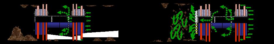
Of course, before TDW could even think about isolating the pipeline, the third-party stalled pig had to come out, or it would prevent them from pigging the SmartPlug tool to the set position. And before TDW could rescue the pig, they had to do two things: figure out why it stalled in the first place, and develop a bespoke recovery tool.
First things first
Recovering a stalled pig isn’t like getting a clog out of a drain – it can be a complex undertaking depending on where the pig has become stuck in the pipeline.
The most commonly used pig-rescue solutions involve blowing down the entire pipeline, something everyone in this case wanted to avoid. Instead, the technical experts at the TDW Global Center of Excellence in Stavanger, Norway, designed, manufactured, tested and mobilised a 100% engineered to order application-specific solution they could perform without the operator having to flare the entire gas contents of the pipeline, which would have generated significant amounts of CO2 emissions.
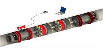
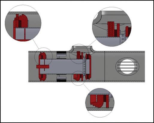
The first step, though, was determining why the third-party pig became stuck. As TDW Project Manager, Stephanie Craig explained, knowing what caused the pig to stall was necessary not just for removing it. The answer would provide insight into a long-term solution related to future pigging operations. TDW engineers discovered the problem could be traced back to incompatibility with the pipeline system.
“To be fair, both the operator and the original pigging service provider expected there would be a considerable amount of debris in the pipeline for the Bi-Di pig to sweep out – so much so, in fact, that the buildup could cause the pig to stall unless certain precautions were taken,” Craig said. “To try to prevent the pig from stalling, they had built bypass into the pig by drilling holes in its body. The idea was that the holes would allow a portion of the gas to flow through the pig, creating turbulence ahead of it that would either flush out the debris or at least make it easier for the pig to remove.”
Unfortunately, these good intentions contributed to the stall. Designing a pig with bypass can be tricky: there needs to be enough bypass to create turbulent flow in front of the pig, but not so much that it reduces the differential pressure driving the pig. In this case, the Bi-Di pig allowed a relatively large volume of gas to flow through it, meaning it had less differential pressure behind it. At the same time, its heavy polyurethane disc stack-up required more differential pressure to move it compared to a conventional Bi-Di pig. In short, the design simultaneously demanded more pressure but produced less. To complicate things even more, as the pig entered the barred production tee, a segment of the discs partly disengaged the seal, creating additional bypass. In the end, there simply wasn’t enough drive on the discs to push the pig any farther.
An engineered solution
With time ticking away on their much-needed valve replacement project, the operator considered multiple alternatives for recovering the stalled pig. Among them was the possibility of using another Bi-Di pig to push it back to the onshore receiver. However, the project team was
Figure 1. SmartPlug® double block and monitor system.
Figure 2. Third-party bi-directional (Bi-Di) pig stuck in the barred production tee.
34 World Pipelines / DECEMBER 2022
Figure 3. Effect of bypass on debris: without jetting head or bypass (left); with jetting head or bypass (right).
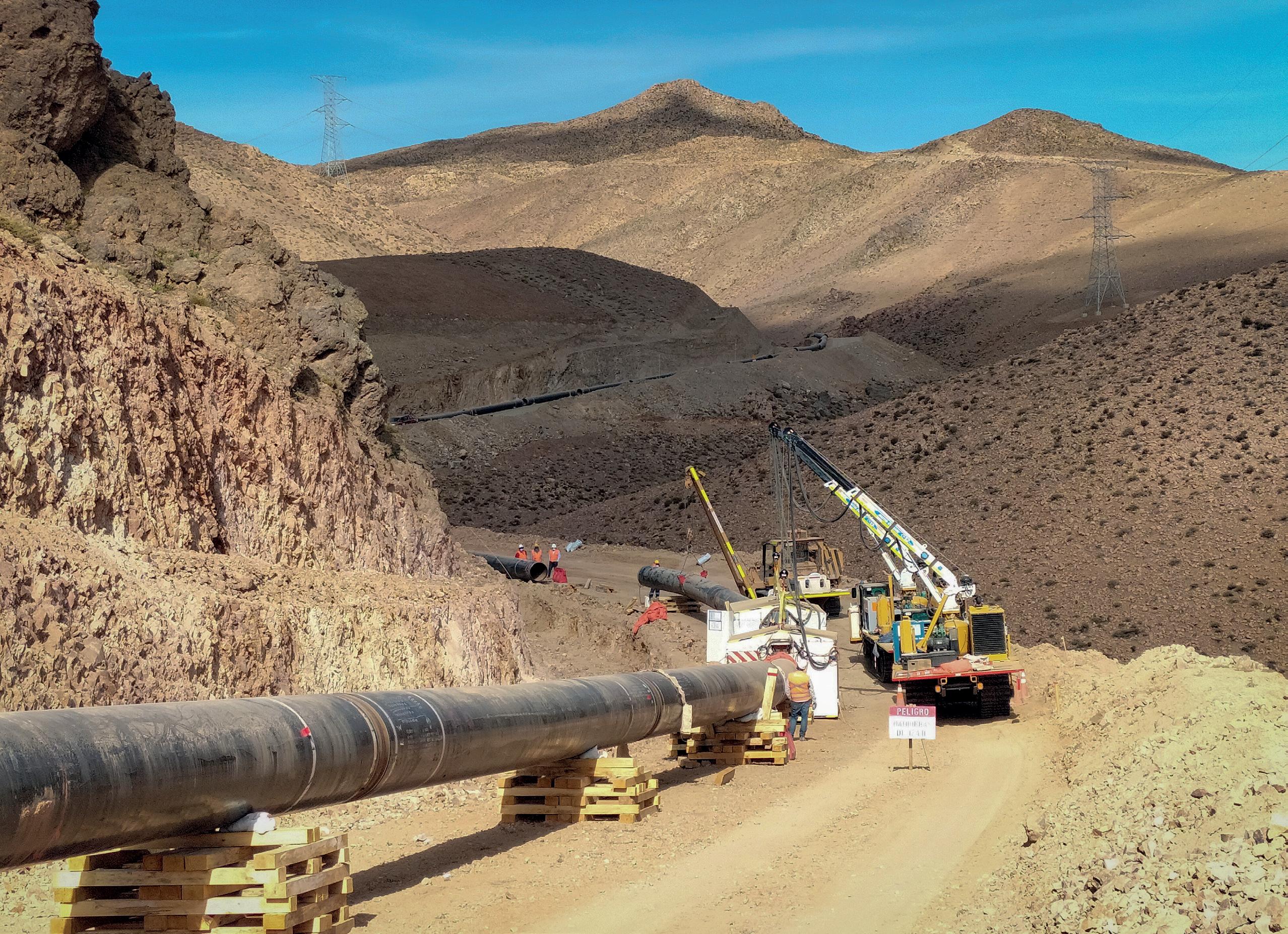
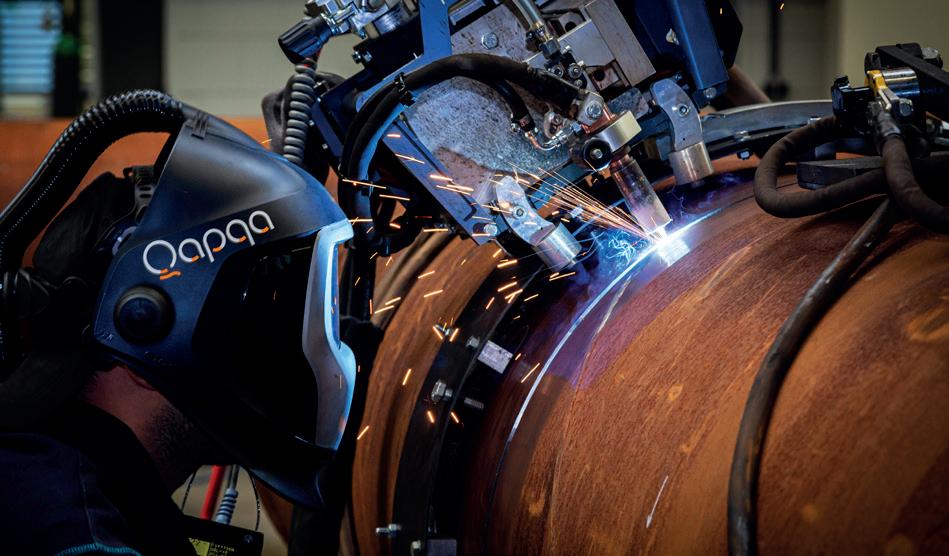
• Increase productivity • Increase quality • Lower repair rates • High level
support
project - Chile
of
Techint
Together, we create the most distinctive and integrated welding solutions for the construction of reliable and sustainable pipelines. As a family business, we think long term. Dedicated and continuously improving, we always challenge ourselves to go the extra mile. Qapqa. Joining solutions.
concerned that the pig would get stuck as it tried to traverse the many bends between the pipeline and the platform riser. Trying to rescue it further down the line would require a challenging subsea operation.
For TDW, it had become clear there was only one way to safely recover the pig without blowing down the pipeline: they would have to pull the pig back to the launcher. Of course, since situations like this are exceedingly rare, there’s no standard recovery tool on the market. Instead, TDW had to engineer and build a solution from scratch. They designed a gripping tool with spring-loaded arms that would snap into place on the bypass holes of the pig body, with a lance to install the tool and a hydraulic system to pull the pig out. A ‘strong hold’ anchor point operation was installed a distance from the launcher quick opening closure to be attached to a pulling wire. To overcome limited visibility inside the launcher, engineers incorporated a camera system so they could see that the gripping tool remained engaged with the pig.
The right force
Designing an effective recovery system was just a start, though. Engineers also had to determine the appropriate amount of recovery force for the operation. During pigging, the outer edges of the discs are folded backwards. To be able to pull the pig out requires putting enough pressure on the discs so they fold in the opposite direction, often referred to as ‘flipping pressure’.
To accurately test the effect of various differential pressures on the pig’s sealing discs, TDW manufactured a replica test rig of the offshore pipeline, including the barred production tee, at the Stavanger facility. The operator furnished a Bi-Di pig identical to the one that had stalled.
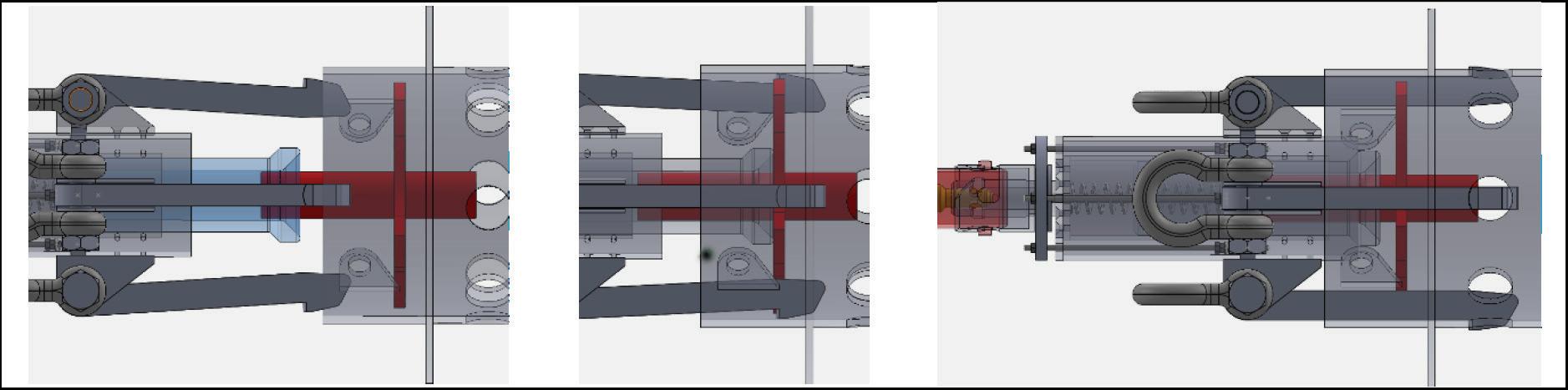
After a series of recovery force tests, including one in which the pig stalled and another where the disc packs partially burst, engineers landed on the optimal force to use during retrieval. With that information in hand, they could feel confident manufacturing the recovery tool. To be certain it would work as intended, they conducted a retrieval test in the pipe replica using the same Bi-Di pig, now equipped with new discs.
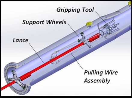
“The test enabled the engineering team to visually inspect and ensure the integrity of the recovery tool and pig body, and to monitor the force required for the recovery tool to pull the pig,” Craig said. “In addition, by recording the time it took to assemble the lance, engage the tool and retrieve the pig, TDW understood how to optimise procedures to limit downtime.”
All of the preparation paid off onsite. In fact, the actual retrieval time was just five hours. In less than a day shift, the TDW offshore team:
) Assembled the lance and gripping tool and inserted them into the pipeline.
) Locked the pig gripping tool in place in the pig’s bypass holes.
) Hooked up the pulling wire.
) Retrieved the pig from the launcher.
Isolation success
With the stalled pig safely removed from the pipeline, TDW isolation and intervention teams could mobilise for the SmartPlug operation, which would enable the successful replacement of the leaking valves without having to remove the pipeline’s entire gas content.
Inline isolation involves pigging an isolation tool to the desired position and establishing the isolation at the identified point. Existing pig traps and quick opening closures are used at the point of entry into the pipeline and the point of exit.
The SmartPlug inline isolation tool provides full doubleblock isolation. Broadly speaking, a barrier is deemed to be ‘double’ when each plugging module can retain the full line pressure individually, it is tested and its integrity is monitored.
Figure 5. Pulling lance attached to gripping tool.
36 World Pipelines / DECEMBER 2022
Figure 4. Design of gripping tool interface with pig body.
Each SmartPlug plug module is capable of full isolation of the pipeline, giving the tool 100% contingency. The SmartPlug isolation remained in place for six days.
A clean sweep
With the stalled pig out of the way and fully functional pig trap valves in place, it was time to tackle the next phase of this multifaceted project: cleaning the pipeline.
Given that the line hadn’t been pigged in more than two years – and that the foam pigs the operator ran the last time returned significant amounts of debris – the TDW pigging team was concerned about the possibility of excessive buildup. A large accumulation of debris can be a threat to a conventional, onesize-fits-all cleaning programme. It takes an engineering study to evaluate proper pig design and a piggability study to ensure the right approach and mitigate risk.
To avoid potential difficulties – including the possibility a cleaning pig would get stuck in the debris – TDW recommended progressive pigging. Just like it sounds, progressive pigging means launching a series of increasingly aggressive pigs. The process typically starts with low or medium-density foam pigs, then moves up the spectrum to hard-bodied pigs, often equipped with blades or wire brushes. The sequence avoids removing too much debris at once, which can affect pig performance, yet it’s highly effective at achieving the required cleanliness standard.
In this case, TDW developed a new cleaning pig to fit the pipeline systems’ specific requirements, and to avoid a repeat of the original stalled pig scenario. Engineers reconfigured the proven Vantage® cleaning pig with RealSeal® cups. The cups would provide a tight seal inside the pipeline, and help the pig maintain a low differential pressure as it travelled through the pipeline system, including through the production tee where the Bi-Di pig had stalled. Adjustable bypass was incorporated with jetting nozzles to prevent debris build up in front of the pig. The use of adjustable bypass created the ideal amount of turbulent flow in front of the pig during each Vantage pig run. The Vantage pig was equipped with the SmartTrackTM pig tracking system. Once cleaning was completed, the operator resumed their normal pigging protocols and could perform inline inspection (ILI).
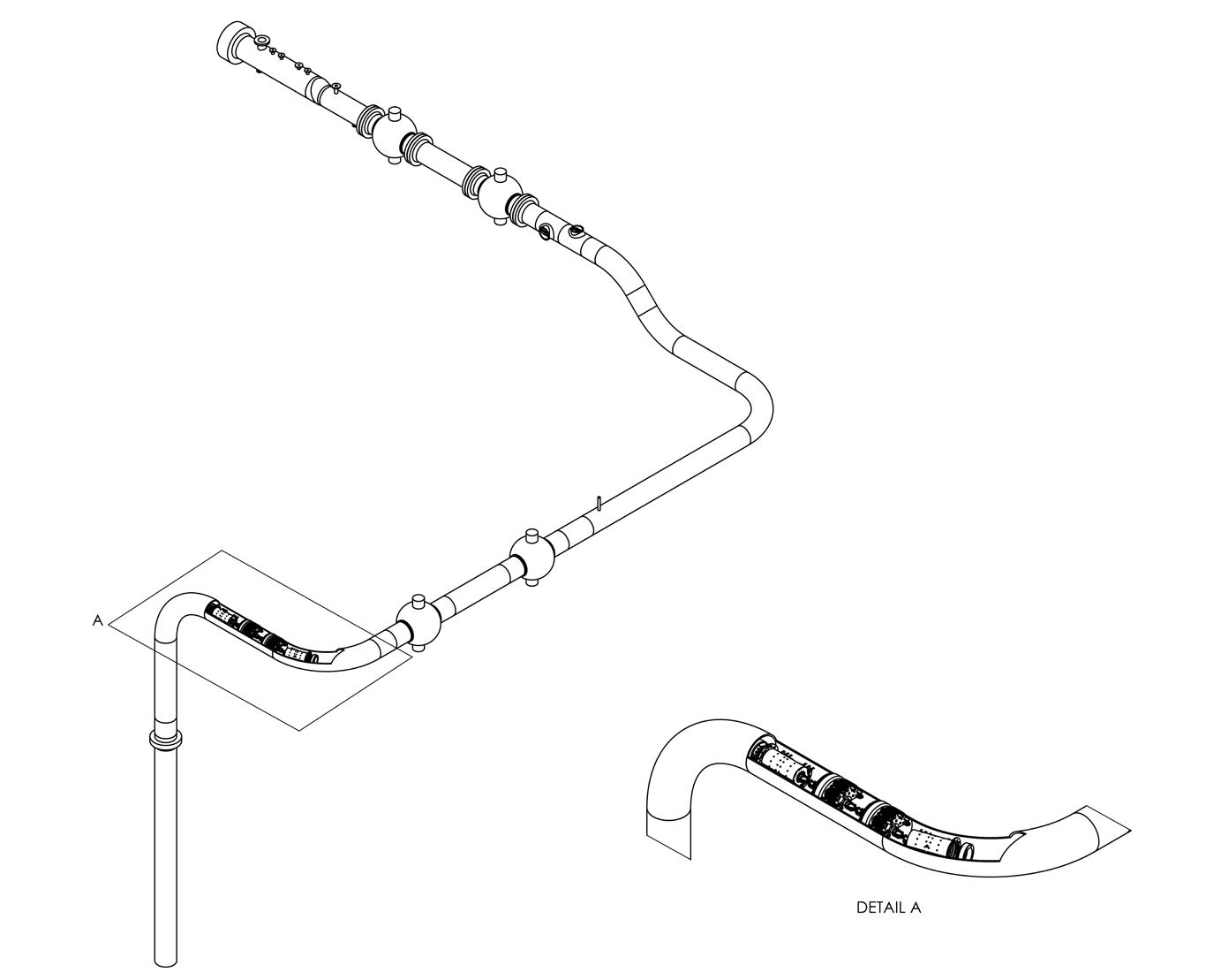
Checking all the boxes
While pigging is generally a routine operation, it’s not something that can ever be left to chance. In this case, launching a pig that wasn’t suited for the pipeline created repair delays, but it could have led to considerable financial losses. Through teamwork between the operator and TDW, including site visits, design reviews, and testing, TDW was able to optimise both the pig recovery tool and
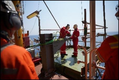
procedure. TDW helped avert the potential nightmare of the stalled pig moving farther into the pipeline, enabled efficient repair of leaking valves by use of SmartPlug isolation, and restored the system’s integrity – and did it all while the system remained pressurised. Compared to flaring, this saved about 15 630 t of CO2, or roughly the annual emissions produced by 3400 internal combustion engine passenger cars.
After TDW performed progressive pigging, the pipeline was clean enough for ILI. Since then, the operator has made regular pigging with TDW pigging an essential part of its integrity plan. Ultimately, working with TDW enabled them to check off all the boxes on their to-do list for safety, efficiency, sustainability, and performance.
Figure 7. The SmartPlug inline isolation tool was pigged to the set location, enabling the valve replacement project.
DECEMBER 2022 / World Pipelines 37
Figure 6. Strong hold anchor point to attach the pulling wire.

38
afe and efficient transmission of product via energy pipelines has become more important than ever due to the growing need to efficiently manage an evolving product mix that includes newer products, such as biofuels and renewable natural gas (RNG), along with petroleum-based products. Global trends and shifting public opinion have led pipeline operators to focus increasing effort on eliminating transmission delays and leaks, which can only be accomplished through careful monitoring of every mile of a pipeline. However, not every mile of every pipeline will have access to a reliable communication backbone capable of delivering real-time data securely.
To overcome these obstacles, field operations and operational technology (OT) teams are pursuing new combinations of software, technologies, and communication infrastructure to address the challenges of unreliable networks, while simultaneously improving cybersecurity across the entire pipeline. Distributed network protocol 3 (DNP3) is at the heart of this shift, prompting forwardthinking organisations to include it as part of their future automation strategy.
The importance of robust pipeline protocols

To ensure safe, effective transmission of product across miles of pipeline, operators and maintenance personnel need constant and clear visibility into what is happening in even the most remote locations. To enable this visibility, teams need a communication infrastructure that ensures data is provided reliably and delivered efficiently, while simultaneously minimising the risk of cyberattacks.
One of the most common strategies teams rely upon to ensure data integrity is storing historical data in remote terminal units (RTUs). When everything operates as planned, RTUs gather data from the pipeline and transmit it to a supervisory control and data acquisition (SCADA) system, in real-time or near-real-time. However,
The energy industry is rapidly embracing the DNP3 protocol for fast and cybersecure pipeline monitoring, suggests Steve Hill, Emerson, USA.
39
many pipelines traverse remote areas with little or no reliable communication infrastructure (Figure 1).
In remote areas, operators and maintenance personnel rely on cellular modem, satellite communication, or other technologies to transmit data to the SCADA system. Often, these communication technologies are too unreliable to guarantee consistent real-time communication. The teams monitoring the pipeline know they will intermittently lose connection and design their infrastructure accordingly.
When the connection drops, modern RTUs typically store historical data, with metadata including an accurate
time stamp to ensure accuracy of information. When the connection is restored, the RTU automatically transmits stored data to the SCADA system, which backfills the information in its database. This ensures that consistent, contiguous datasets are available for data analysis, which may not be possible, or as accurate, if even a small subset of the original raw data is missing.
One of the most critical tasks when analysing this historised and backfilled data is leak detection. The calculations for leak detection are complex, requiring a complete view of variables – such as temperature and pressure – across the pipeline, requiring data timed accurately with no gaps. For many leak detection mechanisms, it is important that the data is gathered at the same time, with a need for accuracy in the millisecond range. Because it takes time to transmit data – either due to intermittent communications or simple latency on the network – backfilling data with accurate timestamp metadata generated at the RTU is essential to timely and accurate leak detection.
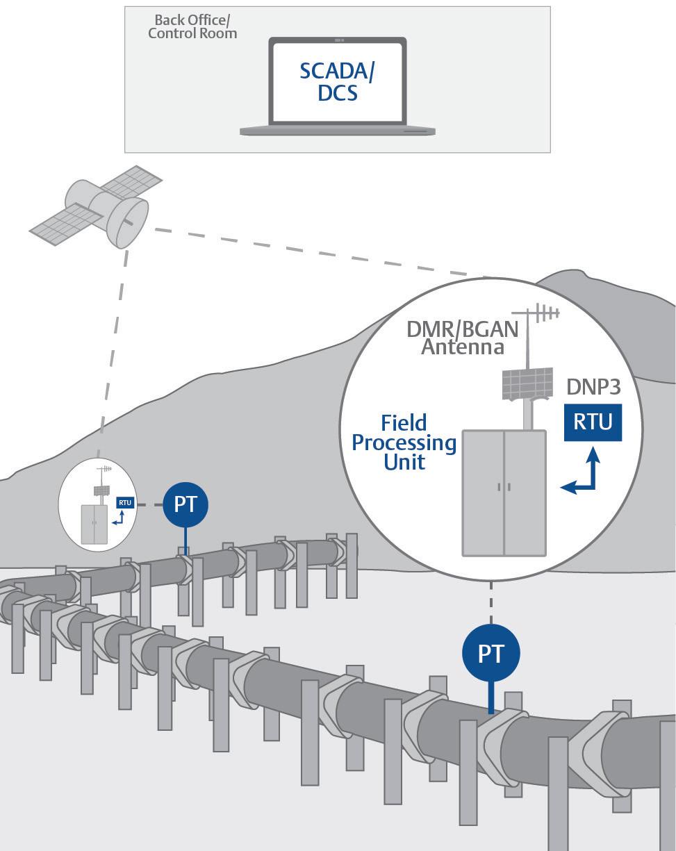
Moreover, speed of the network is essential. Even with historised data, operators and technicians want visibility as quickly as possible. As a result, they rely upon protocols that minimise bandwidth requirements to ensure fast and reliable communication.
New challenges stem from modern problems
Many of today’s pipeline operators – especially in the US –rely on the Enron Modbus protocol to transmit critical data from RTUs in the field to the SCADA system in the control room. When it was developed, Enron Modbus was the gold standard for fast, reliable transmission of data across pipelines because it allowed users to transmit historised data across the network by using extensions to the Modbus RTU industry standard protocol.
Decades after its introduction, however, Modbus is showing its age. Because pipelines are critical infrastructure, they are prime targets for cyberattacks; today’s pipeline operators need cybersecure technologies to move data across their networks, and Modbus is not a cybersecure protocol.
Figure 2. Modern RTUs designed for the DNP3 protocol enhance the reliability and security of critical data, while helping to future-proof pipeline operations.
40 World Pipelines / DECEMBER 2022
Figure 1. Emerson is at the forefront of bringing the DNP3 protocol to the energy industry to provide fast and secure transmission of data between RTUs in the field and the SCADA system.
Expect A Higher Standard

It is possible to mitigate the cybersecurity risk of Modbus by implementing additional defence-in-depth layers, such as encryption and firewalls. However, best practices for defence-in-depth require each layer to be cybersecure on its own, meaning the protocol running inside of those firewall and encryption layers should itself be cybersecure.
Moreover, Modbus has never been fully defined as a standard. As a result, using Modbus can make it difficult to troubleshoot connection issues between devices and the control system. Varying data types, byte order differences, floats, and more can all create issues when they differ between RTUs and the SCADA system, making the integration of devices and software from different vendors even more complex.
Some SCADA systems and RTUs support secure proprietary protocols in addition to Modbus, but even this solution has its drawbacks. While proprietary protocols can increase cybersecurity and simplify connectivity, they significantly limit the selection of equipment available for use in the field. Users are limited to RTUs and other devices that support those same protocols, which can often result in vendor lock-in and difficulty finding and retaining personnel who can support the more obscure protocols.
A better alternative
In a world of more open automation, pipeline operators are recognising the value of protocols with a wider range of connectivity to devices, while still supporting cybersecure communication. Teams planning projects no longer accept a binary choice between proprietary protocols which limit their options, and Modbus which is not cybersecure. Fortunately, the electrical industry had a similar issue for years, and it developed a secure and extensible protocol that eliminates the need to choose between security and flexibility: DNP3.
While the electrical industry uses DNP3 to manage digital, high-speed data, it can also be used to transfer slower, analog data – like that used to monitor pipelines. As a result, the pipeline industry is rapidly adopting DNP3 as a standard
to transfer oil and gas electronic flow measurement data from RTUs to SCADA systems.
The greatest value of DNP3 is that it is secure, yet fast. DNP3 is optimised for high-speed communications, allowing data to be transferred across the network by exception as it changes, while including the same timestamp metadata as Enron Modbus. In addition, DNP3 includes support for secure authentication between RTUs and the SCADA system.
Any time a user performs a critical transaction – for example, writing to outputs to open a valve or shut down a device – the RTU and SCADA must authenticate with each other for confirmation that both are exactly the devices or systems they claim to be. This authentication also prevents person-in-the-middle attacks, where messages are tampered with in transit across the network.
But in pipelines, cybersecurity cannot come at the cost of availability or performance. If every protocol interaction on the network is encrypted, the bandwidth required will generate network latency that can cause availability issues, making it difficult to implement with relatively lowperformance field equipment.
To avoid this problem, DNP3 is not an encrypted protocol. Most communication via DNP3 is unencrypted, and authentication is only performed when required for sensitive activities. This makes the most efficient use of available bandwidth, and it has the advantage of allowing for the capture and analysis of communications with offthe-shelf network analysis tools. This empowers engineers and technicians with powerful and familiar tools when troubleshooting issues, giving them similar capabilities to the familiar legacy Modbus protocol.
Moreover, the unencrypted nature of DNP3 enables the use of third-party network analysers and dissectors, for example, artificial intelligence and machine learning algorithms to further increase oversight of the network. These technologies can monitor DNP3 traffic for suspicious activity and send alerts when they detect aberrations, adding an additional layer of warning, even if the SCADA system is compromised. Teams needing additional cybersecurity can add encryption over the top with transport layer security or a virtual private network.
DNP3 is also extensible, offering additional flexibility. For example, Emerson has extended the DNP3 protocol to carry RTU files containing critical electronic flow measurement data, alarms, and events. Should communication be lost when an event – such as overpressure – occurs and dissipates quickly, logged alarms in the devices, transmissible by extended DNP3, ensure operators have visibility to the alarm, even if it occurred during the communications outage. The inclusion of historical metering data in these files provides a level of buffering and backfill beyond that supported by
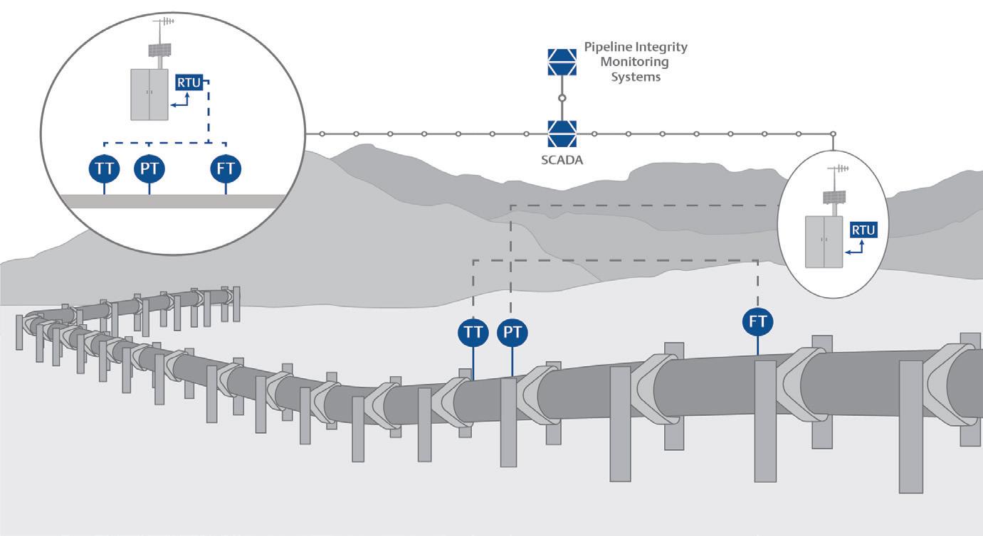
42 World Pipelines / DECEMBER 2022
Figure 3. The DNP3 protocol is optimised to allow data from multiple devices, including Emerson’s FB3000 RTU and RosemountTM transmitters, to be transferred by exception across the network.
standard DNP3, even allowing data to be re-collected if it is lost after the initial collection (Figure 3).


Modernisation is an opportunity for a DNP3 foundation


Being ready for the future of pipeline operation means starting to lay the foundation for DNP3 as a standard protocol. Winning the future of energy transmission will mean moving away from legacy standards and embracing the technologies that will drive secure and efficient pipeline operations well into the coming decades. Already in the Middle East, Asia Pacific, and Europe, many pipeline operators and production facilities are requiring DNP3 in their requests for proposal on new projects.
While adoption in the US has been slower, it is starting to gain momentum. As the popularity of DNP3 as a standard grows across the globe, it will offer pipeline operators and production facilities a wider selection of equipment and greater flexibility of design when considering new designs as part of a modernisation.


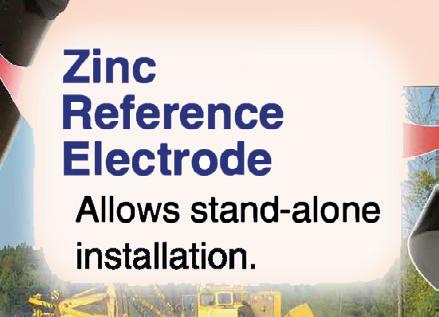
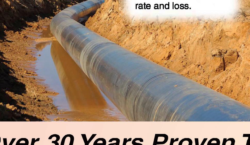
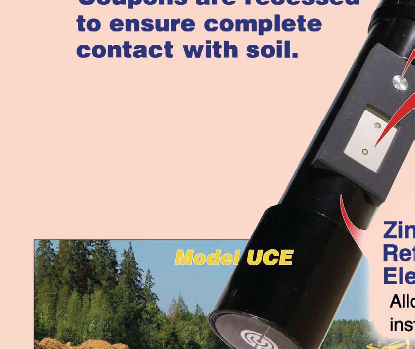


To prepare for this transition, leadership can begin adding DNP3 as a requirement in the request for proposal process for any new automation projects. Typically, the lifecycle of a control system is about 15 years, so preparing today for a foundational technology will help future-proof investments, avoiding the need to rip and replace equipment that was not prepared for a technology shift on the horizon.
Preparing for the future

The need for devices that store and contextualise historical data to support trending and diagnostics across a pipeline network is not going away any time soon. But while many companies use RTUs supporting that technology today, those same devices are often not able to provide the secure communication required to keep their investments and reputations safe as cybersecurity threats increase (Figure 2).


Defence-in-depth is only as strong as its weakest layer, and a layer with no security is a liability to the entire system. Open technologies like DNP3 provide the security pipeline operators need, without sacrificing the performance that supports availability. In the coming years, more and more vendors will begin to support DNP3 in SCADA systems and RTUs, likely making it the de-facto standard for communication, and unlocking flexible pipeline management options that will become the new industry best practices. It is not too soon to begin preparing for that transition, building a foundation of flexible, secure communications infrastructure that will protect


• OUTSTANDING LIFE SPAN • FAST AND EASY INSTALLATION • FOR HIGH-VOLUME FLOWS • HIGH-QUALITY MATERIALS • EXPERTISE IN PLASTICS PROCESSING AGRULINE XXL PIPES HDPE piping system for high volume flow agru Kunststofftechnik Gesellschaft m.b.H. | Ing.-Pesendorfer-Strasse 31 | 4540 Bad Hall, Austria | www.agru.at |
Data is absolutely key for owner operators to make insightful decisions when it comes to extending an assets life, says Jim Bramlett, Tracerco, USA.
ccounting for nearly 55% of global energy consumption, oil and natural gas continues to be the world’s leading fuel. As the global energy mix is transforming, majors and smaller players across the globe are recognising the need to invest in and further extend the lives of their petroleum assets to meet current and future demands.
Over the last few years, asset life extension has been a huge area of focus for operators – and will continue to remain at the forefront – with a real drive to prolong their assets and avoid the need for early decommissioning.
Significant advances in data-driven inspection technologies are playing an integral role in enabling operators to get more life out of their existing

45
assets – such as platforms, pipelines and risers – in a safe and economic way, ultimately maximising production and profits.
One of the world’s leading industrial technology companies that specialises in creating unique and specialised detection, diagnostics and measurement solutions is urging operators that early engagement with inspection experts is absolutely key to successfully extend an asset’s life.
Jim Bramlett, Tracerco’s North American Commercial Manager, explains that in his experience – stemming across almost three decades in the field – operators need to start planning two years prior to an asset’s permit ceasing in order to get the right data needed to make informed and practical decisions to determine an asset’s future.
“Over the last decade, there has been a real shift in the oil and gas market – largely driven by the fluctuating cost of oil that has led to companies across the supply chain as a whole to streamline operations, reduce costs and decrease downtime,” continued Jim, “And with advances in technologies, this has been absolutely instrumental in helping companies to do exactly that – particularly when it comes to extending asset life.
“As the assets have paid for themselves by the end of their anticipated life, it makes absolute sense – if feasible and insights indicate it is safe to do so – to invest in extending the life further, allowing those assets to become of huge value to operators and pivotal in driving profits.”
Challenges in testing and inspection
As assets age over time, oilfield professionals are continuously faced with the test of ensuring efficient production and pipeline integrity. Inspection of these subsea pipelines has often presented challenges where pigging is not an option or deemed too risky.
Historically, inspecting a pipeline from the outside was costly and often an ineffective high-risk operation. Advances in technology are now making it possible to allow companies to make better decisions about their operations, and Tracerco’s Discovery TM technology has been specifically designed to provide accurate, in-depth and real-time data insights.
Breaking barriers
Tracerco is the very first of its kind to develop an inspection technology designed to eliminate challenges on the inspection and maintenance of pipelines; by allowing the online inspection of a pipe from the outside without the need to remove the protective coating or interfere with production. The Discovery technology is already a proven global success, and has been adopted by oil and gas operators worldwide.
Tracerco’s Discovery technology was developed to provide owner operators with an enhanced understanding of a pipeline, its coating and process fluid – all whilst fully operational – and has fast become the market leader with the technology deployed on assets across the globe; most recently including hundreds of pipelines and risers inspected in the Gulf of Mexico and West Africa.
The company’s pioneering subsea CT scanning technology – commonly used for non-invasive medical diagnostic technique – has revolutionised pipeline inspection by providing critical flow assurance and integrity data without the need for coating removal and, in real-time.
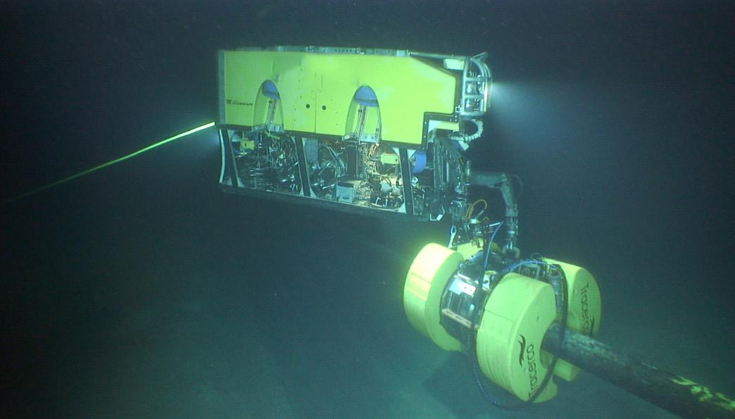
The technology has been used in a wide variety of pipeline designs to investigate both internal and external corrosion, and is the only technology of its type to do so. Furthermore, it can also characterise and locate blockages, as well as other flow issues.
As such, Discovery is an ideal solution for flow assurance and integrity specialists concerned with subsea pipelines that cannot be inspected by conventional means, such as ILI tools or on pipelines where operators want an alternative to the intrusion and loss of production ILI tools present, or validation of ILI results.
Market demand
Speaking about the success of Tracerco’s unique technology, Jim said: “The Discovery technology was designed purely to eliminate the challenges facing operators on the inspection and
46 World Pipelines / DECEMBER 2022
Figure 1. Tracerco’s Discovery™ technology on an ROV.
Converting a mechanical pipelayer with a MIDWESTERN hydraulic conversion kit is a cost effective way to update your older pipelayers. Our hydraulic conversion kits are easy to install and provide precise, simultaneous control of load, boom and counterweight functions, along with an integrated hydraulic boom stop, allowing the operator to focus more on the job at hand.
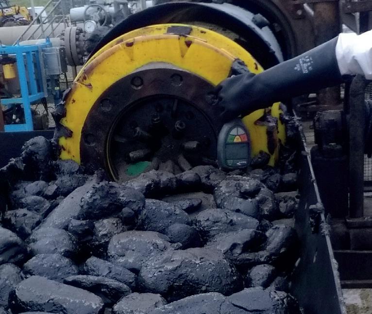
We offer a complete line of hydraulic conversion kits for mechanical pipelayers, with optional certified ROPS, reeving accessories and operator aids. Count on Midwestern to stay ahead of the ever changing needs in the pipeline industry.
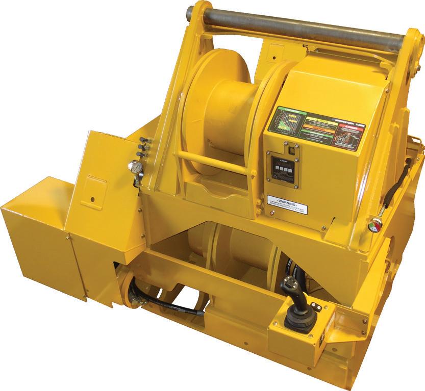
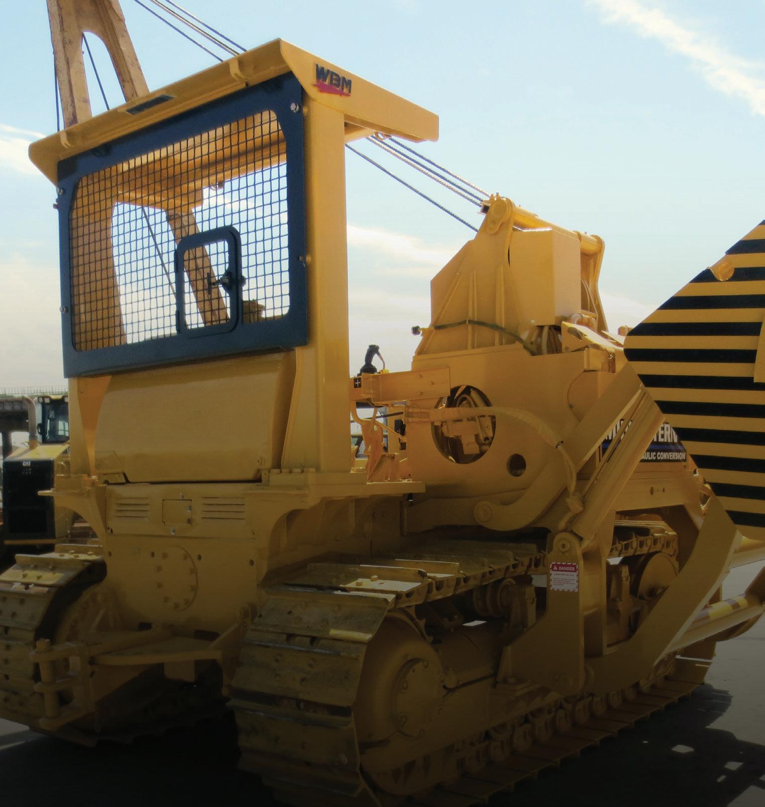
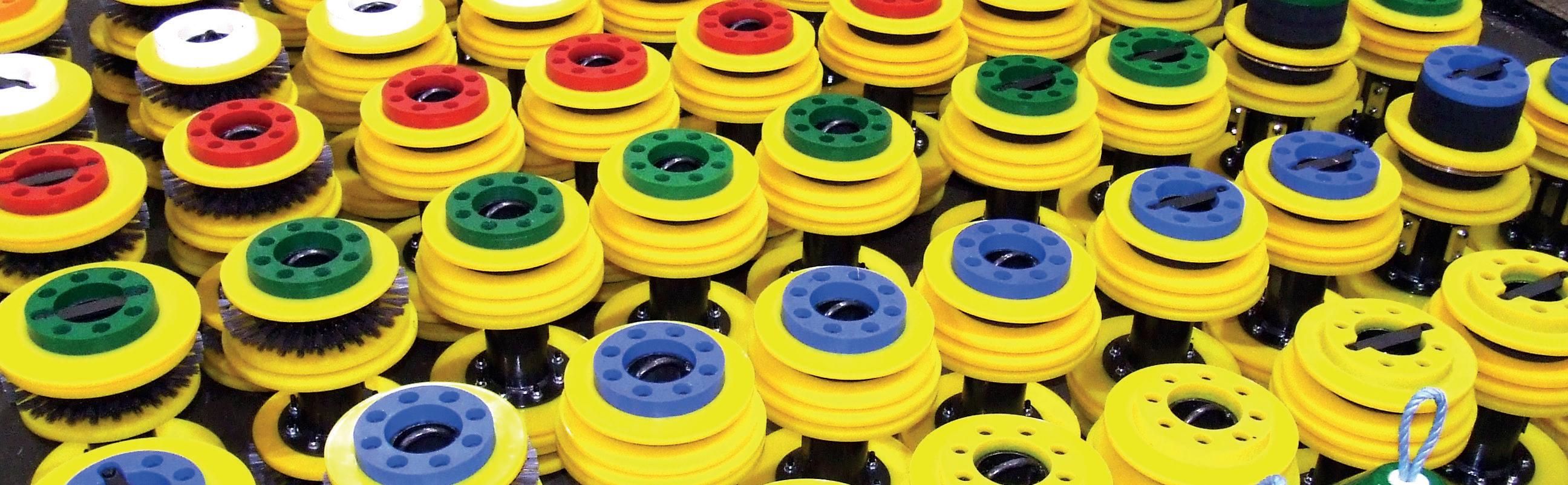
Custom pigs for operational maintenance or pre-inspection cleaning Propipe Limited Queens Meadow Business Park, Hartlepool, England TS25 5TE T: +44 (0)1429 872 927 E: groupsales@propipe.co.uk Propipe North America 302 Bluewater Road, Unit 2 Bedford, Nova Scotia B4B 1J6 T: (902) 417 5075 E: sales@propipenorthamerica.com propipe.co.uk LinkedIn
PIPELINE
sidebooms.com I 918-858-4201
• Propipe provides a suite of services to ensure a successful project including full pipeline review, cleaning pigs and Trident SMART gauge. • Propipe pigs all designed pipelinespecific for best performance. • Trident pig tracking and APEX AGM plus SMART Gauge and Datalogging for full data assessment. SMARTER
CLEANING
maintenance of pipelines where modern systems are increasingly operating in more challenging conditions.
“As such, the market demanded more advanced inspection technologies that could meet the challenges of more complex pipeline designs and new, unencountered pipeline conditions.”
In operation on sites across the Americas, Australia, Europe, the Middle East and West Africa, Discovery has successfully gathered over tens of thousands of scans of valuable data, helping operators refine and improve the efficiency of existing pipeline models.
In North America, Tracerco’s Discovery technology has been deployed to inspect over 100 pipelines and risers on projects across the region. The business has seen an increase in demand – and indeed sales – for its superior technology, particularly across the North America region.
Data-driven insights
By gathering real-time data on a variety of pipeline integrity issues, including pipeline corrosion, pitting and wall thinning, operators can effectively determine the length of time a pipeline can be extended past its original design life.
This cost-effective approach can eliminate the potential operating costs associated with designing a new section of pipeline, recommissioning, pipeline modification, and the time and risks associated with coating removal/reapplication and long and expensive vessel hire.
Innovative design
And for the market leader in inspection technology, Tracerco prides itself on the principle behind the Discovery Technology, which is in the form of a Computed Tornography (CT) beam passing through a material to measure the density and calculate any defect in the pipeline, all in one single scan.
Combine this with Tracerco’s inbuilt ‘fast scanning’ technology, which reduces overall scan time by up to 80%,
and operators across the globe are benefitting from maximum data capture never before available in the market, and from one single inspection.
Deployment
The diagnostics instrument used to detect wall loss, corrosion and buildup such as hydrate, sand, asphaltene, scale or wax can be deployed on piggable and unpiggable pipelines, online, without any interruption to production or the need for pipeline modifications.
The technology can be deployed very quickly using an ROV and simply clamped onto the pipe with real-time communications, allowing for instant assessment of a pipeline’s conditions.
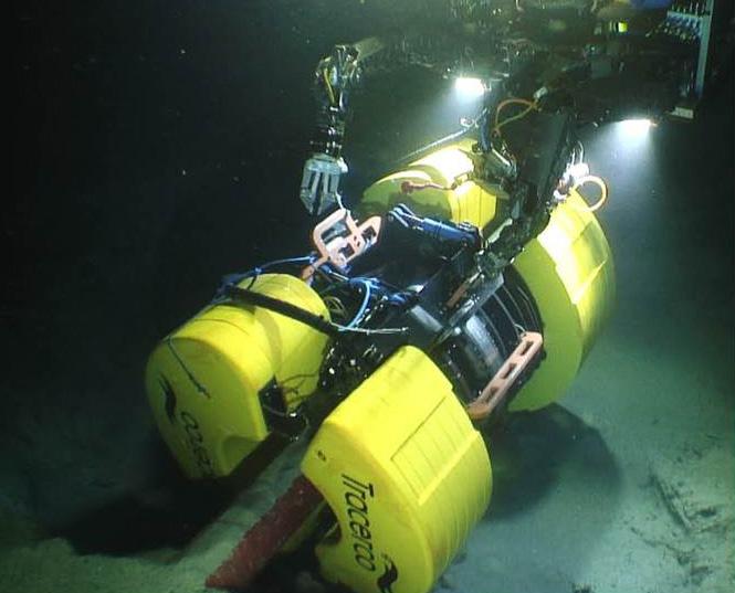
Different versions are available based on pipe diameter and depth of deployment, and all are fully marinised. Unlike alternative technologies such as ultrasonic and pulsed eddy current, using Discovery eliminates the expense and risk of damaging pipelines on coating removal or reapplication.
“The fact that the technology is so easy to deploy,” Jim explains, “is another real advantage and big plus point for operators. Inspection and testing can be done with absolutely zero impact on production – meaning no downtime at all – which is obviously invaluable to operators, enabling them to carry on as normal and gather real-time data to provide the insight they need to make better decisions about their operations.”
Further development
The company is very committed to research and development of its innovative technology suite. As such, the Discovery technology continues to be developed with the advent of fast screening, baselines scans and fatigue analysis. Most recently, developments to the technology have provided more in-depth characterisation of blockages such as asphaltenes, sand, hydrate and wax.
Tracerco prides itself on understanding the real needs and challenges faced by operators in order to enhance its technology, with the greatest engineering minds across the globe collaborating to develop best-in-class solutions that are continually being advanced.
Conclusion
As technology has progressed at a rapid rate, the industry has been very receptive in adopting solutions that allow them to operate more reliably, efficiently and in the safest manner possible, Jim explains.
“Data is absolutely key for owner operators to make insightful decisions when it comes to extending an assets life,” Jim said, “And Discovery is a superior single source tooling technology providing uniformed and streamlined results. Engaging with Tracerco, or technology companies alike, at the very early stages of life extension planning will underpin the success of owner operators prolonging their assets.”
48 World Pipelines / DECEMBER 2022
Figure 2. Tracerco’s Discovery technology on a pipe.
rom operator training to machine design standards, much care across the pipeline industry goes into ensuring the jobsite is as safe as possible. For material handling tasks in particular, a significant safety challenge revolves around utilising the proper equipment depending on the size, shape, weight or quantity of the items being moved.
Equipment manufacturers have developed several solutions to best fit a given operating environment or application. However, there are certain segments of the industry that occasionally rely on a machine because of its versatility, even though purpose-built options exist.
Moving pipe
One such example is handling heavy pipe, whether moving loads around stockyards or placing materials during construction in the field.
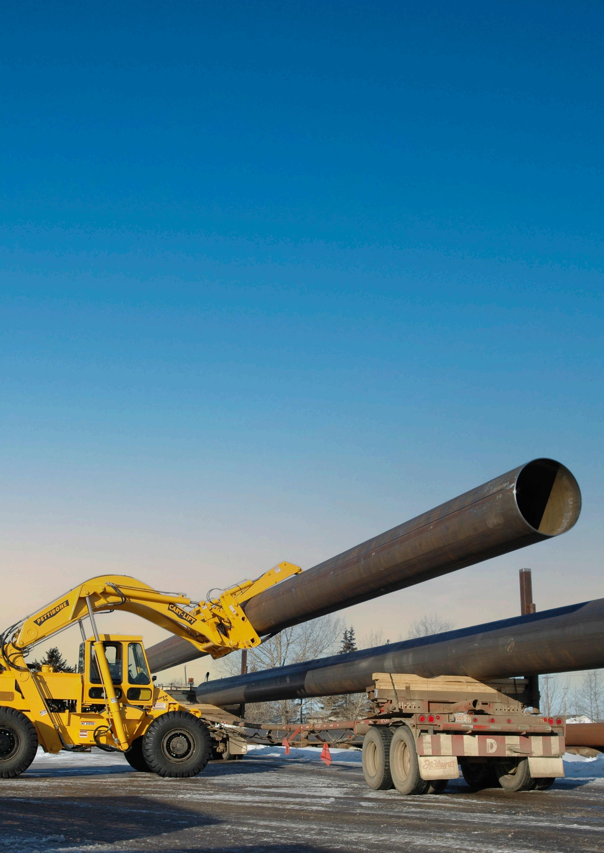
Material handling personnel have commonly relied on wheel loaders for this work, equipping them with fork and baler attachments for lifting pipe. Wheel loaders are known for their versatility, but what’s sometimes forgotten is that a wheel loader is primarily designed to move dirt; users have to compromise on certain performance characteristics when using it for a secondary handling function.
Figure
Meanwhile, there are dedicated pieces of equipment, such as rough terrain forklifts, that are engineered specifically for material handling applications like lifting and placing pipe. These purpose-built machines offer a number of design features that help accomplish the task in a safer and more efficient manner.
Clear visibility
The length of a pipe is almost always greater than the width of the machine carrying it. This makes them awkward items to move, since operators are automatically put into a situation where the loaded materials fall outside the footprint of the vehicle they are driving. In order to manoeuvre safely and avoid collisions or mishaps, it becomes imperative to maximise visibility around the vehicle.
Whether moving pipe through stockyard aisleways or handling it on a jobsite, transporting the load generally requires the machine to be driven while its load is lifted up in the air. With a wheel loader, operators experience obstructed visibility under these circumstances, since the vehicle’s lift arms are positioned directly in front of the windshield.
Mitch Fedie, Pettibone/Traverse Lift LLC, USA, discusses how purpose-built machines for handling heavy pipe create a safer operating experience.
49
1. Purpose-built pipe handlers offer several performance features to do the job in a safer and more efficient manner.
On dedicated pipe-moving vehicles, such as the Pettibone Cary-Lift, the machine is engineered to take this factor into account. Instead of being mounted at the front, overhead lift arms are mounted behind the operator cab. When lifting, transporting or placing loads, this overhead arm design gives the operator full forward visibility with no obstruction, making it far easier to place pipe with precision.
Rear visibility is also important. Rear-view cameras are now commonly standard on such machines. High output LED lighting is another improvement. By better illuminating the jobsite, these lights naturally create a safer work environment.
Stable turns
Stability is another major safety consideration when handling pipe. Operators must be aware of circumstances that can affect the stability of a loaded vehicle, including speed, grade, and ground conditions. Weight distribution, suspension,
wheelbase and tyres can also influence a vehicle’s resistance to tipping, even during routine use.
The level of stability can depend on the vehicle’s intended function vs its actual jobsite application. Wheel loaders, for instance, feature articulated steering that is not conducive to carrying heavy loads while making a turn.
A wheel loader can lose up to 50% of its rated load capacity when turning. Because of this, drivers may have to resort to multiple-point turns, moving forward and back as necessary to complete sharper turns.
Unfortunately, not all operators realise that the physical dynamics of a loader are constantly changing when manoeuvring. One cannot simply rely on the vehicle’s specification data without making proper adjustments based on speed, load, or turning approach. Wheel loaders do tip over, and both the operator and bystanders could be in danger when that happens.
Unlike forward reaching loaders with an articulating joint, the Cary-Lift has a solid steel frame design that provides the ability to take full loads into sharp turns without sacrificing load capacity or stability. The machine also has a shorter wheelbase that allows for tighter turning. A wider stance for the lift arms is another feature of similar rough terrain forklifts, providing additional stability when carrying long pipe.
Some stockyards might rely on traditional straight mast forklifts, but these machines are designed to operate on smooth, graded work surfaces, and aren’t capable of going into rough terrain applications. Using an all-terrain, 4-wheel drive machine is a basic necessity when driving along a pipeline construction project.
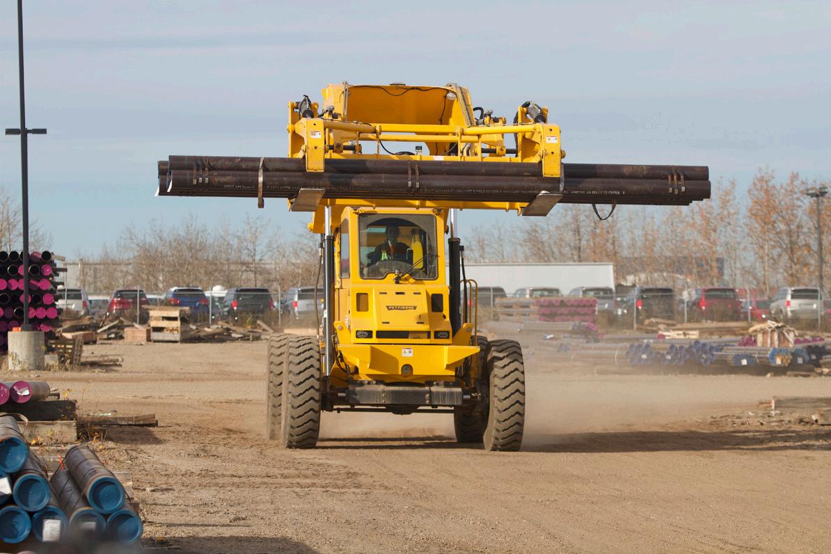
Another feature offered on some machines to enhance stability is hydraulic frame sway control. Vehicles with this capability can level the lifting frame to a certain degree in either direction. This levelling action compensates for the irregularities of uneven terrain.
Safe controls
Equipment manufacturers have implemented smarter operating stations to help drivers work more safely. Many material handlers use joysticks to provide intuitive fingertip control of the hydraulics for simultaneous lifting, tilting and reaching. Ergonomics have also improved to reduce fatigue.
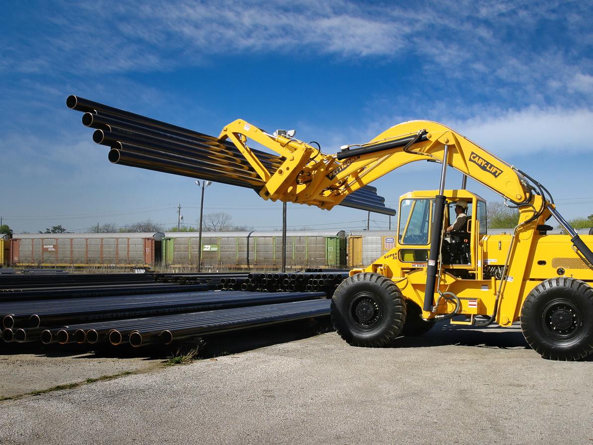
A less obvious factor in the safety aspect of operating any material handling machine is proper maintenance. Though maintenance is ultimately the responsibility of the operator or service technician, manufacturers have helped the cause by making the locations for lubrication and other service tasks more accessible.
Pipeline professionals are highly respectful of safety factors and do excellent work to keep jobsites safe. Manufacturers of heavy lifting vehicles are also doing their part to provide purpose-built equipment that prioritises operational safety.
Figure 2. A loader with a solid steel frame allows for more stable load handling than a machine with an articulating joint.
50 World Pipelines / DECEMBER 2022
Figure 3. The overhead lift arm design of the Pettibone Cary-Lift provides unobstructed front visibility for the operator.
ube and pipe fabricators have been improving quality and reducing scrap with non-destructive testing (NDT) for many years using traditional methods – eddy current testing (ECT) and ultrasonic testing (UT). As powerful as these traditional NDT methods are in testing formed and welded tubes and pipes for defects and discontinuities, they do present several challenges such as complexity in setup, sensitivity to external conditions, and requiring multiple probes to obtain reliable data. ECT and UT methods are unable to detect or classify certain weld defects that are critical to the integrity and quality of tubes and pipes.
A solution to the shortcomings of traditional NDT methods is the introduction of laser-based non-destructive inspection (NDI) of the weld bead on formed and welded tube and pipes. With advancements in machine vision technology, laser-based NDI can be used to find specific weld defects related to the surface profile
 Cameron Serles, President, Xiris Automation Inc., Canada, explores detecting critical defects of welded tube and pipe.
51
of a weld, resulting in improved quality assurance and process control.
The WI-2200/3000 by Xiris Automation Inc. is an NDI system that uses laser triangulation and a camera offset to the axis of the laser plane to measure variations in the surface of a weld bead. The system makes several measurements that can be used to monitor and enhance the productivity of tube mills. These measurements are based on the differences between the actual laser profile line seen by the camera, and the ideal mathematical profile which is determined by the tube diameter.
By knowing the position of the actual laser profile, the ideal profile, and the size of the pixels in the image, the WI-2200/3000 Weld Inspection System can calculate various profile defects that are often missed by ECT and UT methods.
Various weld profile defect measurements
Mismatch
The mismatch defect measurement compares the two edges on either side of the weld to see if there is uneven joining of the two edges of the tube material as they come together at the weld point. Mismatch could be a result of incorrect forming setup, edge break issues, or twisting of the strip feed into the rollers. This defect may result in significant thinning of one side of the tube wall after ‘scarfing’ or grinding the weld area, compromising the tube quality. Even in situations where no scarfing or grinding occurs, the diameter of the welded tube in the vicinity of the welded bead area may be larger or smaller than the ideal tube diameter, possibly causing failure during corrugation, further forming, or bending of such tubes. It is important to know the absolute value of the mismatch to determine how much offset exists between each side of the weld.
Freeze line
Freeze line is a measurement from the lowest point of any contour on the surface of the weld bead to the surface of the parent material, as defined by the ideal circle scribed by the walls of material beyond the weld zone (Figure 2). If the freeze line goes below a predefined height, then it is considered a defect of the weld bead. Freeze line defects are a result of incomplete fusion of the faces of the parent material that occur when not enough power or heat is put into the weld. The result is a potentially cold-welded joint, which manifests itself as a line or seam extending from the top surface of the weld down into the welded area, in the shape of a sharp valley. The defect often indicates major metallurgical or structural problems in a weld, such as cold welding, inclusions, or improper forming. It can very often be a point of major failure of a weld in high-stress applications, as the freeze line can act as a crack initiator into the welded material.
Undercut
Undercutting in welding is a weld defect usually characterised by a groove formation at the weld toe as it is an underfill condition or non-welded area along one or both sides of the bead, characterised by one very steep slope, and the other side more gradual. Undercutting in welding may occur because of high travel speed, poor welding techniques, excessive heat, or too high amperage. It can also occur if the welding torch (laser, TIG or plasma) is not centered over the seam formed by the two sides of the tube material coming together. It looks and behaves like a crack along the bead edge, creating a stress riser or weak point on the tube crosssection and a potential site for failure.
Left and right slope angles
The left and right slope angles are measured in degrees at either edge of the weld bead, and represent the angle subtended by a line that follows the contour of
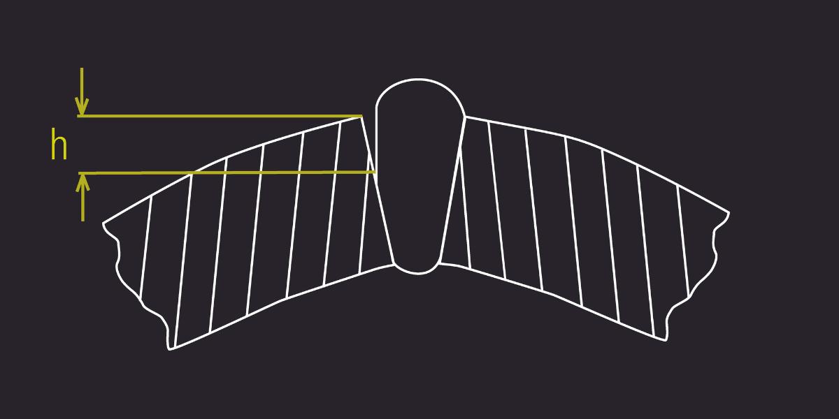

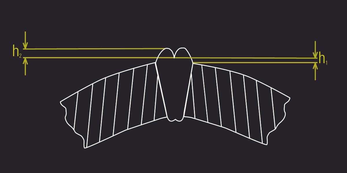 Figure 3. Undercut.
Figure 2. Freeze line.
Figure 3. Undercut.
Figure 2. Freeze line.
52 World Pipelines / DECEMBER 2022
Figure 1. Mismatch.
Worldwide Coverage

Register for free at: www.worldpipelines.com


A global industry requires a global publication
the weld bead against a horizontal line. Note that it is important to measure both the left and right slope angles separately, as the shape of the parent material could be asymmetric. Also referred to as the toe angle, it can indicate the strength of the weld and the correct forming of the parent material of the tube during the creation of the weld, particularly on an ERW/HF process. A larger or smaller than-normal slope angle could be an indication of a forming problem. If the forming pressure is too high, then the slope angle would be steeper as more weld material gets squeezed out of the weld zone. If the forming pressure is too low, then the angle measure becomes larger. Asymmetries of the rolling process on the tube mill can cause the slope angles to be different on either side of the weld bead.
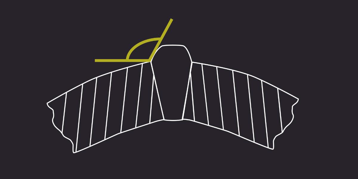
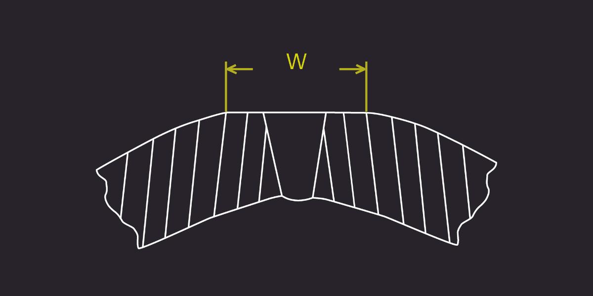
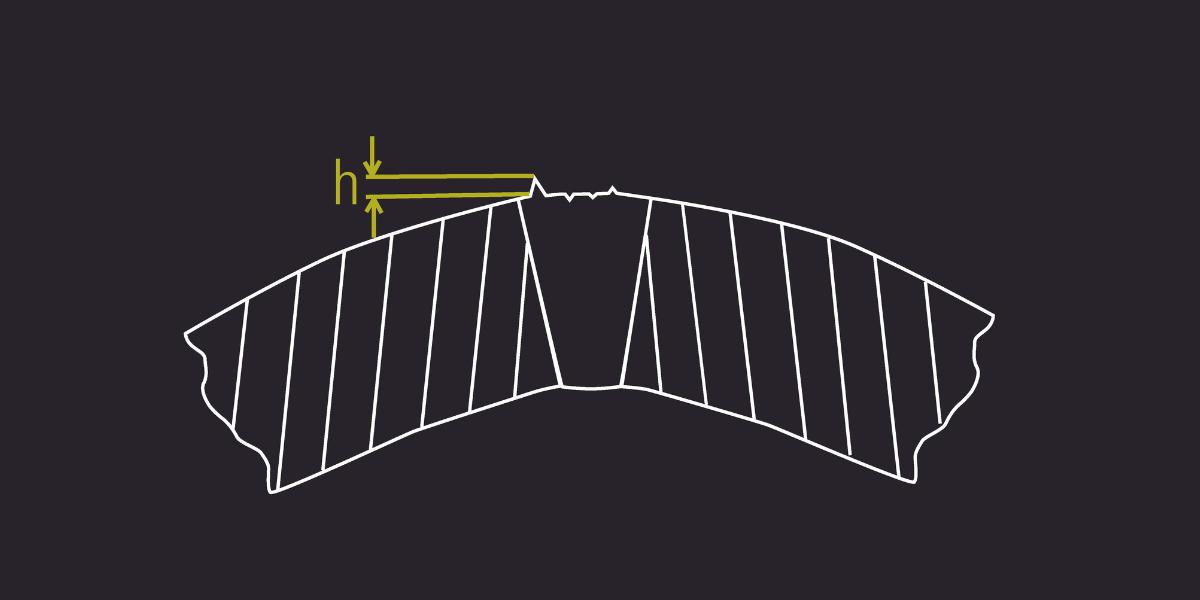
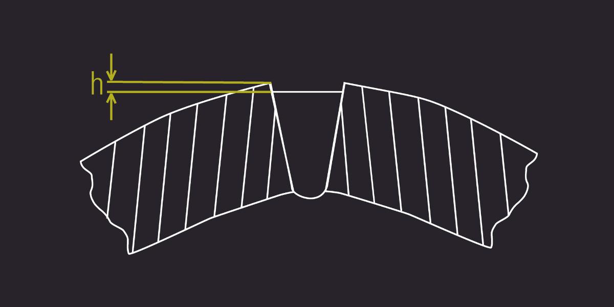
Scarf width
A scarf width measurement can be taken after the scarfing tool to measure the size of the flat portion of the tube where the scarf has occurred. The scarf width is measured post scarf and can grow larger than desired if the scarf tool has been setup to remove too much material. Alternatively, a larger than desired scarf width can occur when the support rollers used to hold the tube get dirty with metal chips from the scarfing material, and cause the tube to lift as the debris gets caught between the roller and the tube. When this happens, the tube gets pushed into the scarfing tool, removing additional material.
Scarf depth
An alternative to measuring the width of the scarf cut is to measure the depth of the scarf cut. In this case, the scarf tool may be less than or equal to the maximum width of the weld bead and may cut too far into the weld bead, causing the scarfed surface to be below the surface of the edges of the parent material. Like the scarf width defect, this defect can occur if the scarf tool has not been properly setup to remove the right amount of weld bead, or if the tube height unintentionally bounces around and the tube gets pushed into the scarfing tool, causing the tool to cut deeper than normal. When there is debris on a supporting roller under the tube, the tube could be lifted into the scarf tool on a periodic or random basis, which can be very difficult to detect with any other type of inspection process.
Scarf tool defect
A scarf tool will eventually wear and may chip or break over time. When this happens, the effectiveness of the scarfing process is reduced as the resulting scarf surface changes from a clean, smooth cut to a rough surface with ridges left behind by the damaged scarf tool. The scarf tool defect measurement will measure the largest offset from a nominal surface as a way of indicating how rough the scarfed surface of the tools is.
Figure 7. Scarf tool defect.
Figure 6. Scarf depth.
Figure 5. Scarf width.
54 World Pipelines / DECEMBER 2022
Figure 4. Left and right slope angles.
For over 70 years, PLCA Members have provided the highest quality construction and maintenance services to U.S. owner/operators with an industry-leading focus on safety, quality, efficiency, training, environmental compliance, and community support.
Join us for the PLCA's 75th Annual Convention at the Grand Hyatt Kauai February 7-11, 2023 Visit www.plca.org to learn more
Pipe Line Contractors Association 3100 Clarendon Blvd., Ste. 620 Arlington, VA 22201
Proud to be Pipeliners www.plca.org
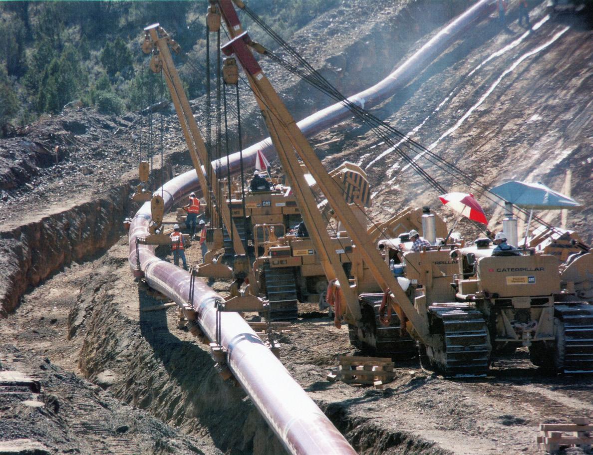
MATERIAL.indd 1 19/12/2019 09:59
Process controls and integration
When one of the defect warning or failure limits is breached, an audio and/or light tower signal can be generated. The generated signal can be sent to an external defect marking system (paint or laser) that marks the area of the tube where the error occurred so that further inspection, repair, or removal can be performed. Real-time data can be communicated to external devices such as the tube mill PLC via digital outputs, or software-only interface protocols such as OPC-UA. Playback mode allows review of visual data and defect levels with timestamps, so that issues can be diagnosed quickly, and process improvements introduced with minimal delay.
Successful results
Adding a Xiris WI system to your mill provides realtime monitoring for multiple defect conditions, enabling continuous incremental improvements of mill quality and productivity. Many manufacturers of high-quality tubular products for the automotive industry have implemented the Xiris WI-2200/3000 inspection system to help maintain high quality standards when producing thin-walled tubes that meet the strict demands of the automotive industry. These manufacturers, like all, realise several benefits to implementing the system on their mills.
First, they develop a faster setup after changeover. Once a mill has been setup for a new product, and the material has started to run production, an operator will monitor the tube quality with the WI-2200/3000 inspection system for various measurement metrics, and adjust several parameters until the measurements fall within specification. As a result, setup time can be reduced significantly while producing less scrap.
A second benefit is being able to detect wear on roller tools. Many manufacturers notice how certain measurements such as deflection continue to vary on a cyclical basis with the amount of deflection rising and falling periodically, indicating inconsistent tooling. This may be a result of wear on the forming rollers, and be an indicator that the rollers need to be replaced. Manufacturers can monitor the deflection measurement as an indication of when to replace the rollers, helping to reduce scrap or avoid it entirely.
Lastly, many manufacturers benefit from the ability to detect poor adjustments in the setup of the forming and handling equipment. If the tube rolls too far in one direction, the seam can move out of the path of the weld head or scarf process, potentially creating scrap material. The WI-2200/3000 inspection system allows operators to monitor if the tube is twisting back and forth, prompting them to adjust the forming and handling equipment accordingly.
Once implemented, a Xiris WI-2200/3000 Weld Inspection System can detect defects and help perform better monitoring to keep a tube mill in process control. As a result, manufacturers can realise cost savings from reduced final scrap, faster product setup times, less downtime and fewer customer returns.
DIRECTORY
Page
23
44
24
ADVERTISERS’
Advertiser
3X Engineering OFC,
AGRU
Allan Edwards OBC BAUMA 31 Böhmer GmbH
CRC-Evans 4 Darby 41 EDI 43 Girard Industries 44 IPLOCA 12 MetriCorr 18 - 19 Midwestern 47
27 Pipeline Coating 2023 2 Pipe Line Contractors Association 55 Pipeline Inspection Company 53 Propipe 47 Qapqa 35 ROSEN IFC
S.p.A, bound insert Stark Solutions 15 Stats Group 11 T.D. Williamson 17 Winn & Coales International 7 World Pipelines 53
Palladian Energy Podcast IBC Pigs Unlimited International LLC
SCAIP


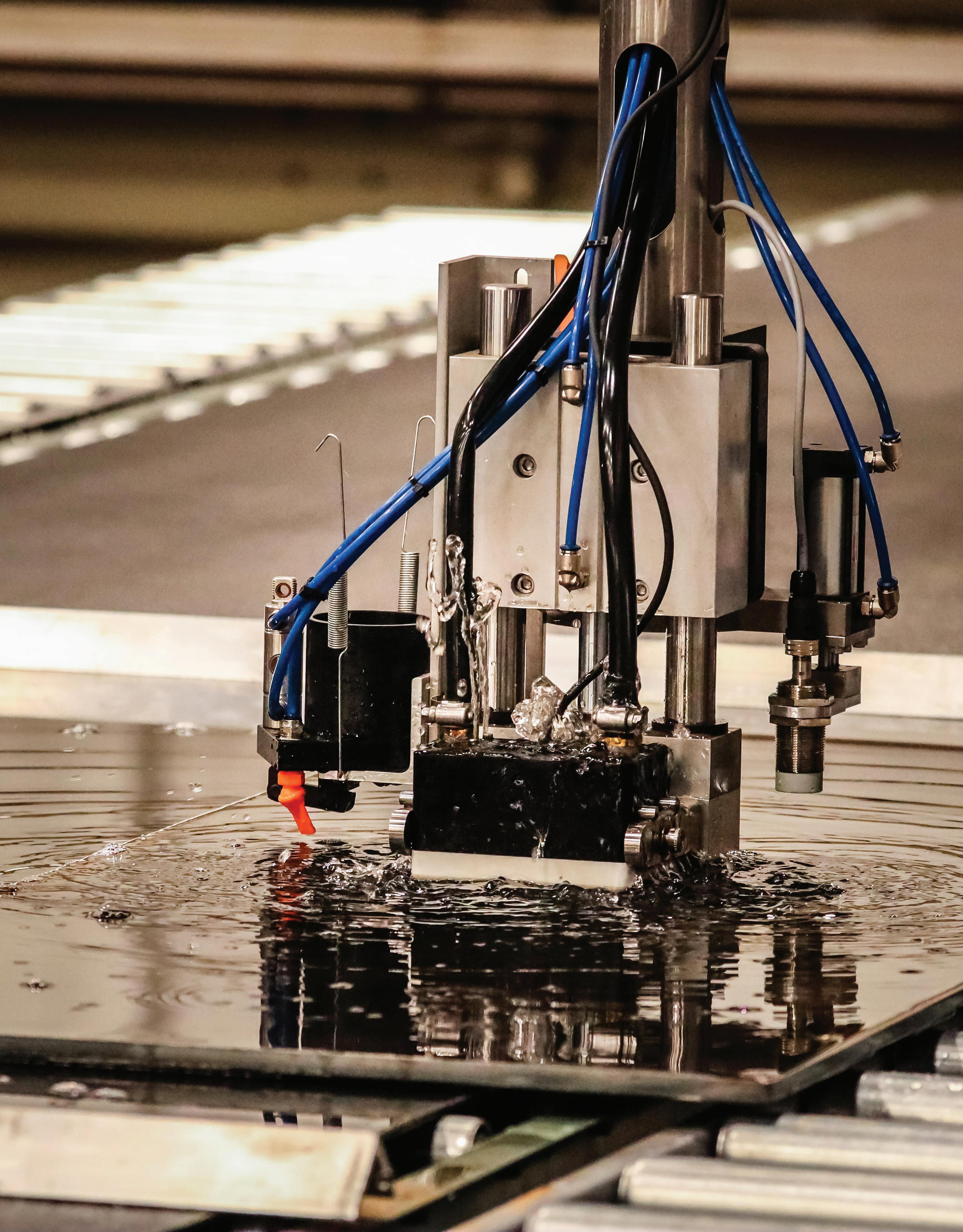

VISUAL QUALITY INSPECTION ALONE WON’T CUT IT. KNOW YOUR STEEL SLEEVE INSIDE AND OUT… WITH OUR PHASED ARRAY UT MACHINE. GET THE DETAILS ON ALLAN EDWARDS 100% ULTRASONIC TESTING. 6468 N Yale Ave. Tulsa, OK 74117 // allanedwards.com // 918.583.7184 DON’T DO REPAIRS WITHOUT IT.