
9 minute read
A journey into pipeline monitoring


Ken Maxfield (USA) and Mark Briell (Canada), KMAX Inspection LLC, unravel the many challenges of inspecting ‘unpiggable’ small diameter pipelines.
ntelligent pigs have come a long way since their introduction more than half a century ago. The first commercial ‘smart pig’ – utilising MFL technology – had few sensors, no odometer wheel, only collected data on the bottom quadrant of the pipe, and recorded information on reel-to-reel tape.
Today’s advancements in microprocessor computational power, memory density, sensor technology, engineering design and modelling software, as well as rare earth magnetics, have allowed the evolution of an MFL inline inspection (ILI) system that can detect and locate far more than just metal loss.
Traditionally, these ILI tool advancements have not been applied to small diameter tools due to space constraints and pipeline geometry. As such, many small diameter pipelines have been labeled as ‘unpiggable’ and have never had an ILI.
Moreover, most small diameter pipelines were designed and built without consideration for ILI tool passage. Even so, those that were built for ILI tool passage may have fittings installed, or have operational conditions that do not allow for an ILI tool to inspect the pipeline.
Here is a partial list of pipeline features that have caused these small diameter pipelines to be classified as ‘unpiggable’: ) Short radius elbows.
) Mitred bends.
) Heavy wall tees.
) Bore restrictions.
) Back-to-back bends.
) Unbarred tees, Y connections, offtakes, laterals and deadlegs.
) Vertical pipe.
) Thick or thin pipe wall.
) Lack of launcher/receiver facilities.
Arguably, one could modify a pipeline to be made ‘piggable’, but this would require an interruption of service to modify and/or remove any ‘unpiggable’ features; a task which would invariably prove to be expensive, time consuming, and in some cases impossible due to high costs, technical feasibility, risk factors and a host of other considerations.
KMAX Inspection has made significant advancements that has allowed many of these lines classified as ‘unpiggable’ to be inspected with MFL ILI technology without modification to the pipeline, with over 59% of the MFL ILI inspections performed by KMAX having been first time ILI inspections.
And yet, the biggest challenge remains that most wall thickness changes happen on the inside of the pipeline, creating significant bore restrictions when measured as a percentage of pipe diameter. Thus, the risk of an ILI tool becoming lodged in a small diameter pipeline is considerably higher than an ILI tool becoming lodged in a larger-diameter pipeline.
Before undertaking an inspection of a small diameter pipeline, some upfront work is necessary to determine if an ILI tool can successfully navigate the pipeline. Here are some pipeline features that need to be evaluated: Pipe wall thickness The maximum wallthickness needs to be determined. Small diameter pipe is remarkably strong.
For example, a 3 in., schedule 40 wall, X42 grade pipe has a burst pressure of 357.42 bar (5184 psi). Even so, some 3 in. and 4 in. pipelines have schedule 80 or thicker pipe wall installed. MFL technology in 3 in. and 4 in. sizes can magnetise schedule 40 pipe, but because of the physical restrictions on tool size are not able to magnetically saturate thicker wall pipe. Older pipelines rarely have accurate and complete as-built records and repair documentation. Thus, the easiest way to obtain a sample of WT’s is to take measurements of all above-ground piping using a handheld ultrasonic wall-thickness measuring device. If feasible, the best and most complete way to obtain wall-thickness information is to run a geometry tool. Elbows If a pipeline contains forged elbows, the bend radius and wall-thickness of the elbow fitting needs to be determined. Bear in mind, small diameter forged elbows have a radius that is calculated on the nominal OD of the pipe size, and not the actual OD of the pipe. For example, a 3 in. pipe has an OD of 3.5 in., but the elbow radius Table 1. Elbow radius is is calculated using the nominal OD of 3 in. This pattern calculated using the nominal holds for all pipe sizes below 14 in. If we applied the same diameter of the pipe instead formula for 3 in. elbows as we did for 14 in. elbows, a 3 in. of the actual diameter for all pipe diameters below 14 in. 1.5D elbow is really a 1.29D elbow! If the pipeline contains forged elbows, determine if any Dimension ‘D’ of the elbows are considered back-to-back, or an elbow welded to another elbow. If so, are the back-to-back elbows on the same axis, or different axes? Some new MFL ILI tools can pass back-to-back 1.5D bends in 4 in. and some 1.5D back-to-back bends in 3 in. pipelines. Any backto-back elbows need to be evaluated to make sure an MFL ILI tool can pass the elbow configuration. Another issue we see with elbows in small diameter pipelines is heavy weld penetration between the elbow and straight pipe which can cause a major restriction in the pipeline bore. Tees Tees are very problematic in 3 in. and 4 in. pipelines as they are not inspected for bore diameter before being installed, and in our experience many heavy wall tees are used in small-bore pipelines. If you are designing small diameter pipelines, do not select fittings that are a higher schedule of wall thickness than the nominal wall thickness of the pipeline, and remember, there is no minimum bore requirements for fittings. ASME B16.9 states “Bore diameters away from the ends are not specified. If special flow path requirements are needed, the bore dimensions shall be specified by the purchaser”. We recently inspected a 3 in. pipeline for which a new receiver was fabricated for the upcoming inspection. A tee was installed in the new trap that had a wall thickness of 22.3 mm (0.878 in.). This represented a bore restriction of more than 40% when compared to the outer diameter of the pipe. Consequently, the tee had to be replaced prior to conducting the MFL ILI inspection of the pipeline.
Dimension ‘A’ (for a 1.5 dia. elbow)
3.5 in. 4.5 in. (3 in. x 1.5)
4.5 in. 6 in. (4 in. x 1.5)
6.625 in. 9 in. (6 in. x 1.5)
12.75 in. 18 in. (12 in. x 1.5)
14 in. 21 in. (14 in. x 1.5)
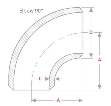
Figure 1. Elbow radius is calculated using the nominal diameter of the pipe instead of the actual diameter for all pipe diameters below 14 in.

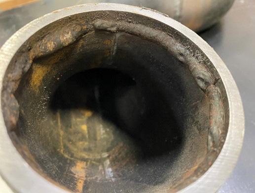
Figure 2. Elbow with heavy weld penetration.
Minimum bore For safe passage of an inspection tool, the minimum bore of the pipeline must be determined. This can be accomplished by running a gauge plate pig or a geometry tool through the pipeline. Minimum bore in the pipeline is usually the result of heavy wall fittings, elbows, dents and/ or heavy weld penetration. Magnet design and strength along with other technical advances have allowed new MFL ILI tools to be built that will pass through significant bore restrictions.
Traps If the pipeline has a launcher and receiver, it might require modification for the ILI tool. At the launcher, the most important dimension is the length of the oversized pipe. The oversized section of the launcher must be longer than the ILI tool, unless there is a way to pull the ILI tool into the nominal pipe of the launcher. At the receiver, the most important dimension is the length of nominal size pipe after the receiver valve. Most modern ILI tools drive from the front, so the length of nominal pipe must be longer than the ILI tool to be able to pull the tool past the receiver valve.
Pipeline product and speed during the ILI inspection The pipeline must be evaluated to determine if the product and flow rate are compatible with the chosen ILI tool. If not, the pipeline might have to be evacuated and another product used to propel the ILI tool. For example, a low-pressure gas line that does not have enough pressure or flow to run an MFL tool, might have to have nitrogen or liquid introduced into the pipeline to create enough pressure and flow to run the MFL tool.
Surging can present significant challenges when running small diameter tools in gas pipelines. Surging occurs due to internal bore restrictions caused by wall thickness changes and fittings. Surging when running an ILI tool in a compressible medium such as gas occurs when the differential pressure needed to propel the ILI tool increases due to a bore restriction or bend. Pressure builds behind the ILI tool until the required differential pressure has been built to propel the ILI tool past the bore restriction. Once past the bore restriction, the tool now experiences a higher differential pressure than was present or necessary before the bore restriction. The tool will now accelerate to a high speed due to the higher differential pressure. The tool speed will accelerate rapidly and then deaccelerate as the differential pressure is reduced.
Dents Dents in the pipeline are often caused during the construction of the pipeline, by equipment operating near the pipeline (third-party damage), or by ground movement. A large dent may cause an ILI tool to become stuck in the pipeline. The existence of dents in the pipeline should be identified by running a gauge plate pig, or an ILI geometry tool.
Internal debris The pipeline should be free and clear of internal debris, ferrous material and paraffin. If the pipeline has never had a magnetic cleaning pig run through the pipeline, plan on running this type of cleaning tool to remove ferrous material that could be in the pipeline from construction or internal corrosion. MFL ILI tools contain strong magnets that will attract ferrous debris that will have a negative impact on the sensor readings.
Any pigging programme for a small diameter pipeline should be very conservative if the pipeline has never been pigged. Start by running foam pigs through the pipeline. Once a foam pig can be run through the pipeline without damage, run a polyurethane cast pig through the pipeline. If all goes well, run a gauge plate pig through the pipeline. Once a gauge plate pig is run through the pipeline, you might consider running a geometry tool through the line to determine wall thickness ranges if they are not known. With all this information, you should be able to determine if you can now run an MFL ILI tool through your line.
Summary Small diameter pipelines are difficult to inspect with ILI tools, and as such many have never been pigged. With the advancement of magnet strength, magnet design, and electronics, it is now possible to inspect some of these previously ‘unpiggable’ pipelines with MFL ILI technology.
Determining the wall thickness of pipe and fittings in a small diameter pipeline are critical to determine if the pipeline segment is a candidate for an MFL ILI inspection.
Lastly, cleaning is vital to a successful ILI, especially if the line has never had a magnetic cleaning pig or MFL inspection. Ferrous debris can remain inside a pipe even after running a foam or cup pig through the pipeline segment, thus compromising data quality.


