16 minute read
Inspection tools: a case study


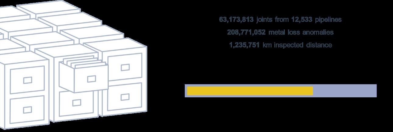
Figure 3. The Integrity Data Warehouse (IDW) contains over 200 000 000 metal loss anomalies.

Figure 4. The IDW features metadata from ILI listings and relevant sources.
We therefore tend to know relatively little about the true condition of uninspected pipelines, particularly when they are at the bottom of the ocean or buried underground.
This is an example of how data science can bring real value: by learning from the condition of similar pipelines that have been inspected in the past, we can begin to understand the different variables that predict pipeline threats and develop models to predict the condition of uninspected pipelines.
We can observe trends in inspected pipelines and apply what we have learned to uninspected pipelines.
This technique can be applied to a number of different pipeline threats, but initial work has focused heavily on the endemic and ever-present threat of external corrosion. These models serve as ‘ECDA-lite’, because they do not require the same volume of target pipeline data, and because they can be very useful when comparing pipelines within a network. They can provide an operator with a clear ranking of ‘problem pipelines’ in their network (whether unpiggable or not) and focus resources on more-targeted ECDA desk studies. Greater insights also allow operators to adjust inspection intervals or, in the case of some larger companies, the ability to foresee where they need to perform in-field work to optimise logistics and resource planning.
Condition prediction can be conducted on a pipelineby-pipeline basis. However, the benefits multiply when it can be done on a joint-by-joint basis; an approach that produces a far more refined approach to identifying joints in poor condition than other, more-traditional approaches such as direct assessment (ECDA, ICDA, SCCDA, etc.), which are costly and time-consuming because they require excavation and possibly even a temporary reduction of the operating pressure. While direct assessment, unlike ‘virtual ILI’, does provide a real view of the pipeline condition, it is highly dependent on ensuring the correct joints have been excavated. Each joint is typically mutually exclusive; for example, just because one joint is free of a given anomaly type – e.g. corrosion, SCC, etc. – that does not mean a joint a few 100 m away also is not affected by the same anomaly type. Conversely, we cannot assume the entire pipeline is damaged just because one joint is in really bad condition.
Generalisable ML models are useful for predicting condition (from severity to density) at the network, pipeline or joint level, but real value can only be delivered by combining subject-matter expertise from the operator and consultants with high-quality data inputs to improve the models and inform robust validation methods (i.e. ILI). Studies leveraging data science not only provide pipeline owners with useful insights to support their integrity management decisionmaking, they also foster a culture of purposeful data collection and governance. Once data-science principles are adopted and practices aligned with business needs, these capabilities, datasets and insights can be applied to other threat types and other business problems beyond the purely technical.
ROSEN has been advancing this initiative, and partnering with operators, to explore many applications of the IDW, such as: corrosion prediction, external interference hit rate, crack prediction, condition metrics benchmarking and ranking, and corrosion growth rate prediction for uninspected pipelines. Future areas of interest include condition of offshore assets, pipeline movement, bending strain and enhancing ILI anomaly classification.
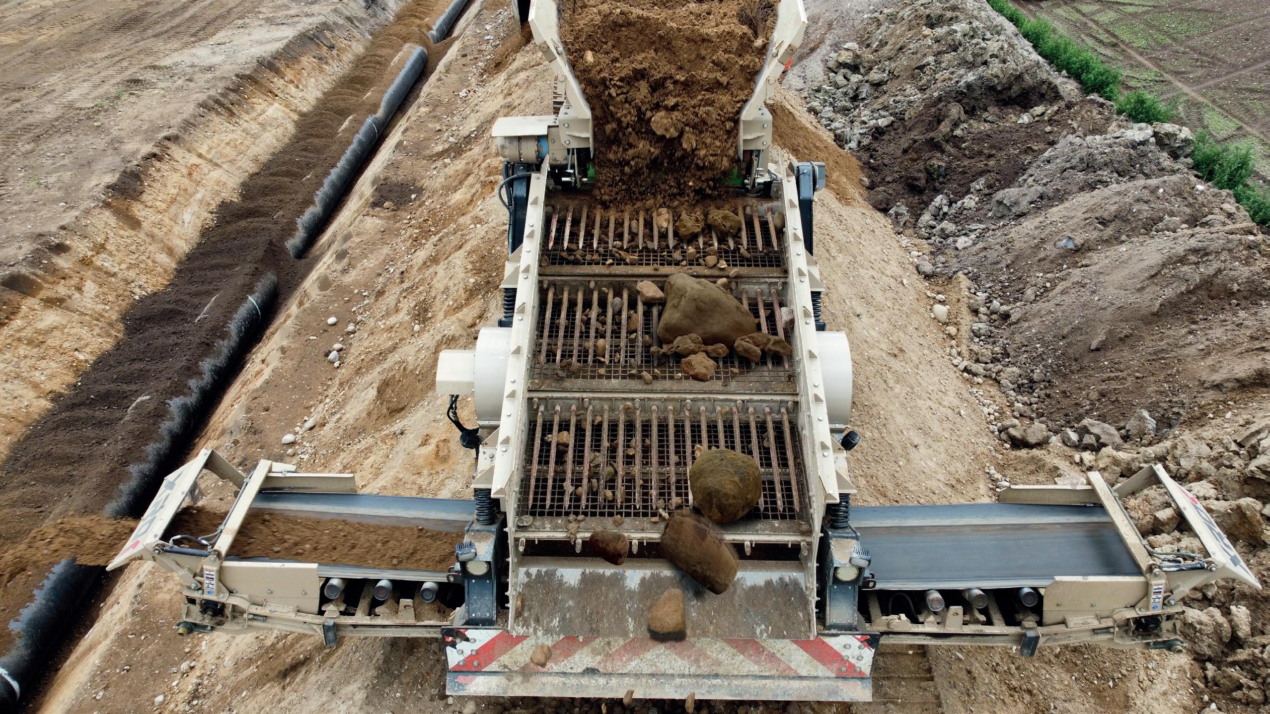
WORLD LEADERS IN PADDING TECHNOLOGY
Over the last six years Xrok Granite 400 pipe padding machines worked on many major and some of the most challenging pipeline projects around the world. Having gained invaluable working experience in the eld plus listening to valuable customer feedback our design team have made cutting edge improvements and upgrades to the current model with some innovative advances to further improve production, versatility and reliability. Some of the major advancements are to the screen box which is the heart of a padding machine, our new improved stepped double deck technology greatly improves both e ciency and performance putting the Granite 400 into a class of its own. Whether deployed to the driest of deserts or to the wettest and harshest environments in the World, the new improved Xrok Granite 400's superior performance will outperform and pad more pipe per day than any other machine currently on the market which equals a huge cost saving to the customer. xrok.com
Delta Machinery is the sole distributor for Xrok
Voltstraat 19, 5753 RL Deurne, the Netherlands • T: +31 (0) 888 966 966 • sales@deltamachinery.nl
When you do have to inspect Of course, there will be a few cases where the AI engine and algorithms will not be able to give us all the answers, or will predict such a high-risk pipeline that an inspection is prudent or even necessary. So, when direct or indirect measurement data of an unpiggable pipeline is really needed, an ILI may become unavoidable. How should we approach an ‘unpiggable’ pipeline? This is where a ‘toolbox’ of solutions, approaches, technologies and experiences comes into play. A variety of challenges can be present, but most commonly, multiple challenges exist to make a pipeline truly ‘unpiggable’.
When it comes to assessing a pipeline to determine piggability, three main factors must always be considered: accessibility, negotiability and propulsion.
Accessibility • How do I get the tool into the line? • Launchers and receivers? • Single access only? • Subsea launch?
Negotiability • Any obstacles getting through the line? • Bends? • Diameter variations? • Difficult valves or other installations?
Propulsion • Can the tool be pumped? • Can the tool be pumped, but with constraints and under difficult operational conditions (pressure, temperature, etc.)? • Can the tool be pulled? • Does the tool require its own drive?
As with any ILI, access to the pipeline is critical to provide an insertion/extraction point for the ILI tool. In standard pipelines, this is easily remedied with launchers and receivers, but with challenging lines, small modifications to both the tool and the pipeline itself may be required. In some lines, simply adding rental barrels may be a straightforward fix; others may require a cut into the line – possibly supported by hot tapping to reroute the product – to allow for temporary access. With standardised ILI technology, more conventional methods are needed, but using specialised tools, insertion and extraction can often be performed with just a spool piece tied in with a flange. In order to reduce the need for additional modifications to access points, tool technologies play a significant role. Where unidirectional technologies were once the main technology available, bidirectional tools across various measurement platforms, including magnetic flux leakage (MFL) and ultrasonic wall measurement (UTWM), are readily available on the market. Bidirectional tools allow for the reduction of separate tool insertion and extraction points into a single insertion/extraction point, greatly reducing operational expenditures.
Once one or more access points have been defined, the general pipeline layout needs to be understood in terms of installations such as bends, offtakes, diameter changes and wall thickness transitions. Also critical are geometric features that could impede the passage of an ILI tool. While most such features as 1.5D bends do not typically pose a risk for ILI tools, they may cause fluctuations in tool run behaviour, resulting in degraded data. More significant features, such as external damage or diameter changes, will require more specialised tool technologies. While most installations can be overcome with nonstandard tools, it is critical that close collaboration occurs between the vendor and operator to ensure all the details of the line are understood. This critical step ensures that all risks are fully aligned with all parties, resulting in proper tools being selected along with the corresponding work procedures.
ILI technologies are primarily designed to run with the flow of the product, with each tool having minimum pressure and/ or flow requirements to ensure it will not only pass the line but pass the line with a stable velocity. Industry-wide, most highresolution MFL, caliper and UT technologies can capture data that meets their specifications at velocities of up to ~5 m/sec. While most standard systems operate at flow speeds within this threshold, many operate at lower flow and low pressures. In these instances, without proper usages of low-friction tool technologies, speed excursions, stop-starts, and accelerations and decelerations may occur, causing missing or degraded data in potentially critical areas. Similarly to low-flow pipelines, the tool may experience intermittent speed fluctuations due to excessive tool drag and product bypass across the sealing cups/elements. Vendors who specialise in challenging assets tend to follow a toolbox technology-development approach where, in lieu of designing tools with a specific need to meet a vast market requirement, separate elements are built in order to customdesign a tool for each challenging application. In the case of a low-pressure line, a compact low-friction MFL tool may be built. Or, with a low-flow line, a high-sealing UT tool can be utilised. Or, in the case of a line without product flow, self-propelled
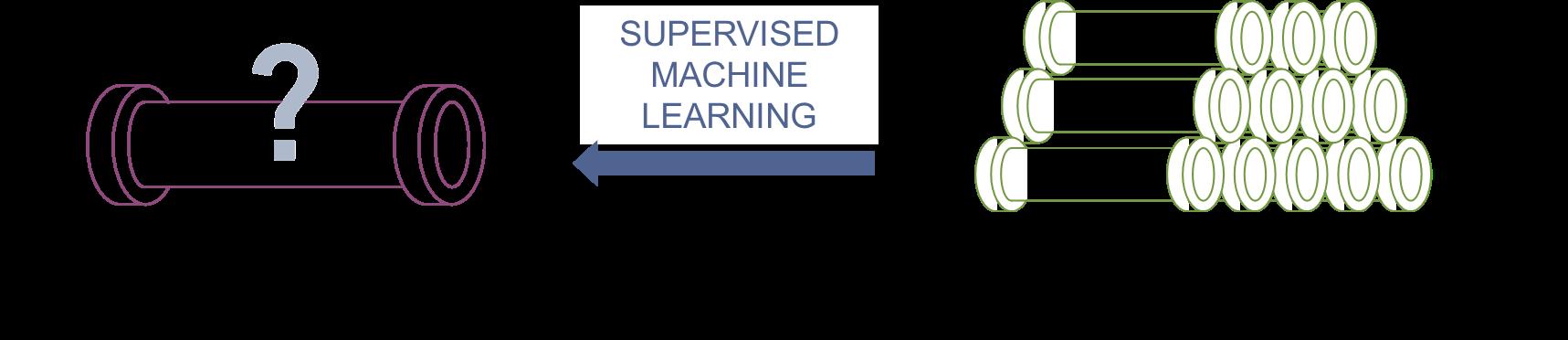
Figure 5. Supervised machine learning for condition prediction.
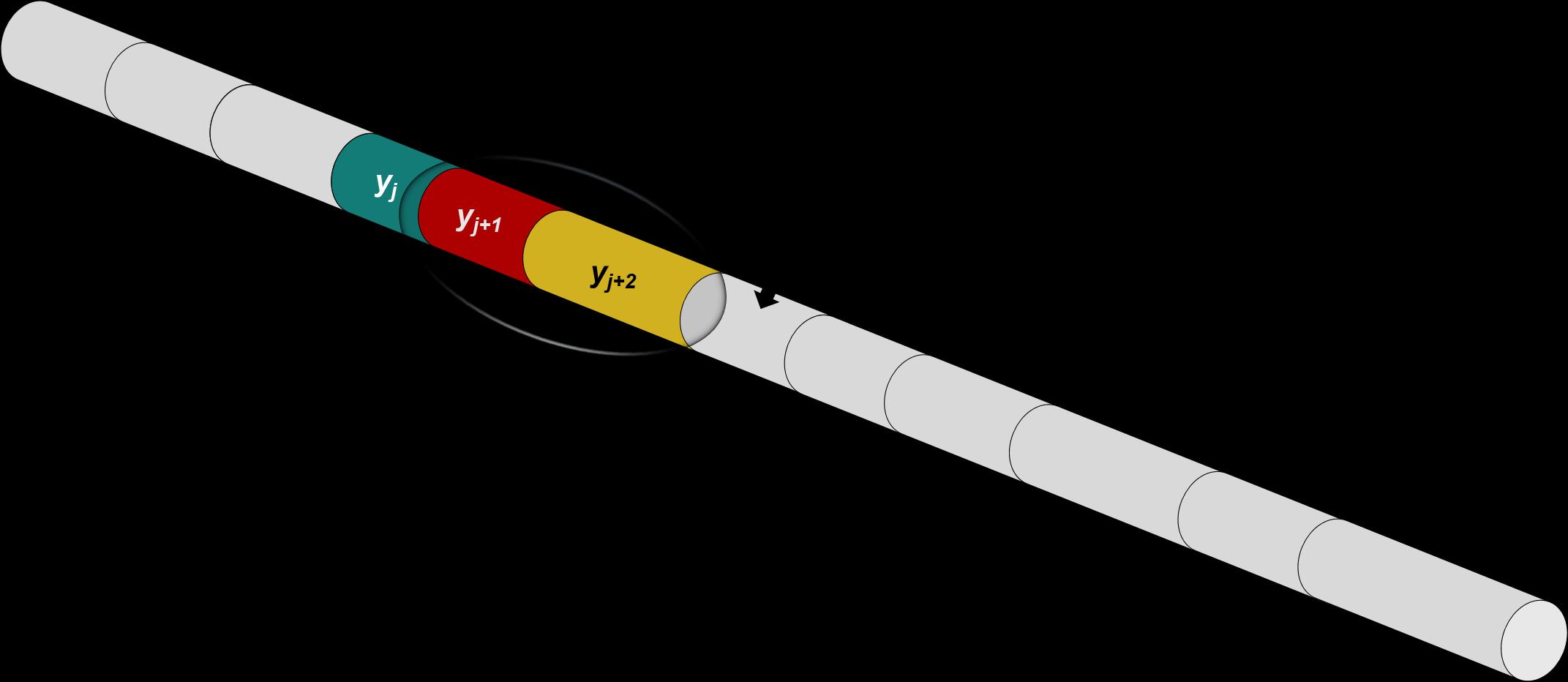
Figure 6. Predictive analytics can help operators to identify low to high-risk joints within a pipeline and prioritise those joints for investigation and mitigation.
drive units can be equipped for use on a variety of measurement technologies.
While indeed not all challenging pipelines have an ‘off-theshelf’ solution, most can be solved with a toolbox approach.
As with any ILI, access to the pipeline is critical to provide an insertion/extraction point for the ILI tool. In standard pipelines, this is easily remedied with launchers and receivers, but with challenging lines, small modifications to both the tool and the pipeline itself may be required. In some lines, simply adding rental barrels may be a straightforward fix; others may require a cut into the line – possibly supported by hot tapping to reroute the product – to allow for temporary access. With standardised ILI technology, more conventional methods are needed, but using specialised tools, insertion and extraction can often be performed with just a spool piece tied in with a flange. In order to reduce the need for additional modifications to access points, tool technologies play a significant role. Where unidirectional technologies were once the main technology available, bidirectional tools across various measurement platforms, including magnetic flux leakage (MFL) and ultrasonic wall measurement (UTWM), are readily available on the market. Bidirectional tools allow for the reduction of separate tool insertion and extraction points into a single insertion/extraction point, greatly reducing operational expenditures.
Once one or more access points have been defined, the general pipeline layout needs to be understood in terms of installations such as bends, offtakes, diameter changes and wall thickness transitions. Also critical are geometric features that could impede the passage of an ILI tool. While most such features as 1.5D bends do not typically pose a risk for ILI tools, they may cause fluctuations in tool run behaviour, resulting in degraded data. More significant features, such as external damage or diameter changes, will require more specialised tool technologies. While most installations can be overcome with nonstandard tools, it is critical that close collaboration occurs between the vendor and operator to ensure all the details of the line are understood. This critical step ensures that all risks are fully aligned with all parties, resulting in proper tools being selected along with the corresponding work procedures.
ILI technologies are primarily designed to run with the flow of the product, with each tool having minimum pressure and/ or flow requirements to ensure it will not only pass the line but pass the line with a stable velocity. Industry-wide, most highresolution MFL, caliper and UT technologies can capture data that meets their specifications at velocities of up to ~5 m/sec. While most standard systems operate at flow speeds within this threshold, many operate at lower flow and low pressures. In these instances, without proper usages of low-friction tool technologies, speed excursions, stop-starts, and accelerations and decelerations may occur, causing missing or degraded data in potentially critical areas. Similarly to low-flow pipelines, the tool may experience intermittent speed fluctuations due to excessive tool drag and product bypass across the sealing cups/elements. Vendors who specialise in challenging assets tend to follow a toolbox technology-development approach where, in lieu of designing tools with a specific need to meet a vast market requirement, separate elements are built in order to customdesign a tool for each challenging application. In the case of a low-pressure line, a compact low-friction MFL tool may be built. Or, with a low-flow line, a high-sealing UT tool can be utilised. Or, in the case of a line without product flow, self-propelled drive units can be equipped for use on a variety of measurement technologies.
References
1. Global Data 2015. 2. BELLER, M. and SABIDO PONCE, C., 2021. Options for Internal Inspection of Difficult-to-Check Pipelines. Pipeline & Gas Journal, [online] 248(6). Available at: pgjonline.com/magazine/2021/june-2021-vol-248-no-6/features/options-forinternal-inspection-of-difficult-to-check-pipelines [Accessed 1 June 2022]. 3. BELLER, M., STEINVOORTE, T. and VAGES, S., 2015. Mastering Inspection of Challenging Pipelines. Pipeline and Gas Journal, [online] 242(10). Available at: pgjonline.com/magazine/2015/october-2015-vol-242-no-10/features/ mastering-inspection-of-challenging-pipelines [Accessed 1 June 2022].
Maik Bäcker, EWE Netz GmbH, Hendrik Friemann and Basil Hostage, 3P Services GmbH & Co. KG, Germany, explore the inline inspection of ageing assets in sensitive environments.
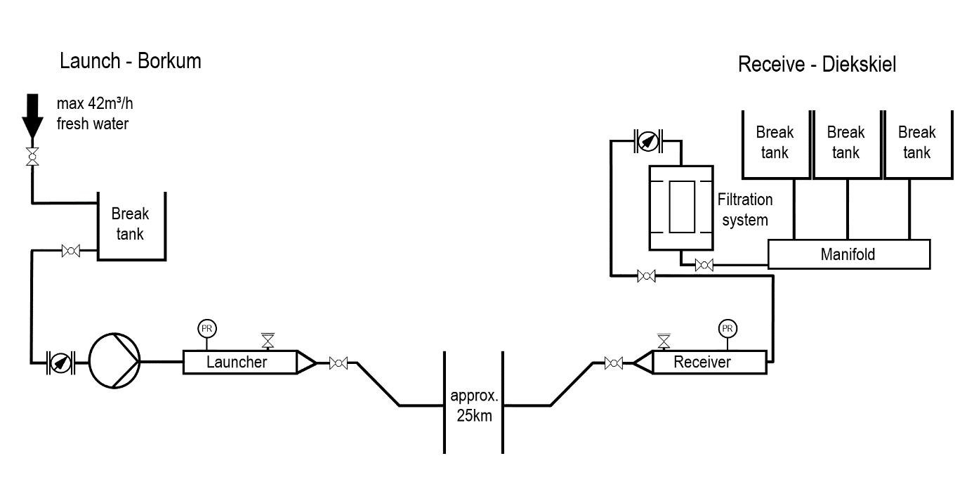
Among others, the East Frisian island of Borkum is supplied with gas by EWE Netz GmbH. This project was very sensitive since major parts of the pipeline route, as well as the launch location, are located in a national park and UNESCO World Heritage Site. Planning and preparation included liaison with relevant local and environmental authorities from the start to ensure that the project would have the minimum possible footprint. Scheduling the field works was governed by both breeding periods of protected bird populations and requirements of downstream consumers. Specialised filtration equipment to clean the water used to propel the inline tools was included. 3P Services’ work included provision of pumping spread to propel the inline tools. Inspection technologies to be deployed included GEO (geometric), MFL, UT and XYZ mapping in the 5 in. diameter line.
Field works were scheduled during mid to late summer after preparation of the ‘low impact’ launch and receive positions were complete. All onsite personnel received specialised training from a third-party nature conservation consultant. The island of Borkum is separated from the mainland by tidal mudflats and subsea, which serve as reference positions for the XYZ unit when deployed along the pipeline during low tide.
The line was flooded, cleaned by use of a chemical batch, cleaning tools and inspected by means of GEO/XYZ and ultrasonic inline inspection tools. In a last step, the line was dewatered and dried with nitrogen. All propellant used during this operation was run through the filtration skid, and then tested before either being drained or disposed of separately.
The inspection operations were completed within a tight schedule, and the final report delivered on time. Using this information and in conjunction with the regulator, the client is performing an extensive campaign of investigating features that were reported.
Introduction EWE Netz GmbH awarded 3P Services the inspection of a 5 in. gas pipeline connecting Borkum with the German onshore grid. The natural gas transported through the pipeline is fed into the local grid on the island and is used mainly for domestic heating.
The pipeline in question was built in 1981 and had never before been inspected by use of inline tools. No pipeline launcher or receiver installations exist. For operational reasons, the gas flow could not be regulated to accommodate velocities suitable for inline inspections, and the decision was
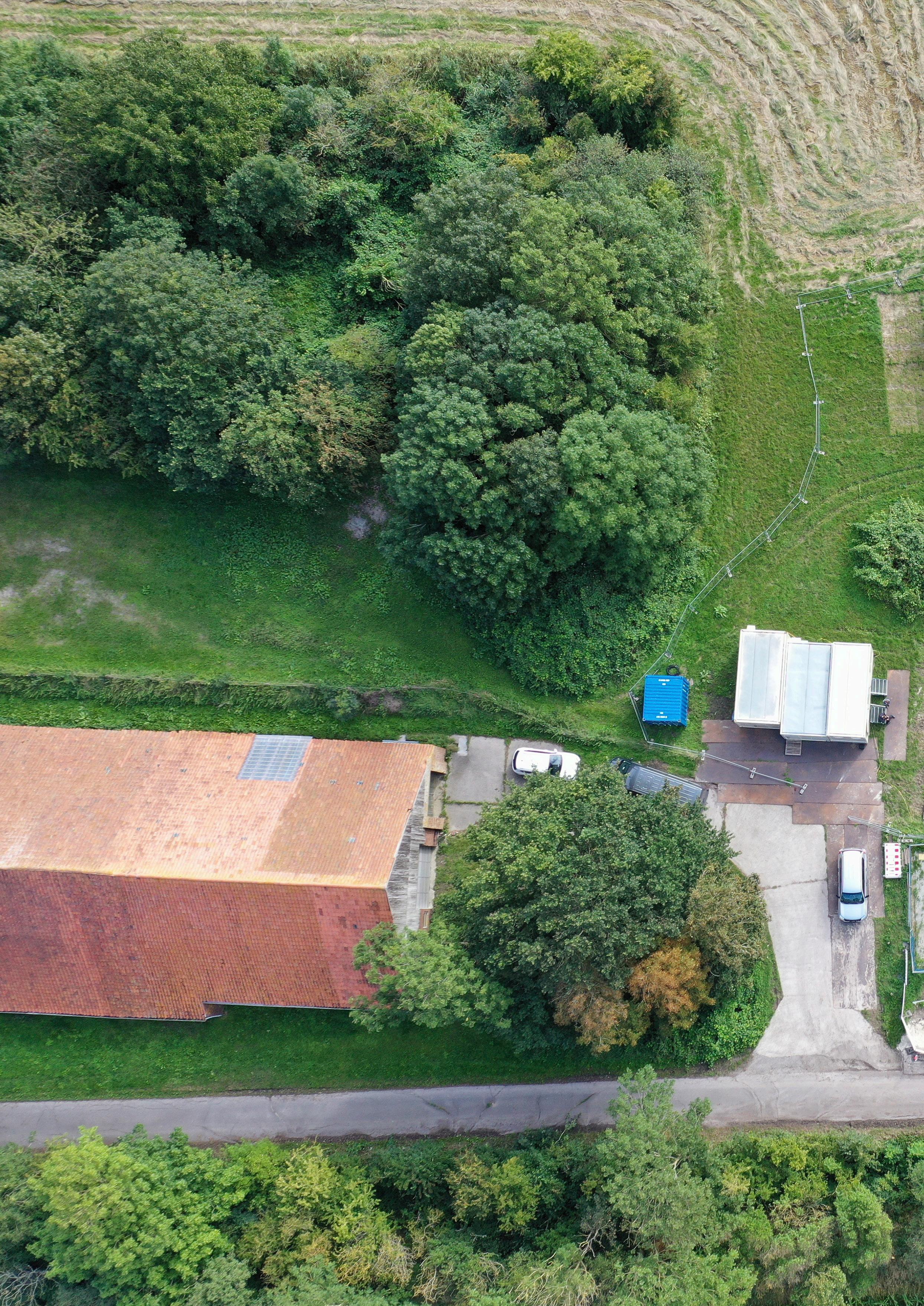
Figure 1. Onshore receiving site with filtration system and break tanks.
therefore made to conduct all operations in fresh water with a temporary pumping spread.
Given the sensitive environment and the nature of the Wadden Sea, a full set of inspection tools was prepared including cleaning tools, a geometric calliper inspection tool (GEO), ultrasonic wall thickness (UT) and magnetic flux leakage inspection (MFL/DMR) tools in conjunction with pipeline mapping (XYZ). The progressive pre-ILI tool sequence considered various potential types of geometric deformation caused by dropped anchors, misalignment due to tidal currents, as well as general corrosion caused by coating damage.
Project preparation All relevant authorities and governmental bodies were informed of the intended inline inspection operation at a very early stage. Throughout all phases of the project, communication between the relevant parties were open, constructive and allowed for a seamless project execution.
The inspection schedule was influenced by a number of factors, one of which was the requirement to affect the inhabitants of the island as little as possible. The inspection was therefore only possible during the warm summer months. Operational timing was also impacted by breeding periods of the resident bird population, and the rest periods for migratory birds. Since the island of Borkum is also a popular destination for tourists, the inspection was scheduled between Easter and summer holidays, as all equipment and machinery had to be brought onto the island on ferries that were fully booked during the holiday seasons.
For the purpose of water management and environmental regulations, it was decided that all inline inspection tools were to be launched on the island of Borkum and received on land.
As the water pumped through the pipeline could not be discharged in either a national park or nature conservation area, specialised water handling was required. All pumped water was run through a filtration system, stored in break tanks and tested for contamination by laboratory analysis. Only if green-lighted by the results of the laboratory tests, the water could be disposed into a ditch. Since laboratory analysis was scheduled to take place at least once day, and would have to be conducted after every run, even if the water pumped in the proceeding run was deemed okay, break tank capacity equal to more than the line fill was required at the eventual receiving site. Regulations in the national park demand the footprint at this location be as small as possible, and break tanks and filtration system are positioned in the nature reserve onshore. All temporary equipment was placed on mats to distribute the weight and limit the amount of compaction of the soil. A maximum of 40 m3/hr of fresh water as propellant was supplied by local public utilities via a hydrant close to the launch site. Prior to mobilisation, factory acceptance tests of all inline inspection tools were conducted. EWE Netz provided a test spool with artificial defects, hidden underneath a layer of external wrapping. The artificial defects ranged from general corrosion to pitting defects. All defects were scanned in 3D before the spool was wrapped, and the spool was then incorporated into the pump test layout at 3P Services’ testing grounds. Both the MFL and the UT tools were pumped through the spool and the recorded data sets were analysed and presented to EWE Netz GmbH. Position referencing markers were placed along the pipeline route every
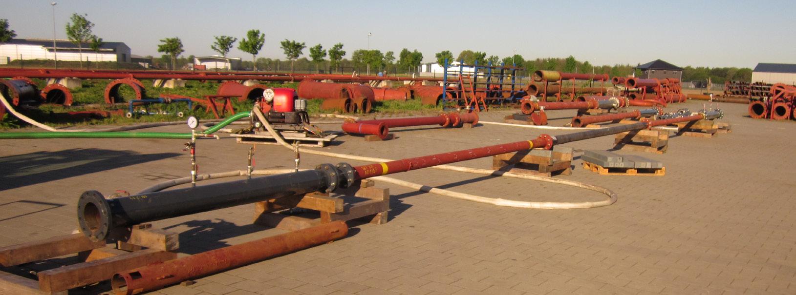
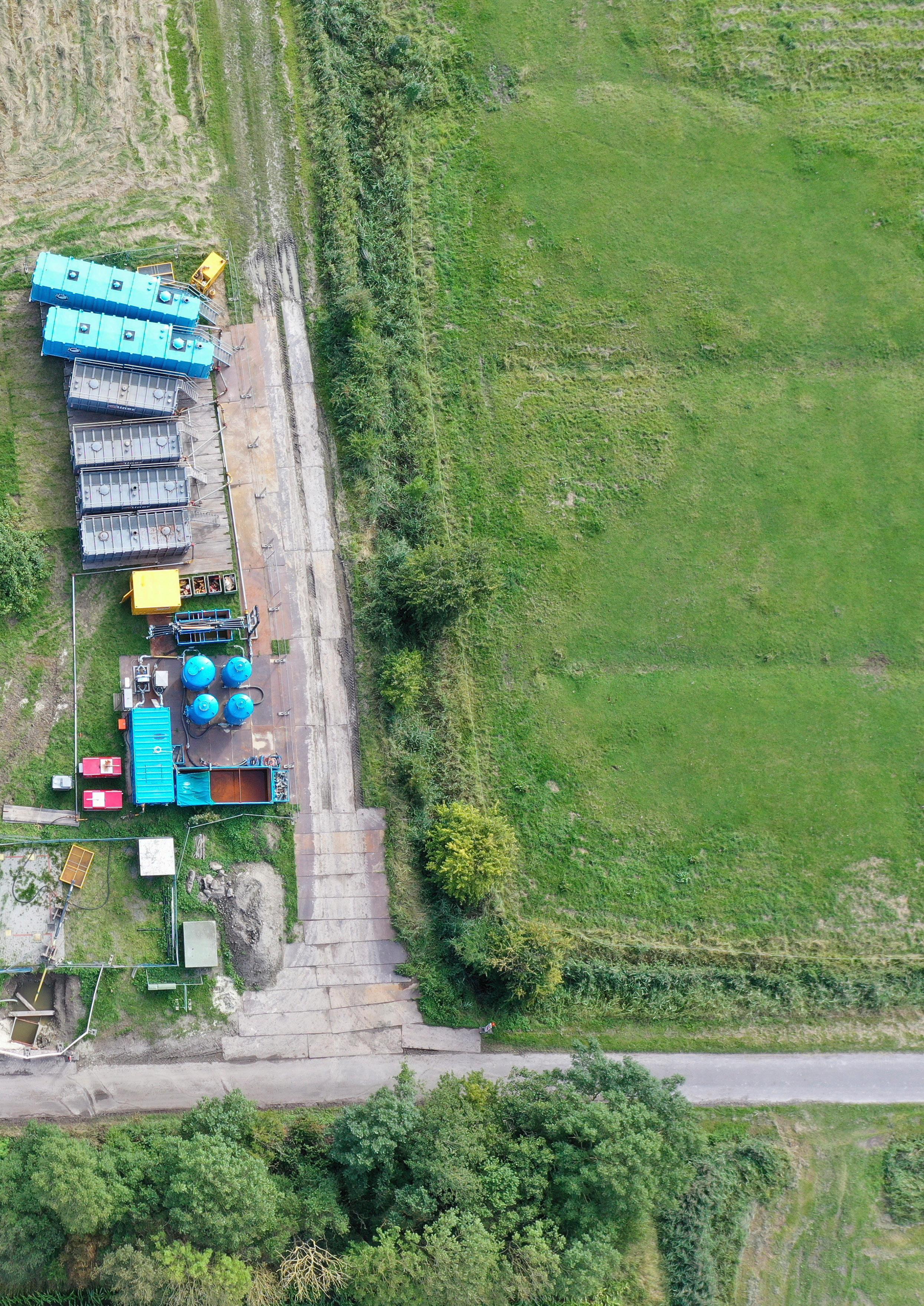
Figure 2. Equipment spread on launch and receive site.
Figure 3. Factory acceptance test of ILI tools incorporating blind test spool.