IT IS MY ENDURING PLEDGE
to always deliver on my commitments, never underestimating the critical role that pipelines play as energy lifelines in fueling everyday life and unforgettable experiences.
It is who I am. I am a pipeliner.
We are pipeliners too.
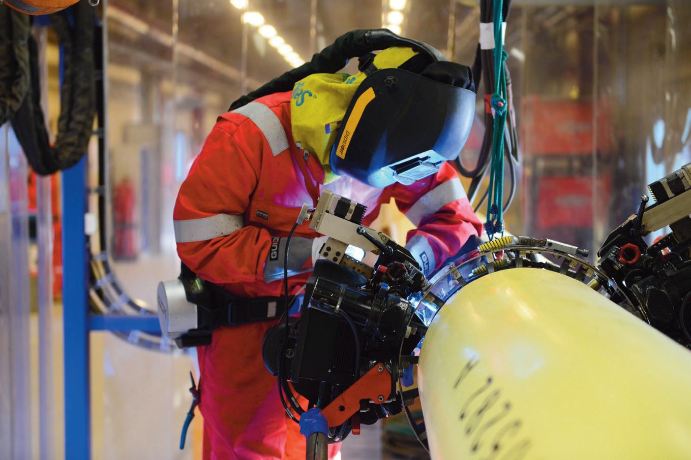
Keeping product in the pipe is a big job that’s critical to protecting the environment, requiring specific expertise and technology to ensure success.
TDW brings industry-leading application engineering teams, innovative solutions and world-class technicians to help you deliver on your goals. We remain committed to supporting you and the industry in moving toward a more sustainable energy future.
The world counts on you. You can count on us.
For the life of your pipeline.
©2022 T.D. Williamson
tdwilliamson.com
Rome wasn’t built in a day, and neither will your cybersecurity defences be, says Michael Bradley, Director of Utility Services, Everline, USA.

8
f you’re an interstate transmission operator, especially a TSA ‘top 100’, this isn’t the article for you; this one is for the utility operators. In the world of pipeline security, I am starting to see that there is a significant understanding gradient ranging from those ‘critical’
transmission operators who have been continuously engaged by the TSA for years, to utility operators who are just learning what cybersecurity has to do with pipelines. Over the last couple of years, I have been in numerous meetings in the utility space where

directives and guidelines have been discussed, and confusion abounds.
Part of the confusion, I feel, can be attributed to the very nature of security rules and regulations; they aren’t promulgated in the same way that pipeline safety regulations are. Another issue is that they just
9
don’t read like the federal and state regulations that most pipeliners can recite by heart. Lastly, natural gas distribution has, until recently, not been a strong focus of America’s security apparatus, and thus gas utilities are, for the most part, getting in the game late (when compared to the decade-plus that electric operators have had with NERC CIP).
Since 2005, the electric side of the energy delivery industry has been working within the guidelines of the Critical Infrastructure Protection standard published by the National Electrical Reliability Council. If you aren’t already familiar with it, you may have at least heard of it by its acronym: NERC CIP. NERC’s standards include prescriptive guidance on security topics such as personnel training, information protection, supply chain risk, and incident reporting, all of which are key to keeping the Bulk Electrical System safe from would-be bad actors. Fast forward to 2022, 17 years later, and the gas side of the business is now getting its CIP treatment, beginning with TSA directives, which will inform rulemaking moving forward.
New directives
In the wake of the Colonial Pipeline incident that resulted in significant disruptions to the East Coast’s access to vehicle fuels, the TSA dusted off its 2018 ‘Pipeline Security Guidelines’ and gave them a brief update. In parallel, they issued Security Directives to the top 100 ‘critical’ pipeline operators in the US. ‘Security Directive Pipeline-2021-01’ (SD1), issued 28 May 2021, essentially required operators designated by the TSA as ‘critical’ to do the following: report cybersecurity issues to the Department of Homeland Security, assign a point-person to be reachable by the TSA and CISA 24/7, and perform a gap assessment against the guidelines.
SD1 was followed by ‘Security Directive Pipeline-2021-02: Pipeline Cybersecurity Mitigation Actions, Contingency Planning, and Testing’ (SD2) in July 2021. This directive was of limited circulation under the protections of 49 CFR 1520, the Sensitive Security Information (SSI) standard. However, the general requirements were as follows: implement a list of mitigations prescribed by the TSA, develop a cybersecurity response plan, and test the effectiveness of cybersecurity practices annually. SD2 was eventually superseded by ‘SD2C’ in July this year, which incorporated feedback from industry and Congress. Essentially, the Directive was revised to provide additional flexibility in achieving the expectations set out in SD2.
As you read those last two paragraphs, you may be inclined to think this was straightforward. But, consider that there are thousands of pipeline operators in the US, and only a fraction of them received letters with these prescriptive instructions. SD2 was classified as SSI and thus not publicly released. But of course, the entire industry heard that there was a second directive, and many wanted to get ahead of what they felt would come to them anyway. Some non-critical operators even commissioned gap analyses against the SD2 criteria, even though they
could not know the criteria. Within larger organisations, I would often come across stakeholders that were generally aware of the directives, perhaps even some of what they required, but were still unclear as to whether the company they worked for was considered critical, what specifically was required, and what role their organisation needed to play. Thankfully, trade associations jumped in to host calls and workshops, align on practical interpretations of vague language and seek clarification from the TSA on various points. It is worth noting here that while the guidelines weren’t new in 2021, they, like most of the written standards and practices on pipeline security, were focused on interstate transmission. Much of the language and requirements were found to be challenging to utilities on the first read.
A global perspective
At this point, I think it may be prudent to explain that my background is in pipeline operations, not security. I spent the first decade of my career with large, investorowned utilities, working in roles spanning field operations to compliance and ethics. The federal and state pipeline safety regulations have been drilled into me since my first day as an associate engineer, and I think that’s why I struggled so much the first time I laid eyes on the TSA’s guidelines. While they came from a US government agency, and they refer to pipelines, they certainly didn’t read like any regulations I had interacted meaningfully with to date. I was embarrassed to admit this until I realised I wasn’t alone. Whether it was the confusion around ‘guidelines’ being mandated (as opposed to being guidance), the lack of definitions provided for key terms, the strange omissions/inclusions in the critical asset methodology, or all the above.
But really, the language wasn’t the toughest part; implementation was. Of course, you might say, it’s always easier to plan than it is to implement, and sure, but perhaps not for the most obvious of reasons.
The challenges with executing what the TSA was expecting also presented a unique challenge – the centre of the Venn diagram depicting those who speak pipeline and those who speak operational cybersecurity is very small. And that shouldn’t have surprised me; in my time in the industry, I hardly ever heard of a significant correlation between pipeline operations and security apart from vandalism. Every so often, either at a company I worked for, or elsewhere in the industry, we would see examples of physical vandalism as a form of protest or amusement, and occasionally performed with malice. Terrorism, while not unimaginable, was not top of mind to the average pipeliner. But it needs to be.
We need to look no further than the news to see that the global energy supply chain is the focus of both the average consumer and nation-states alike. Major international pipelines are being used as economic weapons in the European conflict, and the global stability of energy supply and pricing is delicate. What better time to create further chaos or damage to an adversary than
10 World Pipelines / OCTOBER 2022


STATS GROUP Managing Pressure, Minimising Risk Remote Tecno Plug® Non-intrusive Inline Isolation The Remote Tecno Plug® provides fail-safe double block and monitored isolation of pressurised pipelines while the system remains live and at operating pressure. ZERO-ENERGY ZONE PIPELINE PRESSURE DUAL Leak-Tight Seals double block & monitor isolation isolated pipeline taper lock grips TYPE APPROVED 10” - 56”
when its population already feels the pressure of rising prices and unsteady availability.
OT systems
The challenge is that while electric infrastructure operators have had nearly two decades of practice with NERC CIP, pipeliners are playing catch-up when considering the threats to the world’s energy infrastructure today. Security is not just a concern for the major transcontinental pipelines and metropolitan utilities; bad actors will gladly exploit any vulnerability they can find. Some of the juiciest targets are the OT systems operators, big and small, used to monitor and control the physical assets. OT systems include a myriad of hardware, software and communications networks, and require specific expertise to be secured. Herein lies two challenges for pipeline operators (amongst others) that I would categorise ‘domain’ and ‘resources’.
Domain
Let’s start with domain. To successfully design and implement a mitigative risk strategy to meet TSA’s expectations, the responsible party needs both the technical expertise and the ownership of the asset(s) or department(s) which must implement the mitigations. The expertise needs to be in one’s knowledge domain, and the assets that need protection must be in their responsibility domain. Likely, your company doesn’t yet have a Director of OT Security or similar, so there may not be a perfect ‘owner’ for operational cybersecurity preparedness.
Large pipeline operators will likely need the collaboration of departments such as corporate security, human resources, pipeline operations, control rooms, integrity management, and of course, IT, to address the breadth of the TSA guidance. Each of these departments will have its own plans, policies, procedures, and budgets, much of which may need to be adjusted to accommodate the cross-cutting cybersecurity mitigations. No single entity satisfies either the expertise or responsibility domain question.
For smaller operators, the opposite problem appears; the likely owner would be the owner of every other pipeline programme, the Manager/Superintendent/ Director of Gas Operations, who likely does everything from writing procedures to updating the NPMS. Accountability domain is almost guaranteed in these situations, but a lack of domain expertise (OT security specifically) is likely a hindrance.
Resources
On to resources. While the largest operators are typically better resourced than the smallest operators, they also typically have the largest installed asset bases and more complex operations, policies, and processes. Frankly, there’s both more to secure, and it’s often more difficult to secure than for smaller operators. Security, like most cross-cutting risks, affects the business in a myriad of ways, from how we conduct employee background checks, to how we secure
mobile devices, to how we configure PLCs. The more complex an operator, the more analysis, planning, and investment is likely required. At the smaller end of the spectrum, assessing an operator’s attack surface is likely a simpler task, however, the mitigations may carry an outsized price tag. The replacement of hardware, communications devices, or the procurement of services could present a significant cost. Because the ‘guidelines’ are not currently mandated for most operators, it may be difficult to convince ratepayers, interveners, or boards to bear the costs.
Explaining cybersecurity
I believe that to lay out and execute a successful cybersecurity defence strategy, you should first solve the domain issue. Ensure that your team(s) focusing on this topic possesses adequate security expertise, knows the pipeline operations as it is done specifically at your company, and are granted the authority (not just influence) to implement mitigations where needed.
Resource constraints will always be present, for operators of all sizes, from investor-owned, to private, co-ops, and municipalities. The key here is that Rome wasn’t built in a day, and neither will your cybersecurity defences be; however, they should be built in a riskprioritised manner. Not all mitigations need to be expensive, either; often, there are security hygiene and process improvement opportunities that cost very little (Hint: ditch the thumb drives and airport Wi-Fi).
Once the internal team is in place and equipped for success, a third-party gap analysis against regulatory guidelines, such as the National Institute of Standards and Technology’s (NIST) ‘Cybersecurity Framework’ (CSF), NIST SP 800-82: ‘Guide to Industrial Control Systems (ICS) Security’, and industry-standard IEC 62443 will populate the areas in need of attention. Documentation is key; not all gaps need to be fixed simultaneously, but it is likely better to demonstrate due diligence in finding and road-mapping the gaps than to have nothing to show an auditor, regulator, or investigator should you need to.
The inclusion of cybersecurity threats on your risk registers and in your 49 CFR-driven emergency management plans and transmission integrity management plans are a must; PHMS has partnered with DHS/CISA to include specific questions in their integrated audit protocol related to these programmes. The next time you see PHMSA or your state programme for a programmatic audit, they will also ask you how you intend to operate your pipeline ‘manually’ should your IT or OT systems be compromised.
Conclusion
Put simply, the threat of hacktivists, or terrorists, prodding our infrastructure, looking to cause damage, is significant. It spares no operator, and most are at least somewhat unprepared to tackle it alone. The best approaches, regardless of scale, require installing the right programme leadership, engaging expertise in both security and pipeline operations, and equipping the team with the authority and resources needed to implement.
12 World Pipelines / OCTOBER 2022
ne of the most important aspects of control room management in pipeline operations is effective alarm management. Every control room should focus on proactively preventing escalation to abnormal operating conditions (AOCs) or emergency situations.

To achieve this goal, operators should look for ways to optimise human performance in alarm management. This includes building a system where control room operators can achieve situational awareness during all operating
conditions. This way, your control room can operate safely and effectively.
What goes into an alarm management system?
Pipeline operators need to strike the balance of accomplishing business objectives while doing no harm to people, property, or the environment. By implementing a system that equips human operators to respond to alarms, your operation can improve alarm response to any threats.
Ross Adams, General Manager, EnerSys Corporation, USA, talks optimising the human element of alarm management to support control room performance.
13
Ideally, an alarm management system should be designed to ensure that all alarms are received at the pipeline operator’s console in the appropriate time frame, and with the most relevant information. This way, the operator is equipped to act before an unplanned situation or shutdown occurs.
The ideal flow is that an alarm comes into the system, a pipeline operator performs activity to address the alarm, support personnel are mobilised, and a situation is prevented before an operator’s system needs to be shut down.
The goal of alarm management is not to never trip safety shutdowns. Rather, the idea is to prevent escalation to a shutdown by effectively responding to alarms. Alarm management focuses on how to equip the operator with notifications, graphics, and action plans to see and understand the abnormal operating condition, and provide them with the proper action steps to avoid tripping safety shutdowns.
1. Rationalisation
The starting point to effectively operate without shutdown is ‘rationalisation’. This includes defining the severity of each alarm, the time available to respond, the possible root causes of the alarm, the methods of diagnosis, and the recommended actions. In many existing alarm management systems, it is common to find that most alarms aren’t designed to achieve this operating goal.
Often, the most challenging constraint is that there is very limited time available for human response. For example, when the alarm setpoint is at or near the safety trip, the operator typically has very little time to respond and avoid a shutdown. Providing adequate response time often requires redesigning the facility, the automation, and/or the process. This can place significant strain on operations. However, operators must find ways to improve the performance of their system so that human operators and support personnel have ample time to identify, analyse, and respond to each alarm. What’s the solution?
2. Analysis
Pipeline operators should engage in a regular and intensive alarm analysis process in order to identify bad actors and prevent alarm floods that inhibit the pipeline operator’s ability to process the alarms they are seeing.
A key aspect of this analysis is defining effective alarms that will provide operators with adequate time to recognise and respond to the threat so that you can maintain safe operations without shutting down. It’s important to place operators in a position of strength instead of constantly reacting to alarms.
Operators need to translate the desire to accomplish their business objectives into operational instructions for the operator to be able to identify alarms and manage situations before they escalate.
3. The plan-do-check-act cycle
Operational instruction is critical to provide control room operators and support personnel with the necessary information and guidance so that they can perform the
plan-do-check-act cycle (PDCA). Following the PDCA cycle will ensure that personnel can achieve situational awareness in all operating conditions.
• Plan: Do your personnel understand the alarm management plans, processes, and procedures that you have implemented?
• Do: Are personnel following the proper sequence of steps in alarm response to formulate the proper response to each alarm?
• Check: Are you checking to see whether personnel followed the steps when responding to each alarm so that you can drive continuous improvement?
• Act: Are you acting on the check by holding personnel accountable for following the steps to help reduce the risk of safety incidents?
Implementing the full PDCA cycle in the control room carries additional benefits of strengthening your safety culture. It will positively influence how operators act, behave, and think during each operating condition.
The importance of culture to support alarm management
If the purpose of alarm management is to enable you to operate without shutdown, then each alarm presented to a pipeline operator must be meaningful. If not, there is a risk that the operator will ignore or de-prioritise certain alarms.
Over time, a pipeline operator may become conditioned to mentally separate or filter alarms in their mind. Instead of treating each alarm as a threat that needs to be addressed, they might ignore alarms that do not appear to be a threat. But, what about when there is a threat that needs to be contained?
This culture of complacency was a contributing factor to the high-profile Enbridge Pipeline Oil Spill in Marshall, Michigan, USA, in July 2010. According to the official incident report, the control room operators did not take the threat seriously because they ‘misinterpreted’ the rupture and ignored warning signs.
This scenario captures the importance of control room culture. Pipeline operators must reinforce the value of treating each alarm with healthy concern when an alarm is displayed in their console. It’s not up to the operator to pre-determine whether an alarm is actually critical or not. Operators need to remain vigilant when analysing the alarm to formulate the right response.
There are many ways to support a healthy safety culture. Consider actions that should be included in your refinement of the alarm management system:
) Rationalise and re-rationalise the alarms.
) Perform monthly AOC response reviews.
) Utilise monthly AOC findings in lessons learned training.
) Maintain communication involving controllers in setpoint and descriptor reviews.
14 World Pipelines / OCTOBER 2022

) Validate proper change management by including the control room in key conversations.
) Ensure that point-to-point, rationalisation, setpoint review, and training occur before the asset comes under control.
Improving and refining the system will give human operators confidence in the quality of the alarms presented to them in their consoles. Furthermore, this process will enable operators to execute the PDCA cycle during all operating conditions.
A key component of the PDCA cycle is building strong feedback loops to gather input from personnel to understand how best to present information to them. The alarm management system needs to be optimised for the human element so that each individual can effectively use the SCADA system to perform duties. Consider gathering the following input from operators:
) What is working in the alarm management system?
) What is confusing (e.g. bad actors generating false alarms)?
) Are the alarm activation steps clearly defined for you?
) What is unclear when responding to each alarm (e.g. alarm floods)?
) Do you understand the alarm priority sequence?
Then, pipeline operators should continue to refine their presentation of alarms to personnel to continue strengthening human performance. This captures the importance of optimising pipeline SCADA and HMI systems to support the operator.
The role of pipeline SCADA and HMI
Effective alarm management depends on robust SCADA systems so that pipeline operators can quickly gain clarity about what they see on their HMI displays and achieve situational awareness.
Operators in the control room need to be able to identify abnormal situations and follow the appropriate intervention steps. This can be achieved when the SCADA system is set up so that crucial information is presented to the operator when needed, and in the form they need.
1. Software tools
Once the SCADA system is set up properly, your operation needs access to the right tools to streamline your operation’s alarm response. Specifically, you should utilise alarm management software tools that are designed for pipeline operations and enhance the effectiveness of your SCADA.
2. Services
Additionally, it’s important to work with subject matter experts who can provide you with guidance on how
to blend technology and the human elements of alarm management to optimise performance.
The combination of software tools and services creates the right solutions that fit the unique characteristics of your pipeline operation.
At EnerSys Corporation, we provide a software module, ALMgr, within our POEMS® Control Room Software Suite (CRM Suite) that is specifically designed for alarm management. The features and functionality included in ALMgr enable operators to manage the alarm rationalisation process and assist with real-time response to alarms.
We back our software tool with expertise from a team of consultants that can analyse your control room, SCADA systems, HMI displays, and human activity to identify ways to improve performance effectiveness.
Through our combination of software and support, your operation will be able to:
) Generate alarm response sheets (ARS) to guide operator response.
) Streamline your operation’s alarm response.
) Reduce alarm frequency and floods.
) Enable situational awareness to help human operators perform their duties effectively.
) Improve response time to plan, do, check, and act.
) Cut the cost of the rationalisation process.
) Determine whether fatigue is a factor in alarm response (i.e. fatigue management).
) Analyse the results of each alarm event to improve operational efficiency.
) Enable communication with supervisors about bad actors in the system.
) Generate records that track results that can be used to improve future performance.
Many companies can provide your operation with software tools for alarm management. Others can provide you with consulting. But, it’s rare to find a provider of both software and services/support. Through our natural compliance solutions, we foster strong relationships with pipeline operators to drive toward continuous improvement in the control room.
Consider ways that your operation can take the appropriate steps to build an effective alarm management system. Then, look for ways to strengthen your safety culture. Finally, consider utilising our solutions to ensure that personnel in the control room can perform critical duties in a safe and effective manner.
16 World Pipelines / OCTOBER 2022
alls for new and improved critical infrastructures globally are being tied more and more often to the modernisation of energy transportation for a cleaner, more sustainable future.
To meet demands while figuring out the short and longer-term planning and problem-solving aspects, in consideration of this cleaner energy transition, there is much discussion to be had in regards to the potential performance, capacity and throughput of liquids and gas pipelines.
The analysts envision a novel blend of repurposed oil and gas pipelines and networks, as well as the development of new pipeline systems, compressor stations and storage reservoirs. These efforts will support expanding industry requirements to sequester carbon while effectively transporting, storing and moving hydrogen-enriched natural gas.
Expected to take several decades, the move away from carbon intensity and toward net-zero emissions won’t be swift. By and large, it will be dependent on the build-out and optimisation of such energy related pipelines, storage hubs and infrastructures. A considerable amount of cooperation will be required as governments, policymakers and forward-thinking organisations consider the legal and regulatory frameworks that have already been or will need to be constructed, to launch a contemporary and more interconnected era of energy production, transmission, and distribution.
Added to this list of complexities are tests related to outcroppings of geopolitical issues and socioeconomic concerns associated with rising demands around different parts of the globe for greater energy independence, energy security, and more access to renewable forms of energy.
There has been a global increase in demand for products being transported by pipeline, including natural gas, carbon dioxide (CO2) and hydrogen. Part of this is being fuelled internationally by carbon capture, utilisation, and storage (CCUS) projects, hydrogen blending, and similar decarbonisation-related activities in Europe, the US, and other parts of the globe.
For pipeline operators, the cleaner energy transition must come to pass concurrently with keeping everyone safe, protecting one’s corporate reputation, and seizing on opportunities to stay on top of design, engineering, and operational scenarios, in addition to increasing pipeline profitability by optimising movement cost.
It would be difficult to overstate the role reliable, built-for-purpose technologies will play to help companies overcome roadblocks found on the pathway to decarbonisation.

Paul Dickerson and Dr. Jennifer Worthen, Emerson, USA, discuss building pipeline capacity to plan for a cleaner, optimised energy future.
17
The overarching question for many draws back to, “How can we meet future demands for more energy, with lower costs and fewer emissions, while taking a more sustainable approach that is responsible, reliable, and adds value across the entire pipeline supply chain?”
The chain
From an operations standpoint, one quandary is to better manage and optimise pipelines amid increasingly diverse sets of product flows – by ensuring the capacity is available to plan and perform –and deliver.
Pipeline networks go far beyond point A to point B; there are numerous supply points, delivery points and interconnections. Pipeline operators also routinely deal with fluctuations in demand that require near-constant re-evaluation of consumption rates that change on a daily, hourly, or minute-by-minute basis.
Pipeline assets are managed as part of an overall supply chain – with products making their way to buyers from the production site to pipelines, and finally to distribution points. To optimise the movement of products and improve both profitability and flexibility of the pipeline, operations must be planned in the most efficient way possible. They must not only satisfy the demands of shippers, but also maximise internal efficacies.
View this from the perspective of a food trucking company hired to deliver assorted produce, including the logistical responsibility of caring for many different types of fruits and vegetables while they are being transported both from and to their respective pick-up locations and drop-off points.
From this point of view, getting the correct products to the right market while still ripe and on-time requires certain sets of preplanned actions, perhaps starting days in advance. There is logistical aptitude involved as products are both categorised independently and taken into account as a whole.
At a certain point, these types of premeditated actions may become so common that it feels as if they could be automated –the various tasks that must be performed to allow for the trucking, shipping, and delivery of goods to continue.
In this same vein, pipeline operators and energy companies are seeking to leverage immense amounts of raw data via investments
in tech-enabled software – helping automate the evaluation of delivery capacities within networks. This trend will help ensure operational successes as end users become more dependent on robust and timely access to sufficient supplies of energy resources, such as hydrogen and natural gas.
Effective overall
In the long-term, what can be done to plan for and optimise both the design of pipelines, as well as pipeline operations and product flows, as more carbon sequestration and pure or enriched-hydrogen projects shine through?
How do I make the most efficient use of a new energy pipeline or expand an existing network to move product? What is the appropriate diameter of pipe and the potential need for additional pressure on my systems? Can I keep construction costs low while meeting capacity requirements? How do I determine the amount of energy needed to drive gas from a line or electricity to drive compressors?
In short-term planning, supply chain issues must be met head-on, day-to-day, while remaining vigilant by preparing for peak season demands, as well as contingencies such as cold snaps, prolonged freezing temperatures, major weather swings, or excessive heat waves. Drains on the power grid caused by an unforeseen circumstance or a peak-season weather event have been known for knocking out power, sometimes for days or weeks.
Such extremes are being reported on more often and on a more granular level with greater attention being called to events, such as requests to limit power, rolling planned outages, and prolonged power outages that can impact residential, commercial, and non-profit communities.
What could go wrong? What could go right?
Emerson has been enabling oil and gas companies to mitigate and overcome related challenges. Its PipelineStudio software has a singular focus – provide solutions to planning, engineering, and design problems. It was developed to support the ongoing decisionmaking processes of pipeline owners and operators by giving them the confidence to act.
It has been used as an application to achieve favourable business outcomes, firstly from an engineering applications point-ofview and secondly from an operational applications perspective. As a design, planning and analysis tool, the software combines graphical configuration and reporting devices with simulation engines.
Pipeline operators are tasked daily with maintaining optimal operating conditions to satisfy demand while considering all pipeline constraints. From an economic comparative standpoint, software such as PipelineStudio, as one example, can help determine the appropriate equipment – and associated costs – for looping a pipeline or adding pump or compressor units to improve throughput.
The software was engineered to provide design analysis of networks, line size and capacity studies, as well as deliverability analysis, which may be used to determine whether a given network can meet increasing future demand, either with or without additional equipment.
 Figure 1. Companies able to leverage raw data via simulation software such as Emerson’s advanced pipeline applications will benefit from greater network capacity to transport both existing and newer energy products.
18 World Pipelines / OCTOBER 2022
Using innovative, ever-evolving solutions and our expert knowledge, we provide the best services to support all of your operations.
We have the in-house capabilities to combine the services you need: inspection services, pipeline management, environmental services, and industrial services.
Contact our team for more details: info@intero-integrity.com

intero-integrity.com
An example of this is the determination of maximum throughput, which requires calculation of the largest possible flow increase without violating a minimum delivery pressure. Users can compare and evaluate different operating scenarios such as variable flow and delivery pressures over specified time periods.
Rapid configuration and simulation of various supply/demand scenarios makes way for determining the most economical pump strategy. When the associated performance curves and detailed operating specifications are provided, the software allows for detailed calculations and a report for each unit, including the power used during the operation.
At times, cyclical flow conditions in some pipelines cause certain pump or compressor stations to operate below peak efficiency. Shutting these stations down and shifting the load to others enables the user to maximise the available horsepower and thus conserve energy or power.
Using a fixed configuration of the network, PipelineStudio is supplied with flow and pressure boundary conditions from a pipeline system. Nominations, provided by a gas load forecaster, are used to create a transient scenario. Steady-state and transient simulations run automatically at the start of the gas day. Essentially, it is a decision-support application designed to complete a fasterthan-real-time simulation of the pipeline for the next gas day – with results presented to the operator. This helps identify any problems associated with the nominations and provides information ensuring that the pipeline is operated safely, all while satisfying contractual obligations.
Pipeline systems operating during peak season can be analysed to determine whether the system can meet increasing future demands, or whether additional equipment is necessary. Maintenance of key pressures in the network, line pack analysis, and manipulation of supply or delivery setpoints can each be performed.
2050 blend
The Heartland Institute reported that in the US alone, total liquids pipeline safety incidents have decreased by 17% over the last five years, including a 31% drop in incidents impacting the environment or people. That’s good news for pipelines and operators as they are still considered among the safest, most economical methods of transporting oil and natural gas.
CCUS is attractive because it can reduce emissions from existing oil and gas production capacity quickly through retrofits, and can enable large-scale dispatchable hydrogen production. By 2030, the total length of hydrogen pipelines globally will need to quadruple to >20 000 km, according to the International Energy Agency (IEA) and their Net Zero Emissions (NZE) by 2050 initiative.
Interest in projects that combine CCUS with conventional technologies is on the rise, yet the ability to reach hydrogen-strategy targets will rely on faster development of hydrogen transmission systems. The IEA data suggest fast action is needed in the next 10 years to meet projected net-zero targets, and recent analysis of the current project pipeline had proposed that only ~18% of this demand would be met.
Total hydrogen demand from industry, the IEA stated, is expected to expand 44% by 2030. This will occur alongside the increasing importance of low-carbon hydrogen – amounting to 21 Mt in 2030.
Large-scale hydrogen deployment will need to be buttressed by an effective and cost-efficient system for both storage and transport. The goal is centred on the strategic design and positioning of such critical infrastructures to connect supply sources to centres of demand, in turn establishing a highly liquid market. The scale-up to meet global demand, reduce costs and make improvements in efficiency, lifetime or process integration will also include technologies such as electrolysers, fuel cells and CCUS-equipped hydrogen production.
Optimisation equations
The optimisation of both renewable and non-renewable sources of energy are key factors for many pipeline operators, including those closely monitoring the correlation between investments in technologies and desired business outcomes. The industry has embraced optimisation, including various optimisation tasks that exist from design to operation in all stages of the pipeline sector. The focal point is on the ability to reduce pipeline costs.
Frictional resistance is the main reason for energy loss, and how to reduce it while retaining delivery capacity is one of the primary concerns. Polymetric drag reduction application techniques are essential for energy optimisation and emission reductions initiatives in the transmission and distribution market. Known as drag-reducing agents (DRA), these long-chain hydrocarbon polymers have properties that reduce friction and allow increased throughput and flow volume. The chemical additive is in high demand as it allows for the pumping of greater quantities of product through pipelines.
DRA optimisation considers pump schedules, flow rates during specified times, and suggested DRA injection rates designed to meet user-defined target throughputs. Multiple variables including different boundary conditions, product properties and devices in the configuration will have an impact on the probable solution.
There is a price associated with the energy consumption to transport a barrel of oil, as well as the cost of DRA utilised. Cost vs production movement is of special interest to pipeline operators who find value in figuring out the sweet spot for options to
 Figure 2. Emerson’s PipelineStudio allows companies to accurately predict future capacity based on simulations generated from available data to proactively manage nominations, maintenance, etc.
20 World Pipelines / OCTOBER 2022


minimise the total cost to move each barrel of oil from origin to destination.
Pipe size, the scale of pipeline lengths, velocity, viscosity, the spacing of pumps and compressor stations, the cost of electricity, the cost of DRA, minor frictional losses, and other variables may all influence optimisation outcomes, and may be included in the final analysis.
DRA, however, does not work alone. Pumps in the pipeline, for example, are still needed at various stages to increase compression. Timing is also super critical to both peak and off-season pricing, as well as when figuring out a more cost-effective way to run at a higher flow rate overnight, or to meet spikes in demand because of unforeseen events. The scope of demand can change on a dime.
In other words, it is possible for unrealistic capacity estimations to be generated based on inaccurate DRA performance predictions, meaning more than one solution may be required to make adequate assessments. Furthermore, empirical data have proven that DRA degradation is unavoidable. One of the things that means is that more volume will be required to produce the same amount of energy.
There is automation available that allows for very simple analysis and clearer achievement of the desired results. Emerson’s PipelineOptimizer software is designed to simulate the hydraulic and thermodynamic behaviour of fluid in a pipeline network. It was built to catalyse liquid pipeline hydraulics and operations by way of understanding and minimising operational costs.
These governing laws of fluid flow are solved many times during an optimisation simulation, potentially tens of thousands of times, before generating data that is output in reports, trends, and graphs. The result is an accurate representation of the fluid dynamics in the pipeline system, allowing the user to analyse the effect of various pipeline routes, pump station locations, and pump unit selections.
The features built into PipelineOptimizer software automatically choose the best pump combinations and DRA usage for a pipeline system, including the effects of new facilities or changes in available pipes and pumps. Built-for-purpose software can also simulate a full line of products at various target flowrates, allowing for greater optimisation of DRA usage based on flow rate.

These solutions rely on good, clean source data as optimisation modules can choose which pump units to operate, what speed variable-speed units are operated at, and where and how much throttling should occur – so that operational costs can be kept to a
minimum while running in accordance with a variety of user-input operating rules.
CCUS and hydrogen
The IEA lists energy efficiency, behavioural change, electrification, renewables, hydrogen, hydrogen-based fuels, and CCUS as key pillars of decarbonising the global energy system. The importance of hydrogen in the 2050 emissions initiative is reflected in its increasing share in cumulative emission reductions.
Strong hydrogen demand growth and the adoption of cleaner technologies for its production enable hydrogen and hydrogenbased fuels to avoid up to 60 Gt of CO2 emissions, based on estimates from the 2021 to 2050 net-zero emissions initiative, representing 6% of the total cumulative emissions reduction.
Hydrogen has the highest energy per mass of any fuel. However, the low energy density of hydrogen by volume when compared with natural gas (approximately four times less energy dense) means that advanced, large-volume transportation and storage methods with higher capacities will additionally be needed to compensate – to get the same amount of energy.
The ability to achieve optimal operating conditions to satisfy demand, while considering all pipeline constraints, is one example of how the determination of maximum throughput is essential in pipeline operations.
In the lean towards natural gas to produce electricity as part of the clean energy transition dynamic, it is noteworthy to consider that pipelines can be used to store power. The push toward netzero emissions targets, while considering both current and future energy demands and critical infrastructure, is certain to include new pipelines, repurposed pipelines, and the enhancement of existing commercial systems.
Such value decisions are important as they can have a big impact on the degree of operational execution that is possible. Where and how big to build? To and from where to extend? The best location for pump units or compressor stations? What are the effects of pump drive size on capacity? How long will it take for product to get there? What can be done to better ensure the successful flow of single-phase fluids from the reservoir to the point of sale?
There will be more questions. And more answers to come.
The IEA frames the NZE as a “normative IEA scenario that shows a narrow but achievable pathway for the global energy sector to achieve net-zero CO2 emissions by 2050, with advanced economies reaching net-zero emissions in advance of others.”
Purveyors in the newly emerging landscape that’s trending heavily toward cleaner energy prerogatives are also becoming more dependent on their ability and capacity to both plan and optimise. Operators want less unscheduled downtime, greater pump and compressor efficiency, a better understanding of capacity inefficiencies, and the overall optimisation of throughput.
In light of corporate emission minimisation strategies, they are on the hunt for solutions to help offset utility and compliance costs – in tandem with a reduced number of flaring events, fewer reportable environmental events, and greater thermodynamic proficiency.
It is widely accepted that reliable simulations and automated solutions will be even more representative – both offline and online – of the real-time technologies used to bolster competencies in association with the optimisation of pipeline operations, and the future of pipeline systems and networks overall.
Figure 3. Emerson’s PipelineOptimizer software simulates the hydraulic and thermodynamic behaviour of fluid to optimise station DRA usage and minimise costs.
22 World Pipelines / OCTOBER 2022
As one of the world’s largest natural gas producers, the US is now the leading global exporter of LNG. US export capacity for LNG is approximately 12 billion ft3/d, or about 15% of total natural gas production. Due to recent geopolitical turmoil, European demand for LNG has risen dramatically, requiring current suppliers to increase production and open new production facilities. There is significant political pressure and economic opportunity for the US to make up the shortfall of Russian-supplied natural gas with LNG. Given the commitments made to potential European recipients, US LNG production would have to increase by more than 20% (about 3 billion ft3/d) over the next 12 months. This LNG will have to be converted from natural gas which must be produced and transported to the LNG plants.
An increase of 20% in US-exported LNG corresponds to an increase of 3% in US natural gas production. That may not sound like much, but becomes a staggering figure in the context of existing infrastructure and required new machinery.
In the US upstream sector – gas production and gathering – there are approximately 15 000 installed compressors, mostly smaller reciprocating compressors driven by engines or electric motors. In the midstream or gas transport sector, there are about 8000 mid-size and large installed compressors, made up of a mix of older low-speed
 Klaus Brun, Director of Research & Development, Elliott Group, USA, discusses building new pipeline compression infrastructure to meet worldwide LNG demand.
23
integral reciprocating, high-speed separable reciprocating, and gas turbine or electric motor-driven centrifugal compressors. Finally, there are about 3000 mostly large compressors in downstream and LNG applications.

Ignoring downstream and LNG plants for now, there is an estimated 25 million hp in the upstream sector and 40 million hp in the midstream. Upping this by 3% requires another 2 million hp of new compression in the US alone, of which half will be for new pipeline compressors. It is critically important that this new compression infrastructure operates as efficiently as possible to reduce energy waste, preserve critically needed natural resources, and minimise greenhouse gas (GHG) emissions.
Demand background
In the oil and gas industry, compressors are used for natural gas gathering, transport, processing, storage, and distribution. The US has approximately 1700 midstream natural gas pipeline compressor stations. An estimate from the US Department of Energy indicates that 1 - 1.5% of US natural gas is utilised by oil and gas compressors for consumption and leakage. The average age of US pipeline compressors is 30 - 35 years, and industry estimates indicate that about 3 - 5 million hp of US compressors must be replaced within the next 10 years. To this we must add the new capacity requirements for LNG production and the expected typical growth demands. This results in a need for a total of 4 - 6 million hp of new pipeline compression over the next 10 years in the US alone. Clearly, with this huge quantity of new compression, there is significant potential to reduce energy usage in the gas transport sector through modernisation of the compression infrastructure.
Pipeline compression
Compressors are installed in natural gas pipelines to inject gas into the pipeline at its operating pressure, and then re-compress the gas at certain distances along the pipeline to compensate for its viscous pressure drop. Typical pipeline operating pressures range from several hundred psi to about 1500 psi for standard pipe diameters, which range from a few inches up to greater than 60 in. In the US alone, there are currently over 7000 compressors installed in natural gas pipeline compression service on over 2.6 million miles of pipelines. Approximately 25% of these compressors are old, low-speed, integral reciprocating machines that were originally installed between 1940 and 1970, making them technically outdated and mostly obsolete. This, in combination with additional natural gas demands driven by increasing LNG exports, new/refuelled fossil power plants, and increasing domestic consumption, has led to the need to rapidly increase the North American pipeline compression capacity, both by the installation of new units, and by replacing older, low-power units with modern, higher-power units. At the same time, environmental regulations require the reduction of carbon emissions and gas leakage from pipeline operations, which has resulted in the preferred installation of electric motors over gas engines or turbines as pipeline compressor drivers.
Most centrifugal compressors that are currently being installed in pipelines were originally derived from process gas barrel beam style compressors. For this design, a long, multi-stage impeller shaft is mounted on bearings and seals at both ends of the casing, and a balance piston and thrust bearing are used to limit axial movement of the shaft. This design evolved from classical refrigeration, refinery, and chemical process compressors that were originally intended for handling high-pressure ratios and a wide range of different gases at high pressures. However, this design style is sub-optimal for basic pipeline service where the pressure ratios are relatively low and the gas composition is fairly constant, but the operating conditions are highly variable. The design also must be reliable to operate for long periods without scheduled or forced outages. Furthermore, because of the traditional preference of pipeline operators to utilise gas turbine drivers, most current pipeline compressor designs are speed matched to provide optimal performance at high, gas turbine speeds, rather than the lower speeds of electrical motors. Driving
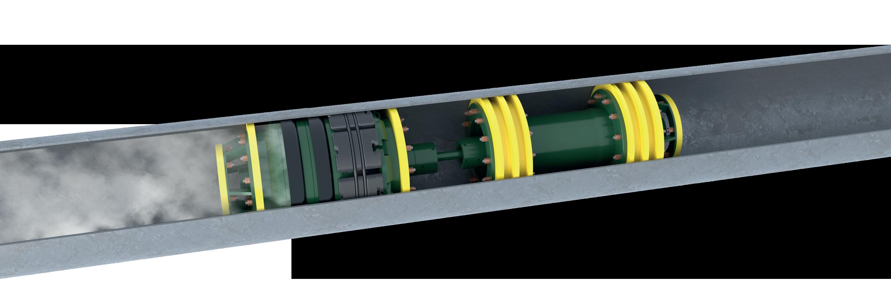
 Figure 1. Elliott 140 TCH pipeline compressor on a baseplate.
Figure 2. Elliott 140 TCH cross-section.
Figure 1. Elliott 140 TCH pipeline compressor on a baseplate.
Figure 2. Elliott 140 TCH cross-section.
24 World Pipelines / OCTOBER 2022
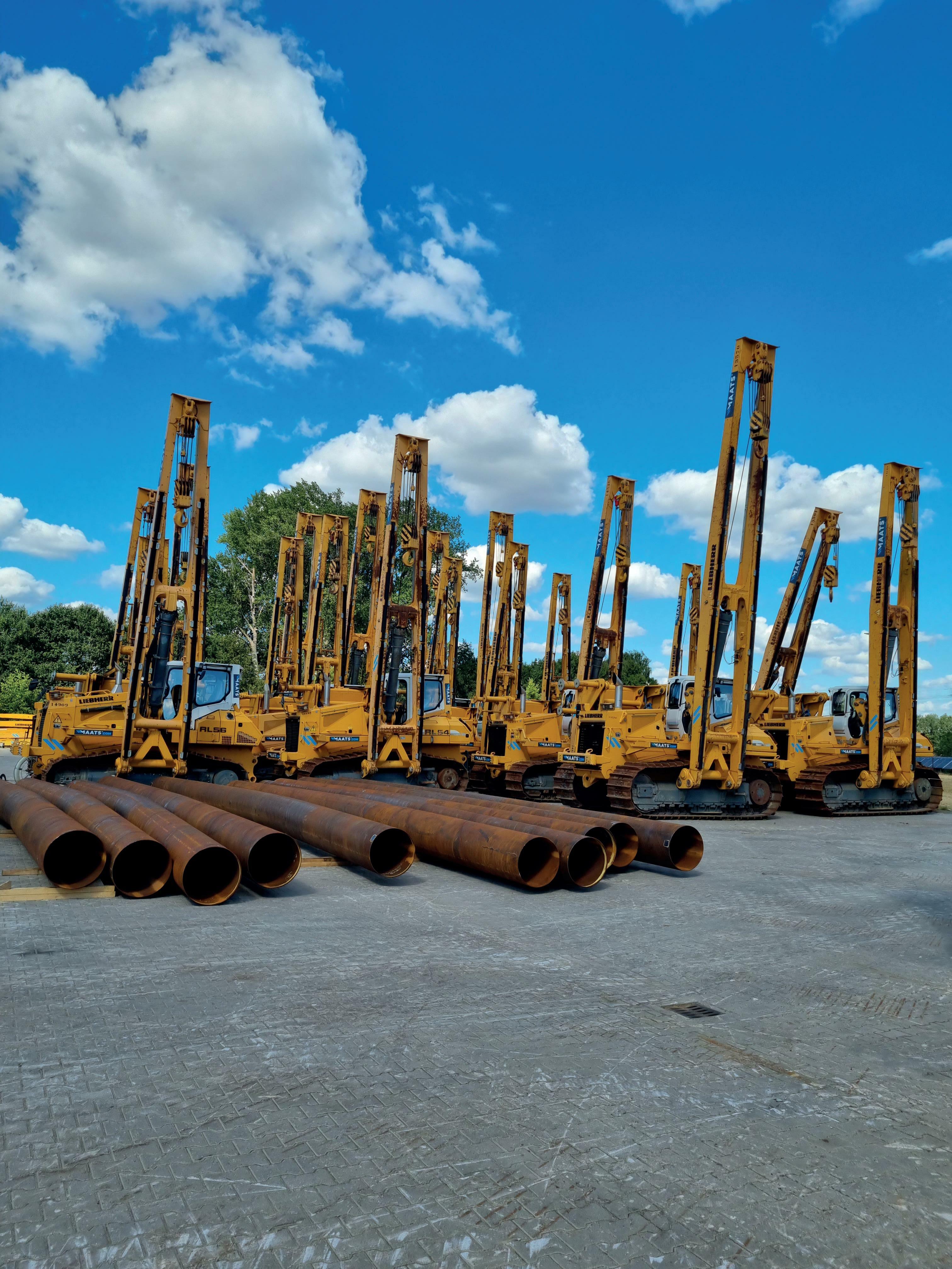

QUALITY RELIABILITY FLEXIBILITY RENTALSALES L AYING BENDING WELDING MAATS PIPELINE PROFESSIONALS P.O. Box 165 | 7470 AD Goor the Netherlands T + 31 547 260 000 F + 31 547 261 000 E info@maats.com your equipment partner since 1981 CO2 neutral rental STAAMmoc. MAATS.com
centrifugal compressors with electric motors requires the use of a gearbox in most pipeline applications.

Electric, motor-driven centrifugal compressors have been available for pipeline compression since the 1960s, but they were originally neglected by the industry because of the need to install additional electrical infrastructure on the pipeline. However, due to stricter environmental compliance regulations, centrifugal compressors driven by electric motors have become more popular over the last 15 years and now represent approximately 50% of all new, installed mainline pipeline compression equipment. This trend is continuing with an increased focus by the pipeline industry to reduce GHGs, carbon dioxide, and methane emission point sources.
Electric, motor-driven centrifugal compressors are available from low, single-digit power to well above 100 000 hp
applications. There are several technical options to electrically drive a centrifugal compressor for pipeline service. These include fixed speed, variable speed using a VFD, variable speed using a hydrodynamic coupling, direct drive, and indirect drive using a gearbox. Since pipeline service by nature is highly variable in throughput, variable-speed solutions are preferred over fixed-speed drivers to avoid the need to recycle gas, and to maintain a high efficiency over a wide operating range. Also, gearboxes add complexity and cost to the design while reducing reliability. However, since many centrifugal compressors designed for pipeline service were speed matched to be driven by gas turbines, they usually require a gearbox when driven by a conventional electric motor. It is important to note that this is a design decision that can be avoided if a centrifugal compressor is designed from its outset for a lower speed driver, such as a synchronous or induction electric motor.

To meet the demand of new compression for the replacement of old legacy compressors and the increased power demand for natural gas, the industry needs a simple, reliable, and highly efficient electric motor-driven compressor that is optimised for pipeline service.
The Elliott 140 TCH pipeline compressor addresses some of these shortcomings with features that were specifically designed for the natural gas pipeline service. This compressor uses a 1 - 2 stage impeller overhung design to reduce the number of bearings and seals. It does not require a balance piston, has an axial inlet for optimal aerodynamic performance and reduced leakage, and is speed matched to conventional, induction electric motors without the need for a gearbox.
Elliott 140 TCH pipeline compressor
Elliott has successfully provided centrifugal compressors for the oil and gas industry for over 80 years, including hundreds of machines in the pipeline or midstream service. The Elliott 140TCH (Figure 1) is derived from Elliott’s many years of experience with overhung compressor designs, but it has features that are specifically designed for optimised, natural gas pipeline service.
The Elliott 140 TCH is a single or dual-stage, overhung design with an axial inlet that is electric motor-driven without a gearbox (Figure 1). This design approach results in higher efficiency, reduced leakage from a single, dry gas seal, and the avoidance of a balance piston. The 140 TCH comes with a direct connect, variable speed (VFD) motor and a standard footprint, in addition to custom
Figure 3. Elliott 140 TCH pipeline compressor operating range.
Figure 4. Elliott 140 TCH package and maintenance access.
26 World Pipelines / OCTOBER 2022
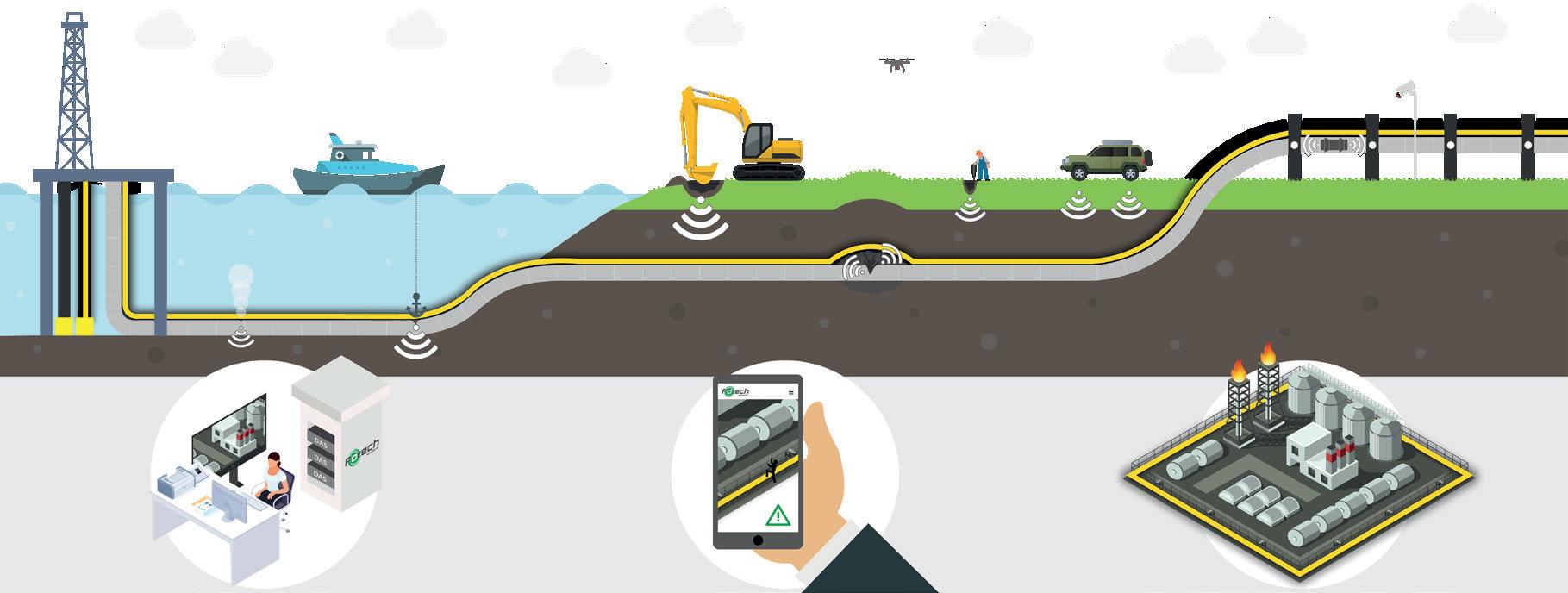

Harness the power of fibre optics to gain real-time visibility of your pipeline network with LivePIPE®II www.fotech.com team@fotechsolutions.com +44 1252 560 570 One system – multiple benefits • Detect and locate smaller leaks faster • Monitor third parties and avoid mechanical damage • Locate and prevent product theft attempts • Monitor pigging operations To find out more, call our experts on +44 1252 560 570 or email us at team@fotechsolutions.com
aerodynamics for optimum efficiency and extended operating time between scheduled overhauls. The gearless configuration provides several advantages including a smaller footprint, reduced lube oil requirements, and higher net efficiency. The high-speed VFD-powered motor significantly reduces CO2 and NOX emissions as compared to a gas turbine driver. The VFD addresses starting issues and allows for adjustable operation to match load/capacity requirements. The pipeline compressor’s single lift plug-and-play design includes auxiliaries such as lube oil, a buffer gas panel, and integrated, customised controls. Piping and wiring are included on the skid. The Elliott 140 TCH pipeline compressor is available from 10 000 - 42 000 hp to accommodate the full range of gas transport applications.
The 140 TCH is designed to handle most modern, mid-size and large pipeline compression applications. Its design is lean and simple, and focuses on making pipeline compression efficient, reliable, and cost-effective. The impeller aerodynamics are based on Elliott’s advanced and proven EDGE technology. With the axial inlet and flexible or customisable aerodynamic design, efficiencies of greater than 85% can be obtained. The direct drive compressor, with a variable speed electric motor, provides a wide operating range, including efficient turndown operation. With three standard frame sizes, 15MW, 25MW, and 35MW, the centrifugal compressor is designed for applications up to 7000 million ft3/d with a pressure ratio ranging from 1.15 - 1.8. The typical operating range for the 140 TCH is shown in Figure 3.
The machine design philosophy allows for simpler installation with a standardised package, an axial inlet, and selectable discharge

for right or left piping configurations. The package includes an integral lube system for the compressor and motor, a simplified buffer or seal gas panel (the compressor only has one seal), an on-skid control system, and all compressor piping and wiring included on a single-lift skid for reduced footprint and weight. The compressor internals are contained in an inner-barrel design and can be removed from the driver side. This allows for easy maintenance and removal of the compressor internals without the need to move any piping. The removable barrel also allows for quick and easy, installable spare bundles or compressor restaging to change aero components, as needed (Figure 4).
The 140 TCH is designed to increase reliability by minimising component count. The compressor design allows for a direct drive electric motor, which does not require a gearbox, making the footprint small and light. The axial inlet and overhung design allow for a single seal. This results in a simpler, more reliable design with reduced emissions. The balance piston and balance piston line have been eliminated, further increasing reliability and reducing losses, which leads to increased efficiency.
With a clean and simple design and industry-proven components, the reliability, availability, and time between maintenance intervals has been increased. To meet modern pipeline compressor requirements for efficiency, reliability, and low emissions, Elliott has responded with a state-of-the-art pipeline compressor, incorporating years of experience and evolution into the design of the 140 TCH. This compressor is ideally suited to meet the increased capacity demands of modern pipelines efficiently with minimal GHG emissions.
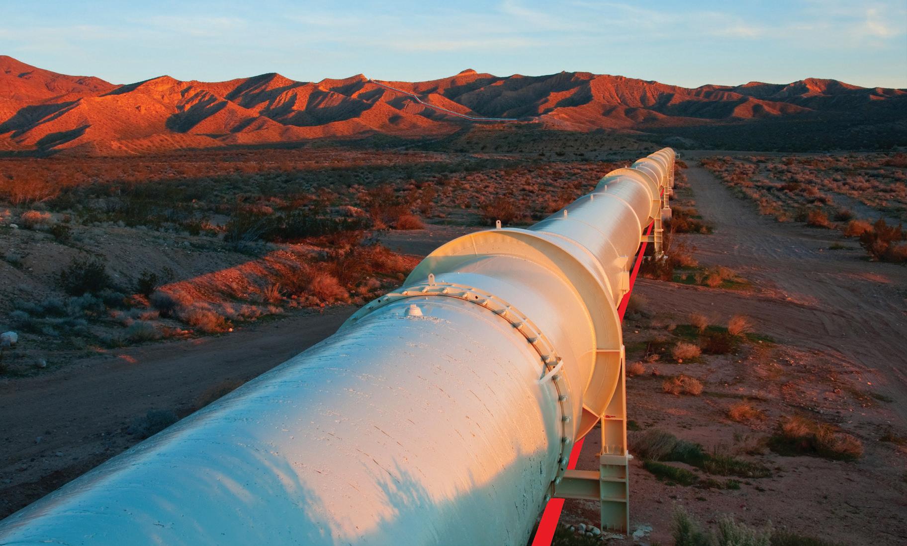
IPLOCA - encouraging sustainable energy transitions in the pipeline industry visit www.iploca.com to find out more International Pipe Line & Offshore Contractors Association Geneva - Switzerland
s natural gas moves from well sites to end users along a pipeline, friction, travel distance, and elevation changes slow gas movement and reduces its pressure along the entire line. Compressor stations are placed strategically along the pipeline to maintain the pressure and flow at an operable level. The stations are an integral part of the network, and the compressors must perform this critical task with high reliability and little maintenance requirements.
To gauge the importance of compressor stations for the gas industry, the US relies on a network of over 480 000 km of gas transmission pipelines. Typically, a compressor station is required at intervals of between 80 and 160 km, so many thousands are in operation across the country.
Historically, compressors have utilised gas or steampowered turbines to maintain the natural gas pressure. Currently, some 90% still utilise this technology. However, these turbines produce high greenhouse gas (GHG) emissions, offer low efficiency, and are hard to maintain, especially in remote locations. Since a typical compressor station will require 10 MW or more, there is now a clear incentive to seek more energy-efficient alternatives. That is why there is now a growing trend to adopt electric drivetrains, both for newbuild projects and for upgrades of existing stations.
It is not only a question of saving costs through energy efficiency. Following the COP26 climate summit in late 2021, political leaders expressed a renewed focus on reducing
 Anand Jha, Vice President of Global Sales for Chemical, Oil & Gas, ABB, USA, outlines a compelling alternative for pipeline gas compressors.
29
emissions and setting targets. As a result, most European countries and North America have set net-zero targets in their policy documents.
Whereas in the past, pipeline operators could have been tempted to stick with gas turbines since gas was the most accessible energy source, the political commitment to net-zero is compelling them to change tack. Since they now get penalised for GHG emissions, many of the world’s top oil and gas companies have set goals to eliminate such emissions from energy consumption and operations by 2050.
Electrical drive systems
The traditional approach to gas pipeline compression is to use natural gas to fuel a large, stationary engine driving a turbine. An electrical drivetrain uses very much the same principle, but with the gas engines substituted by an electric motor operated by a variable speed drive (VSD).
One of the main reasons for using gas compression was that it uses a fuel readily available from the pipeline itself, while compression stations were often located in areas where there was no electrical infrastructure. That has changed in recent years with electrification becoming much more widespread, even in remote rural locations.
The primary function of VSDs is to control the speed and torque of the motor driving the compressors. VSDs are positioned between the electrical supply and the motor. Power from the electrical supply goes into the drive, and the drive then controls the power being fed to the motor.
Converting the incoming AC electrical power to DC power smooths out the electrical waveform and adjusts the frequency and voltage based on current process demands. This means operators can run an AC motor at the speed or
torque dictated by the demand, resulting in considerable savings.
Energy-efficient benefits of VSDs
Running a compressor at full speed and controlling the flow rate and destination by manually opening and closing the valves makes the start-up process highly labourintensive. Starting up a gas compressor station can also be a time-consuming process – the labour costs add up when personnel have to travel long distances to remote sites, although this is an automated process in some facilities. But energy consumption is poor.
Running these applications with VSDs is a more cost and energy-efficient alternative, as it brings instant savings in energy consumption. The actual energy savings depend on the specific application: since the relationship between motor speed and energy consumption is non-linear, even a slight speed reduction can result in 25% or more energy savings. Startup is also usually only a matter of seconds.
VSDs also bring long-term competitive advantages like low maintenance costs, reduced waste and CO X and NO X emissions, increased production hours, and even lower ambient noise emissions. These all play a vital part in meeting environmental goals.
Other factors to consider in favour of electric drives are the capability to benefit from the high reliability and excellent control properties of the electronically adjustable AC drives and the need to avoid GHG emissions.
The advent of electric compressors
The oil price collapse of 2014 forced changes upon the gas pipeline market, including capital cost reductions and downsized budgets. But even as energy costs increase, as is currently the case, the need to achieve a good return on investement (ROI) on infrastructure remains as valid as ever.
The excessively high operational expenditure of gas turbines in terms of maintenance prompted operators to pay closer attention to the cost aspect. They started looking for an optimised solution focusing on the total cost of ownership (TCO) and not just the initial cost.
This, together with stricter environmental regulations, saw electricdriven compressors entering the market in the early 2000s. Carbon tax and credits and investors’ environmental, social,
 Figure 1. The Troll A platform features electric compressors driven by high-voltage 40 MW motors.
30 World Pipelines / OCTOBER 2022
Table 1. Comparison of gas turbine and electric drive characteristics
Compared feature
G as turbine Electric drive
Efficiency Low Very high
Investment cost High Medium
Maintenance High V ery low
Reliability/availability Medium High
Mean time to repair
A factor to consider
Low - 4 hours
Pollution/emissions High None
Speed control range Limited
Wide and easily adjustable

Speed control accuracy Medium High
Design flexibility Low High
Torque pulsation
Starting time
Low
Medium - minutes
A factor to consider
Low - seconds
Noise level High Medium
Impact on power supply Not applicable
Total life cycle cost (LCC ) Depends on energy costs
and governance (ESG) demands added to the sector’s shift towards decarbonisation.
However, since gas turbines usually operate in remote areas, electricity supply was regarded as an initial hurdle, but with advanced technology, this is no longer the case. A good example is the Troll oilfield in Norway’s sector of the North Sea. The operator, Statoil, was looking to boost production on the giant Troll A platform by installing two compressors.
Requires investigation
Depends on energy costs
ABB’s solution brought together two ground-breaking technologies: the world’s first high-voltage DC power-fromshore connection to a platform and the first commercial installation of very high voltage synchronous motors, each with a power rating of 40 MW.
The solution takes 132 kV power from the mainland grid and turns it into DC at a converter station at Statoil’s gas processing plant. Two HVDC Light power cables, each with
a capacity of 40 MW, then transport the power at 60 kV to Troll A 70 km away. There, a compact, lightweight converter station turns the power back into AC, which then feeds to the two ABB motors that drive the compressors.
This method of supplying power to the compressors was better than the conventional solution of installing gas turbines on the platform because the capital, operating, and maintenance costs were significantly less. With no penalties to pay for exhaust and maintenance costs, payback for the total investment of US$270 - 280 million happened in less than three years. The solution also reduced the environmental cost of running the compressors by 230 000 t of carbon dioxide a year. The compressors are expected to extend the field’s productive life to 2063.
Replacing a gas turbine with an electrical drive
With the push towards decarbonisation, most new compressor installations use electrical drives. While in some installations they might require a higher initial investment than gas turbine drives, their real benefit is seen over the operational life of the station. The reason is that electric drives have much lower operating expenses, leading to significant savings, especially when they’re factored in early in the plant’s design. With the right knowledge and assistance, it can also be relatively straightforward to replace an existing gas turbine with an electric system.
The main steps to assess feasibility are a torsional analysis, mechanical calculations, checking the turbine’s foundation to see if an electric motor will fit, and whether there’s a need for an intermediate frame. These steps are followed by harmonic studies, string analysis, control and power interconnection analysis, and piping.
Next in line is installing the electrification hardware, which includes the electrical house, switchgear, power and VSD transformer, MV and LV distribution, and the drive train with motor and drive. The final steps in the replacement process are process control and instrumentation integration, concluded by project commissioning.
Efficiency gains and TCO
The energy conversion efficiency of a gas turbine is typically about 47% and this is only reached at peak performance. Conversely, a corresponding electric drive system achieves around 95% efficiency over quite a wide range.
In addition, the downtime of a gas turbine is costly, with multiweek shutdowns to repair mechanical wear and tear. The average maintenance interval for gas turbines could be six months or 4000 hours.
On the other hand, electric drives offer much more efficiency and less downtime. Even if they do go down, maintenance will require a few hours or half a day at most. The electric drive system typically has an availability higher than 99.9%.
With all these factors considered, using an electric-driven turbine could enable an operator to increase the uptime of their compressor station by approximately ten days a year. This results in significant savings by reducing lost productivity. Overall, electric drive trains (VSD and motor) can save
significant operational costs, with a typical payback time of one to three years. This might even be reduced to a few months when the opportunity cost of selling the gas saved by electrification to the market, or using it in other processes, is included in the return on investment (ROI) calculation.
Recent successes: North America and globally
Over the past decade, ABB has helped operators in North America to electrify their gas compression stations in order to increase reliability and flexibility by supplying electrical drive systems ranging from 4 to 29 MW. Although globally, ABB also has proven references and the capability to offer VSD packages above 30 MW. In a typical example, ABB was appointed to replace the existing equipment at a compressor station and upgrade it to higher horsepower while maintaining the existing maximum operating pressure. The objective was to utilise the existing infrastructure and enhance the pipeline’s output capacity.
ABB supplied an ACS5000 liquid-cooled medium voltage drive with a 36-pulse oil type isolation transformer and a fin-fan cooler to drive a high-speed compressor application (0 - 167 Hz). The ability to situate the converter transformer outside the electrical house, and the efficient liquidcooled design of the drive, has reduced the HVAC cooling to a minimum. This has resulted in significant capital and operational cost savings for the project and asset.
Later, ABB supplied another ACS5000 liquid-cooled medium voltage drive for another compressor station This project resulted in a considerable cost saving, as it was possible to reuse an existing transformer and fin-fan cooler.
A critical element in these projects has been the capability to work with different local compressor manufacturers to develop and engineer solutions tailored to suit the requirements of individual locations. This has enabled operators to receive a flexible solution, rather than having to take off-the-shelf equipment.
The critical nature of the compressor stations has also placed a major emphasis on service, especially in enabling on-time commissioning within very tight deadlines. This has been made possible by ABB’s network of service engineers located across North America. The aim is to ensure a rapid response onsite in the unlikely event that a drive should ever go down.
To take service to the next level, talks are ongoing with operators to discuss approaches for remote condition monitoring of compressor stations. This will enable proactive servicing to be scheduled before any issue develops into a fault.
The future is all-electric
The simplicity of implementing an all-electric drive system for both new installations, or converting existing gas compressor stations, and the added safety and operational benefits, make it a highly compelling choice. The short payback time, reduced fuel consumption and GHG emissions lead to substantial savings in operating expenditure. In this context, the reduced environmental impact of electrification becomes a highly prized added benefit.
32 World Pipelines / OCTOBER 2022


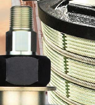
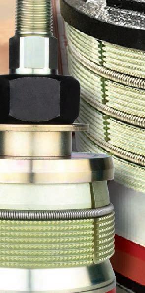
hen it comes to isolating gas distribution pipelines, there are routine challenges, and then there are extraordinary ones. And sometimes – perhaps surprisingly so – those problems have a similar root cause. And even the same solution.
One of the more common challenges is isolating a pipe that is out-of-round, or slightly oval. Although ovality is occasionally associated with third-party damage, more often it is traced back to the manufacturing process.

For decades, local distribution companies (LDC) have used a single, round, static seal to successfully isolate pipelines. In recent years, though, the concept of an ‘energised’, or expandable, seal that would be easier to insert into and retract from the pipeline became an attractive alternative. Combining a seal that could expand and adhere to the internal topography of the pipeline with the assurance of double block and bleed (DBB) would be a game changer.
Especially for those pipelines with extreme ovality or that are not perfectly round.
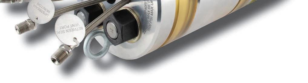
That concept became a reality in 2020. That’s when global solutions provider T.D. Williamson (TDW) introduced ProStopp® DS isolation technology, the gas distribution market’s first and only low-pressure DBB isolation equipment with an energised seal.
Widely accepted technology
Because of its DBB feature, ProStopp DS technology ensures total leak protection on
For ‘run of the mill’ and unique challenges, Ryan Ragsdale, Senior Product Manager, T.D. Williamson, USA, presents an isolation solution for gas distribution pipelines.
33
in-service pipelines the first time, every time. The area between the two plugging heads is depressurised through an internal bleed port, eliminating the need for extra taps or fittings to engage the bleed functionality. That
means the ProStopp DS tool achieves double the sealing capability through a single fitting.
In addition, it includes a patented, hydraulically activated – or ‘energised’ – seal that compresses against the pipe’s inner wall, regardless of its shape or whether there are dents, gouges or irregular weld seams. The ProStopp DS also has a chip sweep function that removes excess cutter shavings that could interfere with the seal. What’s more, the seal can accommodate multiple wall thicknesses and can be used over and over again, reducing the need to replace consumable parts. All of which makes the ProStopp DS an ideal solution that’s gained strong market acceptance in just two short years.
For example, when TDW Partner Channel Onstream Pipeline Solutions (OPS) isolated a slightly oval 12 in. gas distribution pipeline near Antwerp, Belgium, it was one of the 300-plus times the technology has been put into action since 2020. “OPS invested in 12 in. ProStopp DS technology because it is universally applicable on 12 in. pipelines and is insensitive to ovality,” Danny Vreys, OPS General Manager, said. “The result was perfect, a 100% seal on the primary and secondary plugging heads.”
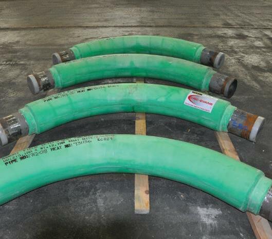
But it’s not just routine challenges that the tool is well suited for. As the operator of a gas distribution system in Florida, USA, recently learned, its flexibility also makes ProStopp DS technology appropriate for jobs that present extreme challenges. Including the isolation of a 10 in. pipe that had gotten out-of-round in a very unusual way.
In the thick of things
TDW hot tapping and plugging (HT&P) technicians are always prepared for the unexpected. When they arrived at a Florida jobsite to isolate a 10 in. gas distribution pipe prior to rerouting, though, it was with the understanding there was nothing abnormal about the 0.375 in. thick pipe wall.

As soon as they cut the coupon to allow access into the pipe, a different story began to emerge.
Instead of being smooth and uniform as anticipated, the interior surface of the coupon was covered with a thick and rocky substance that appeared to have passages cut through it. The technicians reasoned that the rest of the pipe was in similar condition.

What could have created the black, pitch-like overlay?
Keelan Prewett, the TDW Application Engineer on the project, said the problem stemmed from what is usually a benign source: corrosion protection. “It appeared the pipeline had been treated with an asphalt/tar internal anticorrosion coating that had hardened and become uneven over time,” Prewett explained. While that was concerning enough, even more troubling was the fact that more than an inch of the coating had pooled along the bottom of the pipe, although the full extent of that issue wasn’t apparent at first. Together, the coating and gas buildup had made the pipe out-of-round for a reason like no other.
Well-equipped
Although the unusual internal diameter surface condition would have taxed most static seal isolation equipment,
Figure 2. More than an inch of coating had pooled and hardened at the base of the pipe interior, introducing ovality and making the isolation more challenging.
Figure 1. The interior surface of the coupon was covered with a thick and rocky substance that appeared to have passages cut through it.
34 World Pipelines / OCTOBER 2022
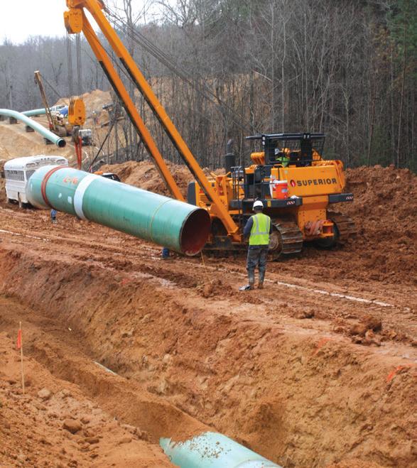
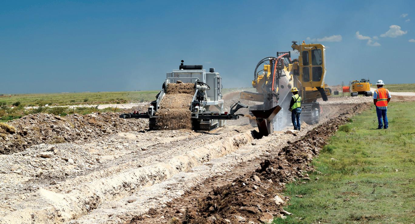
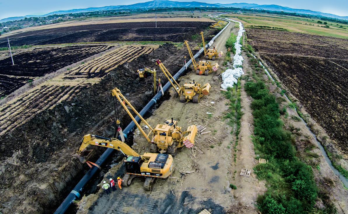
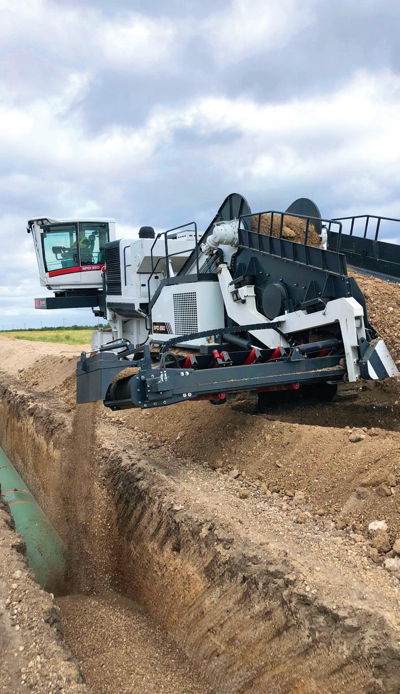
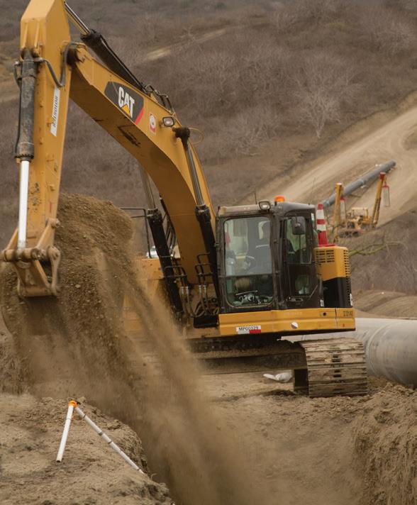
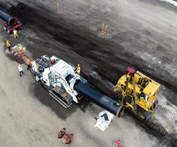
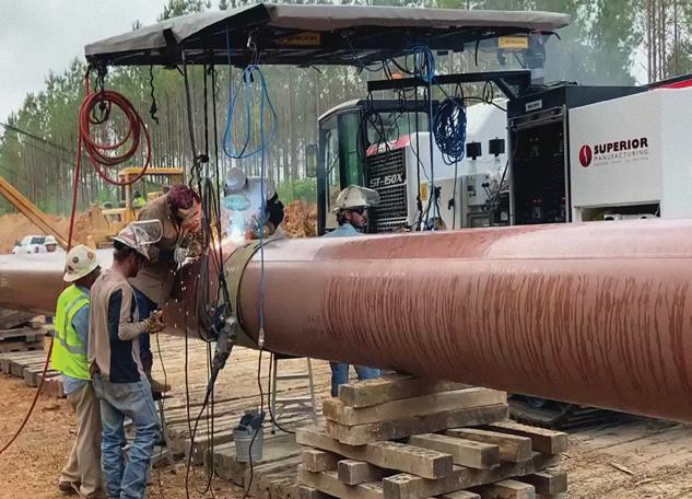

SUPERIOR RESULTS • Large and diverse inventory • On-site support • Cross-border logistics • Rental, Purchase, RPO, and Lease Options +1 800 383 2666 + sales@wwmach.com + worldwidemachinery.com/SUPERIOR SUPERIOR Manufacturing is a trademark of Worldwide Machinery
HT&P technicians knew this was where the ProStopp DS tool had a distinct advantage: its energised seals could conform effectively to the uneven pipe wall.
Still, given the strange conditions, the crew consulted with TDW Services Application engineers about how to best ensure a successful isolation. The engineers advised following standard operating procedures and starting the isolation at standard hydraulic operating pressure, then incrementally elevating until it reached maximum hydraulic operating pressure, 172 bar (2500 psi). This would exert more force to compress the sealing elements against the pipeline’s rocky walls.
Insertion and chip sweeping operations were performed without issue. The technician energised the plugging heads, and the operator blew down the isolated section. However, after the blowdown was complete, the lower explosive limit (LEL) sensors indicated there was still a small amount of gas present downstream of the plugging heads.
A sneaky leak path
Normally, any gas that escaped the isolation tool’s first seal would be safely bled off through a port – that’s the entire purpose of DBB technology. The fact that the LEL sensors were detecting gas suggested there was another leak path.
Without seeing exactly how deep the residue was at the bottom of the pipe, TDW engineers theorised the gas was traveling through the porous passages in the coating and getting between the coating and the internal diameter of the pipe. TDW detected the leak in two places: through the bleed port between the primary and secondary plugging heads and at the 2 in. Thread-O-Ring® fitting used for equalisation and blowdown of the isolated section of pipe.

With the isolation tool’s hydraulic pressure at its maximum level, TDW engineers recommended a customised – and somewhat unconventional – solution.
The vapour barrier solution
The ProStopp DS is engineered so any product between the primary and secondary plugging head can be bled out through the tool, up through the control bar of the actuator away from the work area to the control box used to activate (or energise) the plugging heads. The control box is directly connected to each of the plugging heads on the isolation tool and to the area between the two plugging heads. Knowing that the technician had access to the area in between the plugging heads gave the TDW application engineer an idea; using a vapour barrier seal to reduce or eliminate hydrocarbon leakage would allow work to safely proceed as planned, without pipeline shutdown or risk of explosion or fire.
To create the vapour barrier, TDW reverseengineered the system, which normally flows outward, to flow inward instead. Technicians plumbed a bank of nitrogen bottles into the bleed line through the hydraulic control box and started flowing the nitrogen back through the actuator, down the control bar and into the zone between the plugging heads. This way if there was a leak, it would be inert nitrogen, not hazardous natural gas.
Once the vapour barrier was in place between the plugging heads, the downstream LEL monitors detected no gas. Customer operations personnel determined the line to be safe and completed the rerouting activities.
The power of people
There’s no question that quality equipment was key to solving this extraordinary challenge. But even the best tools can’t perform optimally unless they’re in the right hands – in this case, the hands of skilled TDW technicians, the people Ed Guidry, Senior Director, Intervention and Isolation Product Line, calls “the face of T.D. Williamson on the jobsite”. These are the guys, Guidry said, who “get in the truck, travel around with the equipment and, when it’s time to run the equipment, are basically in charge of everything.”
According to Guidry, it’s probably safe to say that TDW is home to the most experienced HT&P technician on the planet. And that’s not hyperbole – TDW technician Jackie York has 47 years on the job. “I’d bet no one has performed more hot tap isolations than he has,” Guidry said. And along the way, York, like every other HT&P technician, has been backed by a team of application engineers. They’re the behind-the-scenes professionals who provide technical support, including guidance when something comes up that’s out of normal – or out-ofround, like a pipe with hardened coating inside.
For this unique situation, the collaboration between experienced HT&P technicians and application engineers unlocked a bespoke solution. By combining ProStopp DS technology with a nitrogen vapour barrier, TDW crews performed a safe isolation while the pipeline remained in service. That level of execution is routine for TDW, even when the project demands are extraordinary.
Figure 3. An internal anti-corrosion coating had hardened and become uneven over time.
36 World Pipelines / OCTOBER 2022
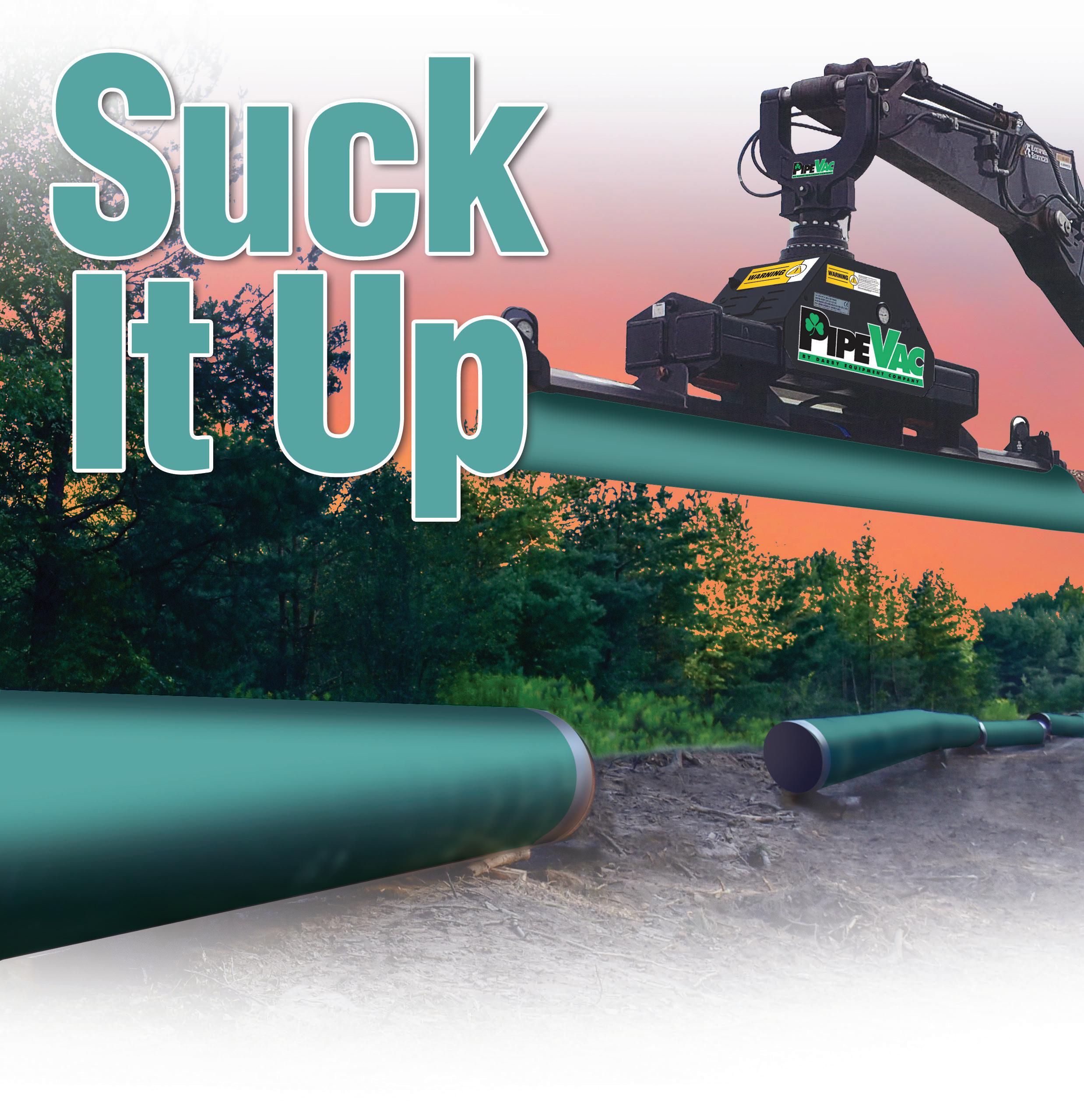
• Darbys low-flow Hydraulic PipeVac won’t bog down your machine during use • Zero Emissions • No Motor results in a quieter, safer machine with no maintenance and no fuel costs • Works in extreme conditions ExpectAHigherStandard PipeBending Machines • Pipe Bending Mandrels • Line-Up Clamps • Roller Cradles Lifting Systems • Field Joint Coating • Pipe Facing Machines • Pipeline Supplies www.darbyequip.com No Motor. No Diesel. No Downtime.
 Anne Knour, Market Communication Manager, TRACTO-TECHNIK, Germany, discusses the latest trenchless technologies and HDD assist and rescue methods for pipeline installation.
Figure 1. Directional Service South utilised a GRUNDORAM Taurus pneumatic pipe rammer by TRACTO to assist with the extraction of 360 m of 500 mm pipe.
Anne Knour, Market Communication Manager, TRACTO-TECHNIK, Germany, discusses the latest trenchless technologies and HDD assist and rescue methods for pipeline installation.
Figure 1. Directional Service South utilised a GRUNDORAM Taurus pneumatic pipe rammer by TRACTO to assist with the extraction of 360 m of 500 mm pipe.
38
renchless technology is primarily leveraged for the installation of underground utilities, creating the least amount of surface disruption possible, saving time, costs, and resources. In particular, pipe ramming and horizontal directional drilling (HDD) are favourable methods for implementing even highly complex and challenging pipeline construction projects. But when something goes wrong at an HDD jobsite and rapid action is needed, a pipe rammer is also the means of choice applying so called assist and rescue methods. This article describes the options for trenchless pipeline installation and illustrates the different HDD assist methods, including a practical example.
HDD technology for pipeline installation
HDD is one of the most complex, but most versatile and flexible trenchless technologies. Nowadays HDD rigs are standard equipment for pipeline construction projects just like excavators, hoisting cranes, and other common auxiliary tools. This ever-advancing trenchless

technology contributes a technical and economic edge as well as providing environmental and productivity advantages.
The main applications of HDD for pipeline projects are crossings underneath rivers and traffic ways (railways, highways, roads, runways, etc), flood protection dams, crossings below foundations of buildings or infrastructure objects, as well as longitudinal bores parallel to traffic and waterways, or in open terrain such as nature reserves. This flexibility is due to the HDD rig being ‘steerable’; the bore head contains a sonde to constantly monitor its position by means of a detection system, allowing the so-called pilot bore to follow any given path, and even to carry out directional corrections during drilling. Once the pilot bore has been established along the required bore path, the drill rods are retracted, and the bore channel is enlarged by an expansion head with the attached pipe pulled in at the same time.
There is a wide range of HDD rigs available on the market, ranging from Mini 1.5 t pit-launch machines
39
to Mega HDD rigs with a pullback force of 2500 - 6000 t. The principle of the directional drilling process remains the same, however high the pulling forces are. For installing pipelines with large diameters of 2000 mm and more over longer distances using HDD, 400 - 2500 Maxi rigs and Mega rigs are applied.
Ramming technology for pipeline installation
The dynamic steel pipe ramming technique plays a significant role in expanding the worldwide pipeline infrastructure for the supply of resources such as oil and gas. Mainly, pneumatically driven pipe rammers are being used for the installation of pipelines beneath roads, railway embankments, and rivers. These machines, which provide impact forces up to 40000 J enable the underground installation of open steel pipes as casing or product pipes up to 4000 mm dia., over lengths up to 80 m, in soil classes 1 - 5 (partly even class 6 – easily soluble rock) without the need for jacking abutments. Pipe rammers are suitable for installing horizontally and helically welded pipes, seamless pipes and pipes with insulation protection without tearing up valuable surfaces. Pipe ramming can can be used for various applications in all kinds of soil types except for muddy areas, swamps and compact, non-displaceable soils.
The potential of dynamic impact energy for HDD projects
Dynamic impact force is one of the most efficient methods of energy application in the construction trade. Other than static energy, dynamic impact power can move or loosen the soil or elements stuck in the ground. Thus, pipe rammers are not only used for underground pipeline construction, but also to free stuck drill rods or pipes, allowing them to be removed, relocated or mobilised

subsequently. These HDD and rescue methods can help with a variety of onsite problems, as detailed in the following.
HDD assist and rescue methods
Pipe rammers have been used in various ways on HDD projects for several decades. These HDD assist and rescue methods have been developed cooperatively between HDD contractors, engineers and trenchless equipment manufacturers. These developments have largely taken place in the USA, where HDD has long been used for largescale pipeline projects.

Pipe ramming specialist, Rick Melvin from US trenchless manufacturer TT Technologies explains: “Contractors have been using pipe rammers on HDD projects to help install pipe under challenging areas like waterways for a long time. Through the pullback assist methods, percussive force from a pipe rammer on the back end of a pipe string can help prevent hydrolock and ensure a smooth installation. Now when things don’t go as planned, a drill rod breaks or a segment of pipe needs to be removed, we can do those things as well, again using the percussive power of the pipe rammer to help remove or salvage those products from the ground.”
Considering the amount of money and time that is lost when a major pipeline installation project comes to an unexpected halt, it’s worth taking a closer look at the individual HDD assist and rescue methods, namely conductor barrel, pull back assist, bore salvage, drill rod recovery and the latest technology pipe extraction.
Conductor barrel: installation of casing pipes for HDD crossings
The concept behind the conductor barrel is creating a clear pathway through poor soil conditions so that drilling
Figure 2. Installation of three pipes Ø 48 in. (1220 mm) each on the Isle of Sicily using a 450 t Maxi HDD rig PD 450/120 DZ by Prime Drilling as part of constructing the Trans-Mediterranean gas pipeline from Algeria via Italy to Holland.
Figure 3. GRUNDORAM Apollo by TRACRO used to establish crossings underneath 45 traffic ways with DN 1220 steel pipes for the ‘Noord-Zuid’ gas pipeline running North to South in the Netherlands.
40 World Pipelines / OCTOBER 2022
Together, we create the most distinctive and integrated welding solutions for the construction of reliable and sustainable pipelines. As a family business, we think long term. Dedicated and continuously improving, we always challenge ourselves to go the extra mile. Qapqa. Joining solutions.
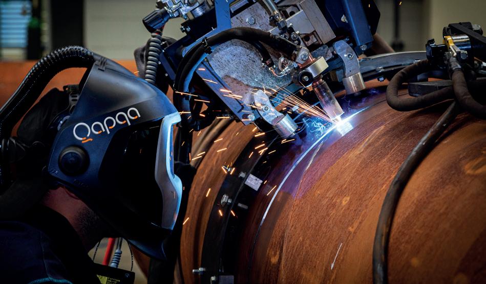
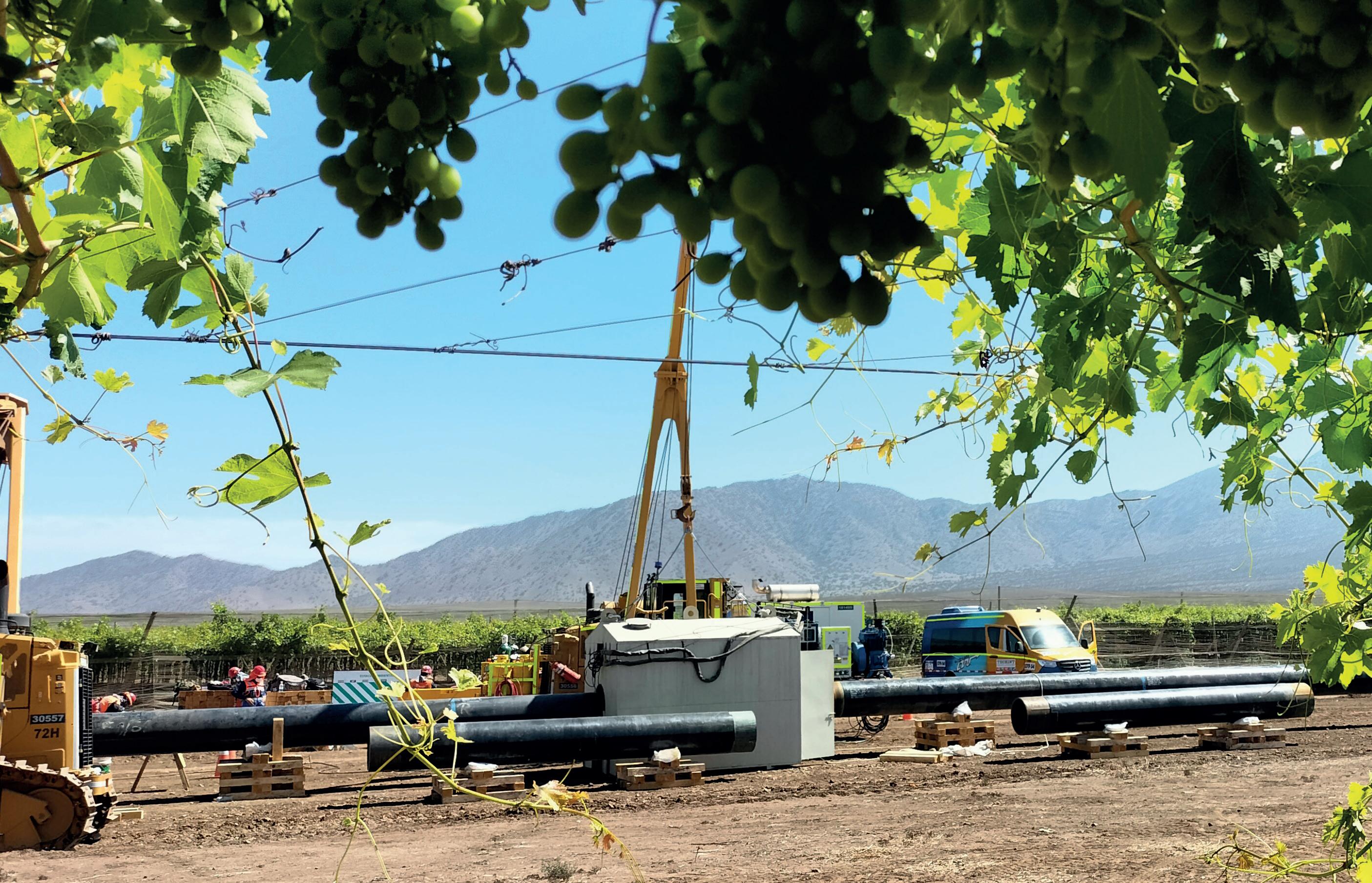
Techint project
Chili
• Increase productivity • Increase quality • Lower repair rates • High level of support
-
We will attend ADIPEC Exhibition and Conference 2022 ADIPEC 2022 | Abu Dhabi (UAE) | 31 Oktober - 3 November 2022 | adipec.com
can begin in more favourable soil conditions. If drilling does not begin in soil that is conducive to drilling, the success of the entire project can be put in jeopardy. Loose, unsupported soils are prime candidates for this method.
During the conductor barrel process, casings are rammed into the ground, at a predetermined angle, until desirable soil conditions are encountered. The spoil is removed from the casing prior to the drilling operation.

Drilling starts within the casing in the favourable soil conditions. The conductor barrel pullback assist can also serve as a friction-free section during the pullback
operation or prevent situations in unstable soils acting in a similar fashion to containment cells.
Pull back assist: overcoming hydrolock
The pullback assist technique incorporates the use of both a pipe rammer and an HDD rig working in tandem to get a problematic product pipe installed. When drilling underwater or in loose flowing soil conditions, hydrolock can occur. This happens when the external pressure being put on the product pipe from ground water pressure, drilling fluid pressure and/or soil conditions exceeds the drill rig’s pullback capacity, or the product pipe’s tensile strength. The percussive action of a pipe rammer in this situation is used to help free the jammed pipe. The pullback assist technique has been successfully used on steel pipe, as well as HDPE. This method can be used as a safety measure in anticipation of hydrolock problems, or after the pipe has become jammed.

Bore salvage: rescuing/removing jammed product pipes
This simple yet highly effective technique is used to remove jammed product pipes. During the bore salvage operation, the pipe rammer is attached to the end of the partially installed product pipe. The pipe rammer is attached to the product pipe so that it pulls the pipe from the ground. This can be accomplished through a fabricated sleeve. A winch or some form of pulling device is used to assist the rammer during operation. In many cases, the impact power of the pipe rammer is enough to free the jammed product pipe and allow it to be removed from the ground.
Drill rod recovery: loosening of jammed HDD drill rods
The principal is the same during drill rod recovery, as it is during bore salvage, however, there are two possible tooling configurations. Depending on the situation, contractors can remove the drill rod from the ground or, if the rod is still attached to the drill rig, push on the rod while the drill rig pulls back.
Pipe extraction: replacing pipes already installed
The impact force of the pipe rammer is combined with static pullback to extract an old or damaged product pipe. It is then replaced with a new pipe, allowing operators to save expensive pipe and bore again. To do so, a pipe rammer is attached to both ends of the pipe to be extracted. The percussive impact power of the rammer at one end helps free the pipe by pushing it, while the lead rammer at the other
Figure 4. Conductor barrel in practice: ramming of a casing through difficult soil conditions to gain a more favourable starting point for an HDD bore.
Figure 5. Pullback assist in progress with a pipe rammer helping to get a get a problematic product pipe installed.
42 World Pipelines / OCTOBER 2022
SEEING IS
Take a look at our ABC Certificate. It shows our circulation has been independently verified to industry agreed standards. So our advertisers know they're getting what they paid for.

ABC. See it. Believe it. Trust it. To advertise email Chris Lethbridge at Chris.Lethbridge@worldpipelines.com


www.abc.org.uk
end uses the percussive force to pull out the pipe segments, with additional equipment providing pulling force.
On the job: pipe extraction saves gas infrastructure project

On an infrastructure expansion project near Houston, Texas in 2021, HDD contractor Directional Service South had to face an unexpected challenge caused by an unpleasant incident: a sizable section of recently installed gas transmission main had been damaged during the installation by underground obstacles, and now had to be removed and replaced. Jake Gautreaux, Founder and Co-owner of Directional Service South, explains: “For this project, we were tasked with installing several miles of 500 mm steel gas transmission main with installation lengths ranging from 150 to 920 m and ScarGuard®-coated pipe welds. The whole project covered 30 HDD crossings. After one particular 360 m long installation, crews noticed an issue with some damage to the pipe. It was going to need to be replaced.”
According to TT Technologies’ Rick Melvin, pipe extraction is an evolution of existing ramming techniques developed over time. “The extraction process is really an extension of several HDD Assist methods we developed over the years using the pneumatic pipe rammer”, he says. “The things we’ve learned from salvaging stuck bores and retrieving drill stems with the help of pipe rammers have enabled full scale pipe extraction to become a reality.” The project in Houston would put that knowledge to the test.
Melvin states that, for a full pipe extraction, it’s about using the right balance of force: “In this case you need
pulling force, which can be an excavator or directional drill, combined with the percussive force of the pipe rammer. Now, these forces can be combined and applied in different ways depending on the specific jobsite situation. That’s where the complexity of the process lies. How to balance and apply the forces in a way to remove the pipe from the ground.”
The rammer’s percussive force gets the pipe moving
Back to Houston; regarding the area in question, the whole installation turned out trickier than expected. “We installed the crossing without trouble but couldn’t tie it in right away”, tells Gautreaux. “We had to spin around and install the next crossing, drilling the other way. So, we were basically sitting on top of the one we just put in. Only after we had installed that next pipe section, we were able to access that first pipe.” That’s when they noticed the damage – a large scratch ran across the whole visible pipe length and breached the coating. “A quick decision regarding the future of that section had to be taken.”
The full extent of the damage could not be considered, as a section lay underground. In agreement with the project owner, it was therefore determined that the pipe was to be removed and replaced. The new pipe would furthermore be completely wrapped in ScarGuard® to help prevent any possible damage.
When the extraction works began, the pipe had already been in the ground for two months. “The wrapping on the welds is abrasive and creates friction, which made pulling the pipe out extremely difficult”, tells Gautreaux. Initial attempts to use static pull force to remove the pipe failed. “In addition, we wanted to pull in the 360 m replacement section of pipe at the same time. That’s when we brought in the GRUNDORAM Taurus rammer to complete the extraction configuration.”
The pipe ramming tool was added to the back of the pipe string, completing a rather well-constructed extraction set-up. Melvin: “What we have during extraction is pull force on the front end of the pipe and percussive force on its back end.” The crews used a 150 t, 6 part block system to channel the static pull force from a crawler track unit, doing the pulling, to the lead end of the pipe. The percussive force of the pipe rammer, in this case, was used to re-activate the drilling fluid already surrounding the pipe in the bore hole and get the pipe moving. So, the static force can be used to extract it. “You can’t pump any more bentonite”, he says. “So, you have to use what’s already down there.”
After 10 minutes of ramming and pulling, the pipe finally started moving. Overall, it took two 12 hr days to remove the pipe and pull in the replacement simultaneously. The crews were able to extract the 360 m pipe in two 180 m sections. “The hammer worked great in breaking the line free, allowing equipment to continue movement”, says Gautreaux. “That’s the reason we bought the rammer, to have it in our fleet and on the jobsite. Time is of the essence when problems arise.”
Figure 6. HDD Assist techniques with pneumatic pipe rammers have helped directional drilling projects with everything from assisting with difficult pullbacks and recovering drill stems to salvaging bore pipe and pipe extraction.
44 World Pipelines / OCTOBER 2022

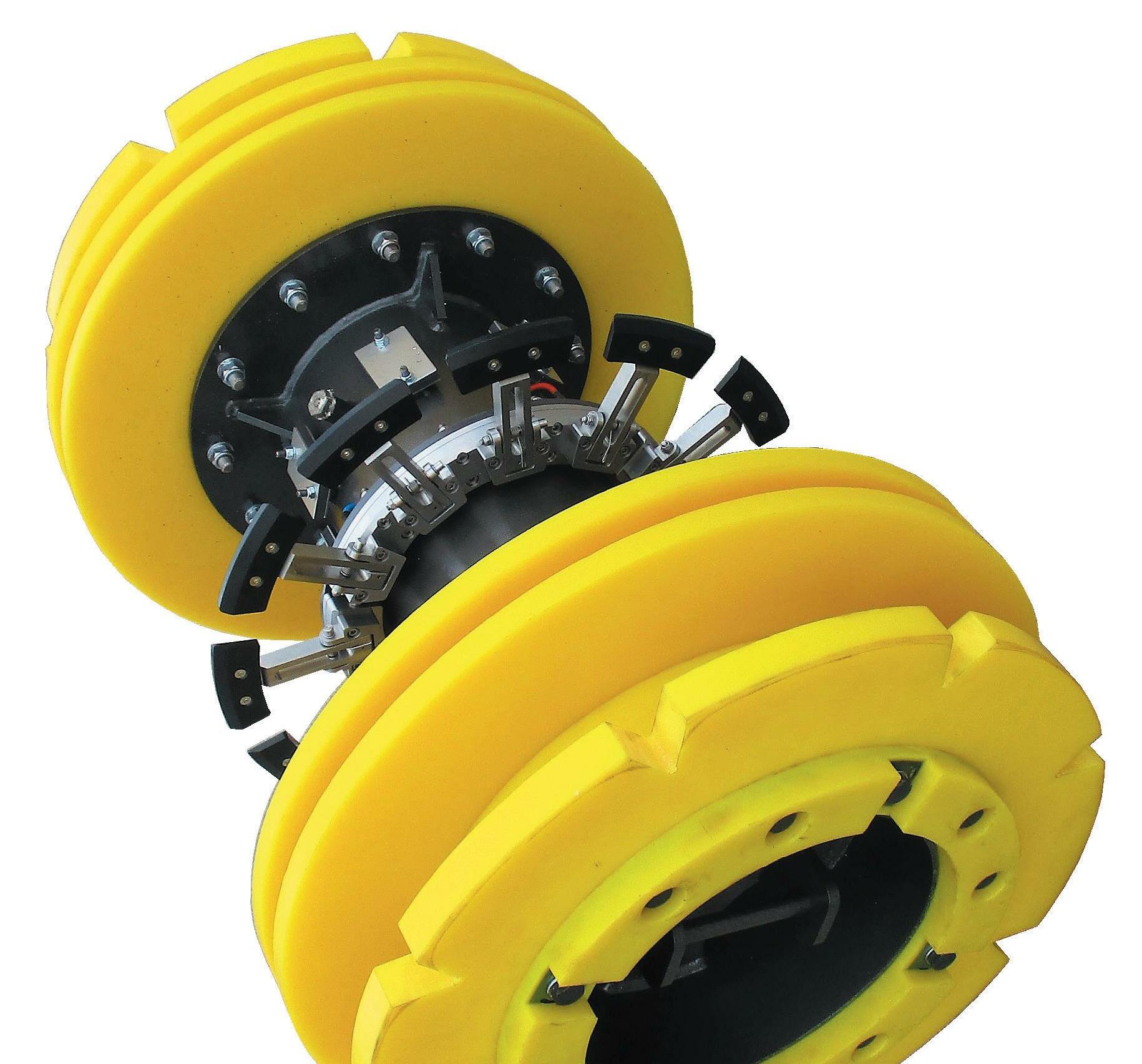
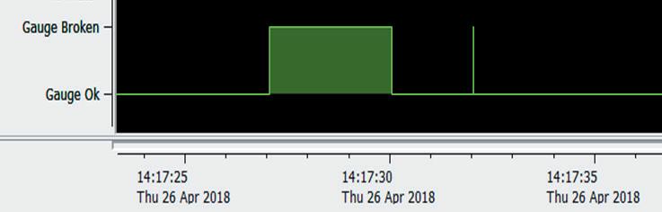
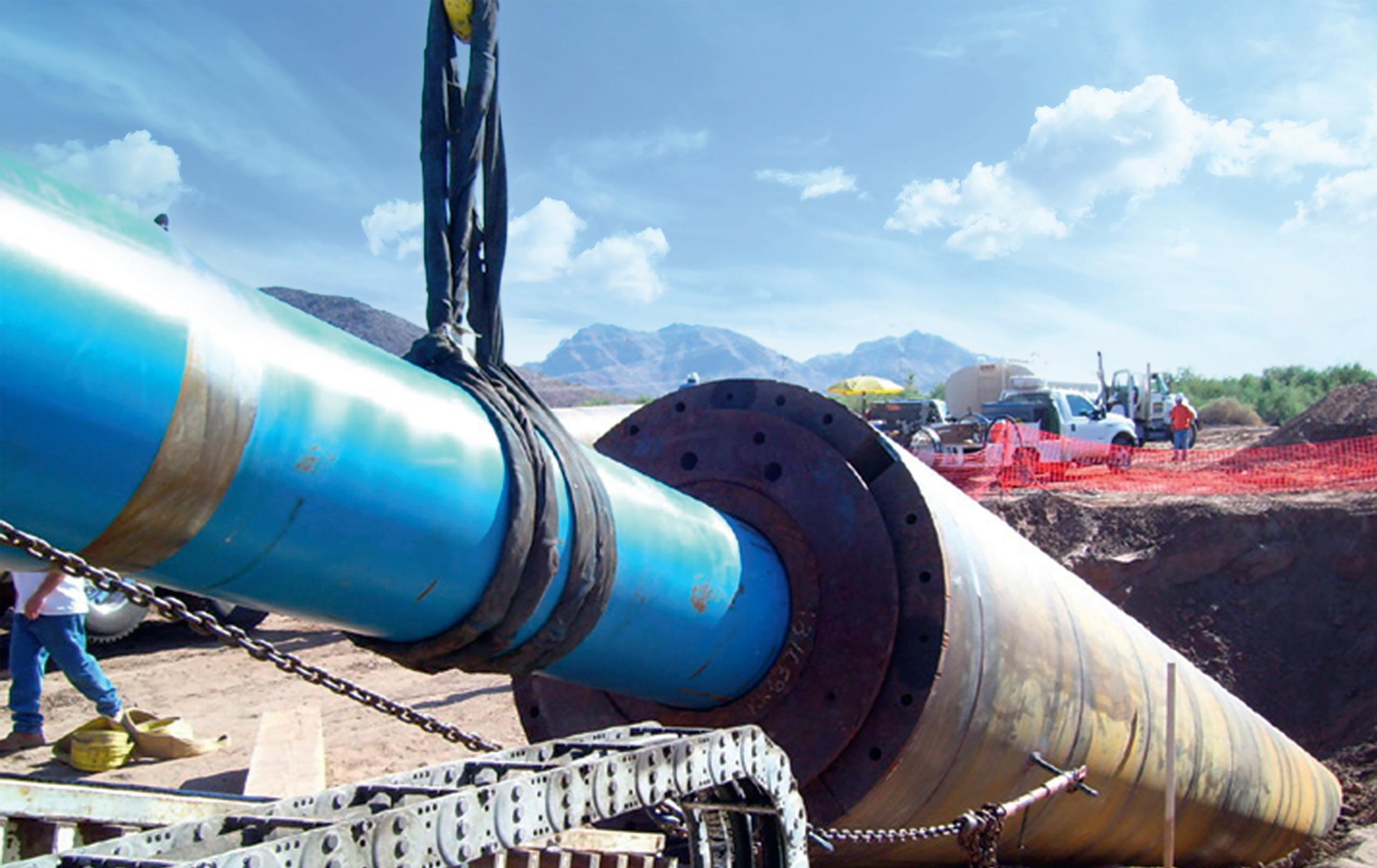
TRIDENT SMART GAUGE SYSTEMS SMART Gauge Range • Single-Hit • Multi-Hit Non Measuring • Multi-Hit Full Measuring • Through Wall Communication TRIDENT - The Future of Pig Tracking www.piggingsmarter.com GRUNDORAM – HDD ASSIST NEED A DRIVING FORCE FOR YOUR PIPELINE PROJECTS? TRACTO.COM Using GRUNDORAM rammers you can install casing or product pipes up to 4.000 mm diameter without digging trenches - saving costs, time and resources. Plus the powerful rammers can fix problems occuring during complex HDD pipeline installation projects applying HDD Assist & Rescue methods. TRACTO.COM/GRUNDORAM
range of viscoelastic tapes used for corrosion prevention on pipelines, field joints, fittings & valves.
DENSO™ are leaders in corrosion prevention and sealing technology. With over 135 year’s service to industry, our mainline and field joint coating solutions offer reliable and cost effective protection for buried pipelines worldwide.
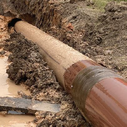
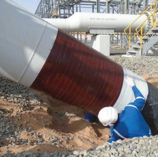
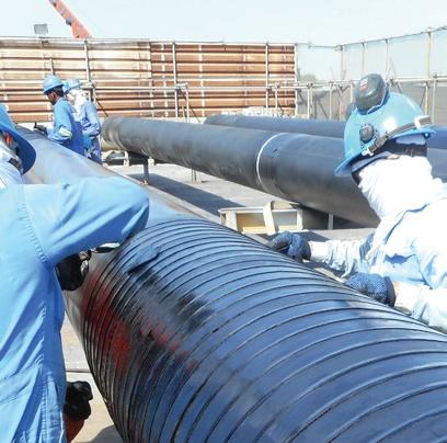
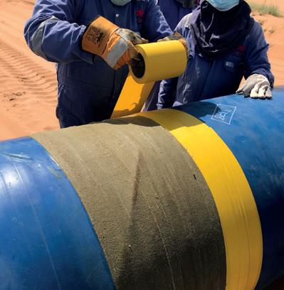
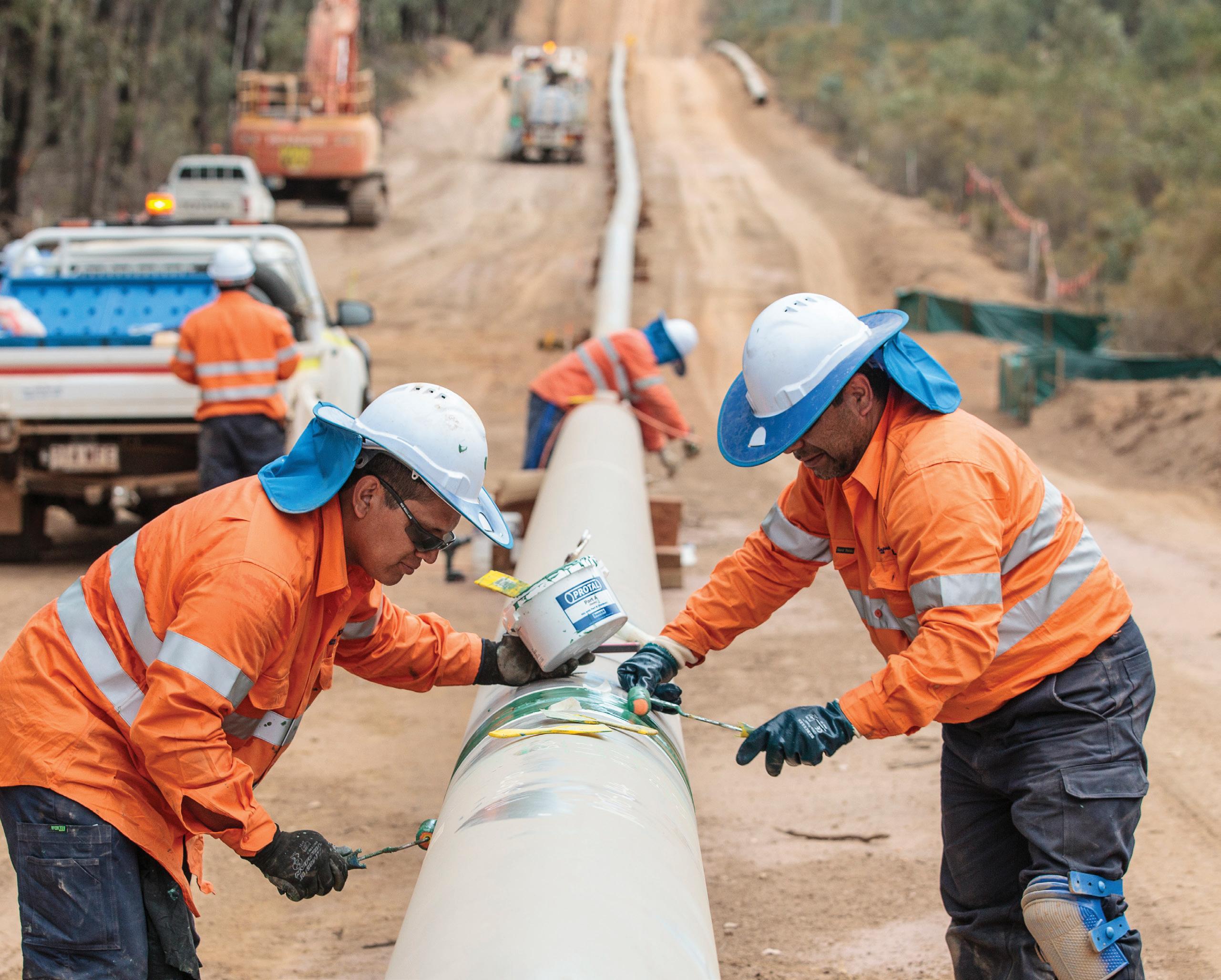

United Kingdom, UAE & India USA & Canada Australia & New Zealand Republic of South Africa
PROTECTIVE OUTERWRAPS SOIL-TO-AIR INTERFACE SYSTEMS BITUMEN & BUTYL TAPES PETROLATUM TAPE SYSTEMS PROTAL 7200™ SPRAY/ROLLER/BRUSH APPLIED LIQUID EPOXY COATING DENSO VISCOTAQ™ FOR CORROSION PREVENTION The unique, self-healing technology of Viscotaq offers asset owners outstanding, long-term protection against corrosion.
www.denso.net www.densona.com www.densoaustralia.com.au www.denso.co.za A MEMBER OF WINN & COALES INTERNATIONAL A
> >
s the number of subsea pipelines continues to increase and both the internal and external environments that they are subjected to become more severe –deeper waters, higher operating temperatures – the requirement to monitor them for unexpected movement is an increasingly critical aspect of subsea pipeline integrity management.
Subsea pipelines are often designed to withstand movement up to a certain magnitude caused by factors such as thermal expansion or challenging metocean conditions. However, excursions from intended operating limits, extreme environmental conditions, or accidental damage through external force can all result in pipeline movement that exceeds any design limits and therefore requires some form of intervention, be it further assessment, more frequent inspection, or repair.
It is a regulatory requirement in many countries to regularly monitor subsea pipelines for signs of external damage or movement so that any issues can be identified early and addressed before an ultimate limit state is reached and potentially catastrophic failure occurs.
This article will discuss the common causes of movement in subsea pipelines, how a pipeline operator may identify, measure and monitor outof-straightness and what actions may be required upon the discovery of movement outside of design limits.
 Andrew Wilde, Principal Engineer, ROSEN UK, talks monitoring subsea pipelines using internal inspection technologies.
47
Out-of-straightness in subsea pipelines

Out-of-straightness in a subsea pipeline may be part of the original design and therefore does not pose a threat to pipeline integrity. The following are examples of out-of-straightness that have their origins in the design and installation stages:
) Directional changes due to pipeline routing and installation conditions.
) Seabed topography and features (e.g. potholes, boulders and coral outcrops).
) Gravity pull where a pipeline lacks support (e.g. freespans and catenary risers).
) Crossings of existing infrastructure (e.g. pipelines and cables).
) Crossings of buckle trigger structures.
) Tie-in to pipeline inline or end termination structures.
) Crookedness of the pipejoints as per fabrication.
Many of the above upfront expected out-of-straightness situations introduce static, and in some cases dynamic, loads to a pipeline that need to be compared to stress or strain-based limits, as well as other limit states such as fatigue. Providing the pipeline is operated within its design limits, these loads should not impact the integrity of a pipeline during its design life, but may require further consideration if the life of the pipeline needs to be extended.
However, other sources of out-of-straightness may be unexpected and associated with pipe movements due to operational or environmental loadings or external impact. Examples include:
) On-bottom instability in inclement metocean conditions (e.g. severe currents during storms).
) Soil movement (e.g. by soil transportation, scour, slope instabilities and seismic activities).
) Impact by trawl boards, anchors and icebergs.
) Lateral or upheaval buckles caused by thermal expansion.
) Pipe walking (also referred to as pipe ratcheting) due to cyclic pressure and temperature loading, and gravitational pull or axial tension from, for example, catenary risers.
As pipeline movement during operation is a known phenomenon, pipeline integrity management programmes should include measures for identifying, measuring and monitoring pipeline out-of-straightness where such a threat exists.
Methods for identifying, measuring and monitoring out-of-straightness
Where the operating environment of a pipeline indicates that movement is a credible threat, the integrity management plan should set out a range of mitigation measures. Key to any effective movement monitoring plan is a baseline route profile that is established immediately following installation which can be used as a reference for future inspections. The accuracy and resolution of this baseline survey should be sufficient to allow subcritical levels of pipeline movement to be differentiated from measurement errors that result in apparent change in pipeline position indicated by future surveys.
After pipeline installation, the offshore pipeline trajectory is traditionally recorded through inspections by ROVs, towed sensors, and more recently also by AUVs. These inspections may involve a myriad of tools such as cameras, single beam, multi beam, and side scan sonar systems or sub-bottom profiling with high resolution multi-channel/multi-component seismic, magnetometers and gradiometers.
No single tool is perfect when it comes to measuring pipeline out-of-straightness, and increasingly operators are using a combination of methods in a complimentary manner. All methods have their particular advantages and limitations. The main challenges with ROVs are that they are time consuming inspections to perform, and costly because they require a sizable support vessel and skilled operators. Challenging environmental conditions can also limit their successful application and limit the quality of data that is gathered. A cost-effective alternative that overcomes these limitations, and has the prospect of providing superior measurements, involves the use of inertial measurement units (IMU) mounted to inline inspection (ILI) tools. Since the IMU will run internally within the pipeline, it is capable of recording the out-ofstraightness throughout the full length of the pipeline from launcher to receiver, and its accuracy is not affected by environmental conditions, e.g. poor visibility.
ILI is a fundamental aspect of most pipeline integrity management programmes and for subsea lines these systems are most commonly used to detect, size and monitor corrosion activity within the pipeline. IMUs can be mounted to those inspection tools, to cleaning pigs and, unless more frequent inspections are desired, do not require a dedicated inspection run.
Figure 1. Pipeline out-of-straightness caused by external impact. (Photo courtesy of US Coast Guard)
48 World Pipelines / OCTOBER 2022
coating

Midwestern’s M12H, M18H & M24H are the newest addition to our winch attachments. These winches are designed for hoisting purposes on excavators with lift capacities of 12,000/18,000/24,000 lb and attaches with a quick coupler to the excavator stick. The attachments use existing cab controls for all winch functions, ties into the auxiliary hydraulic circuit, and are easy to install.
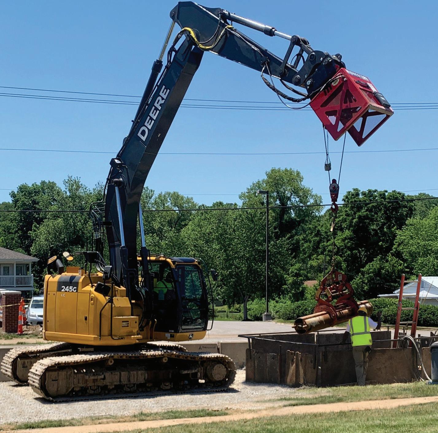
your equipment more versatile by adding on one of our hoist winches.
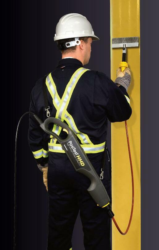
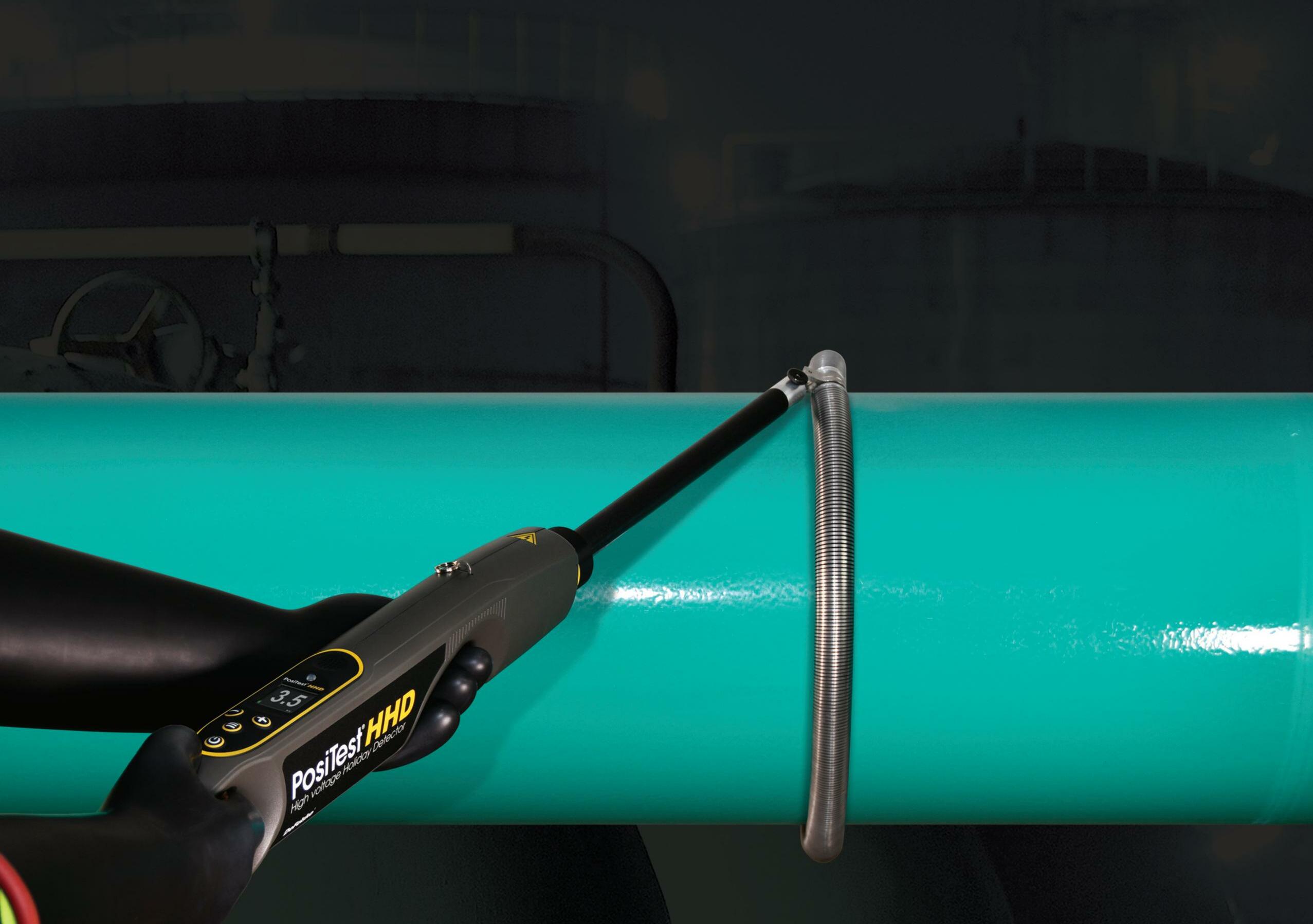
MIDWESTERN - built for the toughest jobs.

Make
sidebooms.com I 918-858-4201 Detects holidays, pinholes and other discontinuities using pulse DC NEWHigh voltage Holiday Detector Choose from a wide range of rolling spring and wire brush electrodes custom sizes available n Lightweight, ergonomic design reduces operator fatigue n Regulated pulse DC voltage output ±5% accuracy n Industr y standard connectors and adaptors for compatibility with nearly all existing electrodes n Voltage calculator feature choose one of 11 international standards, and input the
thickness to automatically calculate the required test voltage n Removable smart lithium ion batteries provide long lasting power 1-800-448-3835 www.defelsko.com Ogdensburg, New York USA l Tel: +1 315 393 4450 l Email: techsale@defelsko com Optional handheld wand accessor y converts the detector into a wand configuration ideal for testing hard to reach areas
What is an IMU and how can it be used to monitor subsea pipelines?
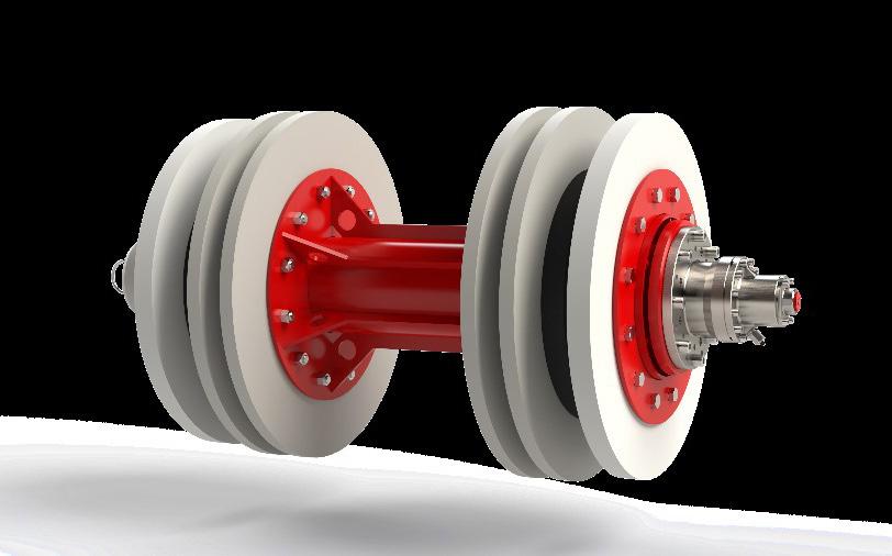
An IMU, as used for pipeline ILIs, is an electronic device that measures and reports linear accelerations and rotational rates, using one accelerometer and one gyroscope per axis for each of the three axes: pitch, roll and yaw. As the IMU only detects and records linear accelerations and rotational rates, post processing is required to compute the XYZ data points providing the pipeline profile used in XYZ mapping.
One challenge of using IMU measurements for global pipeline XYZ mapping is that positional errors are accumulated over time, leading to a ‘drift’: an ever-increasing difference between the calculated location and the actual location. As a result, in order to determine an accurate pipeline route (within say 0.7 m) regular tie-in points are required, typically every 1 - 2 km. For most onshore pipelines, establishing regular tie-in
points is economically viable, and so ILI using IMUs has become a standard practice for establishing an accurate profile. For subsea lines however, this requires the use of ROVs which negates many of the benefits of using ILI to map the route of subsea pipelines, and so the use of IMUs for subsea pipelines for pure mapping with high global accuracy is less prevalent.
However, once an accurate baseline route has been established, typically through ROV or AUV inspection following pipeline construction, the focus for future inspections is on identifying and quantifying any changes to the pipeline route that may have occurred due to excursions from design limits or external impact. This requires an accurate indication of the pipeline trajectory/curvature over a localised area, and is not dependent on an accurate absolute position of the pipeline. Where repeat inspections using IMU are available, changes in pipeline curvature can be identified, and these areas can be reviewed in more detail to determine whether the differences in pipe curvature have been caused by pipeline movement. By applying virtual fix points at the start and end of the suspected pipeline movement area, the direction and extent of movement can be determined. Using this approach, movements of the magnitude 0.2 m can be detected. For pipe sections with established pipe movements, the pipeline movement pattern will be assessed for characteristics that may reveal the movement root cause, e.g. pipe walking, anchor drag or freespan developments. By analysing for such characteristic movement patterns, movement of significantly less than 0.2 m can be identified. Furthermore, if the pipeline movement can be determined to be predominantly displacement controlled, the pipe curvature may be converted into bending strains and criticality checked against code allowable strain limits vs the more strict stress limits. Consequently, pipeline movement can be identified, quantified and assessed using IMU without the need to establish regular tie-in points, and therefore provides an effective solution for susceptible subsea pipelines.
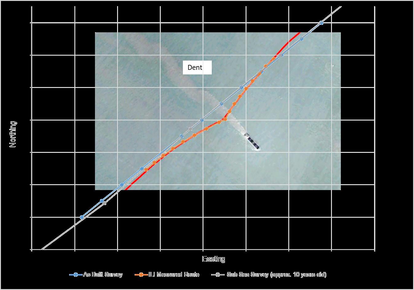
Deployment of IMU tools
IMUs are normally deployed as part of an ILI combo tool including, for example, magnetic flux leakage and geometry sensors. This combination of inspection technologies can provide a wealth of information to support integrity assessments, especially in cases of coincident damage.
Figure 3. RoGeo Tool.
Figure 2. Comparison of repeat pipeline trajectory data.
50 World Pipelines / OCTOBER 2022
This was evident following a recent internal inspection of a predominantly onshore pipeline with an estuary crossing several kilometres long, where shipping activity was high. A large dent (>6% of the outer diameter) was reported on the top/side of the pipeline. The dent was subject to an initial integrity assessment which demonstrated a low likelihood of cracking due to localised curvature strain, and showed that the fatigue life of the dent exceeded the design life of the pipeline. However, its location within the estuary warranted further investigation to determine its root cause. The internal inspection had used a combination of MFL, caliper and IMU technologies, although IMU data had been used only to map the onshore pipe section. A comparison of the local pipe profile as indicated by the ILI against both the as-built survey and an in-service ROV inspection showed a clear deviation in pipeline route, centred on the dent location (Figure 2). Subsequent analysis of the pipe curvature indicated global bending strains approaching 2% that were coincident with both the dent and a girth weld. Movement in excess of 20 m was identified. Although no metal loss was identified by the MFL tool, further analysis will be required to fully quantify the peak strains that the pipeline has been subjected to in order to determine the proximity of the pipe to ultimate limits states, such as low cycle fatigue. Such analysis will require accurate data relating to local pipeline curvature, detailed profile information for the deformation, and data on any nearby metal loss. All of this information can be provided from the ILI, meaning that further integrity analysis can progress in parallel with further external inspection that will be required to establish the status of the concrete coating, and to gather any further information relating to the likely root cause.
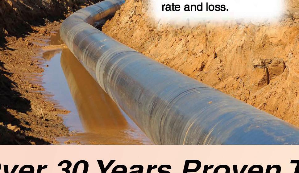


The demand for regular movement monitoring


The add-on cost of including an IMU within a traditional ILI campaign is nominal, however the overall cost of the inspection activity and


production interruptions mean that IMU tools are rarely used on a frequent basis unless the pipeline is highly susceptible to movement and alternative monitoring methods are flawed. Therefore, a dedicated solution was required that is costeffective and has minimal operational impact. ROSEN has recently developed a tool that incorporates IMU technology within the body of a cleaning tool which can be used as part of regular operational cleaning runs. The tool, RoGeo PD, can be run at higher speeds compared to conventional ILI tools, and so minimises the impact on pipeline throughput. The short tool length also simplifies tool handling as well as launching and receiving.

The tool has no odometer wheels to measure distance and instead uses the IMU to detect characteristic vibrations that occur as the tool passes over girth welds to enable alignment with a previous ILI. Initial inspection runs using this technology show that almost similar relative trajectory accuracy levels can be achieved compared to traditional IMU inspections, but the simplicity of the tool means that it can be run at a lower cost, thereby supporting the demand for a solution that can be run on a regular basis.
The value of ILI with IMU in integrity management of offshore pipeline
Undesired pipeline deformation and failures may occur from pipe bending resulting from insufficient engineering, installation mishaps and unintended environmental and operational loadings. As such, it is important that pipeline out-of-straightness is identified, measured and monitored from the day of installation/commissioning to the end of useful life so that the optimal and timely intervention actions may be taken by the pipeline operator. One method of achieving these goals involves the use of ILI with IMU as part of a wider integrity management plan. ILI with IMU has several benefits with regards to the integrity management of offshore pipelines.
Achievable benefits from a single IMU inspection run:
) Curvature measurements throughout pipeline. This will, if assessed together with external inspection data of freespans, for example, provide high quality input to ultimate strength checks and span modal analysis.
) Bending strain profile for full length of pipeline, providing insight into unintended forces acting on the pipeline.
) Detect global geometric anomalies such as lateral and upheaval buckles, or anchor drags.
) Combining IMU with Geometry and MFL or UT inspection technology – bending strains can be accurately correlated to other anomalies (e.g. corrosion, dents, gouges, wrinkles) within or in close proximity to the deviated shape. Data collected will support root cause analysis, allow for code compliance checks and detailed finite element modelling.
Achievable benefits from multiple IMU inspection runs include:

) Monitoring changes to the pipeline profile and bending strain levels.
) Early detection of upheaval buckles (not easily detectable by ROV for buried pipelines).
) Measuring the effect of thermal expansion on end terminations, tie-in spools and pipeline buckles.
) Monitoring pipe walking, ensuring that counter measures are installed in a timely manner.

) Early detection and monitoring of pipeline on bottom instability.
) Monitor for changes to span profiles and thereby optimise the need for costly external inspections.
Further developments in ILI technology and post-inspection processing have resulted in an effective solution to run IMU inspections on a regular basis at lower cost and lower operational impact. However, ILI with IMU will not provide a standalone integrity management solution, but is an invaluable and costefficient supplement to a wider management plan incorporating other inspection solutions, such as ROV/AUV.
Pedro Barbosa, Senior Product ManagerPipelines, Fotech, a bp Launchpad company, UK, explains why focusing on pipeline integrity is more important than ever, and how operators can use advanced technologies to improve pipeline safety.
ipeline integrity is a key concern for oil and gas operators wanting to ensure that pipelines are being operated in a safe and reliable way. Keeping pipelines free from defects and damage, so they can continue to transport their contents, without incident, is critical to preventing harmful substances from being released into the environment, and for protecting the population against potential incidents. Even the smallest oil and gas leaks can cause major environmental damage and the costs for clean-up can easily run into millions.
For example, the incident in Refugio Bay, off the west coast of the US, when, on 19 May 2015, 541 000 litres of crude oil spilled onto one of the most biologically diverse coastlines in the world. The cause of the leak was identified as being extensive corrosion, but unfortunately, it remained undetected until it was too late. Local pipeline workers did not know about

53
the leak until they were notified by the state parks staff that there was oil in the water. 1 Plains All American Pipeline L.P. and Plains Pipeline L.P. agreed to modify operations to prevent further spills, and to pay US$24 million in penalties, plus US$22.3 million in natural resource damages, US$10 million for natural resource damage assessment costs and US$4.26 million for Coast Guard clean-up costs. The overall cost of the clean-up, including expected legal claims and potential settlements, was approximately US$257 million. 2
So, what can operators do to prevent such incidents, and what are the best ways to ensure pipeline integrity and faster leak detection? There are a number of approaches to take that include considering the latest technologies, following the latest oil and gas pipeline standards and guidance, and establishing an integrity management (IM) plan.
Consider the latest advanced technologies
While it is common practice to install automatic leak detection systems in pipelines, there are several limitations with traditional systems, particularly internal based systems, due to their inability to detect small leaks and, when detected, to locate them accurately. This happens because there is no direct measurement of the leak phenomenon, but rather the leak is inferred from mass balance evaluations using parameters such as flow, pressure, temperature, etc.
However, distributed acoustic sensing (DAS) technology can monitor pipelines accurately for both leak detection and third-party interferences, including disturbances relating to attempted theft. DAS uses photonics, which essentially turns a fibre optic cable running alongside a pipeline network into thousands of vibration sensors, able to detect any disturbances along the length of the pipeline, even over hundreds of kilometres, and in realtime.
Delving into DAS
DAS technology, such as Fotech’s LivePIPE II solution, sends thousands of pulses of light along the fibre optic cable every second and monitors the fine pattern of light reflected back. When acoustic or vibrational energy –such as that created by a leak or by digging – creates a strain on the optical fibre, this changes the reflected light pattern. By using advanced algorithms and processing techniques, DAS analyses these changes to identify and categorise any disturbance. Each type of disturbance has its own signature, and the technology can tell an operator, in real-time, what happened, exactly where and when it happened.
IM can be improved through better data and having access to continuous, real-time information on the condition of the pipeline. Advanced technologies such as LivePIPE II give operators this continuous real-time data that enables them to make better informed decisions, so they can act more quickly in case of a pipeline incident or detected threat.
Looking at the latest legislation
The American Petroleum Institute (API), the benchmark for standards on operational and environmental safety, efficiency and sustainability, plays a vital role in promoting the performance standardisation of leak detection systems. Two key standards that provide pipeline operators with critical guidelines to support early and accurate leak detection, and which are essential for improving integrity and safety, are: API RP 1130 Computational Pipeline Monitoring for Liquids and API RP 1175 Pipeline Leak Detection-Program Management.
These standards were updated in April 2022 to now include external leak detection systems such as those based on fibre-optic sensing technologies. 3 Until now, these standards have solely focussed on internal-based leak detection systems, such as mass balance and real time transient modelling. But for the first-time, external systems such as DAS have been officially recognised as a practical and robust solution for leak detection – something many pipeline operators have known for some time.
The updated standards recognise the ability of external DAS systems to detect smaller leaks faster compared to traditional internal systems. The standards provide specific performance metrics that pipeline operators can follow. For example, RP1175 indicates targets and performance metrics that an operator might apply to a pipeline. While internal systems should detect leak sizes of +/-200 bbl/hr with a location accuracy of +/-5 miles (steady flow), external systems should detect leak sizes of +/-2 bbl/hr with a location accuracy of +/-10 m (steady flow).
Establish an integrity management plan
Another important step in improving integrity is to have a robust IM plan. In the US, the Pipeline and Hazardous Materials Safety Administration (PHMSA) provides regulations for pipeline operators to comply with to prevent pipeline leaks and corrosion. One of the requirements for operators of hazardous liquid, natural and other gas transmission and distribution pipelines is to develop and to implement comprehensive IM programmes. 4 These IM regulations are codified in Title 49 of the Code of Federal Regulations (CFR) Part 195, 195.452 for hazardous liquid pipelines, Part 192, Subpart O for gas transmission pipelines, and Part 192, Subpart P for gas distribution pipelines. 5
When prescriptive regulation is not in place, pipeline operators may choose to follow risk or performance-based approaches, recognised standards, RP’s and best practices, for example, API RP 1160 Pipeline Integrity Management Standard for Hazardous Liquid Pipelines and ASME B31.8S Managing System Integrity of Gas Pipelines.
IM plans are a documented and systematic approach to ensure the long-term integrity of pipelines. The process serves to assess and to mitigate risks in an effort to reduce both the likelihood and the consequences of incidents, and to optimise safety and performance.
Older concepts of integrity simply focussed on pipeline maintenance and inspection of the pipeline itself. This
54 World Pipelines / OCTOBER 2022


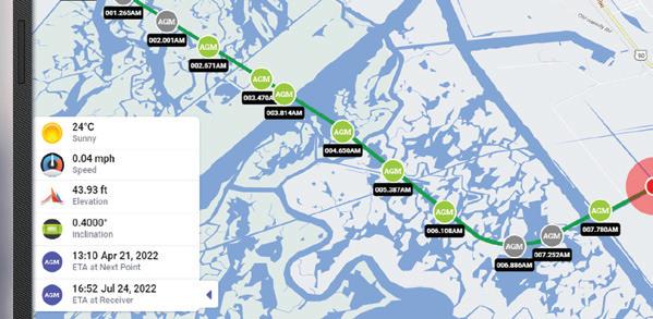


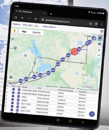


GlobalTracksm See more at GlobalTrack.info
considered primarily a pipeline’s physical qualities, support systems and the administration of an operator’s inspection programme. However, IM now takes a wider view, taking into account the environment as well. The regulations of hazardous liquid pipelines stipulate that oil and gas companies routinely assess pipelines in locations where a pipeline leak or failure could have significant adverse consequences, and where there is a higher risk of serious public or environmental safety.
Conclusion
Pipeline integrity is a critical topic for operators, and one that is continually evolving as oil and gas companies look to improve their practices and to operate to the highest safety levels. Over the past 40 years, IM has progressed from prescriptive visual inspection and assessment, to include risk-based IM using real-time data. 6
Not only can a well-managed pipeline integrity plan help operators identify and reduce safety risks before they escalate, but also play a major role in both achieving operational excellence and extending the life of ageing assets.
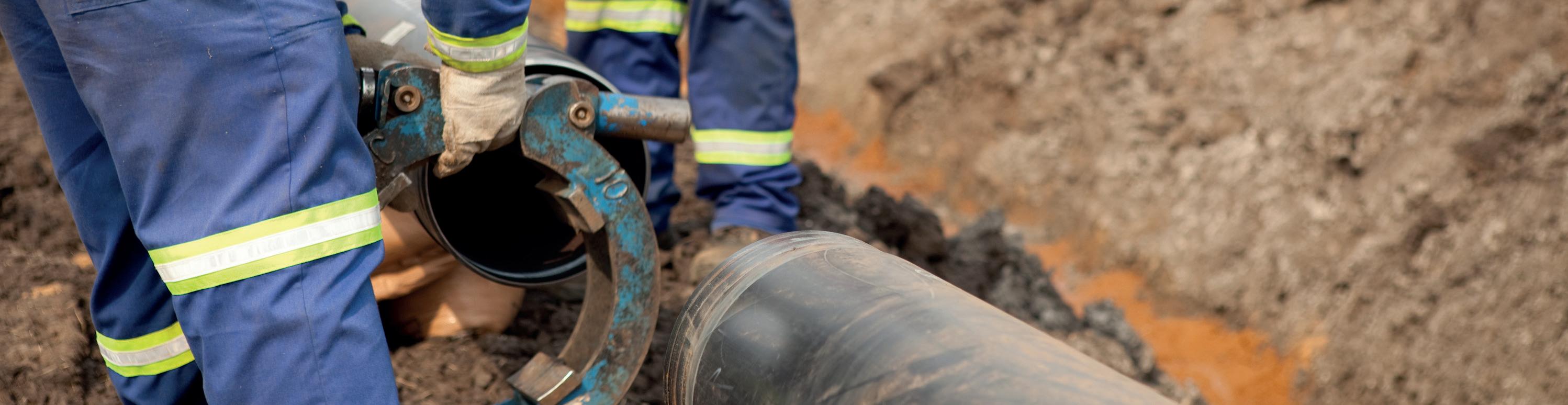
With pipeline integrity more important than ever, it is increasingly crucial that industry standards and legislation are applied. It is also essential that any regulations and standards are aligned with and reflect new technology advances. Only then can integrity ultimately be enhanced.
For example, the advantages of DAS are widely recognised by pipeline operators and it is already being used in leak detection applications and to improve pipeline integrity worldwide. The official acceptance by API and inclusion in its recommend practices validates the technology, giving operators 100% confidence in DAS’s accuracy and speed of detection so they can raise the safety and integrity levels of pipelines.
Worldwide Coverage ADVERTISERS’ DIRECTORY Advertiser Page ABC 43 CDI 55 CRC-Evans 4 Curtiss-Wright EST Group 2 Darby 37 DeFelsko 49 EDI 51 Fotech 27 Girard Industries 52 Intero 19 IPLOCA 28 LK2 21 LNG Industry IBC Maats b.v. 25 Midwestern 49 Pigs Unlimited International LLC 31 Pipeline Inspection Company 55 Propipe 45 Qapqa 41 ROSEN IFC SCAIP S.p.A. bound insert Stark Solutions 15 Stats Group 11 T.D. Williamson 7 Tracto Technik 45 Vacuworx OBC Winn & Coales International OFC, 46 Worldwide Machinery 35 Worldwide coverage www.worldpipelines.com/newsletter


Visit our website today: www.lngindustry.com LNG Industry Website The home for the latest LNG industry news, analysis and events
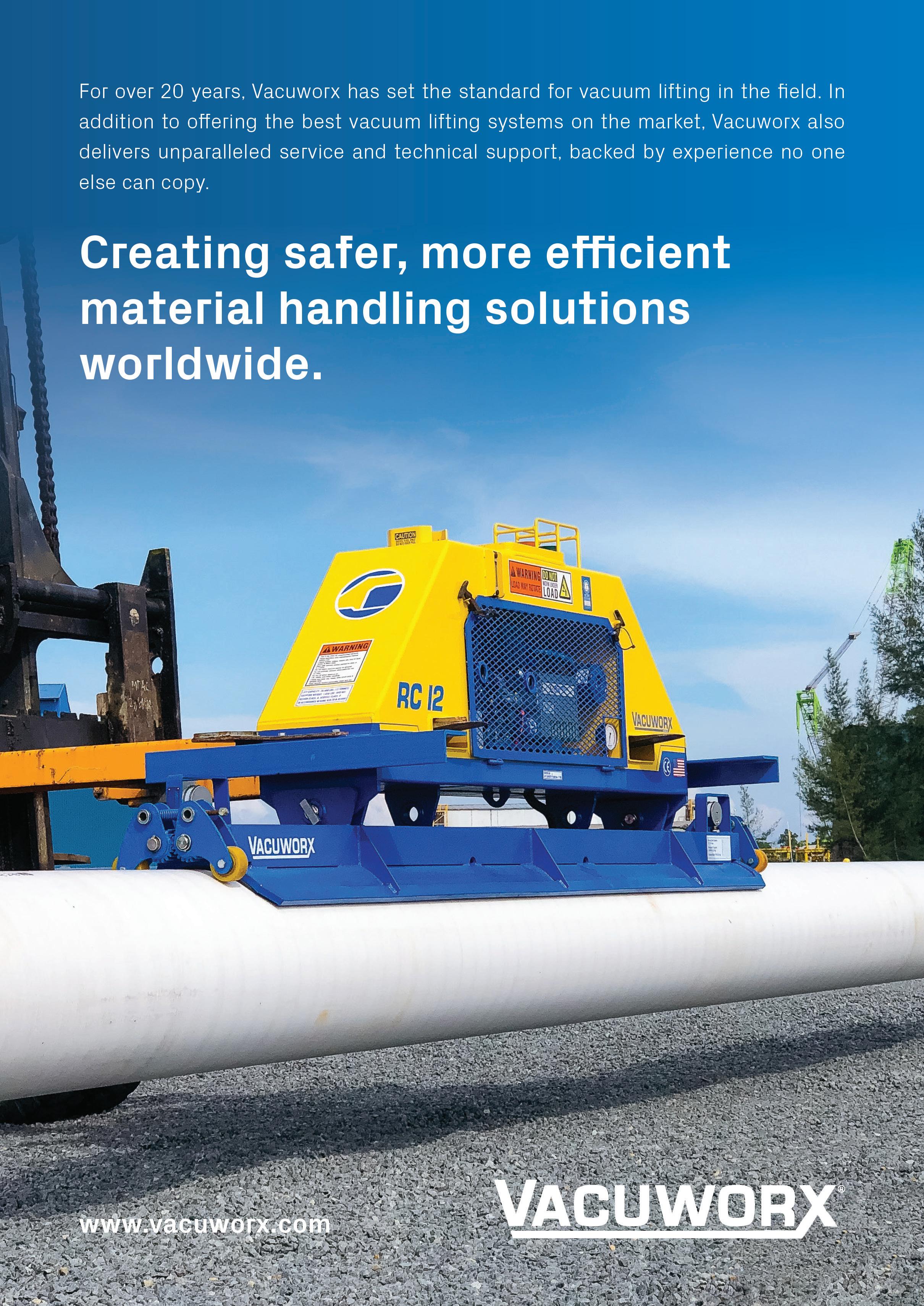

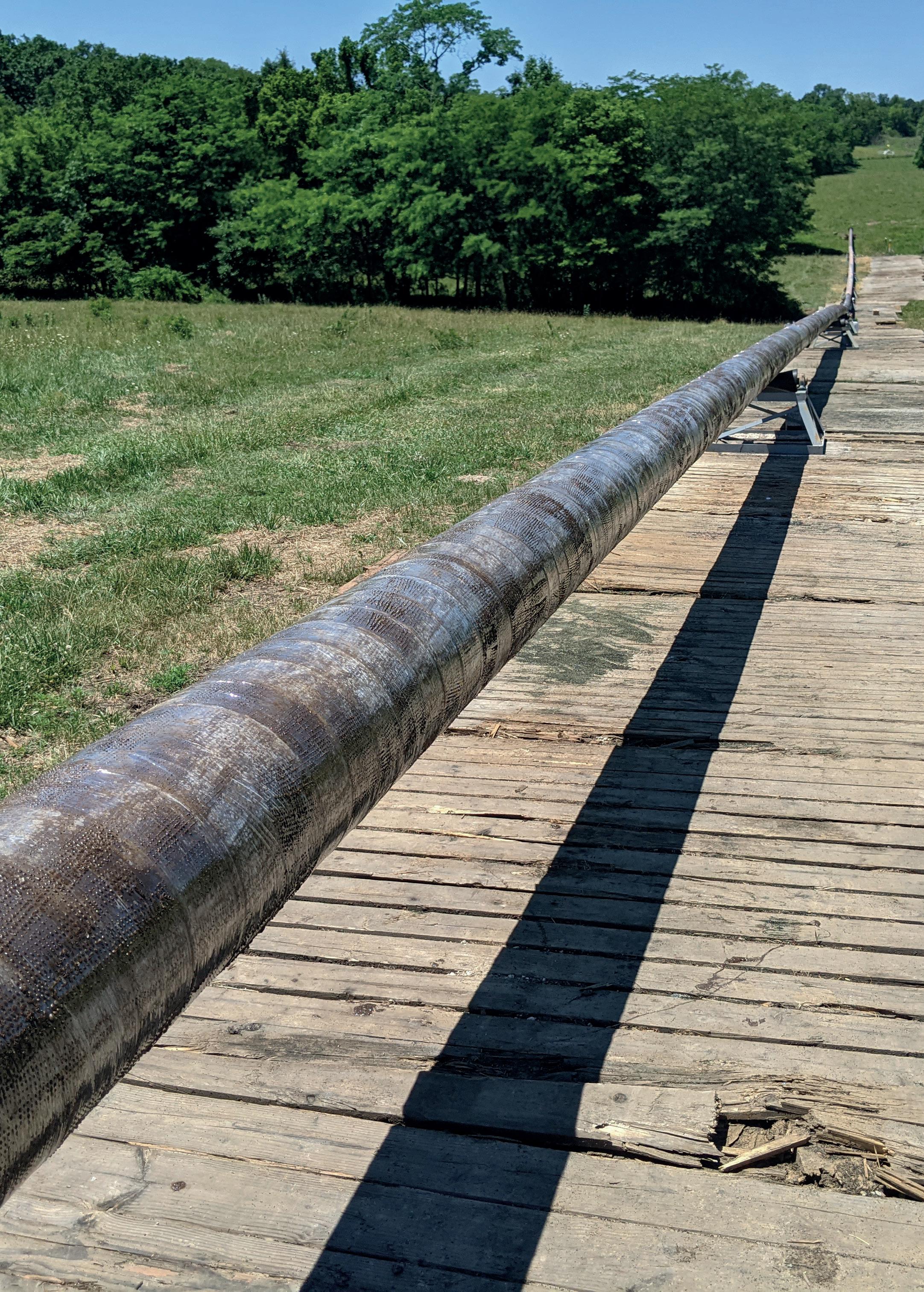


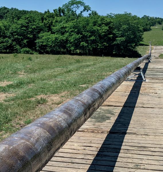


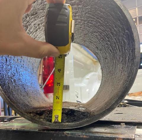


 Member of ABC Audit Bureau of Circulations