A conversation about the research, collaboration, and science behind safer, cleaner, and more efficient pipeline operations. Featuring Gary Choquette, Executive Director of Research at the Pipeline Research Council International (PRCI).
Gary shares his thoughts on:
• What PRCI does, and how it decides what to focus on.
• The Technology Development Centre in Houston – and why it’s a game changer.
• The industry’s readiness for hydrogen, CO2 and future fuels.
• Why collaborative research beats solo efforts every time.
• How PRCI supports transparency, safety and trust in the public eye
LISTEN NOW
CATCH UP ON RECENT EPISODES
Episode Eight: AMPP
Episode Seven: UKOPA
Episode Six: TDW
Gary
C O NTENTS
WORLD PIPELINES | VOLUME 25 | NUMBER 09 | SEPTEMBER 2025
03. Editor's comment
05. Pipeline news
Pipeline news from the UK, USA,Germany, Ireland, and Singapore.
KEYNOTE: ENVIRONMENT AND EMISSIONS
10. Seeing the unseen Paul Stockwell, Managing Director, Process Vision, elaborates on
OFFSHORE PIPELINES
20. Bridging performance gaps in extreme environments Henk de Boer and Fabienne Ellington, Strohm, the Netherlands.
27. Enhancing marine safety, competence and innovation
Roger Moore and Sara McQuillan, International Marine Contractors Association (IMCA).
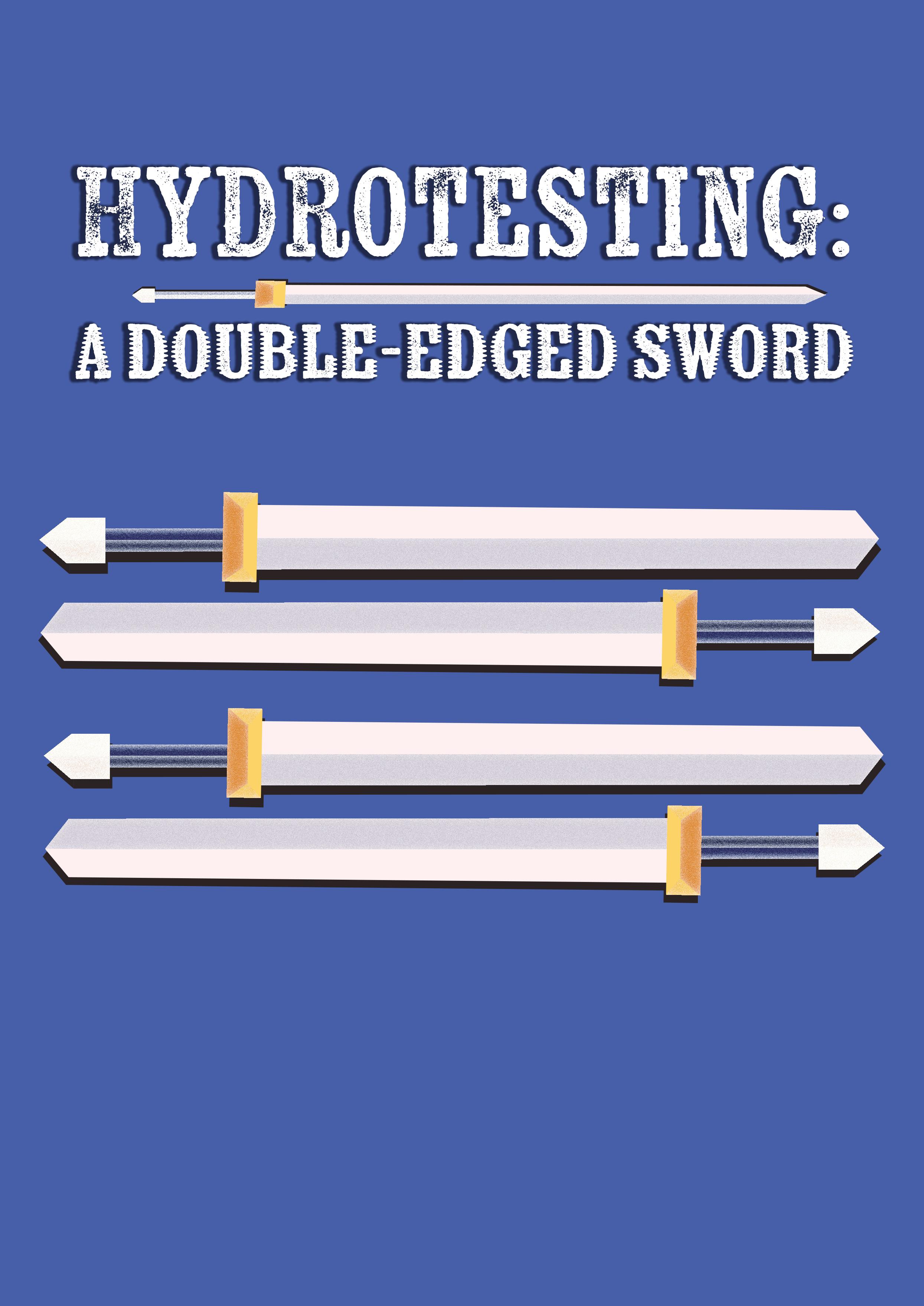
31. Hydrotesting: a double edged sword
Julie Holmquist, Cortec Corp.
SYSTEMS AND SOFTWARE
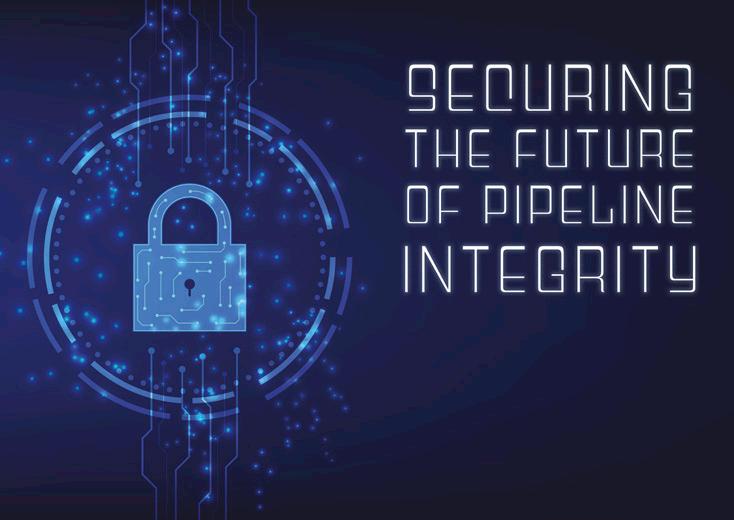
36. Securing the future of pipeline integrity
David Niehueser and Simon Braun, ROSEN Group.
HYDROGEN PIPELINES
41. 360° inspection
Brendan Shanahan, Dexon Technology, Thailand.
INTEGRITY AND INSPECTION
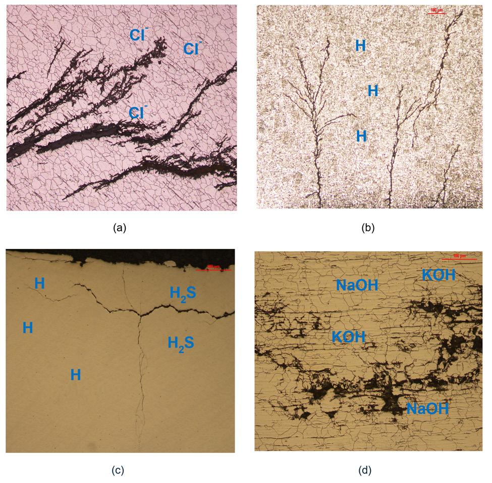
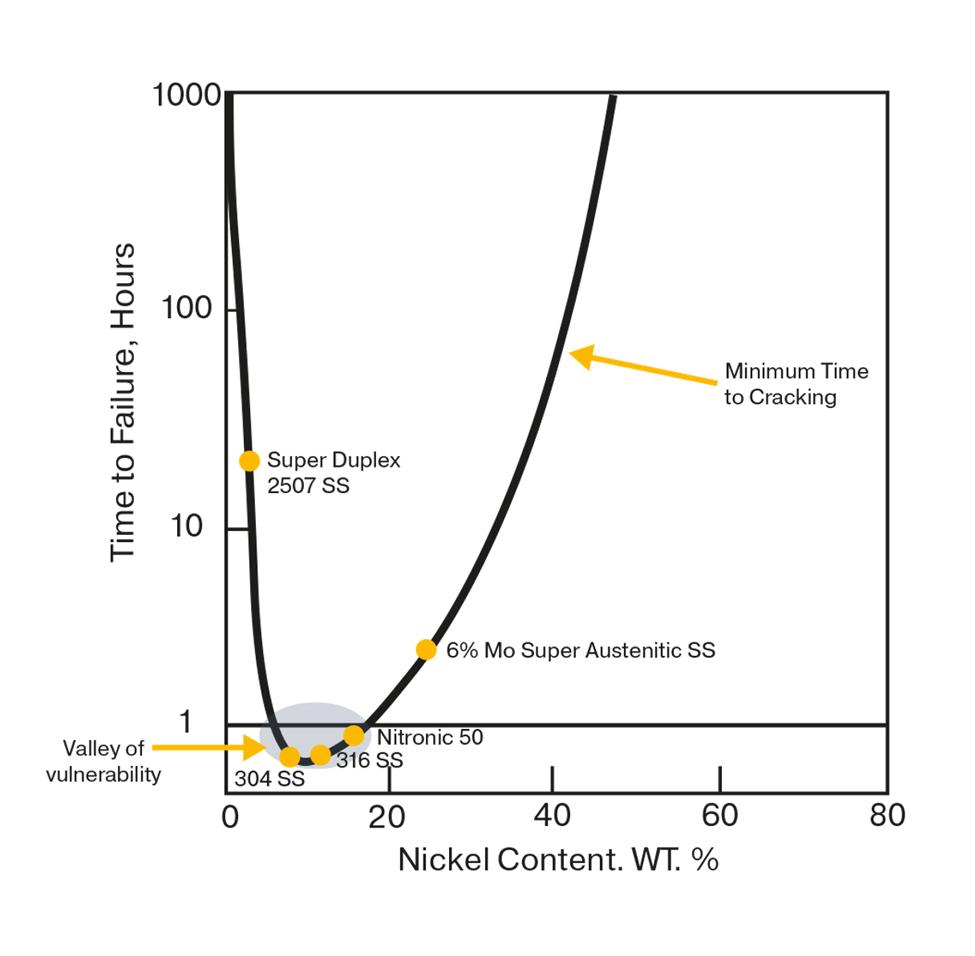
47. Understanding and mitigating stress corrosion cracking Anshul Godha and Paula LePore, Parker Hannifin.
NORTH AMERICA FOCUS
53. A strategic choice
Tim Hill, Commercial General Manager, Nucor.
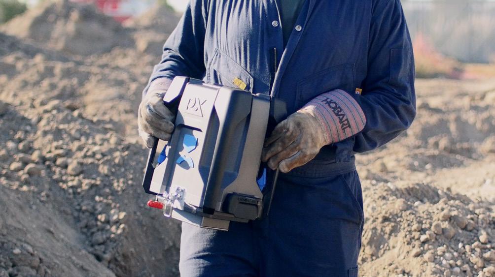
57. The consequences of inaccurate material verification data James Dean, CEO, Plastometrex.
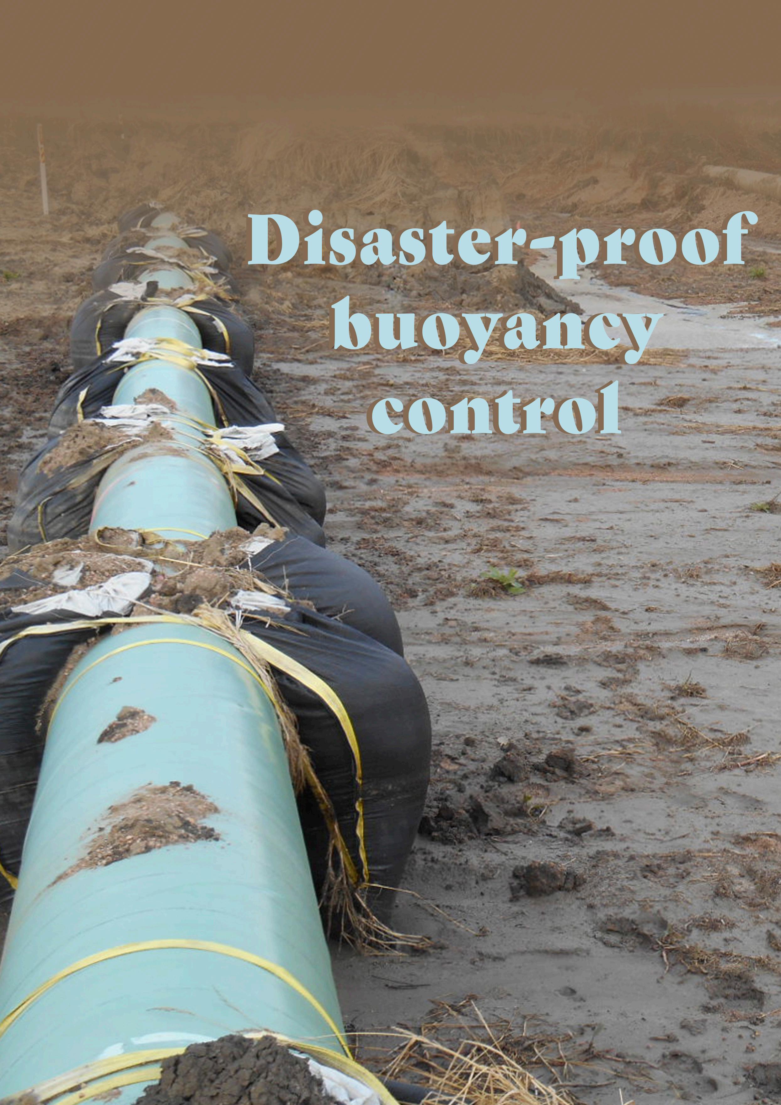
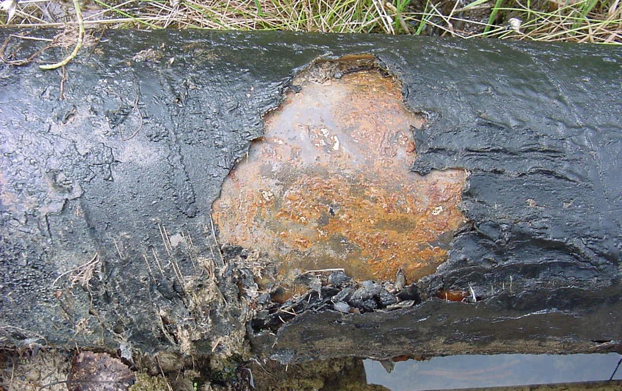
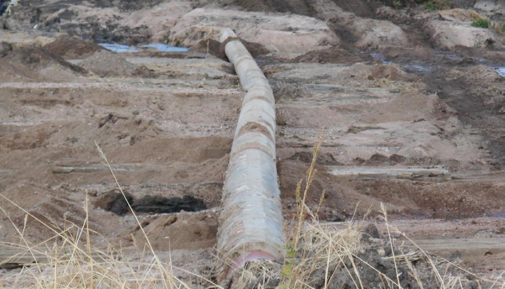
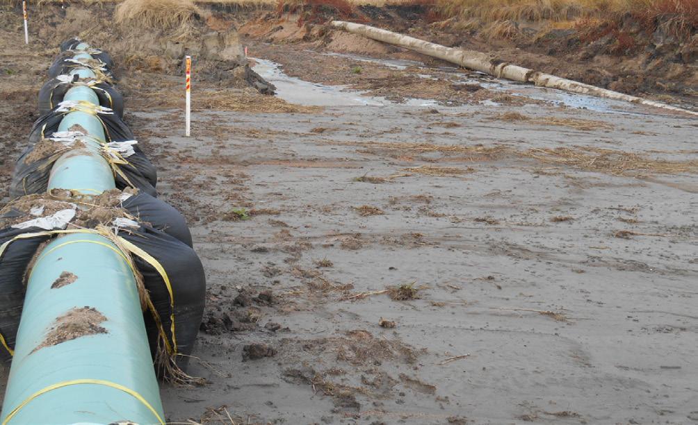
61. Disaster-proof buoyancy control Meghan Connors, President, PipeSak Incorporated, Canada.
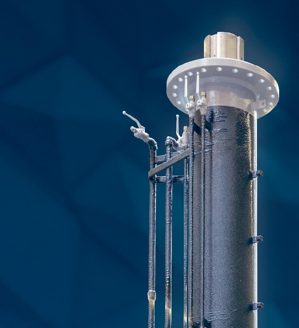
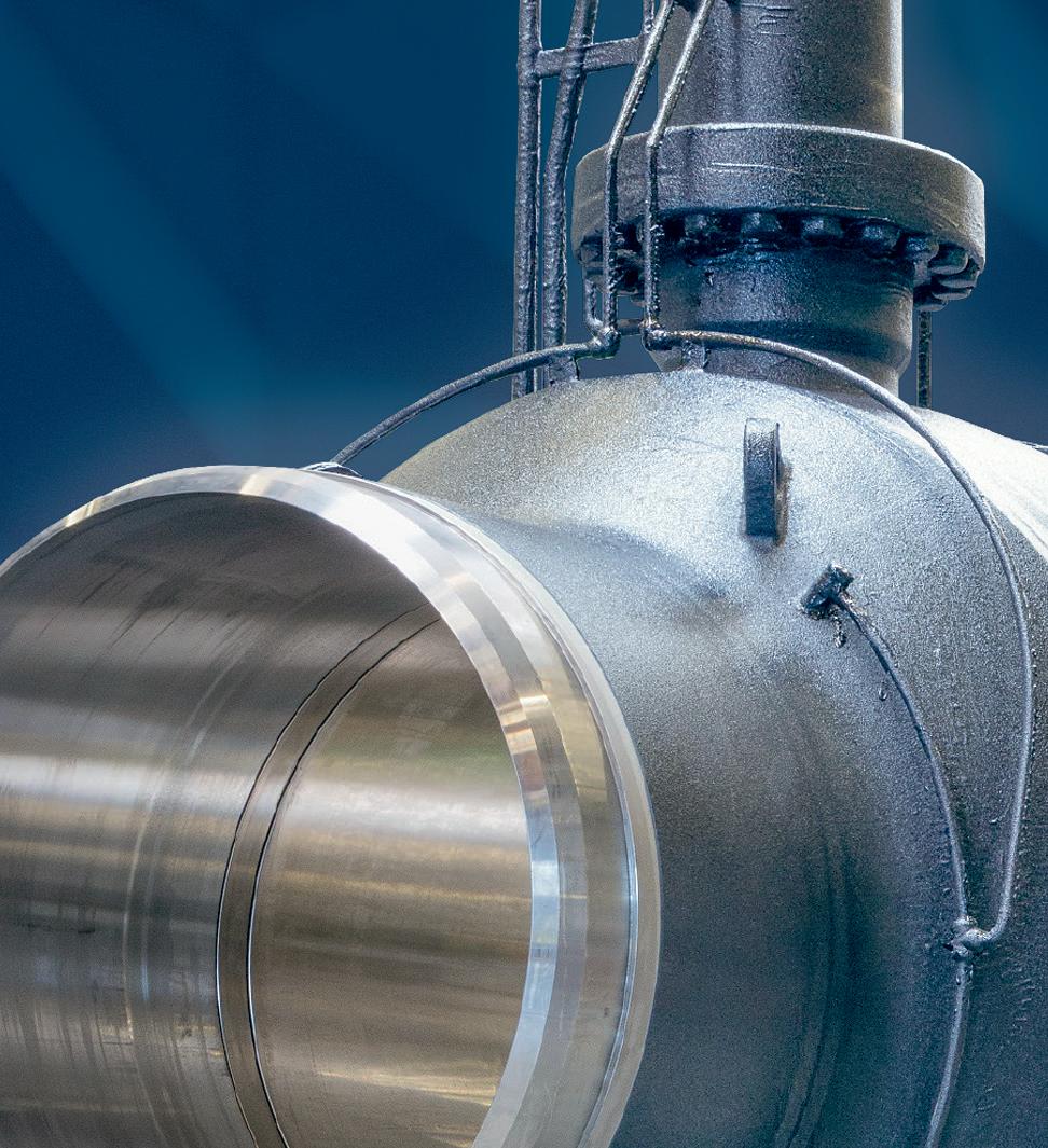
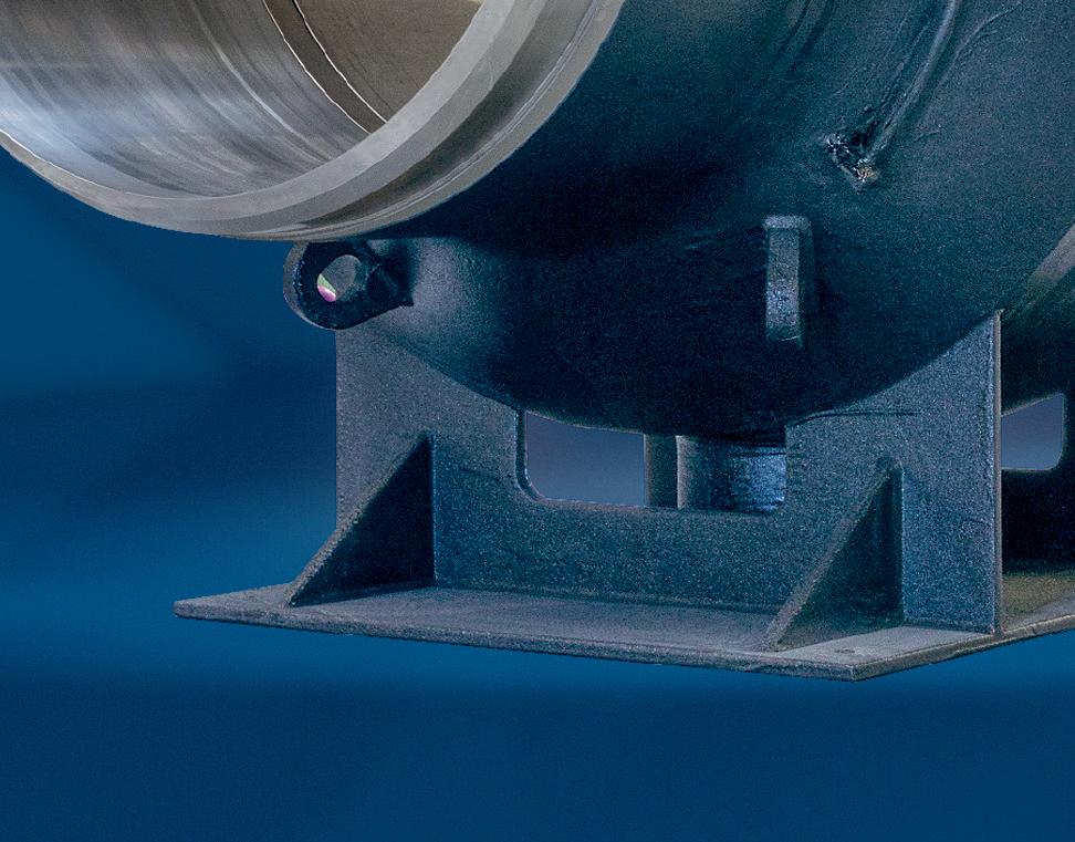
THIS MONTH'S COVER Reader enquiries [www.worldpipelines.com]
Engineered for extreme conditions, Powercrete DD410 offers a new generation solvent-free epoxy ARO coating that provides high performance protection to pipelines for directional drilling, thrust bore, and pull through applications. This product has exceptional abrasion, strength, hardness, impact resistance, and adhesion properties, a pioneering technology ready to tackle the most demanding of applications. Find out more at www.powercrete.com
EDITOR’S COMMENT
CONTACT INFORMATION
MANAGING EDITOR
James Little james.little@worldpipelines.com
EDITORIAL ASSISTANT
Emilie Grant emilie.grant@worldpipelines.com
SALES DIRECTOR
Rod Hardy rod.hardy@worldpipelines.com
SALES MANAGER
Chris Lethbridge chris.lethbridge@worldpipelines.com
Annual subscription £60 UK including postage/£75 overseas (postage airmail). Special two year discounted rate: £96 UK including postage/£120 overseas (postage airmail). Claims for non receipt of issues must be made within three months of publication of the issue or they will not be honoured without charge. Applicable only to USA & Canada: World Pipelines (ISSN No: 1472-7390, USPS No: 020-988) is published monthly by Palladian Publications Ltd, GBR and distributed in the USA by Asendia USA, 701C Ashland Avenue, Folcroft, PA 19032. Periodicals postage paid at Philadelphia, PA & additional mailing offices. POSTMASTER: send address changes to World Pipelines, 701C Ashland Avenue, Folcroft, PA 19032.
SENIOR EDITOR Elizabeth Corner elizabeth.corner@worldpipelines.com
As the end of summer approaches in the Western Hemisphere, attention inevitably turns to the preparedness of energy systems for the colder months ahead. Gas storage levels become a focal point, as they hold the key to ensuring a stable supply throughout the winter. This time of year serves as a reminder for energy stakeholders to assess the resilience of their infrastructure, and strategies, for meeting winter energy needs. The ability to maintain strong gas storage levels is crucial for avoiding disruptions and for navigating the kind of geopolitical, weather, and energy consumption factors that can affect each region’s resilience in the winter months.
The EIA reported in August that US natural gas storage levels remain above average as the sector moves through injection season. In the latest Short-Term Energy Outlook, the EIA forecasts that US working natural gas inventories will reach 3872 billion ft3 by the end of October, or 2% more than the previous five year average for that time of year.1 Natural gas inventories grew quickly in late April to early June, with seven consecutive weeks of net injections to inventories exceeding 100 billion ft3 each for the first time since 2014. This gives the US a buffer heading into the winter months. The US relies heavily on natural gas due to its abundant domestic supply, low costs, and extensive infrastructure, ensuring energy security and supporting export potential.
As the US shows resilience in gas production and storage, Europe is navigating a vastly different energy landscape. In September, the global energy community will convene in Europe (in Milan) for Gastech, to discuss the future of natural gas, LNG, alternative fuels, and climate technologies. As Europe strides towards its ambitious 2027 deadline to eliminate reliance on Russian gas, the event will serve as a critical juncture for discussing Europe’s energy resilience and the role of gas in the transition to a low-carbon energy future. The EU’s strategy to phase out Russian energy imports necessitates a robust diversification of supply sources and a re-evaluation of energy infrastructure.
The EU’s ongoing efforts to wean itself off Russian gas are shifting the region’s energy reliance towards diversified LNG sources and renewable options. European gas storage levels are projected to hit 79% by the end of August, providing a solid cushion ahead of the colder months. However, this figure is a full 14% lower than the previous year, underscoring the challenges that remain as European gas imports are increasingly decoupled from Russian pipelines.
The recently-published ICIS Gas and Power Foresight report illustrates a fragile but essential strategy: Europe’s increasing reliance on LNG send-out (up 58% from the previous year) highlights the ongoing diversification of supply.2 But the looming risks of low wind and nuclear outages across the UK and Central Western Europe demonstrate how easily the region could face volatility, especially during harsh winter months.
The potential for global LNG shortages is real, especially as demand from China intensifies, and the high price volatility associated with LNG trading continues to exert pressure on markets. The global market’s tight supply-demand balance reinforces the case for strategic gas storage as an essential element in stabilising prices and guaranteeing security of supply. For Europe, achieving its storage goals is critical to managing the risks that come with LNG reliance.
At Gastech, discussions will focus on emerging technologies like hydrogen and AI, but also on the critical role of gas pipeline infrastructure in Europe’s energy future. The resilience and flexibility of pipeline networks will be key to ensuring energy security and supporting the transition to diverse, low-carbon energy sources.
Across energy and critical infrastructure, we bring expertise where complexity is highest, partnering with globally local teams and leveraging unrivalled proprietary technologies. Like the M-500 Single Torch External Welding System, seamlessly integrated with Data 360 our cloud-based digital platform that analyses, and visualises your project performance data in real time. We move projects forward, no matter the challenge.
We’re here to partner on how our specialist welding and coating solutions can help you power tomorrow.
WORLD NEWS
Peru’s Petroperu considers pipeline link for Ecuador oil
State-run Petroperu is working on a framework agreement with its counterpart Petroecuador to connect oil wells in Ecuador with Peru’s northern pipeline, its Chairman said (according to Reuters).
The agreement, which is being drafted by Peru’s Ministry of Energy and Mines, would include investment and execution commitments for an approximately 60 km (37 mile) connection line in an Amazonian region on the countries’ shared border.
“The exact investment for this connection and how it will be financed have yet to be defined,” Petroperu Chairman Alejandro Narvaez said.
Speaking at a conference with the foreign press, the executive stated that the project, after a development period, would allow Ecuadorean crude to reach the newly expanded
95 000 bpd Talara refinery in northern Peru via the pipeline.
The Peruvian oil company, which is navigating a crisis after the larger-than-planned investment in Talara, expects to post a profit of US$103 million next year, recovering from an estimated loss of US$223 million for 2025.
Petroperu CEO Oscar Vera, speaking at the same conference, said Petroecuador would likely make the majority of the investment. “It is of greater interest to them, because it is very costly for Petroecuador to transport crude using their current methods,” Vera said.
Peru’s 1100 km pipeline, which has suffered frequent attacks from local communities that have halted its activities, is currently operational but is not in service as it has no active transport contracts with area producers.
Saipem completes pipeline installation for Equinor’s Irpa project in the Norwegian Sea
Saipem has completed the installation of the subsea pipeline for the Irpa project, developed by Equinor in the Norwegian Sea. Offshore operations were carried out by the pipelay vessel Castorone, one of Saipem’s flagship vessels.
The project encompassed the installation of a pipe-in-pipe pipeline of approximately 80 km at a depth of 1350 m, making Irpa the deepest subsea field development in Norway to date. The pipeline will connect Irpa’s underwater production system to the Aasta Hansteen platform.
Pipe-in-pipe technology represents an advanced and highly reliable solution for transporting hydrocarbons in extreme environmental conditions and consists of a dual-
pipe system, in which an internal pipeline transports the fluid while an external one protects it. This design maintains the fluid’s temperature along its path on the seabed, preventing the risk of obstruction caused by the formation of hydrates or waxes, phenomena that are particularly critical in cold, deep waters like those of the Norwegian Sea.
Installation activities of the 20 in. diameter pipeline were completed on 22 July, after 84 days of uninterrupted operations. Complex logistics supported operations from the Norwegian port of Sandnessjøen, where the prefabricated joints and equipment were loaded, onto support vessels and transferred to the Castorone
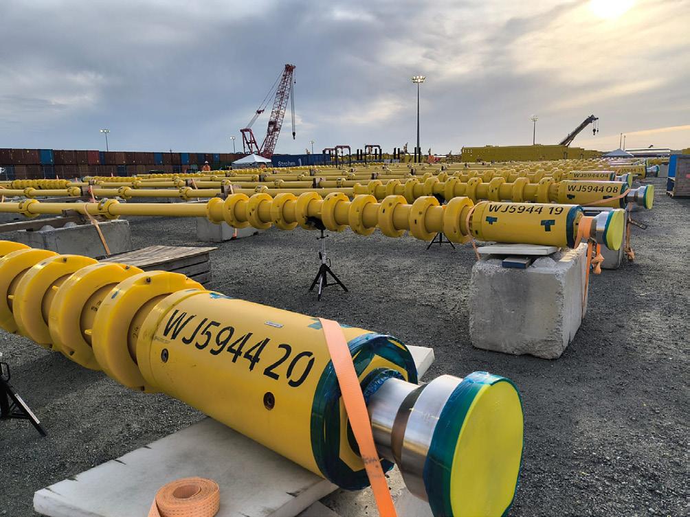
Strohm completes the first 13 jumpers for ExxonMobil in Guyana
In a first for both the region and the client, Strohm has completed fabrication of the first 13 water alternating gas injection (WAG) thermoplastic composite pipe (TCP) Jumpers as part of its innovative Jumper on Demand concept, for ExxonMobil’s Yellowtail field offshore Guyana.
Strohm’s Jumper on Demand concept allows multiple pipe lengths to be spooled from a delivery reel of continuous pipe and cut into discrete jumper lengths onsite. The individual jumpers are then fabricated in parallel by the company’s Field
Service Group, a team of specialists which are trained in pipe handling and termination of TCP.
This approach provides a safe, efficient and flexible method to produce large volumes of jumpers faster.
The first two TCP Jumpers were successfully integrated with vertical connections, pressure tested and installed subsea at depths of more than 1700 m earlier this month. The jumpers, installed by spreader bar, were locked in and back seal tested successfully by the client’s installation contractor.
Corinth Pipeworks awarded supply contract for Greece–North Macedonia Natural Gas Interconnector
Corinth Pipeworks has announced its participation in the Greece–North Macedonia Natural Gas Interconnector. The project, jointly developed by DESFA (Greece) and NOMAGAS (North Macedonia), entails the construction of a 123 km pipeline, 55 km in Greece (previously awarded to Corinth Pipeworks) and 68 km in North Macedonia, linking the national natural gas transmission systems of the two countries. This strategic interconnection will enable North Macedonia to diversify its energy sources, reducing dependency on a single supplier, while securing access to Greece’s advanced natural gas transmission network and LNG infrastructure.
Following the successful execution of the Greek section, Corinth Pipeworks has now also been awarded the supply of
28 in. Helical Submerged Arc Welded (HSAW) linepipe for the North Macedonian section of the pipeline by RAPID BILD DOO. All pipes are certified for hydrogen transportation in accordance with ASME B31.12 – Option B, ensuring future readiness for clean energy integration.
“We are shaping the future of hydrogen infrastructure,” said Ilias Bekiros General Manager, Corinth Pipeworks. “This project represents not only an important cross-border collaboration but also a strong step toward decarbonisation and energy resilience in Southeast Europe.”
The Greece–North Macedonia Interconnector is expected to be operational in the 1H27.
WORLD NEWS
IN BRIEF
Canada
Pembina has entered into a long-term tolling agreement with AltaGas for 30 000 bpd of LPG export capacity at AltaGas’ current Ridley Island Propane Export Terminal (RIPET) and future Ridley Island Energy Export Facility (REEF).
Germany
Rolls-Royce’s Power Systems division, with its mtu product and solutions brand, continued its rapid profitable growth in the first half of 2025.
USA
SFPP, LP, a subsidiary of Kinder Morgan, Inc., has announced the launch of a binding open season to solicit commitments to support a proposed expansion of the East Line portion of its pipeline system from El Paso, Texas to Tucson, Arizona.
Ireland
NDT Global has announced the acquisition of Entegra, a technology company specialising in Ultra-HighResolution Magnetic Flux Leakage (UHR MFL) inline inspection services.
Singapore
The National University of Singapore’s Energy Studies Institute and FutureScaleX have released a new policy brief on US climate policy reversal and Asia’s growing CCS opportunity.
USA
MPLX LP has announced it has entered into a definitive agreement to acquire Northwind Delaware Holdings LLC (Northwind Midstream) for US$2.375 billion in cash consideration, subject to customary purchase price adjustments.
Baker Hughes to acquire Chart Industries
Baker Hughes and Chart Industries have announced that they have entered into a definitive agreement under which Baker Hughes will acquire all outstanding shares of Chart’s common stock for US$210 per share in cash, equivalent to a total enterprise value of US$13.6 billion.
“This acquisition is a milestone for Baker Hughes and a testament to our strong financial execution and strategic focus as we continue to define our position as a leading energy and industrial technology company,” said Baker Hughes Chairman and CEO Lorenzo Simonelli. “We know Chart well, having
worked alongside them on many critical energy infrastructure projects. Their products and services are highly complementary to our offerings and strongly aligned with our intent to deliver distinctive and efficient end-to-end lifecycle solutions for our customers across their most critical applications.
'The combination positions Baker Hughes to be a technology leader that can provide engineering and technology expertise to meet the growing demand for lower-carbon, efficient energy and industrial solutions across attractive growth markets such as LNG, data centres and New Energy.”
Energy Transfer announces expansion of Permian Basin natural gas pipeline
Energy Transfer LP has announced it has reached a positive financial investment decision (FID) for the expansion of its Transwestern Pipeline to increase the supply of natural gas to markets throughout Arizona and New Mexico from Energy Transfer’s premier asset base in the prolific Permian Basin.
Transwestern’s Desert Southwest pipeline expansion will provide reliable economic supplies of natural gas to support the long-term energy needs for utilities and energy providers in the region driven by population growth, high-tech industry demand and data cent expansion.
The Desert Southwest pipeline expansion project consists of 516 miles of 42 in. pipeline and nine compressor stations in Arizona, New Mexico and Texas. The design capacity of
the pipeline is 1.5 billion ft3/d). The strategic system expansion extends Transwestern’s natural gas pipeline network, enhancing system reliability and providing additional optionality serving rapidly growing demand in the Southwestern US region. The project is expected to be in-service by 4Q29.
The project is expected to cost approximately US$5.3 billion including US$0.6 billion of Allowance for Funds Used During Construction (AFUDC), and is supported by significant long-term commitments from investment-grade customers.
Depending on the final results of the open season, the project could be efficiently expanded to accommodate additional demand.
Ditch Witch completes sale of Trencor business
and American Augers auger boring line
Ditch Witch, a division of The Toro Co., has announced several strategic actions to support future growth in its core segments, drive operational efficiencies and reinforce its position as the authority in the underground construction industry.
Focused on delivering solutions that align with the evolution of our targeted industries, The Toro Co. has completed the sale of the Trencor business and the auger boring product line of the American Augers business. These actions allow Ditch Witch and American Augers to strengthen its focus on HDD, a rapidly growing segment of the underground
construction market supported by demand in the pipeline, water and energy transmission sectors.
Under the Ditch Witch Division, American Augers will continue to design, manufacture and distribute its line of horizontal directional drills, pumps and fluid cleaning systems for complex infrastructure projects. As underground construction projects become more challenging, Ditch Witch’s renewed focus on HDD and trenchless technologies underscores its commitment to operational excellence, innovation and meeting the evolving needs of contractors worldwide.
PROTECTIVE OUTERWRAPS
BUTYL TAPE WRAP SYSTEMS
LIQUID EPOXY COATINGS
PETROLATUM TAPE WRAP SYSTEMS
SOIL-TO-AIR INTERFACE
HEAT SHRINKABLE SLEEVES
INTERNAL PIPE LININGS
BITUMEN TAPE WRAP SYSTEMS
9 - 12 September 2025
CONTRACT NEWS
Boskalis
- Allseas consortium wins offshore gas pipe project in Taiwan
Boskalis and Allseas have announced that their 50/50 consortium has been awarded a large contract by CPC Corporation Taiwan for the second offshore gas pipeline from Yongan to Tongxiao (YT2). The total contract value is approximately €1.2 billion. This landmark energy project is intended to support the acceleration of energy transition in Taiwan and improve the gas supply capacity in northern Taiwan.
Under the contract, the consortium will design, construct, install and pre-commission the new YT2 36 in. offshore natural gas pipeline, which will run approximately 232 km parallel to the existing YT1 pipeline, connecting the Yongan LNG terminal in the Southwest with the Tongxiao transfer station in the Northwest. The comprehensive scope of work includes trenching, pipeline installation with 34 crossings over existing
Valmet signs broad Brazil valve deal with Petrobras
Valmet has signed a nationwide agreement with Petrobras (Petróleo Brasileiro S.A.), the largest energy company in Brazil. The agreement covers the supply of spare parts of Neles™ valves, actuators, and positioners across all Petrobras operational units, including oil and natural gas exploration, production, refining, commercialisation, and power generation.
The first order was included in Valmet’s orders received in 2Q25. Potential resulting orders will be recognised over the agreement period. The value of the orders will not be disclosed.
With an initial term of one year and the possibility of automatic renewal for up to five years, the agreement is a significant milestone in the partnership between the two companies. The initiative offers Petrobras strategic benefits such as guaranteed valve equipment availability, greater cost predictability, streamlined processes, reduced bureaucracy, and specialised technical support with a recognised quality standard.
With this agreement, Valmet reaffirms its commitment to customer service excellence, directly contributing to the efficiency and operational continuity of Petrobras’s plants
and future infrastructure and assets, backfilling and two landfalls.
Within the consortium, Boskalis will be responsible for the landfalls and associated micro-tunnelling activities, as well as nearshore and offshore trenching, backfilling, and the installation of rocks for the 34 pipeline crossings. For these activities, Boskalis will deploy two large hopper dredgers, a large backhoe dredger, and a subsea rock installation vessel.
Allseas will carry out the pipeline installation and pre-commissioning, including the pre-lay installation of concrete mattresses. For these activities, Allseas will deploy two of the most advanced pipelay vessels in the industry.
Project execution is scheduled to commence in 2026, with completion anticipated in 2028.
ON OUR WEBSITE
• Duke Energy announces sale of its Tennessee Piedmont Natural Gas business to Spire for US$2.48 billion
• Baker Hughes to supply dragreducing agents to Genesis Energy, increasing offshore pipeline capacity
• McDermott awarded offshore contract by Brazil’s BRAVA Energia
• Bridger Photonics announces methane leak detection contract with Pacific Gas & Electric
Follow us on LinkedIn to read more about the articles linkedin.com/showcase/worldpipelines
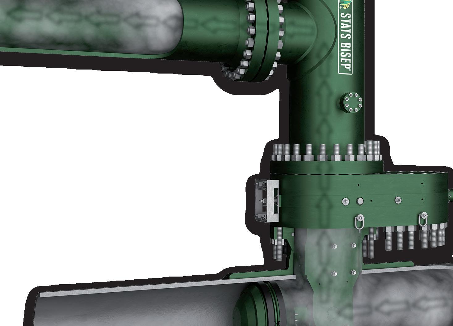
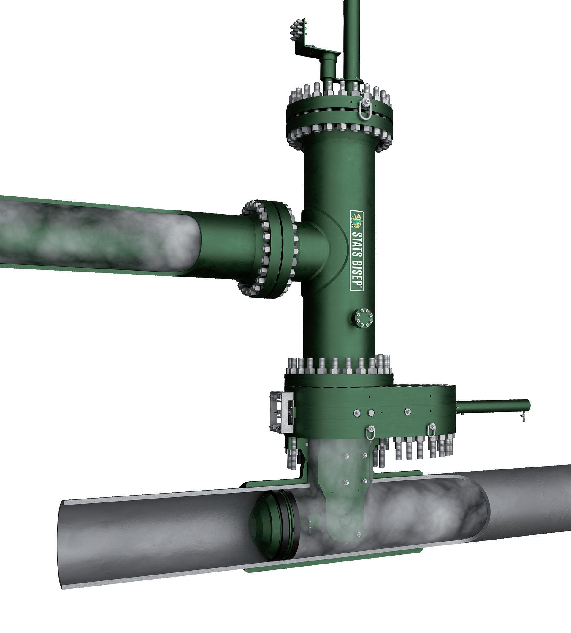
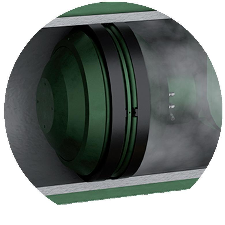
integrated bypass maintains production during isolation
Dual Leak-Tight Seals
Double Block & Bleed Isolation
Isolated Pipeline
Monitored Zero-Energy Zone
The BISEP® has an ex tensive track record and provides pioneering double block and bleed isolation while
dual seals provide tested, proven and fully monitored leak-tight isolation, ever y time, any pressure.
Paul Stockwell, Managing Director, Process Vision, elaborates on how operators can prevent emissions from compressor incidents by using real time visual monitoring.
Natural gas transmission infrastructure, specifically compressor stations and pipelines, remains a significant and ongoing source of methane emissions into the atmosphere. According to the US Environmental Protection Agency (EPA), compressor stations within the ‘Transmission and Storage’ segment are among the largest point sources of fugitive methane emissions in the natural gas industry, from equipment leaks, blowdowns, and seals. 1 Further, the EPA reports that this segment accounts for roughly 19% of total methane emissions from oil and gas operations in the US, with a substantial portion attributable to compressors. 2 These emissions arise primarily from venting of pressurised gas, leaky components, and compressor-related venting, all consistent with unplanned incident scenarios that release methane directly into the atmosphere.
Compressor start-ups and emission risks
While emissions from routine operations are expected and accounted for in design, it is the unplanned or unexpected events that lead to significant environmental damage. The three high-risk events are:
) The start-up of compressors after a period of zero flow but the pipeline has remained at pressure.
) Pigging operations where some portion of the liquids and material gathered during pigging bypass
the slug catcher and move forward to downstream compressors.
) A upstream process failure e.g., a hole in a gas/liquid heat exchanger allows high levels of liquid into the gas stream.
When contaminants such as natural gas liquids (NGLs), compressor oils, or glycols enter the compressor inlet during restarts, they can compromise seals, trip safety systems, or cause catastrophic failures. While knock-out drums at the compressor inlet are designed to protect the compressor, liquid slugs at start-ups and during pigging can be at higher volumes than the knock-out drum is designed for. These incidents often result in blowdown venting or flaring, releasing not only methane but also volatile organic compounds. 3
Limitations of hydrocarbon dewpoint measurement
One of the biggest changes to the industry has happened now that activity within a live gas pipeline can be observed. Seeing is believing – on frequent occasions liquid NGLs are observed in either mist flow, stratified flow (or both) while the reported hydrocarbon dewpoint for the gas stream indicates that the gas would need to be cooled by over 127°F (70°C) before liquids started to condense. It is clear that traditional gas quality assurance methods are not equipped to manage the challenge of determining if a gas is dry. Hydrocarbon dewpoint, while still a contractual standard, is commonly an inferred measurement based on gas composition and calculated thermodynamic properties. Moreover, sampling methods outlined in API 14.1 and ISO 10715 deliberately avoid two phase flow, meaning mists or stratified liquids are inherently excluded from analysis. When even small amounts of liquid carryover are present, key gas components (hydrogen sulfide [H 2S], carbon dioxide [CO 2], and C1 - C6 hydrocarbons) dissolve into the liquid phase according to Henry’s Law. This causes under-reporting in gas-phase analysis, leading to inaccurate BTU, H 2S, and CO 2 readings. All of which mean that without visual validation of the presence of liquids, it is not possible to determine if a liquid phase is present by monitoring gas phase only. With no liquids present, gas analytics and flow meters are accurate. If liquids appear, expect significant loss of accuracy on flow measurement and measurement of gas phase components.
Real-time monitoring
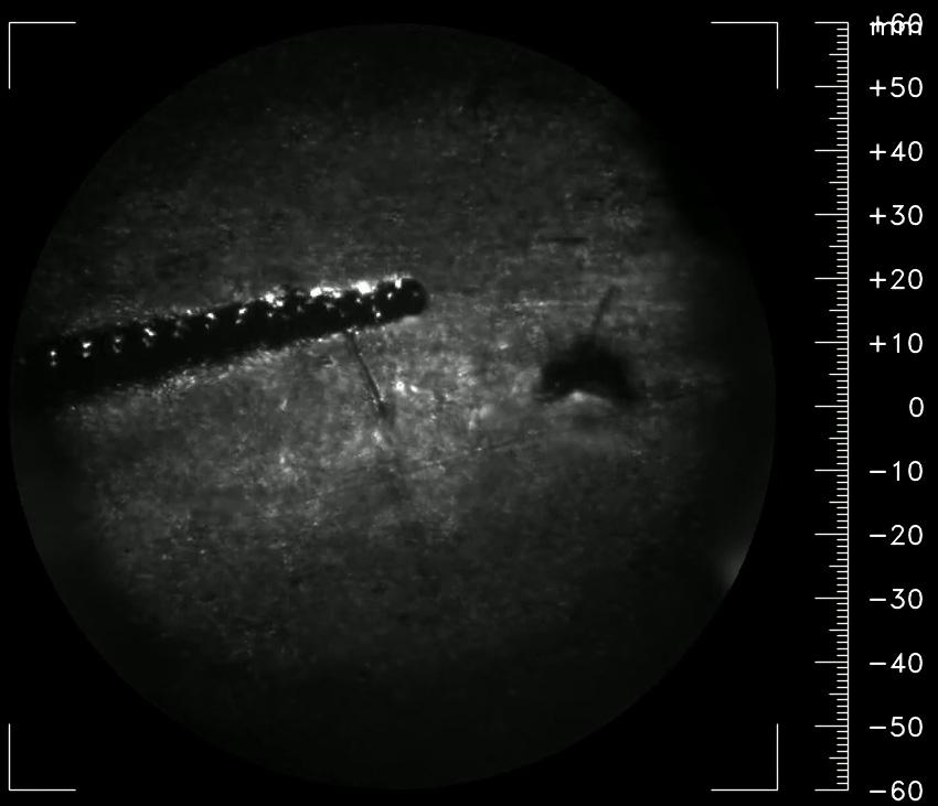
LineVu, a real-time visual monitoring system developed by Process Vision, addresses this blind spot. LineVu connects to existing tapping points, so no major modifications are needed. Quick and easy retrofit allows immediate benefits, LineVu provides continuous video surveillance of the gas stream, capturing mist formation, stratified liquids, and unexpected contamination that gas analysers miss. This visual data proves that relying on hydrocarbon dewpoint misleads operators. With real-time video, operators can make immediate adjustments to flow conditions and start-up procedures. For instance, if liquid is detected at
Figure 2. Heavy mist flow in a gas pipeline.
Figure 1. LineVu on a cross section of a gas pipeline.
the compressor entry, the operator can delay flow ramping, divert flow, or activate additional separation systems. This directly prevents liquid ingress, equipment damage, unexpected trips and shutdown with the associated emissions due to venting or flaring.
For operators, installation is a practical exercise: the camera can (ATEX and IECEx Zone 1/Class I Div. 1) bolts to a standard 1 in. NPT or flange tapping, a LineVu controller sits in the safe-area control room, and power/ethernet runs up to 100 m on 110 - 240 VAC or 24 VDC lines, making temporary or permanent retrofits possible without line shutdowns. For short-term trials, the portable ‘Discovery’ kit (camera, sun-shield, 24 V supply and fibre media-converter) can be mounted and removed within 2 hours, giving operators a lowrisk path to evaluate the technology before full deployment.
As midstream companies across the US begin to roll the technology out, they are unlocking business value. By introducing process cameras and AI models for real-time image processing. It ensures feed gas quality by detecting
liquid contamination early, allowing proactive measures to prevent compressor damage, venting, and flaring, thus improving reliability and availability of gas processing facilities. It also enables comparison of feed quality between two or more processing trains and detects upstream performance deterioration by integrating camera technology with conventional instrumentation.
With high-resolution process cameras installed to continuously capture video footage of internal gas pipeline conditions, images can be synchronised with process data to create a comprehensive dataset for analysis. The performance can be observed under various flow conditions, including routine operation, periods of low flow, compressor trips, and recirculation events. Identifying flow patterns such as mist or stratified liquids, as well as how each train responded to identical process inputs can be observed and ultimately correlated with upstream conditions, including pressure, temperature, and flow. Process data alongside image meta data is then correlated in a machine learning model to provide a comprehensive diagnostic tool to determine which part of a separation system (e.g. liquid level in the separator) has the greatest influence on liquid carryover.
Understanding flow regimes and predictive detection
A technical understanding of fluid dynamics further supports this approach. Two-phase behavior inside high-pressure gas lines is governed by the Froude number, the ratio of flow inertia to gravity. LineVu field data are plotted against the mixed-phase flow map where gas Froude numbers span 0.001 - 10 000 and liquid Froude numbers 10 -7 - 10 2 Distinct regimes emerge – stratified-smooth, stratified-wavy, mist, annular-dispersed, slug, bubble – each occupying a predictable Froude envelope. However, comparing the modelled mixed-phase flow maps with real world conditions in for example a 36 in. diameter pipeline does not confirm that the flow map holds true. The models, developed from tests in small diameter test loops do not necessarily apply to larger diameter real-world conditions can be very different. For instance stratified flow has been observed at very high velocities when the flow map would suggest that only mist flow is possible and mist flow observed at very low and even stationery gas flows.
Environmental and economic benefits
Beyond operational benefits, the environmental implications are substantial. Just 0.1 % liquid volume fraction in a 100 million standard ft 3/d line equals approximately 10 000 US gal d -1 of NGLs, worth millions in lost product for the supplier. Once in a pipeline transportation network, these liquids are liable to cause damage to gas turbine blades, clog fuel nozzles, filters, and seals. A survey of five gas-filter designs showed actual liquid ingress of 981-gal d -1, over 16 times the contractual separator limit of 0.1 gal million standard ft 3/d -1. At compressors, the UK HSE documented 71 dry-gas-seal failures across 38 compressors, each outage costing
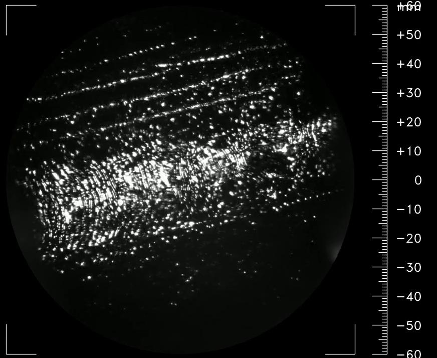
Figure 3. Stratified flow in a gas pipeline.
Figure 4. Stratified flow in a gas pipeline.
catgroup.net
US$60 000 - US$120 000 in repairs with the cost of lost production far exceeding the cost of repairs. Liquid ingress between seal faces was cited 100% failures. By alerting operators before liquids reach compressors, LineVu directly mitigates these avoidable expenses. When such liquids are combusted, leaked, or flared during incidents, the carbon intensity of the gas delivered increases dramatically. Visual systems like LineVu support ESG and methane intensity reporting by providing timestamped, verifiable records of pipeline conditions.
Enhancing operator safety
With live video, operators can see the amount of liquids present at the compressor entry at start-up or during pigging operations and manage the risk of compressor trips or worse a compressor failure much better. Holding off the ramp
up of flow until the liquids have subsided and ensuring the area around the compressor is evacuated when liquids are present. Visual proof of pipeline conditions helps operators satisfy the US EPA Greenhouse Gas Reporting Programme (GHGRP) Sub-part W, which requires equipment-level methane quantification and verifiable records of abnormal events. Because LineVu timestamps and archives every video frame, the footage supports ESG audits and voluntary methane-intensity metrics now referenced in many LNG and long-haul-pipeline contracts. It also underpins compliance with the ‘commercially free of liquids’ clause ubiquitous in interstate-pipeline tariffs, such as Cimarron River Pipeline’s gas-quality standard.
Integrating visual monitoring into gas quality assurance
Industry papers now advocate a dual-validation model, pairing real-time video with chromatograph-derived dewpoint data – to close the 186°F uncertainty gap inherent in thermodynamic calculations alone. Process Vision have already implemented automated scoring: a machinelearning model ranks liquid severity, scoring for mist flow and stratified flow separately. The data feeds heat-maps and alarms into cloud dashboards for remote decisionmaking and predictive maintenance scheduling.
In the first study of its kind, Process Vision have developed a diagnostic tool that correlates process data with the meta data from the images in a machine learning model. This provides a ‘digital twin’ of the process and ranks, in order of influence, which of the process parameters are affecting the level of liquid carryover. This can show which of the liquid levels in upstream separators needs to have improved control to avoid liquids being re-entering as the gas flows through the separator.
As regulators press for continuous emissions monitoring and operators accelerate digitalisation, systems that see flow regimes – rather than infer them – are positioned to become a standard layer of the gas-quality toolkit.
Conclusion
In conclusion, compressors represent both a vital and vulnerable part of the transmission network. Preventing contamination requires more than assumptions; when making safety and high value decisions, engineers need to make evidence-based decisions. LineVu delivers that evidence. With the ability to see the unseen, operators can improve control of liquid carryover, prevent compressor trips and stop emissions before they start, improving safety, lowering maintenance costs, and protecting the environment.
References
1. US Environmental Protection Agency (EPA). (2023). Inventory of US Greenhouse Gas Emissions and Sinks: 1990 - 2021. https://www.epa.gov/ ghgemissions/inventory-us-greenhouse-gas-emissions-and-sinks
2. EPA Greenhouse Gas Reporting Programme (GHGRP) Subpart W data. https://ghgdata.epa.gov/ghgp/main.do
Figure 6. Reviewing real time streaming from LineVu on a Discovery system.
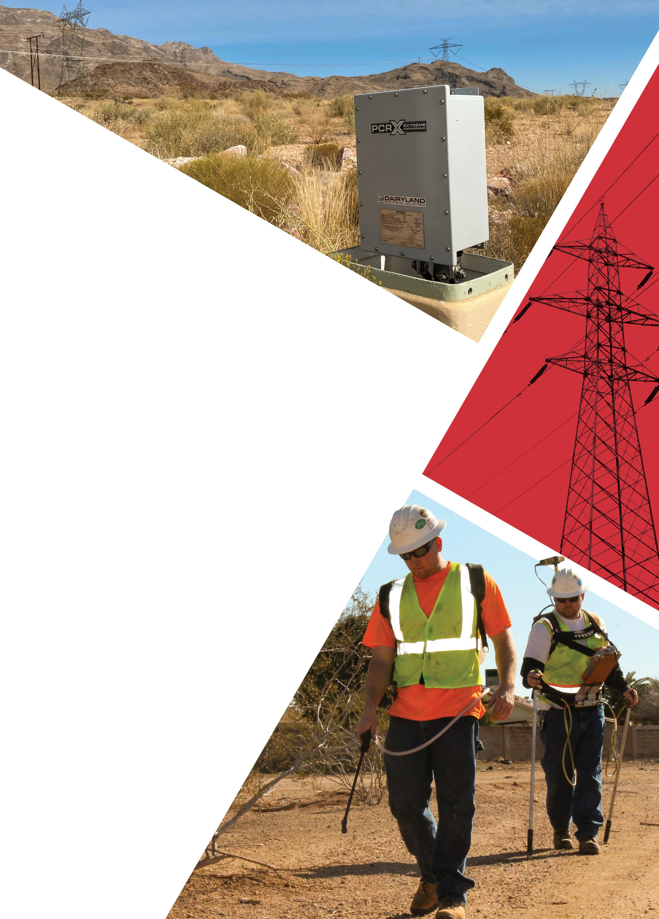
THE MOST SOPHISTICATED DECOUPLER IN THE WORLD
Dairyland’s PCRX is the most sophisticated decoupler on the market; offering the functions of standard decouplers while also eliminating capacitance delays during interrupted surveys. Unlike traditional decouplers, PCRX remains connected during testing, overcoming capacitive effects while maintaining protection for personnel and critical assets for the duration of the survey. This ensures accurate and timely potential measurements while still providing the rugged over-voltage protection, AC interference mitigation, CP isolation, and safety grounding expected from Dairyland decoupling products.
Henk de Boer, CTO, and Fabienne Ellington, VP Middle East and Asia Pacific, Strohm, the Netherlands, evaluate different innovative materials that are bridging the performance gaps in extreme environments.
The IEA’s Offshore Energy Outlook (2024)1 marks a notable shift from investment in shallow water to deepwater assets. As shale oil starts to level off, there is an increased need to tap into more expensive to produce oil in challenging and complex reservoirs. This increases the attractiveness of deepwater projects, as well as smaller onshore fields and less productive areas, but it comes with its own set of challenges.
As operators push further into harsher environments, the limitations of conventional steel pipelines are becoming more visible; corrosion, fatigue, and logistical challenges in remote locations are delaying projects and increasing the total cost of ownership. Thermoplastic composite pipes (TCP) are emerging as a credible, field-tested alternative that addresses these issues head-on.
TCP Jumpers have been successfully used for several years now, mainly for water injection, gas injection, or water alternating gas (WAG) applications. To enable the use of TCP Jumpers as production jumpers, Strohm developed an insulation solution which can be used in combination with either its carbon fibre and PA12 composite, or the next
generation high temperature resistant composite material based on carbon fibres and polyvinylidene difluoride (CF-PVDF).
Cold and high-pressure subsea fields
Recent developments show how insulated TCP solutions can maintain flow assurance in cold, high-pressure subsea
fields without compromising weight or flexibility. In a recent paper, thermoplastic composite pipe (TCP) producer Strohm presented its application towards an insulated production solution for temperatures up to 93°C (200°F) and the testing carried out to confirm the product viability for these extreme temperatures.
An optimal insulation solution for TCP must not only meet the required heat transfer coefficient (U-value), but also take the system’s on-bottom stability into account, given that TCP is relatively light. Additionally, the insulation must not negatively impact the TCP’s flexibility and its ease of installation, particularly when it comes to subsea pallet deployment. This means the insulation must provide adequate submerged weight while maintaining the installation efficiency of the system.
An insulation solution based on polyurethane half shells, with integrated ballast, was selected and further optimised during detailed engineering. In alignment with the standard for TCP (DNV ST-F119), a key element of the qualification was to prove the system’s predictability and validate its performance.
U-values were measured on bare TCP and on TCP with insulation. In both cases, during the test conditions, the measured U-value was found to be very close to the calculated values, therefore proving its predictability and validating its performance. In dry conditions the measured U-value was 1.0 W/m2K, corresponding to a U-value of 3.9W/m2K in submerged condition.
However, an optimal insulation solution for TCP must address more than just achieving a specific U-value. Due to TCP’s relatively low weight, on-bottom stability must also be considered. Additionally, the insulation should not compromise the installation benefits of TCP jumpers, particularly their compatibility with subsea pallet deployment. In other words, the optimal insulation solution must be flexible and easy to install – which are key features of the TCP Jumpers – and must have sufficient submerged weight when delivering the required insulation properties.
To meet on-bottom stability requirements, the TCP Jumper and its insulation covers must have a minimum submerged weight. However, since both TCP and common insulation materials are relatively lightweight, a thick insulation layer can significantly reduce system stability. To address this, carbon steel inserts are fully integrated into the polyurethane covers to increase the system’s submerged weight.
The two (top and bottom) polyurethane covers (polyurethane shell with integrated carbon steel inserts) are fixed to the TCP by super duplex straps. A thin layer of open-cell silicone foam is placed between the TCP and the shell to block water ingress in the installed configuration. Friction between the components, combined with the tension in the super duplex straps, is sufficient to prevent the covers from sliding under their own weight. The easy to assemble insulation covers can then be installed before the TCP is spooled onto the subsea pallet.
The use of insulation covers must not affect the system’s minimum bend radius, nor should it significantly increase bending stiffness. To ensure this, the polyurethane used must be considerably less stiff than the TCP itself, a key factor
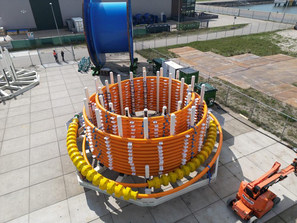
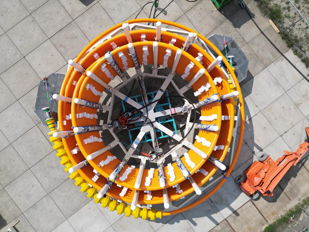
Figure 3. Aerial view of a TCP carousel.
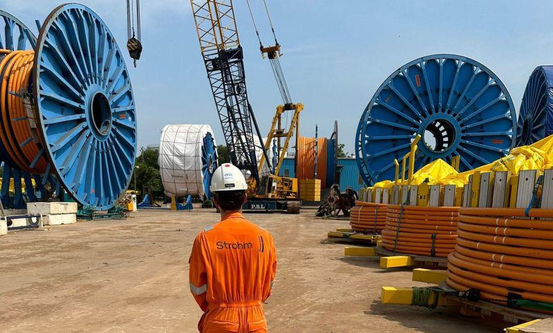
Figure 1. TCP carousel at Strohm’s manufacturing plant in the Netherlands.
Figure 2. TCP can be delivered in long lengths on a reel or a carousel.
We are running out of space...
Our inventory in sales & rental in pipeline equipment is out of this world. We have a huge amount of machines from all the big brands that are ready for worldwide delivery, or even further if you want...
You can build on BAUMA!
in selecting the appropriate polyurethane grade. Extensive simulations were conducted on the insulated TCP Jumper at both low and high temperatures to confirm the system remains easily spoolable onto a subsea pallet.
TCP Jumpers used in production
TCP Jumpers are a very attractive alternative for rigid or conventional flexible pipe jumpers. They not only have a significantly lower carbon footprint, but they also offer advantages in terms of total installed cost and schedule flexibility. The addition of external insulation and the ability to withstand temperatures up to 93°C allow TCP Jumpers to be deployed as production jumpers in higher-temperature environments.
Strohm’s Jumper on Demand concept further strengthens these advantages. This approach takes advantage of volume cost savings in the entire supply chain and involves shipping a continuous section of pipe which is subsequently cut to length and terminated in-country.
This modular, on-demand system supports fast-track field development, minimises installation complexity, and is particularly well-suited for dynamic project schedules or latestage tie-ins. Significant scheduling advantages can be gained by removing the need for detailed metrology and enabling rapid assembly of jumpers to the precise required length. Additionally, the lightweight, corrosion-resistant nature of TCP makes the solution ideal for challenging environments, while maintaining installation flexibility using simple deployment methods such as subsea pallets.
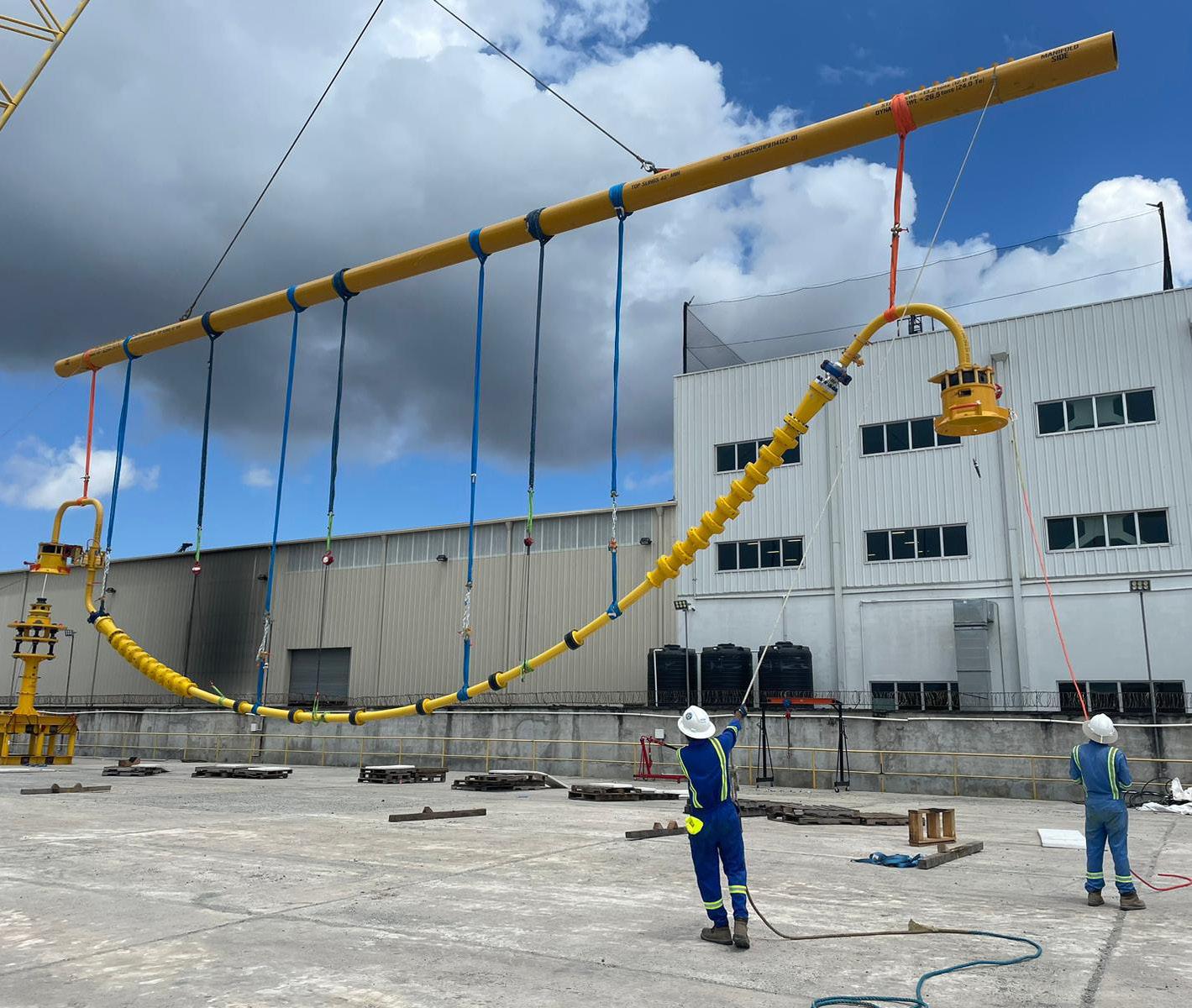
TCP technology has a growing reputation across the industry and is regarded as a breakthrough technology with an extensive track record. A prime example was a recent TCP Jumper deployment to South America where it was installed at depths of more than 1700 m and used for water alternating gas (WAG) injection.
The addition of external insulation and the ability to withstand high temperatures makes TCP a well-suited material for production jumpers in hotter environments.
First use of TCP for an onshore pipeline
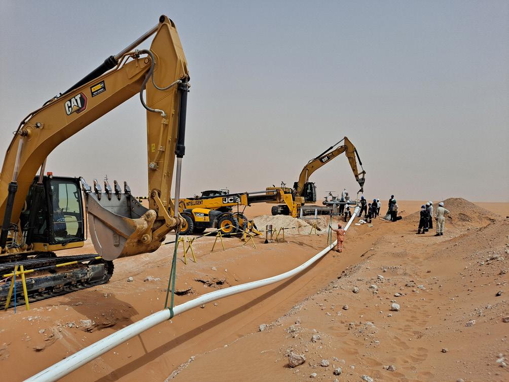
TCP is a versatile technology that is suitable for offshore and onshore deployment in challenging environments. The first use of TCP for an onshore pipeline in the Middle East earlier this year marks a significant shift in pipeline engineering, expanding the technology’s track record even further.
Strohm has been awarded a contract to supply 33 km of its TCP flowline to support the development of a gas plant in the Middle East, marking the company’s first commercial contract for onshore applications in the region.
The 6 in. glass fibre polyethylene composite pipe will be used for rich mono ethylene glycol (MEG) transport. It is produced in the company’s manufacturing plant in the Netherlands and terminated in the field using local workforce. The low weight solid pipe structure is immune to corrosion and has a smooth liner ensuring enhanced flow.
The contract was awarded following a series of material selection studies, which showed that TCP was the most suitable solution for the flowline, due to its demonstrated fluid compatibility, high qualification standards, lack of corrosion, and low carbon footprint. This represents a significant milestone for the company, and it reinforces its commitment to the Middle East as a strategic growth area and its role as a pivotal gateway to the broader markets in Asia and East Africa.
Figure 6. Onshore TCP installation in the Middle East.
Figure 5. The Jumper on Demand fabrication model.
Figure 4. TCP Jumper used for WAG injection.
A new generation of digital engineering tools
Supporting the material’s wider adoption across challenging environments, there is a new generation of digital engineering tools designed to streamline pipe design assessments during the Front-End Engineering Design (FEED) stage of projects, enabling engineers to evaluate the suitability of TCP for various applications quickly and accurately.
Strohm has recently launched TCP DesignerTM, a new web-based tool developed to help companies design and engineer thermoplastic composite pipes for their projects. The tool is made accessible to operators, installation contractors, and engineering houses. By inputting project-specific specifications, users can instantly generate datasheets with key parameters such as size, weight, stiffness, and minimum bend radius, enabling them to easily and quickly assess factors such as installation feasibility and in-place analysis. For instance, this allows the user to quickly assess the wide range of vessels available to install the lightweight TCP in any water depth.
The tool simplifies decision-making, reduces design iteration time, and supports the adoption of cost-effective, lightweight, and corrosion-resistant TCP solutions in energy infrastructure, and other industrial projects.
Advanced technologies for a changing industry
As the energy industry increasingly targets harsher
well locations, innovative technologies are playing a critical role in enabling safe, efficient, and cost-effective operations.
Strohm’s Jumper on Demand concept offers a fast, modular, and cost-effective solution for deploying jumpers without lengthy fabrication or detailed subsea metrology. Pre-qualified TCP jumpers are stored in stock, cut to the required length, and terminated in the field, enabling faster deployment and streamlined logistics. Complementing this approach, TCP Designer further enhances project agility by enabling engineers to quickly assess pipe configurations, insulation requirements, and installation feasibility. Together, these innovations represent a practical response to the industry’s growing demand for smarter, faster, and more resilient pipeline solutions.
According to Wood Mackenzie, deepwater production is expected to grow by more than 60% by 2030, reflecting a broader industry shift toward more complex reservoirs where traditional infrastructure struggles to keep pace.2 This leads to global demand for flexible, corrosion-resistant pipeline solutions rising in tandem. Considering TCP’s lack of corrosion, ease of installation and the system’s modular insulation design ensuring stability without compromising flexibility, the technology is well suited for the industry’s evolving needs.
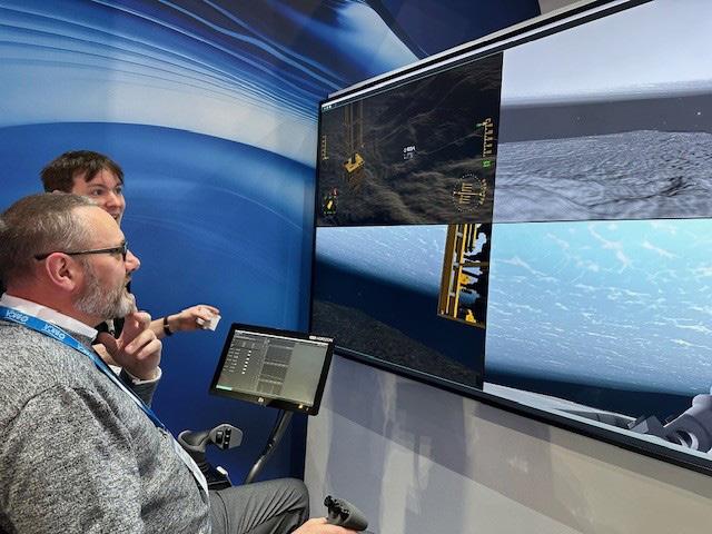
Roger Moore and Sara McQuillan, International Marine Contractors Association (IMCA), explore how IMCA is enhancing safety and competency in the offshore industry through updated training, guidance, and accreditation for ROV and inspection personnel.
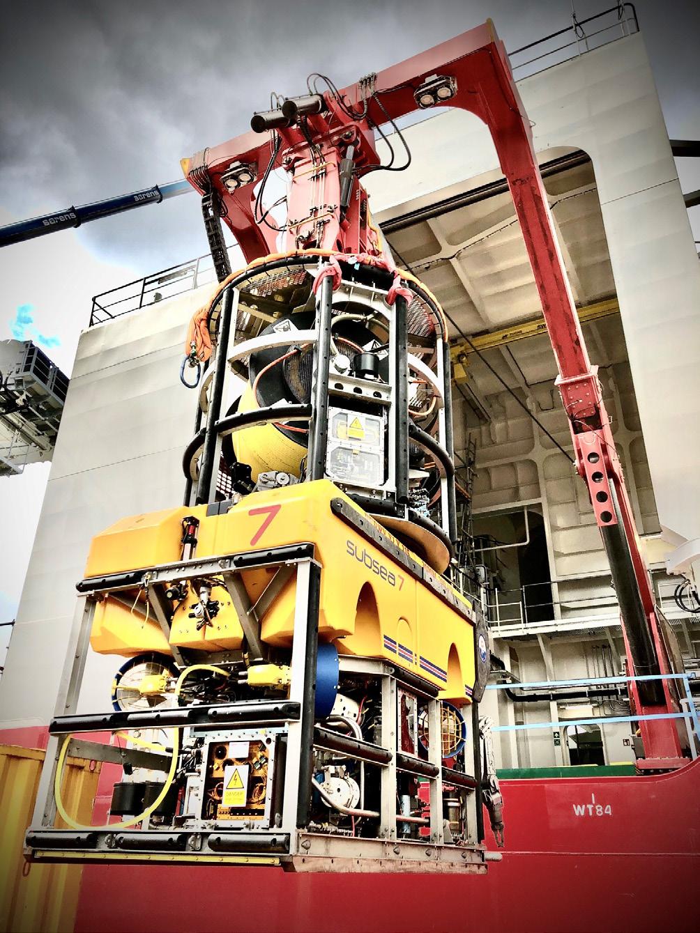
Remotely Operated Vehicles (ROVs) are essential work tools for IMCAs members serving the global offshore construction industry. Since their development in the 1960s by the US military, the technology and application of ROVs has advanced rapidly and today they are a vital component of oil and gas exploration and production (E&P); inspection, repair, and maintenance (IRM); and decommissioning projects.
Through these types of projects, ROVs have proven essential for the pre-installation, installation, maintenance, and removal of subsea pipelines. The technology continues to evolve with industry needs and advances in technology. In the decommissioning sector, aging subsea infrastructure is driving innovation with the development of new ROV tooling to interact with diver designed connections at places such as pipeline connections. Accessible technological developments are stimulating the use of remote operations, introducing new roles as remote ROV pilots and cutting-edge simulators are increasingly being utilised for bespoke training on ROV systems.
IMCA has a long history of supporting the ROV industry through its rapid development with a range of guidance and programmes available to our members driven by the expertise and feedback of our Remote Systems and ROV Division.
To continue the support for their membership and the wider marine contracting industry, IMCA has introduced a new suite of approval and accreditation programmes along with significant upgrades to existing guidance centred around Remote Systems and ROV Division and Competence and Training Division.
The new suite of approval and accreditation programmes includes revised ROV audit guidance (and a new digital platform), new competence guidance on Remote ROV Pilots, approvals for Remote ROV Pilot Training Courses, Class A ROV Simulator Systems, Original Equipment Manufacturer Training, new competency frameworks
for Inspection and Accreditation for in-house Competency Management Schemes. The overall aim is to improve quality and competency in the offshore industry to build stronger teams, facilitate development and enhance performance for a safe working environment.
IMCA currently publishes various technical guidance for ROVs along with competency frameworks for ROV roles. IMCA also offers approval of training courses achieved through a vigorous audit process to ensure quality in delivery and outcomes.
Part of the work of the Remote Systems and ROV division has been undertaking a comprehensive review of opportunities for
improvement within the industry in light of technological advances, which has resulted in the new range of approval and accreditation programmes as well as ensuring our current offerings remain fit for purpose.
Additionally, the Competence and Training Division has identified a need for competency frameworks for the offshore inspection industry. An underwater inspection engineer or controller is responsible for collecting, processing, analysing, and reporting inspection data of underwater structures.
These engineers play a key role in ensuring the safety and integrity of underwater pipelines, using advanced sensors and ROV technologies to identify issues like corrosion or damage early. Their expertise prevents costly repairs and environmental risks, while supporting maintenance and emergency response in increasingly complex marine environments.
To support this important area of expertise, IMCA will be publishing guidance for Subsea Inspection roles.
ROV system inspection
IMCA has recently republished its existing ROV audit guidance (R006) aimed at those owning and operating ROVs. After an extensive review by industry experts within the IMCA membership, the detailed guidance has been revised to ensure a comprehensive audit can be undertaken providing confidence for stakeholders.
The next phase of this programme is the launch of a digital system for undertaking these ROV system inspections (audits). The new auditing and inspection system for ROVs mirrors the long established IMCA marine eCMID scheme –an online database and inspection app providing the marine and offshore industry with standardised formats for vessel inspection. It offers a safety management system (SMS) ‘health check’ and can help improve the quality and consistency of inspections, as well as reducing the frequency of inspections on individual vessels through the adoption of a commonly recognised inspection process.
Each year sees the publication of an IMCA marine eCMID system annual report providing an analysis of vessel inspection findings, and reviews the quality assurance findings of the inspections carried out by the IMCA Accredited Vessel Inspectors (AVIs). The report aims to improve safety and operational standards by identifying common inspection findings, highlighting high-risk issues, and recommending improvements in inspection quality and vessel operations.
The publication of the revised and updated ‘ROV System Inspection’ document (IMCA R006) has included alignment with the eCMID platform to allow ROV owners/operators to take advantage of the same benefits as the marine eCMID. The electronic version is currently underway, so before long new ROV System Inspectors (RSI) will be completing inspections globally.
To support the implementation of the scheme, the company will be publishing guidance on the accreditation of ROV System Inspectors (RSI’s) who will be deemed as qualified to utilise the platform. To support these will also be guidance for IMCA-Approved Trainee ROV System Inspector Training Courses (T-RSI).
Figure 1. An SMD Simulator at the IMCA Global Summit 2024.
To align with industry needs, IMCA has expanded its existing competency frameworks with a new Remote ROV Pilot grade available to members (C005 - Guidance on Competence Assurance and Assessment: Remote Systems and ROV Division). This additional guidance was created in collaboration with industry specialists from remote operations centres and aims to provide a framework for assessing competency in this newly established role.
Alongside this, associated training approval is also being offered – ‘Requirements for IMCA-Approved Remote Pilot ROV Introductory Training Courses’ (IMCA R025), This is aimed at personnel graduating from university and intending to only undertake a remote pilot role from an onshore location in a Remote Operations Centre (ROC). The guidance outlines the requirements for training providers seeking IMCA approval to deliver remote pilot introductory training for ROV personnel. It sets clear expectations for course structure, content, learning outcomes, and assessment standards. The aim is to ensure a consistent, high-quality foundation for new entrants into the remote ROV industry.
Approval for ROV Class-A simulators
A new approval opportunity has been launched for ROV Simulators. ‘Requirements for IMCA-Approved Class A ROV Simulator Accreditation’ (IMCA R028) establishes the criteria for the accreditation of Class A ROV simulators, which are defined as realistic, fully immersive training systems.
The document sets out the minimum capabilities, performance benchmarks, and evaluation procedures for simulators to qualify as Class A. The goal is to ensure these simulators offer realistic, effective training that mirrors offshore operational conditions.
A range of scenarios would be designed for each pilot undergoing training on a simulator to cover a wide range of situations enabling them to practice how these operations are undertaken, and various issues can be interjected without risk to physical equipment. The risks for ROVs would be well documented within the course. This accreditation will help to assure industry confidence in simulator-based learning and will support the continued development of skilled, competent ROV personnel.
Approval of original equipment manufacturers training
IMCA will also be launching approval of original equipment manufacturers (OEM)
training. Currently manufacturers of ROV equipment typically offer familiarisation training of their systems with a comprehensive training course delivered in-house. To verify the quality of these training courses, IMCA will offer approval through a comprehensive review of the training provision including course outcomes, facilities and student assessment mechanisms. This guidance will support OEMs in achieving approval of their existing course and the future development of their training courses
Inspection competency frameworks
IMCA will be publishing new competency frameworks for the inspection industry: ‘Guidance on Competence Assurance and Assessment: Inspection Division’ (IMCA C021). This document
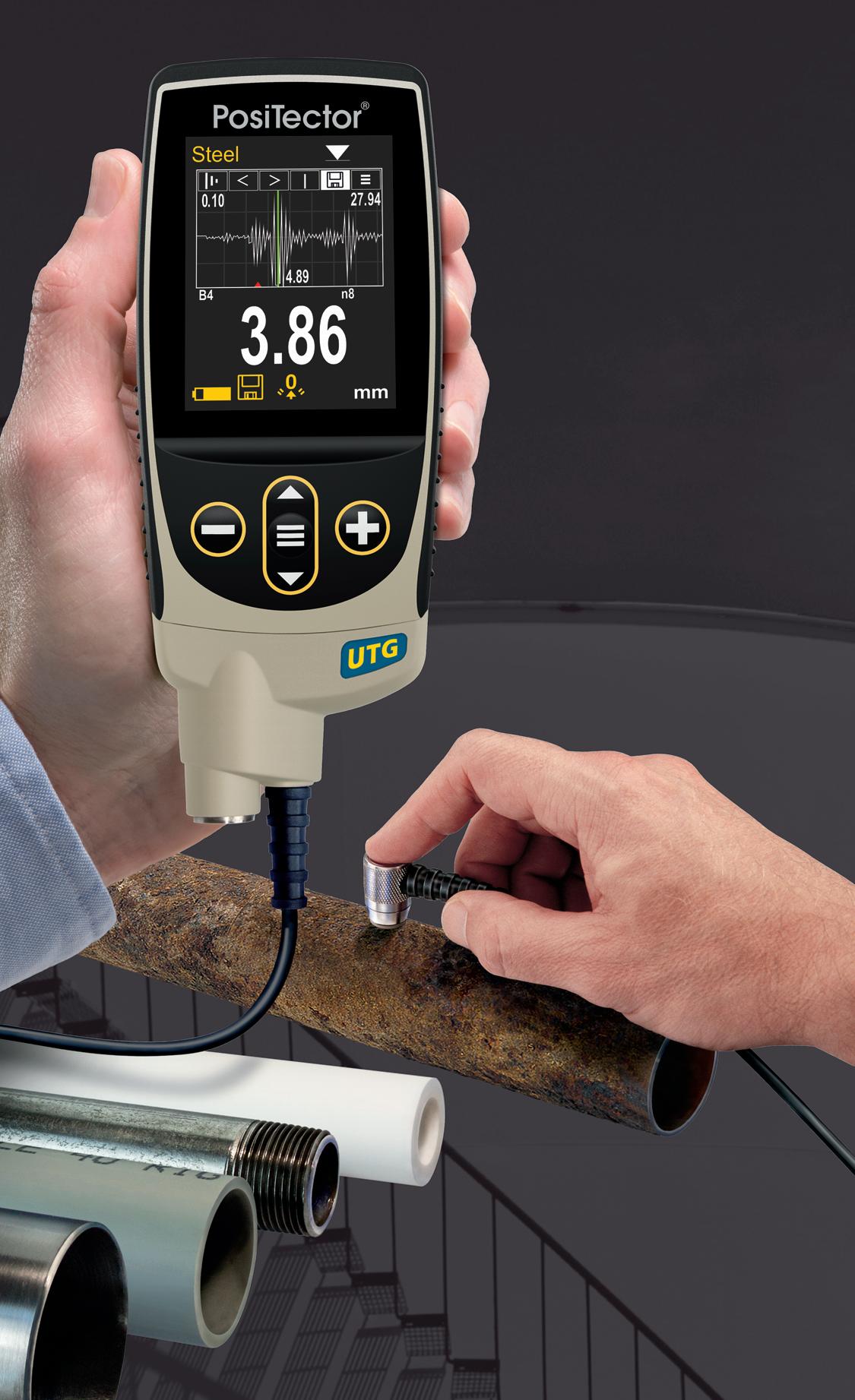
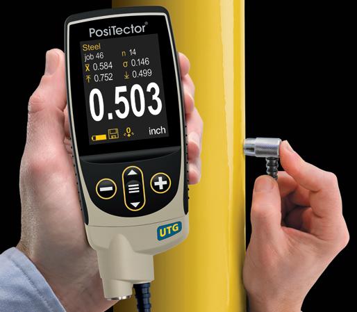
Ultrasonic Thickness Gauges
Ideal for measuring the remaining wall thickness and the effects of corrosion or erosion on tanks, pipes, or any structure
n 6 Models available including Corrosion, Xtreme, Multiple-Echo, Low Frequency, and Precision
n All models include Min Scan mode, memory, statistics, and USB
n Advanced models include: A-Scan, B-Scan, Bluetooth, and WiFi
n Weatherproof, dustproof, and waterresistant—IP65-rated enclosure
Scan here to learn more
PosiTector UTG M features Thru-Paint capability to quickly and accurately measure the metal thickness of a painted structure without removing the coating.
Award Winning Probe Interchangeability
PosiTector gauge body accepts ALL ultrasonic wall thickness, coating thickness, surface profile, environmental, soluble salt, gloss, and hardness probes manufactured since 2012.
+1-315-393-4450 n 1-800-448-3835 techsale@defelsko.com n www.defelsko.com
was developed with industry expertise and provides guidance on competence assurance and assessment for inspection personnel including data recorder, inspection engineer and inspection coordinator.
As part of this guidance IMCA has officially recognised three governing bodies on the career path from Data Recorder to Inspection Engineer: NORSOK (Norsk Sokkels Konkurranseposisjon), CSWIP (Certification Scheme for Inspection Personnel), and ABENDI (Brazilian Association of Non-Destructive Tests and Inspection).
By establishing this framework, IMCA sets clear offshore inspection competency standards to ensure consistency and help organisations assess and develop professional skills. These standards
aim to enhance safety, boost operational performance, and build stakeholder confidence across the industry.
CMS accreditation
A competent workforce is the backbone of a safe and efficient operation. A competence management scheme (CMS) is an indispensable tool for organisations seeking to build agile, highperforming teams equipped for future challenges. By providing a structured approach to identifying, developing, and leveraging critical skills, such schemes enable organisations to align talent with strategy, foster a culture of continuous improvement, and safeguard long-term success.
To support these systems, IMCA is introducing an accreditation for CMS. The new ‘Requirements for IMCA-Approved CMS Accreditation’ (IMCA C020) provides the framework for IMCA accreditation. It defines the standards a CMS must meet in terms of structure, documentation, assessment processes, and continuous improvement. The requirements are designed to ensure that companies can reliably assess and demonstrate the competence of their workforce.
Further to this, the CMS accreditation requires that personnel competency portfolios are transferable between IMCA member companies, which helps facilitate smooth transitions of personnel between organisations. IMCA C020 is part of a broader strategy to enhance operational safety, personnel development, and regulatory compliance across the marine contracting industry.
Julie Holmquist, Cortec ® Corp., discusses how the oil and gas industry can overcome the inherent corrosion challenges of this integral part of pipeline safety.
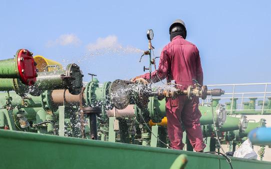
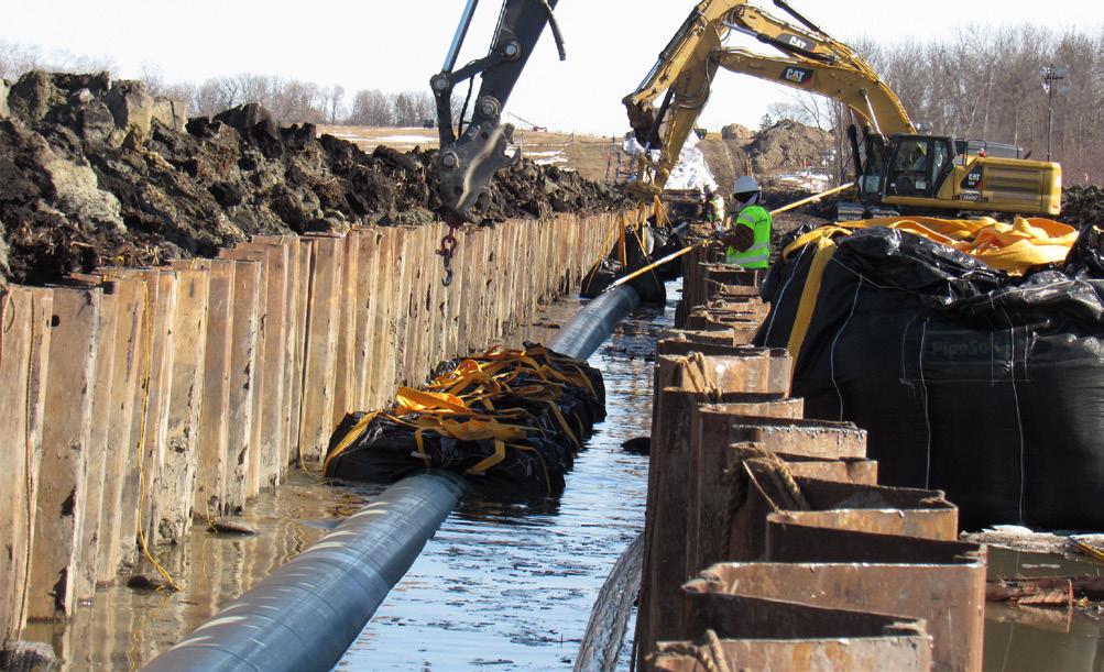
Hydrotesting. In the world of oil and gas, you can’t live with it… and you can’t live without it. Using water for pressure testing is a matter of course that ensures unending kilometres of pipeline have the strength and integrity to transport hazardous fluids cross-country, and even under the sea. Unfortunately, the very process intended to confirm pipeline safety and reliability can actually undermine its integrity by introducing moisture and leaving metal surfaces vulnerable to corrosion. That is why the right corrosion inhibitor is an integral part of the pipeline commissioning process and why manufacturers, contractors, and operators should know where and how a corrosion inhibiting additive fits into the overall hydrotest procedure.
Why is hydrotesting important?
Hydrotesting is such a vital component of hazardous fluid safety that it has become a pipeline rite of passage enshrined in standards throughout the world. In the US, the US Code of Federal Regulations includes a detailed list of requirements for hydrotesting hazardous liquid pipelines.1 A fact sheet from the US Department of Transportation Pipeline and Hazardous Materials Safety Administration (PHMSA) gives a good summary of these requirements, which include mandatory hydrotesting after construction or replacement, and before commissioning, to confirm that both the pipeline materials and the method of construction are sound.2 But this is not the only phase of hydrotesting. In some cases, the code also calls for manufacturers to ensure the integrity of non-pipe components by hydrotesting,3 an action taken before the component ever makes it to the construction site. Other relevant guidelines include the American Petroleum Institute (API) RP 1110 (recommended practice on pressure testing steel pipelines for gas and hazardous liquids)4 and ISO 10802 (an international standard for hydrotesting of ductile iron pipelines for oil transmission).5 Each standard is designed to evaluate integrity and confirm pipelines are strong enough to hold hazardous fluids/gases under pressure without leaking. Without these mandates for hydrotesting or some form of pressure testing, society would likely experience many more pipeline disasters from systems that fail under real life pressure.
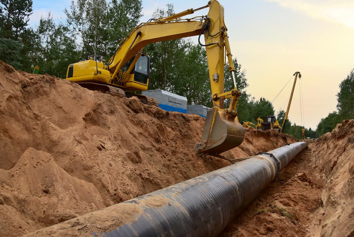
Basics of pipeline hydrotesting procedures
Hydrotesting should be done at several phases of a pipeline’s life cycle. As suggested above, the first occasion is the manufacturing phase, before the pipeline segments/components are sent to the field. The second time is before commissioning of a new or replaced pipeline segment. Hydrotesting also occurs periodically on operating pipelines to confirm the pipelines are still in good condition.6
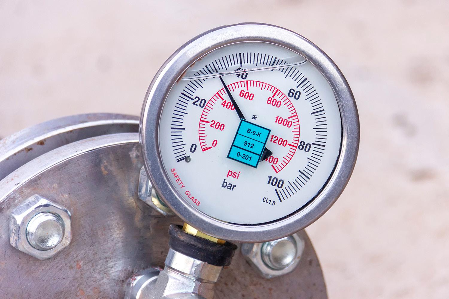
Understanding how hydrotesting is done provides a window into where and when corrosion protection may be needed. As the PHMSA fact sheet explains, the US federal code of regulations requires hydrotesting for several hours at 125% of the maximum operating pressure (MOP), plus additional time if the pipeline is not visible.7 However, hydrotesting can be even more specific. It can include strength tests and leakage tests. In strength tests, water is added for 2 - 8 h with pressure and temperature recorded. A leak tightness test takes even longer, with pressure measured every hour, typically for 24 h. As each pipeline segment is tested, the contractor must keep detailed records for the pipeline operator, and both the operator and contractor should sign a certificate that confirms successful hydrotesting was completed on that segment. When the pipeline has been completely tested, a full report with all certificates and data should be given to the operator for verification.8
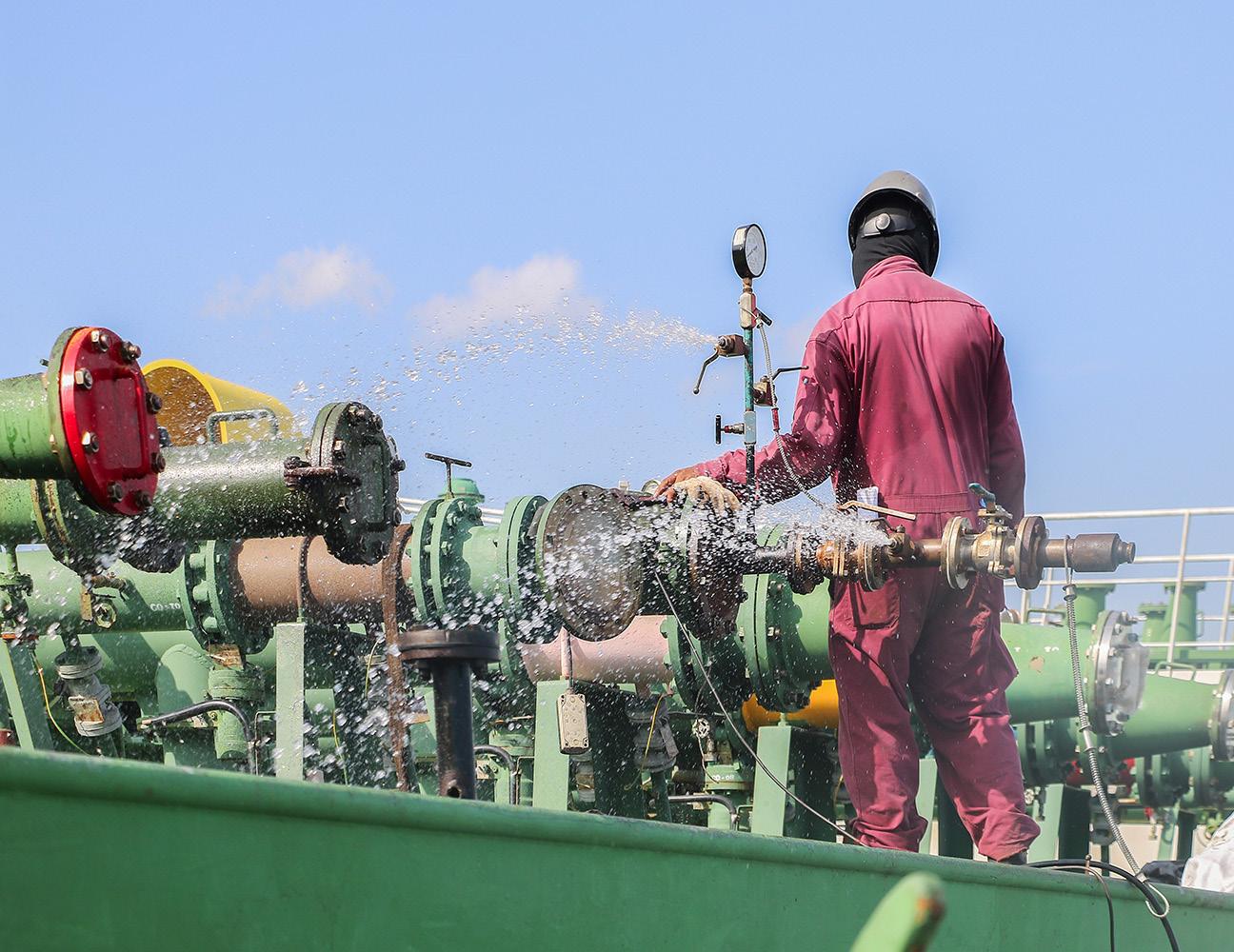
Figure 1. The very process intended to confirm vessel integrity can undermine it by introducing moisture and leaving metal surfaces vulnerable to corrosion. (Image courtesy of Cortec Corp.)
Figure 2. Pressure testing is such a vital component of hazardous fluid safety that it has become a pipeline rite of passage enshrined in standards throughout the world. (Image courtesy of Cortec Corp.)
Figure 3. Before commissioning, hydrotesting must be completed on each new segment of pipeline that is installed. (Image courtesy of Cortec Corp.)
Hydrotesting is also done on operating pipelines. One of the largest pipeline companies in the world explained that their process for hydrotesting crude oil pipelines is to dye the hydrotest water and place it between two pigs to seal it off from the hydrocarbons. This slug of water is then delivered to the pipeline segment that needs hydrotesting, and the pressure is increased while a ground and air team look out for any spraying or pooling water that indicates leakage. This is all executed with the safety of the surrounding communities and environment in mind.9
Why should a corrosion inhibitor be added?
Unfortunately, the very activity designed to ensure the safety of hazardous pipelines can also be their Achilles heel. As noted, water is often used for pressure testing (hence the term ‘hydrotesting’). Water in combination with oxygen and metal makes a perfect recipe for corrosion. The presence of salt or other contaminants increases the risk. Once corrosion starts, it is more likely to spread to other parts of the metal, deteriorating the internal surface and thinning the pipeline wall over time. While corrosion could create a leak by ‘eating’ a hole all the way through the metal, it could also simply weaken the pipeline enough to lead to a dramatic rupture when the corrosion-thinned wall can no longer withstand the pressure of the hazardous fluid. Either problem is dangerous and can be discouraged by adding a corrosion inhibitor to the hydrotest water.
Different timelines, different doses
When selecting a corrosion inhibitor for the hydrotest water, it is important to ask several questions. Is corrosion protection needed only during the hydrotest? Or will corrosion protection be needed for a longer period? Often, new pipelines are laid up for an extended period before they are commissioned. Sometimes the water is left inside the system for wet layup. Sometimes it is drained for a ‘dry’ layup. Other times it is literally dried out to prevent contamination.10 If corrosion protection is desired from the point of hydrotesting through layup (until commissioning), a higher dose of corrosion inhibitor will be needed. For example, for one corrosion inhibiting hydrotest additive, the recommended dose ranges from 0.3% by weight for protection during hydrotesting only, to 3% by weight for ongoing preservation for 1 - 2 years of preservation after hydrotesting. If the pipeline undergoes dry or wet layup in a very harsh environment, an even stronger dose of corrosion protection may be needed. The use of seawater vs fresh water will also affect additive selection, as some inhibitors may be specially designed for offshore use and seawater hydrotesting, but may not be designed for post hydrotesting preservation. In these cases, it may be desirable to rinse the pipeline and apply another corrosion inhibitor – whether it be in the form of an additive or a corrosion inhibiting fogging fluid – for protection until commissioning.
The corrosion inhibiting mechanism
The VpCI®-649 Series is one portfolio of corrosion inhibitors that is especially practical for hydrotesting. These hydrotest
additives not only provide active corrosion protection to the surfaces with which they come in contact but also leave behind a protective corrosion inhibiting film. This layer exudes corrosion inhibiting vapours that diffuse throughout pipeline internals and form a protective molecular layer in void spaces above the water level or throughout the drained pipeline. The corrosion inhibitor can be dosed at different levels for varying lengths of protection, which is why manufacturers can do themselves a favour by hydrotesting with enough corrosion inhibitor to provide ongoing protection as the pipeline segments travel to the installation site. Using a higher dosage of corrosion inhibitor is especially important when residual water is left inside a pipeline for extended periods. This reduces the need to completely dry the system for the sake of corrosion protection. In the case of the VpCI-649 Series, different tracers are available for easy detection to ensure proper concentration in the hydrotest water, allowing both the water and corrosion inhibitor to be reused in some cases for recycling efficiency and cost savings.
You can live with hydrotesting
Hydrotesting is an integral part of pipeline commissioning. It confirms the integrity of the system by exposing it to higher pressures than a pipeline typically experiences during operation. It is therefore an important precaution against pipeline failure and the danger posed to humans and the environment by the release of hazardous materials. Ironically, the exposure of metal to hydrotest water makes metal more vulnerable to corrosion attack, potentially undermining the integrity and service life of hydrotested pipelines over time. By implementing a corrosion inhibitor at every stage of hydrotesting – from manufacturing to installation to operation – manufacturers, contractors, and operators can make the most of their hydrotesting efforts while solving the corrosion conundrum easily and efficiently. Members of the oil and gas industry may not be able to live without hydrotesting, but thanks to corrosion inhibitors, they can live with it.
References
1. Code of Federal Regulations, Title 49, Subtitle B, Chapter I, Subchapter D, Part 195, Subpart E - Title 49, last amended 23 June 2025. Accessed 26 June 2025. https://www.ecfr.gov/current/title-49/subtitle-B/chapter-I/subchapter-D/ part-195/subpart-E
2. US Department of Transportation, Pipeline and Hazardous Materials Safety Administration. “Fact Sheet: Hydrostatic Pressure Testing”, revised 1 December 2011. Accessed 26 June 2025. https://primis.phmsa.dot.gov/comm/factsheets/ fshydrostatictesting.htm
3. 49 CFR 195, Subpart E.
4. American Petroleum Institute, “Pressure Testing of Steel Pipelines for the Transportation of Gas, Petroleum Gas, Hazardous Liquids, Highly Volatile Liquids, or Carbon Dioxide”, API RP 1110, 7th edition, 1 December 2022. Accessed 10 July, 2025. https://store.accuristech.com/standards/api-rp-1110?product_ id=2506637
5. ‘Ductile iron pipelines. Hydrostatic testing after installation’, BS ISO 10802:2020, 30 September 2020. Accessed 10 July, 2025. https://knowledge.bsigroup.com/ products/ductile-iron-pipelines-hydrostatic-testing-after-installation
6. US DOT PHMSA Fact Sheet.
7. US DOT PHMSA Fact Sheet.
8. All About Pipelines, ‘Precommissioning Hydrotest of Pipelines: Onshore and Offshore’, 23 July 2023. Accessed 10 July 2025. https://allaboutpipelines.com/ Article/PrecommissioningHydrotest
9. Enbridge, ‘Hydrostatic testing’, Accessed 10 July 2025. https://www.enbridge. com/projects-and-infrastructure/public-awareness/hydrostatic-testing
10. All About Pipelines
David Niehueser, Head of Business Line – Integrity Management Systems, and Simon Braun, Sales Manager, ROSEN Group, explore the successful transition to the NIMA Integrity Management Platform, ushering in a new era of secure, scalable, and insight-driven pipeline integrity management.
In the ever-evolving landscape of pipeline integrity management, digital transformation is no longer a luxury – but a necessity. For one major gas transmission operator in Oceania, the end-of-life of a long-standing software system presented both a challenge and an opportunity: modernising its asset integrity management approach while ensuring the highest data security and operational efficiency standards.
This article explores how the operator, in collaboration with ROSEN, successfully transitioned to the NIMA Integrity Management Platform – an ISO/IEC 27001:2022-certified solution –ushering in a new era of secure, scalable, and insight-driven pipeline integrity management.
The challenge: aging software in a data-intensive environment
For over a decade, the operator relied on a legacy software system to manage the integrity of its extensive gas transmission network. As the software approached the end of its lifecycle, the operator faced a critical decision: how to continue managing a growing volume of pipeline data and integrity activities without compromising on
compliance, safety, or efficiency, especially in the face of limited internal resources and staffing constraints.
Key requirements included:
) A centralised, accessible repository for pipeline data.
) Compliance with international standards and regulations.
) Enhanced decision-making capabilities through advanced analytics.
) A secure, scalable, and future-proof digital asset integrity management platform.
) Expert support enabling effective operations despite limited staffing.
The solution
ROSEN answered the call with a comprehensive solution: the NIMA Integrity Management Platform, which is deployed as a Software as a Service (SaaS) within the operator’s dedicated environment. Crucially, this environment is hosted on ROSEN’s ISO/IEC 27001:2022-certified IT infrastructure, ensuring that data security and information governance are embedded at the core of the solution.
Why ISO 27001 matters
In today’s hyper-connected world, where organisations rely heavily on digital systems, safeguarding sensitive information has become a mission-critical, strategic priority. Cyber threats are growing in frequency, sophistication, and impact, ranging from data breaches and ransomware attacks to insider threats and system vulnerabilities. In this environment, information security is not just an IT concern but a critical business imperative. Organisations must not only protect sensitive data but also demonstrate accountability and resilience while proactively managing related evolving risks.
ISO/IEC 27001:2022 is the globally recognised standard for information security management systems (ISMS). Certification to this standard demonstrates that an organisation has implemented a systematic approach to managing sensitive information, ensuring its confidentiality, integrity, and availability. The standard embeds a cycle of continuous (re-)evaluation and improvement, guaranteeing that security practices evolve in response to emerging threats, technological changes, and organisational growth.
For pipeline operators, where data accuracy and security are paramount, an ISO/IEC 27001:2022-certified solution affirms:
) Risk mitigation against cyber threats and data breaches: a structured framework for identifying vulnerabilities, implementing protective measures, and minimising the likelihood and impact of security incidents across digital infrastructure.
) Regulatory compliance with industry and governmental standards: a documented and auditable approach supporting national and international regulatory requirements, e.g. data protection, minimising legal exposure, and supporting long-term compliance sustainability.
) Operational resilience through structured information governance: clearly defined policies, roles, and procedures that
support business continuity, enable rapid incident response, and affirm the consistent protection of critical data assets.
) Stakeholder confidence in the integrity of digital systems and services: a visible demonstration of commitment to information security, enhancing trust among regulators, partners, investors, and customers in the reliability and maturity of digital operations.
Independent security validation
In addition to leveraging the infrastructure, the operator also initiated an external penetration test conducted by an independent auditor. This proactive measure was aimed at validating the robustness of the software’s security posture. The penetration test objectively assessed the system’s defenses against potential cyber threats and confirmed the platform’s resilience and compliance with industry best practices. This additional layer of scrutiny reinforced the operator’s confidence in the software platform’s ability to safeguard critical pipeline data.
From legacy to leading-edge: a seamless transition
The transition to the NIMA Integrity Management Platform was designed to be as seamless as it was transformative. ROSEN’s services ensured that the migration from the legacy system was smooth, secure, and comprehensive.
Key features of the transition:
) Web-based access: the SaaS model allows secure, browserbased access to the platform from any internet-connected device, enabling field teams, integrity engineers, and decision-makers to collaborate effectively, regardless of their work location.
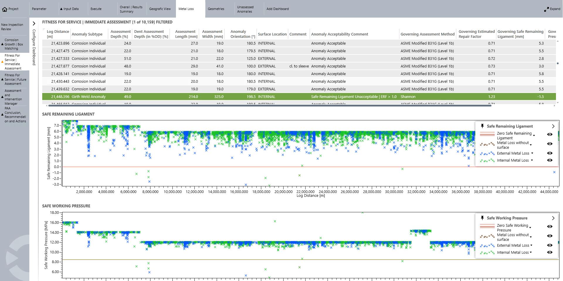
Figure 1. Pipeline Anomaly Assessment Workflow.
) Integrated integrity management workflows: replacing siloed software modules with fully auditable and transparent workflows – streamlining post-in-line inspection (ILI) integrity management processes and facilitating traceability, accountability, and regulatory alignment.
) Interactive dashboards: dynamic, real-time visualisations that provide clear, actionable insights into key integrity metrics related to fitness-for-service (FFS) evaluations, corrosion growth assessments (CGA), and other critical parameters – empowering data-driven decision-making and enhancing operational oversight.
) Data migration: seamless integration of over two decades of in-line inspection (ILI) and cathodic protection (CP) data into a centralised geodatabase structured according to the Esri® Utility and Pipeline Data Model (UPDM) – facilitating historical trend analysis and enhanced data governance.
) User enablement: a comprehensive hands-on training programme and continuous expert guidance to ensure rapid adoption and effective use of the platform to leverage its full capabilities confidently.
) Agile support: ongoing post-implementation services delivered through an agile, iterative framework – enabling continuous platform enhancement, swift adaptation to changing operational needs, and seamless, on-demand data integration and alignment based on both current and future requirements.
The benefits: from data to decisions
The operator’s transition, underpinned by ISO 27001-certified infrastructure, delivers many benefits that extend far beyond software functionality.
Seamless implementation and rapid adoption
The SaaS deployment model enabled quick setup, allowing users to gain immediate access to the software platform without needing complex on-premise installations or extended IT infrastructure. Its intuitive, user-friendly interface and integration into daily workflows minimised disruption to operations and accelerated user adoption.
Advanced integrity insights
Engineers now have access to a suite of integrity management workflows that could be extended to cover the entire asset integrity management cycle, from risk assessment to anomaly management and repair planning. The workflows are designed to provide deep, actionable insights into pipeline conditions by transforming large-scale data into actionable intelligence. This holistic understanding of asset conditions empowers operators’ engineers to make informed, data-driven decisions to enhance safety and proactively optimise maintenance strategies for longterm asset reliability. The decision-making is heavily supported and accelerated by the SaaS approach, enabling secure, real-time data sharing and supporting efficient, collaborative workflows across distributed teams and organisational entities.
Centralised, reliable data
By consolidating historical and future datasets into a single geodatabase, the operator now benefits from a reliable and consistent ‘single source of truth’. This centralised data repository eliminates data silos, reduces duplication, and ensures that all
stakeholders are working with the most current and accurate information available. The result is a fully traceable, verifiable, and complete record of asset data – a critical foundation for conducting accurate integrity assessments and demonstrating compliance with increasingly stringent regulatory requirements.
Scalable and cost-efficient data management
ROSEN’s data specialists manage and migrate critical asset data using advanced Geographic Information System (GIS) tools and industry-standard data models, guaranteeing high levels of data accuracy, consistency, and spatial integrity. The flexible, as-needed service model allows for precise and predictable budget planning, allowing operators to order services according to dynamic, operational demands. At the same time, it removes the need to invest in building, training, and maintaining a large, specialised in-house data team, reducing operational complexity and unnecessary overhead while ensuring access to expert-level task execution.
Ongoing support and long-term partnership
The SaaS subscription model includes continuous maintenance services, including but not limited to proactive system updates and local helpdesk support for timely issue resolution. In addition, the operator benefits from direct, on-demand access to ROSEN’s integrity and data management professionals, ensuring expert guidance is always within reach. The operator’s users play an active role in this process, providing continuous feedback and collaborating closely with the relevant subject-matter experts. This long-term engagement model fosters a genuine, collaborative partnership that ensures the software platform evolves with the operator’s needs and supports sustained operational excellence.
A model for the industry
This case study exemplifies how pipeline operators can futureproof their integrity management systems while maintaining the highest data security standards. By choosing the implemented solution built on ISO/IEC 27001:2022-certified infrastructure, the operator not only safeguarded its data but also laid the foundation for a more agile, transparent, and efficient integrity management process.
As the industry continues to grapple with the combined challenges of aging asset infrastructure, expanding data volumes, increasing regulatory scrutiny, and the need for digital transformation, this project offers a practical blueprint for success: combine cutting-edge technology with certified security practices and expert support to unlock the full potential of pipeline data.
Conclusion
The transition to the NIMA Integrity Management Platform marks a significant milestone in the operator’s digital journey. With ISO/IEC 27001:2022 certification as a cornerstone, the solution delivers compliance and security and the agility, insight, and scalability needed to thrive in a data-driven future.
For pipeline operators worldwide, the message is clear: secure, smart, and scalable integrity management is not just possible – it is essential.
Brendan Shanahan, Dexon Technology, Thailand, provides a case study on the 360° inspection of a gas pipeline that has been repurposed for hydrogen transportation.
The European Union (EU) is determined to become the world’s first climate-neutral continent by 2050. In pursuit of this goal, the EU has set ambitious milestones and implemented stringent policies to keep the region on course. Hydrogen is a critical element in the EU’s long-term strategy to become a global leader in sustainability.
The switch to hydrogen presents two primary challenges: providing sufficient infrastructure and ensuring its safe operation. To meet the EU’s ambitious goals, operators are repurposing existing natural gas and oil
pipelines for hydrogen transport. However, hydrogen’s unique properties bring a host of risks that require innovative solutions and rigorous inspections, particularly for pipelines not built for hydrogen.
This article will examine the increasing importance of repurposed pipelines for hydrogen in Europe, the challenges they present, and how Dexon recently ensured the integrity of a 12 in. hydrogen line through a comprehensive inspection.
Repurposing lines for the future of energy
To combat climate change and reduce reliance on fossil fuels, Europe is pursuing green alternatives. Hydrogen plays a central role in this transition, with plans for a Hydrogen Backbone network spanning 31 500 km by 2030. Hitting this target will demand a mix of innovation and practicality.
Why repurpose pipelines?
Building new hydrogen pipelines is costly and timeintensive. A planned 70 km hydrogen pipeline connecting France and Germany is estimated to cost €110 million and take three years to complete. And that is just the estimate. Infrastructure projects often run well past their deadlines and over their budgets. Replicating this on a larger scale would require decades and billions of euros. Furthermore, constructing new pipelines runs counter to the waste-reduction ethos driving the green shift.
Repurposing existing natural gas pipelines provides a faster, more cost-effective, and greener alternative. 60% of Germany’s planned 9040 km hydrogen grid will consist of converted pipelines, allowing the country to accelerate its transition without breaking the bank. Similar strategies are being adopted across Europe, making retrofitting a cornerstone of the hydrogen transition.
The dangers of hydrogen
Hydrogen’s properties make it highly efficient as an energy source, but they also make it exceptionally volatile. Compared to methane, hydrogen has:
) 35°C lower ignition temperature.
) 14 times lower required ignition energy.
) 12 times higher explosive potential.
Other issues compound these dangers. Hydrogen’s tiny size requires higher operating pressure, makes it more vulnerable to leaks, and enables it to ignite from gaps as small as 0.2 mm. In addition, hydrogen embrittles many metals, accelerating crack formation as the molecule penetrates the material.
These risks have consequences. The EU’s Minerva Database has recorded over 700 hydrogen incidents globally, resulting in more than 150 fatalities. As hydrogen use increases, so too will accidents, particularly if operators and regulators do not cooperate to ensure a safe transition.
2023 alone witnessed seven hydrogen incidents. In Austria’s Lebring Industrial Area, a hydrogen tank exploded
Figure 2. Hydrogen embrittlement occurs when hydrogen atoms penetrate the metal’s structure, weakening it from within and increasing the risk of cracking or sudden failure under stress.
and ripped through the surrounding area. One employee was injured, and a shockwave was felt 3 km away. These and other explosions underscore the need for rigorous safety measures.
Repurposing natural gas pipelines
Retrofitting natural gas pipelines for hydrogen transport involves addressing hydrogen’s unique properties. A main factor is embrittlement. Operators must assess pipeline materials for susceptibility. Some materials are resistant, such as austenitic stainless steels and nickel alloys. Other materials, such as carbon steel, may need to be covered with internal protective coatings or polymer liners to reduce embrittlement risks.
Another concern is higher operating pressures. Joints and welds might require strengthening to handle higher pressures and minimise leakage, while engineers might replace or reinforce compressors and seals. Advanced leak detection systems are installed to monitor for hydrogen leaks in real-time.
Finally, operators must implement new inspection and maintenance protocols to ensure the retrofitted pipeline’s integrity over its lifespan. This need is particularly pressing for operators who have not reinforced their pipelines. At present, regulations have lagged behind technology.
Challenges of inspecting hydrogen lines
Inspecting hydrogen pipelines requires specialised tools and expertise. Cracking is the primary concern due to the molecule’s tiny size, its ability to diffuse into metals, and the high operating pressures. This risk requires in line inspection (ILI) tools with high-resolution crack detection capabilities to catch threats before they become disasters.
Ultrasonic testing (UT) is the gold standard for crack detection. The latest generation of UT crack detection tools uses crack tip diffraction to identify all crack types and size them. Crack tip diffraction works by measuring the time it takes for a sound wave to bounce back to a transducer, calculating the characteristics of defects based on irregularities in the signal.
UT crack tip diffraction tools, however, have complex designs and require a liquid medium to operate. Most operators are hesitant to introduce moisture into hydrogen pipelines, given that hydrogen readily bonds to water and can compromise the pipe.
Despite these risks, liquid-based UT tools are the most viable option. Magnetic flux leakage (MFL) and electromagnetic acoustic transducer (EMAT) UT are the two competing alternatives. MFL tools operate with ease in gas pipelines since they rely upon magnetics rather than ultrasonic waves and are typically simpler to design and operate, but this technology struggles to accurately identify and size small cracks.
EMAT can operate in gas and detect cracks, but the method cannot reliably size cracks. Present EMAT tests report an accuracy of 55% at sizing ± 1.1 mm cracks at 80% confidence.
Given these restrictions, clients are increasingly selecting UT crack tip diffraction tools because they offer the most accurate and precise measurements. This is particularly true for hydrogen lines prior to being brought online, as new lines do not need to worry about lost revenue from longer shutdowns.
The importance of inspecting repurposed lines prior to operation
Given hydrogen’s volatility and the complexities of retrofitting lines, thorough inspections are nonnegotiable. There are two primary reasons for pre-operation inspections:
Ensuring safe operation
Pipeline refurbishments typically involve extensive modifications, which increase the likelihood of defects. 17% of all pipeline incidents are caused by external damage, with another 44% caused by material or equipment failure, such as weakened welds or poorly fitted gaskets. Engineers have protocols in place to ensure such damage does not go overlooked, but no protocol is perfect. A high-resolution in-line inspection (ILI) is the final safety check, ensuring that operators will not have a nasty surprise waiting for them.
Establishing a baseline
Initial inspections are critical to document existing defects and their locations. These measurements allow operators to monitor the progression of defects over time. With this information, they can anticipate issues and confidently extend asset service life.
Figure 4. Example of a 14 in. magnetic flux leakage tool. MFL tools use powerful magnets to send a magnetic field through the pipe wall and check for leaks in that field that could signal defects.
Figure 5. The tool used in the hydrogen pipeline inspection that combines crack tip diffraction UT (middle section) and metal loss (far-right section). The crack section induces shear waves in the pipe wall, while the metal loss section uses longitudinal waves.
ACOUSTIC TECHNOLOGY
Propipe are industry leaders in Acoustic technology. Supplying Acoustic pingers and multiple receiver types for tracking and locating pipeline pigs subsea.
Acoustic pingers can also be linked to SMART Gauge systems to detect pipeline defects and anomalies in real time.
Case study: Dexon’s inspection of a hydrogen line
Dexon recently helped conduct a 360° inspection of a pipeline repurposed for hydrogen in France. The 12 in. underground pipeline, built in the 1960s, connects a tank terminal to a distribution centre. Teréga, which is one of the leading gas operators in France, was preparing the line for hydrogen transport, and the operator required a comprehensive inspection to meet EU safety standards (ASME B31.8; DVGW G 464, etc.).
The inspection process
The inspection followed a four-step process:
) Hydrostatic testing.
) Cleaning and gauging.
) UT inspection.
) Data analysis.
Hydrostatic
testing
The operator first conducted a hydrostatic test to confirm the line’s pressure tolerance. The test was conducted at 60 bars, 1.5 times higher than expected operating pressure. The pipeline successfully passed the hydrostatic test.
Cleaning and gauging
Following the hydrostatic test, Dexon was tasked with cleaning and gauging the line. Since the line had never been inspected before, it lacked the necessary infrastructure for ILI. Dexon collaborated with the operator to design and install custom launchers and receivers for the tools.
The location of the line made this installation tricky, as it was located in an industrial area with confined spaces. Dexon’s engineers drafted three separate designs and collaborated with the client to determine which would be best.
Once the operators installed the launching equipment, cleaning began. Clean lines are essential for UT tools to operate at maximum resolution. Debris accumulating on the inside of the pipe can disrupt the signal and lower its
accuracy. Two foam pigs, propelled by water, were run to clean the line.
Next, inspectors sent a gauging tool through to ensure that the pigs would not get stuck in the line. Gauging tools have aluminium plates that record any geometric restrictions in the pipeline as it passes through. When the tool returned with minimal damage, engineers deemed the line safe for the stars of the show: UT.
The UT inspections
Dexon deployed two tools:
) UT-CD Hawk (circumferential and metal loss): designed to detect circumferential cracks and metal loss, this tool provides a detailed overview of the line’s structural integrity.
) UT-CD Hawk (axial): focused on identifying axial cracks, this tool complemented the circumferential tool to ensure no crack went unnoticed whatever its orientation.
With their inspection fleet, Dexon conducted a comprehensive inspection of the pipeline, assessing geometric defects, metal loss, and circumferential and axial cracks. The inspection followed the rigorous standards recently introduced by French regulators. Following the runs, data analysts remotely accessed the data and confirmed that the data was acceptable. Once receiving confirmation, the operator dried the pipeline to prevent corrosion.
Data analysis
A combination of software and experienced data analysts reviewed the inspection results, identifying defects and prioritising repairs. This detailed analysis provided Teréga with actionable insights and a baseline for future inspections.
As a final step to be absolutely sure of their pipeline’s safety, the operator excavated sections of the line to verify the accuracy of the reports. As of writing this, the verification process is ongoing.
Conclusion
The inspection of this hydrogen pipeline highlights the complexities of bringing repurposed pipelines online. Operators are rightfully reluctant to use water due to its corrosive effect, but given hydrogen’s highly volatile nature and its ability to accelerate cracking, providing the highest resolution should be a priority for operators. This fact is especially true for pipelines that are not yet in operation. By combining advanced tools with meticulous preparation and analysis, Dexon ensured the line was ready for safe operation and paved the way for Europe’s hydrogen future.
Reference
1. https://www.h2inframap.eu/
Figure 6. A- and C-Scan data from a crack detection run. Defects are matched to the odometers, which allow the operator to identify their location for repairs or to track them over time.
Anshul Godha and Paula LePore, Parker Hannifin, suggest ways to understand and mitigate stress corrosion cracking (SCC) and hydrogen embrittlement (HE) in stainless steels.
Environmentally assisted cracking, particularly in the forms of stress corrosion cracking (SCC) and hydrogen embrittlement (HE), represents a significant challenge in various industries, leading to unexpected and potentially catastrophic failures. The problem has intensified in recent years due to more demanding applications, harsher environments, and technology changes. Stainless steel grades, such as 316/316L, have
been the materials of choice for the energy markets (including oil and gas) for decades. These grades can often be especially susceptible to SCC and HE. Unfortunately, the damage caused by these forms of corrosion can be hard to detect early and diagnose in the field, allowing it to propagate to the point of unexpected, catastrophic leaks and spills. Such catastrophes have safety, environmental, productivity, and profitability implications.
Understanding the factors contributing to corrosion
The occurrence of SCC and HE is fundamentally dependent on the simultaneous presence of three key factors: a susceptible material, a corrosive environment, and tensile stresses. Eliminating any one of these factors can effectively mitigate corrosion.
Material susceptibility
The microstructure and chemistry of stainless steels play a crucial role in its susceptibility to SCC and HE. Factors such as sensitisation, the presence of large sulfide inclusions,
carbides, nitrides, or significant amounts of ferrite can be highly detrimental, accelerating the corrosion damage.
Corrosive environment
Aggressive environments increase the likelihood of SCC and HE. Higher temperatures and high concentrations of chemicals such as chlorides, sulfides, hydrogen sulfide – all of which are typical in offshore environments – can hasten the pace at which SCC and HE can occur.
Tensile stress
Sustained tensile stress is a prerequisite for SCC. As the total tensile stress increases, so does the risk of SCC and HE. These tensile stresses can result from material strengthening (for example during hot/cold working), machining, assembly, or service. The presence of sharp edges, corners, or other stress concentration ‘magnets’ can also increase the severity of the stresses in a material.
Different types of environmentally assisted cracking
Cracking due to corrosion can appear and propagate in different forms. Branch-type cracking is usually the first clue that you are dealing with SCC and/or HE. Determining exactly what type of corrosion you are dealing with and what caused it depends on how it looks and propagates, where the part was installed, environmental conditions, and duration. Understanding the underlying mechanisms is crucial for effective mitigation.
The four most common types of SCC are chloride SCC, HE, sulfide SCC, and caustic SCC.
Chloride SCC
This is the most common form of SCC. It is typically intragranular and most often appears in nearshore and offshore chloriderich environments, in high-strength stainless steels (Figure 1 [a]). Typically, cracking will show up sooner in cold-worked steel compared to annealed steel. Cracks can form wherever there is a weakness in the steel, such as a pit or an inclusion. The chlorideattack can cause the metal ions to degrade, eventually leading to cracking. There are several ways to test for chloride SCC, with the most common ones being:
) ASTM G36: Standard Practice for Evaluating Stress Corrosion Cracking Resistance of Metals and Alloys in Boiling Magnesium Chloride Solutions.
) ASTM G129: Standard Practice for Slow Strain Rate Testing to Evaluate the Susceptibility of Metallic Materials to Environmentally Assisted Cracking.
HE
This is considered one of the most severe types of cracking at low or ambient temperatures, and typically appears intergranular in onshore and offshore applications (Figure 1 [b]). It can be found in high-strength steels, titanium alloys, or cold worked stainless steel. It forms when tiny hydrogen atoms close to the surface of the metal diffuse into the metal and combine to create much larger hydrogen molecules. The molecules create a stress field around them that eventually causes the cracking. Testing can be performed either by comparing the ease of uptake of hydrogen
Figure 2. Copson curve showing the effect of nickel content on the resistance to SCC of various stainless steels.
Figure 1. Microstructures showing different types of environmentally assisted cracking (chloride SCC [a], HE [b], sulfide SCC [c], and caustic SCC [d]).
or permeation (ASTM G148) or by checking the effect of the permeation/diffusion of hydrogen on the mechanical properties of the metal (such as in ASTM F519).
Sulfide SCC
This can appear inter or intragranular and is most common in sour service environments where high-strength stainless steels are often used. A typical crack due to sulfide SCC is shown in Figure 1 (c). It is most severe at low or ambient temperatures. It is like HE, in as much as it is caused by hydrogen atoms diffusing into the metal. However, with this type of corrosion, hydrogen sulfide is also present in the environment. Hydrogen sulfide gas acts like a hydrogen recombination poison, preventing hydrogen atoms from combining outside the metal. This causes more of the atoms to diffuse within the metal thus increasing the probability of cracking to initiate. There are multiple test methods, depending on the alloy, environment, and application. NACE MR0175/ISO 15156 and NACE TW0177 lists some of the most common test criteria depending on the CI-concentration, pH levels, temperature, and other factors.
Note that the NACE guidelines focus on sour environments containing hydrogen sulfide, but their specific guidelines depend on the material, environment, and application. Among other things, NACE limits hardness which indirectly also restricts the material strength and therefore its general usefulness, especially in pressure retention.
Caustic SCC
This is most often seen in onshore applications, can be interor intragranular. A typical crack is shown in Figure 1 (d). It can be seen in carbon and low alloy steels, as well as in stainless steels. It often occurs in the presence of caustics such as sodium or potassium hydroxides. Testing is usually done by exposing the material to the caustic environments and conducting a slow strain rate testing such as ASTM F519.
Mitigation strategies
Mitigating SCC and HE involves targeted approaches to address material susceptibility, environmental aggressivity, or tensile stresses. The good news is that there are several ways to monitor and manage SCC and HE. While some of these involve added cost, these mitigation techniques protect against the costs of a major leak (including the downtime).
Stress-related remedies
The first strategy is to reduce tensile stresses any way you can. One way is to increase the design thickness. Keep in mind that, while this option will minimise stress concentration, it will also create design complications and increase machining costs and weight. Stress relief can also be accomplished mechanically or thermally, although these approaches also increase machining costs and are limited by the alloy you are using. One can also choose to minimise cyclic stresses, again realising that this will incur design complications. Wherever possible, minimising stresses in the materials can have a very positive impact in reducing the chances of stress cracking.
Material-related remedies
Material selection plays a critical role in corrosion protection. Typically used 300 grade stainless steel grades, such as 316/316L, are considered susceptible to SCC and HE in the cold worked condition. For stainless steels, significant improvement in SCC resistance is seen with alloys <7% nickel content such as super duplex 2507, or >20 % nickel content such as superaustenitic 6Mo alloys. The role of nickel content is shown in Figure 2 also known as the Copson Curve. Additionally, applying a solution heat treatment to welds can eliminate weld sensitisation and residual stresses within the weld. Lastly, wherever possible, using annealed materials always helps with increasing the resistance to SCC and HE.
Environment-related remedies
A third strategy is to modify the environment, although this may not be realistic in most applications. In some cases, controlling the environment can involve reducing dissolved oxygen levels. The use of corrosion inhibitors (e.g. silicates, nitrates, phosphates, carbonates, iodides, and sulfites) can effectively prevent chloride SCC. Operating at lower temperatures can decrease the severity of corrosion. Reducing the concentration of corrosive elements, such as chlorides and hydrogen sulfide, is also beneficial. Cathodic protection can be employed to prevent crack initiation in some instances.
Future trends in corrosion control
Recognising the significant environmental and financial toll of corrosion, there has been a lot of research that has been conducted both in academia and in industry. Parker is an example of a manufacturer that has tested numerous corrosion-management technologies. Most recently, the company introduced SuparShield™, which is specifically created for cold worked 316 stainless steels and does not result in any pressure derating while providing corrosion resistance improvements. It is not a plating or a coating, so it cannot be scraped off. It also improves fatigue resistance, resulting in greater material integrity.
SuparShield takes a comprehensive approach to mitigating SCC and HE in even the harshest applications for all energy markets related to fluid conveyance. The in-lab and in-the-field results have been impressive, demonstrating a 20 times improvement in service life. Not only has it been shown to limit stress cracking, but Parker has also documented improvements in other types of corrosion such as pitting. Plus, there were no reductions in material strength or working pressures.
Conclusion
SCC and HE are known as the silent threats because they can cause significant damage but are hard to detect in the field. Understanding the mechanisms that cause corrosion and being proactive in identification, mitigation, and management can save lives, downtime, and money.
There are several approaches that have yielded at least short-term positive results in delaying or preventing SCC and HE, but better alternatives are still needed. Companies like Parker are continuously working to improve the options with SuparShield representing the latest success story.
A podcast series for professionals in the downstream refining, petrochemical, and gas processing industries
LISTEN NOW
Sponsored by
EPISODE 9
Brandon Stambaugh, Owens Corning Director for Technical Services, discusses engineers’ demand for education and training to support three critical phases that affect the performance and longevity of insulating systems.
EPISODE 10
Lara Swett, Vice President of Technical & Safety Programs, American Fuel & Petrochemical Manufacturers (AFPM), explains how the downstream sector continues to improve its process safety record.
EPISODE 11
Graham Faiz, Head of Digital Energy, DNV, explores the current state of digitalisation in the energy sector and the key drivers behind digital transformation. Graham considers how companies can move from pilot projects to full-scale deployment of AI and digital tools.
EPISODE 12
Omar Sayeed, Centre of Excellence Leader for Reliability, and Rahul Negi, Director of AI and Industrial Autonomous, Honeywell Process Solutions, consider how new, innovative technology can help to overcome some of the challenges facing the downstream oil and gas sector.
Tim Hill, Commercial General Manager,
Nucor,
addresses why American-made steel is the strategic choice for building oil and gas pipelines
In today’s volatile economic and geopolitical environment, sourcing American-made steel for oil and gas pipelines has become a strategic imperative.
From mitigating supply chain risks to improving project delivery timelines, domestically produced steel offers US energy infrastructure developers a vital edge. For project leaders aiming to de-risk construction, meet evolving regulatory expectations, and strengthen long-term energy resilience, selecting American-made steel early in the project lifecycle eliminates supply uncertainty and ensures that projects can be completed on time and on budget.
The international steel market is in a state of flux. Over the past several years, pipeline developers have contended with a range of issues beyond their control. Intermittent tariffs, trade
wars, and export bans imposed by major steel-producing countries have made sourcing foreign steel unpredictable and costlier. At the same time, international supply chains remain burdened by logistical uncertainty. Global shipping disruptions, caused by pandemic-, labour- and terrorism-related port closures and other challenges, have led to freight cost surges and shipment delays. These dynamics make the certainty associated with onshoring more important than ever.
The strategic advantages of American-made steel
Supply chain certainty
American-made steel significantly reduces logistics risks. The geographic proximity of steel mills located in the US allows for
more efficient and flexible delivery schedules, shorter lead times, and less exposure to the unpredictable nature of transoceanic shipping. The closer the mill, the easier it is to coordinate supply timelines, especially for time-sensitive segments of constructing new structures. And since steel is a critical-path item in pipeline construction, delivery delays can stall progress across the entire construction timeline rippling through labour scheduling, permitting, and resource allocation as well as adding millions of additional dollars to the project cost.
Product breadth and specification fit
Today’s American steel producers are not only catching up – they’re leading. Steel mills in the US offer a wide spectrum of API-grade steel products designed specifically for the oil and gas industry, whether for transmission, gathering, or offshore infrastructure. These products are designed to meet the stringent mechanical and performance standards required for energy infrastructure.
Furthermore, American steel is manufactured under strict quality controls and regulatory oversight. American mills comply with rigorous domestic codes and certifications, providing greater confidence in product consistency and long-term performance in critical applications.
Capability to meet demand
One of the enduring myths about the American steel supply chain is that it lacks the capacity to support large-scale pipeline projects. In reality, American steelmakers have been aggressively investing in new technology to continue to grow their capability and are actively collaborating with project owners and EPC firms to align production capability with upcoming pipeline and infrastructure project timelines.
Domestic producers are now more agile and responsive than ever before. They offer not only steel products but also the technical support, custom metallurgical solutions, and production scheduling flexibility that ensures alignment with construction timelines.
A prime example is Nucor Steel Brandenburg in Kentucky – a new steelmaking facility built to supply high-strength, wide plate steel products essential for the energy construction sector. This mill, and many others like it from coast to coast, represent a new generation of domestic steel production tailored to meet the specific needs of oil and gas projects at scale.
Enhanced sustainability and community impact
Choosing American-made steel also aligns with broader sustainability goals. Domestically produced steel has a lower transport-related carbon footprint and is manufactured under stricter environmental and labour standards than many foreign alternatives. American
Figure 2. The largest steel manufacturer in North America, Nucor uses electric arc furnace (EAF) steelmaking technology to transform recycled scrap into high-quality, low-embodied carbon steel products.
Figure 3. Nucor manufactures the widest range of grades, gauges, widths, and lengths of steel plate products in the industry, customised to meet each customer’s precise specifications.
Figure 1. Nucor Steel Brandenburg is a state-of-the-art steel plate mill located in Meade County, Kentucky.
mills are subject to OSHA and EPA regulations, helping project developers ensure ethical sourcing.
Additionally, buying locally produced goods supports job creation and community development in steel-producing regions across the US, reinforcing the social license to operate that many energy companies must actively maintain.
Addressing misconceptions and counterarguments
Perception of higher cost
It’s true that line-item pricing for foreign steel products may sometimes appear lower. However, when factoring in the full lifecycle cost – including tariffs, unpredictable freight charges, and the risk of delays –American-made steel often emerges as the more costeffective choice. Project overruns and idle labour due to late steel deliveries can quickly erode any perceived savings. Moreover, domestic pricing is more stable and transparent, reducing the budgeting headaches that accompany fluctuating import prices tied to currency shifts, global demand swings, and trade policy changes.
Flexibility and innovation
Domestic steelmakers have embraced advanced manufacturing technologies, including accelerated cooling, thermo-mechanical rolling and circular, sustainable steel practices. These innovations are enabling producers to deliver higher-performance steels with better weldability, corrosion resistance, and toughness – all vital for modern pipeline applications.
A call to action: make steel sourcing a boardroom-level decision
For too long, steel sourcing has been treated as a back-office procurement issue. But today, in an era where supply chain resilience can make or break project outcomes, steel decisions deserve executivelevel attention.
Integrating steel sourcing into the earliest phases of project planning – during conceptual design and feasibility – enables developers to align specifications with available domestic supply, optimise logistics, and reduce uncertainty. Forming early partnerships with domestic mills ensures alignment on lead times and product requirements, all while building a more collaborative and responsive project ecosystem. With international markets facing ongoing disruptions, controlling what you can is paramount. Steel is one of those controllable variables.
Domestic steel manufacturers have proven they are ready and able to meet the energy sector’s evolving needs – on time, at scale, and with integrity. Specifying American-made steel for energy generation projects is the solution for oil and gas project leaders looking to build smarter and faster in uncertain times.
OUR BALL VALVES GO BEYOND THIS DISPLAY AND YOUR EXPECTATIONS!
1/8’’ - 56 ‘‘
CLASS 2500 AND HIGHER
OIL, GAS, HYDROGEN, DISTRICT ENERGY & VARIOUS APPLICATIONS
TAKING CONSTRUCTION
THE NEXT LEVEL.
When a pipeline segment reports uncertain material properties, operators are left with two choices: shut it down and investigate, or carry on and risk a catastrophic failure. For a major North American pipeline operator, the decision was clear, but costly. After a conservative yield strength reading from a material verification tool cast doubt on the integrity of one of their pipeline joints, operations paused, crews mobilised, and pipe was physically removed for destructive testing. The result? The material was in fact compliant. The reading was wrong. The bill? Over US$800 000.
This was not a failure of the pipe, it was a failure of the data. Worse, this incident is not an outlier. As integrity management professionals across North America scramble to comply with the PHMSA Mega Rule and similar regulations, inaccurate material verification is emerging as one of the most expensive and dangerous blind spots in pipeline integrity management. In a regulatory environment where accurate grade identification is mandatory, bad data isn’t just inconvenient, it’s a major liability.
Bad
data, big consequences
Material verification has become an essential part of modern pipeline integrity management, particularly in the wake of regulations like the PHMSA Mega Rule, which demands more robust records and more accurate knowledge of pipe material properties (or Grade), especially in high consequence areas. But the rise of in situ, non-destructive material verification tools now begs the question – just how reliable are the data they produce?
In a recent round-robin study of material verification tools on seamless pipes, the PLX-Portable from Plastometrex delivered a mean absolute percentage error of just 3.6% on yield stress. In contrast, the next most accurate tool came in at 9.1%, and the worst-performing tool recorded a significant 16.8% error. One commonly used system has even been shown to miss the mark by as much as 35% when estimating yield strength (as shown in a 2018 PRCI report). These aren’t just marginal differences – they highlight potentially catastrophic risks when low-accuracy tools are used for critical decisions.
James Dean, CEO, Plastometrex, argues that when material verification tools get it wrong, the pipeline – and your bottom line – can pay the price.
The danger of overestimation
The most dangerous outcome from a material verification test is an unknown overestimation of the yield strength. This can lead to an overestimation of the Grade and, therefore, an overestimation of the Maximum Allowable Operating Pressure (MAOP). For example, if a pipe’s actual yield strength is 52 ksi, but a tool reads 70 ksi (i.e. a 35% overestimate, for consistency with the reported maximum overestimate of the common tool mentioned earlier), then the operator might calculate MAOP based on an erroneous material grade, resulting in a pipe being operated above its actual safe pressure limit. That’s a serious risk to human life, the environment, and public trust.
The cost of underestimation
Conversely, while underestimation of material strength may at first glance seem benign, it has serious financial consequences. When a pipeline is deemed weaker than it truly is, operators face tough decisions:
) Derate the line, leading to throughput losses.
Figure 2. A colour-coded contour map of yield stress vs tensile strength, with increments of 1 ksi. The colours show the grade that is predicted by the Plastometrex Grade Estimation Method for all combinations of yield and tensile strength. The thick black box represents the range of possible combinations that are permitted by the other common tool for a measured combination of yield stress = 86 ksi and tensile strength = 109 ksi with a maximum overprediction of 35%. The thick blue box shows the corresponding bounding box for the PLX-Portable from Plastometrex.
) Excavate and destructively test, incurring direct costs.
) Remove and replace, which may be unnecessary and wasteful.
Imagine, for example, a pipeline segment rated for 1000 psi, but an underestimated reading from a sub-standard material verification tool raises concerns about the pipe’s true capacity. For some operators, derating might seem like the safe option, but in practice, a decision that significant often requires validation through destructive testing, particularly when the measurement feels unexpectedly low.
That kind of testing doesn’t come cheap. Recall the North American operator mentioned earlier that was faced with a site shutdown and an US$800 000 bill to sense-check a conservative material verification result which, in the end, was proven wrong.
If operators did choose to proceed with derating, say, dropping from 1000 psi to 750 psi – that’s a 25% reduction in throughput. For a transmission pipeline moving millions of cubic feet per day, such a downgrade can translate into millions in lost revenue over time, not to mention grid-wide inefficiencies in pressure balancing and contractual delivery performance.
Over a 10 year horizon, the cumulative cost of an unnecessary derating decision could stretch into the tens of millions, depending on pipe length, diameter, and flow volume, all because of a poor-quality reading that couldn’t be trusted.
The accuracy imperative: why tool selection matters
With so much riding on their readings, the question for integrity management engineers has now shifted: it’s no longer about whether a tool can measure, but how accurately it can do so under real-world conditions.
We’ve already explored the significant delta in MAPE between the most accurate tool, the runner up and other alternatives, as cited by the recent PRCI round robin, but what does this then mean for grade identification?
Whereas most tools offer a single-point estimate of yield strength and tensile strength, more in-depth methods for grade identification have emerged. Consider the Grade Estimation Method integrated into the PLX-Portable. Here, the tool’s industry-leading yield and tensile strength measurements are integrated into a Bayesian-based Grade Estimation Method. The PLX software suite evaluates the measured yield and tensile strengths against known distribution curves for pipeline grades (per API 1176) and provides probabilistic outputs to support grade estimation.
This probabilistic approach to grade estimation represents a significant step forward from traditional single-point methods, offering operators a clearer, more confident view of their options. But even the most sophisticated models depend entirely on the quality of the data they’re fed. In recent independent benchmarking, including the 2024 PRCI round robin, the PLXPortable was identified as the most accurate tool currently available. When paired with this advanced estimation method, that level of precision can mean the difference between confidently identifying a single grade, or being left with multiple possibilities and no clear answer. And when operational decisions hinge on that answer, feeding poor data into even the best model can be as risky as having no data at all.
Figure 1. The PLX-Portable by Plastometrex has been proven to deliver fast, reliable data under real-world conditions.
In Figure 1, the sensitivity of these grade estimates to large values of maximum overprediction are highlighted in a colourcoded contour map of combinations of yield strength versus tensile strength:
) The colours show the grade that is predicted for each combination by the Plastometrex Grade Estimation Method for all permissible combinations of yield and tensile strength.
) The thick black box represents the range of possible combinations that are permitted by another common tool for a measured combination of yield stress = 86 ksi and tensile strength = 109 ksi for this tool’s reported level of maximum overprediction (35%).
) The thick blue box shows the corresponding bounding box for the PLX-Portable (13% maximum overprediction).
This simple analysis indicates that the tool with a maximum overprediction of 35% leads to four possible candidates for grade, while the PLX-Portable leads to one candidate (at least when the yield and tensile strength are measured at 86 ksi and 109 ksi, respectively).
Towards better data
To meet regulatory demands and to avoid the pitfalls of inaccurate material verification, the industry must adopt a smarter, more robust approach:
) Vendors should be transparent about their tool validation programmes. Tools must be benchmarked across pipe grades, diameters, vintages, and seam types, not just clean lab samples.
) Tools should supply data with appropriate statistical outputs. Operators need to know how accurate a reading is before making million-dollar decisions based on it.
) The industry must coalesce around standard testing protocols and thirdparty validation schemes to prevent misuse or overreliance on poorly understood tools.
) Combining non-destructive testing with targeted destructive tests can balance safety, efficiency, and confidence. Where tools are uncertain, validate with physical testing, not blanket derating.
Conclusion: good tools make the difference between confidence and costly missteps
The PHMSA Mega Rule and similar regulations have shifted the burden squarely onto operators: know your pipe. Reconfirm your MAOP. Validate unknown segments. And if you don’t have traceable, verifiable, and complete (TVC) records, then you must verify material properties using approved, reliable methods. Otherwise, inaccurate tools can silently drive multi-million-dollar losses or catastrophic overpressures. For operators, integrity engineers, and safety managers facing tough choices under tough regulations, the case is clear:
) Use the tool with the lowest error.
) Use the tool with the lowest maximum overprediction.
) Use the tool that delivers grade probabilities, not guesswork.
Meghan Connors, President, PipeSak Incorporated, Canada, outlines buoyancy control considerations for onshore pipelines in disaster prone areas.
The vast majority of energy pipelines are buried to protect both the pipeline and the environment around it. Pipelines are buried for a number of reasons and these include: preventing the pipeline from becoming a barrier to people, vehicles, and animals; reducing the risk of third party damage (either accidental or
intentional); protecting the pipeline from the elements; and improving protection of the environment in the case of a catastrophic pipeline failure.
While buried pipelines have always required a certain level of additional weight to counteract the buoyant force exerted on them from groundwater, they are not typically considered susceptible to damage from natural hazards. However, floods, seismic activity, landslides, and other types of soil movement can and do jeopardise pipeline integrity. When designing a buoyancy control system in these areas, soil and pipe movement potential must be a consideration.
Buoyancy control practices
Buoyancy control of buried pipelines is standard practice in areas where pipeline sections may be subject to buoyant forces during different stages of construction and operation. Virtually all onshore transmission pipelines cross buoyant environments at some point along their route. According to Archimedes’ principal, the upward buoyant force is equal to the weight of the water displaced, making large diameter pipelines particularly susceptible to floatation. Historically, the most direct solution to counteract buoyant forces was to increase the wall thickness of the steel pipe, making the pipe heavier than the water it displaces. However, this is generally not practical and the industry evolved to using external buoyancy control systems, including concrete set on weights, concrete coated pipe, helical screw anchors, and geotextile pipeline weights. While all these methods can achieve sufficient negative buoyancy, extra care must still be taken in areas subject to soil movement, either by natural disaster, flooding, or simple erosion.
Cast iron or concrete weights
The earliest external buoyancy control systems were bolt on cast iron weights, which consisted of two cast iron half shells that were bolted together around the pipe to increase its weight. This was quickly replaced by less costly pre-formed concrete bolt on weights and then soon followed by saddletype concrete set-on weights. Concrete set on weights offer the contractor the flexibility to set on the weights after the pipe is laid in the trench. These weights, which are placed on the pipe at pre-determined intervals, are top heavy and typically only used in semi-aquatic areas due to their instability. Trench conditions must be relatively firm and dry to ensure the top heavy concrete weights do not tip off of the pipe during installation, decreasing the buoyancy control and potentially damaging the pipe coating in the process.
The risks associated with unstable concrete set-on weights do not stop after the pipeline is buried. If the area is subject to any sort of natural hazard such as floods, seismic activity, landslides, or other types of soil movement, the integrity of the pipeline can easily be compromised if even a single weight shifts, damaging the pipe coating and setting the stage for corrosion to set in (Figure 1). When concrete set-on weights shift due to soil or pipe movement, they often become unbalanced. It is not uncommon to see a ‘domino effect’ occur – as the centre of gravity of one weight shifts, the pipeline moves and the buoyant force of entire sections of weighting is lost, allowing the pipeline to float to the surface (Figure 2).
Figure 1. Coating damaged caused by concrete set on weight.
Figure 2. Floating pipe weighted by concrete set on weights.
Figure 3. Kink in concrete coated pipe caused by rushing flood waters.
Figure 4. Left: 30 in. OD pipe weighting with GPW remains in design position. Right: 20 in. OD pipe sinks due to the weight of the concrete coating.
The problem is further complicated when the concrete set-on weights have to be removed. The steel lifting loop, as well as the steel rebar used throughout the weight, has often corroded and weakened making the safe removal of the weight difficult. This can be of particularly with a ‘live’ pipeline.
Concrete coating
Concrete coating the entire length of pipe seems the logical solution to the inherent limitations of concrete set-on weights in semi-aquatic onshore applications. Concrete coatings are often used for mechanical protection in areas where the pipe must be dragged into place. When used for buoyancy control applications, they have the added benefit of offering pipeline protection and an anti-corrosion coating during the entire pipeline construction process. However, the financial trade-off for these added benefits is considerable. In order to achieve the desired weight to counteract buoyant forces, the concrete coating must be much thicker than that used for mechanical protection alone. The plant-applied coated pipe is often four to five times heavier, dramatically increasing transportation, handling and stringing cost. Concrete coating applied in the field can reduce transportation related costs, but it is a much lengthier processes that can potentially delay pipeline construction. Concrete coatings are generally not bendable, reducing the ability of the pipeline constructor to accurately follow the terrain.
Concrete coatings are a rigid method of negative buoyancy. While it was once thought that it was ideal for all onshore
applications, we now know that it is not only extremely expensive but not suitable in areas at risk of ground movement, particularly by erosion and flooding. The reasoning behind this is two-fold: the increased weight of the pipe makes it susceptible to lengthening and bending if the soil around the pipe erodes away; and the inability of the pipe to flex under pressure can cause kinks and breaks if it is subject to the sustained force of flood water. A classic example of this occurred during the 2013 Colorado floods that washed out several pipelines, including a 20 in. OD concrete coated pipeline. During the floods, large sections of the pipeline were exposed and subject to sustained pressure from the fast moving flood waters. Figure 3 clearly depicts a
Figure 5. PipeSak® GPW being installed on a 36 in. OD floating pipe.
ADVERTISERS’ DIRECTORY
section of pipe that kinked under the pressure of the wet soil and water. Without immediate corrective action, this natural disaster could have quickly escalated to a full out pipeline rupture.
Geotextile pipeline weights
Buoyancy control systems in areas subject natural hazards such as flooding and ground movement should allow the pipeline the ability to flex and move with the shifting soils while maintaining negative buoyancy. Geotextile pipeline weights (GPW) offer a solution that both unstable concrete set on weights and the heavy and rigid concrete coated pipe do not – by offering a soft, stable method of buoyancy control. The original geotextile pipeline weight was developed by PipeSak® Pipeline Products and has been in use since the early 1990s. PipeSak geotextile pipeline weights have been proven to provide safe, effective, economical, and long-term buoyancy control for all onshore applications, including areas of flooding and soil movement. Figure 4 depicts two pipelines that were exposed during the 2013 Colorado flooding – on the left a 30 in. OD pipeline that used PipeSak GPW for buoyancy control and on the right a 20 in. OD pipeline that was concrete coated. The 30 in. pipeline managed to stay in its design position while the 20 in. pipeline has settled under the weight of the concrete coating, causing considerable stress to the pipe. Without corrective action, the stress on the 20 in. pipeline could build and eventually rupture.
The pipeline weighted using GPWs was able to maintain its design position throughout the flood and resulting soil erosion for a number of reasons. While most other methods of buoyancy control provide weighting from the top down, the weight of the PipeSak multi-compartment GPW is situated along the sides of the pipe. This creates a lower centre of gravity, making the PipeSak GPW substantially more stable than concrete set on weights. So stable in fact, that the GPW can even be installed on a floating pipe (Figure 5). In addition, the negative buoyancy of the GPW is only activated during a buoyant situation – when groundwater levels are high. Once settled on the trench bottom, the GPW’s wide base creates sufficient bearing surface to maintain the GPW mass and not drag the pipe down further – which helps to prevent the pipe from sinking if the surrounding earth becomes unstable. PipeSak GPWs are also designed to allow water to flow through the weight. This is achieved by utilising high strength woven geotextiles that are filled with natural aggregates that allow an easy path for ground water flow. This design reduces any shielding of the cathodic protection system, and also has the benefit of allowing flood waters to move through and around the weights without building up pressure against the pipe. The safest way to provide negative buoyancy in areas subject to natural hazards such as floods, seismic activity, landslides, and other types of soil movement is the use of geotextile fabric weights. They offer a soft, stable method of buoyancy control that limits the risk of pipeline damage caused by shifting concrete weights, rigid, heavy concrete coating or rigid helical screw anchors. The low centre of gravity, permeability, and flexibility of the GPW makes it ideal for all nearly types of
applications.
WeldFit’s ReCAP® Emissions Recovery System with XR Technology is the safe alternative to venting or flaring during common pipeline operations. ReCAP delivers the new industry standard in recompression and methane recovery speeds with StraightLineTM predictability that assures projects remain on schedule. And by keeping your gas in the pipeline, it reduces GHG emissions by nearly 100%. ReCAP is the solution that puts today’s challenging sustainability goals in reach.