Boosting Efficiency and Sustainability in Fertilizer Production with
Sealing Solutions
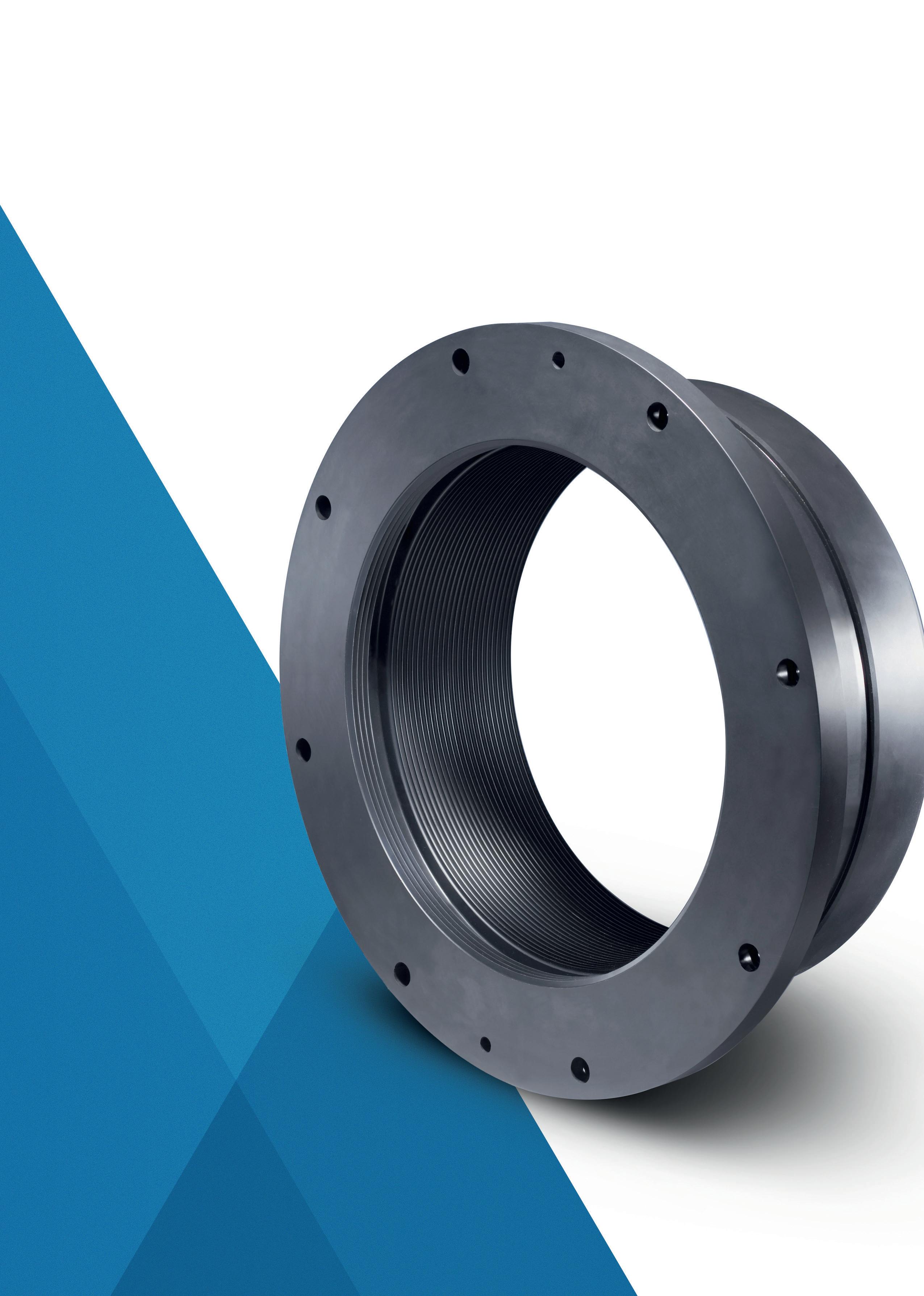
Arlon® 4020
Labyrinth Seal

Boosting Efficiency and Sustainability in Fertilizer Production with
22 Optimising water sustainability in ammonia production
08 Regional report: North America
Gordon Cope, Contributing Editor, discusses the challenges and opportunities facing North America’s fertilizer sector, including the impacts of geopolitical issues, environmental regulations, and new technologies.

13 Navigating the low-carbon ammonia journey
Deepak Shetty, Rolf Postma, and Nikolay Ketov, Stamicarbon, the Netherlands, explore how ammonia and fertilizer technologies, when integrated within an efficient low-carbon complex, can play a crucial role in supporting global efforts to reduce the nitrogen industry’s greenhouse gas (GHG) footprint.
17 The road to decarbonised ammonia
Matt Cousins, Johnson Matthey (JM), UK, and Klaus Nölker, thyssenkrupp Uhde, Germany, discuss the role that blue hydrogen can play in the decarbonisation of ammonia.

Giulia Sporchia and Elisa Brocca, Cannon Artes S.P.A., Italy, analyse solutions and technologies to effectively reduce the water footprint in ammonia production, through water recovery and reuse.
30 Advanced welding technology
Stefano Alberini, Belleli Energy CPE, Tosto Group, discusses the fabrication of a high-pressure ammonia synthesis converter with enhanced 2.25cr-1mo low alloy steel and advanced welding technology.
36 Q&A with Greene Tweed
Greg Gedney, Greene Tweed, considers how sealing solutions help to improve efficiency in the fertilizer industry.
38 Performance, purity, and phosphate processing
Kevin De Bois, Prayon, Belgium, explores advanced chemical benefication techniques within the phosphate processing industry.
43 Options for improvement
Ian K. Hancock, Bradley Pulverizer, UK, discusses classifier options for improved fertilizer milling.
49 Granulation in action
Alberto Militare, LB Technology, Italy, examines the benefits of fertilizer granulation within the agri-food, crop nutrition, and animal feed sectors.
53 Weighing up corrosion protection
Brad Hudson, Mettler Toledo, USA, outlines key considerations when designing vehicle scales to ensure adequate corrosion protection.
57 Advancing efficiency with AI
Brett Binnekade, Bagtech International, South Africa, discusses predictive maintenance with artificial intelligence (AI) in fertilizer blending and bagging plants, and how to make modern fertilizer plants more efficient and reliable.
61 Minimising the risk of dust-related explosions
Kyle Langley, Vortex Global, UK, considers methods to mitigate against the risks posed by dust accumulation.
65 Hot spot management
Johannes Poth, Integrated Global Services (IGS), Germany, explains how to manage the occurrence of hot spots in primary reformers at fertilizer plants.
69 The critical role of cooling
Igor Makarenko, Solex Thermal Science, Canada, explores the impact of thermal management on production and product quality.


Reduce stack emissions Decrease CAPEX Lowest cost construction Produce CO2free power Use of green ammonia/ hydrogen O2
IT’S THE SAME, BUT BETTER
Leveraging oxygen from water electrolysis / ammonia production, CORE-SO2™ technology decreases acid plants’ environmental footprint and greenhouse gas emissions while recovering clean energy and enhancing plant profitability.
• No fossil fuels required
• 98% lower emissions
• 60% less plot space
• 55% fewer contruction materials
• 50% decrease in CAPEX

MANAGING EDITOR
James Little james.little@palladianpublications.com
SENIOR EDITOR
Callum O’Reilly callum.oreilly@palladianpublications.com
ASSISTANT EDITOR Oliver Kleinschmidt oliver.kleinschmidt@palladianpublications.com
EDITORIAL ASSISTANT
Emilie Grant emilie.grant@palladianpublications.com
EDITORIAL ASSISTANT
Ellie Brosnan ellie.brosnan@palladianpublications.com
SALES DIRECTOR
Rod Hardy rod.hardy@palladianpublications.com
SALES MANAGER
Ryan Freeman ryan.freeman@palladianpublications.com
PRODUCTION
Iona MacLeod iona.macleod@palladianpublications.com
ADMINISTRATION MANAGER
Laura White laura.white@palladianpublications.com
HEAD OF EVENTS
Louise Cameron louise.cameron@palladianpublications.com
DIGITAL EVENTS COORDINATOR
Merili Jurivete merili.jurivete@palladianpublications.com
EVENTS COORDINATOR
Chloe Lelliott chloe.lelliott@palladianpublications.com
DIGITAL CONTENT ASSISTANT
Kristian Ilasko kristian.ilasko@palladianpublications.com
DIGITAL ADMINISTRATION
Nicole Harman-Smith nicole.harman-smith@palladianpublications.com
JUNIOR VIDEO ASSISTANT
Amelie Meury-Cashman amelie.meury-cashman@palladianpublications.com
Palladian Publications Ltd, 15 South Street, Farnham, Surrey GU9 7QU, UK Tel: +44 (0) 1252 718 999 Website: www.worldfertilizer.com
World Fertilizer Subscription rates: Annual subscription: £50 UK including postage £60 overseas (postage airmail) Two year discounted rate: £80 UK including postage £96 (postage airmail).
Subscription claims: Claims for non receipt of issues must be made within 3 months of publication of the issue or they will not be honoured without charge.
Applicable only to the USA & Canada: World Fertilizer (ISSN No: 2398-4384, USPS No: PENDING) is published 8 times a year by Palladian Publications Ltd GBR and distributed in the USA by Asendia USA, 701 Ashland Ave, Folcroft PA. Application to Mail at Periodicals Postage Prices is pending at Philadelphia, PA and additional mailing offices. POSTMASTER: send address changes to World Fertilizer, 701 Ashland Ave, Folcroft, PA. 19032.

The hot topic on everyone’s mind at the moment is tariffs. And this is no different for the global fertilizer industry, with market turmoil being perpetuated by the uncertainty regarding what lies ahead when it comes to new import taxes.1
The question is: how do we weather this storm?
The re-election of President Trump has caused a certain amount of volatility in many aspects of life, with impacts rippling out across the globe. These very ripples are now catalysing major changes, from pledging to help cease conflicts in regions such as the Middle East and Europe; to dramatic fluctuations in crypto-currency values after the announcement of the US crypto-currency reserve. It is clear to see that the impact is profound, and the fertilizer industry will also be impacted.
Import tariffs placed on Canada, Mexico, and China have culminated in uncertainty within the agricultural sector, primarily raising concerns over supply and demand issues – especially as the US relies on Canada for approximately 85% of its potash imports.2 But with the Trump Administration’s aim being to ‘make America rich again’, there is no surprise that tariffs have become an important pawn in this game of chess. The aim here is clearly to promote US industry whilst encouraging domestic agricultural activity.3 Not only this, but also to provide a greater standard of living for the American people, ensuring affordable food prices, access to fertilizers, and an overall strengthening of the country’s agricultural sector.
Proponents of autarky have advocated for national self-sufficiency in order to reduce the reliance on external factors for decades. This emphasised reliance on self-sufficiency is a theme gaining greater traction and prominence throughout the world, in an age where global tensions are running high and patience is running thin. COVID-19 exposed the weaknesses within the global supply chain, and, whether it is a ‘knee-jerk’ reaction or not, governments have ever since been re-evaluating their reliance on imports to sustain their demands economically, socially, and politically. This has therefore opened the door for the EU’s Open Strategic Autonomy policy – a policy placing emphasis on self-sufficiency without completely ruling out collaboration and cooperation where possible.4 A policy designed for the modern world.
Over the coming decade, it would be naïve to assume that the future of fertilizer imports, exports, production, and consumption will be plain sailing. The heightened buzz around trade barriers and restrictions has placed an ever-growing uncertainty within the sector; an uncertainty fuelled by market volatility. Not to mention the great strain being placed on the agriculture sector to provide the food to sustain the ever-growing population of the world. Despite this, however, it is important to remember that you can’t have a rainbow without a little rain.
This month’s issue of World Fertilizer Magazine features a North American regional report from contributing editor Gordon Cope, where he discusses the challenges and opportunities facing North America’s fertilizer sector, including the impacts of geopolitical issues, environmental regulations, and new technologies.
1. https://www.bbc.co.uk/news/articles/cgr21jjwg4wo
2. https://www.reuters.com/markets/us/us-farmers-face-higher-costs-fewer-markets-tariffs-farm-groupswarn-2025-03-04/
3. https://www.fertilizerdaily.com/20250306-trump-announces-tariffs-on-u-s-agricultural-imports-set-for-april-2/
4. https://www.europarl.europa.eu/thinktank/en/events/details/the-future-of-eu-s-open-strategicautono/20230215WKS04981
Agricultural producers on the Canadian Prairies stand to benefit from a collaboration between Arctic Gateway Group (AGG) and Genesis Fertilizers Ltd Partnership (Genesis Fertilizers), which is focussed on cutting fertilizer import and export costs, improving supply chain reliability, and expanding market reach.
The parties have entered into a letter of intent to establish a framework for cooperation between AGG and Genesis Fertilizers to enhance business opportunities and facilitate the development of efficient logistical and supply chain solutions. The parties seek mutually beneficial new import and export shipments in 2025 and beyond.
Genesis Fertilizers and AGG will cooperate to source and import phosphate and ammonium sulfate supply from international vendors as feedstock for the products to be produced at Genesis Fertilizers’ proposed nitrogen fertilizers facility to be built at Belle Plaine, Saskatchewan. The parties seek to distribute such supply domestically through facilities at the Port of Churchill and the planned SuperCenter distribution network of Genesis Fertilizers. Currently, this feedstock is brought into Canada from the US by other importers.
In addition, AGG aims to utilise Genesis Fertilizers’ transportation and storage needs to expand its logistical capabilities and grow their operations. By collaborating on best practices for storage, shipping, distribution, and supply chain management, AGG aims to create operational efficiencies that will benefit both organisations. This collaboration is expected to increase shipping and rail traffic, optimise the use of AGG’s rebuilt infrastructure, and establish a strong new relationship with a key player in the Canadian fertilizer industry. Both companies are also committed to increasing jobs and training for Indigenous and northern communities through this increased economic activity.
Genesis Fertilizers seeks to leverage AGG’s port and rail infrastructure to efficiently link its fertilizer products to key markets, reducing lead times and costs. By tapping into new and emerging markets that AGG’s network provides access to, Genesis Fertilizers aims to enhance the growth potential for the plant’s production. The collaboration with AGG will also foster timely delivery and optimised supply chains for fertilizer distribution to both domestic and international markets. This collaboration underscores the benefits of farm producers partnering with northern communities and Indigenous groups to strengthen Canada’s agricultural resilience. By fostering these relationships, producers can contribute to a more stable and sustainable food supply chain, ensuring long-term benefits for all Canadians.
IRELAND OMEX opens Ireland’s largest liquid fertilizer facility
OMEX Ireland has officially opened the country’s first and largest dedicated liquid fertilizer distribution hub at the Port of Cork. This landmark facility marks a major milestone for Irish agriculture, ensuring farmers across the country have reliable access to high-quality liquid fertilizer.
With a significant storage capacity, the Cork terminal is the largest of its kind in Ireland and is strategically positioned to serve all key agricultural regions. The facility utilises fertilizer technology, operating 24/7 to supply high-performance liquid N+S fertilizers. OMEX’s investment into liquid fertilizer infrastructure offers Irish farmers a dependable and efficient nutrient management solution
The facility was officially inaugurated on 5 March 2025, with key representatives from OMEX, including Chairman Max Winkler and Managing Director Sam Bell. Leading figures from the Irish farming community also attended, recognising the significance of this investment for the sector.

Sulphur World Symposium 2025 08 - 10 April 2025 Florence, Italy www.sulphurinstitute.org/ symposium-2025/
The Fertilizer Show 08 - 10 April 2025 Orlando, Florida, USA www.fertilizershow.com
IFA Annual Conference 12 - 14 May 2025 Monaco www.IFA2025.org
48th Annual International Phosphate Fertilizer & Sulfuric Acid Technology Conference 06 - 07 June 2025
St. Petersburg Beach, Florida, USA aiche-cf.org/annual-conference
99th Annual Southwestern Fertilizer Conference 13 - 17 July 2025 Nashville, Tennessee, USA www.swfertilizer.org
69th Annual Safety in Ammonia Plants and Related Facilities Symposium 7 - 11 September 2025 Atlanta, Georgia, USA www.aiche.org/conferences/ annual-safety-ammonia-plants-andrelated-facilities-symposium/2025
ANNA 2025
12 - 17 October 2025
Omaha, Nebraska, USA www.annawebsite.squarespace. com/2025-conference
Wood Mackenzie Hydrogen Conference 12 - 13 November 2025
London, UK www.woodmac.com/events/ hydrogen-conference
POLAND Grupa Azoty comments on the current situation in the fertilizer market
For several weeks now, fertilizer prices have been on an upward trend in the main global markets. This is the result of several factors – demand, fertilizer availability, and supply logistics. Fertilizers are becoming moderately more expensive both in countries with low and stable production costs and in countries where costs are high and subject to rapid changes. In light of the trend observed over several quarters of postponing fertilizer purchases until just before the seasonal peak, Grupa Azoty consistently recommends spreading purchases over several batches to reduce the risk of buying products at high prices.
Since the beginning of the year, urea prices in the Baltic have increased by US$85/t (approximately 340 PLN/t). Prices of nitrate fertilizers (AN, CAN) at major European producers have also risen by about €60/t (around 250 PLN/t) during the same period.
Although natural gas prices at around €45/MWh are slightly lower than at the beginning of March 2025, they remain high in the context of fertilizer production costs. It should be noted that compared to prices a year ago, they are as much as 50% higher – before the war in Ukraine, they were between €15 - 20/MWh. The rapid fluctuations in gas prices cause producers to continuously adjust fertilizer prices according to the current raw material situation.
3Degrees has launched the Low Carbon Fertilizer Alliance, a collaborative initiative designed to help reduce emissions in agricultural supply chains.
Managed by 3Degrees, the alliance leverages decades of expertise in greenhouse gas (GHG) strategy and agricultural emissions reductions by bringing together organisations in the food, beverage, and apparel industries. The alliance is supported by founding member Mars Inc., alongside three additional Fortune 200 food companies, with CF Industries joining as the founding manufacturing member.
The alliance provides a scalable approach to decarbonising fertilizer manufacturing by funding emissions reduction initiatives within the agriculture value chain. With funding to be secured through the alliance, CF Industries has committed to complete a new nitric acid plant emissions abatement project at its Verdigri manufacturing facility in Oklahoma, US, which is expected to reduce CO2 emissions from the facility by 600 000 tpy, beginning in 2025.
ANGOLA Minbos receives second tranche of funds from FSDEA for 2025 field
Minbos Resources Ltd (Minbos) has announced that it has received the second tranche of funding, totalling US$2.43 million, from the Fundo Soberano de Angola (FSDEA).
The final tranche of funding, totalling US$1.17 million, will be completed upon the company finalising the renewal of project insurances and presenting supplier quotations for project long lead items to FSDEA.
The company’s early trials in Angola in 2025 continue to perform strongly. Take aways from the trials include: improved crop yields with PRIMEIRO, particularly in areas with low soil phosphorus and low pH (acidic) soils; PRIMEIRO has demonstrated yield increases by up to 80% when applied as the only source of phosphorus; and that local trials have shown that without phosphorus, other nutrients are not effective.


Gordon Cope, Contributing Editor, discusses the challenges and opportunities facing North America's fertilizer sector, including the impacts of geopolitical issues, environmental regulations, and new technologies.
North America is a leading producer of food and fertilizer for both domestic consumption and export. However, a variety of challenges within the US and Canada, as well as around the world, have the capacity to whipsaw the sector in dramatic fashion; drought, wars, environmental goals, trade disputes and geopolitics, to name a few.
Since May 2024, phosphate Gulf spot prices have surged 10%, to above US$575/t. The primary reason is China, which churns out over 17 million tpy. Once the world’s leading exporter of phosphate fertilizer, the country has taken various steps since 2021 to limit fertilizer exports in order to protect its domestic market and encourage food production. In June 2024, it extended export bans on urea and phosphate, slowing the former and virtually eliminating the latter.
North America produces approximately 7 million tpy of phosphate fertilizer and imports over 2.7 million tpy, primarily from Morocco, to meet its agricultural needs. Florida accounted for over half of all phosphate ore production, but producers in the tourism-reliant 'sunshine state' are facing increasing regulations and fines associated with groundwater contamination, wastewater spillage, waste piles, and red tide blooms spoiling pristine beaches.
North American producers are seeking new sources of phosphates. In Quebec, First Phosphate continues to advance its discovery at the Bégin-Lamarche project located in the region of Saguenay-Lac-St-Jean. In June 2024, it announced that drilling had delineated 41 million t of recoverable ore using open pit mining. Testing has indicated levels of phosphorus pentoxide (P2O5) as high as 39.45%; at this purity, the mineral qualifies as direct shipping ore (DSO). Samples are devoid of high concentrations of harmful elements such as cadmium, facilitating preparation.
Vancouver-based Fertoz Ltd has staked some of the largest sedimentary deposits of phosphate in Canada.
The Wapiti project in northeast British Columbia contains approximately 1.4 million t of +20% P2O5 phosphate rock at a depth of less than 30 m. The company is currently seeking industrial minerals mining permits to conduct up to 250 000 t of sampling in order to determine its viability in both fertilizer and lithium-iron-phosphate battery applications.
The US and Canada produce over 15 million t of potash fertilizers annually, with abundant room for capacity growth. International sanctions imposed against Belarus and repercussions against Russia after its invasion of Ukraine have significantly impacted potash exports from the two countries;
Russia’s output dropped 45%, to approximately 5 million tpy, and Belarus over 60%, to approximately 3 million tpy.
North American producers responded to the shortfall. Nutrien, based in Calgary, Canada, and the world’s largest potash producer, upped production from an initial 14 million tpy to almost 15 million tpy by the end of 2022. Rising prices reduced applications, however, leading to unsold inventory. Lower prices induced a rebound, however, and Nutrien now forecasts that full-year shipments for 2025 will reach 71 - 74 million t, up from the 2024 estimate of 70 - 72 million t, as growers around the world replenish soil nutrients.1
In April 2024, BHP reported that stage one of its new Jansen mine in Saskatchewan, Canada, is 44% complete, and is on track to begin production in 2026. The CA$5.4 billion underground mine will have a capacity of 4.5 million tpy. They have also approved CA$4.9 billion for stage two, which will double output capacity to 8.5 million tpy when it comes on stream in 2029. Further stages could see production eventually rise to 16 - 17 million t.
North America is a major producer of nitrogen fertilizer, with approximately 16 million t of various liquid and solid products produced annually.
The health of the North American nitrogen fertilizer sector is closely linked to the fortunes of domestic farming. Over the last several years, droughts have caused regional crop failures, high prices have deterred applications, and cereal prices have experienced volatility. In its 3Q24 report, Nutrien noted that, while crop prices have reduced margins to farmers, near record yields in corn and soybeans have bolstered incomes and the majority of growers in the US Midwest are in sound financial standing to replenish soil nutrients.
The strength of the farm sector is encouraging producers to expand capacity. According to a GlobalData report, North America is expected to dominate global ammonia capacity additions for the next five years.2 Currently, world capacity stands at slightly over 240 million tpy, with 71 million tpy expected to be added by 2028. North America is the leading region for new capacity, with 29 million tpy planned. The list includes:
n Ascension US$7.5 billion Clean Energy Donaldsonville, (Louisiana, US) ammonia plant, with an ultimate capacity of 7.2 million tpy of blue ammonia, expected to enter service in 2029.
n St Charles Clean Fuels US$4.6 billion St. James Parish (Louisiana, US) plant, which will have a capacity of 2.9 million tpy, is expected to enter production in 2027.
n CF and Mitsui’s US$2 billion Ascension Paris (Louisiana, US) plant, expected to produce 1.5 million short tpy of blue ammonia when it opens in 2027.
The predominance of new ammonia capacity being built in North America has several causes. Prices for natural gas, used as both feedstock and processing energy, are lower than most other jurisdictions in Asia and Europe for instance, but the US is also on a crusade to shift to low-carbon hydrogen. Not only does the energy-dense element produce nothing but water when burned, it can also be manufactured anywhere using electrolysis powered by wind and sun, reducing geopolitical risk.
Producing clean-burning hydrogen fuel is creating immense opportunities for nitrogen manufacturers. Because transporting and burning hydrogen itself is rather costly and complex, a much easier method is to convert the gas into liquid ammonia, which can then be consumed in internal combustion engines (ICEs) with minor alterations.
The maritime sector is expected to lead the conversion to ammonia fuel. Rystad Energy, a consultancy, predicts that total exported volumes to surge from around current levels of 19 million tpy (most of which is used in fertilizer products), to 76 million tpy by 2035 (most of which will be transport and utility fuel related). By 2050, that figure could be over 120 million tpy.3
North America is expected to play a key role. Under the Biden Administration’s Inflation Reduction Act, the federal government could provide up to US$3/kg in subsidies for clean hydrogen.
In September 2024, Netherlands-based OCI announced the sale of its blue ammonia production facility in Beaumont, Texas, US, to Australia’s Woodside Energy, for US$2.35 billion. OCI and Linde are currently building the 1.1 million tpy plant; when it enters production in 2025, Linde will use carbon capture and sequestration to supply blue hydrogen and nitrogen feedstock. A second train of equal capacity is seeking regulatory approval.
German-based RWE, LOTTE Chemical of Korea, and Japan’s Mitsubishi continue to develop plans to build a clean ammonia production and export facility in the port of Corpus Christi, Texas, US. The complex would be built in phases, with a final capacity approaching 10 million tpy by 2030. Blue and green ammonia would be exported to Asia and Europe for use as both fuel and a source of renewable hydrogen.
Not all projects are facing smooth sailing, however. Yara, based in Norway, is planning to build a blue ammonia plant with Enbridge, a major North American pipeline company, in Ingleside, Texas, US. The unusual joint venture was announced in 2023 when the two partners realised that their respective assets and goals would optimise the joint project. Over the last several years, Enbridge has been expanding the Enbridge Ingleside Energy Center (EIEC), a massive terminal located in Corpus Christi, Texas, US, on the Gulf of Mexico. Project YaREN would include two trains with a total capacity of 2.8 million tpy of output, starting in 2028. The project faces strenuous objections from the communities in Ingleside, however; residents are concerned about potential ammonia leaks and the lack of emergency planning.
Several projects have also hit financial roadblocks. In November 2024, Air Products announced that it was cancelling its proposed US$4.5 billion green hydrogen plant with partner AES Corp. The 1.4 GW plant, to be built in Wilbarger County, Texas, US, was to be the largest green hydrogen plant in the US, producing 200 tpd. Air Products, which is building the immense green hydrogen plant at Saudi Arabia’s NEOM project, decided to back out of the deal due to poor demand.
Air Products is following in the footsteps of Nutrien. In early 2023, the company announced plans to build the world’s largest blue ammonia facility at its existing complex in Geismar, Louisiana, US. The 1.2 million tpy plant would permanently remove up to 90% of CO2 emissions using


carbon capture and sequestration (CCS) technology. Later that year, Nutrien placed the project on hold, citing increased building costs and uncertainty over the premium market for clean ammonia.
The Canadian federal government wants to reduce carbon emissions in all sectors by 45% by 2030, primarily through carbon taxes and restrictive legislation. Currently the carbon tax stands at CA$80/t of CO2e, and is scheduled to climb by CA$15/tpy to CA$170 by 2030. Grain farmers use large amounts of natural gas to dry and maintain stored grain, however, and greenhouses use natural gas and propane to maintain operations through the winter months. In addition, Ottawa, Canada, is pondering fertilizer restrictions. The latter, especially, has the sector concerned.
In the US, the election of President Donald Trump will have significant impact on the agricultural sector for three primary reasons. First, environmental legislation – a foundation of the Biden Administration – is expected to take a back seat for the next four years. While this may supply relief to farmers wrestling with higher energy bills, others could experience significant drops in income. The Conservation Reserve Program (CRP) was created by the United States Department of Agriculture (USDA) in 1985 to encourage land owners to set aside environmentally sensitive land, primarily near waterways and marshes. The intent was to create buffers that would encourage wildlife and pollinators to thrive. Today, the programme delivers US$2 billion to farmers to conserve over 25 million acres of land. According to Project 25, a political playbook written by conservative supporters of President Trump, the CRP would be eliminated.
Secondly, the first Trump Administration generated a trade war with China that had far-reaching impacts on farming; a 20% tariff caused a loss of US$23 billion in sales of soy and corn to China. During his recent campaign, President Trump threatened a 60% blanket tariff that could have a far greater impact. In order to placate producers during the first trade war, President Trump allocated over US$20 billion to the farming sector, but there are no guarantees that any future losses would be covered. In addition, China has made significant strides to increase domestic food consumption and deepen trade relations with Brazil, which now delivers US$60 billion of food to China annually. The Asian country could also impose its own 60% tariff on US goods, crippling corn and soy exports.
Finally, the 2018 - 2023 Farm Bill, which expired on 1 October 2023 (and has been extended through several temporary measures), must be formally renewed by Congress in 2025. The massive omnibus bill directs US$1.5 trillion per decade to food and agriculture. The majority is targeted to the USDA's main food-aid programme, the Supplemental Nutrition Assistance Program (SNAP). The remainder funds a host of farm-aid programmes, generally referred to as the farm safety net. Republicans favour farm aid, while Democrats prioritise help to the poor. Project 25 proposes eliminating major portions of the bill, but Republicans are fully aware that the small number of agribusinesses that control the immense land, meat processing, and cereal exports benefit immensely from the bill. And farmers vote.
Fertilizer production has a significant impact on the environment. Ammonia producers emit an estimated 1.3% of all greenhouse gases (GHGs) per year, primarily from the use of coal and natural gas as both feedstock and energy. While blue and green ammonia initiatives are helping to reduce GHG intensity per t, it will be a costly challenge to meet net zero targets by 2050.
A recent study shows that runoff of phosphorous fertilizer from farms has increased over the last four decades. Researchers at Pennsylvania State University analysed data from 430 rivers across the US from 1980 to 2019. The loss leads to pollution in drinking water and algal blooms that deprive fish of oxygen. Although efforts have been made to reduce urban sources of phosphorous, such as waste treatment plants, extreme weather events dumping large amounts of rain on agricultural lands increase runoff losses. In response, Pennsylvania State University alumni have developed a phosphate granule that is activated by plant roots, increasing uptake efficiency by 50% and reducing runoff while maintaining yields.
In order to reduce emissions, BHP has opted to use underground battery-electric loaders for its Jansen Potash Project in Saskatchewan, Canada. Sandvik will provide ten vehicles for the first phase of the project. BHP touts that the mine will have the lowest carbon footprint of any potash mine operating in Saskatchewan.
In February 2025, President Trump imposed a 25% tariff on a wide range of Canadian goods. US farmers rely on Canada for almost 90% of their potash needs, and fear that the tariffs could add up to US$75 per short t, reducing profit margins and potential yields.
In the coming decade, demand for nitrogen, potash and phosphate fertilizer is expected to remain healthy due to a growing world population and a shift of diets toward animal protein. Net zero environmental regulations are also expected to create demand for millions of tonnes of green ammonia for use in marine transport. The trade barriers restricting Belarusian and Russian potash exports will act as an incentive to develop the immense potash reserves in Canada that present large-scale, low-cost expansion opportunities. New sources of phosphorous throughout North America will gradually displace Moroccan imports.
North America’s fertilizer producers have adapted well to recent challenges; being isolated from the regional turmoil in Eastern Europe and the Middle East, for instance, has encouraged investment in the low-risk continent. While volatility in international trade of fertilizer is unlikely to abate in the near-term, long-term trends in the food commodities market and the opportunities presented by new uses of ammonia will create significant prospects for growth in the coming decade.
1. https://www.nutrien.com/news/press-releases/nutrien-reports-thirdquarter-2024-results-1713.
2. https://www.globaldata.com/store/report/ammonia-marketanalysis/?_gl=1*iri4vo*_ga*MTAzOTgwMDI2Ni4xNzMyMjE1MTE1*_ga_ TDKVNS5N2K*MTczMjIxNTExNS4xLjEuMTczMjIxNTE4NC42MC4wLjA.
3. https://www.rystadenergy.com/news/hydrogen-exports-shiftammonia-production-2035.

Deepak Shetty, Rolf Postma, and Nikolay Ketov, Stamicarbon, the Netherlands, explore how ammonia and fertilizer technologies, when integrated within an efficient low-carbon complex, can play a crucial role in supporting global efforts to reduce the nitrogen industry’s greenhouse gas (GHG) footprint.
The global nitrogen industry is a cornerstone of food production through fertilizers. It is also expected to play an increasingly important role in other applications, from energy to industrial processes. However, it is also a major contributor to greenhouse gas (GHG) emissions, making the reduction of its carbon footprint a critical priority.
This challenge can be tackled by adopting highly efficient industrial processes, maximising efficiency through the integration of industry-leading technologies, and minimising emissions with advanced solutions to create value chains rooted in circularity, stewardship, and responsible resource use. A reduced-carbon emissions ammonia plant has the potential to revolutionise the industry, reshaping how global food security and energy demands are met.
Companies, such as Stamicarbon, the nitrogen technology licensor of NEXTCHEM (MAIRE Group), are assisting in this transition, creating ammonia and fertilizer technologies for a more sustainable future.
Developed over a century ago, the Haber-Bosch process remains the cornerstone of the ammonia industry. While this method can use hydrogen from any source, today's dominant production method uses hydrogen coming from fossil fuels. This is typically done through steam reforming of natural gas or coal gasification, leading to significant carbon emissions, resulting in the product ammonia referred to as ‘grey’.
Efforts to make this conventional ammonia production process more sustainable led to the development of ‘blue’ ammonia. In this method, the carbon dioxide, previously emitted into the atmosphere, is captured and stored, or utilised in other processes.
Green ammonia is produced by using renewable electricity to power electrolysers, which split water to create hydrogen and oxygen. The nitrogen needed for ammonia synthesis is obtained from the air using a nitrogen generation unit. This method enables the production of ammonia with minimal GHG emissions, positioning it as one of the most promising approaches for a low-carbon future.
While there are other ‘colours’ of ammonia, recent industry discussions have primarily focused on the actual carbon reduction rather than the source of feedstock.
While the availability of electrolysers and the cost of renewable electricity remain key challenges for gigawatt-scale projects, smaller ammonia plants offer a viable pathway for early adopters to achieve their decarbonisation goals. Modular and scalable green ammonia production, suitable for local production of urea, nitrates, diesel exhaust fluid (DEF), or ammonia to be used as fuel, offers a promising pathway.
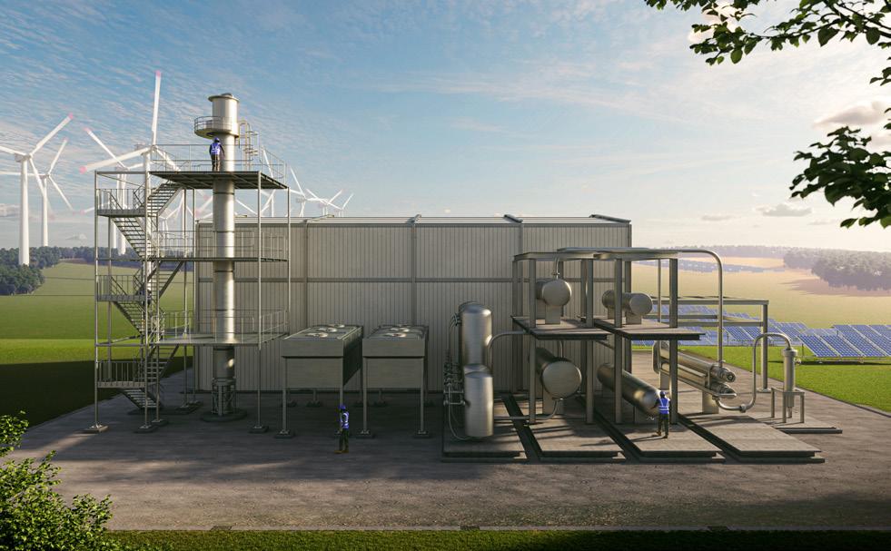
Stamicarbon’s NX STAMI AmmoniaTM technology (Figure 1), designed for small- to medium-sized plants (50 - 500 tpd), enables ammonia production from renewable energy with minimal environmental impact. This high-pressure technology optimises efficiency of a conventional process while maintaining a compact and cost-effective design.
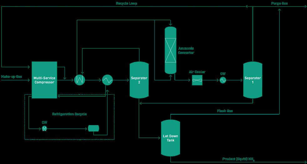
The ammonia synthesis loop operates at a high pressure (~300 bar), increasing conversion efficiency while reducing the need for costly refrigeration systems. The process flow (Figure 2) begins with make-up gas, a mixture of hydrogen and nitrogen from an upstream electrolyser and nitrogen generation unit. This gas is compressed in an electrical-driven reciprocating compressor to over 300 bar, with the recycle stream also recompressed to the same pressure.
The ammonia converter used in this process features a single axial flow catalyst bed design. Heat exchange tubes submerged in the catalyst bed allow for better temperature control, preventing adverse effects such as catalyst sintering. Simultaneously, the converter feed is preheated using the exothermic reaction heat. An integrated start-up heater is also included within the converter.
The high-pressure synthesis loop allows for single-stage ammonia condensation using cooling water, eliminating the need for a refrigeration compressor. This reduces equipment count and achieves 25 - 30% capital expenditure (CAPEX) savings. Over 85% of ammonia is recovered in separator 1, while additional uncondensed ammonia is captured in separator 2.
Ammonia can be produced at a pressurised condition (i.e., 16 - 18 bar) and ambient temperature to be stored in bullets or used in downstream plants, or any intermediate pressure level as required, such as 8 bar required for shipping. Alternatively, the final product can be at ambient pressure and -33°C to be stored in atmospheric ammonia storage.
While the high-pressure ammonia loop offers advantages for small- to medium-scale production, the demand for

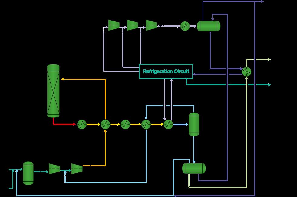
low-cost and high-efficiency ammonia production is leading to the development of conventional larger-scale ammonia plants. Stamicarbon offers the medium-pressure technology, designed for capacities from 50 to 3500 tpd, with potential for even larger capacities, depending on customer’s needs.
This medium-pressure ammonia technology (Figure 3) features a multi-bed, radial-flow reactor with a low-pressure drop configuration. This has been optimised to allow high per pass conversion with the minimum possible catalyst volume and can be customised based on operating variables.
The system is notable for its superior temperature control in the first bed, allowing for a more efficient converter operation and a longer expected catalyst lifespan.
With over 45 industrial references, this process offers a cost-effective and proven ammonia production solution.
As the demand for low-carbon ammonia increases, fertilizer producers must adopt advanced technologies to achieve significant emission reductions. While conventional ammonia production allows for only incremental CO2 reductions, significant cuts can only be achieved through carbon capture, utilisation, and storage (CCUS).
Fortunately, auto-thermal reforming (ATR) provides a solution for large-scale blue ammonia production, as it generates a highly concentrated CO2 stream that makes CCUS both technically feasible and, under the right conditions, economically attractive.
ATR is a highly efficient process that maximises ammonia production while minimising external energy requirements. ATR is particularly advantageous for production of blue ammonia (and, equally, blue hydrogen and low-carbon methanol) as it provides a highly concentrated CO2 stream, enabling carbon capture rates of up to 95%. ATR presents a viable alternative for world-scale low-carbon ammonia production. NEXTCHEM’s ATR process operates at high pressure (70 bar), which reduces compressor duty in the ammonia plant, lowering operational expenditure (OPEX). Robust, proven equipment, a flexible feedstock intake, and higher energy efficiency due to a simplified process scheme result in lower CAPEX and OPEX.
By making carbon capture more feasible, ATR enables the production of low-carbon ammonia, which can be
integrated into a world-scale fertilizer complex or supplied as a low-carbon fuel or energy carrier.
Using low-carbon ammonia directly in urea production can significantly reduce the carbon emissions associated with nitrogen-based fertilizers. Alternatively, nitrate-based fertilizers can offer even greater GHG reduction potential, making them an attractive solution for sustainable agriculture in the right conditions.
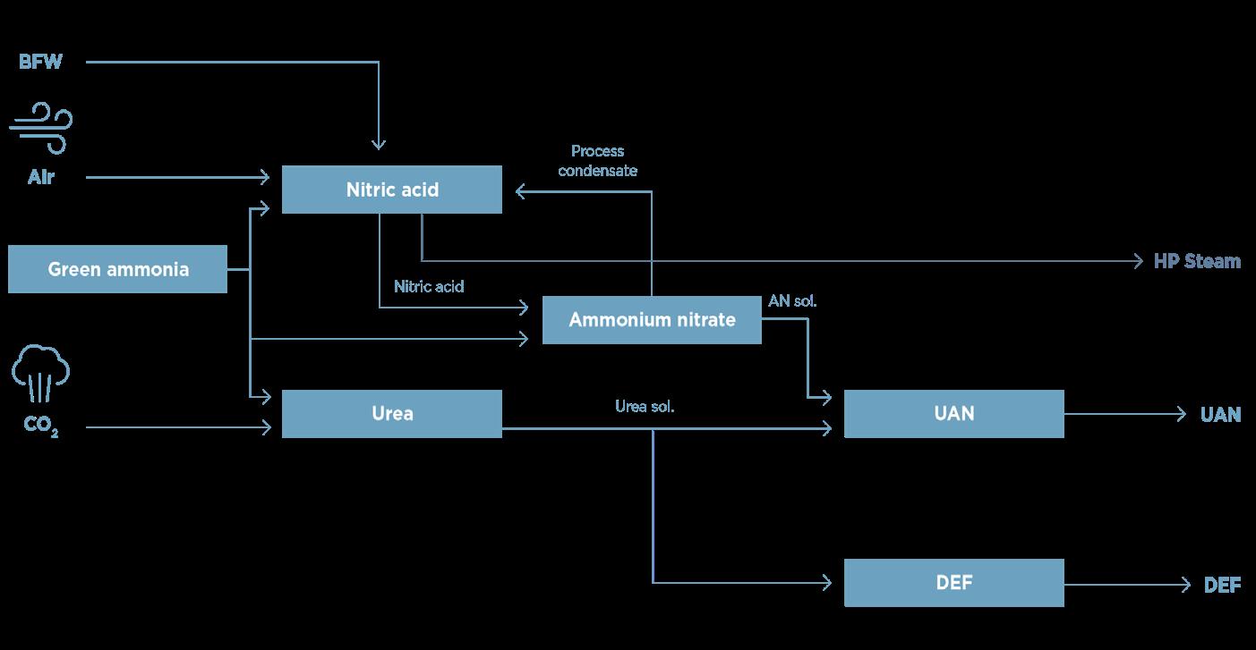
A low-carbon fertilizer plant, as shown in Figure 4, can integrate multiple units, including ammonia, urea melt, nitric acid, ammonium nitrate solution, DEF, and urea ammonium nitrate (UAN). An integrated complex, incorporating ammonia loop, can be delivered by a single licensor.
An example of integrating the company’s technologies is the Meadowlark Project in Gothenburg, Nebraska, US. This facility will be the first to combine the technologies in ammonia, urea, ammonium nitrate, UAN, nitric acid, and DEF.
Powered entirely by renewable energy, this plant will produce 450 tpd of green ammonia. Down the line, the nitric acid plant will have a nameplate capacity of 330 tpd and will be integrated with a urea melt plant, ammonium nitrate neutralisation section, and UAN mixing section. The facility is projected to produce impressive outputs: 365 000 t of UAN, 146 000 t of ammonium thiosulphate (ATS), and 20 million gal./yr of DEF. This project represents a fully integrated green fertilizer plant that will supply fertilizers for the local farmers while utilising waste CO 2.
Another example of the integration of the technologies is the FertigHy project in France. NEXTCHEM has been awarded a feasibility study and pre-FEED contract for FertigHy’s first low-carbon fertilizer plant. The plant, expected to start construction in 2027, will produce 500 000 t of low-carbon nitrogen-based fertilizers annually, using hydrogen from renewable and low-carbon electricity. The company’s technologies will enable environmentally friendly ammonia production and highly efficient nitric acid processing with minimal GHG emissions.
The availability of various process designs tailored for different feedstock and scales is enabling economically viable, low-carbon integrated plants. Stamicarbon’s technology enables ammonia production using renewable energy or fossil fuels with minimal environmental impact, while the NEXTCHEM’s ATR process maximises ammonia production and efficiently integrates with CCUS. These technologies provide a comprehensive approach to low-carbon fertilizer and fuel production in a lean, highly efficient plant.

Matt Cousins, Johnson Matthey (JM), UK, and Klaus Nölker, thyssenkrupp Uhde, Germany, discuss the role that blue hydrogen can play in the decarbonisation of ammonia.
There is an urgent need to limit the rise in global temperatures to avoid severe environmental and societal impact. Many countries across the world have committed to zero emission targets being met by 2050, this timeframe is now only one typical syngas plant lifetime away. The provision of decarbonised hydrogen at scale is an essential step to achieve this. It is forecasted that ammonia production will increase threefold by 2050. At present, around 85% of ammonia production is used to manufacture nitrogen fertilizers, with the remainder used in applications such as refrigeration, mining, pharmaceuticals, water treatment, plastics, fibres, and the abatement of nitrogen oxides (NO x).
New applications including the use of ammonia as a low carbon fuel in the maritime sector, for stationary power generation or as a hydrogen carrier are emerging, and fast-growing markets require decarbonised ammonia.
Ammonia production is a highly energy-intensive process, which currently accounts for about 2% of global energy consumption. Global production was nearly 180 million t in 2022, with associated CO 2 emissions of 420 million t CO 2 1 The challenge facing the ammonia industry is twofold – how to achieve a step change increase to overall ammonia production without increasing overall CO 2 emissions; and how to decrease the CO 2 intensity of existing ammonia manufacturing assets.
Low carbon ammonia can be either produced via:
n Renewable energy with electrolytic hydrogen.
n By combining conventional fossil-fuels processes with carbon capture.
To achieve climate targets and lower carbon emissions that occur through ammonia production, we need both methods to produce affordable and efficient low carbon ammonia. This article discusses the role of blue hydrogen in decarbonising ammonia.
Blue ammonia production projects can be executed today using well proven technology. These will provide a chemical feedstock that is already transported and used extensively around the world, offering a carbon-free molecule, with a low carbon intensity for use as an energy vector. Current ammonia and fertilizer producers, with decades of experience in ammonia production, can support meeting this need, through applying their know-how and ammonia infrastructure to operate future low carbon ammonia flowsheets.
By reforming natural gas with carbon capture and storage (CCS) to produce low carbon (blue) hydrogen, one can efficiently convert this into low carbon ammonia (NH 3) via the Haber Bosch process, with significantly reduced carbon emissions. The announcement of the JM and uhde® decarbonised ammonia – where the companies integrate JM’s LCH TM technology with uhde® ammonia process –offers a way to do this at scale today.
Low carbon hydrogen can be produced via two primary routes:
n Electrolytic splitting of water using renewable electricity.
n Reforming of fossil resources with CCS.
Hydrogen produced from renewable resources is commonly referred to as ‘green hydrogen’, from fossil resources with CCS as ‘blue hydrogen’, and from fossil resources without CCS as ‘grey hydrogen’.
Arguably the best way to achieve the scale up of hydrogen production is to be technology agnostic –embracing both blue hydrogen and green hydrogen production to ensure growing demand can be met quickly and sustainably.
Greening the production of electricity will play a crucial role in decarbonising our energy mix. Using this resource, we should continue to increase green hydrogen production. We should also recognise that the greener power can support production of lower carbon intensity blue hydrogen and ammonia. As greener power is imported into a blue ammonia process, it also has a positive effect. It is encouraging to see ongoing investment and more renewable electricity capacity added to our energy system, as this will help bring the overall cost of clean hydrogen down.
To put the scale of the energy transition into context on a global basis, replacing all fossil fuel derived hydrogen with green hydrogen would require all the solar and wind power generation capacity currently in operation and developing. As already set out, much more hydrogen will be required to meet demand as new uses for hydrogen come online. This is where blue hydrogen should complement green hydrogen. It is ready to scale up now
and can meet our immediate needs to reduce CO 2 emissions, while green hydrogen will take longer to scale.
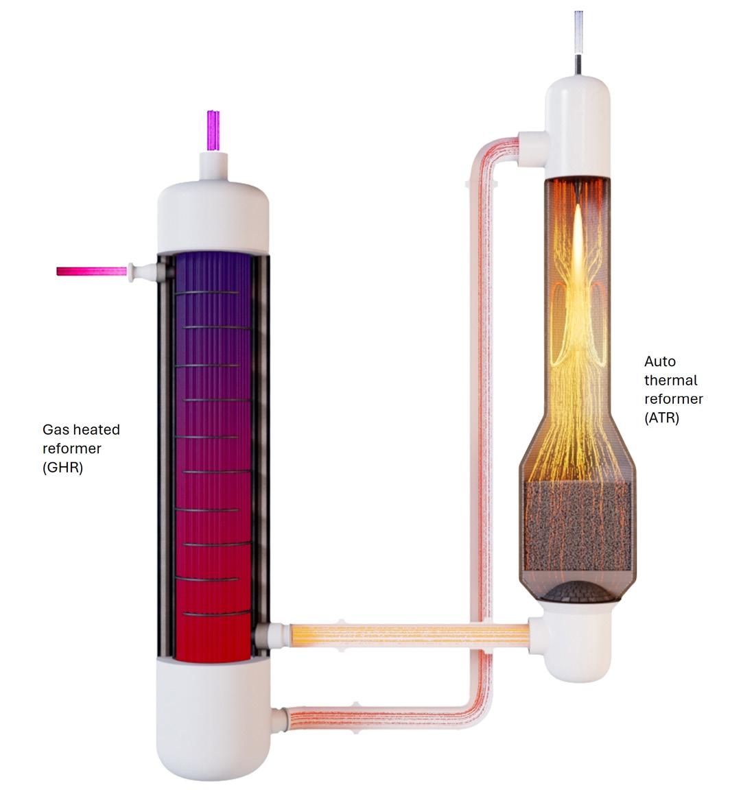
Steam methane reforming and advanced gas reforming are the two principal technologies used for blue hydrogen production. Advanced gas reforming consists of either an autothermal reformer (ATR), or an ATR coupled with a gas heated reformer (GHR). Where there is a requirement to capture CO 2, it is recognised that advanced gas reforming is a more appropriate technology for generation of blue hydrogen, due to its provision of a more suitable stream for CO 2 capture. JM's LCH technology enables decarbonised hydrogen to be produced at scale now, in a sustainable manner.
The ATR flowsheet combines two processes that take place in a primary reformer:
n Heating of the process gas.
n Reforming of the feedstock.
The ATR flowsheet carries out both these functions on the process side of the flowsheet, meaning there is no low-pressure atmospheric CO 2 release (Figure 1).
It does this by introducing oxygen through a burner, which entrains the oxygen flow with the process gas.
This happens in the area directly below the burner. Simultaneously the gas stream ignites due to the flammability of the gas mixture, and it is partially oxidised (burnt) creating heat, resulting in the formation of CO x and water (H 2 O).
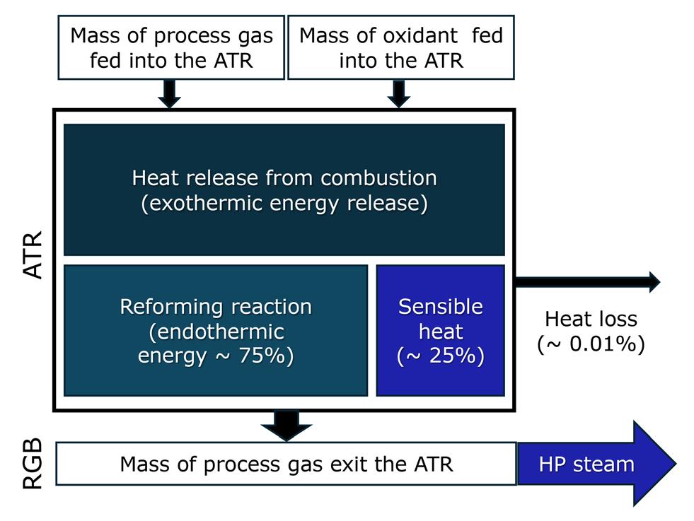
The adiabatic ATR reactor is energy balanced, considering energy from combustion, and energy consumed by the endothermic reforming reaction and energy loss from the vessel. The net difference is the sensible heat energy. The process gas exits the ATR and then passes through a reformed gas boiler where a portion of sensible heat can be used to raise steam. This energy balance is illustrated in Figure 2.
Steam raising from the ATR is necessary (and as such involuntary) for its operation. However, it has a positive effect on the energy balance of the overall flow sheet, providing energy to drive machines. However, raising additional steam requires burning more feedstock in oxygen (O 2 ). So, the focus should be to optimise where the operating conditions allow for long stable operating cycles of at least 4 years.
The hot, well mixed gas stream now passes through a catalyst bed. It is through this bed that the reforming reactions take place, producing hydrogen by reacting process gas with steam as shown by the general reaction equations below. While the CO also reacts with H 2 O in the process, to produce hydrogen (H 2 ), and CO 2 via the water gas shift process.
General steam methane reforming reaction:
Water gas shift (WGS) reaction:
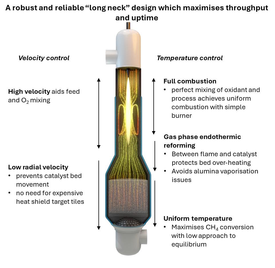
The equilibrium position and kinetics favour high methane conversion at the typical ATR exit temperature (950°C - 1050°C). The ‘long-neck design’ can enable long runs and high effectiveness from relatively small volumes of catalysts.
The ATR operation should be considered in the context of the hydrogen (or ammonia) flowsheet it is part of. In either case the target product contains no carbon. Part of the optimisation for a process that does not benefit from CO as a downstream reactant should maximise hydrogen production from reforming and WGS. By doing this, we maximise the amount of hydrogen generated from splitting water in the process. So, the choice of operating conditions; (i) temperature, effected by level of combustion, and (ii) the ratio of steam to carbon (S:C), should reflect this target.
O 2 level defined by x in the equation below, sets a target achieved exit temperature.
Combustion reaction:
4 +
Higher S:C drives the reforming reaction. A requirement when optimising this is to minimise the unconverted CH 4 in reaction 1. Noting the global steam addition can be adjusted downstream of the ATR, with steam addition into the WGS section to convert CO to CO 2 and produce further H 2, from water splitting. Allowing the S:C inlet of the ATR to be adjusted independently.
Figure 3 compares the equilibrium methane (CH 4) slip for a S:C of 0.6 and 1.3 at the inlet of the ATR when the exit temperature and feed to oxygen ratio remains the same. The lower S:C affects the performance as follows:
n Increases the methane slip, which means the purge (tail gas) is more carbon rich.
n Makes the operating conditions more aggressive within the ATR.
n Reduces steam raising capability.
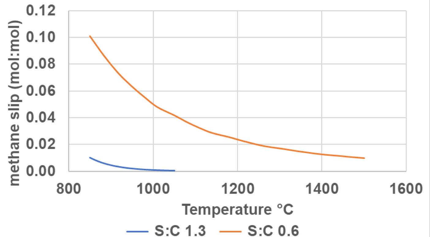
3. Plot of equilibrium methane slip at S:C 0.6 and 1.3 inlet the ATR.
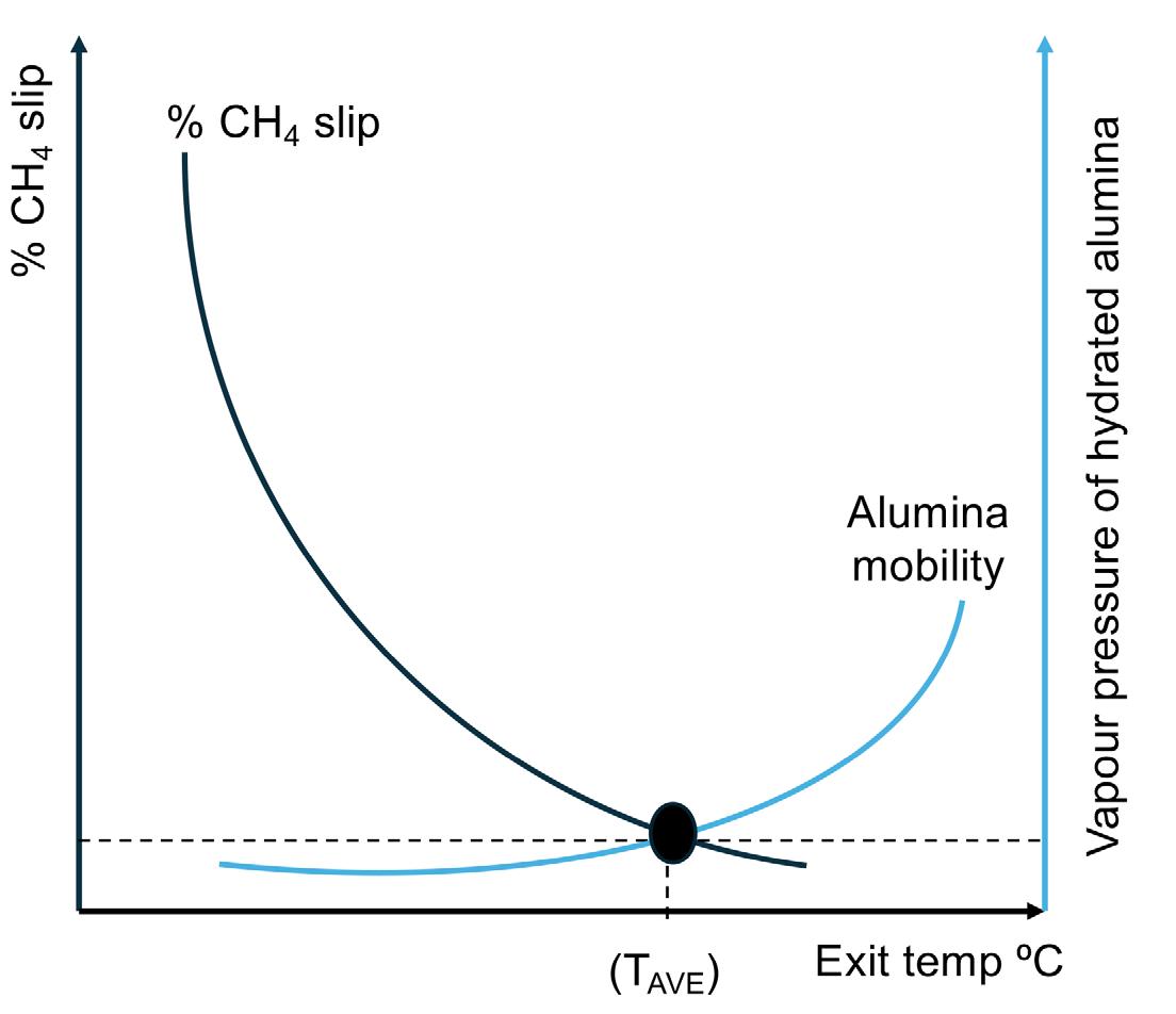
To minimise CH4, a higher exit temperature provides a favourable equilibrium position with respect to reaction 1. However, Figure 4 shows the risk of increasing the exit temperature to be alumina mobility. This is known to adversely impact performance to access the benefit after the plant is commissioned without modification.
So, when thinking of the S:C at the ATR to make blue hydrogen or ammonia, it is important to consider conditions that:
n Minimise CH4 slip, while not unduly stressing the ATR.
n Provide long and efficient operating cycles between plant shutdowns.
In doing this the ATR operation will:
n Minimise CH4 (feed): product.
n Minimise carbon intensity: product.
Where the hydrogen is further processed, the ATR flowsheet should be integrated, for example, with an ammonia synthesis loop in an analogous way to what we know today, that uses high grade steam exiting the secondary reformer. The ATR flowsheet uses the involuntary steam raised from the reformed gas boiler(s), exiting the ATR, to provide motive steam that powers the syngas and refrigeration compressors.
GHR-ATR based flowsheets can be integrated to provide zero steam export from the hydrogen production process. This enables the increased use of external renewable electrical power. This can lower the carbon intensity of the product, and/or lower the cost of the production as less natural gas is needed per unit of ammonia production.
This configuration uses the heat exiting the ATR to directly drive more reforming in a GHR.
Where the GHR replaces the reformed gas boiler, it utilises the high grade heat on the shell side of the GHR. This heat drives approximately 30% of the reforming, through reaction on the tube-side of the GHR, before the gas enters the ATR (Figure 5).
The ATR then completes the remaining 70% of the reforming reaction, through the processes already described in this article. In this case, the size of the ATR, for the same hydrogen production, can be smaller. It follows that the air separation unit (ASU) can also be smaller, as less oxygen is required. This has two effects: n It lowers operational costs, as less power is needed for the ASU.
n It is capital expenditure (CAPEX) neutral, as while the GHR adds a unit-operation, the reformed gas boiler is removed and the ASU is smaller, and so lower in cost.
The transition from grey ammonia to blue ammonia offers the most efficient decarbonisation route for the chemical industry, with proven at-scale technologies. Blue ammonia production offers a pathway to decarbonise fertilizer production, as well as meeting future energy requirements, by using ammonia as an energy vector. Crucially, this will build on existing infrastructure and supply chains. Fully integrated blue ammonia technology can decarbonise the fertilizer production and be one of the solutions to meet the energy transition targets, being aimed at globally.
Reference
1. World Hydrogen Review’, Internqtional Energy Agency (IEA), (2024).
Note
LCH is a trademark of Johnson Matthey PLC. uhde® ammonia process is a trademark of thyssenkrupp Uhde.


Giulia Sporchia and Elisa Brocca, Cannon Artes S.P.A., Italy, analyse solutions and technologies to effectively reduce the water footprint in ammonia production, through water recovery and reuse.
The conventional grey ammonia production process is highly water-intensive, with even higher consumption for blue and green ammonia. Advanced water and wastewater treatment technologies are crucial for enhancing the sustainability of ammonia production. This article analyses solutions and technologies for effectively reducing the water footprint through water recovery and reuse.
Ammonia is one of the most crucial chemicals in the modern world. It is a key component in producing nitrogen-based fertilizers, which are essential for global food production. As the world’s population continues to grow, so does the demand for fertilizers. However, ammonia production presents significant environmental challenges, one which is the large amount of water required for the process.
The Haber-Bosch process has been the cornerstone of industrial ammonia production since the early 20 th century, and remains the dominant method today: ammonia synthesis comes from the reaction between nitrogen and hydrogen at a high temperature and pressure in the presence of iron-based catalysers.
While nitrogen is distilled from air, the hydrogen is produced through steam methane reforming (SMR), in
Conductivity
which natural gas together with steam water produces synthesis gas, which contains hydrogen and carbon oxides.
CH 4 + 2H 2O → CO 2 + 4H 2
Considering only the stoichiometric reactions, almost 1 t of steam water is required to produce 1 t of ammonia (0.8 t of H 2O per t of NH 3).
The stoichiometric consumption further increases when considering blue and green ammonia. For instance, the amount of steam water required doubles when considering green ammonia, arriving at 1.8 t of H 2O per t of NH 3
However, water is not just entering the chemical reaction as a feedstock, but is involved in various stages of ammonia production, making the overall process highly water-intensive.
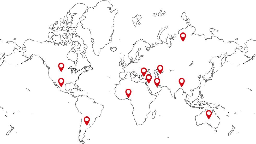
To determine the quantity and usage of the required water, a number of ammonia production plants – where Cannon Artes has either collaborated or supplied water treatment plants – were studied. In particular, several plants with capacities varying from 400 to 4400 tpd of ammonia produced, located in different parts of the world were analysed. Figure 1 summarises the location of the considered plants.
The first part of the analysis carried out consisted in normalising the water consumed for the ammonia produced to determine the typical consumption.
This study allowed us to calculate the amount of water required for the following uses:
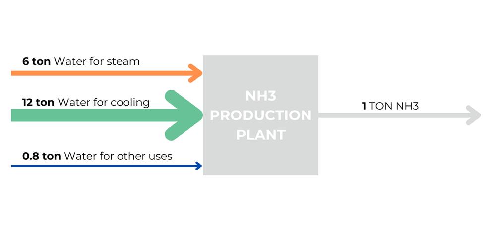
n Water for steam production.
n Water for cooling systems.
n Water for other uses.
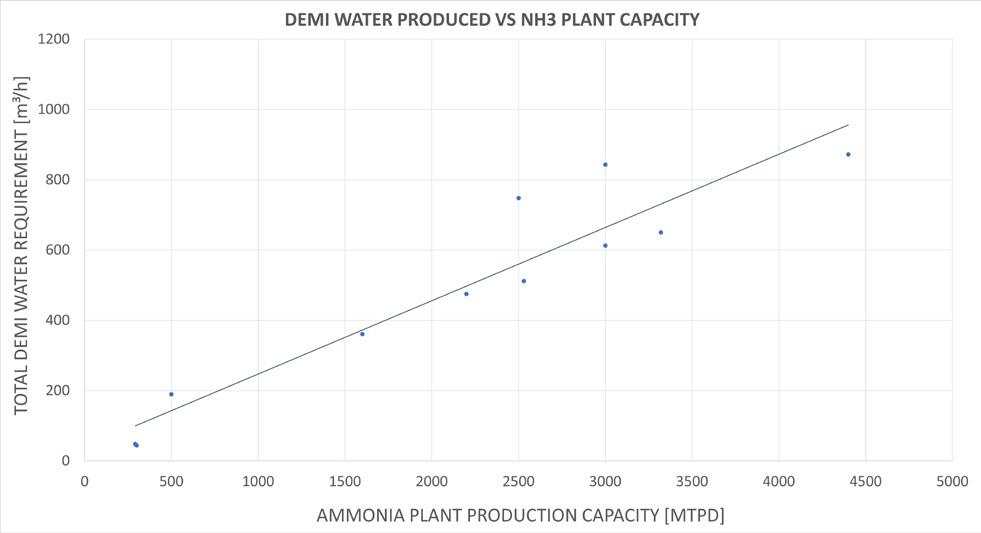
One initial finding from this analysis is highlighted in Figure 2, where it is seen how the demineralised water produced as a function of the ammonia capacity of the different plants demonstrates a clear linear relationship.
Demineralised water is used in steam production in different parts of the plant such as process steam, steam for the ammonia synthesis compressor, steam for the electricity generator, and steam for the CO 2 compressor. These streams require a total amount of approximately 5 - 7 t of demi water per t of NH 3, as seen in the graph in Figure 3.
In particular, water for steam production is required for: n Process steam.
n Steam for the ammonia synthesis compressor.
n Steam for the electricity generator (power turbine).
n Steam for the CO 2 compressor.
The total demi water required is 6 t of demi water per t of NH 3
Water is used as a cooling medium to remove heat produced by exothermic reactions and to condense steam. Cooling water feeds the following equipment, mainly: the blow down cooler, critical oil coolers, seal water coolers, the flushing condensate cooler, the auxiliary boiler blow
Fully automatic packaging machines
Fully automatic high-quality packaging machines for bagging up to 2000 pillow and/or gusset bags per hour.
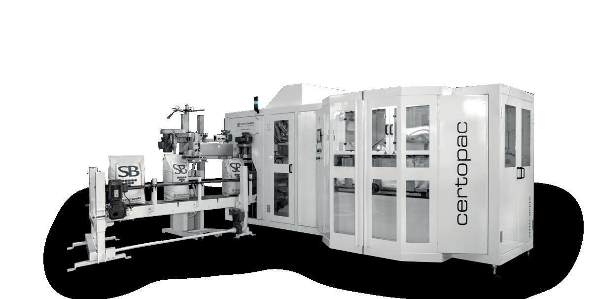
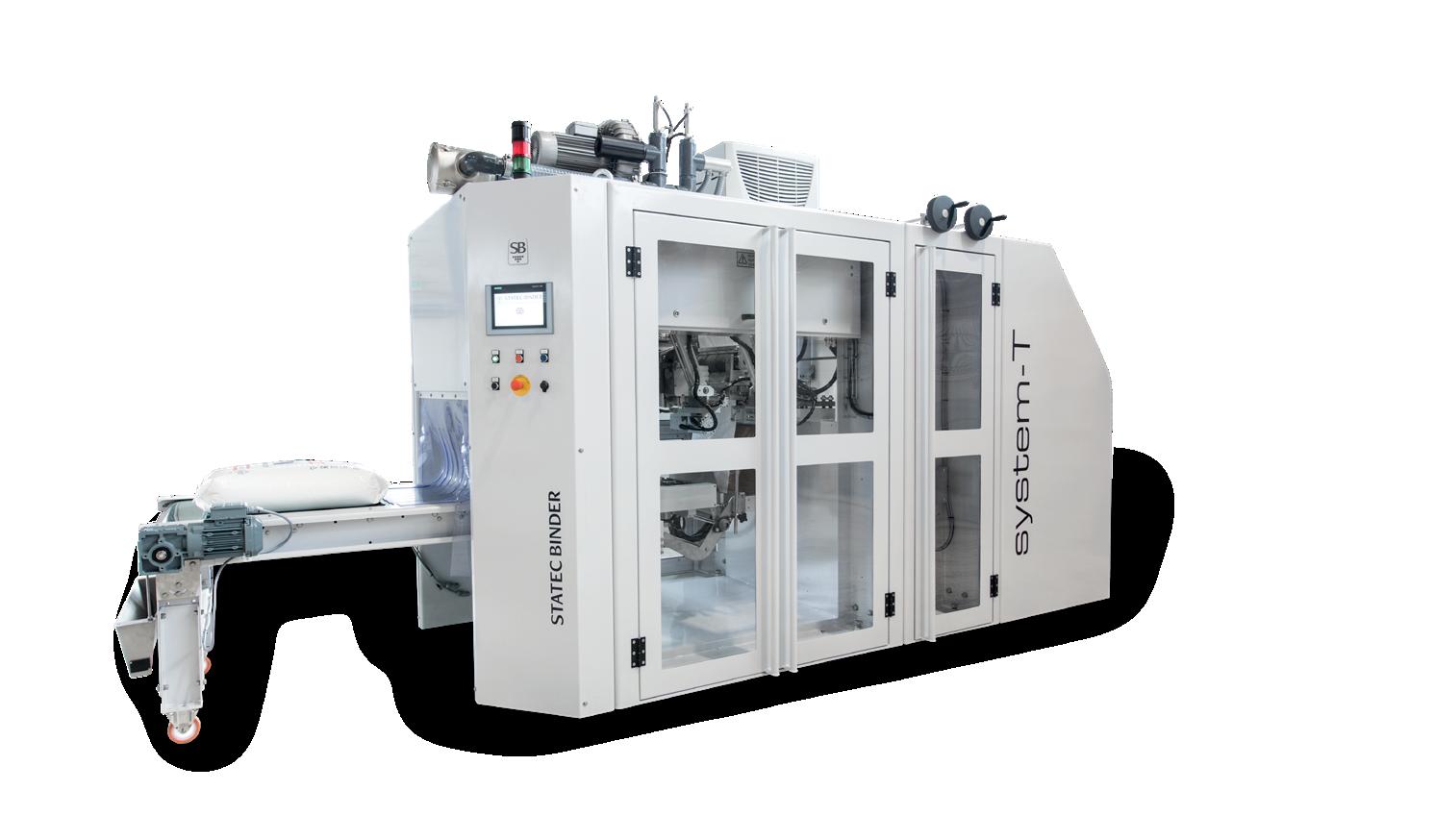
Fully automatic FFS packaging machines
Fully automatic form-fill-seal packaging machines for the production and packaging of up to 2800 bags
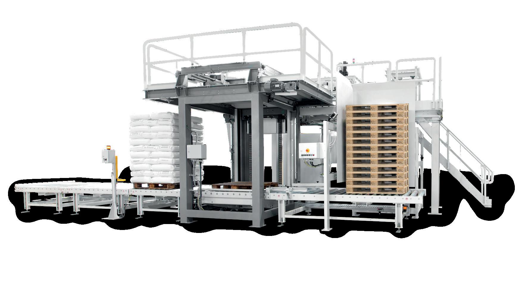
High-performance robot palletizer
High-performance robot palletizer for palletizing up to 3000 bags or cartons per hour.
down cooler, the ammonia storage refrigeration unit, and the instrument air compressor. Different cooling systems are suggested depending on the plant’s location. Using seawater as a cooling medium usually involves closed-loop cooling towers (CT) or once-through cooling systems due to the stream’s high salinity. On the other hand, brackish water (rivers, lakes) can be used in open-loop cooling towers. Different water amounts are consumed depending on the cooling system’s typology. The analysis carried out highlighted how for open-loop cooling towers, considering a concentration factor of 4 - 5, the make-up water contribution is around 12 - 13 t per t of NH 3.
Water is also used for firefighting, drinking water, service water, and in the plant's domestic facilities. The estimation is approximately 0.8 t per t of NH 3
When considering the water that the plant will produce, it is not only important to consider the amount of water produced, but also its required quality, to determine the optimal water treatment.
Table 2. General guidelines for cooling water quality
water quality
Strongly dependent on location and weather conditions
Steam production requires using demineralised water. Depending on the final use of the steam, the demi water quality slightly changes (refer to Table 1).
The required treatments and the consequent achievable recoveries can vary widely depending on the feed water type.
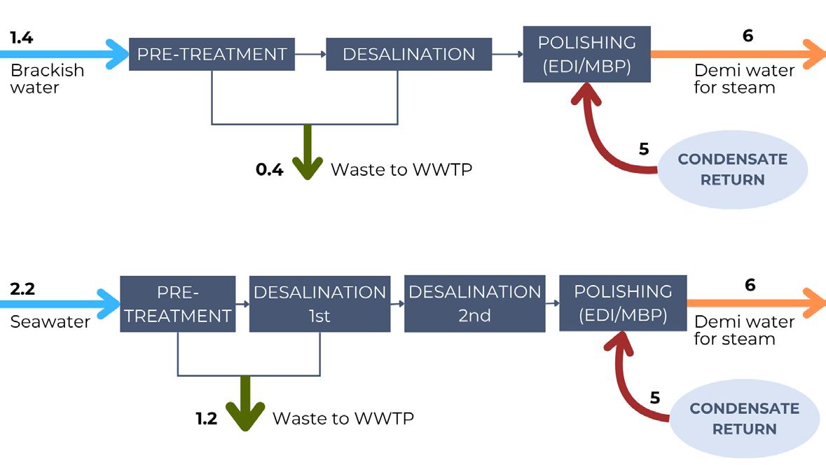
Brackish water is usually associated with a recovery rate of 80% and requires a pre-treatment for solids removal, filtration (on sand and/or ultrafiltration membranes) followed by a demineralisation treatment with IEX (ion exchange, cationic + anionic + MB mixing bed) or with RO (reverse osmosis) + EDI (electrodeionisation).
On the other hand, seawater is associated with a significantly decreased recovery, due to the requirement for a further desalination step. In this case, pre-treatment is followed by a double-pass RO and polishing system, EDI or MBP (mixed bed polisher).
The study carried out took into account plants sourcing from both brackish and seawater. The differences in the water intake and the waste generated for demi water production is highlighted in Figure 4.
In the case of green ammonia, where H 2 is produced through hydrolysis, the required quality depends on the chosen technology. In general, alkaline and anion exchange membrane cells require a maximum conductivity of 5 µ S/cm, proton exchange membrane cells require 0.1 µ S/cm and plants producing more than 100 MW generally require a maximum of 0.056 µ S/cm.
The technologies available to reach these values are the same presented for demineralised water for grey ammonia production (RO followed by EDI or IEX).
Cooling
The make-up water in cooling towers is characterised by a limited salinity and the absence of total suspended solids (TSS). Some general indications on cooling towers’ make-up quality can be found in Table 2.
Depending on the water employed in demineralised and make up water production, different treatment trains may be required. If the water characteristics are comparable to those of river water, achieving these characteristics is possible thanks to a pre-treatment, ensuring that the TSS limitation is met. Furthermore, if the total dissolved solids (TDS) are particularly elevated, an RO treatment is also required.
Pre-treatment usually consists in TSS elimination with a physical separator, followed by multimedia filters and/or ultrafiltration. Once the desired suspended solids level is achieved, the stream can undergo a partial TDS removal. The goal is that of achieving a dissolved solids concentration around 50 - 500 ppm, to avoid salt accumulation and guarantee a suitable number of concentration cycles. The salinity limitation may vary depending on the minimum number of concentration cycles.
In the production plant, water for other uses is also required: fire water, service water and potable water. Removal of suspended solids, organic matter, and


eventually TDS is required. Some further adjustments may be required for producing drinking water. In this case, additional remineralisation and disinfection might be needed. The resulting stream follows the regulations of the country where the plant is located. As a general reference, it is necessary to follow World Health Organization (WHO) parameters.
Once the amount of raw water and the quality requirement have been identified, it is necessary to maximise water reuse. Water reuse involves capturing and recycling water used in the production process rather than releasing it as wastewater. This not only reduces the need for fresh water but also minimises the amount of wastewater discharged into the environment.
A further step in the present study consisted of evaluating the main waste streams coming from an ammonia production plant. Table 3 highlights the main contaminants found in these waste streams, together with the average amount of water associated with the production of 1 t of ammonia.
Condensated streams can be reused entirely. Condensates have different origins and are mostly characterised by the same pollutants. These streams are generally clean and,
after a polishing treatment, can be reused as boiler feed water. The main contaminants present are ammonia, urea, CO 2 , and formic acid, which are usually removed with IEX. Depending on the cases, it may be necessary to use only mixed bed polishing or a more complete treatment including cationic and anionic exchangers.
It was estimated that the condensates reused are approximately 5 t of condensate per t of NH 3 produced, which can be entirely recycled. Their reuse makes up for approximately 80% of the demi water required to produce steam.
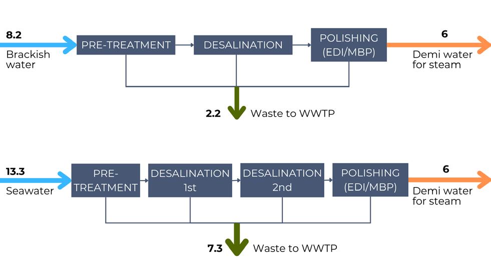
Figure 5 highlights how condensates reuse introduction in the considered plants modified the raw water intake with respect to Figure 4, both in the case of brackish and seawater.
The treatment and reuse of return condensates allows for decreasing the request of raw water from 8.2 to 1.4 t of condensate per t of NH 3 for brackish water and from 13.3 to 2.2 t of condensate per t of NH 3 in the case of seawater.
Polished condensate streams are not the only by-products from an ammonia production plant that can be recycled. Several other waste streams, typically directed to a wastewater treatment plant for disposal, are potentially reusable (Table 3). Each stream has different contaminants and can be treated and reused in different ways.
The stream with the highest flow rate is for cooling tower blowdown. In the case where brackish water is used as raw water, the CT blowdown salinity will be 3 - 5 times more than that of raw water, depending on the number of concentration cycles. A desalination treatment for this stream will eliminate the demand of raw water for demi make up water.
The contribution of rainwater depends upon the location and weather conditions, but its treatment and recovery can be very helpful for further decreasing raw water intake.
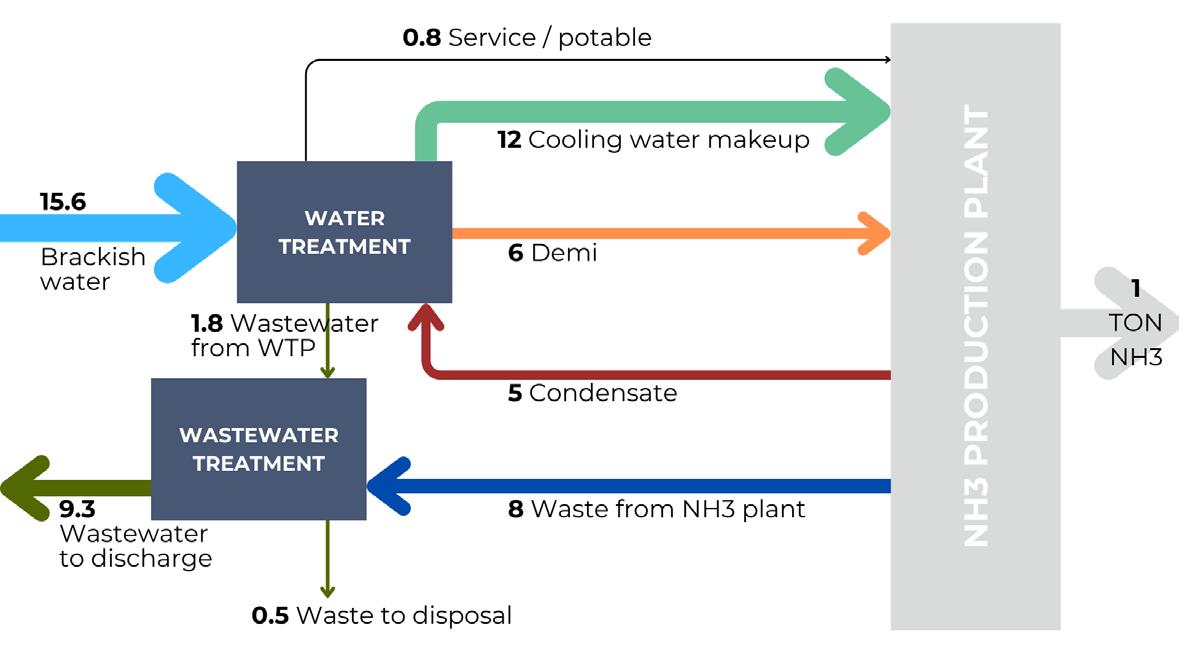
A specific study on wastewater reuse allowed the calculation of an estimation of the water flows involved per 1 t of ammonia production in the case where only condensates are reused, and wastewater is treated and discharged. The result is shown in Figure 6, which was then compared with the case of wastewater recirculation.
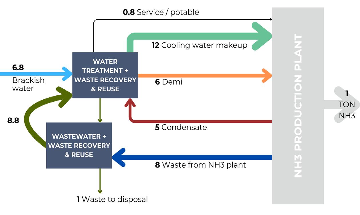
In areas with limited water availability, it becomes necessary to decrease raw water intake, reusing wastewater from ammonia production as much as possible. Considering wastewater recovery, discharge to the environment is eliminated and, as a consequence, water make up is reduced by more than 50%, from 15.6 t of H 2 O per t of NH 3 to 6.8 t of H 2 O per t of NH 3 . Different water needs can be seen in Figure 7.
An example of an integrated water treatment scheme for ammonia production is reported in Figure 8, highlighting a possible treatment and wastewater reuse strategy.
In the example, the following treatment streams are considered:
n Sanitary water, contaminated drain water and fuel gas sour condensate are mixed and treated in a biological system with membrane bioreactor (MBR).
n An accumulation section mixes other waste streams, such as industrial contaminated, cooling towers blowdown and blowdown from boilers, with a portion of river water.
n A chemical-physical treatment is introduced to remove TSS, heavy metals (whenever present), and hardness, with the goal of increasing the recovery of the following sections. This step usually requires dosing of a flocculant and a coagulant.
n A membrane filtration system with ultrafiltration is predicted to achieve negligible TSS content.
n The first reverse osmosis treatment allows for achieving a salinity comparable to that of river water. In this step, antiscalants and acids are dosed to avoid scaling. A portion of the permeate water from first pass RO is then separated and mixed with clean rainwater and make up water from the river. These streams contribute to producing 12 t for cooling tower make up and 0.8 t for other services.
n To produce 6 t of demi water, the remaining fraction from first pass permeate is headed to the second pass of RO, mixed with condensates and sent to the final polishing treatment, with mixed beds ion exchange.
n All waste streams are recirculated in this treatment, including sludge supernatants, filter backwash, RO low salinity concentrates. This strategy allows for as much recovery as possible.
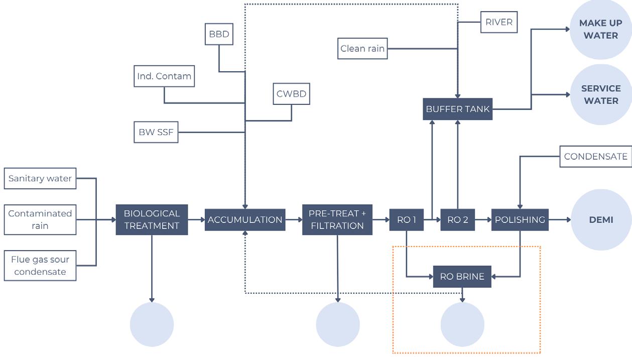
The streams with higher salinity, like first RO concentrate and eluates, are treated with a further RO treatment, maximising the concentration of this stream, reducing the volume that will be sent to final disposal and achieving near zero liquid discharge. Finally, only 1 t, composed of a rejected salty stream and dewatered sludge, is disposed of.
ZLD can be achieved by sending the reject stream to an evaporator, which allows water recirculation (with a previous pre-treatment). This will result in discharging only solid waste: the dried sludge from chemical-physical treatment and salt slurry from evaporator crystalliser.
The analysis carried out on several fertilizer plants highlighted the important water requirement for
nitrogen-based products. As a first step, it was possible to determine the amount of water needed for demi and cooling tower make up water, both substantial for the operation of the fertilizer facility. The raw water requirement for the desired streams was then calculated depending on the source, since brackish water and seawater are associated with different recoveries. The impact of water reuse was then examined, highlighting how condensates and wastewater recycle can contribute to decreasing raw water intake. The main results are collected in Table 4, summarising the water requirements associated with the different cases.


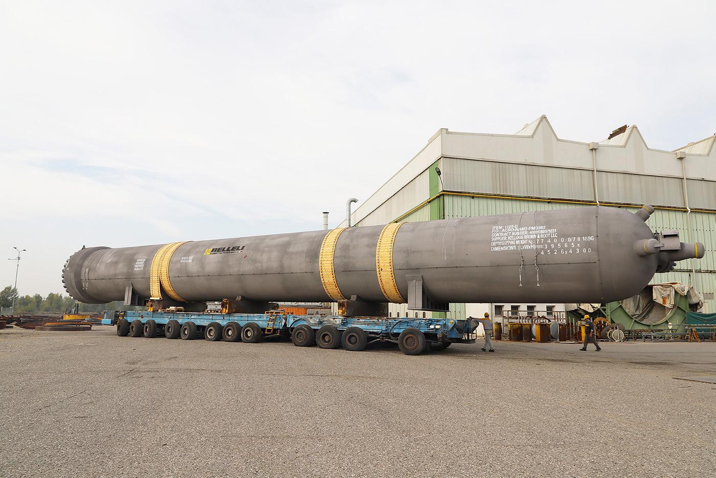
Stefano Alberini, Belleli Energy CPE, Tosto Group, discusses the fabrication of a high-pressure ammonia synthesis converter with enhanced 2.25cr-1mo low alloy steel and advanced welding technology.
The production of ammonia, a critical component of fertilizers and various industrial chemicals, relies heavily on high-pressure synthesis converters. These vessels operate under extreme conditions, demanding exceptional structural integrity and reliability. The fabrication of such converters presents significant challenges, particularly in the welding of thick-walled components, where traditional welding methods can lead to increased weld material volume, residual stresses, and potential defect risks. This article will provide a comprehensive overview of a successful application of enhanced 2.25Cr-1Mo low alloy steel

to fabricate high-pressure ammonia synthesis converters with enhanced overall mechanical properties obtained through the adoption of an advanced welding technolog y.
Enhanced 2.25Cr-1Mo low alloy steel offers a compelling combination of properties that make it well-suited for demanding applications:
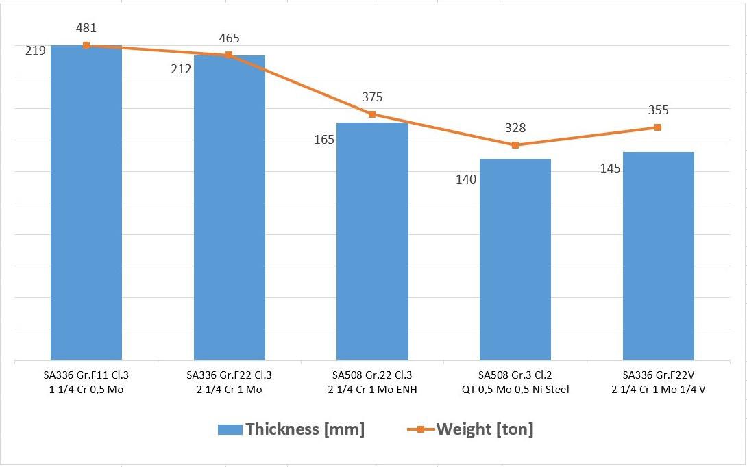
n Enhanced mechanical properties: compared to conventional 2.25Cr-1Mo steel, the enhanced version exhibits superior strength and creep resistance due to a specifically designed heat treatment process involving lower tempering temperatures. This allows for reduced wall thicknesses and weight savings without compromising structural integrity.
n Suitability for high-temperature hydrogen service: while the development of 2.25Cr-1Mo-0.25V steel with its enhanced resistance to high-temperature hydrogen attack led to a temporary decline in the use of enhanced 2.25Cr-1Mo, it has experienced a resurgence in applications where operating temperatures are below its ASME Code allowance (e.g., 454°C), such as ammonia synthesis.
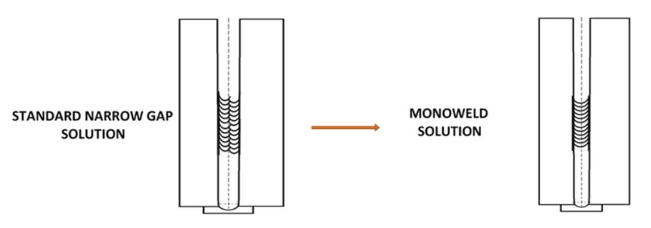

Figure 2. Weld macro-section ‘one-bead-per-layer’ welding sequence.
SA
SA 336 Gr.F22
(2 ¼ Cr 1 Mo low alloy steel)
SA 336 Gr.F22V (2 ¼ Cr 1 Mo
Sa
(2 ¼ Cr 1Mo Enhanced steel)
Notes: * 300°C ASME BPV code Section VIII Div. 2 ** Toughness reference values can vary based upon the involved thickness
n Cost-effectiveness: enhanced 2.25Cr-1Mo steel offers a cost-effective alternative to more expensive high-strength fine-grained steels, which may not be necessary for all ammonia synthesis converter applications. Table 1 shows typical base materials adopted for ammonia synthesis converter and their mechanical characteristics.
The enhanced mechanical properties of 2.25Cr-1Mo steel are achieved by reducing the tempering and post weld heat treatment (PWHT) temperatures compared to the standard grade. While this enhances strength, it necessitates careful control of the heat treatment process to ensure adequate toughness, particularly in the weld zone. Lower PWHT temperatures can make it challenging to achieve the required impact toughness, especially at low temperatures (e.g., -29°C). However, the advanced MONOWELD® technology, with its ability to promote uniform microstructures, can help mitigate this challenge.
High-pressure vessels, such as ammonia synthesis converters, are typically constructed from thick steel plates to withstand the high
internal pressures and temperatures involved in the process. Welding these thick sections poses several challenges:
n Increased weld volume: traditional multi-pass welding techniques require substantial weld material, increasing the risk of defects and distortion.
n Residual stresses: the heat input during welding can induce significant residual stresses in the joint, potentially compromising its integrity.
n Hydrogen embrittlement: ammonia synthesis involves high-pressure hydrogen environments, which can lead to hydrogen embrittlement in susceptible materials, particularly in the weld zone.
n Toughness requirements: maintaining adequate toughness, especially at low temperatures, is crucial for preventing brittle fracture in high-pressure vessels.
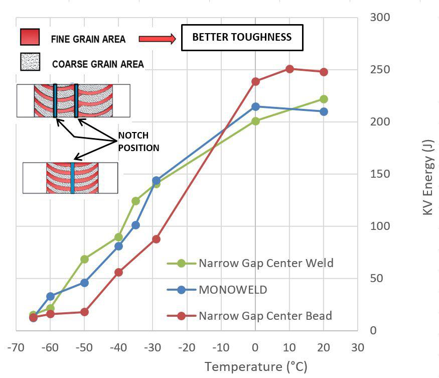
To address these challenges, conventional welding practices for high-pressure vessels often employ narrow gap welding techniques. This approach utilises a specialised joint preparation with a narrow groove, minimising the volume of weld metal required. Typically, a two-bead-per-layer welding sequence is employed with submerged arc welding (SAW), a process known for its high deposition rates and ability to produce high-quality welds.
While effective, this method still involves multiple passes and can be time-consuming.
The advanced MONOWELD technology represents a significant departure from conventional narrow gap
Wondering what other machines we offer and how we can assist in your situation?
Scan the QR-Code and take a look at our website.
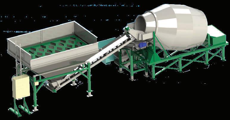
For more than 35 years EMT has proven to be the right partner for all mixing, bagging and conveying machines.
• Capacities from 25 to 75 tons per hour
• Machine sizes of 4.5-5.4-7-9-11.5-14 tons
• Simple and subtle mixing process
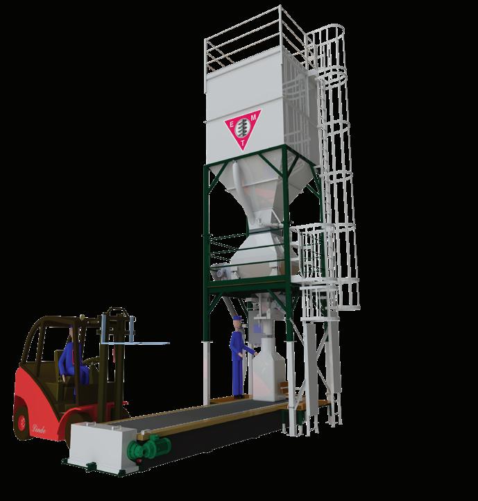
• For big bags/Jumbo bags
• Capacity of 50 to 70 tons per hour
• 500 kg to 1250 kg bags
• Also systems of 120/180 tons per hour available
• Custom made
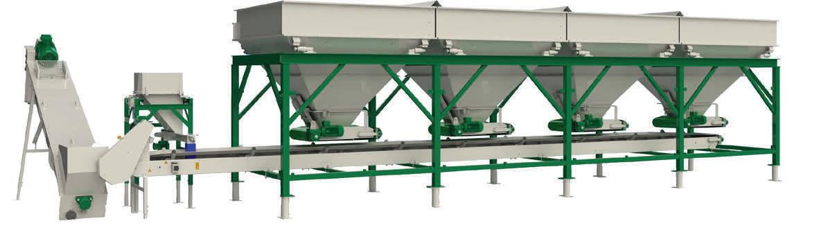
• Unlimited number of weighing bunkers
• Capacity from 20 to 300 tons per hour
• Fully automatic computer controlled mixing process
The successful implementation of the technology required extensive development and optimisation efforts, focusing on three key aspects:
n Weld bevel design: the bevel design was carefully engineered to facilitate proper fusion and penetration with a single-bead-per-layer sequence.
n Welding parameter selection: extensive experimentation was conducted to determine the optimal welding parameters, including current, voltage, travel speed, and wire feed rate, to ensure consistent weld quality and performance.
n Welding torch design: a specialised welding torch was developed to accommodate the single-bead-per-layer technique and provide precise control over wire positioning within the joint.
The chosen welding process, tandem submerged arc welding with two wires, offers high deposition rates and excellent weld quality. The custom-designed torch further enhances control and precision, crucial for the success of the advanced welding technology.
Macro-sections of welds produced (Figure 2) reveal uniform and regularly distributed weld bead shapes and dimensions.
welding practices. It introduces a single-bead-per-layer welding sequence, effectively reducing the number of passes required to complete the weld joint (Figure 1).
This innovative approach offers several advantages:
n Reduced weld volume: by minimising the number of passes, the advanced technology significantly reduces the volume of weld metal, leading to lower distortion and a decreased risk of defects.
n Improved weld quality: the single-bead-per-layer technique promotes better fusion and reduces the likelihood of slag inclusions and other imperfections.
n Reduced residual stresses: fewer welding passes translate to lower overall heat input, minimising residual stresses in the joint.
n Enhanced toughness: the technology, when properly optimised, can contribute to more uniform and consistent toughness properties in the weld zone.
Comparing these to traditional narrow gap welds based on a two-beads-per-layer technique highlights the ability of the technology to eliminate significant variations in the weld microstructure, contributing to improved mechanical properties and reduced susceptibility to localised weaknesses.
Toughness, a critical property for pressure vessels operating in demanding environments, was rigorously evaluated through Charpy V-notch impact testing. To assess the impact of weld bead placement on toughness, impact test specimens were extracted from standard narrow gap welds with notches located at the weld centre and the bead centre.
Impact tests were conducted at various temperatures to compare the performance of the different welding sequences and notch locations. The results (Figure 3) demonstrate that while the standard narrow gap technique also performed well, the MONOWELD technology exhibited more uniform and consistent toughness across the weld
joint, minimising the potential for localised brittle fracture.
The 2,25 Cr1Mo Enhanced material has been safely applied to four ammonia vessels, of which three are already in service with a thickness range between 180 - 225 mm. Figure 4 shows a completed ammonia synthesis converter.
All welds were produced and subjected to comprehensive non-destructive testing, including manual and mechanised time of flight diffraction (TOFD) ultrasonic examination in accordance with ASME Code Section VIII, Division 2, paragraph 7.5.5. All inspections confirmed the high quality and integrity of the welds produced.
The welding technology achieved a substantial reduction in weld volume, exceeding 30%, compared to conventional narrow gap welding, while simultaneously enhancing weld quality and consistency. This reduction in weld volume directly translates to a lower probability of weld defects. Moreover, the single-bead-per-layer approach eliminates the need for frequent torch repositioning, further minimising the risk of errors and associated defects.
The successful adoption of the enhanced 2.25Cr-1Mo steel in conjunction with the technology offers numerous benefits for the fabrication of high-pressure ammonia synthesis converters:
n The low alloy steel can be considered suitable for the design of ammonia converter pressure equipment in the presence of hydrogen pressure.
n The materials can grant good toughness up to -29°C.
n To grant the required mechanical properties, the tempering and PWHT temperatures shall be carefully designed by the base material supplier and fabricator.
n The welding technology, based on submerged arc welding and a single-bead-per-layer sequence, has proven to be a highly effective and innovative solution for welding Enhanced 2.25Cr-1Mo low alloy steel in the fabrication of high-pressure ammonia synthesis converters.
n 2,25 Cr -1Mo enhanced holds high mechanical properties, providing an optimised solution in terms of the pressure equipment dimensions (thickness and weight) for the typical ammonia equipment design condition.
Figure 5 shows a comparison of the different materials in terms of thickness and weight.
Based upon the data showed, it appears that the carbon moly nickel high strength steel (Sa 508 Gr.3 Cl.2) could provide an excellent solution in terms of wall thickness and weight.
However, in a high hydrogen pressure environment, it could be preferable to stay with low alloy chromium steel materials, which are well known to be highly resistant to hydrogen attack.

This combination of advanced welding technology and high-performance materials offers significant advantages in terms of safety, reliability, cost-effectiveness, and efficiency.
Since 1897, Sackett-Waconia is a diversified manufacturer of high-quality fertilizer equipment, offering solutions from production plants to terminals and blending facilities.


Greg Gedney has over 30 years of experience in the elastomer/thermoplastic sealing and composites industry. He has held roles including Product Manager, Equipment and End-user Segment Manager, and Global Engineering Manager, where he has always been motivated to solve his customer's most challenging issues. Greg graduated with a BS degree in Mechanical Engineering from Auburn University, Alabama, US.
Q: How can sealing solutions help to improve efficiency in the fertilizer industry?
A: Advanced sealing solutions, such as Greene Tweed’s labyrinth seals made of advanced thermoplastic PEEK Arlon® 4020 material, play a vital role in four key areas:
n Reducing leakage: this directly improves efficiency in processes such as air separation during ammonia production in the fertilizer industry. The reduced leakage directly improves compressor efficiency, leading to energy and cost savings.
n Improving efficiency: Arlon 4020 labyrinth seals tighten the clearance between the rotor and labyrinth seal tooth profile, restricting gas flow and delivering efficiency gains of up to 1.5%.
n Durability and resistance: high-performance materials such as thermoplastic PEEK provide excellent resistance to harsh media environments (e.g., ammonia production processes).
The PEEK composite labyrinth tooth can also withstand contact with the rotor during upset (i.e. high vibration) conditions and return to its original shape without wear.
n Energy savings: increased compressor efficiency reduces energy consumption, which can significantly lower operating costs and carbon footprints in energy-intensive industries like fertilizer production.
Q: Can you provide any case studies where seals have helped to achieve efficiency gains?
A: Greene Tweed’s Arlon 4020 labyrinth seals have enabled MAN Energy Solutions to significantly improve the efficiency of its centrifugal compressors, resulting in significant life cycle cost savings for its customers. Typically, leakage across metallic labyrinth seals causes efficiency losses in compressors of ~4%. Arlon 4020 seals, featuring a flexible tooth profile and optimal clearances, improve the compressor efficiency by 1 - 2%.
Theoretical efficiency gains of 1 - 1.5% (calculated through FEA/CFD analysis), and thoroughly evaluated during laboratory testing at the MAN Energy R&D facilities, have now been proven during an extensive field trial at an air separation plant in Hamburg, Germany. The Arlon 4020 labyrinth seals installed in January 2016 were removed after nearly nine years of use in November 2024. After removal, the seals showed no significant wear or corrosion, maintaining key parameters like diameter and roundness. Field tests validated greater than 1% efficiency improvement. For a typical new booster air compressor with four closed impellers and a 3 MW average power per stage, this efficiency boost translates to an estimated total lifecycle cost savings of US$300 000, based on an average power cost evaluation of US$0.025/kWh.
Q: What is your R&D process to develop new seals?
A: Collaboration is at the heart of what we do. By working closely with original equipment manufacturer (OEM) customers and end users across the industries we serve, our engineers identify critical gaps, anticipate future needs, and align our product roadmap with what will benefit our customers’ operations the most.
Four core priorities drive our R&D efforts: reliability, efficiency, safety, and sustainability. These pillars guide every project, ensuring that our innovations not only deliver exceptional performance, but also contribute to a safer, more efficient, and environmentally responsible future.
Q: What tests can be carried out to ensure the properties of sealing solutions?
A: Theoretical simulations, using finite element analysis (FEA), are essential for optimising seal performance before production. Predictive calculations refine performance under various conditions, ensuring seals meet top standards. Rigorous validation follows with pressure, temperature, and durability testing to assess performance under extreme conditions. Comprehensive lab tests and real-world field trials then benchmark performance, guaranteeing the seals function optimally in practical applications.
Q: What were the biggest technical challenges in replacing traditional metallic labyrinth seals in the case study, and how were they overcome?
A: MAN Energy faced challenges with its four-stage compressors due to significant leakages in metallic labyrinth seals, which reduced efficiency and increased energy consumption. Switching to Greene Tweed’s advanced thermoplastic PEEK Arlon 4020 labyrinth seals resulted in a >1% increase in compressor efficiency and reduced energy use.
Another issue arose from the need for large clearances in metallic seals to manage thermal expansion, which led to gas leaks and further efficiency losses. The flexible tooth profile of the Arlon 4020 seals allowed for tighter clearances while accommodating thermal and pressure variations, improving efficiency without causing wear or damage.
Corrosion and erosion from high-acidity or high-velocity environments also posed a problem for conventional metallic seals, resulting in frequent maintenance and replacements. The PEEK material in the Arlon 4020 seals offered excellent resistance to corrosion and erosion, extending the lifespan of the seals.
Boosting Efficiency and Sustainability in Fertilizer Production with Advanced Sealing Solutions
Greene Tweed’s labyrinth seals play a vital role in four key areas:
> Reducing Leakage
> Improving Efficiency
> Durability and Resistance
> Energy Savings
LEARN MORE
Scan Code to Download Greene Tweed’s Case Study
Kevin De Bois, Prayon, Belgium, explores advanced chemical benefication techniques within the phosphate processing industry.
The global economic landscape for phosphate processing has seen significant shifts over recent years, largely driven by the escalating costs associated with high-grade phosphate rock. These costs have surged at a rate surpassing that of phosphoric acid, which is particularly challenging for
acid producers who depend on external phosphate rock supplies.
Integrated producers who manage their own phosphate mining operations face different, yet equally pressing, challenges. As the market demands evolve, particularly in relation to impurity levels for
heavy metals and other harmful elements, these producers must continuously adapt to stay competitive. Meanwhile, high-quality phosphate reserves are becoming increasingly scarce, making it more difficult to procure premium raw materials. As a result, the industry must rely on lower-grade phosphate rock, which introduces its own set of operational and technical complexities.
In response to these challenges, the phosphate industry is focusing on the development of advanced chemical beneficiation techniques. These techniques are intended to complement traditional mechanical beneficiation methods in the phosphate rock processing chain. The primary goal of these processes is to enhance the purity of phosphate rock by selectively removing undesirable impurities, all while ensuring that the phosphorus (P 2 O 5 ) content remains unchanged, or is even enhanced. This process is essential for maintaining both the economic viability and environmental sustainability of phosphate acid production. Several promising chemical leaching methods have been developed as targeted solutions for specific impurities, including magnesium, cadmium, and total organic carbon (TOC). These methods are critical in enhancing the overall quality of phosphate rock, facilitating better phosphoric acid production, and meeting stringent regulatory standards, particularly in markets with high environmental expectations.
One of the major impurities in phosphate rock is magnesium, often found in the form of dolomite (CaMg(CO 3 ) 2 ), which can significantly affect phosphoric acid production. Magnesium can hinder process efficiency and compromise the quality of the final product. The magnesium leaching process involves a highly selective dissolution of carbonate impurities using sulfuric acid, which targets magnesium while leaving phosphate minerals relatively untouched. The reaction mechanism can be simplified as follows:
CaMg(CO
Through this reaction, magnesium ions are selectively dissolved into solution, while the phosphate rock’s valuable phosphorus content remains intact. After leaching, a solid-liquid separation process typically achieved by vacuum filtration, is used to isolate the treated
phosphate rock from the leachate containing dissolved magnesium ions. The result is a purified phosphate rock with significantly reduced magnesium content, making it more suitable for phosphoric acid production.
Experimental results from various studies show that this magnesium reduction technique can achieve up to 60% reduction in the magnesium oxide (MgO) content, while maintaining phosphate (P 2 O 5 ) recovery losses to a minimal level of less than 5%. Such a reduction in magnesium content is critical for improving the efficiency of downstream processing steps, particularly in the production of phosphoric acid. Moreover, this process enables the utilisation of high-magnesium ores, which were previously considered unsuitable for efficient phosphoric acid production, thereby unlocking new sources of phosphate rock for the industry.
Table 1 summarises the analytical results of magnesium leaching, demonstrating the significant reduction in magnesium content, as well as the minimal losses in phosphorus.
The precipitated magnesium sulfate formed during the leaching process can be further processed for reuse in other industries, such as agriculture and water treatment, or safely disposed of, depending on its concentration and purity.
Cadmium is another impurity that poses significant challenges in phosphate processing, particularly in the context of phosphatic fertilizers. Cadmium is a naturally occurring trace element in phosphate rock, and its presence in the final product is strictly regulated due to the toxicity and environmental concerns associated with cadmium. The European Union (EU) and other regulatory bodies have implemented stringent guidelines for the permitted cadmium levels in fertilizers, with an emphasis on progressively reducing these limits. As a result, phosphate producers must find new methods for removing cadmium from their raw materials to ensure that their products remain compliant with these evolving regulatory standards.
Cadmium selective leaching using chloride-rich solutions – such as seawater – has been developed. This method takes advantage of cadmium’s high affinity for chloride ions, allowing for its selective solubilisation:
This approach ensures that cadmium is effectively solubilised while maintaining a high recovery rate of P 2 O 5 The resulting filtrate is treated to precipitate cadmium as an insoluble compound, which can then be safely removed from the process. Pilot-scale trials have shown promising results, with cadmium concentrations reduced by up to 92%, while phosphorus recovery remains nearly unaffected, with over 92% of the P 2 O 5 retained.
This selective cadmium removal method offers a viable solution for phosphate producers looking to comply with stringent regulatory requirements without incurring the high costs typically associated with
cadmium removal techniques.
TOC can be a significant impurity in phosphate rock, primarily originating from organic matter within the ore.
The presence of TOC negatively affects the filtration process in phosphoric acid production, resulting in lower slurry filterability and reduced throughput in the plant. Additionally, TOC contributes to the formation of complex organic compounds, which complicates the downstream acid purification process and reduces the overall quality of the final product.
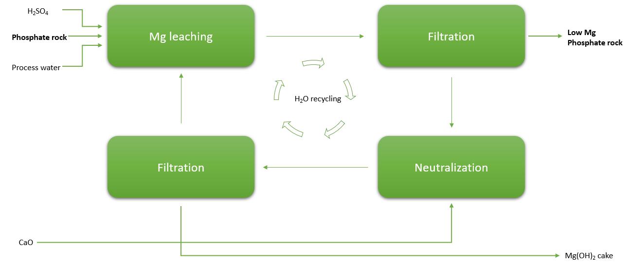
improving filterability and ensuring better efficiency in subsequent processing stages.
To address this issue, various TOC removal strategies have been developed. These methods primarily focus on optimising the leaching conditions to selectively solubilise organic carbon, while minimising phosphorus losses. Key factors influencing the dissolution of TOC include residence time, temperature, and pH control. By carefully adjusting these parameters, phosphate producers can effectively remove a significant portion of the TOC,
In addition to chemical leaching methods, biological treatment strategies have been explored for TOC degradation. These methods leverage microbial oxidation to break down organic compounds into simpler, less harmful substances.
To maximise the benefits of magnesium, cadmium, and TOC leaching, an integrated leaching flowsheet has been developed (Figure 1). This consolidated process flow incorporates all three leaching steps in a sequential
manner, ensuring that each impurity is efficiently removed while minimising any adverse effects on phosphorus recovery.
The primary stages of this integrated process include:
n Leaching: selective dissolution of target impurities using sulfuric acid for magnesium and TOC leaching; and chloride-rich solutions for cadmium leaching.
n Filtration: separation of the treated phosphate rock from the leachate containing dissolved impurities.
n Neutralisation: pH adjustment using lime or alternative neutralising agents to precipitate unwanted species, such as calcium sulfate or magnesium sulfate.
n Solid-liquid separation: recovery of purified phosphate rock and removal of precipitated by-products, such as cadmium sulfates or organic matter.
In terms of by-product management, the process is designed to ensure that waste generation is minimised. Magnesium-containing residues from the leaching process can be reintroduced into fertilizer formulations, providing a valuable resource for agricultural applications.
Cadmium-rich precipitates, on the other hand, require careful disposal, as cadmium is a toxic heavy metal. To minimise environmental impact, these by-products are processed in compliance with stringent environmental regulations. The treated water from the leaching process is fully recycled, with only minor losses attributable to filter cake moisture content.
The depletion of high-quality phosphate reserves presents a significant challenge for the global phosphate industry. To address this challenge, the adoption of advanced beneficiation techniques is essential for ensuring both economic and environmental sustainability in phosphoric acid production. The chemical leaching processes discussed in this paper offers targeted solutions for impurity removal, allowing producers to efficiently process lower-grade phosphate rock.
Key findings from this research include:
n Magnesium leaching: effectively reduces magnesium oxide (MgO) content by 60%, enabling the utilisation of magnesium-rich ores that were previously considered unsuitable for phosphoric acid production.
n Cadmium leaching: achieves 92% cadmium removal, with 92% recovery of phosphorus, ensuring compliance with stringent regulatory standards.
n TOC leaching: reduces organic carbon content by up to 99%, significantly improving filtration efficiency and overall plant throughput.
The integration of these advanced leaching technologies into a closed-loop system significantly reduces waste generation and enhances process sustainability. As the phosphate industry continues to face evolving challenges, further research will focus on optimising leaching parameters, exploring additional impurity removal strategies, and developing more sustainable practices to meet the growing global demand for phosphate products.
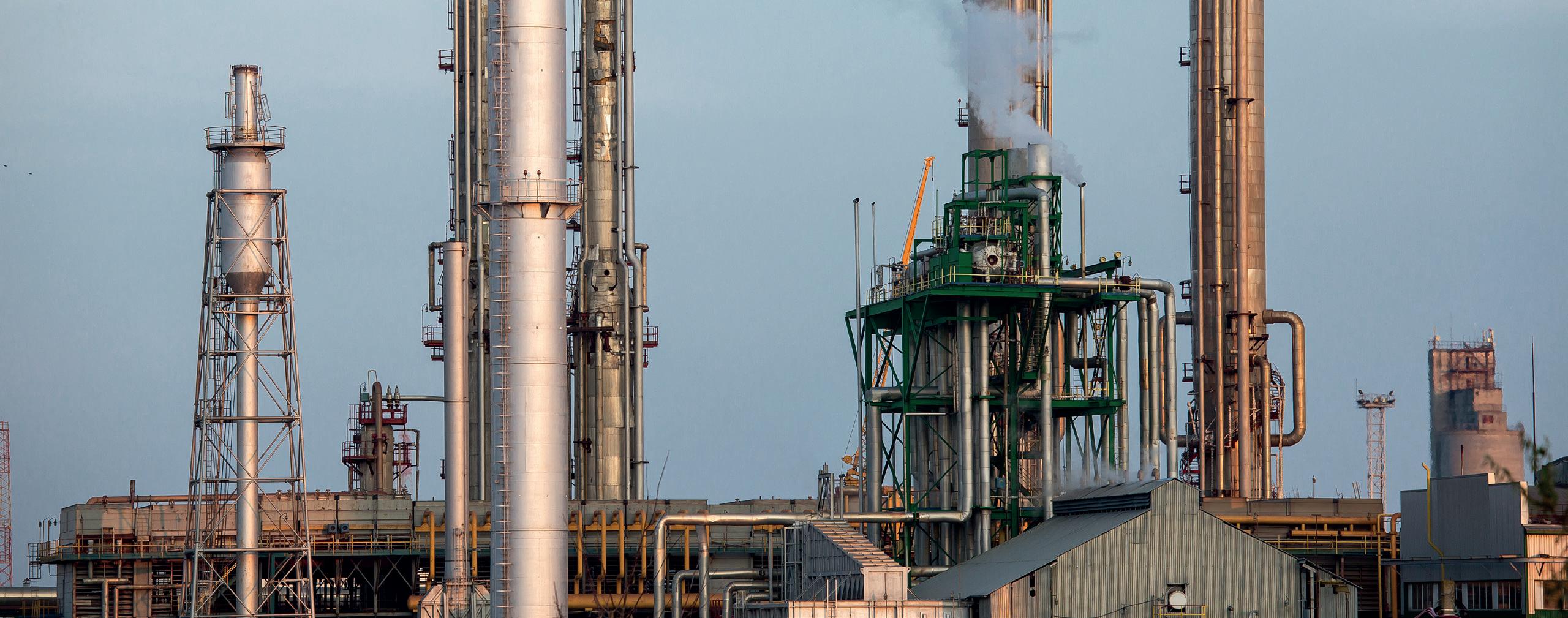
• Market analysis
• In-depth technical articles
• In-depth regional analysis by key players in the industry
• Comprehensive technical reviews covering all aspects of fertilizer production, from plant optimisation and automation to blending, bagging, and dispatch


Ian K. Hancock, Bradley Pulverizer, UK, discusses classifier options for improved fertilizer milling.
Air classifiers are essential for controlling the product size, particle recirculation, power consumption, and overall profitability of an airswept mill system. Several different types of classifiers are available with each having its optimal performance ranges and applications. Classifier selection and performance optimisation are critical as they directly impact overall fertilizer mill system performance and efficiencies. Ongoing advances in classification technology are leading to further enhancements in yields and efficiencies.
Fine grinding of hard, friable material such as phosphate rock with an air-swept mill involves the continuous return of oversize material to the mill’s grinding zone for further reduction until the desired size is met. It is the role of the classifier to control both the amount of recirculation inside the mill and the particle-size distribution of the end product, with changes in a classifier’s settings having direct effects on the milling system’s power consumption, capacity, vibration, and product size distribution.
Essentially, the classifier functions as the controls of the grinding circuit, determining both the material that
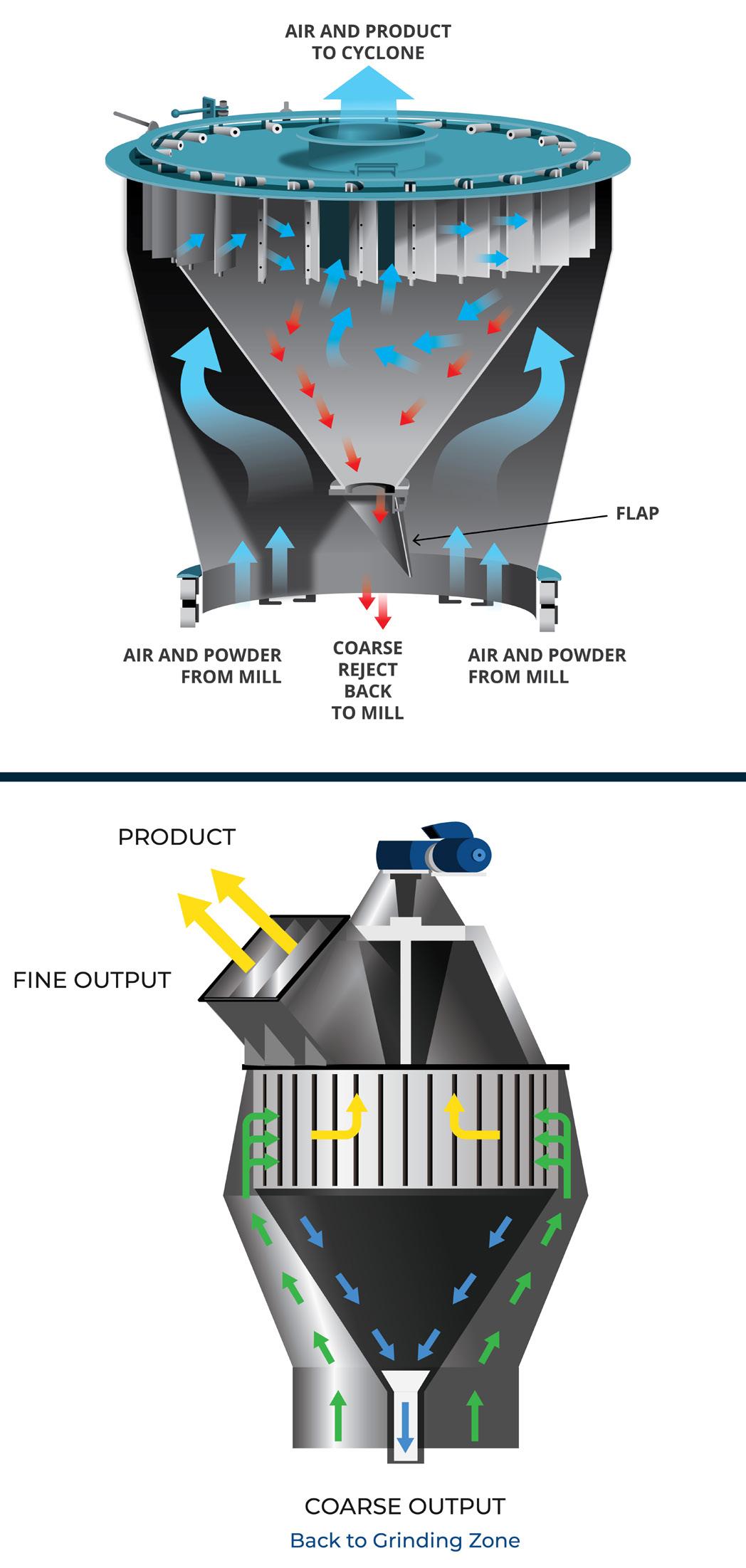
should exit the mill as correctly sized product as well as what should be returned for reprocessing.
There are four main mill classifier types:
n Static classifiers: these are fixed volumetric classifying devices with lower maintenance requirements, however, increases in fan volume will directly increase particle size and decrease cut efficiencies.
n Dynamic classifiers: most commonly found in fertilizer applications, these incorporate a rotating rotor vane to enhance particle classification and, consequently, have a wider operational range.
n High efficiency classifiers: ideal for cement applications, these combine useful elements from both of the above technologies by using a static set of vanes to guide the airflow into a rotating rotor, alongside other optional features for higher level of particle control.
n Divorced classifiers: also common in fertilizer applications where very fine particles (<45 µ m) are specified. Divorced classifiers take particle recirculation outside of the mill’s airstream and provide the opportunity to efficiently generate multiple product sizes from a single feed.
All classifiers have an efficiency rating, reflecting how well they separate material. Some are very efficient while others are less so. Inefficient classifiers are unable to achieve a good fine/coarse separation. This means the product stream will contain some coarse particles and the reject stream will contain fine material. This creates additional and unnecessary demand on the mill, resulting in higher recirculation rates which in turn requires more fan pressure and increases the power requirements of the fan drive.
A classifier’s operational efficiency is determined from the ‘tromp curve’ – a graph plotting percentage classifier rejects against particle size. Essentially, this curve shows how much on-size recovery there is in the reject stream. Curves which are as close as possible to a vertical straight line at the cut point are theoretically ideal. Less efficient static classifiers typically show gently sloping lines, whereas more vertical lines – closer to the maximum theoretical limit – are shown by high efficiency classifiers.
Oftentimes, efficiency analyses for existing mill systems will demonstrate opportunities where upgrades to the classifier will improve efficiencies and overall profitability. Upgrading an existing mill system with a new, correctly installed high efficiency classifier can deliver:
n An increase in overall milling system capacity.
n Reductions in power consumption, often up to 8%.
n Sharper classification curves.
In the fertilizer industry, dynamic vertical blade classifiers (VBC) are commonly specified for several reasons. VBCs are favoured because they offer high ‘uptimes’ with minimal maintenance and low percentages of rejected particles. They are also relatively low cost and return a quick return of investment (ROI). Dynamic classifiers such as the VBC provide wide flexibility of operation by
allowing for instant adjustment of particle separation ranges.
This dynamic classifying technology utilises vertically oriented blades and a separator rotor to create a vortex, spinning the passing air and throwing coarse particles out to the sides of the mill where they fall back into the grinding zone. Desired fine particles are carried out through the separator rotor, and up to the cyclone or bag filter collector. Power reductions result from a reduction in the amount of regrinding that occurs and a lessening of the ‘clouding’ effect that is caused by a mixture of fine and large particles occurring within the grinding chamber with an improperly balanced gas flow.
Another advantage is the ability to automate particle size control when coupled to an inverter (variable speed drive, [VSD]). The product size is controlled by changing the rotor speed. This is done by an inverter drive and can be adjusted with the mill online. This type of separator allows maximum efficiency and stable product size.
Demand is on the rise for milling systems with expanded capabilities and improved performance.
Divorced classifiers take particle classification outside of the mill’s grinding chamber, which allows for expanded capabilities such as simultaneous production of multiple end products of different size specifications from a single feed continuous processing system. In fact, there are
divorced classifiers currently in operation that are simultaneously producing four or more different sized commercial products.
For example, airswept pendulum roller mills are typically employed to pulverise rigid/friable materials into fine powders from 50% passing 150 µ m to 99.9% passing 30 µ m , whereas vertical shaft impact crushers are employed to crush rigid and friable raw materials to coarse grit specifications. Impact crushers require a capitol cost to purchase and have high energy demands to operate and cannot produce high yields of fine particles. Divorced classification milling systems, on the other hand, can produce high yields of both fine powders and coarse grit in one operation, in one machine, with a much lower demand for energy consumption. In fact, the same amount of power is required to generate fine powders as it is to generate both fine powders and coarse grits. Zero additional power is required to generate two products simultaneously vs just one.
Additionally, divorced classifiers can significantly increase milling efficiencies in fertilizer applications when materials are particularly difficult to grind and/or there is a demand for very fine (<45 µ m ) product. Mill classifiers lose efficiency when very fine particles are specified because more grinding is required to meet the specification, so more time is required in the recirculating airflow within the mill chamber. The result is an unwanted mixture of particles that hovers in the mill’s grinding chamber consisting of fine particles that are near spec but not heavy enough to fall and are caught in their own airstream

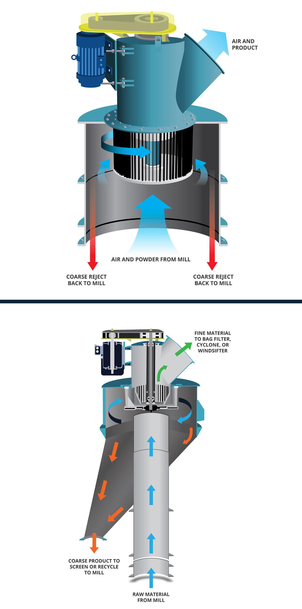
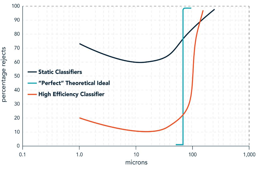
midway up the grinding chamber. This ‘clouding’ of particles within the grinding chamber significantly reduces efficiencies and leads to increases in maintenance requirements.
Divorced classifiers alleviate clouding in mill systems by taking particle classification outside of the mill’s grinding chamber, thus creating a one-way flow of air through the mill chamber vs recirculating the airflow within the chamber. After feed materials are ground in the mill chamber, the one-way airstream takes all particles out of the mill to the divorced classifier where fine particles exit to storage while coarse particles are directed back into the mill chamber for further grinding. The result is very often higher profitability from reduced vibration/less maintenance, better particle size consistency, and throughputs up to 15% higher.
Existing milling systems can be converted to divorced classification milling systems relatively easily by reconfiguring the fan and classifier configuration attached to the mill. Furthermore, by combining the Bradley Windsifter classifier to the divorced classification system, up to seven (or more) products of different size can be produced simultaneously.
It is the classifier that ultimately controls a mill’s yield rate and hence the overall profitability of the plant. It is therefore imperative to evaluate both the mill and classifier together as a single system and not independent of one another.
The same ethos applies to post startup problem solving. It is recommended that a structured or holistic approach is taken when troubleshooting production issues, with scrutiny of the process itself to identify the true cause of the problem. After all, the problem that presents itself may well have an indirect cause. If the mill is apparently lacking power, for example, the right solution may not be installing a bigger motor or investing in a new more powerful mill. Instead, the problem could be solved – and often is – by making air flow adjustments at the mill and/or classifier.
Unfortunately, mill systems were not encountered where the classifier was not evaluated properly prior to installation and cannot achieve the yields required to achieve profitability. In such cases, it is still more cost effective to replace the classifier than the mill.
Most problems encountered in milling systems could ultimately have been avoided from the outset if: n A more thorough evaluation of classification requirements had been carried out pre-purchase. n There was a better understanding of the process adjustments necessary to achieve maximum yields.
Many advancements in materials science have been afforded by the ability to grind raw materials down to the elemental level while retaining high levels of purity. For example, pure proteins can be separated from plant fibres at sub 10 µ m sizes but currently require unprofitably high levels of energy. Enhancements to classifier technology, such as rotor blade angle configurations that
are being researched by Bradley Pulverizer, and are proven to improve efficiencies in milling and classifying processes. The data collected from this extensive research and testing has been analysed and organised into baseline datasets representing expected performance results from various air classifier configurations. All data has been added to a master database of reference materials and is available as valuable information to reference when engineering future projects.
While some milling applications dictate a clear choice of particle classifier, in most cases, selecting the right air classifier involves considering the total cost of ownership, including overall yield rates and system profitability.
Dynamic and divorced classifiers are most commonly used in the fertilizer industry, but classifiers are generally not designed to be industry-specific, and each type can satisfy a fairly wide range of performance specifications such as particle size and shape. After classifier selection, it is critical to evaluate and adjust its settings at the initial project start-up as well as regular maintenance intervals to ensure all product specifications are continuously achieved. Optimisation of the milling system for highest yields, increased efficiencies, and smooth operation begins with an evaluation of the milling system while in operation, followed by material sampling during a hard stop, and analyses of gas/material flows using computational fluid dynamics (CFD) technology.
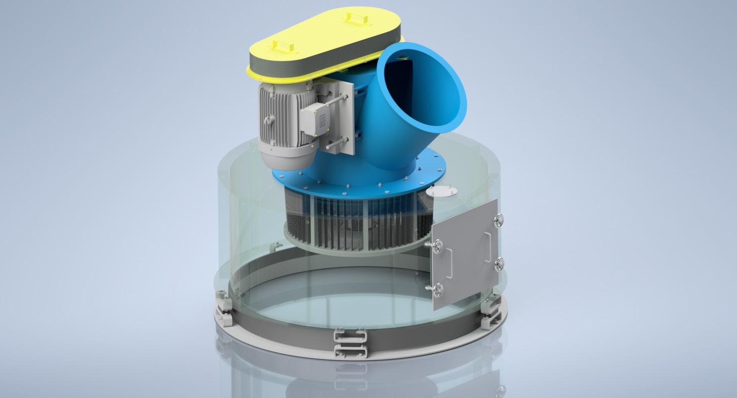
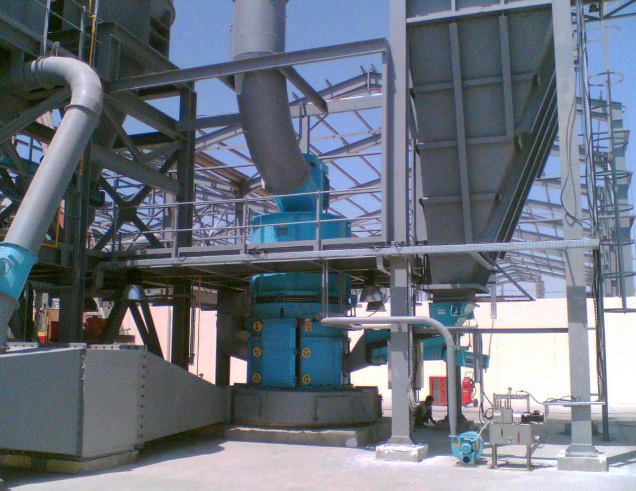


at: www.hydrocarbonengineering.com/subscribe
Subscribe online at: www.hydrocarbonengineering.com/subscribe
at: www.hydrocarbonengineering.com/subscribe
Alberto Militare, LB Technology, Italy, examines the benefits of fertilizer granulation within the agri-food, crop nutrition, and animal feed sectors.

Granulation is a technological process in which the particles of a homogeneous powder are adhered to each other for the formation of granules.
Granules are smooth, compact, simplify transport, dosing, and in general, material management.
They allow no dispersion of fine dust and no segregation of the various components.
The reasons for granulation are as follows:
n Fine dust is a nuisance.
n Granules are easy to handle.
n Granules guarantee a constancy of the composition of the mixture of components.
In the agriculture sector, granulation is used for the production of granules and/or microgranules of fertilizers rich in nutrient components for the soil.
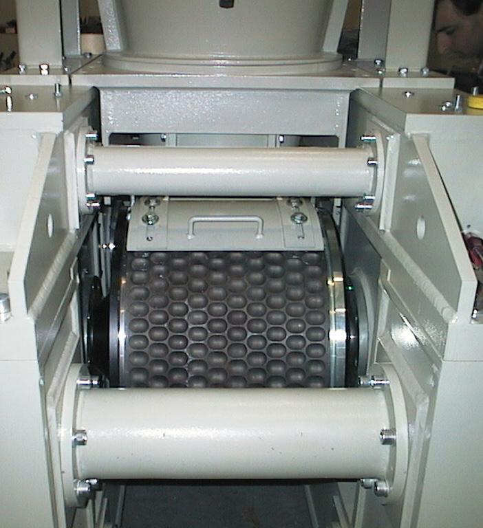
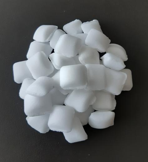
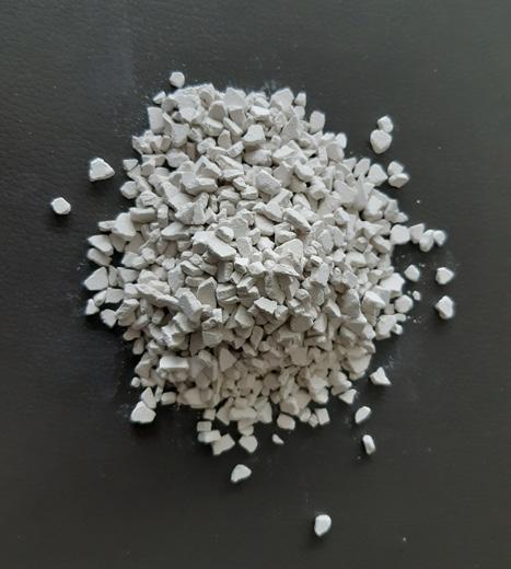
The granulation process can be divided into two large families:
Dry granulation is a process in which no liquid component is used in the formation of granules. This is done for compounds that are extremely sensitive to moisture and heat and when it is not necessary to obtain a granule of ‘spheroidal’ shape. Therefore, it is possible to use a much cheaper process than wet granulation. Since no liquid is used, the process requires compaction and densification of the finely pulverised compound to convert it into granules. It is a highly sustainable process from an economic and environmental point of view.
In dry granulation, granules are obtained by compaction of the powder, thus forming briquettes and subsequent breaking and screening of the compacted product.
Depending on the type of material treated, for proper compaction a certain degree of moisture of the material or the use of binders may be necessary.
Granules are formed under high pressure as well as the powder of the compound is aggregated using high pressure.
In wet granulation, granules are formed by the addition of a granulation liquid (binder) to dust. It is suggested for this process that it is best to obtain microgranules with size between 0.5 - 1.2 mm, to be used as micro-fertilizers in agriculture.

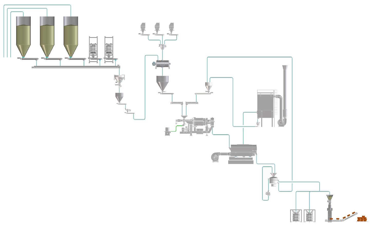
The wet granulation is used to increase the initial size of the powder with the addition of water and/or binding additives both in liquid and solid form, starting from mono-ammonium phosphate (MAP) or di-ammonium phosphate (DAP).
The microgranule sizes could be within a range of 0.5 - 1.2 mm or to 2 mm as a maximum size.
Fertilizers are critical to agriculture and include a combination of different nutrients, e.g., nitrogen, phosphorus, and potassium – or NPK fertilizers.
As with any minerals, fertilizers go through multiple processes to reach the final usable form. Granulation is part of the value chain and it is a process that increases particle size, reduces losses, and ensures greater precision in the fertilizer field applications.
Fertilizers represent for plants what food means for humans and animals. To live, plants need to absorb the nutrients that are contained in the soil but, over the time, soils tend to become impoverished, making plant nutrition increasingly difficult.
Fertilizers provide the right mixture of the primary nutrients (nitrogen, phosphorus and potassium)
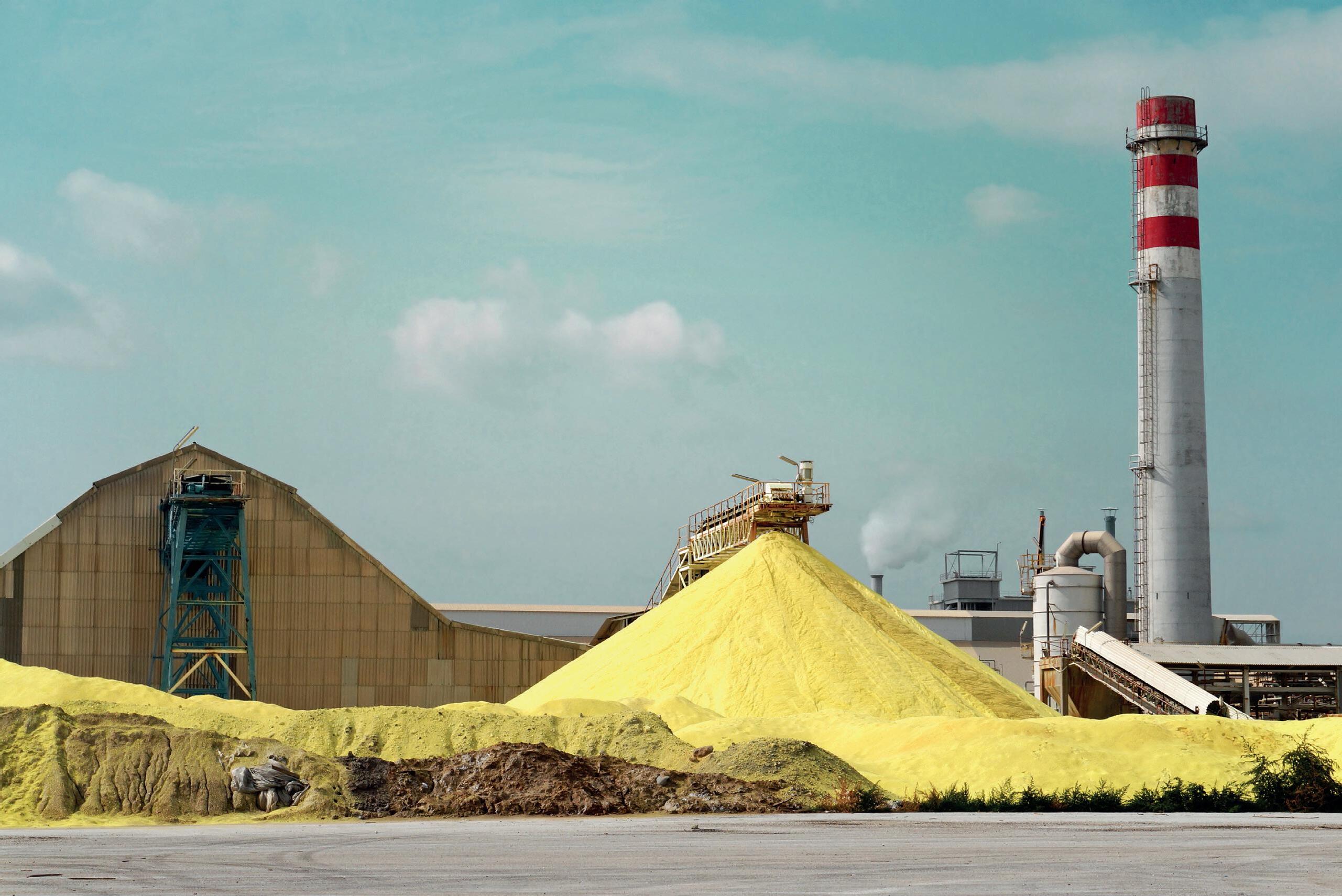

and secondary nutrients (calcium, magnesium, sulfur, etc.), allowing the preservation of soil fertility.
The distribution of fertilizers for sowing, with the use of seeders, is suitable only for mineral fertilizers.
The microgranular shape, combined with the type of machine used for distribution, ensures that the ‘4R principle’ is met: the right source, the right rate, the right time, and the right place. The advantages of microgranules and the 4R principle, plus the benefits of the right technology, are detailed in the next section of this article.
The microgranule and its best applicability in the agri-food world, intercepts a real need of the moment – precision agriculture or the so-called ‘precision nutrition’.
Having a technology that allows the targeted use of a fundamental resource in order to produce food and agricultural commodities is advantageous.
With this technology, it is possible to associate the right quantity of fertilizer and locate it at a particular time such as sowing. The two advantages are intertwined. Historically, granulation was born to be able to locate the right quantity of food at the right time associated with the phenological phase (seed that is about to germinate in the soil). This technology and the microgranules production process was born as a response to this very need.
The 4R principle is as follows:
n Right source: balanced composition of nutrients.
n Right rate: right quantity of fertilizer.
n Right time: locate it at a particular time.
n Right place: such as sowing.
The right technology is also beneficial (to make granules and to apply them).
The right dosage, at the right time, with the right technology; this is what technology, such as the LB technology, is able to offer to the operators of the fertilizers sector.
The size of the granule is important because it can provide the right quantity of food for the plant without negatively affecting its growth. It therefore provides nutrients that are totally available and easily accessible by young plants.
To use a microgranule, the product must be located together with the seed and then it is passed through the tool of the seeder that allows the distribution of the microgranule in the soil.
The role of the technology in the supply chain is providing the most suitable and sustainable technical means necessary to provide food to plants and, indirectly, to humans.
Microgranulation technology can help in this increased demand for productivity because the use of microgranule is one of the factors that contribute towards helping farmers to increase productivity per hectare.
Microgranules allow the farmers to use in a targeted manner the quantity of food that plants need, when it is needed and to limit waste. There is no waste on the one hand and no damage is done due to overfeeding or poor nutrition of the plant.
LB Technology is able to supply industrial plants and machines for both dry granulation and wet granulation and, in the latter case, both for the production of microgranules and for the production of macrogranules.
In the field of soil fertilization, the use of microgranules has significant advantages in terms of the effectiveness of the granule as a fertilizer, and in terms of eco-sustainability for the environment.
Two new lines of the LB plant for the granulation of fertilizers are successfully operating in Turkey at the Palmira factory, a company belonging to Alarko Group.
The productivity per year of the two lines is between 15 000 - 16 000 t of microgranules with dimensions between 0.5 - 1.2 mm.
The system is equipped with advanced technology, which allows automatic quality controls of the finished product and automated management of any corrections to dosages and formulas, without operator.
In addition to the production lines, the plant is equipped with an analysis, research and control laboratory with instruments of high economic value. Over 10 specialists work in the laboratory.
The realisation of the third line is planned to kick off in October 2025, and will go into production at the end of 2026, increasing productivity by 8000 t.
LB has recently signed an agreement with a US company for the supply of a microgranulation line for animal feed additives.
The line, equipped with the new HGT granulator by LB, was presented during the last Exposolidos exhibition in Spain and Powtech in Germany, and a fluid bed dryer. It will produce approximately 2 tph of microgranules with dimensions up to 2 mm.
The line will be built guaranteeing a limited environmental impact, with very low emissions into the atmosphere thanks to the use of cutting-edge, ecological and sustainable filtration systems. The new plant will start operating at the beginning of 2026.
All naturally occurring substances, if properly treated, may be granulated.
The choice of the type of granulation process is in relation to the characteristics of the materials to be treated and the use of the granule obtained.
In the field of soil fertilization, the use of microgranules has significant advantages in terms of effectiveness of the granule as fertilizer and in terms of eco-sustainability for the environment.
The advantages of using microgranules instead of macrogranules, when possible, is less fertilizer used (10 times less compared with macrogranules quantity used) and totally compliant with 4R principles.
The dry and wet granulation technologies are the present and the future of a fully sustainable fertilizer industry worldwide.

Brad Hudson, Mettler Toledo, USA, outlines key considerations when designing vehicle scales to ensure adequate corrosion protection.
Truck scales, or weighbridges, often play a critical role in the production of fertilizers and related products. By quantifying incoming raw materials and outgoing goods, the scale often plays the role of the ‘cash register’ for the operation.
A truck scale or weighbridge is a significant capital investment that should be expected to offer many years, if not decades, of operational service. Corrosion resistance is one of the key factors in the longevity of the structure and the measurement components within.
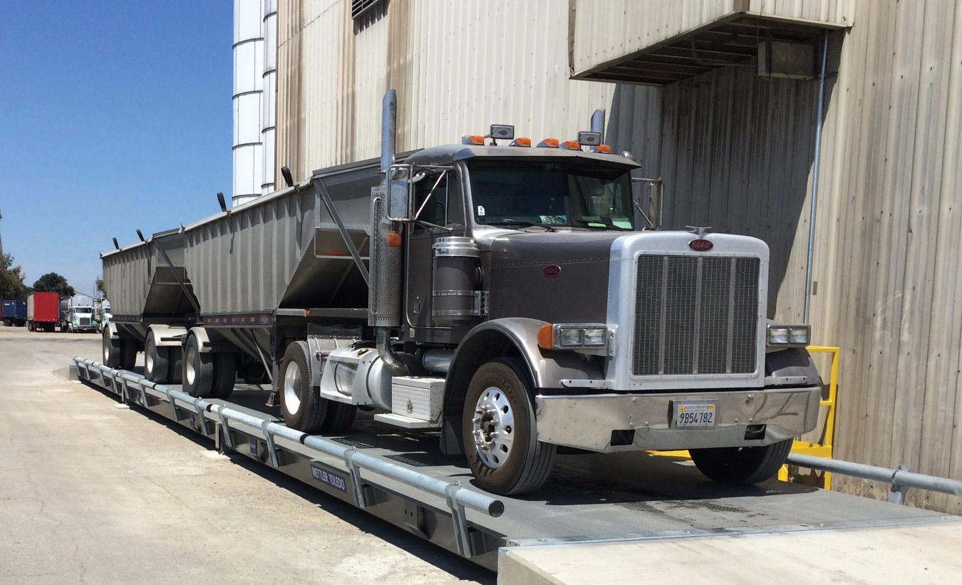
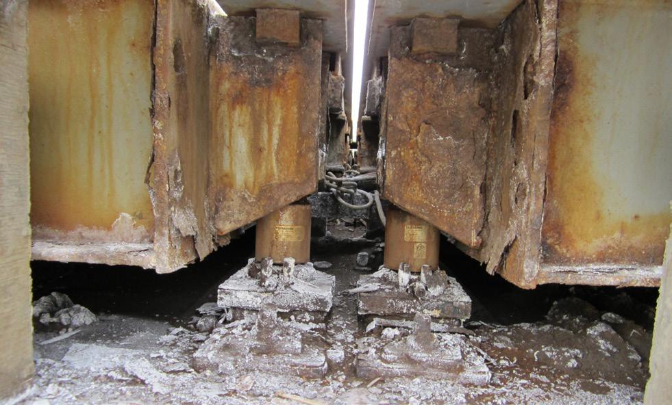
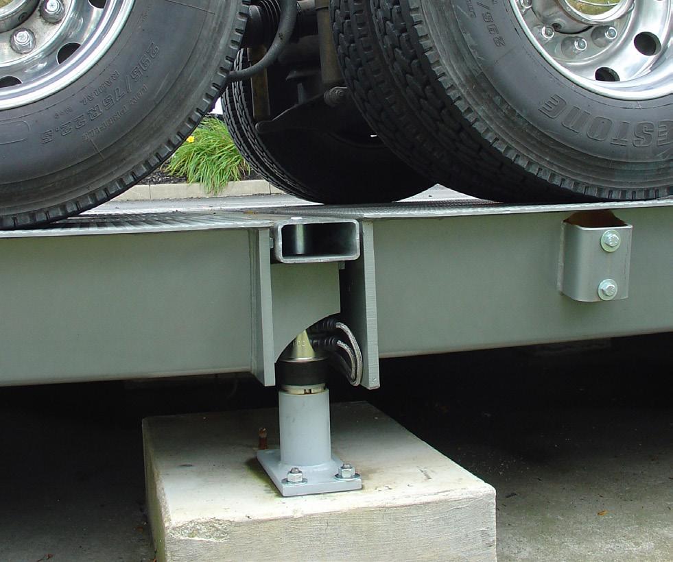

Fertilizer production can be a challenging application for the longevity of a vehicle scale, due to many corrosive materials that are employed. Acids, salts, and some gasses that are common to the industry can quickly have a detrimental effect on unprotected carbon steel. Understanding the design principles and material options available can help sites make educated decisions about their next truck scale or weighbridge to optimise the asset’s useful life.
Foundation design can be one of the first considerations for a new vehicle scale. Typical options include above ground and pit-style foundations.
Above ground installations can offer benefits to component access for serviceability and cleaning needs. The site will need to have adequate natural drainage. Above ground installations will also require approaches (ramps) with adequate space for traffic to maneuver onto and off the scale.
Pit-style foundations are often preferred for sites with limited space, or when the scale needs to be located directly adjacent to tanks or other vessels that will receive or distribute material. They do not require separate approaches and may require less space for vehicles to properly manoeuver onto the scale. However, drainage within the pit should be properly addressed with active sump pumps that are regularly inspected, tested, and cleaned. As well as this, pit depth should be adequate for service technicians to access the underside of the scale, and for cleaning needs. Confined space permitting for this work may be required at sites where hazardous materials are in-use.
In many regions, vehicle scales are available in steel deck or concrete deck options for the driving surface. Steel deck scales typically utilise a 5/16 in. or 3/8 in. deckplate, with 1/2 in. as an option from some manufacturers. A concrete deck consists of a steel pan into which concrete is poured and cured on site. Even on a concrete deck scale, the underlying steel structure is critical.
Over time, spillage of material onto the scale deck is a reality that many sites will face. Prompt cleaning of the scale is recommended in those situations to mitigate the effects of potentially corrosive materials. When selecting a weighbridge where effective cleaning is a priority, it is important to consider the design and manufacturing of the structure.
Some weighbridges are fabricated using stich welds that leave open seams between structural components. Those unwelded joints can provide an opportunity for ingress of corrosive material, or water in the case of cleaning operations and precipitation. A structure with continuous welds, leaving no gaps in the welded joints, is beneficial as it will be impervious to material and moisture ingress.
Build-up of spilled material or other debris – particularly around the load cells (weight sensors) at each corner of the weighbridge modules – is another contributor to corrosion, binding, and other issues. When selecting a weighbridge, companies must ensure that those areas are easily accessible for inspection and cleaning purposes.
The protective coating applied to the weighbridge should also be carefully analysed, especially for fertilizer operations.
A good scale provider should be able to comment on the properties of their coating and its expected resistance to materials used at the site. In recent years, providers such as Mettler Toledo, have migrated to modern epoxy-based coatings, offering better adhesion and chemical resistance over traditional paints. Multi-stage coatings are available from many manufacturers for enhanced protection, and a good manufacturer should also offer a millage spec for their standard and optional coatings.
Galvanising or metalising of the weighbridge is possible from some manufacturers, which offers significant improvements to the corrosion resistance of the structure. These options come at a considerable cost, but extending the life of the scale in especially challenging environments can prove to be a worthwhile practice.
Stainless steel weighbridges may also be an option from some manufacturers. This option is rare, and often considered cost prohibitive. However, some critical applications where especially challenging materials are being processed may want to explore such an option.
Load cells are the sensors under the scale deck that measure the load on the weighbridge. While critical to weighing accuracy, the robustness of the load cell system is also the main determining factor regarding scale reliability. Studies show that approximately 75% of truck scale or weighbridge service and repair calls are derived from malfunctions in the load cell system. The following will discuss each of the main components and what to look for.
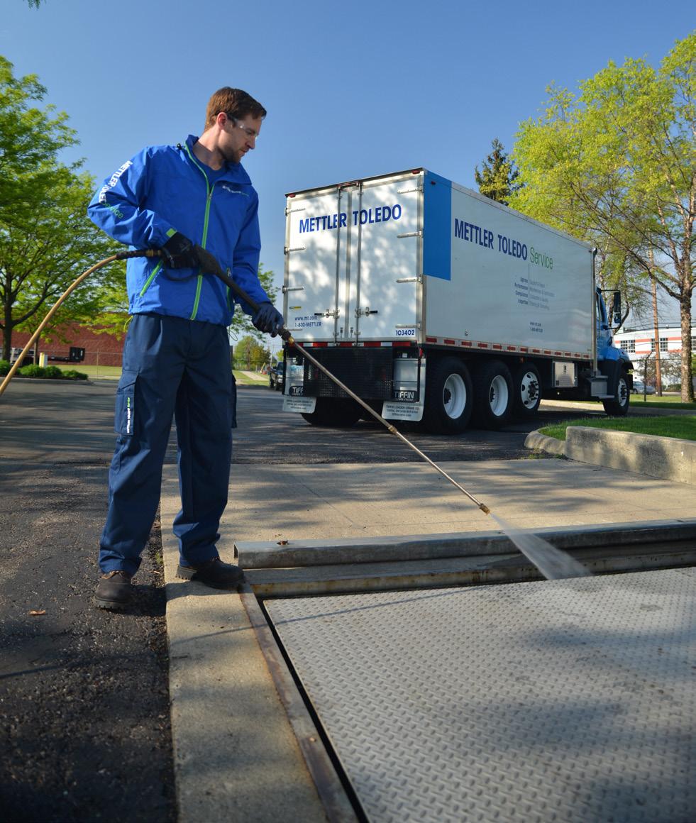
Load cells can have vertical or horizontal orientations, but most rely on a structural steel element – often a solid pin or column – to which a series of small strain gauges are attached. The deflection of the steel under load changes the electrical


A podcast series for professionals in the downstream refining, petrochemical and gas processing industries
EPISODE 1
Alan Gelder, Senior Vice President of Refining, Chemicals and Oil Markets at Wood Mackenzie, provides a review of downstream markets in 2024 and looks ahead to what 2025 may hold for the sector.
EPISODE 2
Dr Klaus Brun, Global Director of Research & Development, Ebara Elliott Energy, joins us to discuss the progress that is being made towards adapting centrifugal compressors for high-speed hydrogen compression.
EPISODE 3
Peter Davidson, CEO of the Tank Storage Association (TSA), joins us to discuss the essential role that the tank storage sector has to play in ensuring supply security and resilience, as well as in facilitating the energy transition.


Listen and subscribe here
resistance of the circuit in the strain gauge, and the electrical current output is digitised into a weight value either within each load cell, in a wiring junction box, or within the scale terminal (control unit).
Many load cells used in vehicle scales offer stainless steel enclosures that protect the sensitive internal components from the elements and potentially corrosive substances. It is important to ensure that the grade of stainless steel offers appropriate protection from the materials that may come into contact with the scale. Laser-welded enclosures have become more common to ensure a consistent hermetic seal in the load cell enclosure. Companies must also consider the ingress protection (IP) ratings of the load cells to understand the impacts of special cleaning techniques, such as high-pressure sprays.
The integrity of the load cell enclosure is paramount to protecting the service life of those components. Even a hidden pin-hole breach to the protective housing can allow ingress of atmospheric moisture and other contaminants, with the potential to eventually foul the sensitive internal electronics and eventually cause load cell failure. For the ultimate protection, some advanced load cells, such as POWERCELL® PDX®, offer breach detection systems that will immediately alert the scale operator to an enclosure breach. This allows proactive inspection
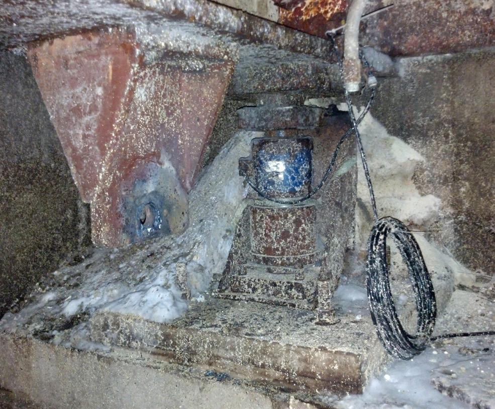
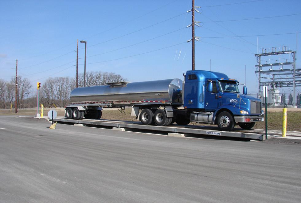
and service to be scheduled conveniently, prior to a potentially disruptive component failure.
Load cells are connected using a series of cables that ultimately reach the scalehouse or other location of the scale terminal. The cables and their connections are critical to the reliability of the system. Some manufacturers offer cables with standard or optional stainless steel braided sheathing for protection from debris, snow shovels, rodents, and other physical damage. Many load cells use integral cables, which cannot be detached from the cell, meaning a cable failure necessitates load cell replacement and scale recalibration. Some load cell systems offer detachable cables which can streamline repairs, but buyers should ensure that the connection type, such as a locking glass-to-metal seal, is suitable for challenging applications.
Junction boxes are a common potential failure point that deserve added attention from scale buyers using corrosive materials. These boxes house the bare wire connections from each load cell and combine those signals before they connect back to the scale terminal. Despite often being equipped with thick seals and cable glands, junction boxes are routinely opened during scale service events, including regular calibrations and any load cell replacements. Over time, moisture and other debris can enter the junction box and degrade the sensitive connections and circuitry within. Due to the commonality of this scenario, junction boxes are considered to be the main cause of scale downtime.
The scale installer may aim to locate the junction boxes for easy access by service technicians. However, the scale owner should ensure that the junction boxes are mounted in locations where they will avoid contact with standing or draining water, spilled material from the scale deck, or debris that may periodically build up alongside the scale.
To avoid those challenges entirely, some modern load cell systems are available with a cell-to-cell network that eliminates junction boxes. Sites that experience heavy precipitation, challenges with drainage, or corrosive debris should consider the advantages of eliminating those failure-prone components.
Corrosion is a long-term concern for many types of industrial equipment, and truck scales are no exception. New installations should consider the impacts of the scale foundation for effective drainage and debris removal. To maximise the service life and reliability of a truck scale, buyers should be conscious of the design and manufacturing principles of the weighbridge, seeking out continuous welds, designs that shed moisture and debris, and offer suitable factory-applied protective coatings.
The scale’s load cells should offer environmental protections in the form of high-quality stainless steel enclosures. The load cell cables should be of high-quality and ideally offer stainless steel braided sheathing for longevity. Finally, junction boxes should be mounted in locations that minimise contact and exposure to moisture and debris, or alternatively, consider a load cell network that eliminates junction boxes altogether.
While no scale will last forever, some will last considerably longer than others in fertilizer applications. By being conscious of those fundamentals, scale owners can maximise the service life of their assets, while minimising downtime and service costs for many years to come.

Brett Binnekade, Bagtech International, South Africa, discusses predictive maintenance with artificial intelligence (AI) in fertilizer blending and bagging plants, and how to make modern fertilizer plants more efficient and reliable.
Fertilizer blending and bagging plants involve multiple stages including raw material handling, blending, bagging, and distribution. Motors, gearboxes, conveyors, weighing devices, mixers, and packaging lines must work in perfect harmony to meet precise nutrient formulations and packaging standards. Even minor mechanical issues can stall production, disrupt the supply chain, and jeopardise product uniformity. Many lines are running a ‘just-in-time’ model with zero stock holding, raising the stakes even higher.
Historically, two basic maintenance approaches have prevailed. Firstly, reactive maintenance where repairs occur after failure. This approach can lead to extended downtime and safety risks, especially when a single component’s breakdown causes a production line halt. Then secondly, preventive maintenance, which is based on scheduled checks or fixed usage intervals. It pre-empts
some failures but can cause unnecessary part replacements and downtime if intervals are set too conservatively. Conversely, if intervals are too long, unexpected failures may still occur.
Given the tight operational window in fertilizer production, particularly during peak agriculture seasons, unplanned downtime or suboptimal maintenance scheduling can be financially crippling.
Predictive maintenance uses real-time and historical data, alongside artificial intelligence (AI) and machine learning models, to predict potential equipment failures before they happen. Instead of relying on rigid timelines, it relies on condition-based insights derived from:
n Sensor data: vibration, temperature, acoustics, and other parameters continuously measure equipment health.
n Operational data: current and voltage signals from variable speed drives (VSDs), plus load and throughput information.
n Predictive algorithms: advanced analytics detect anomalies and forecast remaining useful life of critical components.
By identifying subtle performance deviations, predictive maintenance empowers operators to service machinery at precisely the right time.
Predictive maintenance aligns well with fertilizer plants for several reasons, including the following:
n Reduced downtime: anticipating problems means scheduling repairs during planned outages, mitigating abrupt production stops.
n Improved equipment utilisation: components are replaced only when necessary, extending their operational life.
n Consistent quality: optimally functioning mixers, weighers, and bagging lines maintain precise nutrient ratios and package weights.
n Cost savings: lower parts consumption, fewer emergency repairs, and stable production schedules all drive down costs.
n Enhanced safety: early fault detection mitigates risks associated with running failing machinery.
Condition monitoring has existed in some form for decades. Yet AI-based predictive maintenance elevates its capabilities significantly. Through algorithms such as neural networks or support vector machines, large volumes of sensor and operational data can be continuously analysed to detect evolving failure patterns. AI can catch early warning signals that may be too subtle for standard threshold-based monitoring systems.
A successful predictive maintenance system hinges on robust data pipelines:
n Sensor and drive data collection: fertilizer plants deploy sensors measuring vibration, temperature, and pressure on motors, gearboxes, and conveyors. Additionally, Bagtech collects data directly from VSDs, monitoring real-time current and voltage trends that can reveal patterns of motor load, electrical spikes, or inefficiencies.
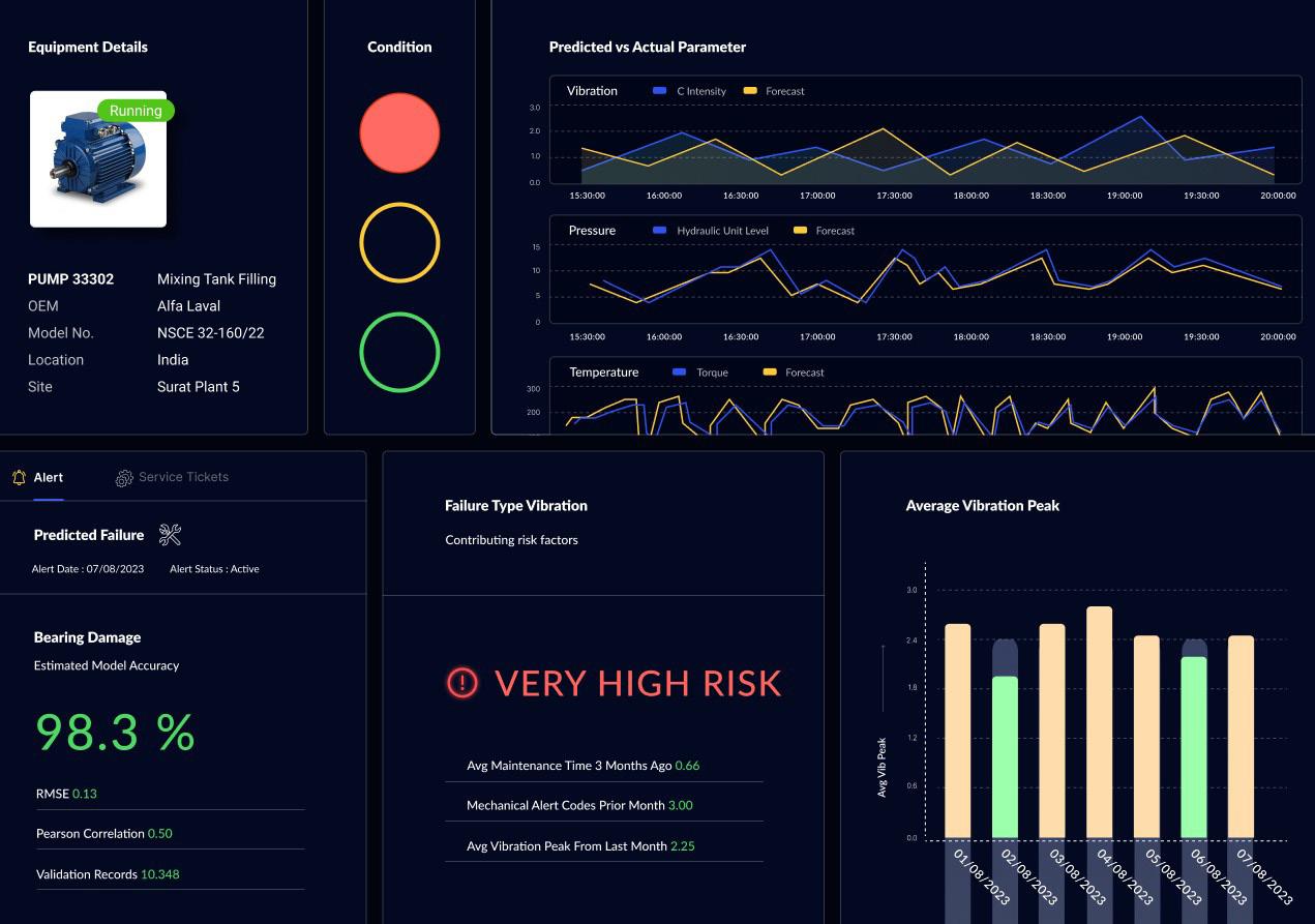
n Data transmission and storage: modern plants often rely on programmable logic controllers (PLCs) and supervisory control and data acquisition (SCADA). These systems transmit sensor and drive data to databases or cloud platforms for processing.
n Machine learning models: historical data labelled with past failure modes trains the models, enabling them to recognise symptoms of future failures. The models generate alerts or recommendations based on trends that deviate from normal baselines.
Despite the promise of AI, operators must address environmental hurdles:
n Dust and corrosion: fertilizers are often hygroscopic and corrosive. Sensors and equipment must be
ruggedised, and frequent cleaning or calibration may be necessary.
n Variable operating conditions: blending different fertilizer grades changes mechanical loads and requires the AI models to adapt to varying operating states.
n Legacy equipment: integrating new sensors and data-gathering technologies into older machinery can be complex. Wireless Industrial Internet of Things (IIoT) solutions can ease this process, but consistent connectivity must be ensured.
Research and development priorities
Significant strides have been made in combining domain expertise with digital solutions. The predictive maintenance strategies hinge on:
n Modular sensor kits: easily deployed vibration, temperature, and other sensors on critical blending and bagging components.
n Drive-based data: leveraging current, voltage, torque, and speed signals from variable speed drives to identify anomalies without installing additional, dedicated sensors in certain areas.
n AI models tailored to fertilizer operations: years of fertilizer process knowledge inform its predictive algorithms, making them highly relevant to blending, bagging, and material handling steps.
n User-friendly dashboards: real-time alerts, condition analytics, and maintenance schedules are centrally displayed, providing straightforward insights for operators.
In a pilot project targeting key blending motors, Bagtech utilised both vibration sensors and VSD data. By correlating current and voltage trends with vibration signatures, the system identified early-stage bearing wear and alignment issues. When deviations appeared in motor current draw at certain load points, the AI module cross-referenced vibration data to confirm potential faults. Maintenance personnel received timely alerts, enabling them to replace bearings before a catastrophic breakdown. This proactive intervention improved the blender’s uptime, product consistency, and reduced repair expenses.
Sensor and data strategy
While dedicated sensors remain crucial for detailed vibration and temperature monitoring, companies can maximise existing
plant systems by mining VSD data. This dual approach keeps hardware costs manageable and accelerates installation:
n Identify critical assets: motors driving conveyors, mixers, and bagging machines are prime targets, along with gearboxes and high-wear components.
n Sensor deployment: for components showing frequent failure or extreme operational conditions, direct vibration or temperature sensors provide granular data.
n VSD integration: the systems read current, voltage, and torque signals from drives, using them to detect changes that suggest mechanical or electrical stress.
Connectivity and processing
Operators can choose a cloud-based approach, ideal for large, geographically dispersed operations, or an edge-based approach for real-time results on-site. In either case, the data flows seamlessly into the analytics engine, where AI models detect anomalies.
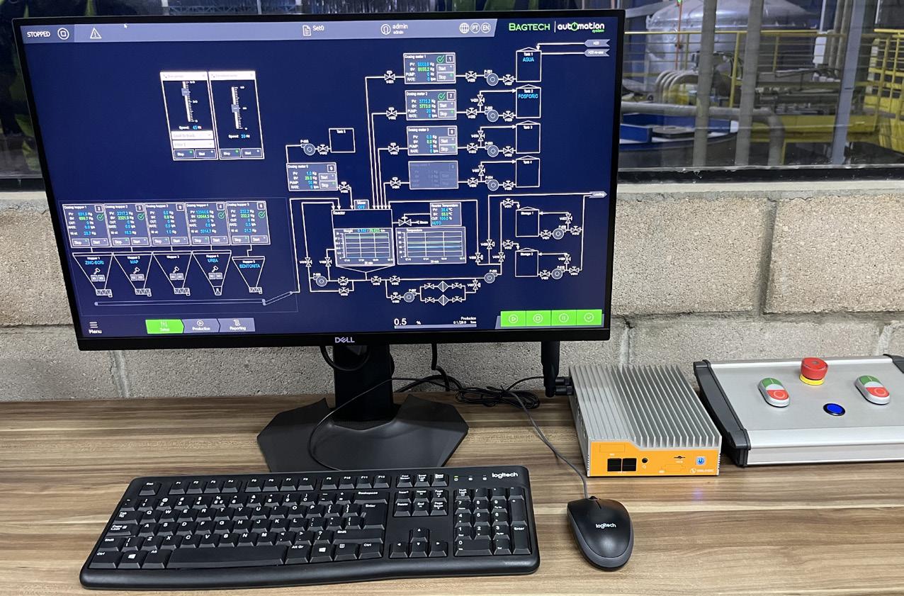
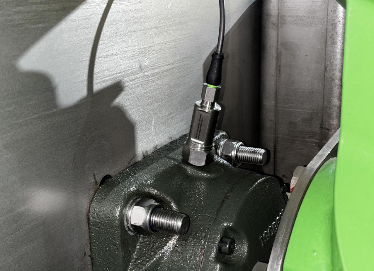
Key considerations:
n Network reliability: fertilizer plants often operate in harsh or remote environments, making robust networking crucial.
n Scalable architecture: as more equipment is added or new data streams become available, the system must scale without performance issues.
n Data security: managing intellectual property, operational integrity, and cyber-security risks is paramount, especially when external networks or cloud solutions are involved.
Algorithm development
Bagtech starts with supervised learning, using historical records of failures to label data. Over time, semi-supervised or unsupervised methods can uncover subtle, previously unidentified fault indicators. Regular retraining ensures models remain current as operational conditions shift, new fertilizer grades are processed, or equipment undergoes modifications.
Workforce training
Predictive maintenance solutions only succeed if maintenance staff trust and understand the system’s insights. Training resources can be provided to help operators:
n Interpret alerts: recognise the severity of an alert and understand recommended actions.
n Perform proactive repairs: conduct interventions ahead of failures, extending component life-cycles and preventing line stoppages.
n Document outcomes: input feedback into the system, refining machine learning models with each real-world event.
Minimising downtime
Predictive maintenance allows operators to schedule interventions during planned breaks or off-peak production periods. The company’s implementations have demonstrated up to a 30% reduction in unplanned outages, enabling manufacturers to meet demanding production schedules more reliably.
Optimising maintenance costs
Cost savings manifest in several ways including fewer emergency repairs, decreased spare-part inventory, and improved labour allocation. When maintenance is driven by real-time conditions, plants avoid replacing components prematurely or missing the early signs of imminent failure. Depending on plant size and complexity, total maintenance expenses can drop by 15 - 30%.
Maintaining quality and safety
Blending inaccuracies can occur if materials are fed at inconsistent rates due to motor or gearbox stress, product build-up or blockages. Detecting such irregularities early stabilises production, preserving the precise nutrient formulations demanded by modern agriculture. Additionally, preventing equipment failure helps maintain a
safer working environment, aligning with strict safety and environmental regulations.
Strengthening competitive position
Predictive maintenance translates into a more consistent, high-quality product output and fewer supply chain disruptions, both essential for customer satisfaction. In a market where fertilizer supply timing can affect crop yields, reliability becomes a formidable competitive advantage.
Digital twins and prescriptive maintenance
A digital twin, a virtual replica of physical equipment, could integrate sensor and VSD data with physics-based models to simulate machine behaviour. This enables advanced ‘what-if’ analysis: if a mixer motor shows impending wear, operators can model the impact of slowing production throughput or adjusting blending sequences until repairs are scheduled. As AI techniques evolve, prescriptive maintenance will suggest optimal maintenance windows and detail cost implications or production risks.
Augmented reality (AR) and connected workers
Maintenance personnel could someday use AR headsets to receive real-time instructions, visualise hidden components, and share live equipment data with remote experts. These capabilities reduce repair times and errors, particularly for intricate blending towers or large-scale bagging lines.
Integration across the value chain
Predictive maintenance data could also inform upstream and downstream activities. For example, producers might coordinate shipping with distributors based on predicted plant throughput. This could further optimise fertilizer supply chains, improving on-time delivery and reducing storage or handling costs.
As global demand for fertilizer grows, balancing efficiency, reliability, and product quality becomes ever more critical. Predictive maintenance driven by AI, powered by robust data from sensors and variable speed drives, offers a transformative approach. Fertilizer plants that implement these strategies can reduce downtime, trim operational costs, and consistently deliver products that meet stringent nutrient specifications. Through real-time condition monitoring, actionable analytics, and well-prepared maintenance teams, fertilizer manufacturers can seize new efficiencies and opportunities. In a climate where achieving maximum throughput and reliability is paramount, predictive maintenance stands out as both an operational advantage and a strategic imperative. By embracing AI-powered solutions, fertilizer blending and bagging plants can secure their future in an increasingly demanding agricultural landscape, one where data and technology converge to optimise productivity and drive sustainable growth.


Kyle Langley, Vortex Global, UK, considers methods to mitigate against the risks posed by dust accumulation.
Dust explosions pose a significant risk in dry bulk processing industries, yet they are often underestimated. With catastrophic consequences that can include destruction of property, injury, and even loss of life, effectively controlling dust emissions is a necessity, not an option.
At the heart of this challenge lies proper material flow equipment, specifically dust-tight equipment. This equipment is essential for ensuring operational safety, minimising environmental impact, and adhering to
international regulations. This article will explore the role of dust-tight equipment, the risks posed by dust accumulation, and how optimised equipment designs help mitigate dust explosions.
Before diving into viable solutions, it is essential to first understand the root causes of the problem. Dust explosions are categorised as either primary or secondary explosions, and each type has unique risks and consequences that industries must address.
Primary dust explosions occur within confined spaces, such as equipment, silos, or processing machinery. These explosions
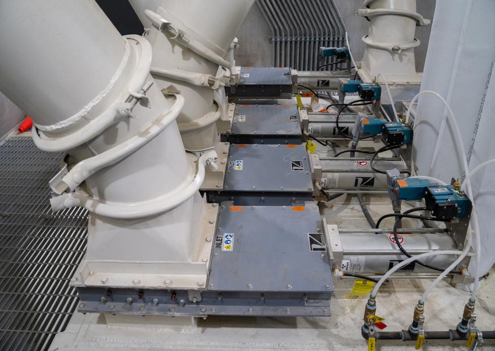
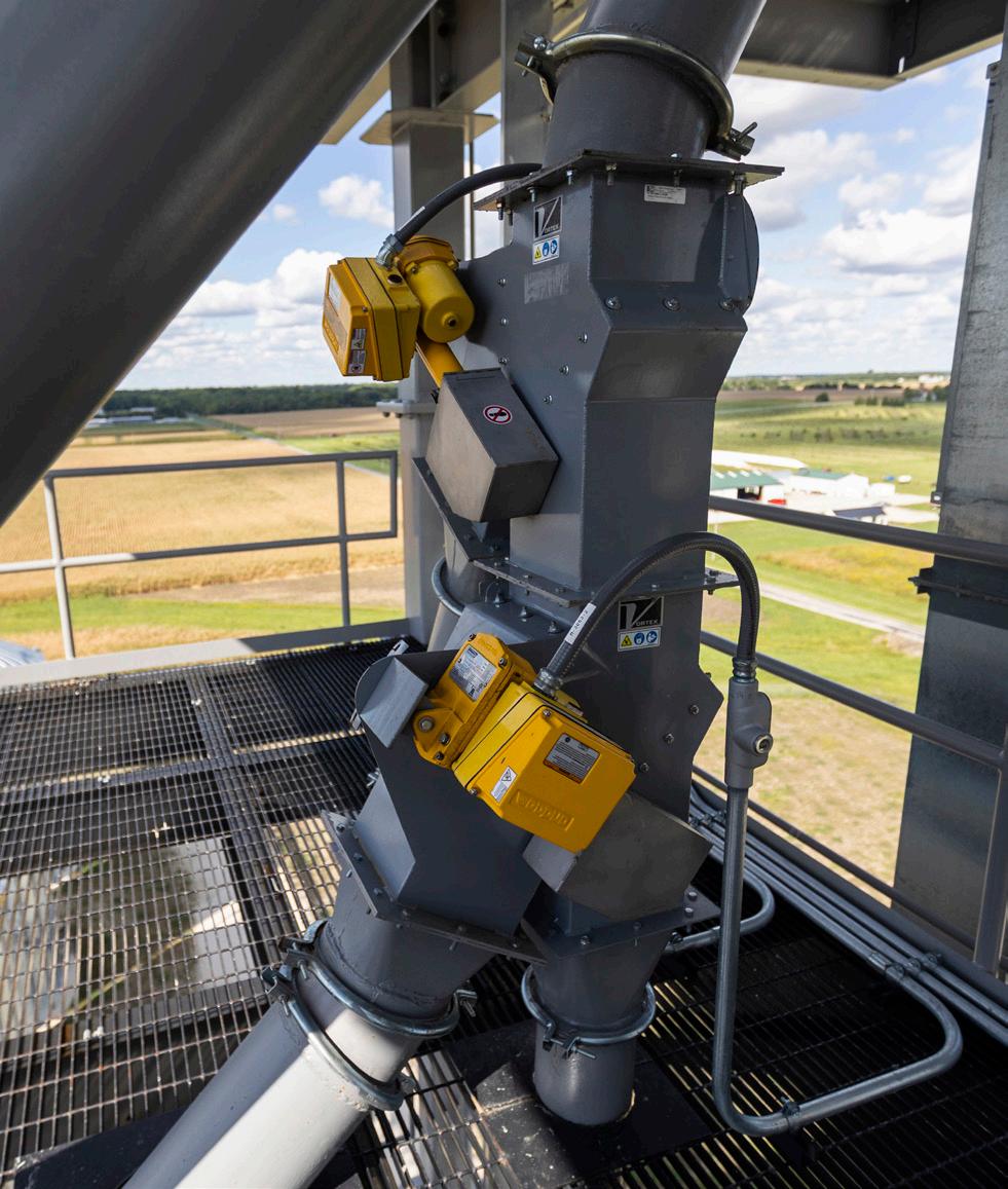
happen when combustible dust is ignited within such enclosures. Dangerous, primary explosions are often managed through engineering controls, such as pressure relief systems that vent the explosion safely to the external environment. This minimises the potential damage to equipment and injuries to personnel. However, even with these measures, the potential for escalation remains if dust is not properly controlled.
Secondary dust explosions are far more hazardous and catastrophic. These occur when settled or accumulated dust inside a facility is disturbed, and becomes airborne due to a primary explosion. The suspended dust cloud can then ignite, leading to a chain reaction of explosions that spread rapidly throughout the workplace. This widespread devastation can obliterate entire facilities, cause severe injuries, or loss of life.
Combustible dust remains a serious threat in industrial environments, as demonstrated by both historic and recent disasters. The 2008 Imperial Sugar refinery explosion in Georgia, US, serves as a sobering example. Caused by an accumulation of sugar dust, the blast resulted in 14 deaths and 36 injuries. Investigators attributed the tragedy to poor housekeeping and ineffective dust control, declaring the incident entirely preventable.
Similarly, the 2010 Upper Big Branch Mine disaster in West Virginia, US, was triggered by a coal dust explosion, which claimed the lives of 29 miners. Investigations later revealed inadequate ventilation and blatant safety violations as primary factors behind the catastrophe.
In 2016, a dust explosion occurred in a fertilizer blending facility in China, caused by the ignition of fine dust particles during the mixing process. The explosion resulted in injuries and severe damage to the facility. This incident highlights the risks associated with handling fine, dry fertilizer materials.
More recently, on 4 October 2024, an explosion at the Hanford Grain Co. in California, US, injured two workers. Preliminary findings suggest that highly flammable grain dust played a significant role in the incident.
These events underscore the ongoing dangers of combustible dust and highlight the urgent need for stringent safety protocols, proper housekeeping, and well-maintained equipment. By prioritising proactive safety measures, industrial operations can prevent such avoidable tragedies and protect their workforce from harm.
The fertilizer industry is particularly vulnerable to dust explosions due to the fine particulate matter generated during production and handling. Like agriculture, food production, chemicals, plastics, metals, pharmaceuticals, and textiles, the fertilizer sector faces significant risks when dust builds up over time. These conditions can create the potential for catastrophic incidents if not effectively managed.
For companies in these industries, taking a proactive approach to controlling dust emissions is not just a regulatory requirement, it is a necessity for ensuring workplace safety. Utilising dust tight equipment, implementing proper housekeeping practices, installing effective dust collection systems, and conducting regular risk assessments are critical steps toward mitigating the risk of both primary and secondary explosions. By addressing these hazards early and thoroughly, businesses can create safer working environments, protect their employees, and avoid the consequences of a dust explosion.
Why dust-tight equipment is critical
Dust-tight equipment is essential in dry bulk systems to regulate material flow, prevent fugitive dust, and ensure smooth, efficient operations. Whether handling fertilizer, grain, sugar, cement, or metal powders, industrial processes rely on equipment, such as valves and conveyors, to transfer and process bulk materials safely. However, equipment failures – particularly in seals or structural integrity – can lead to significant safety and operational risks, allowing dust to escape into the environment.
Airborne dust is a serious hazard when exposed to ignition sources like static electricity, equipment sparks, or hot temperatures. Dust explosions are a well-known risk in industries handling fine particles, and even small leaks in faulty seals or compromised equipment can contribute to unsafe working conditions.
The root of the issue often lies in traditional equipment designs and materials. Many standard components, including valves and seals, were developed for liquids or gases, and are not optimised for abrasive dry particulates. Friction, impact, and wear from solid materials cause these components to degrade prematurely, leading to leaks and operational inefficiencies. Modern dust-tight equipment addresses these challenges through advanced engineering and materials.
Dust-tight equipment is specifically designed to handle the unique challenges posed by dry bulk materials. With durable materials and precision design, these systems ensure both safety and efficiency in industrial operations. Key features of modern dust-tight equipment include:
n Durable sealing technology: high-performance equipment integrates seals made from abrasion-resistant composite materials that can withstand constant friction and impact from abrasive particles. These heavy-duty seals significantly reduce the risk of leaks and minimise maintenance needs.
n Reinforced structural integrity: dust-tight equipment, such as reinforced valves and conveyors, are built to endure demanding industrial environments. Robust housings and components maintain consistent performance even with abrasive/corrosive materials like fertilizer, cement, silica, or metal powders.
n Precision manufacturing: the best equipment is engineered with extremely tight tolerances to prevent dust from escaping through gaps or misalignments. This precision improves overall durability and reliability, reducing downtime caused by leaks or mechanical failures.
n Ignition prevention: dust-tight equipment often includes ATEX-rated valves and components designed to prevent sparking during operation. Non-sparking materials and mechanisms are employed to eliminate ignition risks, ensuring maximum safety in environments where dust explosions are a major concern.
n Integrated dust collection systems: many modern systems incorporate dust collection technologies to capture escaped particulates. This ensures cleaner air quality, safer workspaces, and compliance with safety standards.
n Improved efficiency: by maintaining strong seals and containing materials effectively, dust-tight equipment
reduces the need for clean-up, maintenance, and system downtime. This streamlines operations and translates into long-term cost savings.
n Compliance with industry standards: advanced equipment can be designed to meet strict regulations, including OSHA air quality standards and ATEX standards for dust explosion prevention. Businesses can ensure legal compliance, while safeguarding workers and facilities.
Dust-tight equipment offers significant advancement for industries handling dry bulk materials. By addressing the limitations of traditional designs and mitigating risks associated with dust leakage, these systems improve operational safety, efficiency, and reliability. For any industry working with fine particulates, investing in modern dust-tight components is a critical step toward ensuring productivity, safety, and regulatory compliance.
Safety standards are essential in regulating environments prone to explosive dust, ensuring the safety of workers and facilities worldwide. Different countries and regions enforce specific standards to address these hazards. Three prominent systems govern these industries:
The NFPA (US) establishes guidelines to prevent fires and dust explosions in workplaces where combustible dust is present.
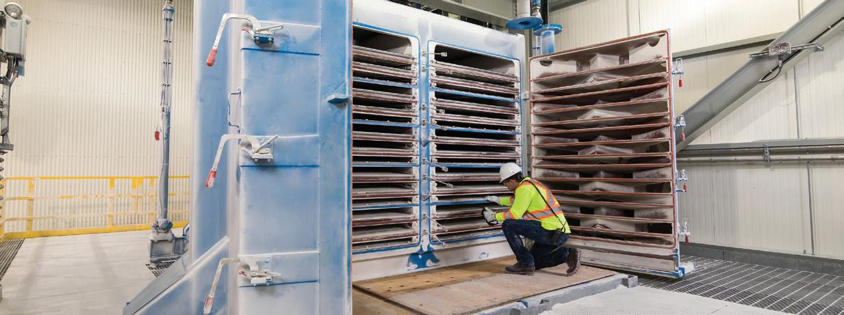
High volume offering for specific applications like fertilizer, minerals and grain.
Configuration features increased flow inlet plenum(s), more spacing between screen decks and deepened discharge doors.
Models with increased screen area and screen deck slope also available.
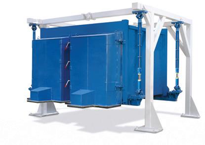
Key standards, such as NFPA 654 and NFPA 484, outline safety practices for industries handling potentially hazardous materials.
According to NFPA, dust particles smaller than 420 µm are considered hazardous, as they can ignite when dispersed into the air under the right conditions. Critical safety practices include conducting regular dust hazard analyses (DHAs) to identify and assess potential risks. Facilities must address these risks through improved equipment design, proper housekeeping, ventilation systems, and operational controls that minimise ignition sources.
The NEC (US), maintained by the NFPA, provides guidelines for electrical installations in hazardous environments, including areas with explosive dust. NEC Articles 500 - 506 define hazardous locations and classify them into classes, divisions, and groups based on the type of material and the likelihood of the hazard being present.
For combustible dust environments, NEC specifies Class II locations, further divided into Division 1 (where hazardous dust is likely, during normal operation) and Division 2 (where it may only be present under abnormal conditions). Proper selection and installation of electrical equipment certified for these classifications are critical to reducing ignition risks.
The ATEX directive (2014/34/EU) lays out stringent safety requirements for equipment used in explosive dust atmospheres across the European Union (EU). This directive is unique in its comprehensive focus, as it not only applies to electrical equipment but also to mechanical components, such as valves with moving parts, ensuring they meet dust-ignition protection standards.

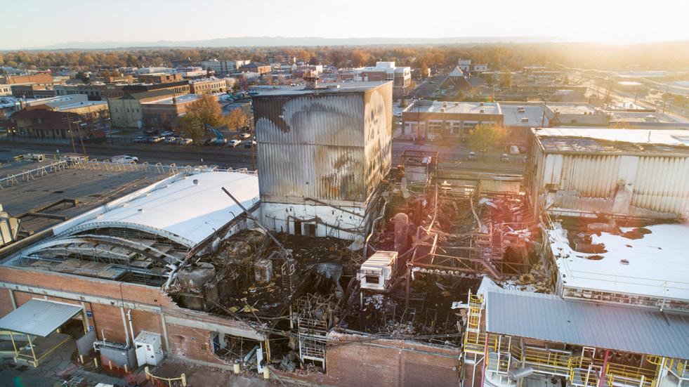
The ATEX system divides hazardous dust areas into three zones – 20, 21, and 22 – based on the frequency and duration of explosive dust presence. Each zone requires specific levels of protection and compliance. Manufacturers must ensure that the equipment used in these zones meets the required safety standards to prevent accidents and maintain operational safety.
As a provider of dry bulk handling equipment, Vortex Global ensures safety by designing dust-tight equipment capable of meeting international standards. Its equipment can be designed for use in ATEX zones 20, 21, and 22, and can be fitted with controls rated for a variety of NEC requirements, ensuring comprehensive compliance with both US and European safety regulations.
The company's equipment utilises advanced materials and engineering techniques to minimise ignition risks, while maintaining operational efficiency. By aligning with NEC and ATEX standards, Vortex helps industries safely handle combustible materials, providing reliable solutions for hazardous environments.
Preventing dust explosions requires a multi-faceted approach, combining equipment upgrades with workplace policies. Below are actionable steps companies can take to reduce risks effectively.
Perform an in-depth assessment to identify dust explosion vulnerabilities. The key areas to examine during this analysis are as follows:
n Identify materials with combustible properties.
n Locate areas prone to dust build-up, including hidden spaces.
n Ensure proper containment for processes generating airborne dust.
n Evaluate potential ignition sources in the facility.
n Assess ventilation systems’ capability to control dust dispersion.
Efficient dust collection systems can complement dust-tight components. Cyclone separators, baghouses, or electrostatic precipitators effectively reduce airborne particulates in manufacturing facilities.
Companies can consider replacing outdated equipment with models engineered to be dust-tight to the atmosphere, alongside opting for smart systems that provide remote monitoring and feedback on equipment integrity.
Proper maintenance, including regular inspections and cleaning of surfaces, equipment, and collection systems, prevents dust accumulation and ensures consistent valve performance, which helps companies mitigate against the risk of dust-related explosions.
Dust explosions remain a persistent challenge for industries worldwide, but advancements in dust control systems and equipment bring tremendous progress. By prioritising equipment innovations and adhering to international safety standards, companies can mitigate the devastating risks associated with fugitive dust.

Johannes Poth, Integrated Global Services (IGS), Germany, explains how to manage the occurrence of hot spots in primary reformers at fertilizer plants.
Hot spots in primary reformers represent a challenging and potentially costly maintenance issue for fertilizer processing plants. These localised areas of excessive temperature not only threaten structural integrity and operational continuity but can also lead to substantial economic losses through forced shutdowns. This article discusses common causes of hot spots, inspection methods, and how to fix a hot spot on a live fired heater, with recent case studies.
Primary reformers are critical components in ammonia production, where maintaining optimal temperature distribution is essential for both operational efficiency and equipment longevity. Hot spots typically manifest in reformers because the refractory lining has become compromised. Refractory linings are insulating and minimise heat loss, making them essential to retaining the high-temperature environment.
Refractory maintenance and repairs are typically undertaken during planned shutdowns. If refractory failure results in an unplanned shutdown, it can cost plants more than US$1 million per day in lost production.
The two most common root causes of hot spots are often refractory anchor failure or premature ageing of the refractory itself due to localised flame impingement from burner operations.
Refractory anchor failure often occurs due to corrosion of the welded joint between the anchor and the external steel shell of the fired heater. This failure mechanism typically involves:
n Hot flue gases penetrating through the refractory lining.
n Condensation of these gases upon reaching the cooler shell.
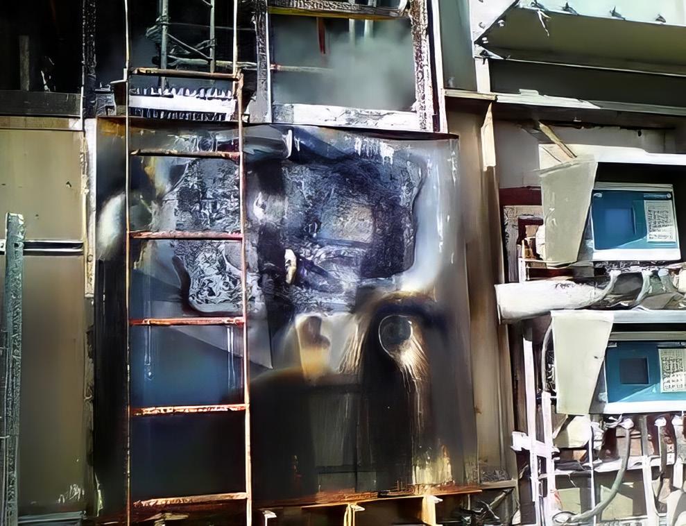
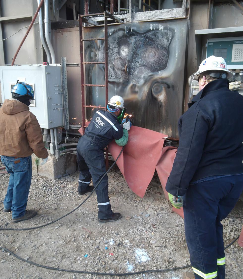
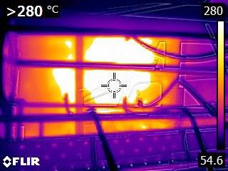
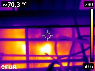
n Rapid oxidation or corrosion of the weakest point, which is usually the weld.
Once the anchor support is compromised, individual refractory components such as blankets or modules can fall away, exposing the metal shell. This creates a domino effect, leading to the failure of adjacent refractory lining.
Unless specifically designed, flame impingement may cause localised areas of premature failure of the refractory, leading to loss of insulation and hot spot formation.
Hot spots can trigger interconnected problems that severely impact operational efficiency, structural integrity and equipment longevity.
Often the first sign of refractory failure is a hot spot on the external steel shell since direct observation of the problem area is not possible. Integrated Global Services (IGS) has designed and developed a Cetek® Lancescope TM fired heater inspection tool, which allows the undertaking of an internal furnace inspection to determine the scope of the problem, often avoiding an expensive shutdown of the heater.
The hot inspection system uses a digital camera system, which provides clear, detailed images of problem areas up to 3000°F (1650°C). The furnace inspection system can be inserted into openings as small as 3 in. (7.62 cm) and reach up to 20 ft (6 m). In applications below 1000°F (540°C), the heater inspection system provides illumination via a high-temperature light source for optimum clarity. The benefits of performing a hot inspection include:
n Performed while the unit is in operation.
n Provides insight into production availability.
n Identifies damage in early stages.
n Allows for a planned repair schedule.
n Reduces maintenance costs.
n Minimises repair downtime.
n Maximises production.
Preventative maintenance is always recommended, however, if a hot spot does occur, there are several options to consider. One option is to interrupt production to take the asset offline and carry out conventional repairs. Alternatively, the furnace can continue to run at reduced performance until the next planned turnaround. However, this could exacerbate any existing damage.
Alternatively, there is the option of an online refractory repair service, such as the one that is offered by Hot-tek TM , where there is no need to bring the heater off-line and production will not be interrupted or capacity limited.
A team of refractory technicians can be mobilised at short notice and the repair involves creating minimal access point openings to insert specially designed components and repair material, delivering a semi-permanent repair lasting at least until the next turnaround.
A leading fertilizer manufacturer in Qatar recently faced a critical hot spot issue in its third ammonia production train’s reformer duct area. The situation was particularly challenging as initial repair attempts had failed. The original repair strategy of welding a patch plate proved insufficient, with subsequent cracking occurring at the interface between the substrate and the new alloy plate.
The plant could repair the hot spot offline by isolating the train, but that option would prove costly. The plant would have faced a minimum two-week shutdown.
The economic impact of avoiding such a shutdown is substantial. Another alternative would be to repair the hot spot on a live reformer during its normal operation. This type of repair requires expertise and equipment not typically possessed by general contractors.
As a result, the plant opted for Hot-tek hot refractory repair (HRR) technology, which enabled repairs to be safely completed during normal operations, eliminating the need for a costly shutdown. The repair was executed over nine shifts while maintaining full production capacity.
The plant manager said that the entire plant management witnessed the installation process, appreciating the innovative approach that averted a potential shutdown. The key outcomes included:
n Successful repair without operational interruption.
n Extension of the maintenance window by one year.
n Improved refractory performance post-repair.
n Significant cost savings through shutdown avoidance.
At a leading mining and metals company in Saudi Arabia, a time-sensitive situation emerged when its ammonia
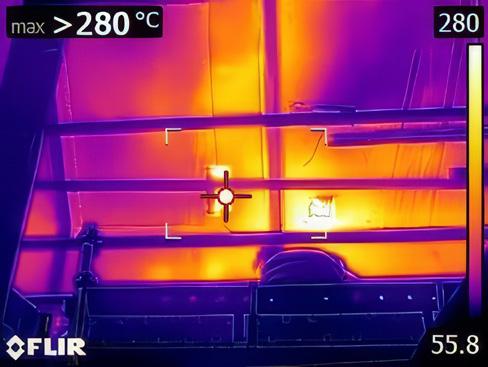
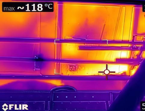
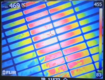
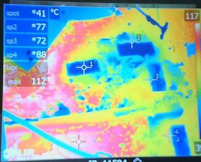
reformer developed a substantial hot spot measuring 3 m x 1.5 m. Over an 18 month period, prolonged exposure to high temperatures had caused significant deterioration to the integrity of the shell, resulting in steel deformation. Despite attempts to control the situation through steam quenching, temperatures continued to rise, posing an increasing threat to the shell’s structural integrity.
With the next planned turnaround scheduled three years away, the plant faced a difficult decision. An emergency shutdown for repairs would have resulted in substantial production losses but leaving the issue unaddressed posed significant risks. The plant needed to address hot spots while maintaining normal operations.
The IGS Hot-tek team safely completed the repair within seven days, maintaining full operational capacity throughout the process. This intervention enabled the unit to continue operating safely until its next scheduled turnaround. By avoiding an emergency shutdown, which would have required at least three days of downtime, the plant saved over US$5 million in production losses. This case study demonstrates how advanced repair solutions can effectively address critical infrastructure issues while preserving operational continuity and avoiding significant financial impact.
Managing hot spots in primary reformers remains a time-sensitive challenge for fertilizer plants. These areas not only pose immediate risks to operational safety and equipment integrity but can also result in substantial financial losses if not addressed promptly and effectively. While traditional approaches to hot spot repair often require downtime, potentially resulting in millions of dollars in lost production, there are solutions available to repair hot spots online.
Advanced technologies such as hot refractory repair enable plants to safely conduct repairs while maintaining normal operations, effectively eliminating the need for costly shutdowns. The case studies presented in this article demonstrate the economic benefits of this approach in order to avoid production interruptions and costly downtimes.
Furthermore, the integration of inspection tools are providing plants with proven ways to approach preventative maintenance. This ability of such tools to safely conduct high-temperature furnace inspections while equipment remains operational allows facilities to identify and address potential issues before they develop into critical problems. This proactive approach to maintenance not only extends equipment lifespan but also helps plants optimise their maintenance scheduling and resource allocation.
The future of primary reformer maintenance lies in these modern technologies and methodologies that prioritise both operational continuity and equipment integrity. Plants that adopt such solutions position themselves to achieve greater operational efficiency, reduced maintenance costs, and improved long-term reliability of their critical equipment.


Igor Makarenko, Solex Thermal Science, Canada, explores the impact of thermal management on production and product quality.
Each stage of the fertilizer production process plays a critical role in making sure that the final product meets industry standards. While granulation, drying, and coating often receive a lot of the attention, cooling is often overlooked, despite its critical impact on product quality, storage stability, and downstream handling.
Before fertilizer is packaged, stored, and shipped, it must be properly cooled. This is more than just a mechanical step, but a process that safeguards fertilizer against product deterioration. If the granules retain too much heat, the residual moisture can lead to clumping – which
not only affects product integrity, but also complicates handling and transport.
Fertilizer operators have many different technologies to choose from to optimise the cooling stage. Rotary coolers, fluidised beds, and plate-based moving bed heat exchangers (MBHE) have all been widely used for decades, with each technology offering their respective advantages to processing different grades of fertilizer.
This article will focus on the role that plate-based MBHEs play at the fertilizer cooling stage, with special attention as to how the technology is able to handle the rapid removal of residual heat, ensure precise moisture management, and prevent granule agglomeration to ensure a consistently high-quality finished product.
For proper storage and transport, fertilizers must be cooled so that their final temperature remains within 10 - 20°C of the ambient environment. This prevents moisture migrating from the air to the product, leading to agglomeration or caking – the consequence of which not only threatens product quality, but also leads to issues such as excessive dust and increased safety risks when the product is being unloaded from storage, due to the high temperatures. Most often, the cause of caking can be traced back to inadequate cooling.
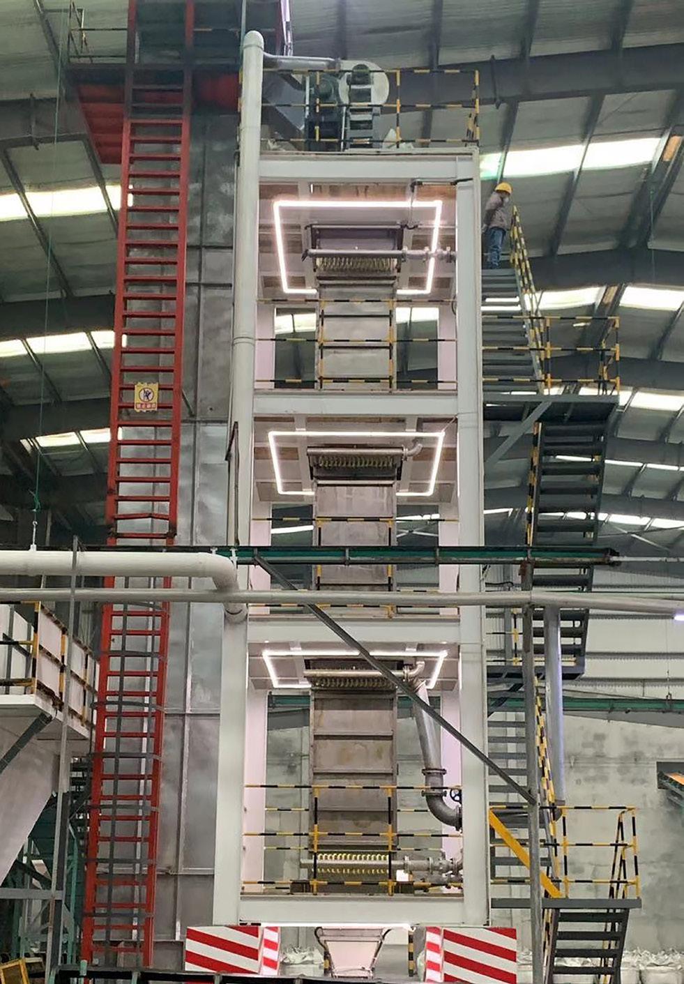
Caking happens when moisture trapped in the granules causes them to stick together. Fertilizers such as NPK, urea, and MAP/DAP products are hygroscopic, as are fertilizer salts such as potash. This means they will start to absorb moisture from the surrounding air at a precise humidity – otherwise known as critical relative humidity (CRH). Moisture transfer from the air to the fertilizer, or condensation, will then, when combined with dust, lead to product caking.
The available moisture originates from the air entrained within the fertilizer, which fills the pore space. For example, if the air enters at 75°C with a relative humidity of 35%, it will contain about 96 g of water per kg of dry air. As it is cooled – for example, to 40°C – the air will only be able to hold 49 g of water per kg of dry air at 100% relative humidity. It also means 47 g of water per kg of dry air will condense out of the air as it is cooled, creating moisture.
Plate-based MBHEs are suited to mitigate subsequent product caking through a process that relies on conduction as opposed to convection (air cooling).
With this technology, the product enters a vertically oriented heat exchanger and then flows by gravity through a series of parallel stainless steel plates that contain cooling water or other fluid mediums. The plates absorb the heat and the product cools indirectly as it slowly and uniformly moves downward. A level probe/transmitter in the inlet hopper maintains the proper product level as it controls the variable frequency drive (VFD) on the feeder.
The cooling fluid in plate-based MBHEs flows counter-current to the product bed. This allows for greater thermal efficiency and, as a result, more effective cooling. In addition, the plate design provides more surface area to cool the product than direct-contact alternatives, such as rotary coolers and fluid beds, and in a more compact space. The typical required footprint for a plate-based MBHE is 2 m x 2 m.
While plate-based MBHEs are effective in reducing product caking in subsequent stages, improper setup or maintenance can lead to caking on the plate surfaces themselves, potentially compromising cooling performance. The key to avoiding this from occurring is to add small amounts of purge air at target dew points – which are below the temperature of the fluid-cooled plates. This can prevent condensation, which leads to caking.
It is important to note, however, that air is not used as the cooling medium in plate-based MBHEs. In fact, less than 2000 m 3 /h or 1200 ft 3 /m of purge air is needed at a particular location in the heat exchanger.
Product quality is not the only challenge fertilizer producers face when the installed cooling solution is inadequate. In hot and/or humid climates, certain cooling methods can also be insufficient in keeping up with production demands, leading to planned production rate turndowns.
For example, the cooling capacities of rotary coolers and fluid beds can be limited when the ambient air is too hot – which, for many parts of the world, can be upward of 48°C during the summer months. The typical temperature required for stable storage of fertilizer should be in the range of 40 - 45°C.
The capacity constraints of direct-contact rotary coolers and drums trace back to their reliance on high volumes of air – not just for the heat transfer, but also for scrubbers or baghouses that must clean the air in accordance with local emissions tolerances. The load on these air-cleaning systems is often too much in these climates, given that the ambient air is too hot and/or humid to cool the fertilizer.
This creates a bottleneck that leads to ‘stack cooling’ the hot fertilizer in warehouses for several days. The process not only complicates plant logistics – for example, demurrage and warehouse management –but also leads to scheduled planned production rate reductions in which producers have to lower their throughputs so the cooling capacity can catch up. In doing so, producers are not fully maximising the sale of their product to local and global markets.
Plate-based MBHEs bypass the stack cooling stage by allowing producers to consistently cool their product prior to packaging and storage, independent of ambient temperatures. Because it relies on conduction as opposed to convection, or forced air, to cool fertilizer, the technology is not influenced by ambient conditions.
By doing so, producers can send cooled product directly to the loadout, thereby eliminating the need for inefficient warehouse cooling practices and avoiding planned production rate turndowns.
In the case of Novomoskovskiy Azot (NAK Azot), a subsidiary of EuroChem Mineral and Chemical Co., the company faced production constraints and product quality concerns due to inadequate cooling capacities at its granulated urea plant.
Specifically, the producer was seeking to debottleneck calcium ammonium nitrate production, which, at the time, relied on three parallel fluid bed coolers designed to lower the post-granulation fertilizer temperature to between 65 - 75°C. The product was then conveyed to a rotary cooler for secondary cooling, and then to bulk storage for three to four days, where the company was forced to wait until the temperature dropped to 35 - 40°C.
During this process, the still-hot product heading into bulk storage was highly susceptible to drawing in moisture from the atmosphere, which also led to caking. This forced the company to reclaim the caked product using two Kratzer-Crane scrapers, which led to variable grain-size distribution and a high percentage of fines.
To achieve better quality control, NAK Azot started by upgrading its rotary cooler to allow for anti-caking additives to be injected into the hot fertilizer before sending it to bulk storage. This helped to reduce the amount and thickness of the caking.
The producer then turned to plate-based MBHEs to increase its cooling capacity. The process involved taking
the product directly from the fluid bed dryer at a temperature from 65 - 70°C, and then discharging it at an optimum temperature of between 37 - 41°C.
The switch to plate-based MBHEs allowed the producer to eliminate its reliance on bulk storage, thereby recouping the three-to-four-day final cooling time. In addition, the producer avoided breakage or degradation of the granules. Overall, the process allowed the granules to keep their form, resist caking, and hold their integrity during storage and transportation.
Satisfied with the results with calcium ammonium nitrate, the company has since expanded its use of
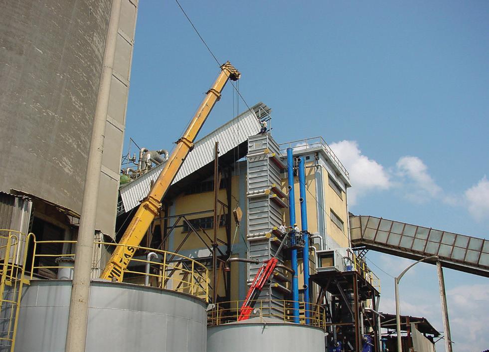
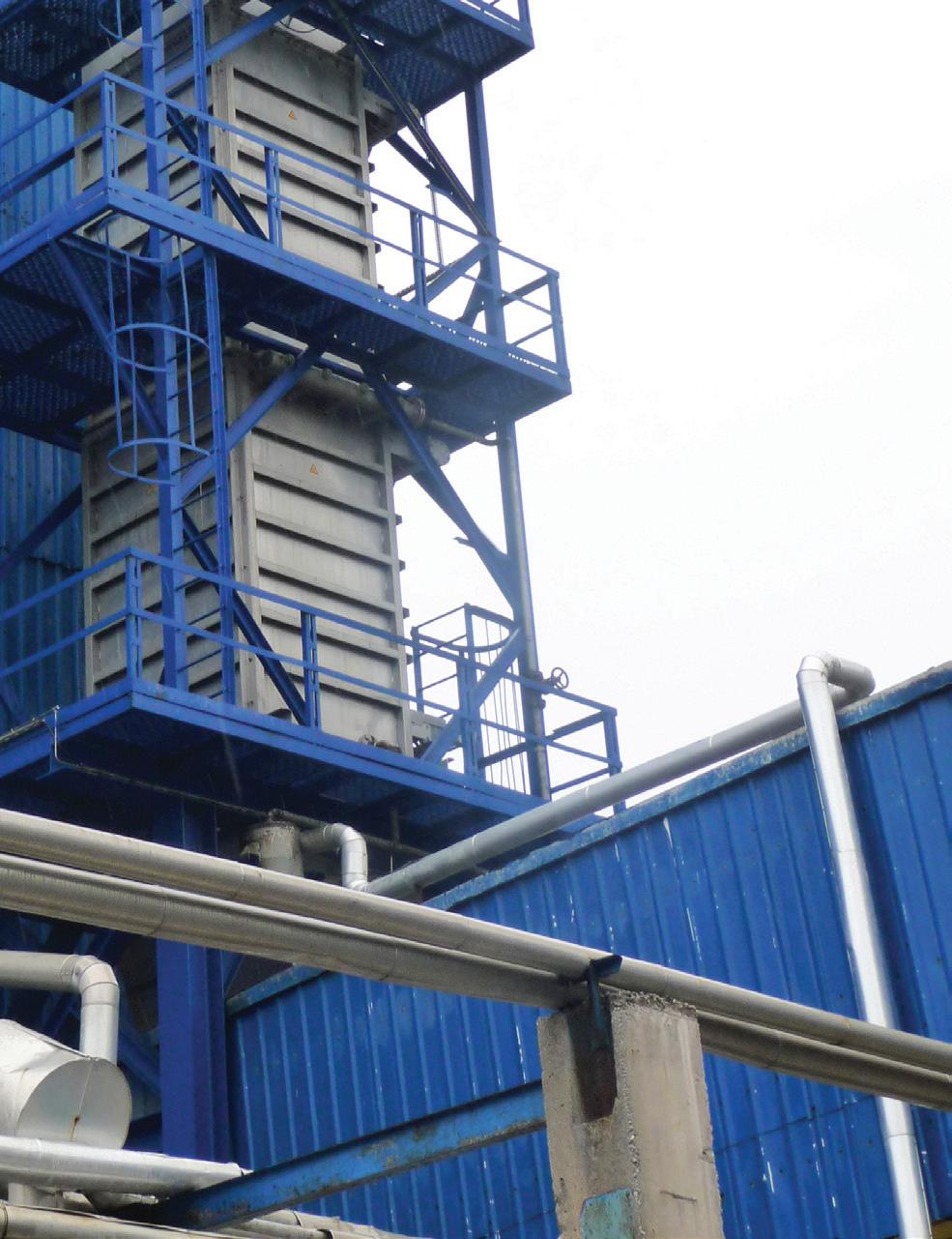
plate-based MBHEs to also cool its high-density ammonium nitrate.
JSC Belaruskali found itself in a similar need of a solution to decrease its potash temperature before distribution.
As a natural insulator, potash can require significant time to cool, especially when the ambient air temperatures in storage areas and transport cars are not low enough to efficiently advance the cooling process. In this instance, the high temperature processed potash fertilizer was stored in bulk and then moved, through a series of conveyors, to a railcar loading dock.
Because the existing cooling solution was not able to handle the current operational requirements – and to avoid the risk of caking and potential impact of product quality – Belaruskali was forced to substantially reduce its production throughput, and accommodate additional cooling days before moving its product from storage to loading and transport.
Rather than continue to accept this inefficiency in its process, the potash producer added a plate-based MBHE at the cooling stage. Initially, the company installed a small-scale unit as an incremental step in its pre-distribution to ensure that the technology could be adapted to its fertilizer production, ambient conditions, and operating requirements. Confident in the unit’s ability, the company moved to a full-scale version approximately a year later.
As a result of a more effective cooling process, Belaruskali was quickly able to resume and accelerate its
regular potash fertilizer throughput schedule. The emphasis on quickly and efficiently cooling its newly produced product allowed the company to achieve a stable product temperature, ensure product quality through both the storage and distribution process, and, ultimately, feel confident in its product quality year-round, regardless of ambient environmental condition.
Fertilizer production can be a complex process that requires continued innovation if the industry is to meet demands for quality control, sustainability, and operational efficiency. While maintaining high standards has always been a priority, shifting regulations, environmental pressures, and rising global food demand is going to place even greater scrutiny on how fertilizer is produced moving forward.
To stay competitive, producers must take a fresh look at the technologies used throughout production –especially during critical stages such as cooling. Having the right cooling solution in place is about more than just preventing caking or improving handling, it is also fundamentally important if producers hope to comply with evolving jurisdictional regulations, as well as support global food security.
In a world where demand for high-quality fertilizers continues to grow, producers that invest in proven, efficient, and adaptable technologies will be best positioned to remain competitive and meet future challenges.


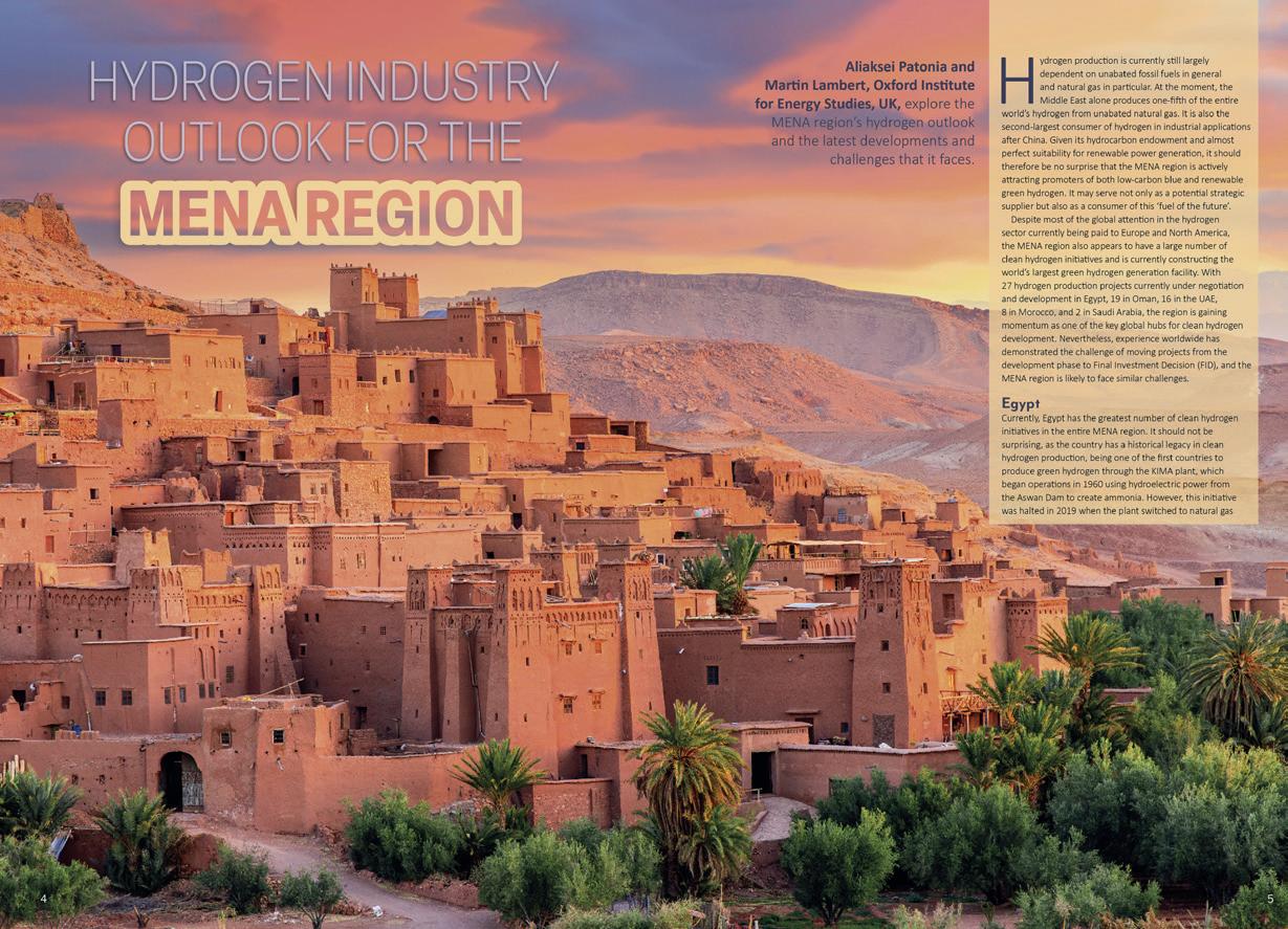


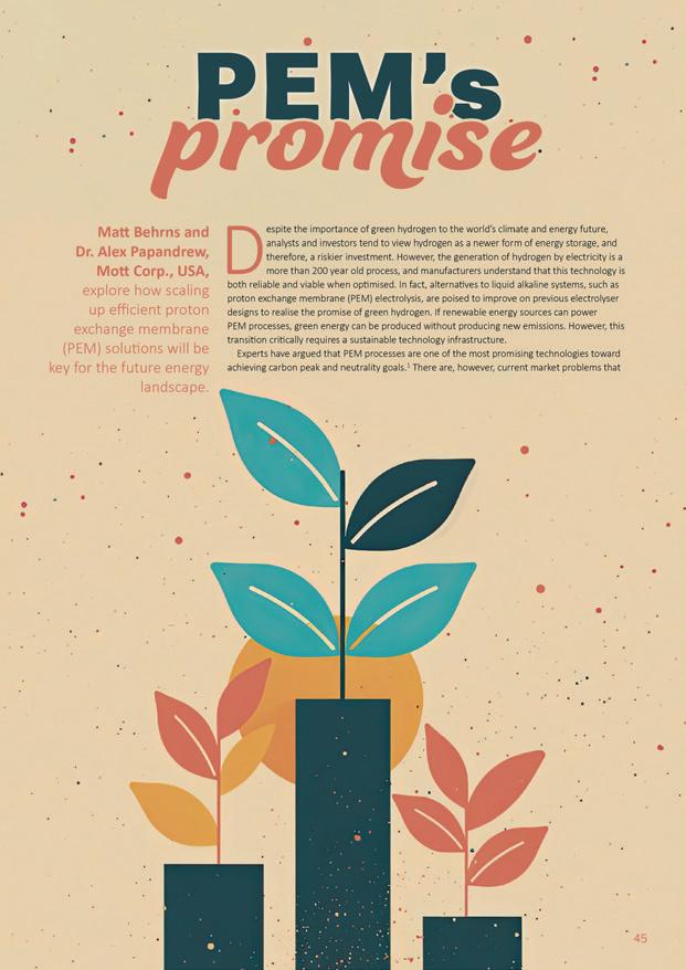

At Casale, we believe in the power of innovation to shape a better world: this is the goal that guides everything we do.
Our commitment to sustainability drives us to integrate cutting-edge technologies with engineering, contracting, and construction solutions that harmonize industrial progress with environmental stewardship.
From green ammonia, low carbon hydrogen, and renewable methanol to sustainable fertilizers, melamine, and other chemical derivatives, we are at the forefront of creating solutions for a brighter tomorrow.
Driven by curiosity, we are also pioneering advances in the storage and transport of clean energy, ensuring a greener, more sustainable future for everyone.
Join us on our journey to make a lasting impact-together, we can build a greener future.