

SMARTER TERMINAL OPERATIONS START HERE
Optimize planning, scheduling, and product demand forecasting with Honeywell's cloud-hosted, Terminal Manager solution.
Purpose-built for marine and rail operations, the software delivers real-time insights through integrated dashboards and key performance indicator tracking, ensuring peak performance.
Seamless interoperability with other industry equipment makes integration effortless-maximizing efficiency, visibility, and ROI.
Reimagine what your terminal can do.


03 Guest comment
04 North American energy assets
Gordon Cope, Contributing Editor, considers how geopolitical turbulence is affecting North American energy assets, and how such pressures may play out.
08 Ensuring safety and efficiency in LNG storage
Dandee Bacani, Endress+Hauser, Japan, provides a comprehensive overview of managing LNG tanks.
13 Bridging the gap between production and operations
Chris Reckers, VEGA Americas Inc., USA, examines how the integration of Industrial Internet of Things (IIoT) and advanced sensor technologies is improving operational efficiency.
17 If it ain’t broke, don’t fix it
Thomas Kemme, AMETEK Level Measurement Solutions, USA, considers how traditional instrumentation technology has remained resilient and versatile in modern markets and applications.
21 An ounce of protection
Travis Sachs, 3DS Technologies, Canada, explains why 3D laser scanning for proactive tank monitoring is a prudent and cost-effective management strategy.


25 Tank maintenance in the digital age
Laurent Bourgouin, Samp, USA, discusses how digital twins and reality capture technologies can improve asset management, safety, efficiency, and decision-making through accurate, real-time 3D visualisations and data integration.
29 Maintenance for critical equipment
Dave Godfrey, Rotork, UK, considers how flow control actuators benefit from regular, proactive maintenance in severe service applications.
33 Pressure relief through redundancy
Kumar Dinesh, Baker Hughes Valves, UAE, examines methods to protect tanks and pipelines from the risks of overpressure.
37 Q&A with CB&I
Tanks & Terminals sits down with Mark Butts, President and CEO of CB&I, to consider the company’s new ownership structure and future growth and expansion plans.
40 Up in the air
Michael Harrison, Sherwin-Williams Protective & Marine, discusses how renewable feedstocks could put your tank lining choices up in the air, and how biofuel processing trends are necessitating careful lining selections for sustainable aviation fuel and beyond.
47 Maximising tank bottom life
Daniel Fleck, Becht, USA, discusses how tank inspections and effective safeguarding strategies can maximise tank bottom life, with particular emphasis on API 653 intervals.
51 Complete corrosion protection
Julie Holmquist, Cortec® Corp., USA, explains why tank and terminal owners must address corrosion inside, under, and around aboveground storage tanks.
The increase in LNG spot trading leads to large fluctuations in the gas composition, challenging the efficiency of terminal operations. As global demand increases, smart systems and accurate instrumentation are becoming increasingly important. On p. 08, Dandee Bacani discusses how accurate measurement is essential to ensure safety and efficiency with unpredictable supply sources.
Automation starts with precision. We deliver the measurement technology.


Everything is possible. With VEGA

Industry 4.0 sets high standards for the future of sustainable production. Our level and pressure instrumentation is designed to meet these demands, combining the essential features that enhance quality, efficiency, and flexibility in your processes –every single day.


GUEST COM MENT
CONTACT INFO
MANAGING EDITOR James Little james.little@palladianpublications.com
SENIOR EDITOR Callum O’Reilly callum.oreilly@palladianpublications.com
ASSISTANT EDITOR Oliver Kleinschmidt oliver.kleinschmidt@palladianpublications.com
EDITORIAL ASSISTANT Emilie Grant emilie.grant@palladianpublications.com
EDITORIAL ASSISTANT Ellie Brosnan ellie.brosnan@palladianpublications.com
SALES DIRECTOR Rod Hardy rod.hardy@palladianpublications.com
SALES MANAGER Chris Atkin chris.atkin@palladianpublications.com
SALES EXECUTIVE Ella Hopwood ella.hopwood@palladianpublications.com
PRODUCTION MANAGER Kyla Waller kyla.waller@palladianpublications.com
HEAD OF EVENTS Louise Cameron louise.cameron@palladianpublications.com
DIGITAL EVENTS COORDINATOR Merili Jurivete merili.jurivete@palladianpublications.com
EVENTS COORDINATOR Chloe Lelliott chloe.lelliott@palladianpublications.com
DIGITAL CONTENT COORDINATOR Kristian Ilasko kristian.ilasko@palladianpublications.com
DIGITAL ADMINISTRATOR Nicole Harman-Smith nicole.harman-smith@palladianpublications.com
JUNIOR VIDEO ASSISTANT Amélie Meury-Cashman amelie.meury-cashman@palladianpublications.com
ADMIN MANAGER Laura White laura.white@palladianpublications.com
CONTRIBUTING EDITORS Nancy Yamaguchi Gordon Cope
SUBSCRIPTION RATES
Annual subscription £110 UK including postage /£125 overseas (postage airmail).
Two year discounted rate £176 UK including postage/£200 overseas (postage airmail).
SUBSCRIPTION CLAIMS
Claims for non receipt of issues must be made within 3 months of publication of the issue or they will not be honoured without charge.
APPLICABLE ONLY TO USA & CANADA
Tanks & Terminals is a supplement of Hydrocarbon Engineering. Hydrocarbon Engineering (ISSN No: 1468-9340, USPS No: 020-998) is published monthly by Palladian Publications Ltd GBR and distributed in the USA by Asendia USA, 701C Ashland Avenue, Folcroft, PA 19032. Periodicals postage paid at Philadelphia, PA & additional mailing offices. POSTMASTER: send address changes to HYDROCARBON ENGINEERING, 701C Ashland Ave, Folcroft PA 19032.

S15 South Street, Farnham, Surrey
GU9 7QU, UK
Tel: +44 (0) 1252 718 999
JAY CRUZ SENIOR DIRECTOR OF GOVERNMENT AFFAIRS AND COMMUNICATIONS, INTERNATIONAL LIQUID TERMINALS ASSOCIATION (ILTA)
ix months into the 119th Congress, the political landscape under the second Trump Administration has taken shape. President Donald Trump has repeatedly expressed his commitment to bolstering the nation’s liquid fuel industry in his tenure.
The International Liquid Terminals Association (ILTA), the only trade association advocating solely for the bulk liquid terminals industry in Washington D.C., has been hard at work moving several key issues for the sector in this new administration. Below is an overview of the two most pressing matters that can and should be addressed by Congress and the White House in the next two years: EPA’s 2024 final gasoline distribution rule and PFAS firefighting foam liability protection for terminals.
EPA gasoline distribution rule
In May 2024, the Environmental Protection Agency (EPA) finalised amendments to its rule titled ‘National Emissions Standards for Hazardous Air Pollutants for Gasoline Distribution Facilities and New Source Performance Standards for Bulk Gasoline Terminals.’ In its finalised amendments, EPA revised the requirements for storage vessels, loading operations, and equipment to reflect cost-effective developments in practices, processes, or controls, as well as to reflect the best system of emission reduction for loading operations and equipment leaks.
ILTA has long been engaged on this issue, meeting with EPA since the proposed rule was published in 2023 to steer it in a productive direction. New EPA Administrator Lee Zeldin has sided with industry, and ILTA continues to work with its experts on revisions.
PFAS firefighting foam liability protection
Per- and polyfluoroalkyl substances, also known as PFAS, are key ingredients in liquid terminal firefighting foams, specifically aqueous film-forming foams (AFFF). ILTA member facilities, long required by Occupational Safety and Health Administration (OSHA) standards, must store and use AFFF to address any potential fire event that could jeopardise the health and safety of workers, the surrounding community, and the environment. Moreover, terminals are designed with extensive fire suppression systems specifically designed for AFFF and often test these systems to ensure emergency preparedness.
The CERCLA designation of PFOA and PFOS places the risk of legal and financial liability on ‘passive receivers’ of PFAS, such as bulk liquid terminals, who were acting in accordance with legally required safety standards. Terminals, as good actors and passive receivers for foams, should not be held liable for PFAS remediation under a potential Superfund designation. ILTA is working with several congressional offices to introduce a bill that would provide such liability protection for entities that have had to rely on AFFF for their safety operations for decades.
Moving forward
Again, this is only a small overview of ILTA’s advocacy efforts. ILTA continues to be engaged with its membership to better understand how it can represent the critical terminals industry in Washington D.C.

Gordon Cope, Contributing Editor, considers how geopolitical turbulence is affecting North American energy assets, and how such pressures may play out.
As if the constantly shifting challenges of regional demand, environmental priorities, and security-of-supply were not enough, President Trump has added to the instability with tariffs. This article looks at how energy assets, including tanks and terminals, are rapidly adjusting to the winds of change that are blowing through North America.
Canada
Production in the oil sands in northern Alberta now stands at 3.2 million bpd of bitumen and synthetic crude,

but is set to expand significantly. Canadian Natural Resources announced that it intends to grow its 1.4 million bpd output by approximately 5% over the next two years, and Cenovus has plans to add another 80 000 bpd by the end of the decade. Enbridge, which supplies the majority of pipeline egress from Fort McMurray, is planning on adding up to 1 million bpd capacity by 2035.
Canada, which exports approximately 4.4 million bpd to the US, has several major crude terminals in Alberta. At the Edmonton terminal, Gibson Energy added three new tanks in 2024, bringing total capacity to 3 million bbl.
The largest terminal in Canada is in Hardisty, Alberta, which sits astride several major crude pipelines. Enbridge is the biggest operator, with 10 million bbl of surface storage and 3 million in underground caverns. The company is planning to spend US$2 billion to expand its pipeline and storage capacity on the Canadian segment of its mainline system over the next two years.
The 890 000 bpd Trans Mountain Expansion (TMX) pipeline, which entered service in 2024, is already shipping 24 loads per month to Asia from its Pacific tidewater terminal in Burnaby, British Columbia (B.C.), Canada. Trans Mountain says it can increase capacity on the line by up to 300 000 bpd by adding drag reducers and new pumps. In addition to the 1.6 million bbl tank expansion in 2024, Trans Mountain would have to add significant new tanks and loading piers to handle the 30% increase in nameplate pipeline capacity.
Likewise, LNG is getting new impetus. After years of lagging behind the US, B.C. has finally woken up to the importance of liquid gas exports. LNG Canada, Shell’s massive, 14 million tpy complex in the Pacific port of Kitimat, B.C., will begin delivering LNG to Asian customers in 2025. It is being followed by nearby Cedar LNG, which will use a floating liquefaction plant to produce 4 million tpy by 2028. The B.C. government is now onboard after feeling the pinch from Trump’s actions; it is promoting the fast-track development of several other projects, including the 12 million tpy Ksi Lisims LNG, the 3 million tpy FortisBC plant, and the 2.1 million tpy Woodfibre LNG project. Feedstock for the plants will come from the massive unconventional gas reserves in northern B.C. and Alberta. Once again, several billion dollars of greenfield tanks and terminals will be necessary to handle the load.
AltaGas operates the Ridley Island Propane Exporting Terminal (RIPET), located in the deep-water port of Prince Rupert, B.C., and approximately 50 000 bpd are loaded onto very large gas carriers (VLGCs), for delivery to Asia. Thanks to growing demand for propane in Asia, AltaGas and Dutch partner Vopak recently announced the Ridley Energy Export Terminal (REEF), a versatile facility capable of handling a variety of commodities, including propane, butane, and (potentially) green ammonia. The expansion would add 50 000 - 60 000 bpd of export capacity and 600 000 bbl of storage, at a cost of approximately CAN$500 million. The site is currently under construction with commissioning expected in late 2026.
Even though the east coast of Canada offers shorter routes to the European market than the US Gulf Coast, the development of crude terminals and LNG on the Atlantic has been glacial. The Québec government in particular has been obstreperous; it objected to the proposed Energy East crude line that would have seen a tidewater export terminal developed in New Brunswick, Canada. Now, in light of the instability generated by Trump, the provincial government has stated publicly that it would be interested in revisiting a previously-rejected proposal to build the massive
11 million tpy GNL Québec plant in the Saguenay region on the St. Lawrence River.
US
The growth in US crude production over the last decade has been propelled by unconventional resources; the Permian Basin now produces 6.4 million bpd, around 40% of total US output. But annual increases are starting to slow; the US Energy Information Administration (EIA) predicts that the basin will reach 6.6 million bpd by the end of 2025. More significantly, PADD III (US Gulf Coast region) exports, which peaked at 4.5 million bpd in February 2024, have since settled to around 4 million bpd.
In response, the impetus to build deep-water export ports in the Gulf to allow supertankers to fill directly is beginning to wane. Currently, the only facility that can fully load a 2 million bbl very large crude carrier (VLCC) is the Louisiana Offshore Oil Port (LOOP). The Enbridge Ingleside Energy Centre (EIEC) and the South Texas Gateway Terminal (STGT), both in Corpus Christi, Texas, US, require lightering to reach full loads.
Enterprise Products Partners’ offshore Sea Port Oil Terminal (SPOT), Phillips 66’s Bluewater Texas project, and Energy Transfer’s Blue Marlin project, which are all in various regulatory stages, are looking less economically viable. In light of slowing growth in the Permian Basin, pipeline operators are shelving plans for future lines to the coast. In addition, a combination of regulatory hurdles, a lack of customers looking to book firm capacity, and a shift of Russian oil away from European customers to Asia has diminished the need for more facilities to fill VLCCs.
LNG plants
The rush to build new LNG plants is also beginning to slow. In 2024, the US Gulf Coast exported an average of 12.1 billion ft 3/d, and the EIA estimates that figure will rise to 13.8 billion ft 3/d in 2025 as the Plaquemines LNG and Corpus Christi LNG Stage 3 projects come on-stream. The pipeline for new projects is beginning to run dry, however. Although President Trump cancelled the Biden administration’s pause on LNG development, other issues are stalling new projects. ExxonMobil’s Golden Pass LNG export plant hit the brakes after a lead construction contractor went bankrupt. Rio Grande’s NextDecade LNG project faces delays due to a court ruling over its FERC authorisation. In addition, rising costs for materials and labour, retaliatory tariffs from China, and the commissioning of plants that are located much closer to Asian markets (such as LNG Canada) are eating into the bottom line and creating market uncertainty.
However, as interest in LNG shifts away from the US Gulf Coast, other regions are coming to the fore. In January 2025, Trump’s cabinet officially backed the development of LNG in Alaska, US. The Alaska Gasline Development Corp. (AGDC) is a state-promoted enterprise that seeks to commoditise up to 34 trillion ft 3 of gas that is stranded on the North Slope adjacent to the Prudhoe Bay field. The US$44 billion project would see an 800 mile mainline capable of delivering up to 3.3 billion ft 3/d to the Pacific port of Nikiski, Alaska, where
a liquefaction plant would produce up to 22 million tpy of LNG for export to Asia. Japan, which is eager to avoid potential tariffs, is urging Tokyo-based Mitsui to invest; the massive conglomerate would bring LNG technology and marketing skills to the project, as well as deep pockets.
Cushing
The crude terminal in Cushing, Oklahoma, US, is at the crossroads of several major pipelines and serves as the premier crude terminal in North America. Eight companies, including Enbridge, Plains All American, Magellan, and Energy Transfer, own the majority of storage assets. The terminal has a nameplate capacity of 98 million bbl, but a working capacity of approximately 76 million bbl, as the farms have to maintain approximately 20 million bbl to ensure functionality.
In January 2025, stocks fell to the 20 million bbl minimum, a level that has not been seen since 2014. The near-record low was due to year-end draw-downs due to tax purposes, as well as the diversion of Canadian crude deliveries to Asia due to the commissioning of the TMX, which added 600 000 bpd of capacity deliverable to tidewater near Vancouver, B.C.. Levels at Cushing subsequently rose after Midwest refineries curtailed deliveries due to scheduled off-season maintenance. By the end of March 2025, crude stocks stood at almost 23 million bbl.
In May 2023, Prairie Energy partners announced that it would build a greenfield 250 000 bpd plant designed to produce low-carbon fuels using blue hydrogen adjacent to the Cushing terminal. The planned start-up date in late 2025 has been pushed back due to complications regarding the acquisition of a suitable site.
Green energy
Over the early part of the decade, Canadian Prime Minister Justin Trudeau and US President Biden established net zero goals for wide swathes of their economies by 2050 and incentivised companies to invest in environmentally-friendly projects that create renewable fuels in North America.
German-based RWE formed an alliance with LOTTE Chemical, of Korea, and Japan’s Mitsubishi to build a clean ammonia production and export facility in the port of Corpus Christi, Texas. The plan is to build a series of units with a final capacity approaching 10 million tpy by 2030.
Air Products is building a revolutionary hydrogen energy complex in the Fort Saskatchewan industrial region near Edmonton, Alberta. The CAN$1.6 billion facility will create 2200 tpy of blue hydrogen, also using ATR. Air Products will then use its 55 km pipeline network to deliver blue hydrogen to Shell’s diesel refinery, as well as to third parties in the industrial region.
ExxonMobil is planning its first world-scale plant for the production of low-carbon hydrogen at its refining and petrochemical facility at Baytown, Texas, US. It expects to produce up to 1 billion ft 3/d of hydrogen made from natural gas; over 98% of the associated CO 2 will be
captured and permanently stored underground (the equivalent of taking 2 million cars off the road). The site would be the largest low-carbon hydrogen project in the world at planned start-up in 2027 - 2028.
Problems
Both Trudeau and Biden are no longer in power. President Trump has threatened the cancellation of green hydrogen subsidies of up to US$3/kg offered by Biden’s Inflation Reduction Act, which would effectively render major low-carbon projects uneconomical.
During the 2024 COP29 climate negotiations in Baku, Azerbaijan, ExxonMobil CEO Darren Woods warned the Trump administration against abandoning initiatives that promote carbon reduction, stating that global emissions will only worsen if not addressed. 1
Tariffs aimed at Canadian energy is another major issue. In February 2025, Trump threatened to tack on a 25% tariff (later lowered to 10%) on the 4.4 million bpd of crude that Canada exports to the US. Tariffs aimed at metal imports will also have an impact on LNG construction costs, as the plants use large amounts of special cryogenic steel and aluminium.
The future
In the near-term, little is expected to alter in energy trade on the continent. The US will continue to import Canadian oil, largely because the Midwestern refineries (which account for about 20% of US capacity) are configured to handle the heavy Canadian bitumen emanating from the oil sands; reconfiguring to process light, sweet crude from the Permian basin would cost billions of dollars. Canadian heavy crude is also likely to continue to flow to US Gulf Coast refineries as traditional sources of Venezuelan and Mexican imports dry up.
In the longer term, Canadian exports will likely be diverted in larger quantities to Asian markets. In addition to up to 1.2 million bpd heading to Asia via TMX, there is renewed interest in building greenfield pipelines. A decade ago, provincial and federal governments were against the construction of the Northern Gateway pipeline, which would have exported 525 000 bpd of bitumen from Alberta through the port of Kitimat, B.C., Canada. Now politicians, following public aversion to Trump’s actions, are keen to build egress.
In conclusion, the near-term future of North America’s oil and gas sector is heavily clouded by the changeable nature of the US administration. Tariffs and aversion to climate change initiatives will cause short-term uncertainty in investment decisions regarding a wide range of capital investments, including tanks and terminals. In the longer-term, reality is expected to return, allowing stakeholders to make decisions based on meeting the needs of both domestic and international demand for both conventional and renewable energy.
Reference
1. COLMAN, Z., ‘Exxon’s chief has a warning for Republicans’, Politico, (12 November, 2024). https://www.politico.com/ news/2024/11/12/exxon-ceo-us-climate-policy-00188927

Dandee Bacani, Endress+Hauser, Japan, provides a comprehensive overview of managing LNG tanks.

With the energy industry making large strides towards a cleaner future, LNG is set to be a key player in this energy transition. With this, the need for new infrastructure and storage systems for LNG to address increased demand will be paramount. As well as this, it will also be necessary to address the safety, efficiency, and environmental impact of LNG’s utilisation. This article highlights the importance of managing LNG storage tanks.
LNG storage
The effective utilisation of LNG necessitates addressing critical factors such as safety, efficiency, and environmental impact. The cryogenic temperature of LNG, maintained at approximately -162°C, presents significant technological challenges in handling and storage. LNG storage tanks are engineered to sustain these cryogenic conditions, thereby preventing the LNG from reverting to its gaseous state. Managing the inherent properties and behaviour of LNG is essential for maintaining its stability and safety.
Proper instrumentation
Proper instrumentation for LNG storage tanks is a key factor in providing operators with the necessary information to make intelligent and timely decisions during plant operation. These tanks are quite large today and up to 100 m dia. and 60 m high, and are capable of storing 270 000 m3 of liquid. The tanks are filled from ships, then the liquid is regasified and fed into distribution pipelines for electric power generation as well as direct use by commercial and residential users. All of this requires appropriate instrumentation to measure liquid level, temperature, density, pressure, and flow. The information must be collected and presented in a user-friendly way to enable operators to manage the LNG plants in a safe and efficient manner.
Unique factors of cryogenic liquid storage
Storing LNG at cryogenic temperatures introduces unique challenges that must be properly managed to ensure safe and efficient plant operation. One major issue is the potential risk of ‘rollover’, which occurs when two layers of LNG with different densities mix rapidly, releasing large amounts of gas. This can lead to several serious consequences:
n Safety hazards: increased pressure and vapour release can cause structural damage.
n Loss of product: released gas can escape into the environment.
n Operational disruption: the event can disrupt normal operations, necessitating emergency measures to manage the pressure and gas release.
Offloading/mixing operation
The conditions in an LNG storage tank that could lead to a rollover event is the formation of a light layer on top of a
heavy layer. There are several ways this can come about but the most common is the offloading of lighter LNG from an LNG tanker into a storage tank that contains heavier LNG. If this happens, there is no natural reason for the layers to mix. The difference in density to inhibit mixing depends on many factors, but in the literature a difference of 1 kg/m3 is considered sufficient. Heat leakage through the insulation of the storage tank causes energy to build up in the lower layer and the density to decrease. At the same time, the lighter elements of the LNG in the upper layer tend to boil off first, making the upper layer heavier. At some point, the layers converge to similar density values resulting in the phenomenon called ‘rollover.’
The layers do not actually roll over, but the name has become common in the industry.
Rollover prevention
To prevent such a condition, operators normally try to make sure that the layer does not form in the first place. When loading a tank, the heavy LNG is normally filled from the top and the light LNG is filled from the bottom. If this is always done, the heavy LNG sinks and leads to complete mixing so that no layer can form. While some older LNG storage tanks may not have the ability to be filled from the top as well as the bottom, all newer tanks have that capability. Of course, this also requires that the exact density of the LNG both in the tank and on the ship is known.
Minimised boil-off gas (BOG)
A second phenomenon that runs counter to this normal procedure is the natural evolution of BOG during filling operations. When top-filling a tank with heavier (and colder) LNG, the liquid tends to ‘flash’ when the colder LNG hits the warmer LNG. When this happens, this BOG must be dealt with in some way. Depending on the design and facilities of the LNG plant, it might be compressed into liquid and returned to the storage tank or possibly fed into the plant’s gas supply line. As a last resort, it can be flared off, but this of course means a loss of product. Regardless of which option is chosen, all solutions cost money, thus the plant operators will try to minimise the production of BOG.

LNG tank instrumentation
To effectively address these and other operational challenges, it is crucial that LNG storage tanks are equipped with appropriate instrumentation.
Standard instrumentation for LNG storage tanks typically includes two level gauges (either servo or radar),
Figure 1. Typical complete LNG system (redundant signal form field, interface and system).

Process improvement
is ensuring plant availability while ensuring compliance.
In the oil and gas industry, ensuring highest safety and plant availability is crucial, while achieving decarbonization goals has also become a critical imperative. Our comprehensive portfolio and expertise enable process improvements that increase operational reliability and move us towards net zero targets.

two in-tank temperature arrays, a high-level alarm gauge, a linear displacement transducer (LTD) gauge for obtaining temperature and density profiles, and an array of temperature sensors outside the storage tank. The internal temperature sensors are initially used to monitor the cool down process, while the external sensors serve as leak detectors. These instruments are integrated into a comprehensive system that provides operators with a complete overview of tank conditions, enabling intelligent and timely decisions to ensure safe and efficient tank operation.
LTD density meter
In some resepcts, the LTD instrument is somewhat unique among these instruments. A single probe is traversed over the entire depth of the LNG in the tank. The probe contains both a temperature sensor and a density sensor. The temperature and density at different levels are sent to LNG management system and the data is displayed in a graph. In this way, any stratification can be easily analysed and detected. The LTD unit is often used to measure the density of the LNG in the tank before loading operations commence and is then used again to scan the tank once the operation is complete. This verifies that the correct loading decision has been made, and if not, stratification is immediately detected so that the most cost-effective decision can be made to eliminate the stratification.


LNG management system
Since it is not always possible to eliminate all layers within an LNG storage tank, it is beneficial to identify potentially hazardous layers. A small layer that results in a manageable amount of BOG can be advantageous if the gas evolution can be safely controlled. Accurate prediction of such scenarios depends on numerous factors and requires specialised software, such as stratification detection and rollover prediction software. This software has proven to be highly effective and can justify its cost if even a single potential hazard in an LNG storage tank is safely managed.
Additionally, temperature monitoring for cooldown and leak detection is available as a standard part of the system, ensuring comprehensive and efficient management of storage tanks.
Future trends in LNG
At the time of writing, the worldwide surge in production and usage of LNG increases. Due to commercial factors, there is a much greater mix of supply sources than before. In the past, receiving terminals tended to receive LNG from a limited number of sources. The composition of the gas was usually known and many plants had an effective plan in place to deal with any differences. In recent years, however, so-called ‘spot trading’ has increased significantly. This term is used to describe the purchase of a shipload of LNG at random; thus, the composition can vary greatly. China is one of the nations that has been using this practice more intensively in recent years. In practice, this means that precautions need to be taken to deal with much wider composition (density) ranges. It is expected that this trend will continue in the future.
Again, the right instrumentation is one of the most important factors in dealing with this change and the strategic advancements in Beijing’s energy transition are clear to see. As Beijing accelerates its low-carbon transition, natural gas has become a cornerstone of the city’s energy strategy, now accounting for 33% of its energy mix. Beijing Gas Group Co. Ltd plays an important role in delivering natural gas across various sectors, including residential, industrial, heating, refrigeration, power, and transportation.
The Tianjin Nangang LNG receiving terminal represents a significant infrastructure investment, featuring eight 220 000 m3 and two 200 000 m3 super-large LNG storage tanks. These tanks are equipped with Endress+Hauser LNG tank gauging instrumentation and management systems, exemplifying proper instrumentation in LNG storage tanks. At full operational capacity, the terminal will handle 5 million tpy of LNG, playing a critical role in securing energy supply for the capital and meeting the natural gas demands of the Beijing-Tianjin-Hebei region.
Conclusion
LNG is poised to be a major factor in the energy transition in the foreseeable future. There is no doubt that new LNG infrastructures and storage tanks will be added to address each country’s energy demand while meeting low-carbon energy solutions. The effective utilisation of LNG necessitates addressing critical factors such as safety, efficiency, and environmental impact. In storage tanks, proper instrumentation and complete LNG management systems are necessary to achieve these critical factors.
Figure 2. Endress+Hauser team during commissioning.
Figure 3. Cooldown and leak detection temperature.
Chris Reckers, VEGA Americas Inc., USA, examines how the integration of Industrial Internet of Things (IIoT) and advanced sensor technologies is improving operational efficiency.
Since the advent of the computer age, the sensors that the industrial world uses to measure and automate processes continue to become more functional and dependable. Companies, such as VEGA, continue to set the pace for the development of sensors used for level, pressure, and density measurement, providing solutions for applications and processes that were not possible a decade ago. But measurement quality is just one piece of the puzzle –of growing importance for end users is not just the sensor itself, but the data that it can provide and the value that data represents – not just on the plant floor, but across the entire organisation. As a result, measurement solution providers are working to provide new ways to transmit and analyse

measurement data, bridging the gap between production and operations and realising new efficiencies that were not previously possible due to distance and firewalls.
The industrial world has traditionally seen sensors and control systems to measure various properties of manufacturing processes and use those values to manipulate and automate processes locally. The result is a more consistent and higher quality product, and a higher degree of safety to the people that work on those processes. However, in most instances this information is quarantined to the production floor because there is no connection between the information systems that drive production and operations. This means that information that might drive better visualisation of an


organisation’s manufacturing processes cannot make it into the hands that can use that data to make informed decisions.
The industrial revolutions
The concept of the fourth industrial revolution (known as Industry 4.0) was introduced in 2011 at the Hannover Messe fair. Specifically, they predicted that the catalyst for the next major industrial revolution would be the removal of the barriers between the production floor and operations by using cyber-physical systems – networks of local standalone hardware systems tied together virtually using the power of Industrial Internet of Things (IIoT) – to create networks not just of sensors, but also shared data that was more accessible than ever before. Since the term ‘Internet of Things’ (IoT) was coined in the 1990s, we have seen several milestones that clearly demonstrate that we are on the precipice of the next industrial revolution. In 2009, Cisco Systems estimated that the number of ‘Things’, or devices requiring no human input, outnumbered human users of the internet for the first time. And in 2021, the market value of IIoT devices surpassed the market value of IoT devices in the consumer space. Most projections show that the future market value of IIoT devices is expected to at least double in the next five years. It is quite clear that momentum is building toward digitisation of the industrial world.
But why is the industrial world moving in this direction, and what needs are being fulfilled by these solutions?
Many organisations are embracing IIoT (connected devices) to assist in various tasks that were previously impractical or impossible to accomplish with human effort alone.
Among these tasks are things like asset tracking (monitoring location and health of vehicles, tools, and other equipment), intelligent maintenance (monitoring physical component health and addressing maintenance needs proactively), and remote control (remotely manipulating production process attributes), to name a few.
Inventory management and production monitoring are also critical applications where IIoT can be used to bridge the gap to the future. Running out of raw materials or storage capacity means an interruption to production. These problems become magnified when processes and decision-makers are physically separated from one another by greater distances. The ability to monitor raw inventory and storage capacity and assess the health of critical operations in real-time can result in a sizeable positive impact to organisations and dismiss the status quo in favour of greater operational efficiency, increased uptime, and maximised revenue.
Industry applications
Take the case of an upstream oil and gas exploration company operating a remote wellhead site in the Mountain West, for example. This remote site is unmanned most of the time, with the closest office located several hundreds of miles away. While a scheduled maintenance visit is conducted each day by a technician, local control measurement and visualisation functions were limited and any manipulation of valves to divert the flow of extracted crude was done manually. The employees in the remote office became wary of the potential for overfill events and unexpected interruptions to production. In addition, there was no remote visualisation to determine inventory levels or
Figure 1. Crude oil tanks at a remote wellhead site.
Figure 2. VEGAFLEX 81 guided wave radar sensors measuring continuous level and inventory in crude oil tanks.
Figure 3. A VCCS13 enclosure including a VEGASCAN 693 for transmission of sensor data to the VEGA Inventory System hosting service.
production status. This resulted in a general lack of confidence at the office in what was occurring at the remote site, and the fear of potential lost production and revenue at best, and a dangerous and potentially costly overfill event at worst.

They ultimately decided that while the long-term goal was to implement sensors and invest in an on-site control system to automate these processes, the immediate need was to provide continuous visibility of inventory and critical processes to the office, with critical real-time notifications to notify the office of the need for immediate action to prevent overfill events and drive timely collection of processed inventory. The solution needed to provide visibility to the remote site in the short-term, while allowing expandability to a local control system in the future.
Each of the eight aboveground tanks containing collected crude oil were equipped with a guided microwave level sensor. This sensor uses ultra-low frequency (1 - 2 GHz) microwave energy guided by a cable probe to the surface of the crude oil and back to determine the distance of the product from the sensor. When the tank dimensions are populated in the sensor, the sensor can indicate the fullness of the tank and can be represented both with a process value (such as percentage or
filling) and an inventory value (such as gal. or bbl). Guided wave radars have no moving parts and are not affected by temperature, pressure, or other atmospheric elements such as vapour, and do not require ongoing periodic calibration to maintain its +/-2 mm accuracy specification.
Pressure measurement was also required at two heater treaters, a free water knock out (FWKO) drum, and a heated knock out (HKO) drum to aid in separation of extracted crude oil. Additionally, operators wanted to monitor pressure from local field gas and utility gas sources. For each application, a ceramic dry-cell pressure transmitter was chosen to monitor process pressure. Ceramic measuring cells are highly resistant to wear, can manage extreme pressure overload conditions without damage, and do not require periodic calibration.
This customer needed a hybrid solution to allow sensor data to be transmitted remotely for visualisation, with the possibility for future integration into a local control system.


Figure 4. A graphic view of the crude oil tanks on the VEGA Inventory System portal.
The guided wave radars and pressure sensors with ceramic measuring cells are equipped with HART communication, which allows multiple sensors to be wired into the same circuit and report sensor values digitally to a controller for processing. These sensors were connected to a controller, which collects values from the sensors and makes those values available both via Modbus registers over TCP-IP to a local control system, but also uses an event function to encode the measurement data and send it to an external data server.
In this case, the data is being sent to the VEGA-hosted VEGA Inventory System (VIS) server via an encoded message which can flow either through a facility’s LAN and internet, or separately via a cellular router. This data is sent using two integrated reporting modes: standard and measured value difference. The standard reporting interval to the server can be as frequent as every 15 minutes – at this interval, the current values of all connected sensors are transmitted.
Another function called ‘measured value difference’ is activated in addition to the standard reporting interval. This function continuously monitors the measurement values of each sensor and reports at a faster interval – as frequently as every two minutes – when the change exceeds a certain value between normal reporting intervals. That means that when there
are rapid changes in the sensor data, those changes can be visible remotely within a two-minute window of occurrence.
Looking forward
With more comprehensive data and process visibility, operators appreciate how they can set up user-defined alerts. These notify users that an inventory or process limit has been exceeded in real-time. Even if a user is not actively monitoring measurement data on the server, they will receive an e-mail or a push notification to notify them of an event. For their tank battery, the operators defined a critical high-high level alert which notifies them via e-mail and push notification when the tank inventory exceeds 370 bbl. The alert results in a timely notification that diversion of material into another tank is required. They can also set a first-stage high level alert that can notify them when to conduct collection on-site to ensure that pickup is done in a timely manner and when needed, optimising logistics and minimising fuel costs. Both are pointed alerts that notify personnel that intervention is required sooner rather than later.
Not only is measurement point data in the portal available in real-time and on-demand, but two years of historical trend data is also available for analysis. Plant professionals can use this information to assess the health of the production process and determine if longer-term adjustments need to be made. All data hosted on the server is available externally via API, so it can be integrated into other platforms.


In the case of remote areas where power supply and connectivity are problematic, ‘autarkic’ non-contact continuous level radar sensors fix the aforementioned issues. They are powered by an internal battery, feature 80 GHz radar for a high degree of accuracy and adaptation to a variety of applications and media, and can transmit values wirelessly via IoT-specific protocols such as NB-IoT, LTE-M, and LoRaWAN for maximum connectivity even in areas where connectivity is not thought to be possible. This is the perfect solution to gain visualisation of bulk materials deployed in the field and outside of the production facility, including fracking chemicals, sand, mud, fuels, and water.
Figure 5. Historical trend data for one of the crude tanks showing inventory position over time and critical high-high level alert.
Figure 6. Trend comparison showing historical pressure measurement data from two heater treaters.
Thomas Kemme, AMETEK Level Measurement Solutions, USA, considers how traditional instrumentation technology has remained resilient and versatile in modern markets and applications.
There is a convenience to modern technology that cannot be ignored, yet a debate to be made that products were once simpler and lasted longer. As enticing as digital transformation may be, the additional hardware and software can add complexity to products, opening the door to new modes of frustration. This can be the case with newer instrumentation technologies coming to the

market, as operators take in their respective benefits alongside potential trade-offs.
Yet, the fundamental mechanical design of displacer level switches remain unchanged. Many oil terminals and tank farms storing hydrocarbon liquids still feature various tall, blue, metal housings which serve as high-level switches on all kinds of storage tanks. Many in the industry refer to these products as a ‘Magnetrol’
due to being the namesake of a level instrumentation brand with its roots in magnetic level control.
Versatility
Whether it is a single or multi-point level requirement, a light or heavy specific gravity, displacer level switches continue to find a home in these applications.
The different types of tanks and storage liquids that are in use highlight the versatility of displacers, ranging from terminals storing natural gas liquids (NGLs), diesel, crude, or any other hydrocarbon liquid. Some of these tank varieties will be discussed in the following section,

Figure 1. Displacer level control on floating roof tanks: the Model A15 triggers a high-level alarm to prevent overfilling and spills. The Proof-er option allows functional checks without raising the liquid level and resets automatically.

Figure 2. Control and safety devices on additive tanks. This setup includes control and safety devices such as the Pulsar® model R86 radar transmitter and the model A15 displacer switch, which ensures accurate level detection and prevents overfilling.
when the importance of detecting either a liquid or a floating roof is emphasised. For installation, the switches are wired, and the displacers are adjusted along a cable and suspended into the process or storage vessel at the desired switch actuating levels. There is no additional configuration or field calibration required.
The majority of displacers are used as a single point level switch; however, there are various displacer arrangements for applications requiring multiple set points. For instance, displacers are still a popular technology for controlling pump operating sequences (fill and drain cycles) in sumps and in other more remote applications. What is particularly useful is that these level switches only make or break a circuit, and do not require additional power to operate the instrument. This feature can be beneficial to any remote site or terminal where power supply is limited.
API 2350
The standard API 2350 applies to above ground atmospheric storage tanks with capabilities greater than 1320 gal. (5000 l) that store Class I or Class II flammable or combustible liquids. It contains the most widely accepted guidelines for overfill prevention in the industry. Even a site that does not exactly meet the requirements of API 2350, or where the standard does not directly apply, can benefit from these best practices to mitigate a potential loss of primary containment. Benefits of following API 2350 include:
n Increasing personnel safety and the safety of the surrounding area.
n Reducing the risk of an environmental impact resulting from a spill, along with associated clean-up fees and environmental fines.
n Lowering liability insurance costs through risk reduction and maintaining safety measures.
n Protecting public brand reputation.
One of the critical parts of API 2350 are the tank categories and recommended level instrumentation, including both automatic tank gauges (ATG) and high-level alarms. Different tank categories range from Category 0 being fully attended, to Category 3 being unattended, with requirements differing by the category. For example, a high-high level alarm must be included in Category 2 and 3 tanks, while being optional for other categories, with Category 3 tanks requiring an independent high-high alarm from the ATG. The high-high alarm can be either continuous or point level and must have different entry points into the tank from the ATG.
The high-high level alarm is where displacer level switches have performed for decades. What sets them apart from other technologies is their feature-set on floating roof tanks. On floating roofs, dual level detection is required of either the roof or the liquid (should the roof become submerged). One of the classic Magnetrol-branded level switches for a high-high alarm is furnished with a non-sparking, hollow brass displacer capable of detecting both levels. It is often supplied with
Powerful Solutions for Tank Emissions Calculations
Market-leading cloud-based and desktop-based applications.
BREEZE TankESP
Intuitive desktop-based program that uses emission estimation procedures from AP-42 Chapter 7 to calculate emissions from floating- and fixed-roof tanks.
BREEZE ESP+
Robust, cloud-based solution utilized by companies worldwide that includes all TankESP capabilities plus additional benefits including the ability to calculate emissions from:
f Catch Pans
f Combustion Units
f Control Devices
f Equipment Leaks

f Line/Vessel Openings
f Loading Operations
f Sumps/Oil-Water Separators
f Vacuum Trucks
Simplify and streamline your emission calculations today.
Purchase access to BREEZE ESP+ or TankESP and experience what a difference our solutions can make!

a manual check, called a ‘proofer’ cable attached to the instrument, which simulates a high-level condition to verify operation without the need to move tank level.
Reliability
Ultimately, the key to displacer level switches continuing to prove their resilience over the years is that they simply work. The streamlined mechanical design allows for a quick installation with minimal maintenance over time.

This design includes a spring that is loaded with a weighted displacer suspended from a cable, which is either immersed into liquid resulting in a buoyancy force change or lifted by the floating roof (if the displacer is selected for floating roof detection). As liquid covers the displacer, or the roof rises and lifts the displacer, the spring compresses and a magnetic attraction sleeve attached to the spring moves upward inside of a non-magnetic enclosing tube. This attraction sleeve draws-in a magnet attached to a switch mechanism, which actuates the switch located on the outside of the enclosing tube. An inherent advantage is that the enclosing tube acts as a barrier from the process if switch mechanisms must be replaced over time.
The result of this design is that instruments are installed in the field for decades, occasionally over 50 years, before the need to fully replace. It also provides increased familiarity and reduced training for onsite personnel due to simplicity of installation, maintenance, and testing.
Conclusion
The versatility and reliability of displacer level switches were instrumental in why they were first specified in safety-critical applications and that continues to hold true in storage tanks and process vessels all over the world. Their utilisation has only increased with the adoption of API 2350, providing a tried-and-true high-high level alarm for overfill prevention.


Figure 3. Aerial view of oil storage tanks.

Travis Sachs, 3DS Technologies, Canada, explains why
3D laser scanning for proactive tank monitoring is a prudent and cost-effective management strategy.
In the oil and gas industry, tanks are indispensable assets, vital for storing and managing critical materials. However, the risks associated with tank management are significant.
Corrosion, structural failures, and leaks can lead to catastrophic environmental impacts and financial losses. In this environment, waiting for a crisis to occur is no longer an option. 3D laser scanning offers a proactive approach to tank monitoring and management, ensuring safety and efficiency while minimising risks.

Figure 1. Regular monitoring through 3D laser scanning not only prevents unexpected breakdowns but also extends the lifespan of tanks. 3DS Technologies uses the high-speed Leica RTC360 laser scanner, shown here, as well as other Leica laser scanning technology to ensure high quality results (image courtesy of Leica Geosystems).

Figure 2. 3D laser scanning captures comprehensive data that supports asset management efforts and can be integrated into existing systems to enhance overall operational efficiency (image courtesy of 3DS Technologies).

3.
Tank monitoring with 3D laser scanning
The process of tank monitoring with 3D laser scanning involves several key steps. Initially, a detailed scan of the tank is conducted, capturing precise measurements and identifying any anomalies. Scans are captured without disrupting operations and can be completed in just a few hours with the right technology. This data is then analysed and compiled into a comprehensive report, providing actionable insights for maintenance and management. The deliverables typically include a detailed assessment of the tank’s condition, along with recommendations for any necessary repairs or maintenance.
The entire process can be handled in-house. Alternatively, it can be outsourced to a service provider. Reputable, experienced service providers should be able to provide a complete project turnaround as fast as 24 h from scan to deliverables.
Key benefits of 3D laser scanning
Accuracy and precision
3D laser scanning technology offers unmatched accuracy and precision, capturing data with millimeter-level detail. This capability is crucial for detecting even the slightest deviations or damage in tank structures. The precision of laser scanning allows issues to be identified before they escalate into major problems. This level of detail is essential for preventing catastrophic failures that could have severe environmental and financial consequences.
Moreover, the precision of 3D laser scanning is vital in industries where compliance with strict safety and environmental regulations is mandatory. By utilising this technology, companies can ensure that their infrastructure meets the required standards, thereby avoiding costly penalties and enhancing their reputation for safety and reliability. The ability to produce highly detailed and accurate reports also facilitates better decision-making, allowing engineers and maintenance teams to prioritise repairs and upgrades effectively.
Time and cost efficiency
In addition to its accuracy, 3D laser scanning is both time- and cost-efficient. The process is quick, with scanning completed in a matter of minutes to hours and reporting often available by the next day. Whether the service is insourced or outsourced, the expense is a fraction of the cost compared to dealing with the aftermath of an incident. By investing in regular scans, companies can significantly reduce the likelihood of expensive repairs and downtime.
The cost-effectiveness of 3D laser scanning is further enhanced by its ability to provide comprehensive data in a single pass, eliminating the need for multiple inspections. This efficiency translates to lower labour costs and reduced time spent onsite, allowing companies to allocate resources more effectively. Additionally, the ability to quickly assess and respond to potential issues means that operations can continue with minimal interruption, safeguarding revenue streams.
Figure
Regular 3D laser scans of tanks can be compared over time to identify early signs of deformation or stress.

Regular monitoring and maintenance
Establishing a baseline through initial scanning and conducting regular scans thereafter is key to effective tank monitoring. This proactive approach allows for the early detection of structural changes, enabling timely maintenance and repairs. By addressing potential issues before they become critical, companies can avoid the significant costs associated with emergency repairs and environmental fines.
Regular monitoring through 3D laser scanning not only prevents unexpected breakdowns but also extends the lifespan of tanks. By keeping track of wear and tear over time, companies can plan maintenance activities during scheduled downtimes, minimising disruptions to operations. This foresight in maintenance scheduling leads to more efficient use of resources and ensures that the facilities remain operational and safe, bolstering overall productivity.
Comprehensive data collection
Beyond the tanks themselves, 3D laser scanning captures extensive data that can be beneficial for other areas of the plant. This comprehensive data collection supports broader asset management efforts and can be integrated into existing systems to enhance overall operational efficiency.
The data collected through 3D laser scanning can be used to create detailed digital models of the entire facility, facilitating better planning and optimisation of plant layouts. These models can help identify potential bottlenecks and inefficiencies, enabling companies to streamline operations and improve workflow. Furthermore, the ability to visualise the plant in 3D aids in training and safety drills, ensuring that staff are well-prepared to handle emergencies effectively.
Case study 1: gas tank rupture
A critical gas tank, only six months old, ruptured and had to be taken out of service for repairs. This incident involved the insurance company and other stakeholders, delaying resolution for about a year. 3DS Technologies was called in to scan the tank and quickly identified the source of the rupture. The laser scans provided valuable data to help the company recover some of its losses from the tank rupture.
Prevention tip: conduct quarterly or semi-annual 3D laser scanning of all tanks to identify early signs of deformation or stress. This would allow for timely interventions and avoid prolonged operational disruptions and financial implications of tanks being out of service.
Case study 2: gasoline storage tank deformation
A large gasoline storage tank was deformed after being hit by equipment. The deformation was not immediately obvious, as it was only visible from certain angles. 3DS Technologies scanned the tank and documented a significant half-metre indentation, which compromised the tank’s structural integrity. The tank was then taken
out of service for repairs and recertification. The potential for a major disaster was averted, but the tank had to be repaired and recertified, incurring costs and downtime.
Prevention tip: conduct regular 3D scanning of tanks and scan after any known impact events to quickly identify deformations. This proactive measure can prevent unnoticed damage from escalating into more severe issues.
Integration with digital twins
The integration of 3D laser scanning data into digital twin frameworks represents a transformative advancement in tank monitoring and management. Digital twins serve as dynamic, virtual replicas of physical assets, enabling real-time monitoring, simulation, and analysis of complex systems. By incorporating precise laser scanning data, companies can create highly accurate digital twins that reflect the current state of their assets with exceptional detail. This integration allows for enhanced asset management by providing a continuous, real-time view of the tank’s condition, facilitating predictive maintenance and reducing the likelihood of unexpected failures. As a result, companies can optimise their maintenance schedules, improve operational efficiency, and extend the lifecycle of their assets. This proactive approach not only minimises downtime and repair costs but also enhances safety by identifying potential issues before they escalate.
Furthermore, the integration of 3D laser scanning with digital twins offers significant improvements in decision-making capabilities. By having a comprehensive and up-to-date digital representation of their assets, companies can conduct detailed analyses and simulations to predict future performance and assess the impact of various scenarios. This capability is particularly valuable in planning and executing complex operations, such as expansions or modifications to existing infrastructure. Additionally, digital twins can be used to train personnel and conduct safety drills in a virtual environment, reducing risks and improving preparedness. Overall, the synergy between 3D laser scanning and digital twin technology provides a holistic view of asset health and performance, enabling companies to make informed decisions that enhance reliability, safety, and profitability.
A proactive tank management strategy
Regular tank monitoring is essential to ensure safety, efficiency, and environmental protection.
3D laser scanning offers a proactive and cost-effective solution, providing the accuracy, precision, and comprehensive data necessary for effective asset management. As the technology continues to evolve, its integration with digital twins and other advanced systems promises to further enhance its capabilities, making it an indispensable tool in the future of tank monitoring and management. By adopting these technologies now, companies can avoid the high costs and risks associated with waiting for a crisis to occur.

Laurent Bourgouin, Samp, USA, discusses how digital twins and reality capture technologies can improve asset management, safety, efficiency, and decision-making through accurate, real-time 3D visualisations and data integration.
From overseeing a complex web of infrastructure to effectively accruing data on assets to inform decision-making, the tank storage sector encompasses a broad range of challenges. To balance mitigating risks with driving profitability and keeping a lead on competitors, operators require an accurate and up-to-date visualisation and knowledge of their industrial assets. Without it, they are essentially taking a stab in the dark with their strategy, and plugging holes after incidents have happened.
To step up to this challenge, pioneering technological solutions are reshaping the way the industry approaches managing operations and assets. One example is the use of digital twins and reality capture. These digital tools streamline the complexities in project and asset management to build a data-driven process that allows tank and terminal operators, as well as any stakeholders they engage with, to enhance safety, efficiency, and collaboration on sites. Above all, this means they can drive operational excellence.
How advanced digital twins are filling an industry gap
In short, a digital twin is a virtual 3D replica of an industrial site – but its true potential is often misunderstood. It is not just a buzzword, it is a strategic framework that drives operational excellence. Some of the latest digital twins on the market combine various tools. For example, a solution like Shared Reality integrates artificial intelligence (AI) and 3D technology to build interactive and collaborative digital workspaces that act as a single source of truth of the site. This advanced solution can deploy such a workspace within a few days. After a rapid site survey conducted by a 3D scanning specialist, they capture physical assets and infrastructure on site and build a smart ‘3D reality model’.
Where the latest cloud solutions really stand out against traditional digital twin technology is in their ability to use AI to connect the 3D reality model’s assets to their corresponding technical information or flowsheets. This data could take the form of a process flow
Capturing reality: the bedrock of digital twins
Reality capture is what creates the clear and detailed representation of industrial sites. It involves digitally documenting environments to form accurate, high-resolution 3D representations. Reality capture relies primarily on two advanced techniques: 3D laser scanning, and photogrammetry. Each method offers distinct advantages, delivering results within minutes to a few days.
3D laser scanning: efficiently precise
n Terrestrial laser scanners (TLS): for over two decades, TLS technology has been the heart of reality capture, delivering millimetric accuracy by collecting millions of data points. This method is ideal for producing detailed 3D models in complex industrial environments.
n Simultaneous localisation and mapping (SLAM): more recent advancements, particularly post-COVID-19, have introduced SLAM-based scanners as a faster,

diagram (PFD), a piping and instrumentation diagram (P&ID) flowsheet, and equipment metadata from existing asset management systems, for example. With this information often being out of date or inaccurate, this connectivity can transform how operators manage their tank facilities – which is a current industry gap.
This digital workspace gives teams and stakeholders an in-depth and unified overview of their tank facilities; it offers them swift insights on actual site conditions, and establishes a reliable and accurate picture of data across operations. As the digital twins are interactive, users can visualise, navigate and analyse their sites in great detail. For example, they can identify and amend thousands of inconsistencies in their P&ID, for instance.
The key part is that the technical data can seamlessly be linked with the reality on site. It is a shared reality to work from. This fosters a much greater understanding of a site’s infrastructure and can inform decision making for a variety of projects, from standard maintenance to major projects such as expansions or revamps.
cost-effective alternative to TLS. These portable devices capture subcentimetric spatial data in real time, even in confined or highly dense areas where TLS may not be feasible. SLAM scanners reduce costs and deployment time while maintaining high accuracy, making them particularly useful for hard-to-reach environments and rapid facility surveys.
Photogrammetry: versatile and scalable
Photogrammetry generates 3D models by processing high-resolution images, making it a highly flexible method for both large-scale and localised scans.
n Drone-based photogrammetry: equipped with high-definition cameras, drones efficiently survey large outdoor or elevated areas, such as storage tank tops or inaccessible pipeline sections. The resulting multi-centimetric accuracy is well-suited for site planning and asset monitoring.
n Tablet or smartphone photogrammetry: on a smaller scale, work tablets and smartphones enable localised scans of specific equipment or facility sections. With centimetric precision, this method is ideal for capturing small, targeted areas – perfect for documenting equipment modifications or pipe routing changes by on-site personnel.
The best of both worlds
While 3D laser scanning and photogrammetry each excel in different areas, using them together produces a more detailed and authentic site replica within days. Photogrammetry ensures quick area coverage, while laser scanning delivers highly-detailed representations of intricate equipment. Combined, they form the foundation of modern reality capture, enabling the formation of precise and easy-to-update
3D Reality Models for industrial applications.
Figure 1. NavVis VLX3 Scanner.
Another significant development in this area over traditional methods (which use manually designed 3D CAD models) is the ability for operators to update the 3D reality model independently. In an industry first, when a change is made to infrastructure, any worker in the field can easily update the shared model by using a photogrammetry application on their work tablets or smartphones, while redlining the associated flowsheets. As an example, this could make a significant difference to a tank operator managing 2000 km of pipeline assets across six tank farms.
The benefits of a broader digital asset management system
Digital twins form just one component of a wider digitalisation and asset management system. For an industry where precision and collaboration are fundamental to operations, there are many core benefits from having a digital replica of an industrial site:
Avoiding on-site challenges
As advanced digital twins offer a precise and detailed representation of physical assets enhanced by their current status and properties, operators can proactively prevent unforeseen issues during a project or maintenance.
Streamlining revamp projects
The fact all workers, whether they are internal staff or external contractors, can access unambiguous physical and technical information simplifies engineering and hazard studies.
Enhancing procurement
When there is a call for tenders, the use of 3D streaming web technology means procurement teams can easily interact with external companies, creating quicker proposal times, improved offers and fewer changes and claims.
Speeding up maintenance work
A more visual interface allows operators to spot and tackle maintenance requirements faster, meaning less downtime and better operational continuity.
Constructing collaboration
Having access to a shared reality of an industrial site means that all stakeholders – whether they are site personnel, engineers, or contractors – can access the latest, most precise data and collaborate effectively regardless of their discipline.
Minimising risk and enhancing auditability
Digital tools mitigate risk by rooting operations in real-world environments, making auditing far more efficient and thereby building safer working conditions for everyone.
Where organisations oversee particularly sensitive or complex infrastructure, digital asset management can be an especially useful tool – any difference between real-world conditions and digital data can trigger expensive overruns or safety risks.

GEA Jet Mixer Systems for tank mixing & blending.
The proper amount and arrangement of Jet Mixers produces a three-dimensional flow that mixes the entire contents without creating a rotating motion in the tank. Delivering high efficiency, operational safety, resistance to fouling and little wear & tear thanks to its simple and robust construction. Download our catalog


Immediate connectivity without disruption
Digital twins are adaptable. They can work on their own for a fast start and to deliver immediate value, or integrate seamlessly with a range of data sources, like spreadsheets/flowsheets, and IT systems such as ERP, EAM, and SCADA. Tank storage organisations typically have a multitude of assets spanning many locations, not to mention needing to operate on tight schedules and budgets. This connectivity means their current workflows can operate without disruption as they retrieve, evaluate, and update key information.
As all teams can visualise assets and insights quicker, they can perform tasks faster and, consequently, reduce their project timelines. Costs are also reduced because planning takes place more efficiently and unnecessary expenses can be mitigated. Crucially, as operators can see how technical data connects to on-site realities, they can avoid coming across as many unexpected challenges or nasty surprises once projects are underway.
Credible track record across sectors
Hundreds of industrial sites in many industries are already benefiting from creating a digital shared reality of their assets and operations. In a global market and landscape that is hard to predict, operational resilience is dependent on this digital evolution.
Major players such as Trapil, Elengy, and Storengy in the oil and gas sector use the shared reality ethos to drive their operational efficiency and effectively manage their assets. Storengy alone oversees tens of thousands of assets through a collaborative digital workspace. Meanwhile, the utilities sector has seen key players Engie, Suez, and Veolia integrating digital twins into their workflows, enhancing their competitiveness and operational stability.
The use of digital twins across this spectrum of industrial activity demonstrates their versatility and capability in tackling complex industry challenges and their credible track record.
A smarter future for tank maintenance
As the tank storage industry continues to evolve, digital twins are reshaping how midstream operators manage assets, optimise workflows, and enhance decision making. By enabling seamless data integration, improving cross-team collaboration and generating real-time insights, these technologies empower organisations to overcome operational challenges and build long-term resilience in an increasingly complex landscape.
For terminal operators and midstream players seeking to streamline operations, reduce costs and enhance safety across both field and office teams, embracing digital asset management presents a proven, future-ready solution for driving efficiency and operational excellence.
Figure 5. Work preparation within Shared Reality.
Figure 4. Generational change impact on working methods.
Figure 2. Reality capture P&ID (equipment).
Figure 3. Reality capture P&ID (piping).
Dave Godfrey, Rotork, UK, considers how flow control actuators benefit from regular, proactive maintenance in severe service applications.
When the UK’s Buncefield oil storage terminal exploded in 2005, it was said to be one of the most devastating industrial disasters in recent memory. This tragedy is a reminder of the need for a strict maintenance regime in severe service applications, as it was caused by faulty equipment meant to monitor the level of fuel in a storage tank.1
There is no single definition of a severe service application, it generally refers to processes where the repercussions of equipment failure can be catastrophic. This could include operations involving hazardous chemicals like ammonia or caustic acid. For operators, the key question becomes what are the potential consequences if a specific actuator were to fail?
Effective monitoring and maintenance of all flow control equipment is essential. However, prioritising the highest level of care for the most critical actuators makes the difference. This proactive approach prevents not only costly shutdowns and extensive damage, but also protects lives.
Ensuring optimal performance of critical actuators
Critical actuators that manage flows in the oil and gas industry require ongoing monitoring and maintenance to ensure reliability. A service programme proactively maintains critical equipment to avoid failures. To understand the level of support a site needs, Rotork’s engineers work with companies to consider each individual situation.
The goal is to identify the actuators within a facility that are most critical. These are the ones whose failure would result in the highest costs, the greatest challenges, or the most significant process interruptions. In a facility with 100 actuators, this might mean focusing on just 10 that require the highest level of maintenance due to the severe impact their unavailability would cause.
Not every actuator would cause a serious incident if it were to fail. Rotork offers reliability services, a tiered maintenance contract package. The three tiers – health check, standard maintenance, and enhanced maintenance – provide different levels of cover, but for severe service applications, the enhanced maintenance tier is likely the best fit. Companies can choose an enhanced package for actuators controlling their severe service processes and one of the other levels for less hazardous situations.
Under the health check tier, engineers conduct site visits to inspect actuators. However, the enhanced package offers a more comprehensive approach, with more frequent visits that include detailed inspections of internal components. Engineers remove covers to examine the actuators’ internal workings and replace seals, oil, and parts as needed. This can be further enhanced with an intelligent asset management system, like Rotork’s iAM, where data is gathered on critical metrics such as vibration, temperature, torque, number of starts, and instances of power loss.
This data is fed into an algorithm that enables the team to assess an actuator’s health and make recommendations around maintenance, helping to head off failures, potential safety incidents, and process shutdowns. As industries move increasingly towards electrification, intelligent
asset management is very much linked to Rotork’s IQ3 Pro range of electric actuators, which are fitted with data loggers.
Of course, safety is the most important consideration. One customer operating in Asia has a single actuator on a critical valve that would cost US$1 million per day in downtime if it were to fail. So, whether it is safety or cost, an enhanced maintenance level of service support will likely be appropriate in some situations.
Sustaining performance: managing equipment lifecycles
The rise of electric actuation delivers greater precision, efficiencies, and environmental performance. A proactive approach to lifecycle management ensures actuators are consistently monitored and maintained as they age. This strategy also helps customers plan well in advance for replacement costs, offering both reliability, and financial predictability.
At industrial sites, actuators are categorised into four stages: preferred, supported, mature, or obsolete. For sites equipped solely with preferred products, spare parts are readily available, and engineers have the knowledge and experience to repair and service them. However, managing older actuators is equally important, and this is where lifecycle management and obsolescence strategies come into play, ensuring continued reliability and performance.
If some products are obsolete, spares may no longer be readily available and with older actuators, this is potentially an issue. Companies are likely to face delays while parts are sourced and some parts might no longer exist. Without available spares, they may need to be replaced entirely if a fault occurs.
If a site has 100 actuators that are all obsolete, they might still perform efficiently and could remain operational for another decade. However, if any become unavailable, what could have been a simple, cost-effective repair may instead require a full replacement – resulting in significantly higher expenses. If 10 fail at the same time, the company could face a large, unexpected cost.
Although obsolete actuators are typically excluded from service contracts, engineers remain committed to supporting customers across all assets, regardless of their age.

A recent obsolescence survey at one of the main fuel tanks at the UK’s Gatwick Airport identified several obsolete actuators. As a result, the airport opted to replace 24 units and integrate the new actuators into its maintenance contract.
Specific technology has been developed to control critical actuators effectively and efficiently.
PakscanTM network protocol can control several motorised valves, including those in severe service applications, and can support the full automation of complex plants. This capability delivers savings in both time and costs.
It continuously monitors the actuators to ensure nothing
Figure 1. Asset management systems gather performance data for analysis.


unexpected is happening and enables an operator to override automatic settings to operate any individual actuator. For instance, an operator could precisely open a specific valve to 35% to alleviate pressure build-up.
Pakscan has been installed in one of the most significant offshore development projects in the Norwegian continental shelf, Johan Sverdrup. It controls hundreds of actuators, ensuring optimal performance. Rotork Service is also providing ongoing asset management and condition-based maintenance.
Pakscan can connect up to 240 electric actuators on a single 20 km, two-wire loop. It enables the remote control of actuators and valves and includes built-in field network


redundancy, ensuring uninterrupted control even in the event of equipment malfunctions or cable failures.
In-house aftermarket expertise: intelligent asset management for enhanced site control
Asset management technology offers multiple benefits, such as improving safety, reducing environmental damage, and scheduling, all of which can improve uptime. By addressing equipment issues promptly, potential problems can be resolved before they escalate into critical failures or cause unplanned shutdowns. Such shutdowns can be exceptionally costly and may also pose heightened risks to both safety and the environment.
An intelligent asset management programme analyses data log data to determine actuator conditions, predict upcoming issues, and recommend actions. These diagnostics include key insights like vibration analytics, usage statistics, torque profiles, and health scores.
Improving site uptime
One specific example of this can be found where a service programme helped improve a site’s uptime and optimised its processes at a major petroleum terminal in Malaysia. The project involved the construction and maintenance of storage and distribution facilities needed to transport crude oil, petroleum, chemical, and petrochemical products to the Refinery and Petrochemicals Integrated Development (RAPID) tank farm. The end user ordered more than 570 intelligent IQ3 multi-turn actuators, which were ideal due to their operational accuracy, the ability to download the data logs, and power supply options. IQ3 actuators are also ATEX-certified and suitable for Safety Integrity Level 2/3 applications. Rotork service carried out extensive on-site commissioning. They provided field support for repairs, upgrades, and maintenance through a global network of fully trained and experienced service engineers. This onsite support helped to reduce downtime and improve operational efficiency.
Conclusion
Combining predictive and preventative maintenance provides operators with fixed costs, simplifying budget management. They also provide plans focusing on long-term maintenance and support, moving beyond simply dispatching engineers to address failures. This strategy helps manage the long-term sustainability of the entire facility, enhances uptime, and minimises unexpected repair costs.
Intelligent electric actuators can enhance safety, efficiency, and environmental performance. While ongoing maintenance is essential to all such devices, this becomes much more critical when controlling flows in severe service applications. Buncefield showed how poorly maintained equipment can have severe repercussions. Operators have hopefully learnt from the lesson it provided and act to ensure nothing similar happens again.
Reference
1. ‘Buncefield: Why did it happen?’, Control of Major Accident Hazards, (2011). https://webarchive.nationalarchives.gov.uk/ ukgwa/20220701173308mp_/https:/www.hse.gov.uk/comah/ buncefield/buncefield-report.pdf.
Figure 2. A reliable maintenance plan can help reduce downtime.
Figure 3. A Rotork service engineer carrying out a health check.
Kumar Dinesh, Baker Hughes Valves, UAE, examines methods to protect tanks and pipelines from the risks of overpressure.
In applications requiring the operation of tanks, overpressure protection is crucial for safety, preventing catastrophic failures and ensuring operational efficiency. At worst, a tank rupture can lead to explosions, fires or fatal injury to personnel and at best uncontrolled release of process media can be an environmental risk. Redundant pressure relief devices can prevent the
system from exceeding the maximum allowable operating pressure (MAOP). This article will discuss the potential causes and risks of overpressure, and some common methods for protecting the safety and integrity of tanks and pipelines.
Some of the critical relief scenarios related to overpressure in tanks and pipelines are surge, thermal expansion, and vacuum relief.


Surge scenario
When discussing surge scenarios, the primary concern is with the rapid changes in fluid pressure, often referred to as ‘hydraulic transients’ or ‘water hammer’. These surges can pose significant risks to the integrity of tanks and pipelines. Rapidly shutting a valve can abruptly stop fluid flow generating a pressure wave that propagates through the system. Or changes in pump operation can cause rapid fluctuations in fluid velocity and pressure. Basically, any event that causes a sudden change in the speed of fluid movement can induce a surge.
When one of these events occurs, surge waves can create pressure spikes that exceed the design limits of pipelines and tanks, leading to ruptures or leaks. Surge events also generate significant vibration and noise, resulting in equipment damage or environmental concerns.
To mitigate these risks, a surge reliever in a storage tank farm is a crucial safety device designed to protect tanks and pipelines from damage caused by pressure surges. Transient pressure surges, also called ‘water hammer’, can occur when there is a sudden change in the velocity or flow rate of liquid, such as when a valve is closed quickly, or a pump is started or stopped. The greater the change in flow velocity, the higher the pressure will rise. These pressure surges can travel through a pipeline at sonic velocities, and if left unabated, can cause serious damage and costly inspection of the line.
Surge relief valves are designed specifically to protect against damage from high-speed transient pressure surges. As fluid is being pumped in and out of storage tanks, both the pumps and the valves have the potential to be subjected to a surge event, and the surge relief valve will mitigate that risk. Terminals, often near bodies of water, critically require surge relief protection to prevent pipeline breaks. Figure 1 illustrates the multiple points in a typical storage tank farm and terminal where surge relief may be required.
Surge relief valves are typically installed as close to the surge potential as possible, on a bypass line leading away from the main pipeline (Figure 2). When the main pipeline pressure exceeds the jacket pressure in the surge relief valve, the inner tube is forced away from the core of the device, allowing for fluid media to pass through the barrier to a downstream line and be captured in a collecting tank.


Figure 1. Typical storage tank farm and terminal has multiple areas where surge relief protection is critical.
Figure 2. Example of set up for surge relief valves on a bypass line leading from the main pipeline.
Figure 3. Illustration of how a surge relief valve works.
The fluid can be pumped or trucked back into the main line at lower pressure once the surge subsides. Any transient pressure surges should be analysed for root cause.
How the surge relief valve works
Under normal operation, the pipeline pressure (blue) is less than the jacket pressure plus cracking pressure. The jacket pressure (green) forces the tube against the core of the device and the valve is closed (Figure 3, left).
When the valve set point is reached, the pipeline pressure exceeds the jacket pressure, the tube is forced away from the core, permitting fluid to flow around the barrier into a a downstream line (Figure 3, centre).
When the surge event passes and the main pipeline pressure returns to normal, the jacket pressure reseats the tube against the core, closing the valve (Figure 3, right).
Thermal expansion scenario
Thermal expansion is often caused by changes in ambient temperature, which can cause liquids within tanks to expand and increase pressure. Most substances expand when heated and contract when cooled. This is due to the increased kinetic energy of the molecules, causing them to move further apart or closer together. Liquids in particular can experience substantial volume changes with temperature variations. In a closed tank or section of pipe, temperature variations due to ambient conditions, but also solar radiation or process heating, can all contribute to

Tanks

thermal expansion when the liquid is heated, leading to a significant rise in pressure.
Thermal relief valves offer overpressure protection when a closed tank or section of pipe is exposed to temperature changes. These changes create a slower but substantial increase in internal pressure. Typically, very little liquid needs to be redirected to relieve the pressure, and a direct spring thermal relief valve can be installed for this purpose.
Under normal conditions, the valve spring pressure is higher than the system pressure, keeping the valve in a closed position. When the system pressure reaches the set point, the pressure of the fluid will lift the internal disc off the seat, allowing the fluid to pass through the valve to relieve the pressure. Thermal relief valves (Figure 4) are typically rated to fully open to 10% over set point pressure. As the system pressure decreases comparably to the spring pressure, the disc sets against the seat, closing the valve.
Vacuum relief scenario
There are several causes for vacuum situations in tanks and terminals. Vacuums can occur when liquid is pumped out of a tank, when the liquid or vapour within the system is cooled to a point of contraction, or there are changes in atmospheric pressure. If the internal pressure drops significantly below the external atmospheric pressure, the tank can collapse. Even minor vacuum conditions can cause stress and damage to a tank’s structure over time.


Weight-loaded pressure vacuum vent valves are safety devices used on storage tanks and vessels to protect them from over pressure or vacuum conditions. They are designed to automatically release pressure or allow air to enter the tank when the pressure or vacuum exceeds a predetermined limit. These valves are essential for preventing structural damages to tanks caused by excessive pressure or vacuum.
Pressure vacuum vent valves use a weighted pallet that is held in place by gravity. When the pressure or vacuum inside the tank reaches the set point of the valve, the pallet lifts, allowing pressure to escape or air to enter (Figure 5 and Figure 6). The weight on the pallet determines the pressure or vacuum setting at which the valve will open. These weighted pallet valves are also known as conservation vents or breather vents. This is because one of the primary uses of these devices is to protect low pressure storage tanks that have fixed roofs. Since the design pressures are very low, the simple pumping in of product or increased ambient temperatures can raise vapour pressures in the tank and cause weight loaded valves to ‘breathe’ and discharge the pressure. The sizing and selection of these weight loaded valves is often done per API 2000.
They are very effective at relieving low vacuum situations and are not suitable for high pressure or vacuum applications such as when an external heat source is applied to the vessel contents. For these situations, an additional pressure relief device maybe required to alleviate higher pressure than allowed for by the weighted pallet valve. These devices are simply tank hatches, also called ‘manways’, that normally have hinged covers. The covers have a calibrated weight, moment arm and possibly a counterweight to provide the required set pressure. These emergency relief devices are set at higher pressures than the weighted pallet valves. If called upon to open and relieve pressure, they are designed to stay open until manually closed.
Closed tanks and pipeline systems present multiple risks, requiring redundant over pressure protection devices and systems to prevent exceeding the maximum allowable operating pressure. By specifying and installing the right pressure relief devices, operators can effectively mitigate these risks and ensure safe and efficient operations.
Conclusion
In summary, this article has underscored the potential causes and risks associated with overpressure in tanks and pipelines, while also emphasising the importance of specific critical relief scenarios such as surge, thermal expansion, and vacuum relief. Effective protection hinges on a deep understanding of these factors and the diligent implementation of appropriate mitigation strategies. This includes not only general safety protocols and pressure relief devices but also tailored solutions designed to address the unique challenges posed by these critical relief scenarios, ultimately ensuring the safety and longevity of these essential systems.
Figure 4. Consolidated 19000 Series Thermal Relief Valve. Image courtesy of Baker Hughes.
Figure 5. Relieving excess pressure.
Figure 6. Relieving excess vacuum.


Q&A
WITH...
Mark Butts, President and CEO, CB&I
Mark has over 30 years of experience working in various engineering, technology development, strategic planning, and senior management roles of increasing responsibility for CB&I. As President and CEO, he is responsible for overseeing the financial, commercial, and operational performance of the company. In 2024, he spearheaded the company’s transition to a standalone entity, now owned by a consortium of investors, led by Mason Capital Management, overseeing strategic initiatives, operational improvements, and financial growth, while positioning the company for continued success in the storage sector. Prior to his appointment as President and CEO, Mark served as Vice President of Engineering, leading global engineering and technical strategy for CB&I. Prior to this role, he was head of research and development, where he led the innovation of new storage solution technologies.
01 Since CB&I was divested from McDermott in 4Q24, can you share more about how the new ownership structure under Mason Capital and its consortium of investors is supporting CB&I’s long-term growth strategies?
CB&I recently announced our acquisition by a consortium of financial investors led by Mason Capital Management LLC (Mason), including IES Holdings Inc., Nut Tree Capital Management LP, 683 Capital Management LLC, First Pacific Advisors, and other investors. The closing of this transaction positions CB&I, formerly a subsidiary of McDermott International Ltd, as a strong, independent company with no funded debt.
Mason’s mission is to empower CB&I to achieve its strategic goals, capitalise on new market opportunities, and leverage significant growth potential in the dynamic energy storage solutions sector. CB&I has built a legacy of innovation while setting industry standards in safety, reliability, and performance. CB&I and Mason look forward to working together in driving the company’s vision forward.
Mason and the investors have chosen a capital structure that supports our short- and long-term growth objectives, allowing CB&I to capitalise on the opportunities in front of us and continue delivering successful projects for our customers.
02 Can you describe CB&I’s core product lines and the geographies you serve, and explain where your current focus lies?
CB&I’s core product lines focus on providing world-class storage solutions, including tanks and terminals, for a variety of applications, such as LNG, petrochemical, industrial, and water storage. Our expertise spans from
engineering and design to fabrication, construction, and commissioning. We are recognised for our ability to deliver complex storage solutions, especially in critical areas like energy infrastructure, where safety and quality are most important.
Geographically, CB&I serves customers across the globe, with a strong presence in North America, Latin America, the Middle East, and Asia. Our extensive operations and network of suppliers allow us to execute projects effectively in both well-established regions and more challenging, remote locations.
Our current focus is on leveraging our broad geographic footprint and core engineering and construction capabilities to meet the most demanding energy infrastructure challenges. Whether it’s delivering small-scale storage solutions for remote sites or large-scale storage for major LNG projects, CB&I is committed to providing effective, safe, and high-quality storage solutions. We use our global supply chain network, along with our expertise in logistics and project delivery, to ensure we can deploy construction teams even in the most remote locations. By using our proven and consistent project delivery model, we manage risks and ensure that projects are completed on time, while maintaining the highest safety and quality standards. This allows us to be a trusted partner for our customers, no matter where they operate in the world.
03 Can you talk to us about your future growth and expansion plans within the storage, tank, and terminal sectors?
We are thrilled to partner with Mason and the consortium as we embark on an exciting new chapter as a standalone company. Together with our new owners, we will build upon CB&I’s rich 135+ year
heritage, continuing to collaborate with our valued customers and suppliers to deliver innovative solutions that address the evolving infrastructure needs of the energy and industrial markets. With the closing of this transaction, we are on solid financial footing, which positions us to capitalise on strong end-market demand and to advance our strategic goals.
04 Can you explain CB&I’s project delivery model?
CB&I has built a strong reputation as a project delivery-focused company, and our proven project delivery model is at the core of our business model. Developed over many decades, this model is globally consistent, regardless of product line or geographic location. It starts with our early engagement with customers to develop designs and construction execution plans that are both cost-effective and customised to the specific needs of each project. Our approach integrates risk management at every step of project delivery, from the early design phase through to construction and handover. By proactively identifying and addressing potential risks early on, we ensure that we manage the critical path effectively and keep projects on schedule. This approach allows us to deliver safe, high-quality projects on time, which ultimately helps our customers mitigate risks and achieve goals for their business. By leveraging this reliable project delivery model, we provide our customers with the confidence that their projects will be executed efficiently, safely, and with minimal disruption – supporting strong financial performance and reducing the overall risk throughout the project lifecycle.
05 How does early engagement with customers help ensure that project requirements are clearly defined and aligned from the start, leading to better outcomes throughout the project lifecycle?
By engaging early, CB&I gets a good understanding of the project’s technical, logistical, construction, and commercial requirements. This allows us to provide value engineering options that not only help mitigate risks but also offer solutions that leverage our technical innovations in design and construction techniques.

Early engagement allows CB&I to deliver a technical design that fully considers constructability, ensuring we provide a comprehensive, end-to-end project delivery plan that is both efficient and cost-effective. It allows us to integrate all necessary functions, from sales and engineering to supply chain, fabrication, construction, and commissioning, ensuring that the entire project is aligned and set up for success. This approach enables the smooth delivery of storage solutions, helping our customers achieve their goals while minimising challenges.
06 What are the advantages of integrating FEED with EPC project delivery, and what are the benefits of a phased contracting approach?
Integrating FEED with EPC project delivery and using a phased contracting approach offers advantages in terms of minimising project risk and improving designs, construction cost, and schedule performance. Phased contracting allows preliminary design work that incorporates whole-project solutions from the beginning. By engaging with the EPC contractor for both pre-FEED and FEED engineering as well as construction, this approach ensures that design and constructability are fully integrated from the start, leading to the best end-to-end solutions.
A phased contract, starting with pre-FEED, then advancing to FEED and early EPC activities, and finally transitioning into full EPC, allows all parties to align early on and maintain alignment throughout the project. This integration between FEED activities and EPC engineering, supply chain, and execution planning sets a strong foundation for the full EPC phase. Early technical and construction planning enables the ordering of long-lead materials and equipment ahead of schedule, helping mitigate supply chain and execution risks by managing critical path activities from the beginning.
This approach allows for schedule compression, eliminating the need for a lengthy bidding process between the FEED and EPC phase. Phased contracting results in improved design of storage solutions, a compressed schedule, and reduced levels of risk, benefiting the customer by streamlining the entire project.

Figure 1. ASME pressure vessel of the year – liquid hydrogen spheres for Plug Power in the US.
Figure 2. LNG tanks for Calcasieu Pass LNG in Cameron Parish, Louisiana, US.


Michael Harrison, Sherwin-Williams Protective & Marine, discusses how renewable feedstocks could put your tank lining choices up in the air, and how biofuel processing trends are necessitating careful lining selections for sustainable aviation fuel (SAF) and beyond.
As the energy industry makes notable shifts to increase its production of sustainable fuels, refiners are facing new questions about the compatibility of their storage tanks to house the different raw materials being used and the refined products being produced.
Tanks used to store biofeedstocks and processed biofuels are critical to keep in top condition to ensure the continuous flow of refining operations and fuel distribution. But with lipid-based feedstock materials fluctuating based on market availability, how can producers know if the protective lining materials inside their storage tanks can handle the various commodities – both before and after refining?
Those producers will need to choose carefully when selecting linings for their various tanks. That means first ensuring the coating materials used inside raw material tanks can handle the aggressive nature of acidic biofeedstocks without corroding. Second, producers need to ensure the linings used in tanks storing refined biofuels are compatible with the contents and therefore will not contaminate them.
These two priorities are especially pertinent in the aviation industry where sustainable aviation fuel (SAF) is taking off in popularity. Various testing has been completed on multiple lining materials to ensure their compatibility with both lipid-based feedstocks and the SAF produced from refining those organic materials. This article will review those studies in relation to the SAF market, understanding that the same principles of corrosion mitigation and lining compatibility apply when processing other biofuels. The findings will help refiners make better lining selections as biofuel processing needs climb.
Feedstock changes necessitate lining reviews
Biofuels have a low carbon footprint, releasing far fewer carbon dioxide (CO2) emissions when burned than traditional fossil fuels. Therefore, it is no surprise that the push for emission reductions across the energy industry has led to the increased production of sustainable fuels. In fact, the biofuels market is growing approximately 6% per year, according to the International Energy Agency (IEA).1
While biofuel growth promises positive sustainability outcomes, the processing industry must face the practicalities of accommodating the shifting fuel feedstocks, so it can ensure the refining process itself remains as sustainable as possible throughout the entire production chain.
This attention to operations is necessary, as the raw materials used to produce biofuels have different properties than the crude oils that are traditionally used as feedstocks for fuel production. While fossil fuel feedstocks are corrosive due to


Figure 1. Isothermal tests run for 15 months in accordance with NACE TM-0174 revealed a clear relationship between the duration and temperature of biofeedstock exposure on tank linings, with degradation manifesting at the vapour-liquid interface. The test panels shown feature three different linings subjected to 15 months of exposure in vegetable oil (+DI water) at various temperatures. Checked periodically during testing, the linings had not degraded after six or 12 months of exposure.
the presence of inorganic sulfurous and sulfuric acids, lipid-based feedstocks are more aggressive and corrosive due to their fatty acid content. That corrosivity increases at higher storage temperatures, as well as the longer feedstock materials are stored. Processors must therefore ensure the linings used inside their storage tanks are compatible with lipid-based feedstocks and will hold up to the more aggressive exposures. This assurance will help processors avoid the increased labour, material, and environmental costs associated with repairing early lining failures.
Tank owners also have concerns about biobased material compatibility on the opposite end of the biofuel refining process. While mitigating corrosion in storage tanks housing unprocessed biofeedstocks is the priority on the front end, corrosion is barely a concern on the back end.
Instead, processors are focused on maintaining the purity of refined fuels and need to ensure the contents will not pick up any contamination from the tank lining itself.
Following guidance laid out in API RP 652: Linings of Aboveground Petroleum Storage Tank Bottoms, Fifth Edition, Version 2020, Section 6.7.1 – Selecting Internal Linings for Tanks Storing Alternate Fuels will help specifiers address various considerations associated with protecting tanks housing biofuels (look for a new version of this standard scheduled for publication in 2025). However, due to the new feedstocks and refined materials found in the biofuels industry, decades of track records and laboratory testing for linings are no longer relevant. That history exists for linings exposed to various crude oils at different temperatures but is limited for exposures to biofeedstock materials.
Owners must understand this new normal to answer the question of whether they need to re-line their storage tanks.
Correlation between time and temperature exposure
The only way to confirm whether a lining material will work with an untested biofeedstock is to actually test it.
That includes testing in both the lab and the field to gain a full understanding of the material’s theoretical performance and its real-life performance in an operating tank.
In recent lining material compatibility testing, Sherwin-Williams Protective & Marine examined three of its linings in the lab to determine their resistance to corrosion when exposed to vegetable oil, beef tallow, and vegetable oil with free fatty acids (FFAs) added to mimic waste cooking oil, which is more corrosive. The linings included:
n Nova-Plate® UHS, a solvent-free, ultra-high-solids novolac amine epoxy that is traditionally rated to handle exposure to crude oil at approximately 266°F (130°C).
n MagnaluxTM 2100FF, a novolac glass flake-reinforced vinyl ester, which is an acid-resistant lining rated to approximately 212°F (100°C) for crude oil exposure.
n Nova-Plate® 360, a next-generation, high-performance, inert, flake-reinforced novolac tank lining.
An isothermal test run on the above coatings for 15 months in accordance with NACE TM-0174, Laboratory Test Methods for the Evaluation of Protective Coatings and Lining Materials on Metallic Substrates in Immersion Service, Procedure B, revealed varying rates of coating degradation
Exposure:
A SUPPLEMENT TO HYDROCARBON ENGINEERING

Exploring decarbonisation technology and solutions for the downstream sector
This special supplement focuses on decarbonisation pathways for the downstream sector, highlighting innovative technology and solutions that will help you thrive within the energy transition.

Scan the QR code to download your free copy of EnviroTech 2024.
depending on the temperature of the test (Figure 1), which ranged from 140°F (60°C) to 180°F (82°C). Not surprisingly, panels in the higher temperature tests experienced greater breakdown, confirming that higher feedstock storage temperatures will lead to faster lining degradation and thus greater tank corrosion.

Figure 2. Exposed to high temperatures over time, biobased oils experience a rise in fatty acid concentrations, with the levels often exceeding what the lining material is able to resist.


Exposure: six months of continuous exposure
The length of exposure also mattered. The linings tested had not degraded after six or 12 months of exposure at all temperature ranges. By 15 months, at the higher exposure temperature, some of the lining systems showed varying degrees of degradation. Where degradation of the lining was observed, it commenced at the vapour-liquid interface, suggesting this area is particularly corrosive to the linings.
All three materials performed differently based on their chemistry. Where degradation was observed, there was a clear relationship between the exposure time and temperature. This makes sense based on the nature of lipid-based feedstocks. The oils tend to change composition and become more acidic the longer they are exposed to elevated temperatures. Over time, their increasing FFA concentrations often exceed what the lining material is able to resist (Figure 2).
Cyclical testing points to better field performance
Of course, biobased feedstocks rarely face long-term exposures in field operations. Storage tank cargo typically cycles in less than 30 days, meaning the linings will not ever be continuously exposed to a static feedstock for as long as the 15-month testing periods. Due to this nuance, it was important for the examination of lining material compatibility to also include cyclic testing, so those results could be compared to continuous long-term exposures.


Figure 3. For cyclical testing (top), panels were exposed to vegetable oil and water at 180°F (82°C) for 30 days before the oil and water mixture was replaced for another 30-day cycle. A control group of panels subjected to continuous exposure with no oil cycling (bottom) showed significantly increased corrosion damage compared to the other panels even after shorter exposure periods.
The completion of one 6-month cycle test helped to confirm that shorter exposure durations resulted in improved lining performance. Sample steel panels featuring the same three lining materials – plus one grit-blasted panel left uncoated – were immersed in vegetable oil and water for 30 days at an elevated temperature of 180°F (82°C) in different biofeedstock oils. Every 30 days, technicians removed and replaced 75% of the oils with new material, repeating the process for a total of 16 cycles (so far). They also tested a control group of panels featuring the same linings in a continuous noncyclic exposure test at the same temperature for comparison (with six monthly inspections performed). The panels that underwent cyclical exposures performed significantly better than those subjected to continuous exposure (Figure 3).
Corrosion was notably worse in the highly acidic vapour space above the oil level with all non-coated panels showing signs of pitting corrosion in this area. The oil becomes rancid in contact with air, creating an aggressive corrosive environment that can lead to holes developing in tank roofs. A similar phenomenon occurred at the lower edges of the panels, which were
Exposure: eight months of cyclic exposure
OUR LATEST COATINGS BREAK CONVENTION. YOURS.

It’s common to reuse coatings specs from previous projects – especially coatings that performed well. But our newest coatings may offer even greater durability, lower costs or additional advantages, like bypassing industry standards for tank lining life cycles. So don’t pick up the same old specs until you know what our latest coatings technologies can do for you.
Scan to upgrade your specs for complete asset protection.

immersed in the oil/water mixture. FFAs in an aqueous phase concentrate in this water-rich area, thereby exacerbating corrosion. Tank owners can therefore anticipate greater corrosive threats on the underside of internal roofs and on internal tank bottoms.
Considering how the oils in the first set of testing procedures significantly changed in composition over time with heat exposure, the cyclic test round also examined how heat affected the oils that were 75% changed out. Researchers observed a considerably lower increase in FFA concentrations in the cycled oil (Figure 4) compared to the large increase that occurred in oils that were not cycled out in the original continuous exposure testing (Figure 2). Those findings affirm why the panels exposed to cyclical testing performed better at their lower edges – and they point to similar expected performance in the field.
Specifying suitable linings
As discussed, the two primary reasons for lining storage tanks used for biofeedstocks and biofuels are to:
n Protect the steel.
n Protect the stored material.
These priorities differ based on which end of the process the tanks are located. With some lining materials, the same product may be able to perform successfully on both ends, but other linings are only suited for the less corrosive biofuels storage side. Tank owners should be sure to evaluate the types of products to be stored and consult with the lining manufacturer to verify compatibility as detailed in API RP 652, Section 6.7.1.
On the front end of the refining process, of the three products tested, the novolac glass flake-reinforced vinyl ester successfully mitigated the corrosive forces present in biofeedstock storage tanks under both continuous and cyclic exposure. This material simply discoloured in most testing scenarios. This performance can be attributed to the material’s tolerance to organic acids (which are more aggressive than the FFAs that are formed during the degradation of lipids in the biobased feedstock materials). Both the ultra-high-solids

Figure 4. Free fatty acid concentrations in the oil that was cycled out during cyclical testing increased only slightly due to the short 30-day exposure duration at elevated temperatures.
novolac amine epoxy and flake-reinforced novolac linings are performing well in the cyclic exposures. However, they are both showing reduced tolerance to exposure in the continuous exposure (no cycling) test – in which they corroded significantly as the oils’ FFA concentrations increased at elevated temperatures over time. That includes in the cyclic testing that more closely mirrored field operations. Notably, the flake-reinforced novolac lining was a clear second among the three tested products in the cyclical testing.
Moving to the clean end, Sherwin-Williams has carried out independent testing to show that the flakereinforced novolac does not contaminate refined biofuels or other fuel products. In fact, that material has been certified to exceed the stringent demands of the internationally recognised EI Standard 1541 for SAF. The lining achieved full compliance for the standard by exceeding performance markers for resistance and purity (gum tests) and other fuel changes (corrosivity and thermal stability), confirming its suitability for use in refined SAF storage tanks. The coating also has a lengthy track record for successfully storing traditional aviation fuel and other fuel products, demonstrating its likelihood of delivering long-term performance when immersed in refined SAF.
The testing performed has allowed tank owners and operators to have a choice of lining solutions for their biofuel facilities. Clearly in terms of ultimate resistance to feedstocks (both in continuous and cyclic exposure), the novolac glass flake-reinforced vinyl ester offers the optimum resistance for feedstocks across a broad scope of temperatures. The performance of the flake-reinforced novolac in the cyclic exposure (and good performance at lower exposure temperatures), combined with its proven performance in refined fuels, allows for simplification of specifications for more efficient lining applications and maintenance – a one product for all scenario – providing the conditions are conducive.
Taking it to the field
As the aviation industry and others aim to reduce emissions associated with fuel consumption, biofuel production will continue to rise. With that growth, processors will need to ensure the storage tanks used on both ends of the refining process can appropriately store raw and refined biobased materials. Results of the studies performed on the linings noted in this article, as well as the EI Standard 1541 for SAF certifications, should give processors confidence that these linings will mitigate corrosion and prevent product contamination as expected. That confidence will allow processors to shore up their specifications to use the correct lining for their requirements, be it a glass flake-reinforced novolac vinyl ester for the worst-case exposures on the front end of processing or a flake-reinforced novolac on both ends, which would enable simplified specifications.
Reference
1. IEA (2023), Tracking Clean Energy Progress 2023, IEA, Paris. https://www.iea.org/reports/tracking-clean-energyprogress-2023, License: CC BY 4.0.
Daniel Fleck, Becht, USA, discusses how tank inspections and effective safeguarding strategies can maximise tank bottom life, with particular emphasis on API 653 intervals.

Anew tank bottom is not born into a utopia because it is subject to many damage mechanisms and risks. It is difficult to know from the outset how severe the damage will be. Even the most well designed and perfectly constructed tank bottom will degrade to some extent.
Setting an initial interval
API 653 has long prescribed a 10-year interval for the first internal inspection after the installation of a new bottom. This interval has been present since the 1st Edition of the standard. 10 years was likely chosen as a conservative, round-number baseline and historical data suggests this
10-year period generally suffices to prevent leaks caused by corrosion when bare steel is in contact with the ground. While there are exceptions, the majority of tanks following this standard have lasted through the initial decade. More recent editions of the standard have not decreased this base recommendation.
Since the 4th Edition of API 653 was released in 2009, the 10-year initial interval added options for extensions with certain safeguards for the bottom. The current 5th Edition
includes even more safeguarding options, and it is likely that the list will continue to grow as improvements in data, inspections, and technology allow for safer tank operations.
Reinforced linings
Since the 1st Edition, an extra allowance has been granted for the minimum remaining thickness (MRT) of a tank bottom if a reinforced lining is installed, as per API RP 652. However, no extra credit was given for this for new bottom intervals. That being said, installing a reinforced lining on a new tank bottom was not common. In practice, reinforced linings were typically installed to prevent leaks in existing bottoms and to extend the life of an existing floor that was uneconomical or impractical to repair with patch plates. However, there are cases when a reinforced lining is desired for other reasons and newer editions of API 653 allow a credit to the inspection interval of a new floor where one is installed.
From an initial interval perspective, this extension makes sense since a properly installed liner will prevent internal corrosion and also provide extra protection against perforation from soil side corrosion. In the 4th Edition, this safeguard granted three extra years; in the 5th Edition, it increased to five.
Unreinforced linings
Unreinforced linings can prevent corrosion on the product side of a tank bottom when installed properly. However, they do not gain any additional allowance for the retirement thickness of the bottom plates. Consequently, while it makes sense to consider such linings for extending the initial inspection interval, they do not justify as significant of an extension as a reinforced lining. API 653 allows for a two year extension to the initial interval for unreinforced linings.
Cathodic protection
Cathodic protection of the bottom is one of the earliest forms of corrosion mitigation still used on tanks. There are several methods available, ranging from galvanic systems, bottom-specific impressed current to large area deep impressed current systems. API 653 does not differentiate between designs, methodologies, or management for the safeguard allowances. API RP 651 provides guidance on options for cathodic protection, but there is variability in the effectiveness of such systems. Even though API 653 allows utilising a zero-corrosion rate for ‘effective cathodic protection,’ determining the effectiveness of cathodic protection is a challenge, and caution should be taken before considering this allowance. Even optimally designed and installed systems can have localised corrosion due to contamination in the fill material under the tank, even when electrical potential measurements show effective protection. Galvanic systems in particular can be problematic as the corrosion rate can change drastically when the sacrificial anodes are depleted and there is rarely a way to accurately monitor remaining life. The 4th Edition allowed for an extra two years of initial interval for any cathodic system, while the 5th Edition raised this to five years.
Vapour corrosion inhibitor (VCI)
The use of VCIs is a relatively new technology for tanks. API TR 655 was released in 2021 and covers practices of using VCIs to protect tank bottoms from soil side corrosion. API 653 does not currently include any allowances for the use of VCIs, but it is likely to be added to future revisions of the standard.
Release prevention barrier (RPB)
Many newer tanks and replacement bottoms are constructed with a liner intended to contain and detect any release through the tank bottom. These are typically a high-density polyethylene (HDPE) or clay-based liner system placed in the foundation under a tank. Many double bottom tanks and tanks on concrete pads are also designed with an RPB. While an RPB does not typically mitigate corrosion of the bottom, this additional safety layer provides protection against a release to the environment. There are also risks of using an RPB that may interfere or limit the use of cathodic protection systems. HDPE and concrete do not allow electrical current to pass and may require compromises or omitting cathodic protection. With an RPB, API 653 allows a lower minimum remaining thickness on the bottom and a 10-year addition to the initial interval. Additionally, having an RPB allows tanks to go up to a 30-year internal inspection interval rather than the standard 20-year limit on initial and subsequent inspections. However, this additional extension may not be optimal to take; while an RPB will contain a release under the tank, a release into the foundation contained by the RPB may still present safety and environmental issues for the tank. Making repairs to a bottom with contaminated soils is often a challenge. Contamination under the tank bottom can also affect the corrosion rate of the bottom moving forward.
Extra corrosion allowance
5/16 in. (or 8 mm) plates are quickly becoming a common installation for new tank bottoms to provide additional corrosion allowance. Thicker plates can be more labour-intensive to weld as it takes specialised welding practices for thicker single pass-welds. Tank floor thickness should be evaluated to balance material, installation, and future maintenance costs and benefits. API 653 includes a formula to determine the additional credits depending on the thickness. A 5/16 in. bottom adds 4.2 years, and 8 mm adds 5.2 years to the initial interval (there are slight differences due to metric/imperial plate sizes). Thicker bottoms can increase this linearly with the API 653 provided initial corrosion rate.
Stainless bottoms
Stainless materials can be found in some chemical storage tank bottoms and other high-corrosivity environments. There are also some less common cases when these materials may be found to mitigate corrosion concerns from the soil side. While API 653 does allow an additional 10-year credit for stainless materials, there is a caveat requiring a corrosion specialist to evaluate cracking and corrosivity concerns before the credit can be taken.


Interval considerations
It is important to look at many factors when developing the schedule for taking a tank out of service for an initial inspection. The compliance deadline determined from API 653 is the absolute latest a tank bottom should be inspected, but there could be other criteria which makes it more practical and efficient to inspect earlier. Some examples include operational downtime, coordination with other projects, change of service, floating roof or seal inspections, budget, or availability of labour. This can be especially important when multiple tanks were built together, and it may be impractical to complete inspections and repairs on all tanks near the interval deadline. It is highly recommended to look at a wider inspection and integrity plan when scheduling out-of-service inspections.
Alternatives
API-653 offers two primary routes for deferring the initial inspection:
n Risk-based inspection (RBI): if regulations allow, an RBI assessment compliant with API RP 580 can help define an appropriate interval. Engineers experienced with storage tanks, along with qualified corrosion professionals, should be integral to any RBI team. They must periodically revisit the assumptions and determine if the assigned intervals remain valid and within acceptable risk.
§ Under RBI, the initial interval still cannot exceed 20 years without an RPB or 30 years with one, unless the tank is storing a highly viscous substance that solidifies at ambient temperatures, does not contain hazardous/regulated materials, or will not adversely impact water, human health, or the environment.
n Standard deferral: the latest revision of API-653 allows a short deferral (up to one year) under specific conditions, pending certain reviews and approvals. An experienced storage tank engineer and corrosion professional should evaluate whether this deferral is appropriate.
If circumstances allow, another alternative is to carry out an in-service internal inspection using available technologies to determine the condition and corrosion rate of the bottom while the tank contains product. There are numerous options on the market with varying levels of success and applicability depending on the tank configuration and the type of product stored.
Pitfalls
While it can be attractive to run tanks to the longest interval allowed by API 653, this can be suboptimal. Tanks constructed in locations with no history of soil corrosiveness, that were subject to insufficient quality control, or with poor operations and maintenance practices have led to tanks being taken out of service earlier than their initial interval might allow. Additionally, while the initial interval is based only on bottom criteria, there are often other drivers for initial inspections such as product quality, floating roofs, and seals.
For some tanks with higher corrosion rates, owners may find that there are extensive repairs needed or even full bottom replacements required at the initial inspection, even if there is no release. If inspections can be done sooner, some of these high corrosion rate issues can be caught early and potentially mitigated to lengthen the life of the tank bottom while minimising the need for future repairs.
Another issue to consider: if there are events that may impact a tank, it may be a good idea to take the tank out of service early to identify any potential damage or unforeseen risks. Some of these events include weather (floods and hurricanes), natural events (earthquakes, wildfires, and settlement), or even abnormal upsets (water slugs, nitrogen bubbles, and product contamination). These events can change the corrosion conditions inside and outside the tank, or can cause mechanical damage that should be identified as early as possible to make repairs.
The final pitfall is that all these initial intervals are based on the premise that corrosion is the limiting factor on the bottom leaking. If there are cracking risks, few of these safeguards provide an extension to the time to failure. Reinforced coatings and RPBs can provide some protection in the case of bottom cracking, but they are no guarantee of maintaining bottom integrity. For tank configurations and materials where cracking is a concern, more frequent inspections should be considered than a corrosion rate basis would recommend.

Conclusion
While the API 653 initial interval for tank internal inspections seems simple at a glance, it is becoming more complex with each new revision to the standard. Additionally, there are many considerations that should be applied beyond the safeguard credits when determining when to schedule a first inspection on a new bottom. A good tank integrity programme should address these safeguards, recommend the safeguards to use for new tank bottoms, and include the expertise to schedule initial inspections within the maximum interval permitted by the API standard.
Figure 1. New tank bottom installation.

Julie Holmquist, Cortec® Corp., USA, explains why tank and terminal owners must address corrosion inside, under, and around aboveground storage tanks.
Corrosion is a serious enemy to storage tanks. Not only does it threaten to reduce the potential service life of an asset; it can also be a catalyst for dangerous leaks that are difficult to repair. Yet the size and structure of aboveground storage tanks (ASTs) makes corrosion protection especially challenging and often extravagantly expensive once the tank is filled. To make matters worse, ASTs that hold oil and gas products are
frequently located in harsh environments where heat, humidity, and chlorides combine to create the perfect recipe for corrosion. Fortunately, corrosion inhibiting technologies are well-suited to overcoming some of the most difficult challenges of AST protection. However, the remedy must start by raising the awareness of tank and terminal owners on practical means of mitigating corrosion inside, under, and around the tank.
Hydrotesting phase
ASTs require internal protection for a variety of reasons. One is hydrostatic testing, which is also referred to as hydrotesting. This is required at the beginning of a
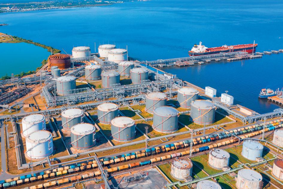

tank’s service life to ensure the tank can withstand the high pressure of hundreds of thousands of gallons of fluid, such as crude oil or refined petroleum products, stored within its walls. At the same time, hydrotest water and the moisture it leaves behind can have a corrosive effect on bare metal surfaces.
The most natural solution is to treat hydrotest water with a corrosion inhibiting additive. One option is to dissolve an amine carboxylate blend of vapour-phase and contact-phase corrosion inhibitors directly in the water. Another option is to use a float coat, which is especially helpful if the hydrotest water will be raised or lowered multiple times. M-645 is a good example of a float coat that rides on the surface of the water while the tank is filled. As the water level rises or falls, this oil-based corrosion inhibitor coats the side of the tank with a protective film. Furthermore, M-645 can be used with saltwater or brine, allowing oil and gas terminals located near the sea to take advantage of abundant seawater for hydrotesting with greater economy but without devastatingly corrosive effects.
Pre-commissioning phase
Another common reason for internal AST protection is that there is often a significant gap between the time a tank is constructed and the time the surrounding plant is commissioned. Periods of layup may also occasionally arise for plant maintenance or shutdown. During these extended times, it is important to protect the inner steel structure to keep it like-new or as close as possible to the original condition. The following two case studies demonstrate some of the different approaches tank owners can take.
Case study one
In one case, three crude oil storage tanks had already been hydrotested but would not be filled with crude oil for 6 - 12 months. VpCI®-329 was selected as the corrosion inhibitor and sprayed on the inner walls of the tank. This wet film contained both direct contact corrosion inhibitors and corrosion inhibitors that would volatilise and diffuse (vapour phase corrosion inhibitors) throughout the space. An advantage was that it was not considered necessary to clean the corrosion inhibitor out of the tank before adding crude oil. This met the tank farm’s desire to maintain immediate readiness for commissioning. 1

3. Inspection, repairs, and other work typically cannot be performed on tanks unless they are drained and out of service. Treatments exist which allow corrosion protection to be applied to AST bottoms in any phase.
Case study two
In another case, a sulfur recovery plant was looking for one year of preservation inside a fixed roof AST. This time, the tank was fogged with VpCI-337, a waterborne vapour phase corrosion inhibitor, and sealed. Periodic inspection and final commissioning confirmed that the preservation had met customer expectations. 2 One advantage of this method is that this water-based product does not leave behind an oily film, making it easier to
Figure
Figure 2. The spaces under AST bottoms are at risk of corrosion but are difficult to access and protect.
Figure 1. Tanks located in coastal environments with exposure to high temperatures, humidity, and chlorides are at higher risk for corrosion.

remove, if necessary, before tank commissioning. Moreover, the vapour-phase action allows the corrosion inhibitors to diffuse throughout the tank void for comprehensive protection coverage without direct application to all metal surfaces.
Protecting tank undersides
One of the biggest AST corrosion challenges lies underneath the tank floor: protecting AST bottoms against soil-side corrosion. This is especially serious in climates such as those in the Middle East, which experience high temperatures, humidity, and even corrosive soil elements. Regardless of the weather, the space underneath the tank is hidden and difficult to reach, making it an excellent environment to trap moisture and foster corrosion. This can lead to serious consequences if left unchecked. Corrosion can thin the tank bottom, shortening its service life and requiring repairs that cannot be performed without emptying the tank, which is expensive and time-consuming. In worst case scenarios, corrosion may deteriorate the metal enough to create a dangerous leak before the problem is noticed.
For years, the industry standard of AST bottom protection has been cathodic protection (CP). This technology redirects the flow of electrons to a sacrificial anode rather than allowing this part of a corrosion cell to form on the main metal structure. Impressed current cathodic protection (ICCP) uses an electric current to do so. The challenge is that ICCP systems rely on a continuous source of power, and the current does not always reach all surfaces of the tank floor, which can become uneven over time.
CorroLogic® vapour phase corrosion inhibitors can be used in conjunction with or in the absence of a CP system. Vapour phase action allows these corrosion inhibitors to travel to all tank bottom surfaces, including pockets unprotected by CP, and
form a molecular protective layer on the metal. Currently, CorroLogic AST treatments come as a powder or a slurry, each of which can be injected underneath an AST floor. Already in use for two decades allowing trial data to accumulate and point to its effectiveness, the generic form of this technology has been added to new industry standards. These include API Technical Report 655, ‘Volatile Corrosion Inhibitors for Storage Tanks’, 3 and AMPP SP21474-2023, ‘External Corrosion Control of On-Grade Carbon Steel Storage Tank Bottoms’. 4
The vapour phase action of this treatment offers flexibility to tank owners, who can apply it during any phase of a tank’s life cycle. CP is easiest to apply before the tank is in use and preferably before it is built. Application only gets harder once the tank is in place and commissioned, since repairs and inspection cannot be made without draining the AST and sometimes raising it – a very costly and time-consuming operation. Where these structural challenges hinder tank operations, CorroLogic can be injected under the tank bottom without disturbing the overhead structure. It can complement CP by filling in unprotected pockets on the tank underside. The only requirement for it to continue functioning is to make sure the area underneath the tank remains closed. An ongoing source of power is not needed, so the solution can serve as a backup to ICCP when/if power is lost.
Concrete bund wall repair and maintenance
Being aware of one’s surroundings is an important safety habit. It is also a good recommendation for AST maintenance and protection. Reinforced concrete bund walls are common in tank farms as a secondary containment precaution in case of tank leaks. Unfortunately, these walls face their own corrosion problems, exacerbated by harsh climates with high temperatures, humidity, and chlorides. Over time, these elements take their toll on concrete and necessitate repair.

Case study three
A Middle East tank farm experienced similar problems and launched a repair programme that included migrating corrosion inhibitors to slow the progression of metal reinforcement corrosion. Similar to vapour phase corrosion inhibitors, migrating corrosion inhibitors form a protective molecular layer on metal surfaces and can
Figure 4. Storage tanks are often surrounded by secondary containment berms to capture fluids in case of a leak. These concrete structures can also be affected by corrosion.


SHORT COURSES: SEPTEMBER 15, 2025
SYMPOSIA: SEPTEMBER 16-18, 2025
GEORGE R. BROWN CONVENTION CENTER | HOUSTON, TX

The Turbomachinery & Pump Symposia is recognized worldwide as the industry’s must-attend event. Connect with over 4,700 delegates, meet with leading suppliers, observe product demos, and get answers to your technical questions.
We look forward to seeing you in Houston!
4,768 ATTENDEES
298 EXHIBITING COMPANIES

HOSTED BY
48 COUNTRIES
migrate through voids. In the case of concrete, these voids are concrete pores, and migrating corrosion inhibitors can be applied as admixtures or surface applied corrosion inhibitors (SACIs). In this particular project, MCI®-2005 admixture was added to 2000 m 2 (2616 yd 2 ) of new concrete to repair damaged areas of the bund walls. Rather than sandblasting rusted rebar that was exposed during the repair, workers applied a rust converting primer to passivate more than 2600 m 2 (3110 yd 2 ) of metal reinforcement. An SACI containing migrating corrosion inhibitors in a 40% silane water repellent was applied over more than 3300 m 2 (3947 yd 2 ) of concrete surface for additional protection. 5 This is an important practice both to inhibit the ingress of additional corrosives and to help balance out the corrosion potential by applying migrating corrosion inhibitors to the entire surface area.
Take up the challenge
Tank protection is important and challenging, but not impossible. Technologies such as float coats, vapour phase corrosion inhibitors, and migrating corrosion inhibitors combine to offer many different avenues of corrosion protection. This allows tank owners to inhibit corrosion during hydrotesting, layup, and even after a tank is in service. Protection is not
limited to the tank itself but is also available for surrounding concrete structures such as bund walls, which play an important secondary safety role. Tank owners who are struggling with their current methods of corrosion protection – or a lack thereof –should consider supplementing traditional methods with those that take advantage of the benefits of vapour phase corrosion inhibitors and migrating corrosion inhibitors. In doing so, it is possible to protect the most difficult to reach areas under the tank while minimising the necessary time and hassle for the work.
References
1. ‘Preservation of New Crude Oil Storage Tanks’, Case History #725, Cortec Corp. (April 2021), accessed 16 January, 2024.
2. ‘Internal Preservation of Aboveground Storage Tanks at Refinery’, Case History #709, Cortec Corp. (2019), accessed 16 January, 2024.
3. ‘Volatile Corrosion Inhibitors for Storage Tanks’, American Petroleum Institute, API TR 655. (28 April, 2021). https://www.apiwebstore.org/standards/655.
4. ‘External Corrosion Control of On-Grade Carbon Steel Storage Tank Bottoms’, AMPP SP21474-2023, AMPP, (2023), https://store.ampp.org/ampp-sp21474-2023-externalcorrosion-control-of-on-grade-carbon-steel-storage-tankbottoms.
5. ‘Fuel Tank Farm Walls Rehab’, Case History #722, Cortec Corp. (2014), accessed 16 January 2024.
Note
Special thanks to Eric Uutala (Cortec Technical Sales and Product Manager – Asset Preservation and CorroLogic) and Lisa Marston (Cortec Project Engineer) for technical review.

A podcast series for professionals in the downstream refining, petrochemical and gas processing industries
LISTEN NOW

EPISODE 1
Alan Gelder, Senior Vice President of Refining, Chemicals and Oil Markets at Wood Mackenzie, provides a review of downstream markets in 2024 and looks ahead to what 2025 may hold for the sector.


EPISODE 2
Dr Klaus Brun, Global Director of Research & Development, Ebara Elliott Energy, discusses the progress that is being made towards adapting centrifugal compressors for high-speed hydrogen compression.


EPISODE 4
Rasmus Rubycz, Market Manager for New Energy at Atlas Copco Gas and Process, considers how heat pumps as an industrial technology are gaining greater attention as a result of the increased drive for sustainability and the challenges and opportunities of electrification of process heat.

EPISODE 3
Peter Davidson, CEO of the Tank Storage Association (TSA), outlines the essential role that the tank storage sector has to play in ensuring supply security and resilience, as well as in facilitating the energy transition.


Sponsored by

EPISODE 5
Mike Logue, Owens Corning Business Director – Specialty Insulation, delves into factors that can support the performance, safety and longevity of insulating systems installed in hydrocarbon processing environments, including cryogenic facilities.
EPISODE 6
Leakhena Swett, President, ILTA, and Jay Cruz, Senior Director of Government Affairs and Communications, ILTA, consider the importance of trade associations and industry collaborations.

STORAGE TANK PURGE SERVICES


• Cryogenic Vaporizers for Liquified Gases
• Portable Enclosed Combustors
• Storage Tank Inert Gas Purging
• Liquid Nitrogen Truck Transports
• Specialization in NH3, LPG, and Natural Gas Tank Purges and Commissioning