
February 2025


rio@register-iri.com


February 2025
rio@register-iri.com
30 From afterthought to advantage
Mark Krajewski and Justin Rispoli, Aspen Aerogels, USA, demonstrate how choosing aerogel insulation drives efficiency and value in LNG asset design.
JP Lacouture, Kpler, USA, provides insight into why Brazilian LNG demand remained modest in 2024, despite an historic drought.
35 A safety (insulation) blanket


Xuan Chi (Damien) Nguyen, Chief Technology Officer, Wison New Energies, China, identifies how floating LNG has developed and progressed over the past decade.
21
Sreeram Krishnan, Zeeco, Inc., explores safety systems for fired equipment in the LNG industry.
Danny Constantinis, Executive Chairman and CEO, EM&I Group, Malta, considers LNG safety culture in the era of artificial intelligence.
Harry Walkoff, Technical Consultant with Alkegen, describes how aerogel insulation technology blankets can provide advanced safety solutions.
39 Dealing with LNG density monitoring
Joe Goodbread, Daniel Brunner, Daniel Lima, Caroline E. Giacomin, and Sunil Kumar, Rheonics, highlight the importance of an LNG density sensor for transit and storage measurements of natural gas in a liquefied and gaseous state.
43 Navigating
the LNG industry
Christopher Goncalves and Li Li, BRG’s Energy & Climate Practice, evaluate the regulatory uncertainties and commercial opportunities of greenhouse gas emissions measurement and mitigation in the LNG industry.
47 Monitor to maximise performance over lifetime
Anna Lazaridou, Ryutaro Sato, Raul Llorens, and Mark Kent, Johnson Matthey, review the full range of performance monitoring methodologies available to operators to ensure that gas purification units are always performing optimally.
53
Alain Hermans, Rockwell Automation, Belgium, looks at how automation solutions can help the LNG industry optimise operations and efficiency.


In support of optimally designed facilities, it is prudent engineers pursue every opportunity for potential weight and space savings. This month’s feature article comes from Aspen Aerogels, a leader in aerogel technology, and covers how insulation selection can impact the outcome of onshore and offshore LNG asset design.
Learn more at www.aerogel.com.


Managing Editor
James Little james.little@palladianpublications.com
Senior Editor
Elizabeth Corner elizabeth.corner@palladianpublications.com
Editor Jessica Casey jessica.casey@palladianpublications.com
Editorial Assistant
Abby Butler abby.butler@palladianpublications.com
Sales Director
Rod Hardy rod.hardy@palladianpublications.com
Sales Manager
Will Powell will.powell@palladianpublications.com
Production Designer Amy Babington amy.babington@palladianpublications.com
Head of Events
Louise Cameron louise.cameron@palladianpublications.com
Event Coordinator
Chloe Lelliott chloe.lelliott@palladianpublications.com
Digital Events Coordinator
Merili Jurivete merili.jurivete@palladianpublications.com
Digital Content Assistant
Kristian Ilasko kristian.ilasko@palladianpublications.com
Junior Video Assistant
Amélie Meury-Cashman amelie.meury-cashman@palladianpublications.com
Digital Administrator
Nicole Harman-Smith nicole.harman-smith@palladianpublications.com
Administration Manager
Laura White laura.white@palladianpublications.com
We’ve (finally) made it through January. After what seemed to be a never-ending month, February is here, and with it comes Valentine’s Day, the 2025 GRAMMYs, the 97th Academy Awards nominations, and, of course, the Super Bowl.
The championship game of the NFL is scheduled to be played on 9 February 2025 at the Caesars Superdome in New Orleans, Louisiana. The game will be played between the American Football Conference (AFC) champion and two-time defending Super Bowl champion, Kansas City Chiefs, and the National Football Conference (NFC) champion, Philadelphia Eagles. This game is a rematch of Super Bowl LVII from 2023 in which the Chiefs defeated the Eagles 38 – 35; the Chiefs are now just one win away from becoming the first team to three-peat in the Super Bowl era.1
The Chiefs are not the only ones making an historic return in the US this year; President Donald Trump has also returned to office in Washington D.C. to serve a second term. Despite not being in office for long, he has already issued a wave of orders, including the reversal of Biden’s pause on LNG exports to free trade agreement countries and directing the U.S. Department of Energy to “unleash American energy dominance”.2
LNG companies in the US have praised Trump’s decision to lift the freeze on export permits, with three companies developing LNG projects in Texas and Louisiana, including Cheniere Energy, Commonwealth LNG, and Energy Transfer, announcing they will move their projects ahead with full speed following this reversal.3 Trump’s decision could enable almost 100 million tpy of additional LNG from significantly-advanced projects by 2031, which would further establish the US as the world’s largest LNG exporter.
On the other hand, it remains to be seen if a potential future lack of studies on the environmental impacts of new LNG projects coupled with new EU regulations such as the EU Methane Regulation will cause any issues for the US LNG industry.
Trump’s “Drill, Baby, Drill” energy mandate, promoting the exploration and export of US energy resources, also provided the foundation for a heads of agreement between the Government of Bangladesh and Louisiana-based Argent LLC for the purchase of up to 5 million tpy of LNG.4 The agreement underscores a growing energy collaboration between the two nations, and will help Bangladesh, and the wider South and Southeast Asia region, with their energy transition efforts by reducing reliance on high-carbon fuels.
LNG also plays an important role in Brazil’s energy mix, used as a ‘backstop fuel’ to help aid with a lack of power generated from hydropower during periods of server droughts. Kpler’s regional report at the beginning of this issue provides insight into why Brazilian LNG demand remained modest in 2024, despite an historic drought.
Finally, you can pick up a copy of this February issue at The 11th International LNG Congress 2025 in the Netherlands from 10 – 12 March, and StocExpo, also in the Netherlands, from 11 – 12 March.
1. DEARDO, B., ‘Chiefs’ pursuit of three-peat: Here’s how three previous back-to-back champs fared in conference title game’, CBS Sports, (19 January 2025), www.cbssports.com/nfl/news/chiefs-pursuit-of-three-peat-heres-howthree-previous-back-to-back-champs-fared-in-conference-title-game/
2. ‘U.S. Department of Energy reverses Biden LNG pause’, U.S.Department of Energy, (21 January 2025), www. energy.gov/articles/us-department-energy-reverses-biden-lng-pause-restores-trump-energy-dominance-agenda
3. WILLIAMS, C., ‘LNG companies hail Trump decision to lift freeze on export permits’, Reuters, (22 January 2025), www.energy.gov/articles/us-department-energy-reverses-biden-lng-pause-restorestrump-energy-dominance-agenda
4. ‘Bangladesh signs landmark LNG deal under President Trump’s energy policy initiative’, Bangladesh Investment Development Authority, (25 January 2025), https://bida.gov.bd/details/bangladesh-signslandmark-lng-deal-under-president-trumps-energy-policy-initiative

Trust Ebara Elliott Energy for comprehensive global turbomachinery service and support.
Ebara Elliott Energy’s renowned global service organization delivers expertise, skills, and capabilities with all types of rotating equipment, including emergency support, spare and replacement parts, repairs, periodic inspections, and equipment drop-in replacements, rerates, upgrades, and modifications. Our strategic service locations around the world enable us to expertly serve customers wherever they are at the time they need us most.
Learn more about our range of service capabilities at elliott-turbo.com.
Trusted solutions for a sustainable future.

Tamboran Resources Corp. and Santos Ltd have entered into a non-binding memorandum of understanding (MoU) to undertake technical studies relating to a potential Darwin LNG (DLNG) Train 2 expansion and collaborative work on the jointly-owned EP 161 acreage (Santos 75% operator, Tamboran 25%) in the Beetaloo Basin.
The goal of the studies is to evaluate options for supplying natural gas to a potential expansion train at the existing DLNG facility at Middle Arm. DLNG was approved to a nominal 10 million tpy of LNG, with this expansion opportunity up to ~6 million tpy.
Santos is the operator of the existing DLNG project with a 43.4% working interest.
Tamboran and Santos are joint venture partners in the EP 161 acreage which holds ~300 000 acres of Mid Velkerri B Shale at depths below 8850 ft (~2700 m).
The region has demonstrated Marcellus Basin-type decline curves from two Tanumbirini wells that were drilled and flow tested in 2022.
Tamboran remains committed to progressing the development of the proposed NTLNG project at Middle Arm, which is currently undergoing pre-FEED studies with Bechtel Corp.
The 45 000 m3 LNG carrier, LNG Jia Xing, has completed its first-class survey after five years of operation with an LNT A-BOX containment system.
The LNG Jia Xing was the first vessel to install the LNT A-BOX technology in 2020, when the medium-sized LNG carrier was delivered from China Merchants Heavy Industries (Jiangsu) Co., Ltd.
LNT A-BOX is a cargo containment system for safe, reliable storage and transportation of LNG and other liquefied gases in bulk. It is a robust and flexible system, based on IMO Tank Type A, featuring benefits such as mitigation of sloshing, no tank filling restrictions, and easy access to both primary and secondary barriers.
LNT Marine, which has developed the LNT A-BOX technology, attended the five-year class dry-docking and renewal survey together with the shipowner, ship management company, and the vessel’s classification company, China Classification Society.
The five-year classification survey was conducted at Yiulian Dockyards, Shekou. The witnessing confirmed that the primary barrier (cargo tank) remains in excellent condition with no fatigue nor leaking issues, and zero gas alarms over the five-year operation time span. The secondary barrier and insulation system were fully inspected and quality assured including global tightness testing with no complications.
Integrated Maritime Management, has carried out ship-to-ship operations and the vessel has transported LNG on various filling levels in the tanks and experienced zero problems over the past five years.
Portsmouth International Port has completed the first bunkering transfer of LNG at the port.
The Saint-Malo, the first of two new electric-hybrid ships from Brittany Ferries soon to be entering service from the city, took on LNG fuel from the Optimus, a bunkering barge operated by Titan Clean Fuels.
Titan was issued a permit to perform LNG bunkering operations at Portsmouth International Port earlier this month, following a long-term agreement signed between
the Dutch company and Brittany Ferries, for the supply of the cleaner fuel. LNG bunkering is now available to all customers sailing into and out of Portsmouth International Port. LNG emits significantly lower levels of harmful particulates compared to usual heavy marine fuel oils, which leads to an improvement in air quality for residents. LNG also allows for the blending in of bio-LNG derived from organic waste at any proportion requested, offering further decarbonisation options to the shipping industry.

The U.S. Department of Energy (DOE) has ended the LNG pause and returned to regular order following direction given by President Donald J. Trump. The Office of Fossil Energy and Carbon Management (FECM) has been directed to resume consideration of pending applications to export American LNG to countries without a free trade agreement with the US in accordance with the Natural Gas Act. Proper consideration of LNG export applications is required by law and shall proceed accordingly.
In December 2024, the Department published a multi-volume analysis of selected issues concerning LNG exports and established 18 February 2025 as the deadline for public comments of the study. To ensure such public interest determinations receive appropriate stakeholder input, the Department is extending the comment period from 18 February 2025 to 20 March 2025.
Acting DOE Secretary, Ingrid Kolb, has directed the FECM to return to regular order and resume consideration of all applications. This process should occur simultaneously with the multi-agency NEPA review process to streamline and reduce inefficiencies in the regulatory process.
Y PF has signed a memorandum of understanding (MoU) with India's Oil and Natural Gas Corp. (OIL), Gas Authority of India Ltd (GAIL), and Oil and Natural Gas Corp. Videsh Ltd (OVL) for the export of LNG with an estimated target of up to 10 million tpy. Additionally, the agreement includes co-operation on lithium and other critical minerals, as well as the exploration and production of hydrocarbons.
The signing ceremony in New Delhi was attended by the Minister of Petroleum and Natural Gas, Hardeep Sinh Puri; the Secretary of Petroleum and Gas, Pankaj Jain; OIL's Executive Director of Business Development, Ranjan Goswami; GAIL's Executive Director of LNG, Satyabarata Bairagi; OVL's Vice President of Business Development, Swati Sathe; and YPF's President and CEO, Horacio Marín.
The Government of Bangladesh has signed a transformative heads of agreement (HOA) with Louisiana-based Argent LLC for the purchase of up to 5 million tpy of LNG.
US President Donald Trump’s “Drill, Baby, Drill” energy mandate, promoting the exploration and export of US energy resources, provided the foundation for this agreement. The deal was signed by Ashik Chowdhury, Executive Chairman of BIDA, and Jonathan Bass, Chairman and CEO of Argent LNG, in a ceremony at the Bangladesh Embassy in Washington D.C. on 24 January 2025.
The agreement underscores growing energy collaboration between the two nations, reflecting Bangladesh’s role as a rising economic force in South and Southeast Asia and the US’s position as a reliable supplier of clean energy. It is also expected to contribute to global energy transition efforts, reducing reliance on higher-carbon fuels while fostering economic growth.
X JERA Global Markets and ADNOC Gas sign multi-year LNG supply agreement
X Stolt-Nielsen to purchase shareholding in Avenir LNG Ltd
X Bureau Veritas supports final delivery of CIMC SOE's third LNG bunkering vessel
Follow us on LinkedIn to read more about the articles www.linkedin.com/showcase/lngindustry


In the oil and gas industry, ensuring highest safety and plant availability is crucial, while achieving decarbonization goals has also become a critical imperative. Our comprehensive portfolio and expertise enable process improvements that increase operational reliability and move us towards net zero targets.

10 – 12 March 2025
The 11th International LNG Congress (LNGCON) 2025 Amsterdam, the Netherlands https://lngcongress.com
11 – 12 March 2025
StocExpo 2025 Rotterdam, the Netherlands www.stocexpo.com
07 – 08 April 2025
7th Global LNG Forum Barcelona, Spain https://lng-global.com
19 – 23 May 2025
29th World Gas Conference (WGC2025)
Beijing, China
www.wgc2025.com
27 – 28 May 2025
6th American LNG Forum Texas, USA
https://americanlngforum.com
10 – 11 June 2025
Gas, LNG & The Future of Energy 2025 London, UK www.woodmac.com/events/ gas-lng-future-energy
09 – 12 September 2025
Gastech Exhibition & Conference Milan, Italy
www.gastechevent.com
16 – 18 September 2025
Turbomachinery and Pump Symposia 2025 Texas, USA
https://tps.tamu.edu
Bahía de Bizkaia Gas (BBG), an LNG storage and regasification facility located in the Port of Bilbao, has welcomed the docking of its 1000 th LNG tanker, the Rioja Knutsen, chartered by Naturgy.
The Rioja Knutsen docked at the BBG dock in the early hours of 20 January 2025 from the US, carrying 164 000 m 3 of LNG. It is an Atlantic Max 2G type liquid natural gas tanker, capable of transporting liquefied gas in its cryogenic holds that must remain at a temperature of -163˚C. Belonging to Knutsen OAS Shipping, the ship has an overall length of 290 m and a width of 46.4 m. It was built in 2016 in South Korea and sails under the Spanish flag.
BBG has a total storage capacity of 450 000 m3 of LNG, with three storage tanks with a capacity of 150 000 m3 each, and its regasification capacity is 800 000 Nm3/h.
As a result of comprehensive expansion consisting in increasing the number of submerged combustion vaporisers (SCV) regasifiers, and building a second quay and a third tank for process storage of LNG, the regasification capacity of the LNG terminal in Świnoujście has amounted to 8.3 billion m 3/y since 1 January 2025.
The expansion of the terminal implements one of the key goals of the country's Energy Policy, which refers to the diversification of sources and directions of natural gas supply. Thanks to the terminal, Poland has the ability to import gas from various parts of the world in liquefied form and then, after regasification, send it through gas pipelines into the country and beyond the borders. In 2015, the capacity of the LNG terminal in Świnoujście, as an entry point to the national transmission system, was 5 billion m 3/y. From 1 January 2025, the terminal's regasification capacity is 8.3 billion m 3 and corresponds to almost 50% of the annual demand for gas from domestic customers.
The facility expansion programme was divided into two stages. The first stage consisted in increasing the operating parameters of the existing regasification installation, including by installing two more SVC, regasifiers, and a measurement line. As a result of these activities, from January 2022, the terminal was able to provide regasification services, with a capacity of 6.2 billion m 3 .
As part of the second stage, a third tank and a second quay for unloading, loading, and bunkering LNG were built, along with a transmission viaduct connecting the quay installations with the new tank. The task of these facilities is to improve the flexibility of the terminal's operation and increase operational capabilities, including receiving larger volumes of LNG gas supplies and bunkering, i.e. refuelling ships with LNG directly at the quay. Thanks to the construction of these facilities, the LNG terminal in Świnoujście achieved regasification capacity of 8.3 billion m 3/y.
The investor in the construction of the hydrotechnical part of the quay, i.e. the ship berth, the marine structure of the transmission viaduct and the mooring infrastructure was the Szczecin and Świnoujście Seaports Authority.


JP Lacouture, Kpler, USA, provides insight into why Brazilian LNG demand remained modest in 2024, despite an historic drought.
razil is typically a seasonal importer of LNG, bringing in volumes predominately to offset declines in hydropower generation. On average, Brazil usually imports around 2 million tpy of LNG, mostly during the dry season, to provide feed stock for thermal power facilities. However, every few years,


Brazil experiences drought conditions that greatly increase the need for thermal power generation. In 2024, Brazil endured a severe drought that saw a massive reduction in reservoir levels. However, while LNG imports grew slightly y/y, they failed to reach the levels seen in previous, similarly intense droughts.
Prior to 2024, Brazil’s most recent drought period took place in 2021. Between March – August 2021, monthly hydropower generation dropped from 41 000 GWh to 24 500 GWh, the largest seasonal loss in over 10 years. To help compensate, monthly thermal


generation increased from 7000 GWh to 14 500 GWh in the same period. Brazil was forced to increase its imports of LNG, diesel, and fuel oil to plug the gap caused by decreasing hydropower output. The 2021 drought led Brazil to bring in a record 7 million t of LNG for the year.
In the three years since the 2021 drought, there has been considerable development of LNG import infrastructure. Since 2021, four new regasification terminals have been built in Brazil, increasing import capacity from 23 million tpy to over 45 million tpy. Most of these projects are LNG-to-power initiatives designed to supply natural gas to areas unable to access domestically produced gas. In previous years, these areas would rely on dirtier, potentially more expensive thermal power feed stocks such as fuel oil, diesel, or coal during periods of low hydropower output.
Brazil’s next drought took place in 2024, which proved similarly intense to 2021. Brazil’s monthly hydropower generation was at a record high of 45 500 GWh in March 2024, but historically low rainfall reduced output to nearly 28 500 GWh by September 2024. This 17 500 GWh decrease was roughly 10% greater than the loss of hydro generation seen in 2021. However, despite the massive reduction in hydropower and the substantial buildout of regasification capacity, Brazil only imported small quantities of LNG in 2024. Overall, Brazil imported 2.7 million t of LNG in 2024, leading to only 6% utilisation of Brazil’s increasingly large regasification terminal fleet.

Ultimately, what allowed Brazil to limit its LNG imports during the 2024 drought was a massive buildout of solar and wind generation capacity over the last three years. Of the roughly 26 GW of new power generation capacity installed in Brazil since 2021, 49% has been wind and 41% has been solar. The expansion of wind generation has been particularly impactful, as wind power tends to have its strongest output during the dry season, when hydropower is at its lowest.
Over 90% of the new solar and wind generation capacity has been installed in the northeastern region of Brazil. The northeast has historically relied more on thermal power than other regions, as it has the lowest levels of hydropower generation in Brazil.


LNG has long been used to bolster baseload power generation in the northeast, while LNG was mostly imported into other regions only during acute hydropower shortfalls.
With the addition of the new renewables capacity, the region has been able to greatly reduce the amount of thermal generation in its power mix while also increasing overall electricity generation. This growth in electricity generation has not only allowed for northeastern Brazil to import far less LNG but also enabled the region to export excess power to southeastern Brazil. Given that southeastern Brazil is the second-largest LNG importing region, this is further decreased nationwide LNG demand.
Renewables generation is set to continue growing in Brazil. Of the 17 GW of capacity currently under construction, roughly 50% is wind and solar. Perhaps more notably, wind and solar projects comprise roughly 99% of the 147 GW of planned, pre-construction projects in Brazil. This massive expansion of renewables will limit growth in LNG demand, despite the continuing buildout of regasification capacity.
LNG projects in the southeastern and southern portions of Brazil will also compete with increasing domestic production and pipeline imports. With the Rota-3 pipeline having partially entered service in 2024, southeastern and southern Brazil will have increased availability of domestic natural gas supply from the prolific pre-salt deepwater oil fields. Once the project is fully online, it will be capable of delivering roughly 625 million ft 3 /d of associated gas to the Brazilian pipeline grid.
Additionally, several contracts have been signed recently between natural gas producers in Argentina and buyers in Brazil. These agreements will see natural gas delivered to Brazil by two possible routes. The first is via the currently unutilised cross-border pipeline between the two countries that was originally designed to supply the Uruguaiana gas-fired power plant in Brazil. The other path involves bringing Argentine pipeline gas to northern Argentina, into Bolivia, and ultimately into Brazil via the GASBOL pipeline. The second path is made possible by a recent project to reverse the previously southbound TGN pipeline in Argentina to allow for domestically produced gas to displace Bolivian pipeline imports in the northern portions of the country.
Most of Brazil’s future LNG demand is expected to come from projects like the Barcarena terminal, located in a more remote region of the country and underpinned by a long-term supply contract with an industrial customer. Those projects looking to provide gas directly to the gas pipeline network may face strong competition as thermal power requirements continue to decline with renewables growth and other sources of natural gas become more available. Though LNG looks to remain a relatively marginal fuel in Brazil, it will still likely serve an important purpose as a backstop fuel when other sources of power generation are disrupted or limited.
Xuan Chi (Damien) Nguyen, Chief Technology Officer, Wison New Energies, China, considers how floating LNG has developed and progressed over the past decade.
ince Wison New Energies’ first floating LNG (FLNG) was commissioned in 2015, the company has been a leader in FLNG development – it started a core programme in 2020 to launch its First Generation FLNG standard design using modular blocks, pre-allocating utilities and process systems in topsides’ modules and hull machinery space.
The locations considered for Wison’s standard FLNG included West Africa, East Africa, South America, North America, the Mediterranean Sea, the South China Sea, and Australasia.
An investigation was made into the largest potential area for FLNGs to be deployed, including at-shore, near-shore and offshore applications, feed gas composition (lean/rich), metocean conditions, meteorological conditions, geophysical and geotechnical conditions, and local regulations.
The main interfaces between the accommodation, machinery spaces, mooring, cargo tanks, topside modules, laydown areas, and material handling are pre-defined, and the overall arrangement follows an inherently safe design.
A key factor was the evaluation of different liquefaction technologies, where Wison compared liquefaction efficiency, equipment counts, weight, footprint, and suitability for offshore feasibility, operability, and maintainability.
The mooring system study included jetty mooring, shallow water single point mooring, deepwater single point mooring, external turret vs internal turret, and permanent vs disconnectable moorings.
The topside module design concept is based on process functionality, where each module is designed independently by its function.
For liquefaction technology, Wison selected the Chart Industries IPSMR® process. Chart has performed several rigorous studies to benchmark the performance of IPSMR relative to other liquefaction processes and has consistently found that IPSMR has comparable efficiency to C3MR and is significantly more efficient than conventional SMR processes. The design permits up to three trains, hence allowing a total capacity of 1.2, 2.4, or 3.6 million tpy.

The hull is based on the use of robust SPB tanks, which are built in Wison’s workshops in parallel with the FLNG hull and enables a schedule acceleration compared with the use of membrane tanks. Gas trials can be performed in the Wison shipyard, which greatly reduces the risk of on-site commissioning and start-up problems for FLNG projects.
Moreover, with Wison undertaking the full EPCIC scope for both the topsides and hull, the company can achieve seamless integration of the complete FLNG, drawing on a proven track record of FLNG project execution.
Wison’s standard FLNG solution also provides flexibility for various liquefaction capacities and has an appealing delivery timeline. Additionally, through partnerships with key equipment suppliers, Wison can quickly place orders for essential equipment.
Thanks to this core programme, it takes only a short time to adapt the standard Generation 1 FLNG design to meet a client’s specific FEED package for the EPC stage.
Currently, two FLNGs are being built based on this core programme.
The Generation 2 FLNG (rolled-out at Gastech in 2024) is the next evolution of the core programme. The objective of Generation 2 is to provide the market with a solution, which has the potential to achieve around a 35% reduction in emissions over Generation 1.
There are two main drivers for reducing emissions. Firstly, project finance is becoming much harder to source for hydrocarbon projects, with financial institutions being very selective on which projects to support (if any). To obtain support, projects must demonstrate leading performance in terms of emission reduction.
Secondly, stakeholder pressure to address climate change is growing both internally from company staff, and externally from a range of a wide range of bodies.
The Generation 1 FLNG design has a conventional level of carbon dioxide equivalent (CO2-e) emissions, at around 0.26 t CO2-e/t LNG (excluding the CO2 removed from feed gas in the AGRU).
Wison has further developed this concept into a new Generation 2 FLNG design, which can deliver a significant reduction in emissions. This is achieved by implementing four key changes to the Generation 1 concept:
z More efficient gas turbine drives for the refrigerant compressors like the LM9000.
z Inlet air chilling is used to further improve the efficiency of the gas turbines in the central power plant, depending on the seasonal ambient air temperature profile swings.
z A central combined cycle power plant significantly reduces the CO2 emissions, and also brings an improvement in reliability and availability, benefiting the project economics.
z Dual fuel engines located in the hull replacing the gas turbine power generators used in the Generation 1 FLNG.
However, the final choice of the options applied from the pre-engineered catalogue will be a project-specific decision,
A supplement to LNG Industry

Distributed at

Our North American supplement is returning soon!
This special issue will focus on LNG activity in the US, Canada, and Mexico, with keynote articles, case studies, and more.
depending on the feed gas composition, site location, and client requirements.
Wison’s Generation 2 FLNG design has also applied best practices to ensure that it will remain cost-competitive, with a low project execution risk. To achieve this, the company has:
z Used a rigorous technology readiness level (TRL) process to identify the main risks and the mitigations needed to ensure safe, efficient, and robust performance offshore.
z Formed strong partnerships with leading equipment suppliers, such as Baker Hughes for the main rotating equipment, and Chart Industries for the liquefaction license and its cold boxes.
z Integrated the project learnings in the two Wison fabrication yards from the Generation 1 FLNG projects, to optimise the design for improved constructability and commissioning.
Wison has evaluated mature and proven technologies and embedded them in the Generation 2 FLNG design. Switching from an ‘n+1’ gas turbine power generator configuration to an ‘n’ gas turbine plus 1 steam turbine can reduce emissions from the power generation system by around 25 – 30%.
Lager capacity LNG trains offer higher efficiency, and hence lower fuel gas consumption per tonne of LNG product. The IPSMR process used for the Generation 1 FLNG designs is rated at 1.2 – 1.4 million tpy per train. This can be increased to around 2 million tpy per train by using the largest gas turbine driver and BAHX cold box available on the market.
Gas turbine efficiency and power output decrease as ambient air temperature rises. This is because warmer air has a lower mass flow rate, leading to less power being generated.
Inlet air chilling helps alleviate this problem. Using evaporative coolers or mechanical chillers to control the air inlet temperature at an optimum value means gas turbine efficiency and fuel gas demand can be minimised, with a corresponding impact on emissions.
A proven solution to routine gas flaring is the ‘closed flare’ design. This uses a high-integrity valve or valves (with a bursting disc bypass) and a recycle compressor to return all purge gas, vented process gas, and any gas leakage (such as from pressure safety valves and blowdown valves) to the main process system.
Refrigerant compressor power can be reduced if the compressed gas is cooled to lower temperatures inter-stage. By using these techniques, refrigeration compressor power can be reduced by around 5%, with a corresponding reduction in fuel gas demand and hence emissions.
The use of high-temperature thermal oil as a heating medium fluid can enable the maximum amount of heat to be recovered from the refrigeration compressor gas turbine exhaust for use in the gas pre-treatment process. Depending on the feed gas composition, this can help eliminate the need for any supplemental fuel gas demand for process heating.
Piping flanges, valve stem seals, and instrument tubing joints are all sources of small gas leaks to the atmosphere. These may be too small to trigger the gas detection systems, but can be a significant source of fugitive methane emissions when accumulated.
The use of advanced digital tools and artificial intelligence can improve plant uptime and reduce the number of process upsets, trips, and restarts, reducing the amount of gas flared.
The latest digital tools can help also to reduce the number of plant trips, leading to a reduction in flaring, which is a significant contributor to total plant emissions.
In one case, the FLNGs indirect seawater cooling system had the potential for adverse effects on marine resources and habitat, so to address the possible seawater temperature rise the FLNG process cooling system was configurated with a high-efficiency air cooling alternative.
To address compliance to more stringent environmental standards, the project compared several combinations of drivers for power generation and critical process compressors (the booster compressor and mixed refrigerant compressors).
The analysis shows a significant improvement in specific emissions intensity of around 35% in favour of Generation 2. The main reduction comes from the selection of combined cycle gas turbine (CCGT) with the addition of a 16 MW super turbo generating for power recovery. The selection of high-efficiency DF engines (located within the hull machinery space) and refrigeration compressor drivers also has a significant positive impact on the overall auto-consumption and the global CO2 emissions of the unit.
In terms of TRL, all the equipment selected for the Wison Generation 2 FLNG is mature and suitable for use on the project with tolerable levels of risk.
Beyond the proven technologies deployed in the Generation 2 FLNG, the company is actively studying other emerging technologies for the future Generation 3 FLNG, to further reduce emissions towards the goal of a near-zero emission FLNG.
For Generation 3, Wison is considering an ‘all-electric’ FLNG concept, using a much larger CCGT power plant and electric drives for the MRCs.
In the last 10 years, there has been a growing trend for onshore LNG plants to use electric drives for the main refrigerant compressors, with power supplied from a high-efficiency on-site CCGT power plant, or from a local power grid.
This scheme requires electric motors in the range of 30 – 65 MW, which Wison does not consider proven technology on floaters. Hence, this solution requires close collaboration with motor suppliers to qualify large motors.
Coupled with this, there is a need for large capacity variable frequency drives (VFDs) with the associated space, weight, and maintenance implications. This needs further analysis to fully qualify such large-capacity VFDs offshore.
The impact of adopting this large motor drive technology would be around a 30% reduction in MRC fuel gas demand, and hence CO2 emissions, linked to the use of the large capacity CCGT power plant.

As a case study, two high-capacity liquefaction technologies were closely examined. One uses electric motors on an all-electric FLNG, while the other uses gas turbines that operate efficiently in an open cycle. Several key factors for each set up were compared.
z Unit capital cost (UCC), US$/million tpy LNG.
z Greenhouse gas (GHG) intensity, t CO 2e/t LNG.
z Lifecycle cost, US$/million Btu.
The evaluation of greenhouse gas intensity showed that the e-Drive with centralised CCGT produces 25% less emissions compared to the alternative. Additionally, the operational costs (OPEX) for e-Drive are about 14% lower than the other option.
With the evaluation of CAPEX, OPEX, and GHG emissions, lifecycle cost can be calculated based on pricing CO 2 emissions at an average mid case for future indicative market forecasts at around US$75/t CO 2 in 2030.
Whilst the UCC for the e-Drive with CCGT is slightly higher (around 6%) than for the alternative concept with open cycle gas turbine, the life cycle costs are around 10% lower (US$0.16/million Btu), which is driven by.
z Greater availability.
z Lower OPEX.
z Improved fuel efficiency.
z Lower greenhouse emissions with a more efficient combined cycle power generation system.
Based on these factors, it was concluded that an all e-Drive concept could be specifically attractive for clients who are driven by life-cycle costs and GHG intensity.
To achieve greater emissions reductions, carbon capture and storage (CCS) can be used. In this case, post-combustion CCS would capture 90% of the CO 2 from the exhaust of CCGT and either send it through an export pipeline or inject it into a nearby geological site. More development is needed before a full scale CCS unit can be implemented on a global FLNG project, but it may be possible by 2030. Table 1 summarises the trend in emissions reductions.
FLNG technology is constantly developing and improving. Options such as the technologies for Generation 2 FLNG are affordable and, in this case, can reduce CO 2 emissions for about US$25 – US$50/t, thus considered low risk because they are reliable and well-tested. For Generation 3, achieving greater emissions reductions will cost more, up to US$100/t.
Wison plans to introduce these new technologies carefully by following a strict assessment process, ensuring that they can reduce emissions without significantly raising project risks.

Sreeram Krishnan, Zeeco, Inc., explores safety systems for fired equipment in the LNG industry.
ired equipment can be found in most operating facilities around the world, regardless of the industry. Technically, fired equipment is defined as any device that combusts fuel to generate heat or energy. This article will specifically focus on three types of fired equipment commonly used as safety, process, or emissions control devices within the LNG industry: flares, incinerators, and fired heaters.
Each of these combustion devices can be utilised in a variety of different LNG applications, from upstream natural gas production and liquefaction to downstream transportation, storage, and regasification. Despite their numerous uses, fired equipment does tend to have a reputation for being among the more specialised and complex units within any operating facility.


Still, their fundamental design principles are actually very simple. Even the name ‘fired equipment’ is pretty straightforward – fire is literally used to operate the equipment.


Although the word ‘fire’ can have negative connotations in the plant operations and maintenance world, fired equipment systems are some of the safest units within any operating facility. This article will address the specific engineering codes, standards, and safety features commonly implemented into the design of flares, incinerators, and fired heaters within the LNG industry. It is also important to have the ability to distinguish between these three major types of fired equipment items, so this article will highlight the similarities and differences between each one. Although they are used in similar applications, these combustion devices differ in overall design, performance, and operation.
When driving by an LNG plant at night, it might be possible to see a reddish-yellow flame seemingly suspended in the air – the source of this flame is most likely an elevated flare.
There are a wide variety of flare systems that can be found in petrochemical plants and LNG facilities around the world. Still, the most common are elevated flares, multi-point ground flares (MPGF), and enclosed ground flares (EGF). In general, flares are considered the most responsive and versatile type of fired equipment compared to an incinerator or fired heater. Flares boast significantly higher turndown rates and can also combust and destroy a sudden, large volume of volatile gases or liquids at destruction removal efficiencies (DRE) of 98% or greater. For those reasons, flares are commonly used as backup or emergency pressure relief devices at an LNG plant or operating facility to protect plant assets and personnel.
Two critical design features must be considered for a flare – a continuous purge and a safe and reliable pilot and ignition system. Nitrogen or fuel gas must be continuously purged through the flare and header piping to prevent oxygen ingress, which could potentially result in an inadvertent accumulation of highly flammable gases inside the flare header. If the flare’s pilot ignites these gases, a flashback or explosion event could occur, posing additional risks to plant personnel and surrounding equipment. A safe and reliable pilot and ignition system is equally as important as a flare’s continuous purge because the pilot system ensures a continuous and stable pilot flame is maintained at all times. If the pilot flame is extinguished and an emergency flaring event occurs, hazardous waste vapours from the upstream process could be vented to the atmosphere without being properly combusted and destroyed. Those vapours could be highly explosive and toxic in nature, which could pose additional safety risks to plant personnel and nearby residents.
In order to prevent flame failure, ZEECO® flare pilots have been developed and tested under the most severe global weather conditions to ensure that they can produce and maintain a continuous and stable flame at all times – even in hurricane-level winds and rain. Flame detection devices such as thermocouples and the ZEECO VerifEyeTM system are most commonly used to detect and confirm the presence of the flare’s pilot flame. However, more complex devices such as the ZEECO FlareGuardianTM and ViZionTM can be used to detect both the flare’s pilot and primary flames. These devices can also monitor and control key performance metrics such as combustion efficiency and smoke opacity.
It is also common for a flare to be equipped with an ignition and control system certified for use within a Class I, Division II hazardous area and designed per API-521 and 537 standards, providing plant personnel with inherently safe methods to ignite and operate the unit. Additional safety devices, such as detonation


or deflagration arrestors, can also be implemented into the design of a flare system. However, these items are not as crucial as the others already discussed. That said, it is important to evaluate the overall necessity of these devices for every flare application based on its individual process and supply conditions.
People often wonder whether there is a difference between an incinerator and a thermal oxidiser, but these terms are used interchangeably to describe the same type of fired equipment. It can be difficult to identify an incinerator in broad daylight, let alone at night. Unlike the exposed flame of an elevated flare, an incinerator’s flame is enclosed and is not externally visible during operation, making it hard to distinguish within any given refinery or LNG plant.
Incinerators are typically regarded as the most complex and highly automated fired equipment devices in comparison to a flare or fired heater. While incinerators are not as responsive as a flare, they are capable of combusting and destroying multiple continuously generated gas or liquid feed streams at very high temperatures, allowing them to boast impressive DREs of 99.9999% or higher. Incinerators are also commonly supplied with an NFPA-86 compliant controls and instrumentation package and a burner management system (BMS) with a programmable logic controller (PLC) that governs the unit’s purge, ignition, heat-up, waste introduction, and shutdown sequence. NFPA-86 standards serve the same general purpose for incinerators that API-537 standards do for flares – providing plant personnel with inherently safe and easy methods to operate the unit without assuming additional risks.
One of the most critical safety features stipulated by NFPA-86 is the pre-ignition purge, which removes potentially combustible compounds from the incinerator prior to ignition. Flame scanners are a common safety feature that verifies the presence of both the pilot and main burner flames during ignition and after waste introduction. Blower/fan run signals, combustion air flow switches, and setpoint temperature and fuel pressure trips are also critical safety features that are governed by NFPA-86 and are commonly implemented into the incinerator’s BMS to further ensure personnel and equipment safety.
Some of the largest and most complex incinerator systems worldwide are found at natural gas liquefaction plants. These systems can be equipped with a wide range of post-combustion treatment devices that enable the incinerator to comply with more stringent SOX, NOX, and CO air permitting requirements. It is also common for these systems to be supplied with waste heat recovery units (WHRU) that utilise hot flue gases from the incinerator to reduce overall fuel consumption and generate utilities required for downstream LNG processes.
Complex incinerator systems provide the end user with a significant number of benefits but come at a price. Larger and more diverse equipment packages are usually governed by more stringent engineering codes and standards to further ensure the safety of personnel and equipment, which is why they are commonly assigned with a safety integrity level (SIL) 2 or 3 classification following completion of the process hazard analysis (PHA) or hazard and operability study (HAZOP). Post-combustion treatment devices and WHRUs usually contribute to higher internal static operating and design pressures that commonly require more stringent mechanical and structural design criteria, such as those listed in ASME Section VIII and Section I design codes. It is also common for blowers/fans within these systems to be designed per API-560 or 673 standards, which require a higher level of margin on both design flow rates and pressures, and require additional instrumentation items for monitoring and control purposes. Keep in mind that while these design codes and standards are not necessarily applied to all complex incinerator systems within the LNG industry, every system should be evaluated based on its specific application and service.
Fired heaters are very similar to incinerators in design and overall complexity and are also commonly used in downstream LNG processes, such as glycol dehydration and regasification.
This type of fired equipment combusts fuel within a radiant section to generate hot flue gases that transfer heat into a series of tubes or coils within the convective section. These coils typically contain a liquid heat-transfer fluid such as Therminol®, which is eventually distributed to various downstream LNG processes. It is also possible for fired heaters to combust waste byproducts from other processes, but unlike an incinerator, they are usually limited to a single exothermic waste gas that only accounts for a maximum of approximately 10% of the total system’s heat release. This is done to ensure that a continuous and stable burner flame is maintained at all times. Flue gases at the outlet of a fired heater are discharged to the atmosphere at DREs of 99.9% or greater, and, like an incinerator, fired heaters can be equipped with selective catalytic reduction to further reduce NOX emissions if needed.
Fired heaters are typically designed per API-560 standards and are usually supplied with an NFPA-87 compliant controls and instrumentation package and BMS PLC. Although NFPA-87 is specifically geared to fired heaters, it is similar to NFPA-86 – they both address the same general sequences and safety requirements, with a few differences. Skin-type thermocouples are additional safety devices that are commonly installed onto tube coils within the fired heater. These devices are used to monitor tube coil temperatures to prevent them from overheating or rupturing,
which could result in an unsafe and unplanned release of hazardous hydrocarbons. Differential pressure transmitters can also be used for similar reasons – they reduce the overall likelihood of overpressure events within the fired heater casing that could result in the unplanned release of hazardous hydrocarbons.
Additional controls and instrumentation items can be implemented into a fired heater’s BMS to further ensure personnel and equipment safety. For instance, oxygen analysers can be used as trim control devices to ensure that a minimum oxygen level is always maintained within the unit (usually ≥3 vol. %). Combustibles and/or methane analysers can also be implemented to monitor concentrations of volatile organic compounds within the flue gas products to prevent the potential release, accumulation, or ignition of hazardous hydrocarbons. These features are not exclusive to fired heater applications – they can also be utilised on an incinerator system for the same general purposes.
Fire can be dangerous, but that does not mean that fired equipment is inherently dangerous as well. A trusted design and manufacturing partner can make the choice less daunting, such as the experts at Zeeco which have nearly 50 years of experience designing custom flares, incinerators, and fired heaters.
These devices are safely operated every single day at countless operating facilities around the world. They are not only incredibly effective emissions control devices, but can also be used to produce or recover utilities for downstream processes at an additional benefit to the end user.

Danny Constantinis, Executive Chairman and CEO, EM&I Group,
Malta, considers LNG safety culture in the era of artificial intelligence.
t the company’s Malta head office, EM&I recently received two calls in quick succession. The first was from the Global SHEQ Manager with news of a safety award that had been bestowed upon the company. The second was from the Director of Operations, providing an update on an ongoing incident offshore Brazil. One of the company’s highly valued inspection ROVs had become entangled underwater in the hazardous ‘spaghetti junction’ of a floating production vessel, surrounded by risers, cables, piping, and associated production plumbing.
This scope of work was being managed from the new Onshore Command Centre in Macaé, Brazil, where remote operations of multiple remotely operated vehicles (ROVs), in this case from about 200 km away, had become a necessary reality – true robotics at work.
Despite safety award certificates from global safety institutions on the walls, the question always lingered: “Robotic technology is advancing rapidly, but what might be missing, and could the advent of machine learning (ML) and artificial intelligence (AI) help reduce safety and other risks?”
EM&I has led the industry in the use of robotic methods to reduce safety risk to humans in the area of asset integrity of high value assets, including in the world of LNG, and believes the power of AI and ML to be transformative for the company.
These are powerful tools that maybe can enhance safety in the high-risk industries in which it operates – AI could provide early warning of circumstances where safety risk is heading towards an unacceptable level. The company also believe that these tools have relevance, and will continue to develop and embed these in its integrity management systems, for example:
z Predictive analysis AI anticipates potential hazards by processing historical safety data, predicting incidents and failure points, and enabling preventative measures to reduce accidents. Continuous monitoring and real-time alerts address safety-related anomalies promptly.
z Wearables and employee health monitoring systems provide real-time health data, allowing early detection of fatigue, stress, or other health concerns. Location tracking ensures quick response times in emergencies, enhancing safety protocols and demonstrating a commitment to employee wellbeing.
z Computer vision systems analyse visual data in real time to identify potential hazards that might escape human detection. They monitor workers’ movements, identify unsafe practices, and alert supervisors to prevent accidents.
z Virtual reality (VR) safety training offers dynamic and immersive education through realistic simulations. It enhances understanding of safety protocols, providing hands-on experience in recognising and mitigating hazards without real-world risks.
z ML systems that enable robotic devices to navigate pre-determined routes but avoid obstacles without human intervention.
However, the integration of these devices into the company’s integrity management tools also introduces challenges. The complexity of AI systems can sometimes lead to unexpected behaviours or failures, and there is an increased risk of cyber-attacks. Cybersecurity warrants special attention due to its potential to compromise safety. The emergence of sophisticated ransomware poses a tangible threat to various offshore operations. Whether it is hijacking a drillship’s thrusters or jamming communication systems, the need to develop an AI-powered system or application must be carefully considered against the driving need to strengthen safety and to ensure a robust safety culture.


As industries become more confident in the use of robots to carry out inspection, repair, and monitoring, they become more aware of the safety benefits of not using people, but also of the risks of highly expensive equipment loss or damage. This is of course much better than any risk to humans, but nevertheless it is important to ‘teach’ equipment to be aware of and alert operators to danger to itself and, where possible, to get out of trouble.
A robust safety culture in an asset integrity and inspection management company is vital for mitigating risks, ensuring compliance, safeguarding employee wellbeing, enhancing operational efficiency, and protecting financial performance. It is characterised by leadership commitment, open communication, continuous training, employee involvement, comprehensive safety policies, thorough incident reporting and analysis, proactive risk management, and recognition of safe behaviour. In practice, it includes regular safety drills, safety panels and committees, tracking safety metrics, and integrating advanced technologies to monitor and improve safety. This approach creates a safer, more productive, and positive work environment, ultimately protecting both the workforce and the organisation’s assets.
To date, EM&I has found that its safety culture has been impacted by three specific ML and AI factors.
Dependence on AI and ML can sometimes lead to complacency, where employees might neglect their vigilance and adherence to safety protocols due to over-reliance on automated systems. Where inspectors trust an AI system implicitly, they may skip manual inspection reviews, assuming the AI will catch all potential issues. This could be dangerous if the AI fails to detect an anomaly that a human would have noticed, leading to a significant safety incident. Where AI systems might be used to assess structural integrity and rely solely on AI assessments without cross-verifying with manual checks, they might miss critical flaws that the AI did not account for, potentially leading to structural failures.
The introduction of AI and ML can trigger resistance among employees if not handled effectively. Any subsequent lack of trust in the technology can adversely affect morale and overall safety culture. Additionally, mistrust in AI systems can stem from concerns about transparency and error disclosure. If employees believe that errors or failures in AI systems are not being disclosed or addressed properly, it can erode trust in the technology. As an example, if an AI enabled system used for inspection or quality control in a production plant missed defects, and these errors were not communicated transparently, employees may feel that their safety and professional integrity are being compromised. This lack of transparency can foster a culture of fear and suspicion, further detracting from a positive safety culture.
Implementing AI and ML solutions in hazardous hydrocarbon production assets or offshore plants can be both costly and complex. These advanced technologies require significant investment in hardware, software, and skilled personnel to develop, implement, and maintain them. Offshore operators today are investing heavily in AI to enhance their exploration and production processes. However, improper management of
these technologies can strain resources and lead to inadequate implementation, potentially compromising safety. As an example, an offshore oil platform might deploy AI-enabled systems for predictive maintenance to monitor equipment and predict failures before they occur. While this can reduce downtime and maintenance costs, the initial setup and ongoing management of such systems can be expensive. If the company fails to allocate sufficient resources or train staff adequately, the AI system might not function as intended, leading to undetected equipment issues and increased safety and production risks.
Moreover, the complexity of integrating AI and ML into existing systems can pose challenges. For example, retrofitting an older offshore platform with AI-driven monitoring systems might require extensive modifications and upgrades. If not managed properly, these changes could introduce new vulnerabilities or disrupt existing safety protocols.
How might these challenges to a company’s safety culture be mitigated?
First, consider the importance of human oversight and vigilance, even with the most advanced AI systems in place. Regular training and reminders about the potential limitations and risks of AI can help ensure that employees remain engaged and attentive to safety protocols.
Next, it is, in EM&I’s view, crucial for companies to foster a transparent and inclusive environment where employees are actively involved in the integration of AI and ML. Regular communication about the purpose, benefits, and limitations of the technology can alleviate fears. Training programmes that equip employees with the skills to work alongside AI can also boost
confidence and trust. Furthermore, openly addressing and disclosing any errors or failures in AI systems is vital to maintaining transparency and building a culture of trust and collaboration.
To mitigate cost and complexity, companies must carefully plan and manage the implementation of AI and ML solutions, ensuring that they have the necessary resources and expertise to support these technologies effectively. Regular training, robust cybersecurity measures, and transparent communication about the capabilities and limitations of AI systems are essential to maintaining a safe and efficient operation.
It is also the company’s view that overarching all of this, there is one attribute that stands above all in mitigating the challenges and in fostering a robust safety culture: ownership of the problem.
It is the ability, intellectual capacity, and willingness for a leader – at whatever level – to step up and ‘own’ the problem. To step in when the situation is uncertain and possibly ‘chaotic’; to see through the ‘fog’ that accompanies a safety incident and to formulate a plan – then articulate it quickly and effectively irrespective of barriers of distance and language. Having such leaders is a ‘game changer’ and does much to strengthen a safety culture that is adapting to emerging technologies that bring complexity and – to a degree – acute uncertainty.
AI and ML are clearly the future of many technologies that are being used by the LNG industry and the world of asset integrity in particular.
Their use has to be introduced carefully and with full knowledge of the benefits and potential pitfalls, but the benefits will bring major advantages in safety and efficiency.


Mark Krajewski and Justin Rispoli, Aspen Aerogels, USA, demonstrate how choosing aerogel insulation drives efficiency and value in LNG asset design.
s the world’s need for energy ever increases, the engineers and owners that build and commission the next generation of energy supply facilities are compelled to build them faster, more efficiently, and with a lower total carbon impact. These macro pressures are driving stakeholders in the plant development process to seek out every possible advantage, no matter how subtle, to meet these objectives.
Regardless of the construction mode utilised, whether completely stick built or state-of-the-art modular

construction, doing more with less and faster is the goal. However, as the mode of construction switches from stick built to 100% modular, the importance of design and build efficiency is amplified.
In the world of modular construction, space and weight are the two most precious commodities for design engineers. Although possible, it is incredibly difficult to quantify what each additional pound of weight or inch of space means in the design of a module. What is certain, though, is that
removing weight and saving space is the desire of everyone involved in a modular project.
When asked to share his thoughts on the importance of space and weight in the design, construction, and transport of modules, Program Director and Modular Construction Specialist, Kacey Sutton of KBR, offered the following insights: “In modularisation the reduction of weight and space required for items is almost an unmeasurable value. Weight and space reduction plays a major factor in almost every aspect of the engineering and construction of modules: the space for access and maintenance around piping and equipment; the equipment – such as cranes and SPMTs – required for the construction, transport, and installation of modules is based on the overall size and weight; the sizing of structural steel is based on the weight and loads of piping, equipment, and other items; and many other factors are related to these two metrics. And for modules, the single largest cost constraint is the shipping and transport, which is almost completely driven by the weight, size, and space of the modules. So, every square inch and pound are of the utmost importance in the overall picture.”
It is incumbent on the designer to pursue every opportunity for potential weight and space savings. There is one that can provide a significant impact, but it is often overlooked: the insulation system.
Traditional insulation systems are big, bulky, and add unavoidable weight. Now consider that most floating LNG (FLNG), FPSOs, and FSRUs have many dual service applications like cold and acoustic protection or cold and passive fire protection, and those already big, bulky, and heavy insulation
systems can balloon up in size and weight even further. This article aims to show a simple and effective way to save both space and weight by utilising a solution proven to be superior in thermal resistance, passive fire protection, and sound attenuation (decibel insertion loss): an aerogel insulation blanket.
The designers of offshore facilities are always looking for opportunities to improve the efficiency of a facility, while also meeting the mandated design goals. Those goals typically include name plate capacity, worker safety, compliance with emissions regulations, and resistance to catastrophic events such as hurricanes and fires. The designer is somewhat constrained as the number of pipes and their diameter, metallurgy, and wall thickness are all fixed by the process design, which in turn is dictated by the size and number of process units in the facility. Traditional thought would box that design into standard rules of thumb about pipe spacing and rack structures based not on the size of the pipes themselves, but on the outside diameter of the insulated pipe. That metric, which was traditionally viewed as fixed, is now a meaningful lever the designer can use to reduce the footprint of the facility.


Figure 1 depicts a cross section of hot service and cold service piping with comparable insulation thickness to meet standard thermal design goals. On the cold side, the design goal is a condensation control criterion. In this example, all three insulations would have roughly the same surface temperature and propensity to condense ambient moisture on the insulation jacket during high humidity weather patterns. By using Cryogel® Z high efficiency aerogel based thermal insulation, the insulated diameter of the pipe decreases from 18.625 in. to 14.225 in., a reduction of about 24%. Just by using more efficient insulation, the designer could place five lines in the same space that four lines occupied before. The same holds true for hot work where there is a reduction from a maximum insulated diameter of 13.5 in. to 8.1 in.; a reduction of 40%. A real-world manifestation of this effect can be seen in Figure 2, where two LNG jetty lines are running side by side, one insulated with traditional rigid insulation materials and one insulated with Cryogel Z.
According to Ryan Whitley, Vice President at State Service, a popular modular yard in Ingleside, Texas: “Overall size and weight are two critical components of the design and execution of modular construction projects. The ability to reduce weight and/or save space, without sacrificing safety or performance, is advantageous.”
Layer in the incredibly complex and stringent design conditions for offshore facilities like FLNG, FPSOs, and FSRUs and there is an even bigger challenge to make things smaller and lighter.
What if this diameter reduction is taken and used to look at the impact across a variety of different process temperatures and diameters? In Figure 3, that difference is detailed for a pipe rack that has 57 different process lines. With the example piping and process temperature, the insulation thickness differential allows for the removal of an entire level of the rack, saving 1.83 t of structural steel per meter of rack. In FLNG assets where every pound of topside mass is critical, the value is clear.

The reduction in the insulation outer diameter not only has a positive impact on rack design, but it can also have a proportional effect on the wind loading the pipe rack will experience. Figure 4 details the wind loading a linear foot of insulated pipe will experience when subjected to a 120-mph wind event. Wind load is one of the driving factors in the rack strength requirements on both terrestrial and floating assets. For a terrestrial asset, the effects of loading end at the bottom of the rack and foundation requirements. For a floating asset, there are stability considerations to design for as well. In the floating case, the effective length the wind load is acting on is the centre of rotation of the structure, which can be multiples of moment arm longer than where the rack meets the hull supporting structure. This magnifies the benefit that any reduction in wind loading can have, by reducing the insulated pipe diameter. Not only can the weight of the supporting structures be reduced, but buoyancy and stability calculations receive a benefit as well.

Amongst the different design requirements mandated for FLNG facilities, many are related to safety for the operators and others that work on and around the facility. These multi-faceted design requirements are becoming more common as the next generations of facilities are being proposed and designed. A recent example of this is the advent of the protection requirements against cold spillage, which are now quantified in the ISO-20088 series of standards. There have always been passive fire protection requirements on offshore facilities, but those, too, are becoming more prevalent and sophisticated in their use and specification. These protection regimes are now often sequential where a system is first subject to impingement by a cryogenic liquid, then exposed to a jet fire. The thermal shock of going from liquid nitrogen temperatures (-196˚C) to jet fire temperatures 1250˚C is extreme to say the least. Notably, both Pyrogel® and Cryogel Z aerogel insulations have been tested against these dual protection regimes using the ISO-20088-3 and ISO-22899 standards and have achieved type approvals

for a variety of configurations, durations, and Hp/A ratios (Figures 5 – 8) in a single solution. Traditional thermal insulation systems require separate systems for thermal design and passive fire protection, adding additional weight and complexity.
LNG and FLNG facilities often require insulation systems that will meet a thermal design requirement and provide sound power reduction per ISO-15665. The high velocity gas movements in LNG facilities are a major source of noise. Much like passive fire and cold spillage applications, traditional rigid cryogenic insulation systems cannot provide the dual thermal and acoustical benefit on their own, necessitating two separate insulation systems to be applied to the same pipe (Figure 9); one thermal and one purely acoustical, where the thermal system provides no acoustical benefit, and the acoustical system cannot be counted as


providing thermal benefit. Additionally, since this is cold work, both systems must be carefully vapour sealed. Cryogel Z aerogel insulation, on the other hand, can provide both thermal and acoustical benefit from the same material. Cryogel Z insulation can achieve the desired thermal design and a Shell Class D acoustical rating with only 3.2 in. of thickness. This offers an efficiency benefit to the designer as the Cryogel Z aerogel insulation system is less than one-third as thick as the traditional system, all while being easier to install and with a lower total installed cost.
Clearly the focus of this article is to present data on the potential value these materials can provide when they are used to enhance plant design. It would be remis if some of the operational and installation benefits of the materials were not also discussed. Insulation contractors who have worked on a past major FLNG project stated their productivity offshore amounted to approximately 90 mins. of actual time on the tools, for every 10-hour shift an insulator participated in, a 15% tool time metric. In a well-designed and controlled study, Cryogel Z insulation installed approximately 30% faster than a traditional rigid insulation. This is a benefit for any cryogenic installation, but when the effective time installing materials hovers in the 15% range, it is crucial.
Cryogel Z insulation does not require contraction joints, which are necessary in rigid insulation system and are difficult to install and prone to failure. From an operational standpoint, if engineers are designing to condensation control criteria, there will be less boil-off gas just by specifying Cryogel Z insulation; in some cases, up to 50% less depending on pipe size and thermal requirements. The aerogel insulation is easy to inspect, reusable, and will not crack or embrittle at cryogenic temperatures, making it a better form factor for cryogenic insulation.
A recent conversation with Tom Lyons, Team Leader for Integrity, Corrosion & Materials Group with Wood PLC, summarised the value flexible aerogel insulation can bring to the designer of FLNG assets: “Weight and space are serious concerns offshore, and nowhere is this more important than in the FLNG business. LNG liquefaction units require a lot of insulation, which is traditionally bulky and has a surprisingly high contribution to the overall weight on topsides FLNG. After multiple layers of thick insulation is applied even to small pipe, valuable deck and pipe rack space can be taken up quickly. Aerogels such as Cryogel insulation are lightweight and generally more compact, making them ideally suited for FLNG.”

In the ever-increasing quest to make the next generation of onshore and offshore LNG facilities more efficient, lower cost, and reduce the total carbon footprint, a powerful new tool has emerged from a most unlikely source: thermal insulation. Insulation using aerogel technology can be a major facilitator towards those goals, but only if it is designed for.

Harry Walkoff, Technical Consultant with Alkegen, describes how aerogel insulation blankets can provide advanced safety solutions.
Anew generation of aerogel blanket products with advantages over existing aerogel blankets available today have recently been launched. Alkegen has introduced a new aerogel insulation blanket product line for hot applications (AlkeGel EmberTM), cold applications (AlkeGel GlacierTM), and for fire protection applications (AlkeGel FyreTM).
The company’s aerogel blanket, for process piping and equipment in oil and gas facilities, has properties which result in improved thermal, fire, and acoustic performance which positively impact their overall operations. The AlkeGel insulation products also provide critical safety solutions for the owners of oil and gas facilities, the engineers and contractors that design and build them, and the insulation contractors and distributors that install and supply the insulation systems.
The safety solutions associated with these blankets are possible due to the company’s manufacturing process. Alkegen has utilised its expertise in the design and production of fit for use fibre and aerogel
and have implemented its manufacturing experience in the design and manufacture of AlkeGel blankets.
AlkeGel aerogel blankets are comprised of silica aerogel and fibre. Aerogels are a class of synthetic porous ultralight material derived from a gel, in which the liquid component of the gel is replaced with a gas, without collapse of the gel structure and resulting in a synthetic amorphous silica which is modified to repel water.
They are composed mostly of air (approximately 90%) which is contained in extremely small pores. These nano pores are 10 nanometers in size. A nanometer is one-billionth of a metre. The result is a solid with extremely low thermal conductivity and density.
The fibre utilised in AlkeGel blankets is used as the carrier for the aerogel material and forms a matrix of fibre and aerogel and provides the strength required to enable the insulation blanket to be used in industrial applications such as piping and equipment.
Aerogel is the insulation material that is incorporated into a fibrous blanket, and which gives the material its superior


thermal performance. Aerogel (amorphous silica) is certified as a safe material by the Environmental Protection Agency (EPA). In addition, aerogels are nano-porous, not nano-particulate. Therefore, aerogel blankets for use in industrial applications have been proven safe and used successfully for many years.
The aerogel materials used for insulation applications, however, are brittle and can produce particulate dusting during handling and application. The AlkeGel manufacturing process effectively fills the void space within the blanket and bonds the aerogel particles to each other and importantly also to the fibre matrix. Dust emission is therefore minimised to levels which are 80% less than the existing aerogel blankets that are in use today.
Alkegen conducts routine monitoring at its production facilities for measuring airborne particulate concentrations, including its alkaline earth silicate (AES) fibres, which is one of the primary components of AlkeGel. Historical results from the company’s active monitoring have been far below the recommended exposure guideline for fibres per cubic centimetre (f/cm3) of air, and considerably below the “particulates not otherwise classified” (5 mg/m3), as specified by OSHA.
Excessive dust emitted from aerogel blankets creates two main safety issues. The first concerns inhalation of the aerogel particles, which at elevated levels can produce irritation to the nasal passages and throat. The second issue relates to dust coming in contact with the eyes and skin, which can result in a feeling of dryness, irritation, and discomfort. This health and safety concern is presently addressed by requiring personal protection equipment (PPE) to be employed to reduce the potential risks of dust exposure. The PPE required for personnel that handle aerogel blankets and are exposed to dust (in shipping, warehousing, fabrication, and installation) include the use of respiratory protective equipment, gloves, goggles, and full-body suits.
In addition, there are requirements for the use of air ventilation systems in facilities that manufacture aerogel blankets to limit worker’s exposure. Also, tenting may be required on job sites in areas where aerogel blankets are being cut, to contain dust that is generated. All these health and safety requirements are prohibitive in terms of increased costs and decreased productivity.
To quantify the particulate emission of Alkegel products, Alkegen routinely conducts monitoring at its production facilities for measuring airborne particulate concentrations, which includes its alkaline earth silicate (AES) fibres and aerogel particles, which are the primary components of AlkeGel. Historical results from the company’s active monitoring have been far below the recommended exposure guideline for f/cm3 of air, and considerably below the “particulates not otherwise classified” (5 mg/m3) as specified by OSHA. Fibres are also a component of AlkeGel fibrous blankets and have a major impact on the products’ properties and performance. Fibres used in insulation products are heavily scrutinised for their effect on health and safety. Also, the fibre chemistry used in AlkeGel is designed to allow rapid biological clearance. The product meets the European regulatory requirement 1272/2008 (formerly European Commission Directive 97/69/EC) and does not require any special health hazard labelling.
AlkeGel products provide improved thermal performance due to the uniform fibre/aerogel matrix and due to its exceptionally tight property tolerances. These factors in conjunction with proper

insulation system design have a positive impact on many safety related concerns.
Glacier, Ember, and Fyre insulation blankets provide consistent thermal performance, meeting or exceeding industry standards and project specifications, thereby avoiding the potential for insulation failure and related safety issues.
Dust-free installation environment
Unlike traditional aerogel products, AlkeGel blankets generates approximately 80% less dust, creating a cleaner and safer work environment. This innovation reduces the need for stringent PPE, lowering installation complexity and improving worker safety.
Enhanced worker health standards
AlkeGel blanket’s handling properties ensure exposure levels remain well below OSHA’s Recommended Exposure Guidelines (REG). With respirable fibre levels far under the threshold of 0.5 f/ml, Alkegen demonstrates a commitment to worker health and safety through its voluntary product stewardship programme, recognised as a model for the industry.
Integrated fire protection
AlkeGel Glacier and Fyre are inherently fire-resistant, offering critical protection against thermal hazards. This makes it a reliable choice for cryogenic and high temperature systems where fire risk mitigation is essential.
An insulation blanket for cold and cryogenic applications
z Helps to prevent moisture ingress in insulation, which can lead to steel and stress crack corrosion and can result in piping and equipment damage and unsafe conditions can occur.
z Prevents moisture from entering the insulation system, which can lead to ice formation and falling ice, leading to injury.
z Provides improved fire protection which provides ample response time for firefighting personnel and protects piping and equipment from catastrophic failure and loss of life.
z Provides improved acoustic noise mitigation which offers safety to site personnel, as well as the surrounding environment.
z Is lightweight compared to other insulation materials and can prevent injuries during transport and installation.
An insulation blanket for hot applications
z Provides proper process temperatures so piping and equipment surface temperatures are maintained at safe touch temperature levels.
z Ensures moisture ingress is avoided by providing excellent hydrophobicity to moisture which mitigates the potential for corrosion under insulation (CUI). CUI can lead to pipe and vessel failure and subsequent fire and explosion.


z Provides improved acoustic noise mitigation which offers safety to site personnel, as well as the surrounding environment.
z Ember provides improved fire protection which provides ample response time for firefighting personnel and protects piping and equipment from catastrophic failure and loss of life. Fyre insulation blanket offers additional fire performance ratings for the most demanding fire-related applications.
The company’s aerogel insulation blankets have been proven as a safe and effective solution for oil and gas facility piping and equipment – they are less dusty than other insulation products and provide a safer work environment, which reduces some of the stringent requirements that other insulation materials require. This also enables installation to be accomplished more effectively and economically.
AlkeGel blankets have properties that result in improved performance, such as thermal, water repellency, fire, and acoustic, which aids in the prevention of insulation failure which can lead to many safety related issues, thereby protecting personnel, facility assets and overall operations. Alkegen has a global manufacturing footprint and a scalable process to produce these blankets, ensuring capacity and supply for global oil and gas projects.
Joe Goodbread, Daniel Brunner, Daniel Lima, Caroline E. Giacomin, and Sunil Kumar, Rheonics, explore the importance of an LNG density sensor for transit and storage measurements of natural gas in a liquefied and gaseous state.
ensity monitoring in LNG tanks is key to safe storage and transport. Despite its importance, density sensing technology has struggled to meet the challenges posed by LNG tank storage conditions. For long-term storage, especially in transit, natural gas is liquefied and kept at atmospheric pressure at low temperatures. The low temperatures (between -200˚C and -140˚C) can alter the material properties of many sensors, impacting reliability and impairing accuracy. Rollover events are a central safety concern in LNG storage and transportation. Although relatively rare in LNG, such events increase in significance as the LNG market expands – especially when a tank contains LNG from multiple sources, differences in composition of multiple layers can increase the risk of rollover events. Density sensors to predict rollover are not widely available
on the market today. Several previously used sensors have been retired from production due to frequent and costly maintenance, repair, and calibration needs. The LNG industry can benefit from new technology that can measure density reliably and accurately, without drift, and requiring little to no maintenance.
Rheonics published an article in the September 2023 issue of LNG Industry describing a concept for a new sensor for in-tank monitoring of LNG density. In this article, the authors realise and


verify the measurement principle with the new CRYO-DVT sensor by demonstrating its operation in a simulated LNG environment.
The CRYO-DVT sensor consists of a patented symmetrically balanced torsional resonator with associated transducer and electronic interpretation and communication functions.
Figure 1 shows a schematic drawing of the sensor probe, which consists of two sensing elements mounted on a common base. Each element has a slender rod with a lozenge-shaped tip, containing a tiny permanent magnet. A system of coils mounted in the ‘arms’ of the sensor creates equal and opposite torques in the elements when fed by an oscillating current at the resonance frequency of the resonator. When immersed in a fluid such as LNG or liquid nitrogen (LN2), the mass of fluid surrounding the sensing element exerts a drag on the resonator proportional to the fluid’s density. This reduces the resonance frequency of the sensor, which is measured by the associated electronics. This system can routinely measure the density of LNG or LN2 to an accuracy better than 0.0005 g/cc (0.5 kg/m3).
A factor that limits the accuracy and repeatability of LNG measurements is thermal imbalance in resonant measuring elements. The CRYO-DVT achieves unparalleled thermal stability because the entire resonator is immersed in the LNG, making it immune to the thermal imbalance to which asymmetric resonators are prone. Furthermore, the physical separation between the coils and the resonant element means that it is not influenced by heating through power dissipation in the transducer coils, which are also arranged symmetrically in the two arms.
Because of the high sensitivity of the electronics unit, very little power is required to excite oscillations in the sensor. Therefore, the system is certified as intrinsically safe for operation in LNG and in natural gas atmospheres, with both ATEX and IECEx approvals that cover operation of the sensor probe to -200˚C (-328˚F).
Although testing and verification of the sensor’s function in LNG is difficult in a laboratory situation because of handling and safety considerations, liquid nitrogen is sufficiently similar to LNG that it can be used as a model system for calibration and proof of function of the density sensor. This section presents results of testing in liquid nitrogen to show the accuracy and reproducibility of the CRYO-DVT measurements.
Verifying the sensor’s response to density changes requires a method for accurately and repeatably varying the density of the LN2 test fluid. This can be done by changing the pressure in the gas above an insulated vessel of LN2. The system is allowed to reach equilibrium at its boiling point. At this point, the system has a well-defined density and temperature at a set pressure. The measurement is recorded for 50 secs. Figure 2 shows the average value of said temperature and density. The pressure/boiling point/density relationship for LN2 is shown in Figure 2; the apparatus for immersing the sensor in a pressure controlled insulated vessel of LN2 is shown in Figure 3. Figure 4 shows a typical measurement run in which the density is measured as the pressure above an insulated vessel of LN2 is held constant over a period of 50 secs. From a table of standard values for the boiling point vs density of LN2, the accuracy of the sensing system can be derived. Accuracy and repeatability are both better than ± 0.0005g/cc.
These results with LN2 are only applicable to LNG to the degree that LNG and LN2 share similar phase behaviour. Figure 2 shows density of liquid methane at LNG transit storage conditions (1 bar and -162˚C) as a black star. The proximity of the range of LN2 measurements to this liquid methane point shows the utility of LN2 measurements as a safe comparison fluid for predicting the sensor’s performance in LNG. The densities and boiling temperatures of the two fluids are sufficiently similar that the sensor’s operating range can be predicted to produce similarly accurate and reproducible results in both fluids.
The CRYO-DVT provides an accurate and reproducible sensor for measurement of density in LNG tanks. It is characterised by:
z High accuracy and reproducibility.
z Compact size.
z Complete immersion of the sensing element in fluid, ensuring thermal and mechanical balance under all operating conditions.
z Very low power, therefore negligible influence on fluid due to thermal dissipation.
z Certified intrinsically safe for use in LNG and natural gas environments.

Figure 4. CRYO-DVT density measurements at 17˚C compared to NIST value at the same temperature. Gray band shows the specified error band of the sensor. Measurements over time show the reading is stable.
z Sufficiently sensitive and accurate to enable gas density measurements.
The EX-certified CRYO-DVT is now ready for density measurements in LNG storage tanks. Confidence that measurements will be accurate is supported by the LN2 measurements. The sensor provides a valuable tool to safely transport, store, and use LNG as a sustainable energy source. It provides a technology platform to extend measurement range, accuracy, and operational conditions to cover other fuel choices, like hydrogen, thus helping the energy transition.

CUSTOM • RENTALS • SITE SERVICES
From protecting critical networks to providing secure, efficient workspaces in hazardous conditions, Hunter’s custom modular protective structures are designed to meet the rigorous demands of LNG operations. Whether the hazard to your personnel or equipment is man-made or environmental, Hunter’s buildings provide protection on every front.


Celebrating 20 years of industry excellence

80% of exhibitors would recommend StocExpo
100+ countries

64% of visitors were at a managerial level or above
3,574 attendees
92% of visitors will return in 2025
150+ exhibitors


It’s my first time coming to StocExpo, and I’m happy with what I’ve experienced so far! The conference has been engaging, covering a wide range of topics that have kept me interested throughout!
Jan Gelens, Safety Advisor, Vopak stocexpo.com


Christopher Goncalves and Li Li, BRG’s Energy & Climate Practice, evaluate the regulatory uncertainties and commercial opportunities of greenhouse gas emissions measurement and mitigation in the LNG industry.

n 20 January 2025, President Donald Trump initiated his second term as President of the US with a series of executive orders aimed at revising environmental policies, including those related to methane emissions. On day one, he signed an executive order aimed at rolling back Environmental Protection Agency (EPA) rules on methane emissions from oil and gas operations, as well as the Bureau of Land Management (BLM) methane waste rule which set limits on the venting and flaring of gas on federal lands. The existing Methane Emissions Reduction Program, which imposes a US$1200/t fee on excess methane
emissions starting in 2025, remains a key target for repeal. That said, there is uncertainty about whether this can be rescinded through executive action alone, or if legislative intervention will be required.
For instance, Senator Ted Cruz has recently introduced a bill to repeal the methane emission fees, which to become law would require approval in both the House and the Senate, followed by the President’s signature.
The potential rollback of these regulations in the US may signal to some buyers, sellers, and producers of LNG that emissions reduction efforts – including associated measurement, verification, and reporting (MRV) – are no longer required or worth pursuing. However, that may prove commercially unwise because US and foreign buyers of natural gas and LNG continue to prioritise emissions certification and abatement for their supplies and regulatory authorities in US states, the EU, and OECD Asia are in various stages of requiring and/or incentivising such efforts:
z In the US, the share of natural gas sales certified as responsibly sourced gas (RSG) was estimated to be around 45% in 2024, up from 38% in 2023, driven by a mix of corporate sustainability targets and regulations and consumer preferences in ‘blue states’ (such as California, New York, and other states across New England and parts of the Midwest).
z In Europe, stringent methane emissions regulations mandate rigorous MRV of methane emissions with the energy sector, aiming to create a transparent framework that promotes the adoption of effective methane reduction technologies and practices. Additionally, for large European gas consumers, the Emission Trading System (ETS) is a cap-and-trade mechanism that sets a cap on total greenhouse gas (GHG) emissions from sectors like the power generation and industry. It allocates emissions allowances to companies, incentivising them to reduce emissions below their allocated cap and allowing them to trade any excess allowances not used (i.e., if emissions fall below the allocated cap).
z In OECD Asia, Japan has launched the Coalition for LNG Emission Abatement toward Net-zero (CLEAN) initiative, a collaborative effort between LNG buyers and producers to reduce methane emissions across the LNG value chain.
In short, even as producers seek to remove the US penalties, some of the world’s biggest consumer markets for natural gas and LNG increasingly demand cleaner supplies that are GHG certified and/or abated – US state and foreign
country regulations and buyer requirements are beyond the reach of the US federal government.
Further, the biggest incentive for effective MRV and abatement is the commercial value of every unit of gas or LNG that is not flared, vented, or leaked along the supply chain. The International Energy Agency (IEA) estimates that approximately 40% of current methane emissions from fossil fuels could be avoided at no net cost, given that the revenue from selling the captured methane would exceed the costs of abatement measures – and doing so is no longer technologically difficult or costly. Technological advances in spectrometry, aerial surveillance, and satellite detection have made it much easier, faster, and cost effective than ever to detect fugitive methane plumes and leaks, fix them, abate emissions, and thereby increase sales volumes.
By doing so, the LNG sector has a massive opportunity to provide a premium value, GHG-abated product to replace other high-carbon fossil fuels and serve as an increasingly clean and reliable backup dispatchable fuel for intermittent renewables.
In the US and worldwide, regulatory pressures coupled with the rapid adoption of new technologies, are accelerating the push to reduce GHG emissions in the LNG industry.
After the EU launched the first phase of the Carbon Border Adjustment Mechanism in October 2023 – aimed at equalising carbon prices between domestic and foreign products – it approved a new regulation in May 2024 to reduce methane emissions in the energy sector. This regulation mandates comprehensive MRV practices, and the EU is in the process of introducing these stringent regulations for imported LNG, requiring suppliers to certify their methane emissions and prove compliance with rigorous environmental standards. As a result, LNG suppliers will need to adapt to these requirements to maintain continued market access to the European market.

Similarly, OECD Asian buyers are increasingly demanding LNG with lower GHG footprints to meet their climate commitments. After joining CLEAN in 2023, Japan and South Korea have begun enforcing stricter regulatory requirements for GHG emissions associated with imported LNG. As major LNG importers, Japan and South Korea’s policies exert significant influence on global market practices, encouraging LNG producers and exporters to adopt lower-emission standards to maintain competitiveness.
In the US, while there is no overarching federal policy solely focused on GHG emissions from LNG exports, the industry is subject to several regulations and policies aimed at reducing emissions, particularly methane. These include rules from the EPA, state-level regulations, and the broader climate policy agenda of the Biden administration. Currently, four main legislative proposals for GHG adjustment mechanisms at the border are under consideration. However, as noted, the new US administration and Congress both have a clear, focused intent to reduce regulatory burdens, creating uncertainty for long-term investments in emission reduction initiatives.
As global efforts to curb GHG emissions continue to evolve, the growing maturity and uptake of new technologies is poised to strengthen the uniformity and comprehensiveness of emissions measurement and intensity assessments.
Notably, the technologies used to detect and measure methane and other gases in the atmosphere, such as ground-level and aerial spectrometry, have seen
significant progress, which has greatly improved the accuracy and scope of methane emissions monitoring. Ground-level spectrometry, using technologies like tunable diode laser absorption spectroscopy (TDLAS), allows for precise, localised measurements of methane at the source with high sensitivity. Meanwhile, aerial spectrometry, utilising drones and aircraft-mounted sensors, captures data over large areas and identifies leaks in hard-to-reach places. These innovations have strengthened the uniformity and comprehensiveness of emissions measurement and intensity assessments.
For instance, GTI Energy recently received nearly US$250 million in federal funding from the U.S. Department of Energy and the EPA to spearhead four projects under the Methane Emissions Reduction Program. These projects aim to enhance methane detection and mitigation strategies by utilising advanced ground-level and aerial spectrometry technologies, marking significant progress in emission monitoring capabilities.
Further, technological innovations such as MethaneSat (which employs satellite-based spectrometry), Carbonmapper (which combines both aerial and satellite-based spectrometry), and GHGSat, European Space Agency Sentinel-5P, and Italian Space Agency Prisma (which leverage satellite-based spectrometry, including infrared or hyperspectral imaging technologies) are revolutionising GHG emission monitoring. These advancements provide uniform, high-resolution data on methane emissions, allowing for the detection of large plumes and more accurate reporting across jurisdictions worldwide. This capability is crucial for identifying and mitigating emission sources across the LNG supply chain.
Understanding the GHG footprint from all stages of the LNG, pipeline gas, and coal value chain and the associated abatement costs is critical for informed decision-making for government policy making and corporate GHG strategy.
BRG’s recent comparative systemic analysis of LNG, pipeline gas, and coal supply chains for the major trade corridors worldwide highlights LNG’s lower GHG emissions on a Delivered Ex Ship basis. This work is part of an extensive multi-year engagement with an industry group to evaluate the GHG intensity of the full life cycle of US LNG supply, including carbon dioxide (CO2) and methane (CH4) emissions from wellhead to combustion, compared to the comparable full supply chains for pipeline gas and coal consumed in the 13 major LNG destination markets of Europe and Asia.
In this analysis, the group evaluates GHG emissions intensity based on a functional unit of kgCO2-e/MWh of electricity generation in the end market. The CO2e climate impact of CH4 is normalised using a GWP20 basis. To ensure accuracy, BRG applies a mass balance approach as the framework for quantifying and attributing GHG emissions. This approach tracks and maintains a record of total emissions and climate impacts associated with the production, transport, processing, and final consumption of LNG, pipeline gas, and coal.
The analysis indicates that for the major fuel supply chains into Europe and Asia, LNG’s lower GHG intensity compared to coal makes it an attractive and viable transition fuel. It also underscores the importance of reducing GHG emissions throughout the LNG value chain to ensure effective decarbonisation. As represented in Figure 1, all individual pipeline gas and LNG routes have GHG intensity levels below 600 kgCO2-e/MWh (GWP20) – with the exception of the Turkmenistan to China route – whereas all individual coal routes have GHG intensities above 1200 kgCO2-e/MWh (GWP20). On average, LNG competes closely with pipeline gas considering their all-in, combined GHG emissions intensities.
In BRG’s analysis of GHG abatement costs and potential methane emission fees, it first estimates the average upstream and midstream abatement costs for CH4 emissions from natural gas sector using data from the IEA Methane Abatement Report (2024). Next, the group assumes that all future GHG emission fees for CO2 and CH4 (such as from GHG taxes, border taxes, emissions fees, or allowance trading values) are priced according to the CO2 prices for industrial, electricity, and energy production provided in the IEA’s most recent Net Zero Scenario, which consistently applies higher CO2 prices to advanced economies and lower prices to developing economies. CH4 emission fees have been priced by converting their impact into CO2 equivalents using the GWP20 CO2 metric. These fees are applied to the total GHG intensity of each supply route, from extraction to ocean transport but excluding regasification, downstream transport, and combustion.
For natural gas and LNG, the analysis suggests that the net average abatement cost could be negative, resulting in a net benefit. This occurs because the economic value of the sale of the abated CH4 volumes as natural gas or LNG outweighs the abatement costs. Additionally, CH4 abatement also promises to reduce potential future CH4 emission fees, which may range from US$0.8 – US$1.5/million Btu for LNG and from US$1.6 – US$2/million Btu (in 2023 dollars) for pipeline gas in OECD and non-OECD countries, respectively. In sum, the overall commercial benefit of abatement could be substantial.
In contrast, abating GHG emissions from coal is very unlikely to produce positive net benefits because captured methane from coal mining often cannot be commercialised (for lack of interconnection with gas and LNG facilities) and the abatement costs associated with downstream carbon capture and sequestration (CCS) from coal-fired power plants is very expensive and likely to far exceed the potential benefits of avoiding potential future CO2 emission fees. As such, GHG abatement for coal is likely to be unprofitable.
As data availability and quality continues to rapidly improve, the methane emissions footprint and abatement cost analysis will increasingly drive commercial competition between pipeline gas and LNG supplies. Companies that can demonstrate lower methane emissions and more cost-effective abatement strategies will gain a competitive edge in the marketplace, potentially commanding a premium for their supplies.
Despite the regulatory uncertainty on the near horizon, technological advancements have already significantly reduced and will continue to drive down the costs of GHG emission MRV and mitigation. This will make MRV and abatement a low-cost source of enhanced competitiveness, commercial value, and potential upside.
Buyers are increasingly prioritising GHG intensity in their procurement decisions alongside price and delivery flexibility. With increasing downstream regulatory and customer requirements for GHG efficient energy sources and fuels, LNG buyers should become willing to pay a premium for certified low-GHG ‘clean’ LNG supplies. As both buyers and sellers find opportunities to monetise their GHG reduction efforts, collaboration across the supply chain is fostering innovative approaches to MRV, GHG abatement value creation, and value sharing.
Efforts to reduce GHG intensity in the natural gas and LNG value chains, especially for CH4 emissions, are increasingly easy, rapid, and low cost, promising to yield substantial returns via increased competitiveness, sales volumes, and potentially premium pricing for certified ‘clean’ LNG supplies. Ultimately, reducing GHG intensity in the LNG value chain offers substantial long-term returns while fostering the transition to a more sustainable energy system.
The opinions expressed in this publication are those of the individual author(s) and do not represent the opinions of BRG or its other employees and affiliates. The information provided in the publication is not intended to and does not render legal, accounting, tax, or other professional advice or services, and no client relationship is established with BRG by making any information available in this publication, or from you transmitting an email or other message to us. None of the information contained herein should be used as a substitute for consultation with competent advisors.

Anna Lazaridou, Ryutaro Sato, Raul Llorens, and Mark Kent, Johnson Matthey, review the full range of performance monitoring methodologies available to operators to ensure that gas purification units are always performing optimally.
lobal demand for natural gas is expected to continue to rise over at least the next 10 years due to the industrialisation of emerging economies in Asia, and the continuous strive to transition away from coal to gas. Additionally, the shifting regulatory landscape – emphasising emissions reduction to tackle the climate crisis in compliance with net-zero policy – relies upon the production of blue hydrogen, which is expected to lead to increased demand for natural gas. Natural gas is generally
a mixture of various hydrocarbon and non-hydrocarbon gases, containing a plethora of contaminants, many of which must be removed. The removal of such contaminants from the natural gas stream is important due to environmental, health, and safety regulations. The industry-standard method for sulfur and mercury contaminants removal is fixed bed absorbent technology with installed purification units of up to 100 m3 of absorbent per vessel. After reaching their end of life, the absorbents are discharged, and a fresh batch is loaded.
To maximise the lifetime of absorbent charges in purification units, a range of monitoring and evaluation technologies can give insight into absorbent performance. Evaluation of an absorbents’ performance can be conducted on-line and off-line. An online performance monitoring, such as the JM-LEVOTM Purification platform, allows the analysis of absorbent performance in real time, giving insight to operators during the bed’s lifetime. This grants the operators the prospect to monitor the performance of the charge, allowing prediction of the residual lifespan and capacity based on the actual operating conditions. Furthermore, this technology offers the opportunity for pro-active troubleshooting, alerting the customer technical service team of any potential issues, and providing a window to correct these issues at early stages, maximising the purification unit performance and life span.
An additional way of monitoring performance relies on the employment of sample baskets, which are immersed in the bulk bed at specific target locations. On discharge, the content of the baskets is analysed, providing a wealth of evidence around the operating conditions and absorbent performance. To extract the maximum value from these findings, the absorbent in the basket must be representative of the bulk absorbent at the basket’s location within the bed. Computational fluid dynamics (CFD), coupled with computational tomography, allows simulation and
investigation of the hydrodynamics and mass transfer phenomena in and around the baskets, and an understanding of the possible effects of:
1. Randomly charged granules in the vessel and in the basket.
2. The sample basket orientation in the vessel.
3. The non-periodic 3D heterogeneous fluid flow.
End of life evaluation of an absorbent is a performance ‘snapshot’ at one moment in time. Combining this with modern data techniques that allow live monitoring of the absorbent performance gives the complete picture. Analysing sample baskets together with live monitoring can enhance the purification unit’s performance and the lifespan of absorbent materials.
Johnson Matthey (JM) has developed a digital performance monitoring solution using the JM-LEVO platform. The JM-LEVO Purification portal is designed to provide a live insight into the operation of the company’s purification absorbent materials in refineries and gas processing plants. This system minimises data errors and improves efficiencies through automated data submission while providing direct access to dynamic dashboards allowing the operators to view performance of the purification unit instantly. Through the monitoring of key operating variables and design parameters in the dashboard system, it is possible to constantly predict the residual lifespan of the absorbent material, helping to identify when absorbent changes need to be made. This will have a direct impact on minimising plant downtime and optimising planned shutdowns. In short, the platform allows a dynamic operational interaction between the purification unit and the operators.

It also gives the unique opportunity to intervene during troubleshooting and provides quick and proactive access to the company’s expertise as the system shares data and collaborates with world-class JM engineers who can offer troubleshooting solutions. This system allows operators to become proactive in response to unit upsets, or negative effects on the material, as they are warned of those changes and can therefore minimise or prevent these effects. The insights and reports are available via the online dashboard (Figure 1), making planning simple through easy performance-monitoring and comparisons across multiple sites and plants for the same end-user.
JM-LEVO Purification allows operators to save time with a clear recommendation on absorbent reload timing, as it utilises the company’s historic knowledge and proprietary models to reduce operational risk and downtime due to the changeout (discharge and reloading of the absorbent).
The company offers support to customers by performing tailored offline ‘post-mortem’ absorbent performance evaluation. This performance evaluation can lead to the detection of plant process problems, which can lead to premature loss of performance of the absorbent. The downtime associated with absorbent change-out in a plant is a high cost that could run to multi-million dollars from loss of production; therefore, unexpected and premature absorbent deactivation must be avoided. Through the analysis of the spent absorbent, the deactivation pathways for a given duty can be understood and, if a process problem is found, changes can often be made to the operation of the plant to prevent the premature deactivation in the future.
To gain the best insight from the analysis of the spent absorbent, the exact location in the vessel from where the sample is taken should be known. Sampling materials from specific locations in the reactor vessels is challenging, as the discharge does not always allow identification of the origin. To solve this challenge, sample baskets offer a good solution. Immersed inside the vessels at fixed positions, the analysis of the samples from the sample baskets allows for a snapshot of the conditions the materials were exposed to at that position, providing a range of useful information.
The structural and chemical composition of the material upon discharge provides information on the performance of the material and helps to identify reasoning behind the deactivation which in most cases is related to:
z Heavy hydrocarbon fouling.
z Phase transformation.
z Surface poisoning.
Some interesting case studies discussed in this article demonstrate how a detailed characterisation of discharged material led to an appreciation of the deactivation mechanisms, allowing the operator to take effective countermeasures to minimise or prevent reoccurrence.
The first case study is a natural gas compression station where two sulfur (H2S) removal units are installed in lead-lag configuration (Figure 2). By arranging the units in lead-lag, it is possible to switch the unit’s operating positions and always reach maximum saturation of the absorbent. The two units are operated in series, so the first bed (lead) will reach full saturation, because the second bed (lag) captures the reaction mass transfer zone. Once the lead bed is fully saturated, it is replaced and switched to lag position. The previous lag bed is now in lead and hence it will also reach its full capacity. For this application, JM carried out post-mortem analysis of the spent absorbent and identified an elevated level of lube-oil contamination. The company reported these findings to the customer and explained that the most probable root cause was excess lube-oil entrainment from the upstream compressor that had been online for many years. The customer confirmed that the old age of the compressor was the cause, but it could not be repaired or replaced. JM advised


the customer how to use and monitor the lead-lag system to minimise the impact of the lube-oil contamination. As the lube-oil contamination profile advanced through the PURASPECTM absorbent bed more slowly than the sulfur removal profile, the recommendation consisted of operating the lead bed beyond sulfur saturation to act as a lube-oil filter. This way the lag bed can remove H2S which is free of lube-oil until the H2S profile reaches 50% of the bed, and at this point the lead bed (fully spent) should be replaced and the lag bed switched to lead position. By following this advice, the customer was still able to reach maximum capacity in the beds despite the elevated level of lube-oil present in the stream.
The second case study is a gas processing plant where the H2S removal units were installed originally in the carbon dioxide (CO2) off gas coming from the top of the regenerator in the acid gas removal unit (AGRU). H2S was removed to comply with the sulfur oxide (SOX) emission limit in the vent CO2 stream. JM replaced the original absorbent in this application with its PURASPEC product and achieved a much

better performance (Figure 3). However, at discharge, the PURASPEC bed showed an unusual colour pattern which was a likely indication of uneven reaction across the bed. By using the sulfur and carbon post-mortem analysis results, it was possible to identify which areas of the bed were saturated (black), partially spent (black dotted green), and unspent (green). In addition, the loss on drying analysis (LOD) showed that the top of the bed and the central column were exposed to very high levels of water wetting. After discussing this with the customer, it was identified that the top manway was the only area of the vessel without insulation. This caused continuous water condensation on the top head of the vessel resulting in water dropping down in the centre of the vessel and running down the walls. JM recommended the required modification upstream in the process to minimise the water condensation effect and hence achieve a greater utilisation of the absorbent, and also proposed a much better alternative location for the sulfur removal units upstream in the process in the main natural gas stream. After thorough evaluation, the customer decided to relocate the units upstream in the feed natural gas as per JM’s advice. The project was implemented successfully, and now the plant is able to reach the full capacity of the sulfur removal units and can use much higher capacity absorbents.

5. a) Mesh cell structure of the simulation region to be calculated for supercritical natural gas flow. Empty space represents granule and the basket entities. b) Cross-section view of mesh cell structure with gas speed distribution with/without sample basket. High flow in a narrow channel created by the basket wall is pointed with arrow.
In order to understand the flow trends throughout the particle packed bed, and to compare the flow rate between the inside and outside of the sample basket under operational conditions, CFD simulations were employed. Ensuring a uniform flow inside and outside the sample basket is crucial, as the absorbent in the basket should be representative of the bulk absorbent at the basket’s location within the bed. The sample basket geometry was converted into stereo lithography (STL) format from its 3D X-ray tomography (XRT) scan and placed directly into the catalyst particle bed. The design of the basket used here is to based is on the outcome of extensive engineering design and research development. Granules were packed with random co-ordinates taking into account the sample basket entity, as shown in Figure 4. Early analysis of the conditions (under high temperature and pressure environment) experienced in the absorbent bed revealed that the gas is in the supercritical phase; this is the case for most of the pressure and temperature operational duties for the system. OpenFOAM®1, an open-source C++ library specialising in problems of continuum mechanics and finite volume methods developed by OpenCFD Ltd, was used in this study for structure meshing, flow dynamics calculations, post-processing, and discrete element method (DEM) simulations. The simulation region, or so-called ‘mesh cell structure’ (Figure 5a) –including both the packed-bed and sample basket – was built by structure building codes, blockMeshDict, and snappyHexMeshDict. Gas inlet and outlet were set at the top and bottom plane of the parallel-piped rectangular structure with boundary conditions as described in Table 1. Since the gas under the given simulation conditions (30˚C and pressure as listed)


behaves as supercritical fluid with low enough viscosity to result in turbulent flow, CFD calculations were run in the steady state solver ‘simpleFoam’ with a k-epsilon turbulent model (Figure 5b).
The simulation data showed an inhomogeneous gas velocity distribution throughout the bed whereas homogeneous pressure in horizontal plane was observed. In the simulated absorbent bed, the random coordinate of the granules resulted in void structures with random size and shape which caused a disordered velocity distribution, as is typical of a packed bed. However, in the simulated absorbent bed structure including the sample basket, both disordered and ordered flow could be seen around the basket structure. Figure 5b shows a cross-section of the packed bed with gas speed mapping data; high gas flow can be seen at the edge of the metallic basket. It is concluded that an actual sample
basket with metallic netting walls may have an impact on the gas flow trends. This effect can also be equally reflected in larger scale, such as in the case of a packed bed consisted of particles, for example an absorbent guard piled up.
Inlet 4.1 x 10⁻³
Outlet
Calculated
Calculated 64
Side walls Slip* Calculated**
* CFD boundary conditions related to the physical property surrounding walls of sample baskets.
**Calculated values are not setpoint values as a boundary condition and cannot be expressed in single value.

To investigate the influence of the basket entity on gas flow ratio between its inside and outside, mesh cell planes with the flow mapping data were picked from 40 mm and -40 mm depths followed by samples from four regions (in a circle shape to fit inside the basket, as shown in Figure 6a and 6b). The velocity (m/sec.) data was then integrated with a surface area that is equal to the circle areas for each position (Figure 6b) to compare them as volumetric flow rates (m3/sec.). Figure 7 shows the flow rates for inside and four outside points P1-4 for each depth. Higher flow rates were found inside than for any outside points. Therefore, the basket and void created by the metallic netting has a potential to expose the absorbent particles inside the basket and at the wall to higher flow than is the case on the outside. However, the differences observed are only small, and so these simulations suggest that the gas flow rates around and through the granules in the basket will be similar. This means the granules in the basket will have experienced a very similar mass of impurities as the granules at that location in the bulk bed; they can be viewed as being representative.
JM provides a high level of services that supports the outstanding performance evaluation of absorbent materials in natural gas purification applications and allows the assessment performance in real time by employing an online monitoring system as supported by JM-LEVO Purification. The prospects of this system are associated with the opportunity for pro-active troubleshooting, alerting the operators for any potential issues, providing a window to correct issues at early stages, and maximising the purification unit performance. Additionally, the company, supports a wide range of ‘post-mortem’ absorbent performance evaluation techniques. Using the information gathered from sample baskets, the off-line analysis aids to identify the reasonings behind any performance disruptions. CFD coupled with computational tomography studies confirmed that absorbent in the basket is representative of the bulk absorbent at the basket’s location within the bed, verifying that accurate conclusion on the absorbent’s performance can be drawn from content of the sample baskets. The number and location of those samples baskets upon charge is evaluated by JM engineers in order to ensure the most representative analysis after discharge. The use of the sample baskets offers the advantage of representative performance evaluation across the fixed bed, as the grab samples upon discharge can be inaccurate with respect to the location. The overall aim is the ability to achieve the maximum optimisation and operation of the bed throughout a careful engineering design.
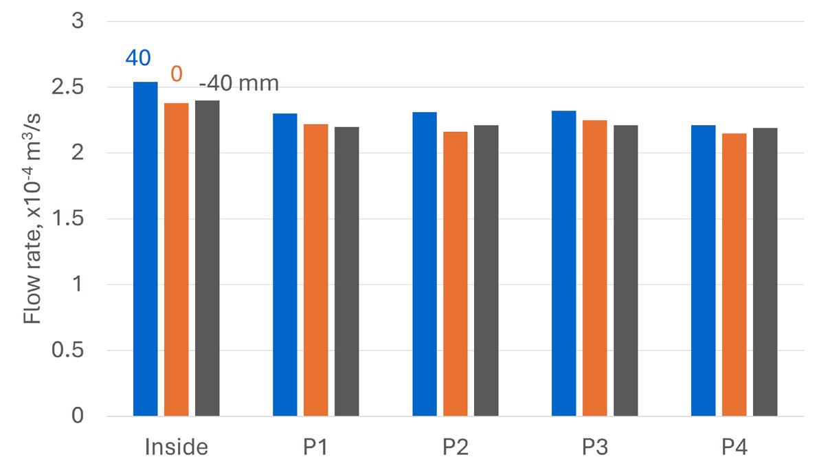
Notes
1. OPENFOAM® is a trademark of OpenCFD Ltd.
2. The other authors of this article are Farah Alattal, Gareth Hatton, Andrew York, Adrian Lawrence, and Lucy Barrass.


Alain Hermans, Rockwell
Belgium, considers how automation solutions can help the LNG industry optimise operations and efficiency.
NG represents one of the energy sectors fastest growing opportunities, both for producers and the energy transition effort. LNG is an efficient way to transport fuel from producer to consumer, helping the world meet its ever-increasing demand for energy. Emitting about 50% less carbon dioxide (CO2) than coal, LNG is often considered a ‘bridge fuel’ that can help reduce carbon emissions while the world shifts from high-emission fossil fuels like coal to renewable energy sources. But while LNG offers substantial rewards, it also poses significant challenges: tough environmental and safety regulations mandate constant vigilance; volatile markets demand agile responses; and dynamic business conditions require operational excellence.
While increased investments in LNG projects are expected, the ongoing geopolitical landscape is likely to
impact previously secure gas supplies to Europe, making LNG a crucial flexible supply source. In Asia, countries such as China and India are seeing substantial growth in LNG demand as they transition to cleaner energy sources. Regulatory developments, particularly in the EU, are focused on reducing methane emissions and addressing other environmental concerns, shaping the industry’s future. With several new LNG projects worldwide reaching key milestones, such as securing regulatory approvals or commencing production, these trends underscore the dynamic nature of the LNG industry and its vital role in the global energy landscape.
Rockwell Automation understands the problems and challenges faced by the LNG industry. Its proven process automation solutions are helping producers and LNG stakeholders around the world to enhance capital efficiency, optimise supply chains, develop downstream market infrastructure such as regasification terminals and pipelines, and adhere to evolving regulation connected with decarbonisation requirements and the wider energy transition. With offices and personnel in more than 80 countries, and maintained alliances with a strong network of global partners, the company can offer product availability and local support wherever it is needed.
The multi-faceted application of data-backed solutions for the LNG industry help producers manage demand dynamics and maintain a competitive edge, whilst contributing to a healthy bottom line. Knowing that multiple technologies and devices are required to operate a plant is why the company’s solutions integrate process and motor control, as well as safety and information technologies. The Rockwell Automation range of products and services help assure producers and terminal operators of excellent reliability and efficient terminal operation – from plant level devices to supervisory control and terminal management systems.
A typical LNG facility consists of multiple process units that are fabricated modularly and then integrated into a fully functional plant. Many of these packages (compressors, chillers, turbo-expanders, pumps, and storage tanks) will require specific controllers optimised for the type of function they will perform. For example, specific functions in a plant with high speed, discrete logic might be controlled using dedicated

programmable logic controllers (PLCs). A central control system or DCS would traditionally be commissioned in a supervisory mode to control all operations in the facility, as well as the main process area. Integration of the DCS with the skid packages used in the balance of plant is often costly and engineering intensive. Maintaining multiple disparate automation systems can strain operations and support resources, restricting flexibility and responsiveness.
The Rockwell Automation PlantPAx system provides an unparalleled level of versatility, from discrete high-speed control, to complex process algorithms and motor control in one platform. It delivers all of the core capabilities of a DCS to address the requirements of process control and is built on a technology-unified platform that easily integrates with other automation systems and critical business systems.
PlantPAx has the capability to manage points and control loops commonly found in LNG facilities, and can provide benefits, including:
z Unrestricted access to all plant assets, enables site-wide control and optimisation resulting in a lower total cost of ownership.
z System scalability and modularity for engineering flexibility.
z Connectivity for improved safety and efficient operation of plants.
z Open and information-enabled, which allows operational improvements and integration with enterprise-level reporting tools.
Leonardo, an Italian company, deployed Rockwell Automation’s PlantPAx DCS on two LNG tankers, the LNG Portovenere and LNG Lerici. This provided a modern supervisory and control system that integrated all existing on-board control systems. These tankers, built in 1997, underwent a significant renovation to extend their lifespan by 15 years. The modernisation included updating the control systems, boilers, pumps, and turbines. The new PlantPAx DCS improved command execution speed, data acquisition, and energy efficiency, providing a modern and intuitive operator interface.
Alongside Rockwell Automation’s PlantPAx DCS, the solution included high-end programmable automation controllers, standalone operator workstations, remote acquisition units, and an emergency shutdown system. As a result, the speed of command execution improved due to enhanced data acquisition and exchange speed between the controllers and I/O modules. The operator interface became modern, intuitive, and easy to use, with faster graphical recall and refresh speeds. Additionally, operating costs were reduced significantly through energy savings.
The company’s intelligent motor control offering assists with optimising the performance and reliability of control systems. It has combined its leading-edge motor control and protecting devices with the advanced networking and diagnostic technologies of the Rockwell Automation Integrated Architecture® to provide intelligent motor control.
In LNG terminal facilities, as well as ship board automation, it is critical that operators of the system have access to information
regarding critical motor status and health. Intelligent motor control technologies monitor numerous aspects of motor operations, be it a remote across-the-line starter, or a complete motor control centre. This vital data is served to the integrated architecture via proven ethernet/IP networking. The Rockwell Automation information system turns the data into actionable information, assisting LNG facility operators in keeping their systems performing at peak efficiency.
The company’s intelligent motor control technologies are integrated into its complete line of low and medium-voltage solutions and has engineered industry-leading communication and protection technologies into the broad portfolio of motor control products, including across-the-line starters, soft starters, variable frequency drives, motor control centres, and custom-packaged motor control enclosures.
The measurement of hydrocarbons, whether a gas, oil, or LNG, happens for two distinct reasons. The first is a change of ownership or custody transfer point, as it is often referred to. The second is called a fiscal measurement point, where a financial transaction such as tax or royalty is due. Both these points demand integrity and accuracy of measurement.
Sensia, a JV created by Rockwell Automation and Schlumberger in October 2019, has a team of knowledgeable engineers and project managers who understand the need for efficient and safe operations across storage, transportation, measurement, and custody transfer. Sensia has been working to qualify an LNG in-line measurement system. This is the first use of in-line meters for
fiscal allocation of LNG rundown. It may function as the first step toward using check meters for loading and offloading LNG and may have the potential for the replacement of ship measurements for LNG custody transfer in the future.
By taking advantage of easy-to-use tools and modern technology, they design solutions that help you meet plant production goals. Sensia has helped global customers seamlessly migrate their less effective control systems, update safety systems, and optimise processes by using advanced process control solutions.
Sensia also provides various engineering services that can help reduce risk while helping keep projects on time and on budget. It’s integrated information, control, and power solutions for the LNG industries are suitable for fire and gas systems, motor control solutions, metering and measurement, high integrity pressure protection systems, and pump, compressor, and turbomachinery control and condition monitoring.
Rockwell Automation supplements these technical capabilities with value-added services and expertise. The company’s people and extensive PartnerNetworkTM have expertise in the automation and control industry. While the challenges are often complex, the ultimate goal is likely a simple one: to run a profitable, safe, and sustainable operation. Having a partner with knowledge on the industry and process can help make that goal easier, perhaps through in-house experience or PartnerNetwork resources to deliver repeatable, scalable, and maintainable solutions – tailored to each case and the specific challenges being faced every day.
Brazil’s LNG imports during the 2024 drought were limited by increased wind and solar generation capacity
Brazil’s name is derived from the Brazilwood tree (Pau-Brasil), which was once a major export
Brazil currently has eight import terminals online, with another one terminal under construction
Brazil's drought in 2021 led to a record 7 million t of imported LNG for the year
Brazil is the largest country in South America
Brazil has more than 4000 airports
The Amazon Rainforest produces 20% of the world’s oxygen
Brazil’s import capacity has been increased since 2021 from 23 million tpy to over 45 million tpy
Once the Rota-3 pipeline is fully online, it can deliver roughly 625 million ft3/d of associated gas
On average, Brazil imports around 2 million tpy of LNG
Brazil is the world’s largest exporter of coffee
Brazil has won the FIFA World Cup five times, more than any other nation
Brazil borders every South American country except Chile and Ecuador
Brazil has four time zones
Since 2021, four new regasification terminals have been built


In this episode, Elizabeth Corner speaks to Kevin O’Donnell, Executive Director of the PLCAC, about how membership organisations benefit the pipeline sector and those who work in it, discussing events, networking, resources, training, skills development, and learning.
This episode of the podcast covers:
• The PLCAC’s primary aims as an association.
• The part community plays in fostering business connections.
• How to define success as a membership organisation.
• How events are evolving to meet the needs of pipeliners.
• How the PLCAC uses data from its members to advance the industry.
• And more!


From preventative VRU or VCU maintenance to system upgrades and retrofits or emergency rentals, trust our team to help keep your facility operating at peak efficiency. Zeeco Global Field Services (GFS) includes preventive maintenance and inspection (PMI), installation and commissioning, equipment turnarounds, troubleshooting, carbon testing and replacement, rental units, overnight parts supply, emergency services, emissions testing, and 24-hour repair.
Engineers and support specialists stationed worldwide