10 minute read
Dealing with rejection


Christopher Ott, Justin Bukowski, Russell Shnitser, and Jerry Dunn, Air Products, USA, explain the steps to select the best nitrogen removal for an LNG plant.
As the LNG industry continues to grow, new natural gas liquefaction projects require efficient, low CAPEX nitrogen removal options. Conventional methods of rejecting nitrogen from the LNG product to the fuel system are well known in the natural gas industry but many modern LNG plants require more sophisticated nitrogen removal and rejection methods due to one or more of the following: 1,2,3 � High nitrogen content in the feed gas. � Reduced tolerance for nitrogen content in the gas turbine fuel.
� Reduced fuel demand due to higher gas turbine fuel efficiency. � Electric motor driven plants that utilise electricity from the grid and do not have fuel requirements. � Lower allowable methane emissions from vented nitrogen.
Nitrogen is a naturally occurring, inert gas component present in natural gas. The nitrogen content of natural gas typically ranges from 0 - 5 mol.%, but some gas fields may have nitrogen content in excess of 20 mol.%. Natural gas pipelines have nitrogen specifications generally in the range of 1 - 3 mol.%. High nitrogen content in natural gas may require its removal during the LNG liquefaction process to meet LNG product specifications and to ensure safe storage. Typically, nitrogen content in LNG is maintained below
1 mol.% to prevent tank rollover (which can lead to LNG storage tank failure) and to maximise the heating value of the transported LNG.
Nitrogen is commonly removed in a simple end flash step where high-pressure LNG from the liquefaction unit is reduced in pressure to generate vapour. This vapour from the end flash drum is often referred to as flash gas. The flash gas contains a higher concentration of nitrogen compared to the feed gas allowing for efficient removal of the nitrogen from the process.
This flash gas is typically warmed before being compressed and used as gas turbine fuel for the liquefaction process. The warm stream used to recover refrigeration from the flash gas may be additional natural gas feed or another stream that maximises the heat recovery of the end flash, such as a refrigerant stream.
The amount of flash gas generated depends primarily on the temperature of the high-pressure LNG from the liquefaction unit, and to a lesser extent, on the pressure of the end flash unit. The pressure of the end flash unit is lower than the liquefaction unit feed pressure and higher than the minimum set by the end flash compressor requirements. Adjusting the temperature of the high-pressure LNG from the liquefaction unit controls how much flash gas is produced and the resulting concentration of nitrogen in the flash gas. This is important when the flash is used for gas turbine fuel. Table 1 shows the effect of changing the LNG temperature from the liquefaction unit.
Typically, there is a limit of 1 mol.% nitrogen in the LNG product and also a limit of nitrogen in the fuel gas. A good rule of thumb is that the simple end flash unit can reduce the nitrogen content of the LNG by approximately a factor of two, so a simple end flash unit is typically adequate to remove enough nitrogen from the LNG when the feed gas contains nitrogen below approximately 2 mol.%. Therefore, feeds containing high nitrogen require removal technologies beyond a simple flash drum. This article reviews solutions for removing nitrogen from the process to meet LNG storage specifications and gas turbine fuel requirements. Solutions for plants with little or no fuel requirements (for example, a motor driven plant that utilises electricity from the grid) are also discussed.
Table 1. Effect of changing the LNG temperature
LNG temperature
Warmer Colder
Flash gas flowrate More Less
% N2 in flash gas Less More
% N2 in LNG Less More

Figure 1. Nitrogen stripping column.
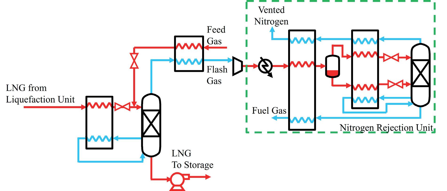
Figure 2. Nitrogen stripping column with a standalone nitrogen rejection unit.
Nitrogen stripping column
There are two common methods for removing nitrogen from LNG by generating flash gas. The most common option is the simple end flash unit previously discussed. Another common equipment arrangement replaces the end flash drum with a distillation column that strips nitrogen from the LNG. As shown in Figure 1, this unit utilises high-pressure LNG to provide boil-up in the bottom of the column to reject a larger percentage of the nitrogen from the LNG than can be achieved in a single flash. While this allows efficient removal of nitrogen from the LNG, without generating large amounts of flash gas, the consequence is that the nitrogen is concentrated in the flash gas which impacts the fuel quality for the gas turbines.
The two options described above are suitable for many LNG applications, however these options may not be feasible for high nitrogen content feed gas (for example, greater than 4 mol.% to 5 mol.% nitrogen), drivers that require low nitrogen content fuel (for example, less than 20 mol.% nitrogen), or for plants with low fuel requirements (for example, a motor driven plant that utilises electricity from the grid).
Nitrogen rejected in standalone unit
One solution is to further process the resulting flash gas in a standalone nitrogen rejection unit (NRU). One example of a standalone NRU is illustrated in Figure 2. An NRU produces a nitrogen stream and a nitrogen depleted gas stream containing as little as 1 mol.% nitrogen. The nitrogen depleted gas stream from the NRU can then be used to fuel the gas turbines or can be recycled to the LNG plant feed gas in the case of a plant that does not require fuel.1 The NRU can be designed to produce a high purity nitrogen stream containing ppm levels of methane that can be vented to the atmosphere or used as a nitrogen product. A standalone NRU is more CAPEX intensive compared to the simple end flash unit or nitrogen stripping column due to the additional equipment necessary for this process. This can include additional compressors, distillation columns, separators, and heat exchangers. The non-rotating equipment is commonly combined in a cold box due to cryogenic operating temperatures.
Nitrogen management for low fuel requirements
An LNG plant that has minor fuel requirements, such as process heating or flare header purge, can employ a scheme
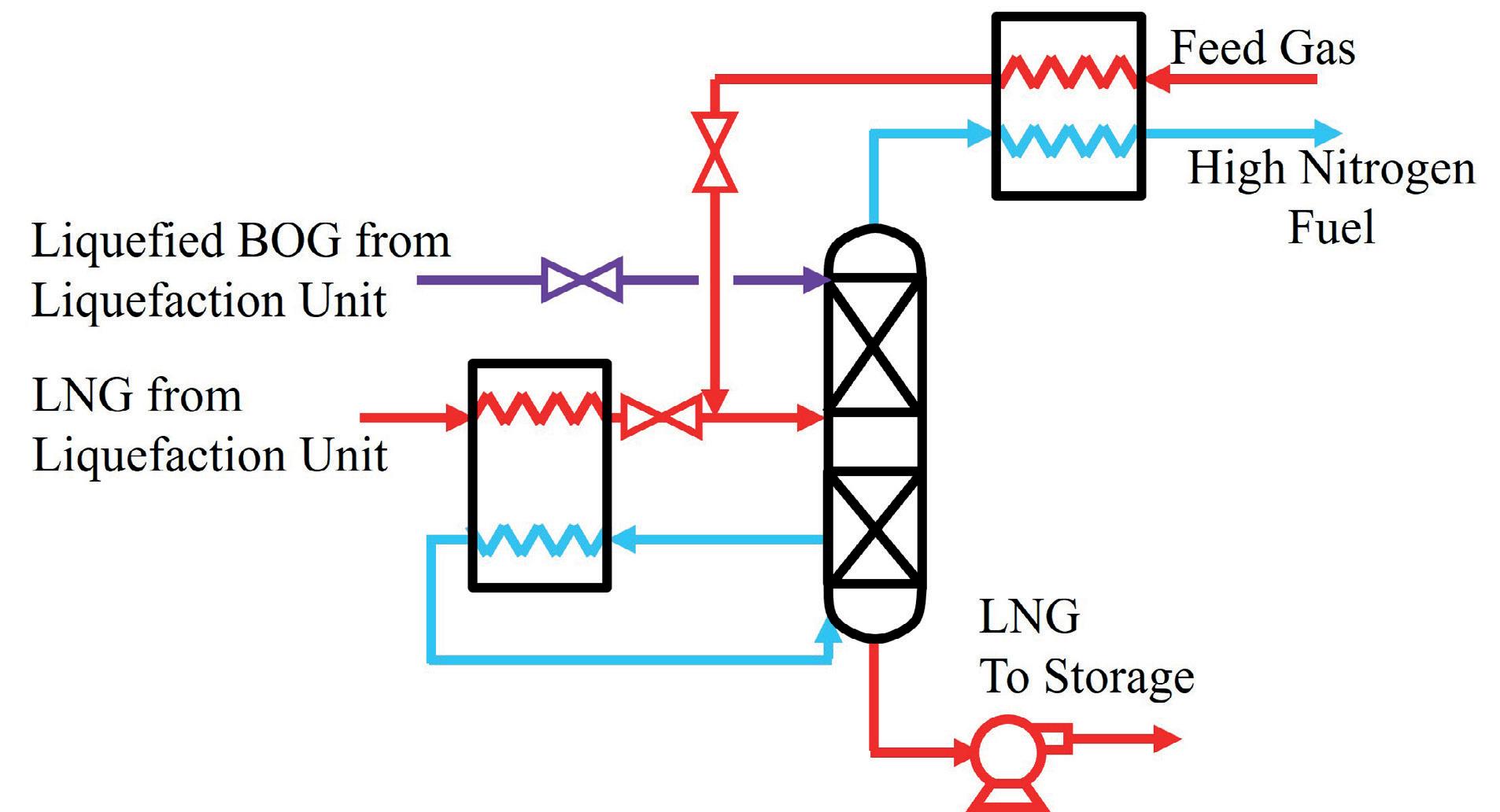
Figure 3. Integrated nitrogen rejection unit with boil-off gas (BOG) reflux.
Figure 4. Integrated nitrogen rejection unit with fuel.
Table 2. Summary of equipment arrangements


Figure 5. Integrated nitrogen rejection unit with N2 reflux. shown in Figure 3. This arrangement uses a rectification column with reflux provided by a slip stream of recycled boiloff gas (BOG) from the LNG storage tank which is compressed, liquefied in the liquefaction unit, and let down in pressure.4 The nitrogen purity of the overhead stream is limited by the composition of BOG which refluxes the column. The methane content in the overhead stream will typically be too low for gas turbine fuel and too high for venting to the atmosphere. The overhead stream can be used in a system such as a boiler or fired heater that accepts low heating value fuels, for example, the AGRU reboiler or dehydration unit regeneration heater.
Integrating the nitrogen rejection equipment with the existing LNG liquefaction process reduces equipment count and may be preferred over the standalone option covered in Figure 2. This is accomplished by taking advantage of the existing cold LNG temperatures and liquefaction refrigeration system. One such option is shown in Figure 4. This is a patent pending option that is well suited for an aeroderivative gas turbine driven LNG plant with tight limitations on the fuel nitrogen content. This arrangement produces a high purity nitrogen vent or product, a fuel stream that meets tight fuel quality specifications, as well as an LNG product with less than 1 mol.% nitrogen for a wide range of nitrogen concentrations in the feed gas.
This arrangement uses the nitrogen stripper of Figure 1 and adds a rectification column to produce a fuel stream and a high purity nitrogen stream. A bypass line, shown by a dashed line, controls the fuel quality and minimises the size of the nitrogen rejection equipment. The rectification portion of the process operates as a total condenser and uses a nitrogen recycle loop to provide reflux to the column. Low nitrogen fuel is the liquid product from the rectification column and is vaporised to provide refrigeration for the nitrogen reflux stream, eliminating the need for supplemental refrigeration. If the nitrogen content in the feed gas is reduced, the nitrogen vent will close to maintain pressure in the system. If the nitrogen content in the feed gas falls below 1 mol.%, which is below the typical nitrogen concentration target for LNG, the nitrogen vent will fully close and the rectification column will operate in total reflux, ready to
Description Simple end flash unit N2 stripping column N2 stripping column with NRU Integrated NRU with BOG reflux Integrated NRU with fuel Integrated NRU with N2 reflux
Figure number Figure 1 Figure 2 Figure 3 Figure 4 Figure 5
Fuel produced High Medium Medium Low Medium None
Nitrogen content in fuel Low High Low Highest Low No fuel produced
Equipment count Lowest Medium Highest Medium High High
Nitrogen vent No No Yes No Yes Yes
resume operation when the nitrogen content in the feed increases.
Nitrogen management for no fuel requirements
Figure 5 shows another patented, integrated option that produces a pure nitrogen stream.5 This option is well suited for an LNG plant that has little or no fuel requirements such as a motor driven plant that utilises electricity from the grid. This arrangement accommodates a wide range of feed gas nitrogen concentrations by producing high purity nitrogen that can be vented to the atmosphere or used as a nitrogen product as well as producing LNG with less than 1 mol.% nitrogen. The existing refrigeration infrastructure for the LNG plant is leveraged by providing a slip stream of refrigerant to supplement the compressor driven Joule-Thomson (J-T) refrigeration in the nitrogen rejection unit. In this example, the LNG plant is assumed to be using a mixed refrigerant cycle and the supplemental refrigeration is provided by the mixed refrigerant from the main cryogenic heat exchanger (MCHE). The process can be adapted to use refrigeration from other liquefaction cycles as well.
This arrangement is also very flexible with variability in the feed gas nitrogen content as the rectification portion of the process operates as a total condenser. If the nitrogen content in the feed gas is reduced, the nitrogen vent will close to maintain the pressure in the system. If the nitrogen content in the feed gas falls below 1 mol.%, which is below the typical nitrogen concentration target for the LNG, the nitrogen vent will fully close and the top of the column will operate in total reflux, ready to resume rectification when the nitrogen content in the feed increases.
Conclusion
New natural gas liquefaction projects require efficient, low CAPEX nitrogen removal options. Several practical options for nitrogen removal from LNG have been described in this article and each arrangement offers unique benefits. There is no single solution that can be applied universally as each project will have different requirements. Key project variables such feed gas composition and the selected refrigerant compressor driver impact the suitability of each nitrogen rejection solution. It is critical to understand the benefits of different equipment arrangements to develop a robust and reliable project selection.
References
1. OTT, C.M., ROBERTS, M.J., TRAUTMANN, S.R., and
KRISHNAMURTHY, G., ‘State-Of-The-Art Nitrogen Removal for
Natural Gas Liquefaction’, Gastech, March 2014. 2. SAUNDERSON, R.P., ‘End-Flash Is Totally Cool’, Hydrocarbon
Engineering, May 2021. 3. BERG, J., SCHMIDT, W., CHEN, F., and OTT, C., ‘Designing
Flexible Plants for Market Adaptation’, LNG Conference, April 2019. 4. CHEN, F., LIU, Y., KRISHNAMURTHY, G., OTT. C.M., and
ROBERTS, M.J., ‘Integrated Nitrogen Removal in the Production of Liquefied Natural Gas Using Intermediate Feed Gas
Separation’, US10767922, 8 September 2020. 5. OTT. C.M., KRISHNAMURTHY, G., CHEN, F., LIU, Y., and
ROBERTS, M.J., ‘Integrated Nitrogen Removal in the Production of Liquefied Natural Gas Using Refrigerated Heat Pump’,
US9945604, 17 April 2018.
TO UP YOUR LNG GAME YOU NEED VALUE-DRIVEN INNOVATION. REGO® BRINGS IT.

RegO innovation delivers full solutions for truck cylinders, dispensers, bulk storage and transport applications that increase performance, service life, ease-of-use — and lower your cost of ownership.
REGO 100% TESTED
PRODUCT
GODDARD® GATE VALVES See the complete line at regoproducts.com/lng +1 336.449.7707