10 minute read
The art of detection


Kevin Dean, MSA Safety, UK, describes how to improve the probability of detecting LNG leaks, by using laser open path gas detectors.
Open path gas detectors (OPGD) utilising non-dispersive infrared (NDIR) sensor technology have been in use since the late 1980s and are widely accepted by many oil and gas (including LNG operations), petrochemical, and other high-risk industries as supplementary protection for the detection of hydrocarbon combustible gases. OPGDs improve the probability of detecting gas leaks that point gas detectors on their own may not detect or not as quickly as expected. As the gas cloud must migrate to the point detector and specifically to the ‘point’ inside the device where the sensor is located, strong winds can be one of the reasons for gas leaks going undetected. With OPGDs, the gas cloud still has to migrate to the beam that is transmitted from the transmitter (source) to the receiver. However, as the beam of the OPGD can be very long (up to and in excess of 100 m – application dependent) the probability of detection is increased. This is because the gas will be detected anywhere along the entire length of the beam and not just within the small sensor housing of the point gas detector. NDIR-based OPGD systems are commonly used to monitor hydrocarbon gas leaks on offshore and onshore oil and gas production facilities, LNG facilities, refineries, gas transmission stations, and many other high-risk industrial facilities.
These devices respond to the presence of any hydrocarbon gas leak that reaches the beam of an NDIR OPGD. Each system is supplied calibrated to read accurately for one specific target gas but will also detect other hydrocarbon gases. However, only the target gas to which it is calibrated will be detected at the correct measurement value.
The measuring range is expressed in Lower Flammable Limit.metres (LFL.m), which is the gas concentration within the beam, multiplied by the length in metres of the gas cloud in the beam.
These devices are ideal for detecting high concentration/small gas clouds and low concentration/ large gas clouds, as they migrate from the point of release across a site (Figure 1).
Since the introduction of NDIR-based OPGD for hydrocarbon gases, end users have requested additional capabilities for OPGD, these included: � Increased sensitivity, i.e. the ability to detect lower concentrations of escaping gas. � Target gas specific detection, i.e. methane specific with no cross sensitivity to any other hydrocarbon gases. � Increased uptime availability in adverse/severe weather conditions, i.e. in climates subject to heavy rain and fog.

� Auto self-testing to avoid routine manual testing with optical filters, requiring maintenance engineers to go into the hazardous area – both time consuming and increasing the risk for the engineer.
These additional requirements are beyond the capabilities of traditional NDIR OPGD systems and led to the design and development of laser-based OPGD systems.
MSA-Senscient launched its range of laser-based OPGDs in 2009 using a technique called enhanced laser diode spectroscopy (ELDS™). Laser-based OPGDs: � Are target gas specific, and available for: methane, ethylene, hydrogen sulfide, hydrogen fluoride, hydrogen chloride, carbon dioxide ammonia, or sour gas (hydrogen sulfide entrained within methane). � Offer three orders of magnitude in increased sensitivity for methane, greatly increasing the probability of detecting a methane gas leak before it reaches catastrophic proportions. � Include the unique SimuGas™ self-test facility that enables automatic or on demand functional testing of open path gas detectors locally.
The ELDS technology utilises highly reliable, solid-state laser diode sources, similar to those used in demanding telecommunications applications.
Innovative signal processing methods significantly increase sensitivity, enabling reliable detection to much lower LFL.m values of combustible gases than NDIR OPGDs and even lower ppm.metre levels of toxic gases.
The ELDS technology addresses problems experienced by traditional laser diode systems including laser relative intensity noise (RIN), absorption by atmospheric gases, and coherence/ fringe effects, which can result in false positives and unwanted plant shutdowns.
The ELDS technology also uses a combination of techniques which significantly enhance the ability of an OPGD to detect small fractional absorbances with an extremely low false alarm rate.
For LNG applications, the methane ELDS OPGD is designed to be an ideal solution to increase the probability of the early detection of gas leaks and can cover up to 200 m (application dependent) with one system. It also has the option of detecting very low concentrations of gas clouds in the range of 0 - 1000 ppm.m, medium concentrations 0 - 1 LFL.m, or high concentrations 0 - 5 LFL.m. Being able to detect very low concentrations of gas can help give the earliest possible warning of an LNG gas leak.

Figure 1. Gas cloud concentrations and OPGD gas readings.
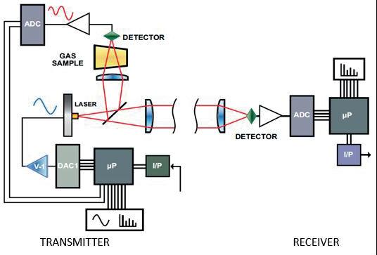
Figure 2. ELDS system schematic.
Principle of operation
Using a separate transmitter/receiver configuration, ELDS systems detect and measure gas concentrations at specific target gas absorption wavelengths over distances of up to 200 m (gas and measuring range dependent).
Transmitter
The transmitter assembly comprises of a hazardous area certified enclosure that houses the laser, collimating optics, a gas reference cell filled with a sample of the target gas and electronics (Figure 2).
The laser diode is driven by a current and generates infrared radiation at a known absorption wavelength of the target gas. The laser is then scanned across this absorption wavelength for a designated time interval.
Every ELDS transmitter contains a hermetically sealed gas reference cell filled with a sample of the detector’s target gas, which is monitored by a dedicated photodiode to ensure the laser remains locked on the absorption wavelength. This ensures the system will respond to the target gas and removes any possibility of an unrevealed failure often associated with devices that do not use a gas reference cell filled with the target gas.
Receiver
The receiver analyses the incoming signal using the well proven technique known as Fourier transform. Fourier transform is commonly used within laser-based process gas analysers and converts the incoming signal from the time domain into a frequency domain.
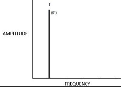
When viewed in the frequency domain, the incoming signal is presented as a single harmonic frequency (f) when no gas is present (Figure 3), or a number of harmonic frequencies (f2, f3, f4, f5) when the target gas is present in the path of the laser.
The inter-relationship/pattern and phases of these harmonics (f2, f3, f4, f5) for a specific gas are unique to that gas and represents its harmonic fingerprint. A harmonic fingerprint that does not match that of the target gas, which may have resulted from an interferent gas or environmental conditions, is rejected and no alarm is raised.
Harmonic fingerprint analysis, using multiple harmonics (f2, f3, f4, f5) ensures the device only responds to the target gas, eliminating false alarms associated to devices that only look for the presence of one harmonic (f2).
The amplitude of the harmonics is proportional to gas concentration. Gas concentration is then reported via the proportional, analogue (mA) output to an associated control system to initiate executive action.
Uptime availability
A traditional NDIR OPGD operates at wavelengths in the region of 2.2 - 2.3 µm or 3.0 - 3.3 µm. While both IR wavelength ranges are suitable for detecting hydrocarbon gases, both ranges are
prone to a significant loss of signal at the receiver when the detection path contains steam, rain, or fog. This loss of signal is a result of water vapour absorbing the IR radiation and the longer the path length (distance between the transmitter and receiver), the greater the absorption and the more often the OPGD will go into beam-block. This is a serious fault condition, as when the unit has a beam-block fault, the OPGD is unable to detect gas. During heavy fog or rain, multiple NDIR-based OPGDs may not be able to detect potential gas leaks.
ELDS systems operate in the region of 1.6 µm where the loss of signal due to steam, rain, and fog are significantly less. It is for this reason that laser-based OPGD is being used as the preferred method of detection in these environments.
However, it should be noted that while laser-based OPGDs uptime availability will outperform NDIR OPGD, it still has its limits. These limits can be extended by shortening the path length between the transmitter and receiver. Proof testing A traditional NDIR OPGD can be proof tested by the use of a gassing cell that is manually fixed to the receiver. The gassing cell is a tube with optical windows at each end that can be filled with a known concentration of test gas.
An easier alternative is to use optical filters. These are thin plastic film discs that are inserted at the receiver of various thicknesses. As NDIR OPGD devices are not target gas specific, they respond to these plastic (hydrocarbon) filters. The different thicknesses of the test filters generate a different reading at the receiver.
Laser-based OPGDs are target gas specific and therefore will not respond to plastic (hydrocarbon) filters. For laser-based systems it is possible to use a gassing cell arrangement for target gases that are environmentally stable, e.g. methane, ethylene, hydrogen sulfide, and carbon dioxide.
An alternative for all detectable target gases within the Senscient OPGD range is the use of the SimuGas test facility. Test facility The SimuGas facility is a simple and highly reliable functional test for the OPGD. In an ELDS system with SimuGas, testing the transmitter’s microprocessor has direct control of the synthesis of the laser diode drive waveforms, as well as access to the harmonic fingerprints being produced by the absorption of laser diode radiation by the retained sample of target gas.
Upon receiving an automatic command instruction or a manual one from an operator or the control system, the transmitter’s microprocessor adds harmonic fingerprint components to the laser diode drive waveforms, to simulate the
presence of a given quantity of target gas in the monitored space. The optical radiation leaving the transmitter then faithfully simulates the presence of target gas in the monitored path. When the receiver processes the signal that it is receiving from the transmitter, it sees the harmonic fingerprint components and calculates the corresponding quantity of target gas. Figure 3. Left: Fourier transform of zero gas signal for Interval T. Right: Fourier transform of positive gas signal for Interval T. By simply comparing the gas reading output by the receiver to the quantity of target gas that the transmitter was instructed to simulate, it is possible to verify the correct operation of the gas detector. To avoid unwanted activation of executive actions during a SimuGas test, the analogue (mA) output of the receiver is held at the value immediately prior to the SimuGas test for the duration of the test. SimuGas gas testing of all ELDS systems is performed automatically every 24 hours but can also be initiated on demand at any time. The SimuGas test results are held within an onboard event log and can be retrieved for future reference. Any test failures will generate a fault output. The SimuGas facility testing has the following advantages: � Functional testing can be performed remotely, without operators needing to gain access to difficult-to-reach gas detectors. No more scaffolding or abseiling. � Gas detectors can be functionally tested much more frequently, providing greater safety integrity. � There is no need to carry cylinders of hazardous gases around facilities in order to test gas detectors. � The results of detector functionality testing can be logged and retrieved automatically. � The operation and maintenance costs for the OPGD are greatly reduced. Applications Similar to traditional NDIR-based OPGDs. A laser-based OPGD is used for monitoring: plant perimetres, pipelines, process area boundaries, process pipe racks, process pump rows, storage tanks, air intakes, road/rail loading areas, loading jetties, etc. Conclusion A laser-based OPGD is an effective gas detection technology that complements and/or addresses limitations of other gas detection technologies providing: � Greater probability of detecting LNG gas releases than point detectors on their own. � Reliable gas detection of only the specific target gas. � Increased detection sensitivity. � Faster speeds of response as it is capable of detecting lower gas concentrations. � Reduction of false alarms, as other substances/gases cannot be detected. � Less downtime/loss of detection in heavy fog or rain. � Reduced routine maintenance costs. � Reduction in the frequency of personnel visiting the hazardous area.