8 minute read
Up to the challenge


David Walsh, Howden, Scotland, introduces a method for controlling the main air blowers within the sulfur recovery process, which will help to improve energy efficiency.


Today, the global oil, gas and petrochemical industries face challenges like no other time in the past. How does one extract and process oil and gas resources in a safe, environmentally friendly, and effi cient way whilst also reducing costs? Whilst the challenge is new, the answer is not. It lies in harnessing the collective knowledge and expertise across the complete value chain, working together towards the necessary solutions.
This article will demonstrate a method for controlling the main air blower within the sulfur recovery process that will improve the overall system energy effi ciency and reduce both CAPEX and OPEX. The article will also attempt to make a valuable contribution to the overall challenges faced by the industry today and in the future.
The sulfur recovery unit (SRU) is an important part of the refi ning process. The Claus process is the most commonly used to remove hydrogen sulfi de (H2S) from the raw natural gas and crude oil.
The wide scale proliferation of the sulfur recovery process was largely driven by European standards for vehicle exhaust emissions starting in 1992, and the legal requirements for the removal of sulfur from fuels have become ever more stringent over the years. With EURO 7 expected later in 2021, and likely to come into force in 2025, the pressure is on refi ners to remove

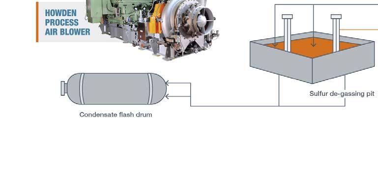
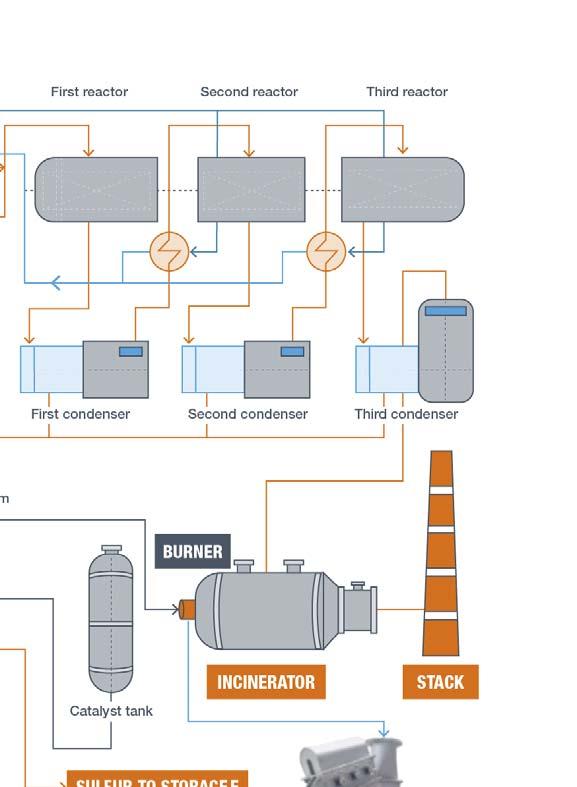
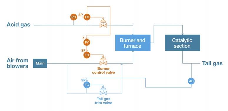
Figure 1. Reviewing a typical SRU process provides more of an insight into the control philosophy of the sulfur recovery reaction.

ever more sulfur and other chemicals harmful to our environment from their fi nal products. This is especially the case now as the available crude oil and gas reserves are ever more sour. That the sulfur is removed is not just important from a legislative and quality perspective, but also from the perspective of the environment and the health and well-being of the global population.
The SRU process is generally governed by the Claus process and is widely available from a number of technology licensors around the globe. Figure 1 shows a typical process diagram where the acid gas (H2S) is burned in a reactor to form elemental sulfur.
Howden supplies main (sometimes called Claus or combustion) air blowers, which are utilised to provide the oxygen (O2) to the combustion reaction within the Claus burner. Within the process, Howden also supplies the incinerator and degassing air blowers.
It can be seen in Figure 2 that the air (more precisely the oxygen) from the main blower is fed to the burner via a control valve based on the acid gas fl ow to achieve the optimal air/gas mix for the burner. The tail gas analyser loop further adjusts the air fl ow by a separate trim valve to achieve the optimum H2S to SO2 ratio for Claus conversion, and so optimises the removal of sulfur from the tail gas.
Typically, the blower output is controlled to a pressure set point, the burner feed valve is controlled to a fl ow set point, and the trim valve is controlled to a tail gas mix set point. This ‘separate system’ approach is common in turbo blower control systems and has several drawbacks – in particular, it is not energy effi cient.
One of the most effi cient control methods that Howden successfully applies to its turbo technologies is the ‘most open valve’ (MOV) principle. This can be applied to the SRU to control the O2 levels in the Claus burner directly from the output of the turbo blower with minimum energy consumption. By controlling both the blower and the downstream valves using the MOV principle, the blower output is optimised to meet the required O2 level in the process. The MOV control loop works by maximising the valve opening (within the control range of the valve), which minimises the pressure (head) losses in the system. This reduction in the required system pressure allows the blower discharge pressure to be reduced correspondingly, with no loss of fl ow. This reduces the energy consumption and the cost of running the process. It has been demonstrated in practice that by applying these principles up to 25%, power saving over conventional header pressure control systems can be gained.
In the case of the SRU, by considering both the blower and downstream valves as an integrated system rather than as separate, independent systems, it is possible to improve the overall energy effi ciency of the system. In the SRU process, Howden blowers typically operate at several hundred kW, up to several mW in the largest SRUs, and normally run 24/7, so the wasted energy is signifi cant. In addition, the incorporation of the tail gas trim signal into this integrated system could allow the trim valve to be removed from the process, with the blower
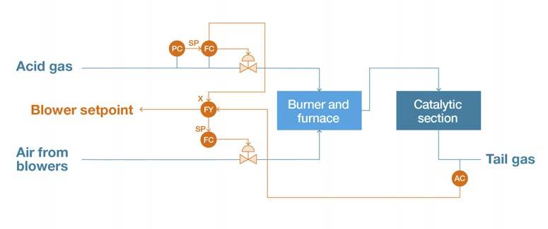
guide vanes and main fl ow control valve working together to provide effi cient fl ow regulation. This would further reduce pressure losses and introduce signifi cant CAPEX savings by removing the trim valve and its associated pipework, supports, foundations, etc. Design costs would also be lowered, which helps to reduce the cost of the blower package itself and its auxiliaries. The proposed fi nal process schematic is shown in Figure 3.
This philosophy could be applied both to new plants or retrofi tted into existing sites with signifi cant benefi ts to be gained in all cases. The output of a turbo blower is controlled by a process demand which is fed to the blower control system.
Those readers familiar with turbo technologies and with the respective American Petroleum Institute’s (API) standards API 672 and API 617 (‘Packaged Integrally Geared Centrifugal Air Compressors’ and ‘Compressors and Centrifugal and Axial Compressors’, respectively) will be familiar with the concept of inlet guide vanes for blower capacity control.
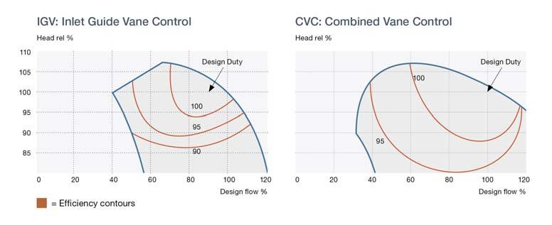
Variable speed or frequency drives are also employed; however, these are of little commercial or technical benefi t unless there is a wide variation in the pressure requirement of the blower, which is not the case in the Claus process. Howden blowers use both inlet and outlet guides vanes (combined vane control or CVC) to maximise the blower effi ciency over a wide turndown range. These guide vanes are independently controlled by linear actuators, allowing highly accurate process control across the entire operating envelope of the blower. This is the Figure 2. Considering a single blower feeding a single reactor with a burner air flow control valve and parallel trim valve. most effi cient method of controlling a turbo blower. The combined inlet and outlet vane system offers signifi cant advantages. The effect of the additional outlet guide vanes is to increase the operating envelope of the blower (increase the turndown capability) and also to increase and maintain a higher level of effi ciency during turndown, as can be seen in Figure 4. The CVC system has a wider overall envelope, and the region in which the peak effi ciency is maintained is much larger than the inlet guide vane only system. The combined vane feature is particularly important for the Claus process because the ability to turn down the blower is a requirement Figure 3. Process diagram showing the Most Open Valve1 (MOV) of the process itself and depends on the load on the principle. refi nery and the quality of the feedstock at any given time. The more the blower can turn down, the less likely it is that there will be a need to blow-off excess air, which is a highly ineffi cient process. The more effi ciently the blower operates during turndown, the less energy is wasted. Since the Claus process utilises atmospheric air, which has constantly changing properties (e.g. from day to night or from summer to winter), the temperature (and therefore density) variation can be relatively large. Variation in the air density causes the volume of air required by the Claus process to vary even when the process itself has a constant demand Figure 4. Inlet Guide Vane Control (IGV) and Combined Vane (i.e. the process is only interested in the mass of Control (CV) operating envelopes. oxygen to assist the burning of the sulfur). However, the resultant variation in capacity requirement of the blower is handled automatically by Howden’s combined inlet and outlet guide vane and blower control systems working in tandem to provide the operator with a large, accurate and effi cient operating window. Controlling turbo blower technology directly by the process demand using the MOV principles can result in energy savings of up to 25%. In the sulfur recovery process, if both the blower and downstream control valves are operated as integrated systems rather than as separate, independent systems, the overall energy effi ciency of the system can be improved and the amount of equipment required in the system to maintain the process can be reduced. Improved effi ciency and removal of unnecessary controls and their associated systems has the combined advantage of reducing both CAPEX and OPEX, which delivers benefi t to the whole sulfur removal value chain from refi ner, licensor and EPC contractor to ultimately the end customer and our natural environment.