10 minute read
An iron will


Qianqian Liu, Zhenyu Chen, Haitao Song, Chunfang Chen, Rui Bai, Ning Li and Liqiang Liu, SINOPEC, China, explore the application of a high iron tolerant catalyst in residue FCC.

There is growing concern about iron contamination on fl uid catalytic cracking (FCC) catalysts due to the processing of opportunity crudes in the pursuit of higher profi t margins from refi neries. The Sinopec Hainan refi nery has encountered severe iron poisoning since 2016. As a result, the Sinopec Research Institute of Petroleum Processing (RIPP) has conducted extensive research on the mechanism of iron poisoning on FCC catalysts, and a recent study reveals that iron can migrate among particles.
Based on the understanding of the iron poisoning mechanism, RIPP explored the ‘catalyst with metal trap’ (CMT), which contains metal capture components and is characterised by high porosity. The CMT catalyst has been successfully applied in the residue FCC unit of the Hainan refi nery since 2017. The CMT catalyst maintains good heavy oil cracking performance and product selectivity, even when the total contaminant metal content of E-cat exceeds 20 000 ppm (~10 000 ppm Fe).
Background


Among the common contamination issues that exist during petroleum processing, vanadium (V), nickel (Ni), and iron (Fe) are the most important metal elements.1,2 Vanadium and nickel have been subject to more in-depth studies. Under hydrothermal conditions, vanadium attracts framework alumina to form aluminium vanadate, accelerating the dealumination of the zeolite phase and the destruction of zeolite framework.3 For nickel, the metallic nickel tends to relocate on the catalyst surface, forming extra active sites with dehydrogenation activity.4 In contrast, the origins of the detrimental effects of iron are still under debate. Multiple possible phase formation/transitions may occur, and different concentrations of iron can eventually have different impacts. It has generally been accepted that iron fi rstly deposits onto the catalyst surface, forming a solid shell with unknown composition. Afterwards, such a solid shell would hinder the diffusion of heavy hydrocarbon molecules.5,6,7 Further details are still required to understand the solid phase transition to further improve catalytic performance and durability.

FCCU iron poisoning in the Hainan refinery
The Hainan refi nery adopts the maximising iso-paraffi ns process for cleaner gasoline and propylene production (MIP-CGP process) developed by RIPP to produce more iso-paraffi n and propylene in its heavy oil catalytic cracking unit. The regenerator utilises an overlapping two-stage regeneration form, with partial burn in the fi rst stage and full burn in the second stage. The catalyst enters the bottom of the riser from the second stage regenerator through the regeneration inclined pipe. The unit’s feed is hydrotreated residue. Since November 2015, the Hainan refi nery began to process high iron feedstocks.
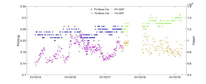
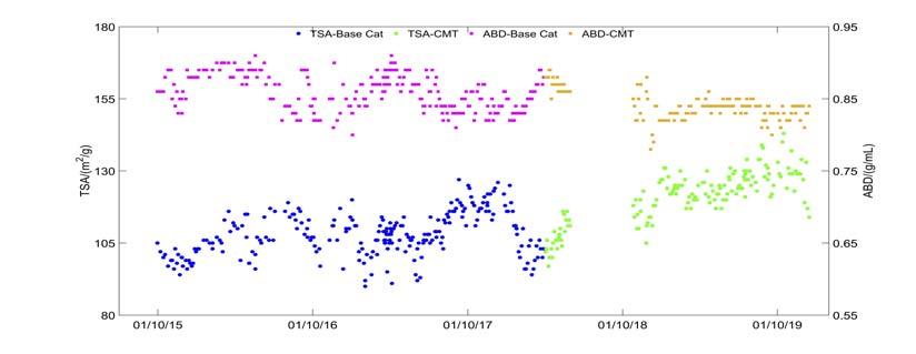
In April 2016, the unit encountered severe iron poisoning. A rise in the bed level of the second stage regenerator was observed, as well as an increase in the density of the dilute phase. These are typical iron poisoning phenomena, which are caused by the nodular surface of the iron poisoning catalyst. As the catalyst inventory of the second stage regenerator decreased continually, the operation team kept the device running by reducing the second stage regenerator air volume and fl ushing with fresh catalyst. Meanwhile, the product slates were greatly affected with a sharp increase in the slurry yield from the conventional 5% to 9% (Figure 1, top image). This indicated the decline in the conversion of heavy oil. Physical properties of E-cat during the same period (as shown in Figure 2) also refl ected serious iron poisoning. The iron content of E-cat increased from 6000 ppm to 11 000 ppm, and the pore volume of E-cat decreased from 0.25 ~ 0.26 mL/g to 0.22 ~ 0.24 mL/g, which was also caused by the nodular surface. As shown in Figure 3, the specifi c surface area of E-cat decreased from 120 m2/g to 100 m2/g, and the apparent bulk density also decreased.
Research on iron poisoning
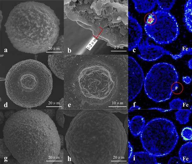
Figure 4 shows scanning eclectron microscope (SEM) pictures of high iron contaminated E-cat. As is shown, the surface of E-cat becomes notably less smooth and some nodules are formed. A 1~2 μm dense shell is formed on the intersection of the E-cat particle. Some particles with special surface texture can also be found;

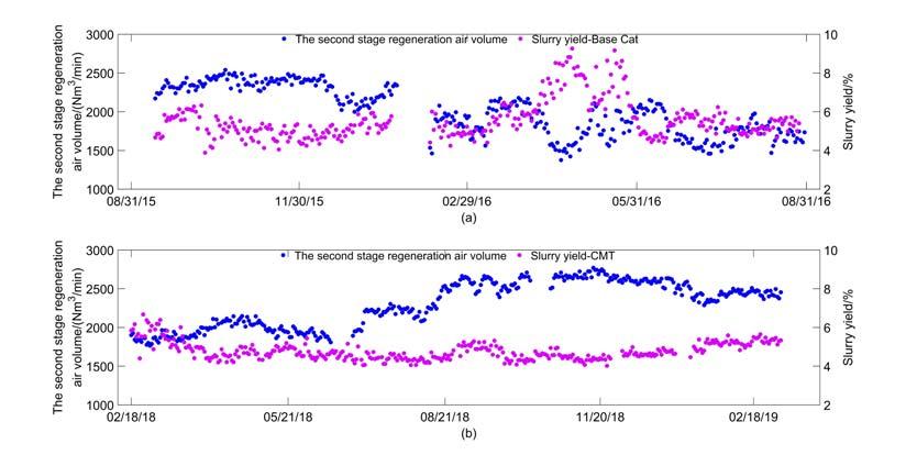
Figure 1. The second stage regeneration air volume and slurry yield vs time.
CMT design
Figure 2. Pore volume and iron content of E-cat vs time.
for example particle ‘d’, which has some signifi cant collapses resulting in many fi ne particles at the collapse sites. The elemental analysis of these fi ne particles was conducted and it was found that the iron content in these positions was much higher than others, being consistent with the iron distribution in particles ‘c’ and ‘f’. A signifi cant enrichment of iron has been observed in the position marked with the red circle. It is speculated that the mobility of iron has caused such consequences. Two possible ways of mobilisation are: Intraparticle mobility, providing the diffusion through the same catalyst particle. Interparticle mobility, leading to the element transfer between different catalyst particles.
Research has proved that vanadium is mobile under FCC conditions and distributes evenly in the catalyst, while nickel
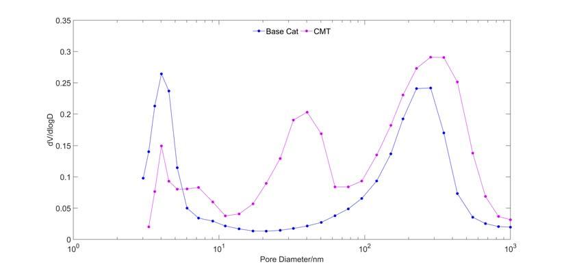
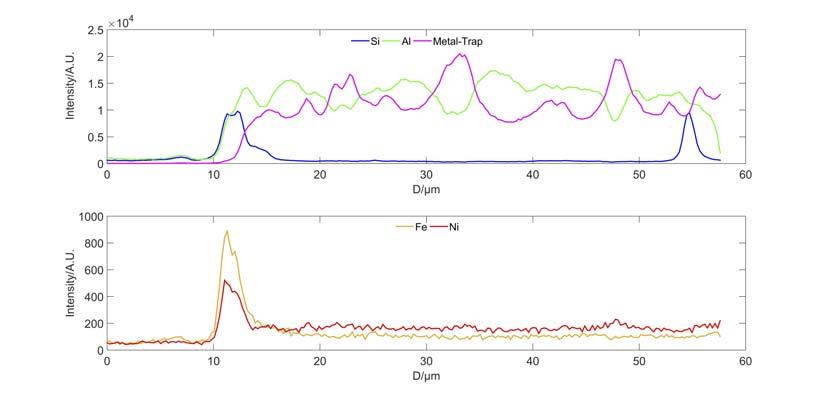
is documented to be immobile, staying at the original location. From particles ‘c’ and ‘f’ in Figure 4, it is observed that iron tends to deposit on the outer surface of the particles, which indicates that the intraparticle mobility of iron is very low. Interparticle mobility of iron was therefore studied.8 High iron E-cat and a fresh catalyst MT composed of alumina and a metal trap component (M) were mixed and then treated in a fl uidised hydrothermal ageing unit. Elemental distribution on catalyst MT was measured by electron probe micro-analysis (EPMA) line scanning after hydrothermal treatment (Figure 5). It can be clearly observed that Fe, Si and Ni are enriched on the edge of particle MT, proving that the agglomerates of Fe and Ni deposited on E-cat can form eutectic with Si and move from one particle to the other by collision. All in all, such enrichment of iron on the catalyst surface causes the surface melting and serious collapsing. CMT catalyst was then developed for cracking the heavy oil, based on the study discussed and the metal trapping technology platform which is effective on trapping and passivating contaminant metals including vanadium, nickel and iron. The metal trapping platform contains metal capture components and activated aluminium oxide matrix, which can capture iron and form a high melting point substance, thus reducing the iron migration and making it more uniformly deposited on the surface of the catalyst. More importantly, CMT catalyst has a high mesoporosity (~ 40 nm) and macroporosity (~ 283 nm) compared to traditional catalyst measured by Hg porosimetry (Figure 6). Therefore, the CMT Figure 3. Total surface area and apparent bulk density of E-cat vs time. catalyst maintains good heavy oil cracking performance and product selectivity, even with the total contaminant metal content of E-cat exceeding 20 000 ppm.
Results of industrial applications
Since July 2017, the FCCU of the Hainan refi nery began to use the anti-metal catalyst CMT provided by RIPP.9 During its normal operation, the iron content of the E-cats in the Hainan FCCU was maintained at 8000 ~ 10000 ppm (Figure 2), accompanied by the nickel content at 5000 ~ 6000 ppm and vanadium content at 4000 ~ 5000 ppm. The second stage regenerator air volume maintained stability and the slurry yield was ~ 5% (Figure 1, bottom image). Meanwhile, the pore volume of Ecats was 0.28 ~ 0.3 mL/g (Figure 2). The total surface area (TSA) was maintained > 120m2/g and the apparent bulk density was basically stable (Figure 3). Therefore, the catalyst fl uidisation remained normal. The morphology and metal distribution of the CMT catalyst are
shown in Figure 4, particles ‘g’ to ‘i’. It can be seen that the iron is more evenly dispersed on the surface of the spent catalyst (with CMT). This is due to the effective passivation of the metal trapping components and the large porosity of the catalyst. In the case of increased iron contamination, by using CMT catalyst, the gasoline and total liquid yield have been improved by 1.35 wt% and 0.39 wt%, respectively.
The CMT catalyst, with excellent heavy metal tolerance, enables heavier and inferior feedstocks to be processed, which extends the source of FCC feedstock and increases the profi t margin of FCC units. Meanwhile, the metal trapping components are environmentally friendly. CMT catalyst has been applied to another four heavy oil catalytic cracking units in China. The highest metal content of Ecat is more than 30000 ppm, of which the iron content is approximately 15000 ppm.
Conclusion
Iron in equilibrium FCC catalyst may come from the feedstock, it may be the product of corrosion, or it may come from storage equipment degradation. Contamination of cracking catalyst by iron has destructive effects on the performance of the catalyst, obstructing the reactant’s access to active sites with associated loss of bottom conversions. When processing high iron feedstocks, the metal content, pore volume, apparent bulk density and morphology of E-cats should be closely monitored. It is more economical to choose a catalyst with high iron resistance, such as RIPP’s CMT catalyst. More immediately, it is preferential to analyse the types of iron compounds in the feedstocks and fi nd an effective method for removing them.
Figure 4. Morphology and iron distribution of FCC Ecat analysed by SEM and EPMA. Figure 5. Elements distribution line scannnig by EPMA. Figure 6. Hg porosimetry for CMT and base catalyst.
Acknowledgements
The authors would like to thank the staff at SINOPEC Research Institute of Petroleum Processing and Hainan refinery who have contributed to this article.
References
1. PSARRAS, A. C., ILIOPOULOU, E. F., NALBANDIAN, L.,
LAPPAS, A. A., and POUWELS, C., ‘Study of the accessibility effect on the irreversible deactivation of FCC catalysts from contaminant feed metals’,
Catal Today, (2007), 127, pp. 44 – 53. 2. KALIRAJ, S., PAALANEN, P. P., WANG, J.,
MEIRER, F. and WECKHUYSEN, B. M., ‘Visualizing dealumination of a single zeolite domain in a real-life catalytic cracking particle’, Angew, Chem.
Int. Ed., (2016), 55, pp. 11134 – 11138. 3. CHRISTIANO-TORRES, D. V., OSORIO-PÉREZ, Y.,
PALOMEQUE-FORERO, L. A., SANSOVAL-DÍAZ, L. E., and TRUJILLO, C. A., ‘The action of vanadium over Y zeolite in oxidant and dry atmosphere[J]’, Applied
Catalysis A: General, (2008), 346, pp. 104 –111. 4. BAI, P., ETIM, U. J., YAN, Z., MINTOVA, S., ZHANG, Z.,
Zhong, Z., and GAO, X., ‘Fluid catalytic cracking technology: current status and recent discoveries on catalyst contamination’, Catal. Rev. Sci. Eng., (2019), 61, pp. 333 – 405. 5. YALURIS, G., ‘The Effects of Fe Poisoning on FCC Catalysts’,
Catalagram No. 87, W.R. Grace & Co., (2000). 6. MEIRER, F., MORRIS, D. T., KALIRAI, S., LIU, Y., ANDREWS, J. C., and WECKHUYSEN, B. M., ‘Mapping metals incorporation of a whole single catalyst particle using element specific X-ray nanotomography’, J. Am. Chem. Soc., (2015), 137, pp. 102 – 105. 7. WISE, A. M., WEKER, J. N., KALIRAI, S., FARMAND, M., SHAPIRO, D. A.,
MEIRER, F., and WECKHUYSEN, B. M., ‘Nanoscale Chemical Imaging of an Individual Catalyst Particle with Soft X-ray Ptychography’,
ACS Catal. (2016,) 6, pp. 2178 – 2181. 8. REN F., LIU Q. Q., WU H. M., and ZHU Y. X., ‘Characteristics of morphology and mobility of iron species on iron-poisoned fluid catalytic cracking catalyst particles,’ ACS symposium series 1320,
Chemistry solutions to challenges in the petroleum industry, (2019), pp. 327 – 335. 9. LI N., REN F., LIU S. J., and ZHU Y. X., ‘Commercial application of CMT-1HN catalyst under high content iron contamination conditions,’ petroleum processing and petrochemicals, 59, 2, (2019), pp. 63 – 67.