Knowing your low-carbon potential As decarbonization requirements go up, refining companies are looking for cost-efficient ways to bring their carbon intensity down. One way to go is low-carbon hydrogen. Using low-carbon hydrogen has the potential to support refining businesses and the energy transition by reducing the carbon intensity of fossil transportation fuels.
→ Discover the power of low at www.knowing-low.topsoe.com
38 Addressing the ‘elephant’ in VCM production
Stefan Roeder and Tim Busse, Evonik Catalysts, examine how catalysts facilitate cleaner production of vinyl chloride monomer (VCM).
10 Risk and reward: oil and gas in Latin America
Gordon Cope, Contributing Editor, provides necessary insight into the burgeoning oil and gas industry across Central and South America.
15 Accelerating plastic waste circularity
Ghoncheh Rasouli, KBC (A Yokogawa Company), analyses process simulation’s role in advancing plastic-to-olefin technologies.
21 Stepping towards a circular and bio-based economy
Joeri Dieltjens, Sulzer Chemtech, and Radu Mihai Ignat, Sulzer Chemtech Romania, present quenching technology which can aid in advancing plastics and biomass pyrolysis.
26 Shifting the paradigm
Dr Emmanuel Iro, Dr Richard Caulkin, and Sergio A. Robledo, UNICAT Catalyst Technologies, LLC, consider how catalysts can be revolutionised for the water gas shift reaction.
33 Taking on the challenge of steam methane reforming
Ken Chlapik, Johnson Matthey, explores how to meet the challenge of efficient hydrogen production with higher efficiency catalyst solutions.
43 Fine-tuning FCC units
Victor Scalco, General Atomics Electromagnetic Systems, and Clifford Avery, Ketjen, discuss efficient separation technologies for a sustainable refining and petrochemical industry.
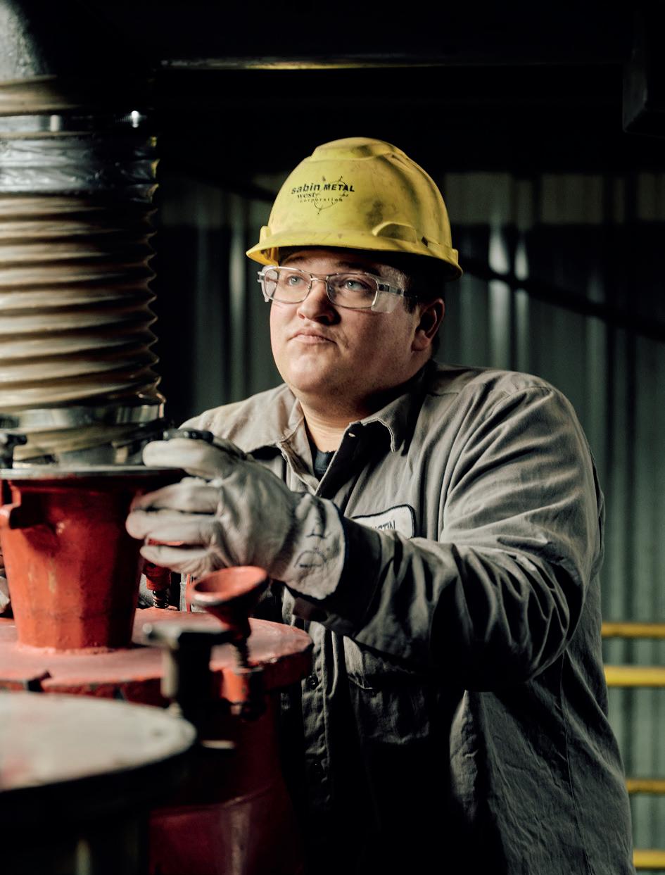
49 Minimising risk and maximising value
Brad Cook, Sabin Metal Corp., details how companies can maximise the value of their precious metal catalysts by choosing the right organisations for recovery and refining.
53 Keeping corrosion at bay
Yelena Rojas, Integrated Global Services (IGS), outlines field-applied corrosion mitigation strategies for high-temperature refinery units and demonstrates these strategies with a detailed case study.
59 From fossil fuels to electrons
Dennis Long, Watlow, discusses the challenges and opportunities for process electrification and the latest innovations in this area that are making the energy transition easier to navigate for hard to decarbonise industries.
63 Meeting the downstream market needs
Sam Eccles, Trillium Flow Technologies, considers how tailored original equipment and service pumping solutions can answer the needs of the downstream market.
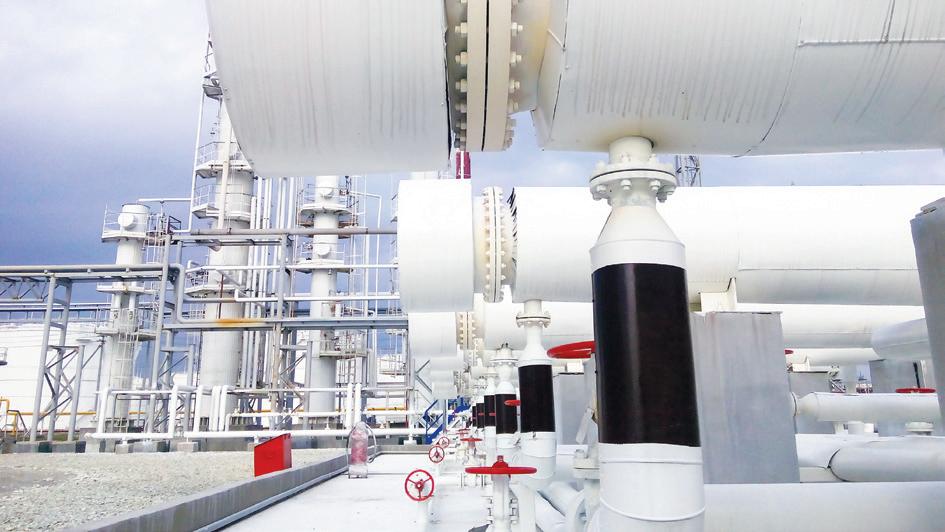
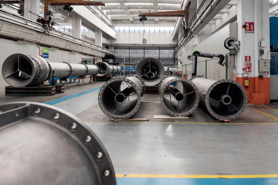
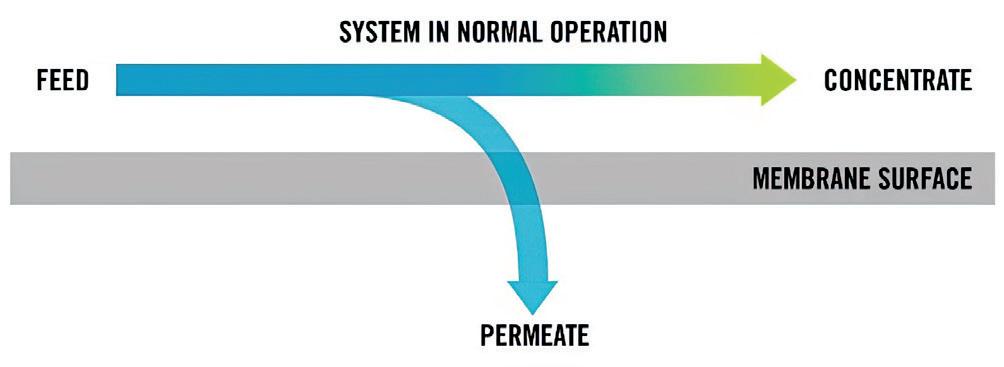
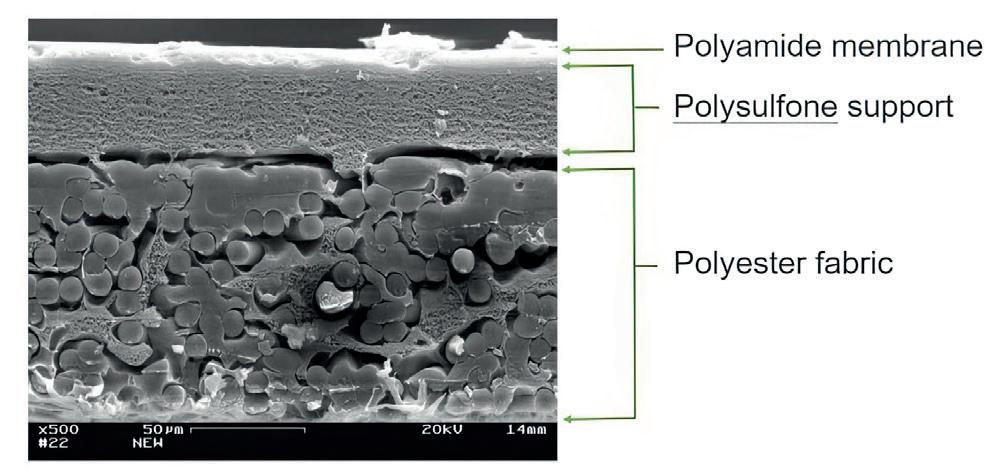
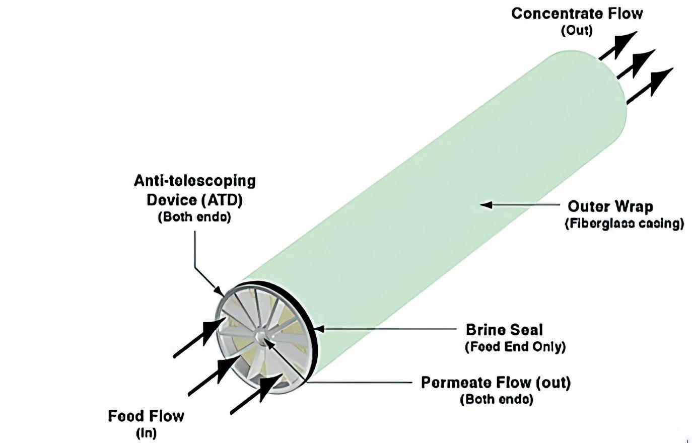
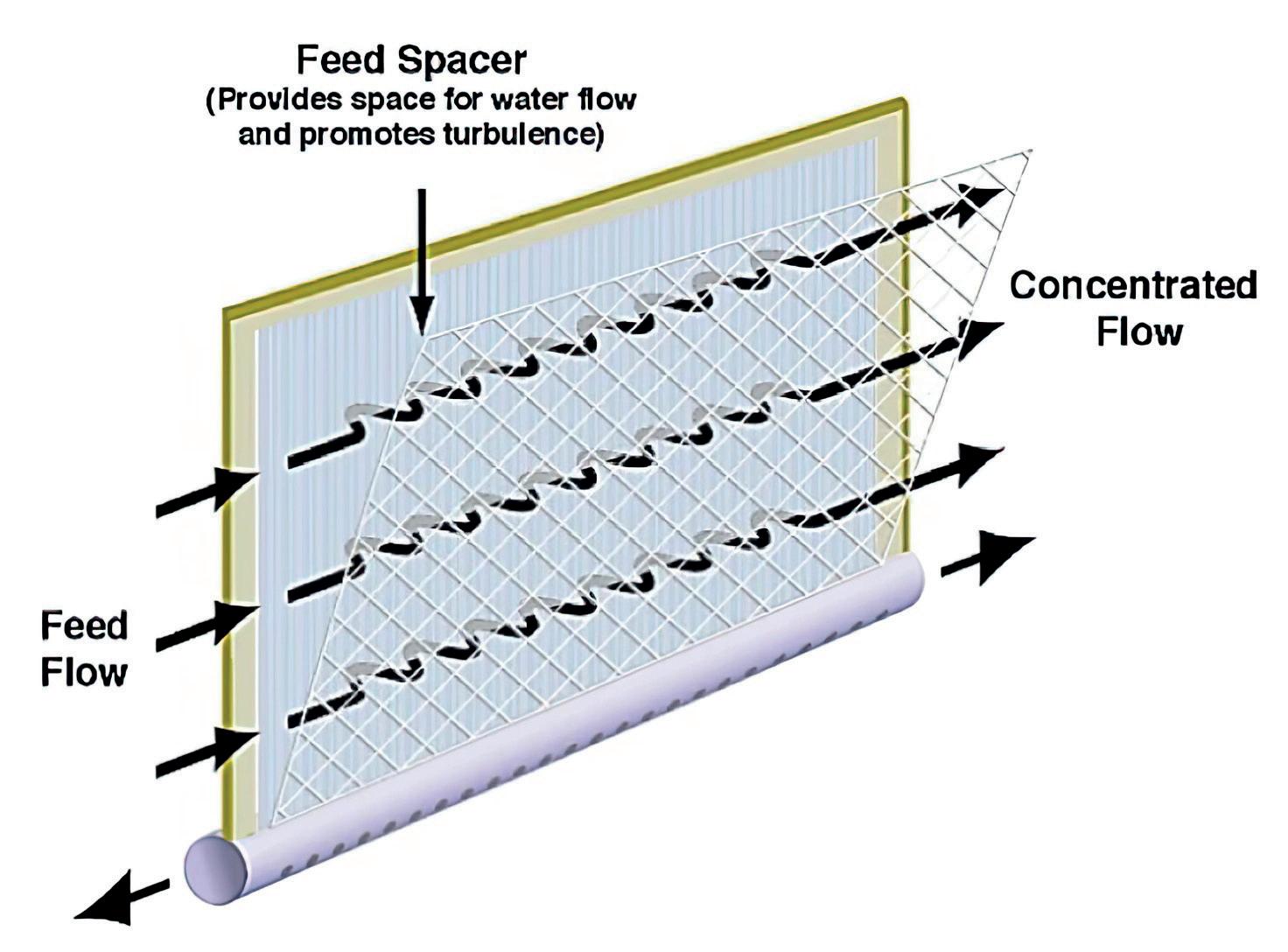
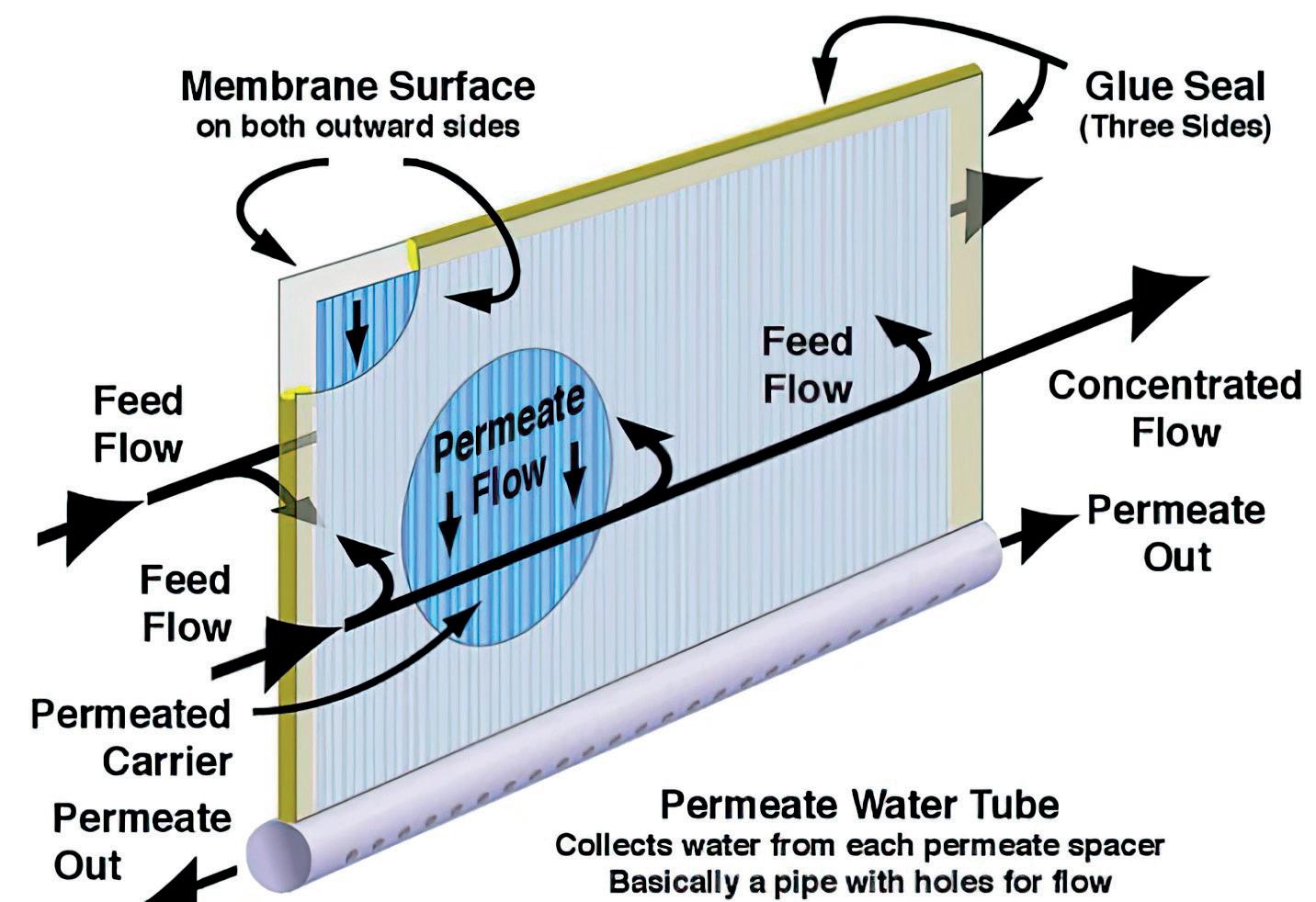
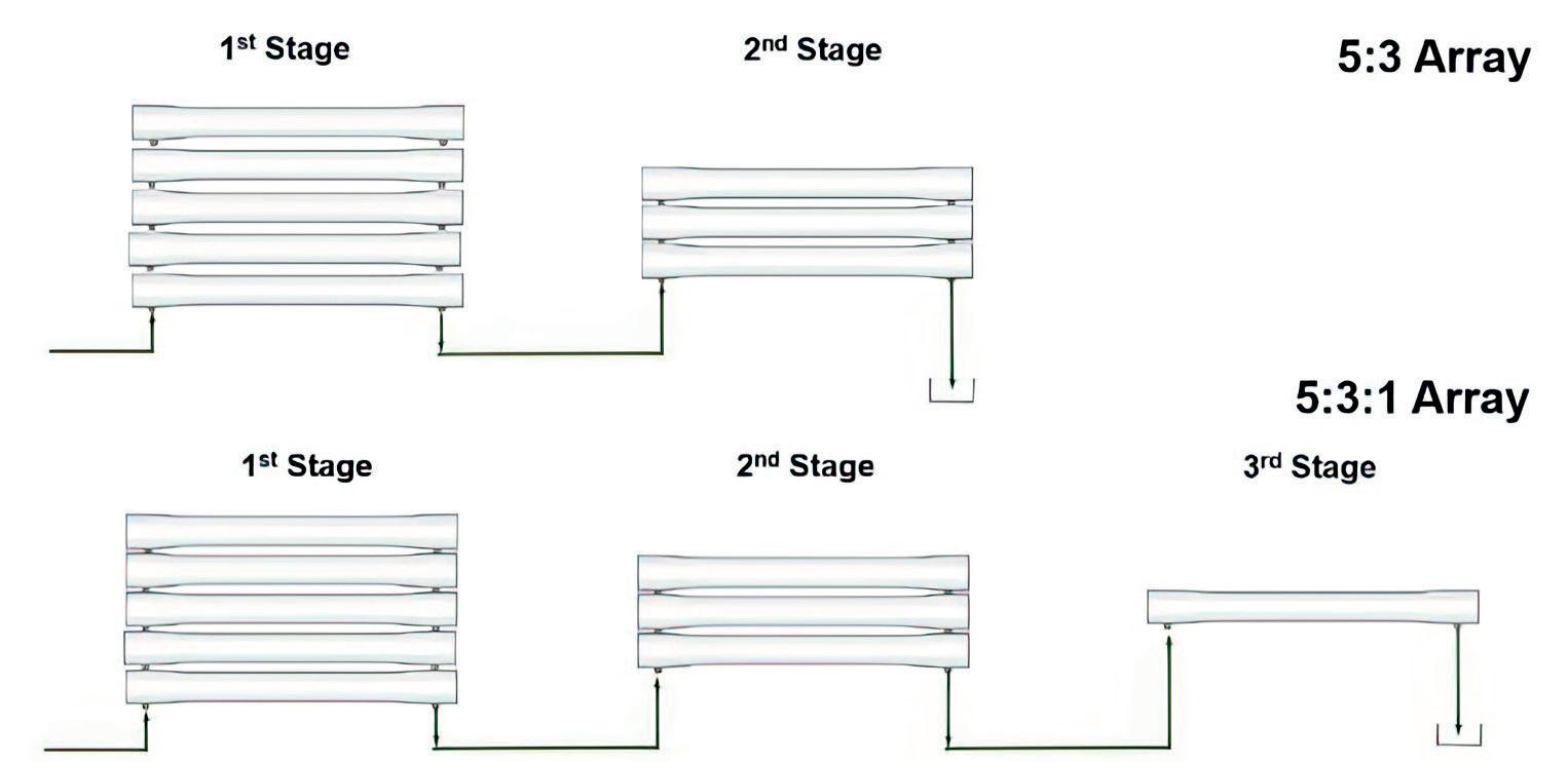
65 Mastering your membranes
Jacob Hatt, Kurita, elaborates on how reverse osmosis membranes can be designed to factor in the different requirements of key industry stakeholders.
69 A water treatment revolution
Andreina Graham, Solenis LLC, presents case studies demonstrating strategies for optimising water treatment processes.
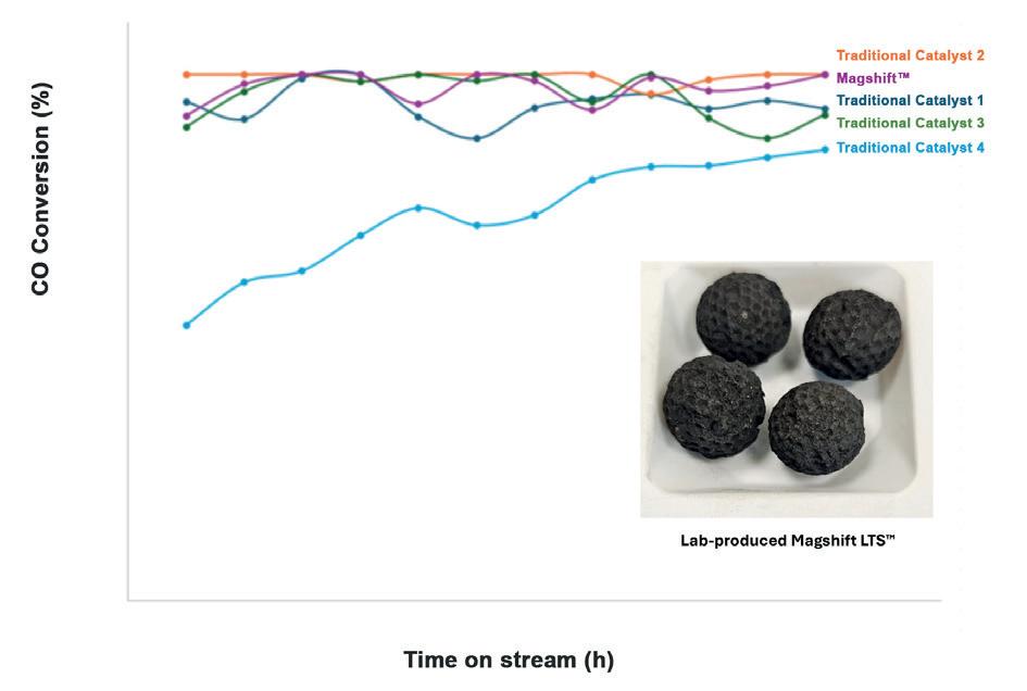
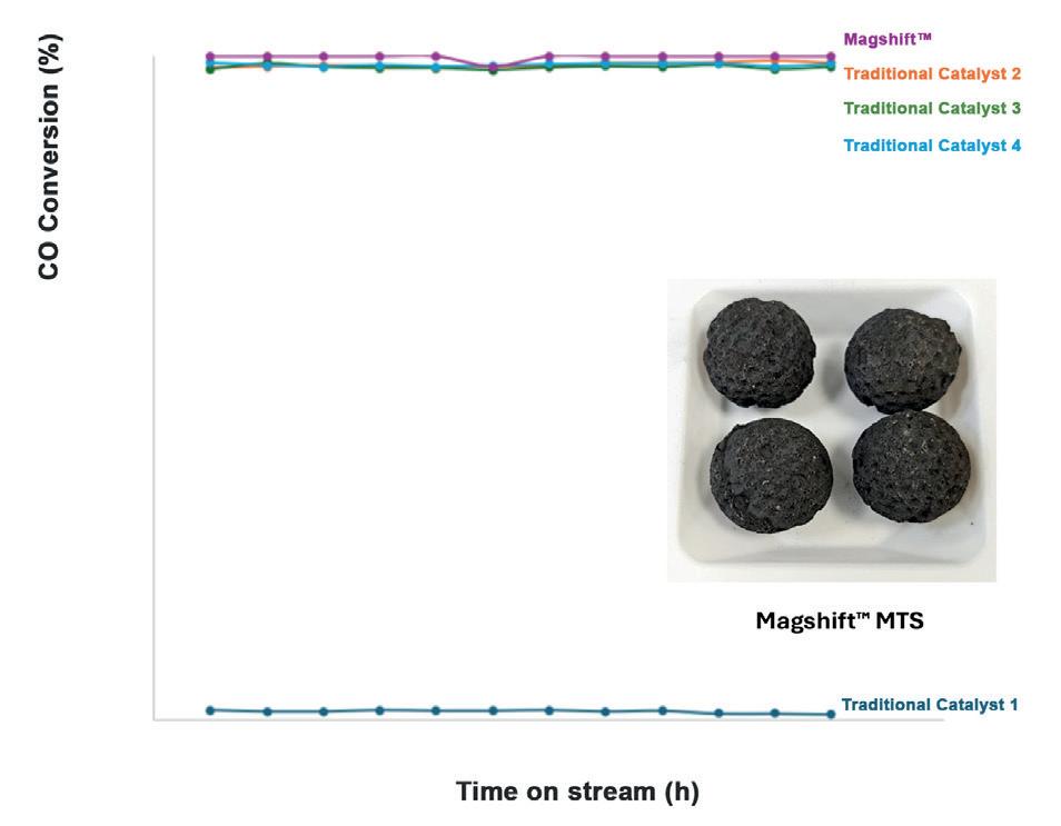
UNICAT has innovated the next generation of shift catalyst (Magshift), which has been engineered for superior performance in the water gas shift reaction. Magshift delivers: optimised porosity, extended lifetime, customisable sizing, resistance to shrinkage, and all the benefits of the revolutionary Magcat Textured Catalyst.
ET Black™ Technology
Cut your CO2 emissions by 50% with the future of carbon black production
Compliant and innovative
Meets stringent environmental regulations, keeping your business future-ready
Unparalleled flexibility
Produce all ASTM grades and specialty grades seamlessly in a single plant
Sustainable Uses thermal decomposition of aromatic oils for cleaner production
CONTACT INFO COM MENT
MANAGING EDITOR James Little james.little@palladianpublications.com
ADMIN MANAGER Laura White laura.white@palladianpublications.com
CONTRIBUTING EDITORS Nancy Yamaguchi Gordon Cope
SUBSCRIPTION RATES
Annual subscription £110 UK including postage/£125 overseas (postage airmail). Two year discounted rate £176 UK including postage/£200 overseas (postage airmail).
SUBSCRIPTION CLAIMS
Claims for non receipt of issues must be made within 3 months of publication of the issue or they will not be honoured without charge.
APPLICABLE ONLY TO USA & CANADA
Hydrocarbon Engineering (ISSN No: 1468-9340, USPS No: 020-998) is published monthly by Palladian Publications Ltd GBR and distributed in the USA by Asendia USA, 701C Ashland Avenue, Folcroft, PA 19032. Periodicals postage paid at Philadelphia, PA & additional mailing offices. POSTMASTER: send address changes to HYDROCARBON ENGINEERING, 701C Ashland Ave, Folcroft PA 19032.
15 South Street, Farnham, Surrey
GU9 7QU, UK
Tel: +44 (0) 1252 718 999
OLIVER KLEINSCHMIDT ASSISTANT EDITOR
Light. Light has been part of the human story since the very beginning. We built fires to stave off the darkness and discovered electricity to generate enough light to brighten our cities across the globe.
So what happens when the lights go out?
On 28 April 2025 the Iberian Peninsula (Spain and Portugal) experienced the largest European blackout in 20 years.¹ The complete loss of power to the region lasted over half a day and by the next morning power had been restored to almost the entire region. Blackouts pose a dangerous risk as the loss of power means that critical machinery in places such as hospitals cannot function properly, at night we are deprived of streetlights vital to safe nighttime travel, and in our modern, digital age we lose access to many electronic systems that govern our lives.
The oil and gas industry did not escape unscathed; major refineries and petrochemical producers were forced to shut down entirely. All five of Repsol’s refineries were shut down, Moeve halted operations at its chemical and refining plants, and Dow closed its plants at its Tarragona industrial complex.² It took nearly a week to bring all of the plants back online, which severely impacted revenues and production output for the industry.
In the wake of the blackout people are seeking to understand just why these incidents happen. There are, of course, several reasons as to why blackouts occur. First is what are known as ‘Acts of God’, essentially the influence of extreme weather and natural phenomena. While natural disasters can pose a level of risk, lightning strikes and solar flares have also been known to affect grid stability. Some consideration should also be given to the possibility of human interference. Whether it stems from intentional cyberattacks that have become an ever-increasing worry in the current geopolitical climate, or from simple human error, the hand of man can be at fault. There is also a simpler answer available. Grid glitches, which occur through simple mechanical failures, can cascade into more serious issues; glitches are more likely in a renewable rich grid like the one we see in Spain – owed to the fact that the system was initially built with fossil fuels in mind, not renewable energy sources.
And finally there are ‘Black Swan’ events. Incidents which occur in a cascade of small errors that simply cannot be predicted or planned for as they are, by their very nature, unpredictable. Such was the case in Spain in April. Investigations into the incident revealed that the problem came about when there was a sudden loss of power to three substations across three Spanish provinces in Granada, Badajoz, and Seville, all within seconds of each other, which led to a 2.2 GW dip in energy generation. This, in turn, triggered a series of grid disconnections.³
What this highlights is just how vulnerable these grids can be and the fact that power integration needs to be secured further. Otherwise, what is to stop a blackout of a grander, potentially continental scale, next time?
1. AMBROSE, J., ‘Blackouts can happen anywhere: how power systems worldwide can collapse’, The Guardian , (2 May 2025), https://www.theguardian.com/business/2025/ may/02/blackouts-energy-outage-risks-europe-worldwide-spain-portugal-france
2. MAHER-BONNETT, G., REIMI, I., SANDS, A., and EGOY, M., ‘Power outage hits Spanish refineries: Update’, Argus Media, ( 28 April 2025), https://www.argusmedia.com/en/ news-and-insights/latest-market-news/2682658-power-outage-hits-spanish-refineriesupdate
3. LOMBARDI, P., ‘Granada substation power loss pinpointed as ground zero of Spain’s blackout’, Reuters , (14 May 2025), https://www.reuters.com/business/energy/ power-generation-loss-spains-blackout-started-granada-badajoz-seville-2025-0514/#:~:text=A%20spokesperson%20for%20grid%20operator,grids%20not%20managed%20by%20REE.
We approach reactor optimization the way a sculptor approaches claywith vision and intention. Designed by the sharpest minds in reactor filtration, our technologies provide a front line defense that intercepts trouble before it ever hits your catalyst. Not all masterpieces hang in galleries. Sometimes, they fit in the palm of your hand. That’s the Crystaphase Experience. crystaphase.com
GUEST COM MENT
SUSAN W. GRISSOM VICE PRESIDENT & CHIEF INDUSTRY ANALYST, AMERICAN FUEL & PETROCHEMICAL MANUFACTURERS (AFPM)
The US is the world’s number one producer of crude oil and refined products, but the nation also depends on imports of both, and you might be wondering why.
Why does the US need imported oil?
US refineries process much more crude oil than US produces. While the US is producing record volumes of crude oil – almost 13.5 million bpd – US refineries are processing ~16.5 million bpd to meet US and global demand for refined petroleum products.
Most crude oil produced in the US is light, while many US refineries need heavier crude oil to maximise outputs of gasoline, diesel, and jet fuel. The light crude produced in the US is not a good replacement for the heavy crude oil that is imported primarily from Canada and Mexico.
Furthermore, the US lacks the infrastructure needed to supply US crude oil to all refineries in the country in a cost-effective manner.
Re-tooling refineries to process just US produced light crude oil and expanding infrastructure to produce and deliver that crude oil to refineries would cost billions and take decades to permit and construct.
What is the difference between heavy and light crude oils?
There are hundreds of varieties of crude oil around the world. Different types of oil require different processes to refine them into the products the US needs in the quantities it requires.
Amid the ever-evolving trade and tariffs conversations, it is important to note that policies aimed at raising costs or limiting the availability of energy imports would raise costs for consumers and threaten US energy security.
It is important to note that crude oils have different viscosities or ‘gravities’. ‘Heavy’ crude oil is more viscous, while ‘light’ crude is thinner. Crude oils also have different sulfur content. Low-sulfur crude is called ‘sweet’ and high-sulfur crude is called ‘sour’. Refineries run on a mix of crudes (often blended) to run efficiently and maximise gasoline, diesel, and jet fuel outputs. Nearly 70% of US refining capacity runs most efficiently when processing heavier crudes. That is why 90% of crude oil imports into the US are heavy.
Why are tariffs and taxes on oil imports bad for the US?
Why do US refineries need heavier crudes?
Long before the US shale boom, global production of light sweet crude oil was declining and US refineries made significant investments to process heavier crude oils that were more widely available. Heavier crude is now an essential feedstock for many US refineries. ‘Replacing’ it with light crude oil, like that produced in the US, would make these facilities less efficient and competitive, and would actually lead to a decrease in gasoline, diesel, and jet fuel production.
Amid the ever-evolving trade and tariffs conversations, it is important to note that policies aimed at raising costs or limiting the availability of energy imports would raise costs for consumers and threaten US energy security.
The US’ ability to import and export crude oil and refined products is good and worth protecting. For more information on the latest trends impacting the US refining sector and its role in the global market, be sure to register for the 2025 AFPM Summit, 25 - 28 August in Grapevine, Texas, US.
WORLD NEWS
USA | Honeywell to acquire Johnson Matthey’s Catalyst Technologies business
Honeywell has agreed to acquire Johnson Matthey’s Catalyst Technologies business segment for £1.8 billion in an all-cash transaction. Honeywell expects that the combination of the business with its Energy and Sustainability Solutions (ESS) business segment will add attractive high growth vectors to the portfolio and drive significant additional benefits.
With an expanded portfolio, Honeywell will for the first time be
able to offer customers a comprehensive solution for the production of lower emission, critical fuels including sustainable methanol, sustainable aviation fuel (SAF), blue hydrogen and blue ammonia. The resulting offerings will provide licensed technology, engineering, services and catalysts to convert hydrocarbon and renewable feedstocks to high-value end products.
USA | Woodside and Aramco sign collaboration agreement
Woodside Energy Ltd and Aramco have entered into a non-binding collaboration agreement to explore global opportunities, including Aramco’s potential acquisition of an equity interest in and LNG offtake from the Louisiana LNG project.
Woodside CEO Meg O’Neill said: “This collaboration aligns with Woodside’s strategic vision to build a diverse and resilient global portfolio. It
leverages our growing relationship with one of the world’s leading integrated energy and chemicals companies, to explore new opportunities which deliver value for both parties.”
Woodside announced a final investment decision to develop the three-train, 16.5 million tpy Louisiana LNG development on 29 April 2025. Woodside is targeting first LNG in 2029.
USA | FedEx allies with Neste for its first supply of SAF
Neste and FedEx, a worlwide express cargo airline, have agreed on the supply of 8800 t (more than 3 million gal.) of blended Neste MY Sustainable Aviation FuelTM to FedEx at Los Angeles International Airport (LAX).
It is the largest SAF purchase by a US cargo airline at LAX to-date. The fuel blend purchase will account for approximately a fifth of all jet fuel consumed annually by FedEx at LAX.
This fuel purchase by FedEx marks the first major US SAF deployment by FedEx and builds upon years of the company’s efforts to co-create innovative sustainable aviation technologies with other industry leaders. Through this agreement, FedEx has purchased blended fuel from Neste that includes a minimum of 30% neat, i.e. unblended, Neste MY Sustainable Aviation Fuel. Delivery of the fuel began in May 2025 and will continue for one year.
Global | AMETEK and Worley to deliver automated SRU solution
Anewly formed partnership between AMETEK Process Instruments and Worley Comprimo, part of Worley’s Technology Solutions, has provided sulfur recovery unit (SRU) stakeholders with critical analytical measurements, combined with advanced burner control technology, to deliver enhanced automated air control management.
The implementation of the 2ACTTM Solution ensures plant operators gain a fully automated system that minimises SRU upsets, enhances reliability, and delivers strong returns on investment. At the heart of this partnership, the 2ACT Solution offers an all-in-one approach to
advanced air control – significantly boosting SRU performance and efficiency while reducing operational costs. The solution uses AMETEK’s IPS-4 ultra-violet and infrared analyser to measure H2S, CO2, NH3, H2O, and total hydrocarbons (THCs) by continuously sampling the acid gas upstream of the SRU. The change in air demand requirement is then calculated, with main and trim air adjustments implemented automatically by the feed forward control scheme designed by Worley Comprimo.
In SRUs, tail gas/air demand analysers provide accurate concentration analysis of
sulfur compounds, providing important insight into sulfur recovery efficiency and a means of feed-back adjustments of the trim levels of air or oxygen at the thermal reactor. Plant engineers have been investigating ‘feed-forward’ analysis, which is the addition of H2S, CO2, NH3, H2O, and THC measurements of the acid gas feed to the SRU, to further optimise efficiency, reduce downtime, and comply with emissions regulations. This feed-forward analysis combined with advanced burner control technology enables the reduction in reaction time to changes in feedstocks that may cause SRU plant upsets or an unwanted increase in emissions.
WORLD NEWS
DIARY DATES
25 - 28 August 2025
AFPM Summit Grapevine, Texas, USA summit.afpm.org
09 - 12 September 2025
Gastech Milan, Italy
www.gastechevent.com
16 - 18 September 2025
Turbomachinery & Pump Symposia Houston, Texas, USA tps.tamu.edu
18 September 2025
TSA Tank Storage Conference and Exhibition Coventry, UK tankstorage.org.uk/conference-exhibition
21 - 24 September 2025
GPA Midstream Convention San Antonio, Texas, USA www.gpamidstreamconvention.org
23 - 25 September 2025
1st Annual Aboveground Storage Tank Conference & Trade Show
Long Beach, California, USA www.nistm.org
20 - 23 October 2025
API Storage Tank Conference & Expo Phoenix, Arizona, USA events.api.org/2025-storage-tank-conference-expo
03 - 06 November 2025
ADIPEC
Abu Dhabi, UAE www.adipec.com
17 - 20 November 2025
ERTC Cannes, France
worldrefiningassociation.com/event-events/ertc
09 - 11 December 2025
18th Annual National Aboveground Storage Tank Conference & Trade Show
The Woodlands, Texas, USA www.nistm.org
USA | Chevron Phillips Chemical sells shares in polyethylene manufacturing JV
Chevron Phillips Chemical (CPChem) has announced that the shareholders of Chevron Phillips Singapore Chemicals (CPSC) have agreed to sell 100% of their shares to Aster Chemicals and Energy through its affiliate Chandra Asri. Aster is a joint venture (JV) company between Chandra Asri and Glencore.
CPSC owns and operates a high-density polyethylene manufacturing facility on Jurong Island, Singapore, with a production capacity of 400 000 tpy. Approximately
150 employees of CPSC are expected to have the opportunity to join Aster.
“CPSC is an excellent strategic fit for Aster, and we are confident the business will thrive as part of its portfolio,” said CPChem Executive Vice President of Commercial, Justine Smith. “With this transaction, we are optimising our asset portfolio to ensure we remain competitive and continue to serve as the supplier of choice to our global customers.”
The transaction remains subject to customary closing conditions.
Canada | TotalEnergies agrees to export LNG from the Ksi Lisims LNG Project
TotalEnergies has signed a sales and purchase agreement (SPA) with Ksi Lisims LNG for the purchase of 2 million tpy of LNG for 20 years from the future liquefaction plant, subject to the final investment decision of the project.
In parallel, TotalEnergies has acquired a 5% stake in Western LNG, the developer, shareholder, and future operator of the Ksi Lisims LNG project. This acquisition grants TotalEnergies the option to increase its stake in
Western LNG and/or take a direct stake in the plant up to approximately 10% when the final investment decision is made.
The Ksi Lisims LNG project, with a capacity of 12 million tpy, is located on the Pacific coast of Canada (British Columbia), giving it privileged access to Asia, the largest LNG market. Fully electrified and powered by hydroelectricity, Ksi Lisims LNG will be one of the lowest CO2-emitting LNG projects in the world.
Brazil | Petrobras begins operation of natural gas processing unit
Petrobras has announced that the second module of the natural gas processing unit (UPGN) of the Boaventura Energy Complex, located in Itaboraí in Rio de Janeiro, has entered commercial operation.
Added to the first module, inaugurated in 2024, the unit’s total processing capacity reaches 21 million m³/d.
The UPGN is part of Petrobras’ Route 3 Integrated Project, through
which natural gas from pre-salt fields in the Santos Basin is transported. This is a rich gas which, after processing, generates natural gas, LPG and C5+.
Since November 2024, Petrobras has been commercially operating the UPGN of the Boaventura Energy Complex, contributing to increasing the supply of natural gas to the domestic market and reducing dependence on imports.
INTRODUCING
Grace Essential Articles, Vol. 1
Grace is proud to present a meticulously curated collection of our most requested and referenced articles from the past four decades. For over 80 years, Grace has been at the forefront of FCC catalyst development, driven by innovation and a long history of looking ahead.
What’s Inside?
Timeless Knowledge:
Articles are presented as originally published, preserving authenticity and demonstrating enduring relevance.
Expert Insights: Grace experts provide introductions, reflecting on each article’s historical impact and modern significance.
Diverse Topics:
Explore key drivers of catalyst value, including traditional fuel production, on-purpose propylene, and the decarbonization value chain.
Get Your Copy Today!
Read or download Grace Essential Articles, Vol. 1 now and tap into the collective knowledge of the catalysis experts at Grace.
Gordon Cope, Contributing Editor, provides necessary insight into the burgeoning oil and gas industry across Central
The vast region of Central and South America is home to some of the largest and most profitable oil and gas resources in the world. It also contains a wide spectrum of jurisdictions that approach their assets with everything from an economic blessing to rank kleptocracy.
Mexico
Mexico, with 6 billion bbl of crude reserves, has been wrestling with declining production for the last several decades; output has plunged from 3.4 million bpd in
and South America.
2004 to 1.6 million bpd in 2024. The reason is twofold; natural decline in its supermajor fields like Cantarell, and a lack of exploration investment by state-owned Pemex. While international participation was promoted by former President Nieto, his successor, President Andrés Manuel López Obrador (AMLO), discouraged foreigners and doubled down on its debt-ridden state champion.
A case in point is the Dos Bocas refinery in the state of Tabasco. While Pemex has sufficient nameplate capacity at its six existing refineries to meet the
country’s diesel and gasoline consumption, a lack of investment in maintenance, theft, and corruption, have resulted in low utilisation rates, forcing the country to import over 380 000 bpd of fuel. AMLO’s solution was to build a new, 380 000 bpd refinery in the state of Tabasco. AMLO officially opened the US$8 billion facility in 2022, but it has yet to produce more than token amounts of fuel. Analysts note that it was built using antiquated plans on unstable swampland using inferior technology; the price tag has also risen to over US$20 billion.
LNG holds greater potential. The west coast of Mexico is thousands of kilometres closer than the US Gulf Coast to markets in Asia and obviates the need for exporters to pass through the Panama Canal. There are six proposed export terminals located on the Pacific and three more on the Gulf Coast. Sempra Energy’s Energía Costa Azul (ECA) LNG, located in Baja California, is a former LNG import site. The 3 million tpy train is expected to be commissioned by 2025, and could ultimately be expanded to 12 million tpy. The Mexico Pacific Ltd (MPL) LNG project is located on the Sea of Cortez. The latest plan is to build three trains totalling 14.1 million tpy of capacity in Phase 1, and a further three trains in Phase 2, doubling capacity to 28.2 million tpy. While the Biden Administration’s recess on LNG had a chilling, knock-on effect on Mexican plans, President Trump cancelled the pause, allowing proposals to proceed once again.
President Claudia Sheinbaum, AMLO’s chosen successor, is not expected to depart from the previous president’s prioritisation of Pemex. In February, 2025, she announced an ambitious programme in which the state-owned company will drill over 200 exploration wells in an attempt to increase gas output from 3 billion ft³/d to 5 billion ft³/d by the end of her term in 2030.
Argentina
Argentina’s oil and gas sector has been propelled to dizzying heights by the Vaca Muerta unconventional shale play, which contains an estimated 16 billion bbl of oil and over 300 trillion ft³ of gas. According to the US Energy Information Administration (EIA), by late 2024, production had risen to 428 000 bpd and 3.8 billion ft³/d from virtually nothing a decade ago.1 But the play has the potential to surge to 1 million bpd and 5 billion ft³/d by 2030.
Those prospects have ignited a spectrum of midstream and downstream projects. In order to deliver crude and gas to markets, several major pipelines are being built. The 800 million ft³/d Nestor Kirchner gas line was completed in 2023, with an additional 500 million ft³/d of capacity now under construction. In May 2024, state-owned YPF began building the 390 000 bpd Vaca Muerta Sur crude pipeline. The 600 km line is designed to move unconventional crude from Neuquén province to a terminal in Punta Colorada in the Rio Negro province.
Lucrative export markets beckon. In late 2024, YPF announced that it would be replacing Malaysia’s Petronas with the Netherlands-based Shell in an ambitious, US$50 billion plan to export LNG. Argentina LNG will transport gas from the Vaca Muerta through dedicated gas pipelines to the coastal province of Rio Negro. The first
phase of 10 million tpy will use floating LNG vessels, while future phases envision the construction of onshore LNG facilities.
Refineries are also finally getting upgraded. Argentina has around 600 000 bpd nameplate capacity, but still imports over 100 000 bpd to meet demand. YPF, which accounts for around half of the country’s capacity, is spending more than US$2 billion to increase production at the 189 000 tpd La Plata refinery near Buenos Aires and the 105 000 bpd Lujan de Cuyo refinery in Mendoza. By 2024, the company was producing a record 310 000 bpd of gasoline and diesel, and expects to add another 20 000 bpd of output in 2025.
The success of the oil and gas sector is also due to federal support. President Javier Milei (a free-market economist who assumed office in December 2023), passed legislation designed to encourage investment in major energy projects. The Basis Law calls for significant tax breaks on capital investments, as well as exemption from export taxes up to three years. The aim is to create a favourable environment for energy infrastructure development.
Colombia
Colombia is South America’s third largest oil producer, with an output of approximately 780 000 bpd (and 1 billion ft³/d of associated gas). It has only eight years of crude and gas reserves left before it runs out, however, so the country’s oil and gas sector was heartened when Ecopetrol announced the discovery of a giant offshore gas field. The Sirius-2 well, located 77 km offshore in the Caribbean Sea, discovered an estimated 6 trillion ft³ of gas, doubling the country’s reserves overnight. Ecopetrol and partner Petrobras have initiated the environmental and regulatory processes in order to tie the field back to shore facilities near Santa Marta in the department of Magdalena. They estimate that it will cost over US$4 billion to bring the field online by 2027. Production is expected to approach 500 million ft³/d over a 10 year period.
Guyana
Over the last decade, Guyana has risen to one of the continent’s largest oil exporters. Currently, a consortium led by ExxonMobil produces approximately 650 000 bpd; with the upgrades to its three FPSOs and the arrival of a fourth vessel, production is expected to rise to 940 000 bpd in 2025. With the addition of further commissioned FPSOs, output is expected to reach 1.4 million bpd by the end of the decade.
A significant amount of associated natural gas is also produced. Most is currently reinjected to maintain reservoir pressure, but Guyana would like to commercialise the gas in order to lower electricity rates and reduce power blackouts. It negotiated an agreement with ExxonMobil to deliver gas from the Liza project via a 225 km offshore pipeline costing approximately US$1 billion and a 300 MW electricity complex near the capital of Georgetown, estimated to cost US$759 million. Over the longer-term, the government is also looking to monetise the gas by building LNG and fertilizer plants; ExxonMobil and partners have plans to produce up to
Polymer with purpose
Sulzer’s CAPSUL™: using Sulzer’s technology for PCL (Polycaprolactone) production to unlock a brighter future with sustainable processes at scale
By implementing Sulzer’s CAPSUL technology you can make an impact with biodegradable polymer for packaging, adhesives, coatings and more.
• Scale efficiently and sustainably
• Next-gen technology to stay ahead of the competition
• Seamlessly add into existing offering
• Do good for your business, do good for the environment
sulzer.com/chemtech
1.5 billion ft³/d of gas from its Longtail field when the project comes on-stream later in the decade.
Suriname
Furthermore, neighbouring Suriname is about to get a taste of Guyana’s success. In November 2024, TotalEnergies made a final investment decision on developing its discoveries in Block 58, located 150 km off the coast of the Atlantic nation. The French-based company announced that it would spend up to US$10 billion to develop the GranMorgu project, consisting of the Sapakara and Krabdagu fields, which hold over 750 million bbl of crude. An FPSO capable of producing 220 000 bpd is forecast to begin production in 2028. The ship is being designed to accommodate future tie-back opportunities as exploration results warrant.
Venezuela
Venezuela should be a Latin American powerhouse in the oil and gas sector. With an estimated 304 billion bbl of reserves, the country once produced over 3 million bpd, but has seen output plummet to under 1 million bpd. Much of the problem can be attributed to mismanagement, a lack of maintenance, and blatant corruption.
As if Venezuela does not have enough to worry about, the Trump Administration has involved itself. In March 2025, the White House cancelled the agreement between Chevron and Venezuela that allowed the former to produce oil in the country despite sanctions. In conjunction with state-run PDVSA, Chevron pumps approximately 200 000 bpd, about one-fifth of the country’s production. Most of the output is shipped to refineries on the US Gulf Coast, which are configured to upgrade the heavy crude. In addition, the US Treasury cancelled licences that allowed foreign firms to export oil from the country, and Trump threatened to place a 25% tariff on goods entering the US from any country that bought their oil. The political moves are seen by analysts as a way to pressure the Maduro regime into democratic reforms. Opposition leader María Corina Machado hailed the move as a way to remove funds used by the regime to persecute its enemies. Critics said it would only harm the plight of already desperately-poor citizens.
Brazil
Petrobras continues to be a significant engine of growth in Brazil. Over the last year, it has grown its oil reserves by 500 million bbl, to a total of 11.4 billion bbl. It has earmarked US$111 billion in spending for the next five years, including US$77 billion for exploration and production. In 2024, production surpassed 2.2 million bpd of crude, and 2.7 million bpd/e.
Brazil now produces more than 4.4 million bpd of crude liquids, with significant increases expected over the next 18 months. A new field is projected to come on-stream in late 2024 when the 100 000 bpd FPSO Maria Quiteria arrives at the Jubarte field in the Campos Basin’s pre-salt layer. Three other fields are
expected to see new FPSO capacity in 2025; 400 000 bpd at Buzios and 180 000 bpd at MERO4.
Petrobras’ also recently announced that the expansion of Train One at its 100 000 bpd Abreu e Lima (RNEST) refinery in northeast Brazil was completed in March 2025. The work included the installation of an atmospheric emissions abatement (SNOX) unit that converts sulfur oxide and nitrogen oxide into marketable sulfuric acid. Now that it is fully operational, the unit will help increase output to 130 000 bpd of low-sulfur diesel. Petrobras has plans to add a second 130 000 bpd train, doubling production to 260 000 bpd by 2028.
Green energy
Countries in Central and South America are taking a wide range of approaches to green energy. Colombia, which relies on oil and gas for over 60% of its energy needs, is looking to diversify into clean energy. In 2024, it awarded new contracts to add almost 4500 MW of solar power by 2028. It has also received interest from nine companies to install up to 3000 MW of offshore wind projects to meet its rapidly growing domestic consumption of electricity. Argentina, blessed with abundant wind, has expanded its network of wind farms to approximately 3300 MW, which represents almost 20% of its energy mix.
In June 2024, the government of Brazil’s Ceará state announced it had reached an agreement with Madrid-based FRV to invest US$5 billion to build the H2 Cumbuco plant in Ceará’s Pecém Industrial and Port Complex in northeast Brazil. The first phase of the project will have a capacity of 400 000 tpy of ammonia, eventually rising to 1.6 million tpy. The state has also signed five other memorandums of understanding (MoUs) with international firms, including bp and Fortescue. The output is primarily destined for European markets.
On a contrary note, Shell, which had obtained the authorisation to build several utility scale solar farms in central and northeast Brazil, recently approached the country’s energy regulator and requested their permission be revoked. Analysts point to a regional oversupply of electrical energy, a challenging regulatory landscape, and weak growth in demand for renewables as economic justification for the move. In addition, Shell, like other IOCs, is pivoting away from the new generation of energy and back to its traditional focus on oil and gas.
Conclusion
In conclusion, the approaches that governments take in Central and South America have a profound effect on the continent’s oil and gas sector. The prospects of Argentina’s Vaca Muerta play are enhanced by the business-friendly administration of President Milei, while leftist regimes in Brazil and Colombia seek to harness oil and gas revenues for social agendas. Regardless, the region offers immense opportunity for development as both the population and energy consumption increase.
Ghoncheh Rasouli, KBC (A Yokogawa Company), analyses process simulation’s role in advancing plastic-to-olefin technologies.
The growing plastic waste crisis and the limitations of traditional recycling methods have driven the search for innovative and scalable solutions. Converting plastic waste into olefins presents a promising pathway to close the materials loop, reduce environmental impact, and support the transition to a circular economy. Plastic-to-olefins (PTO) conversion enables the transformation of post-consumer waste into high-value petrochemical feedstocks, aligning with regulatory pressures, market dynamics, and global decarbonisation efforts.
This article outlines the closed-loop PTO process, detailing critical steps including plastic pyrolysis, hydroprocessing, and steam cracking. It highlights critical technical challenges such as feedstock variability, furnace adaptability, and process optimisation. To address these complexities, a simulation-based methodology was employed, leveraging advanced software to model process units, predict operational challenges, and optimise key parameters for improved efficiency and sustainability.
The plastic waste crisis and the increasing demand for sustainable solutions have driven the development of innovative methods for recycling and reusing plastics. With nearly 380 million t of plastic produced annually¹ and the majority ending up in landfills, oceans, or incinerators, the need for scalable and sustainable recycling solutions has never been more urgent. Traditional mechanical recycling techniques struggle with mixed or contaminated feedstocks, limiting their effectiveness. In response, chemical recycling methods – especially those leveraging pyrolysis and advanced hydroprocessing – have emerged as transformative technologies for closing the loop on plastic use.
One of the most promising advancements in this field is the closed-loop plastic waste-to-olefins process. By chemically converting post-consumer plastic waste into olefins, which are the fundamental building blocks for new plastic products, this technology enables circularity at scale. It also reduces the carbon footprint associated with virgin olefin production. This approach focuses on converting waste plastics into valuable olefins, which serve as the building blocks for producing new plastics and other petrochemical products. This article explores the technological advancements, operational case studies, and best practices in plastic waste recycling using simulation, optimisation, and decarbonisation techniques.
Importance of plastic waste to olefins conversion
Plastic pollution has reached alarming levels worldwide, with millions of tons of waste accumulating in landfills and oceans. Traditional recycling methods have limitations in
processing mixed and contaminated plastics, leading to inefficiencies in waste management. Additionally, the olefin industry faces significant energy consumption and carbon emissions challenges, with CO2 emissions ranging from 0.85 to 1.8 t per ton of ethylene produced.2 Finding an economically viable and sustainable alternative is crucial for reducing the industry’s carbon footprint while maintaining production efficiency.
Several key drivers are accelerating the adoption of PTO conversion technologies, positioning them as a critical solution in the transition toward a circular and low-carbon economy. One of the primary forces is regulatory pressure, as governments worldwide introduce increasingly stringent environmental regulations. These policies are aimed at reducing landfill dependence, cutting greenhouse gas emissions, and promoting resource efficiency – effectively encouraging industries to adopt circular economy practices.
In parallel, market dynamics are reinforcing this shift. The global recycled plastics market is experiencing robust growth, with a compound annual growth rate (CAGR) of approximately 9.5%.3 This surge is particularly notable in the Asia-Pacific region, where rising demand for sustainable materials and strong manufacturing activity are driving investment in recycling and chemical conversion technologies.
Additionally, corporate and national decarbonisation commitments are influencing strategic decision-making across sectors. As more industries align their operations with net zero targets, the conversion of plastic waste into olefins emerges as a viable and scalable pathway for reducing carbon footprints while recovering valuable resources and advancing sustainability objectives.
Overview of closed-loop plastic waste to olefins
A closed-loop system ensures that plastic waste is continuously processed and reused without loss of material value. Unlike traditional linear models that result in plastic disposal, this approach reintegrates wastederived olefins back into the supply chain.
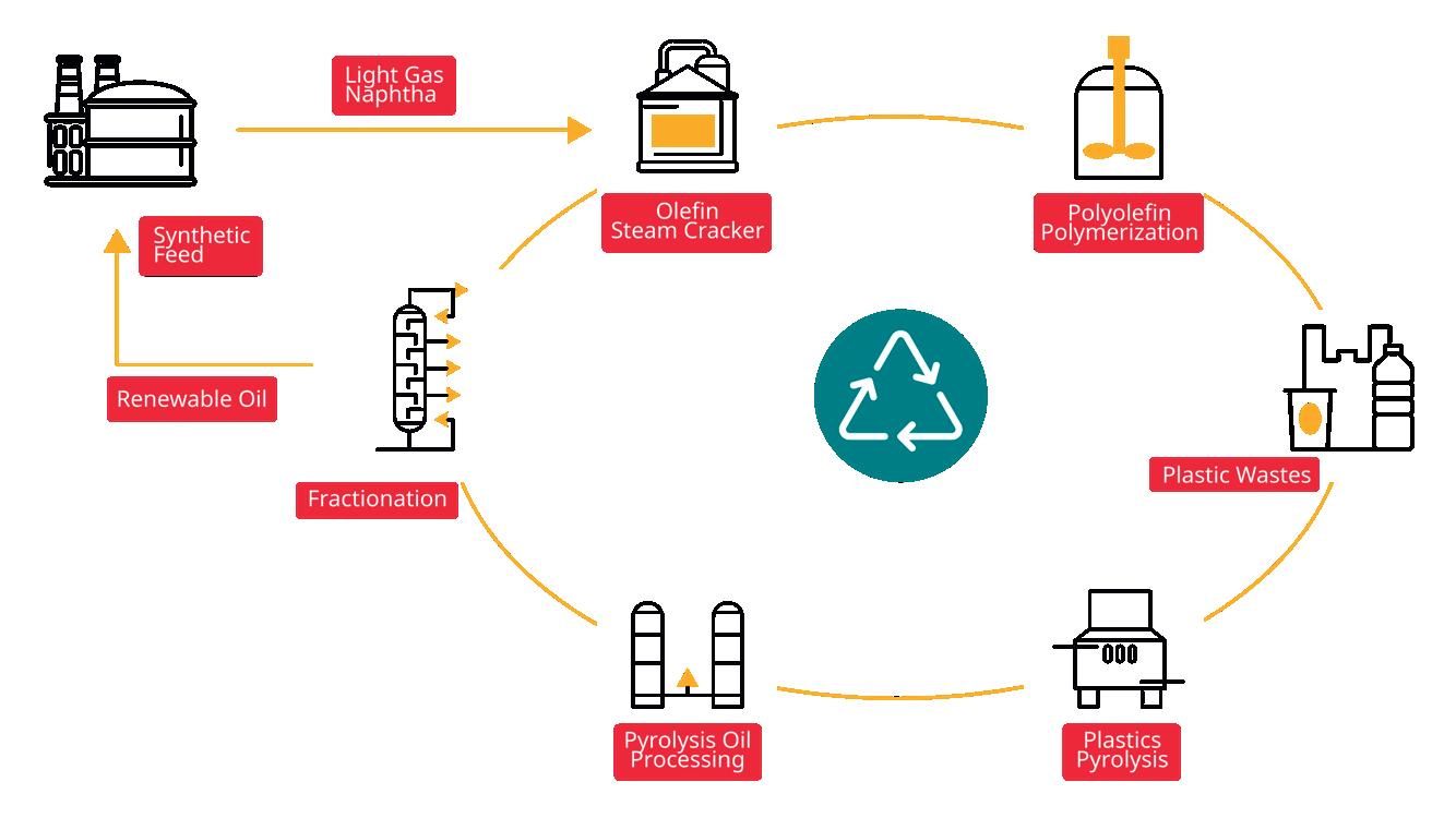
The process of converting plastic waste into valuable olefins involves a series of integrated steps designed to maximise waste recovery and ensure product quality, as shown in Figure 1. Initially, plastic waste undergoes collection and sorting, where materials are categorised according to polymer type and contamination levels to ensure feedstock consistency. Following this, the sorted plastics enter the chemical recycling phase, typically through pyrolysis, where thermal cracking breaks down the polymers into pyrolysis oil under controlled conditions. Pyrolysis is a mature thermochemical process increasingly applied to mixed plastic waste (MPW), polyethylene (PE), polypropylene (PP), polystyrene (PS),
Figure 1. Lifecycle process of plastic waste into olefins and polyolefins.
WABT Gain (°C)
Feed Sulfur: 1000 ppmwt (10-15% Improvement in Catalyst Cycle Length)
and polyethylene terephthalate (PET).4 The feedstock composition strongly influences product yields.
To maintain desirable product yields, it is important to monitor and optimise the pyrolysis reactor’s key operational variables, including temperature, residence time, and pressure.
The second step is hydroprocessing the pyrolysis oil. The pyrolysis oil contains impurities that require refining. Advanced hydrotreatment and hydrocracking methods remove contaminants, improving the pyrolysis oil quality.
The third step of the process is steam cracking the naphtha for olefin production. Synthetic naphtha is fed into steam crackers, where it is thermally cracked into valuable olefins such as ethylene and propylene. The efficiency of this process is enhanced by simulation-driven optimisation, which predicts reactor behaviour, coking rates, and energy consumption.
The olefin can be sent for further fractionation and finally to the polyolefin unit for polymerisation. The olefins produced are separated and polymerised to form new plastics, completing the closed-loop cycle. Integrating carbon capture and utilisation (CCU) technologies minimises the overall CO2 footprint of the process.
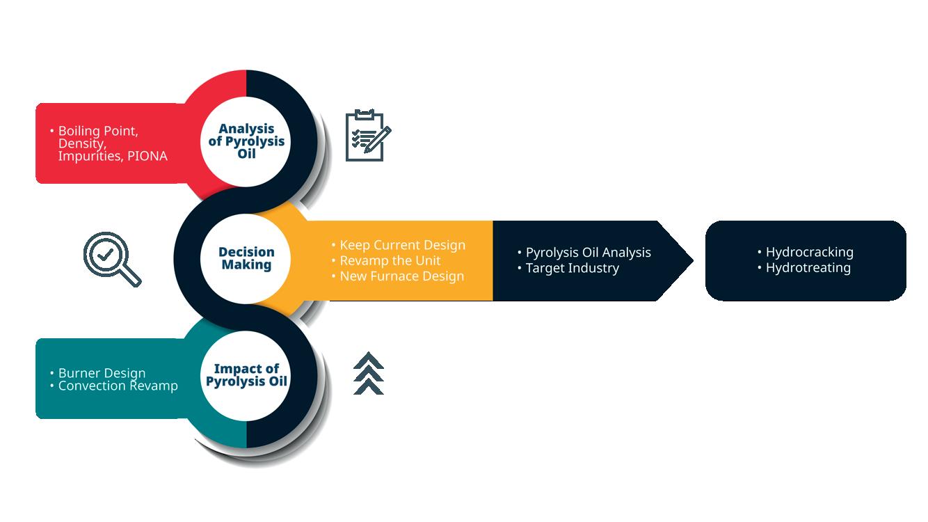
The integration of recycled plastic-derived pyrolysis oil into olefin production represents a promising pathway toward more sustainable operations, yet it also presents significant challenges that technologists and operators must address, as summarised in Figure 2.
These challenges include the complex analysis and variability of pyrolysis oil, which consequently affects decisions around necessary downstream processing and feed preparation. Understanding how this unconventional feed affects steam cracker performance – particularly product yield, coking behaviour, and equipment compatibility – is critical to ensuring reliable, efficient operation, including potential burner and convection section upgrades. The performance of the crackers’ convection section and the long-chain olefinic content in the pyrolysis oil can impact ethylene and propylene yields, reduce radiation duty, and increase coke formation. Strategies such as blending pyrolysis oil with naphtha and
designing furnaces capable of processing wide boiling range feeds help mitigate these challenges.
One of the foremost concerns is the variability and complexity of pyrolysis oil composition. To assess its suitability, a detailed characterisation is essential. This includes analysing boiling point distribution, density, impurity levels, and hydrocarbon composition using paraffins, isoparaffins, olefins, naphthenes, and aromatics (PIONA) analysis. These factors influence how the feedstock behaves during thermal cracking and directly affect product yield, process stability, and fouling tendencies.
A key consideration in the transition to pyrolysis oil is the capability of existing steam cracker furnaces. Many furnaces operating today are designed for traditional light naphtha feedstocks, raising concerns about whether these units can handle the preheating and evaporation requirements of heavier or olefin-rich pyrolysis oils. The convection section’s heat transfer efficiency, susceptibility to coking, and the behaviour of the transfer line exchanger under new conditions must all be re-evaluated. If the current design proves inadequate, options include upgrading the existing furnace, introducing feedstock pre-treatment systems, or developing entirely new furnace configurations tailored to the characteristics of pyrolysis oil.
These technical complexities directly impact plant performance. For example, long-chain olefinic content in the pyrolysis oil can reduce ethylene and propylene yields, lower radiant heat duty, and accelerate coke deposition –ultimately shortening furnace run lengths and increasing maintenance frequency. Moreover, blending strategies, such as adjusting the ratio of pyrolysis oil to naphtha, require careful optimisation to maintain desired product slates without compromising equipment integrity.
In this evolving landscape, the technologist’s role is central. These experts evaluate how pyrolysis oil will affect overall plant operation and guide decision-making processes that align with both environmental targets and operational constraints. By interpreting complex feedstock behaviour, modelling process impacts, and proposing viable integration pathways, they provide critical insights that support the development of sustainable olefin production systems. In doing so, they help bridge the gap between the ambition of circular economy initiatives and the technical realities of refinery operations.
Successfully integrating recycled pyrolysis oil into olefin production requires a holistic view of feed characterisation, furnace adaptability, and product optimisation under sustainable operation targets.
Methodology
In the pursuit of enhanced process efficiency, simulation and optimisation play a critical role in processing the PTO conversion pathway. Advanced process simulation tools, such as Petro-SIM®, enable precise control and optimisation of key parameters like
Figure 2. Plastic-derived pyrolysis oil into olefin.
temperature, pressure, and residence time, ensuring high efficiency, optimal yields, and consistent product quality. By leveraging platforms like Petro-SIM and other advanced modelling environments, operators can proactively address performance limitations and monitor key performance indicators (KPIs) that are often difficult to measure in real-time operations, helping to quickly identify and correct process deviations.
Additionally, decarbonisation strategies, including carbon capture integration and energy recovery techniques, are increasingly incorporated into process models to support low-emission or net zero production goals. This holistic approach not only improves economic viability but also advances environmental sustainability in the PTO transformation process.
A leading petrochemical company implemented a process simulation tool, like Petro-SIM, to enhance the performance of its steam crackers. Applying optimisation strategies, it investigated and analysed the effect of different scenarios related to the energy efficiency and CO2 emissions reduction of the steam cracker, as follows: changing hydrocarbon feed ratio (S/C), coil outlet temperature (COT), excess air, fuel composition (fuel switching). Optimisation results show energy savings of about 4.6% and emission reduction by 44%, while achieving a marginal gain of about 3.7%.
In this study, the impact of various feed types on KPIs was investigated. To accurately analyse the effect of
different feed types on steam cracker performance across various scenarios, individual optimisation was performed, as cracker performance varies with changing process conditions.
Results
Four different feed scenarios were evaluated to assess the impact of plastic waste integration into olefin production: Case 1: conventional naphtha, Case 2: atmospheric gas oil (AGO), Case 3: (PE + VGO) pyrolysis oil (conversion blending of PE and vacuum gas oil (VGO) to pyrolysis oil), Case 4: (PE + VGO) pyrolysis oil upgraded via hydrocracking (HDC) to naphtha.
The KPIs for each case are summarised in Table 1, with results shown in Table 2.
Ethylene and propylene yields are crucial metrics for evaluating cracker performance under various feed types. Case 4, involving hydrocracked pyrolysis oil upgraded to naphtha, achieved the highest ethylene + propylene yield at 40.2 wt%, outperforming both traditional fossil-based feeds (naphtha and AGO) and untreated pyrolysis oil. In contrast, Case 3 (direct pyrolysis oil) showed a lower yield of 35.3 wt%, indicating that upgrading significantly enhances olefin production efficiency.
Severity, expressed as the propane-to-ethylene (P/E) ratio, reflects cracking severity and feedstock reactivity. Case 3 demonstrated the lowest severity at 0.43 wt/wt, suggesting a lower severity requirement when using untreated pyrolysis oil. In comparison, traditional naphtha
MODULAR BUILDS ENGINEERED TO ADAPT
Giving Industrial Sites the Edge for 25 Years and Counting
Faster builds, lower costs, less waste and adaptability. When jobs demand more, modular delivers. Hunter’s custom modular structures provide unmatched support for today’s industrial needs and tomorrow’s challenges. Whether you’re working with tight footprints, rapid timelines or evolving project needs, Hunter has you covered on every front .
and AGO required higher severity levels (0.55 - 0.558 wt/wt), while the hydrocracked case (Case 4) exhibited slightly higher severity (0.57 wt/wt) relative to untreated pyrolysis oil.
Radiation efficiency, a measure of furnace heat transfer performance, was relatively consistent across the cases, ranging from 38.63% to 41.7%. The highest radiation efficiency was observed with conventional naphtha (41.7%), whereas hydrocracked pyrolysis oil in Case 4 had the lowest radiation efficiency (38.63%), likely due to differences in feed physical properties affecting heat transfer characteristics.
Energy intensity, defined as the energy consumption per unit of product, varied across feedstocks. Case 2 (AGO) demonstrated the lowest energy intensity at 18.36%, followed closely by Case 1 (naphtha) at 19.39%.
Plastic-derived feeds exhibited slightly higher energy intensities, with Case 3 at 19.25% and Case 4 at 19.25%, reflecting the additional energy demands associated with processing pyrolysis-derived materials.
Emission intensity followed a similar trend to energy intensity. AGO (Case 2) achieved the lowest emission intensity at 0.71, while naphtha exhibited the highest at 0.78. Cases 3 and 4, representing the pyrolysis oil routes, fell in between, with emission intensities of 0.74 and 0.70, respectively. The slight reduction in emissions for Case 4 indicates that upgrading pyrolysis oil not only improves product yields but can also contribute to lower carbon intensity compared to traditional fossil feeds.
The results demonstrate that incorporating plastic waste-derived pyrolysis oils – particularly after upgrading
– offer a promising pathway toward sustainable olefin production. Upgraded pyrolysis oil (Case 4) outperformed traditional feeds in olefin yield while maintaining competitive energy and emission intensities. However, achieving comparable furnace performance and managing feed properties remain important considerations for successful large scale implementation.
Challenges and future directions
Despite its promise, PTO pyrolysis faces several challenges. One major hurdle is the complexity of feed combinations and the intricate reaction network involved. Converting mixed plastic waste into monomers and pyrolysis oil requires a deep understanding of the underlying reaction mechanisms. Another challenge is the uncertainty surrounding technology adoption. The absence of a universally accepted pyrolysis technology introduces investment risks for industry players. Finally, economic viability remains a significant concern. The cost of producing recycled olefins must be competitive with that of fossil-derived alternatives for the technology to gain broader traction.
Outlook
As the European Climate Law targets carbon neutrality by 2050 and emphasises improved plastic waste management, tomorrow’s refineries and petrochemical plants will increasingly shift to non-fossil feedstocks – including plastic and municipal waste, biomass, and captured CO2 5 Within this transition, plastic pyrolysis is positioned as a core process integrated alongside CO2 capture, Fischer-Tropsch synthesis, and biomass gasification.
Conclusion
The PTO process presents a viable solution for tackling plastic pollution while enhancing sustainability in the petrochemical industry. By leveraging advanced simulation and process optimisation technologies, industries can improve efficiency, reduce emissions, and contribute to a more sustainable future. With continued research, policy support, and investment in innovative recycling technologies, plastic waste can be transformed from an environmental burden into a valuable resource for the global economy.
References
1. ‘LIFE in Plastic, It’s (Not) Fantastic’, European Climate, Infrastructure and Environment Executive Agency, (22 April 2024), cinea.ec.europa.eu/news-events/news/life-plastic-its-notfantastic-2024-04-22_en
2. SUBODH, S. and SINGH, R., ‘Net-Zero Carbon Ethylene Production via Recovery of CO2 from Cracking Furnace Flue Gas Process Economics Program’, (2022), https://cdn.ihsmarkit.com/ www/pdf/0722/RW2022-03_toc.pdf
4. ROYCHAND, R., et al. ‘A Comprehensive Review on the Thermochemical Treatment of Plastic Waste to Produce High Value Products for Different Applications’, Materials Circular Economy, Vol. 7, No. 1, (21 January 2025), https://doi.org/10.1007/s42824-024-00157-2. 5. ‘European Climate Law’, European Commission, (2025), climate.ec.europa.eu/ eu-action/european-climate-law_en.
Table 1. KPIs for steam cracker
Table 2. Impact of feedstock type on steam cracker furnace KPIs
Joeri Dieltjens, Sulzer Chemtech, and Radu Mihai Ignat, Sulzer Chemtech Romania, present quenching technology which can aid in advancing plastics and biomass pyrolysis.
Pyrolysis, the process of thermally decomposing materials in the absence of oxygen, has gained significant traction as a method to manage waste and produce valuable products. When applied to biomass or plastic waste, pyrolysis provides a more sustainable alternative in comparison to established disposal methods, like incineration. As the global production of plastic waste has reached approximately 460 million tpy¹, with only about 20% being recycled, and the agricultural sector producing around 140 billion tpy of biomass², with a reuse rate of just 40%, there are substantial amounts of underutilised waste available. These volumes offer a significant opportunity for conversion into raw materials through pyrolysis, promoting a circular or bio-based economy.
Despite several efforts – by the industry and governments – the implementation of the technology faces challenges due to factors such as insufficient quality of feedstock, slow technological progress, and regulatory uncertainties, which underscores the complexity of scaling such new waste utilisation processes. But, despite these hurdles, the advancement of pyrolysis technologies remain in the focus of
the chemical industry as upcoming legislative frameworks will require the use of waste-based raw materials. This should mitigate the environmental impact of those materials and incineration related carbon emissions. This push, combined with the potential of creating drop-in raw materials, is expected to help pyrolysis processes towards large scale industrial implementation.
Current challenges of pyrolysis technology
Despite significant efforts, even major players have struggled to meet their advanced recycling goals, citing a lack of feedstock, slow technological progress, and regulatory uncertainties. This highlights the difficulty of implementing pyrolysis systems on an industrial scale. This challenge, at least partly, is related to the nature of the novel kind of feedstock used, especially its variability in composition. Plastics and biomass waste often contain impurities, additives, or moisture, which can affect the efficiency and quality of the pyrolysis process.
Furthermore, there are financial barriers. Pyrolysis plants require significant capital investment, making it difficult to
compete with traditional waste management and fossil fuel-based energy systems. Furthermore, the profitability of pyrolysis projects remains sensitive to market prices for end products such as oil and char.
The regulatory frameworks and public perception pose additional barriers. Whereas there is no broad regulation supporting the implementation of plastics pyrolysis in the US or in any Asian country, the EU has taken a first step with the recently approved Plastic and Packaging Waste Regulation (PPWR), which demands mandatory recycled contents for so called ‘contact sensitive packaging’, which for the most used plastics polyethylene (PE) and polypropylene (PP) will only be achievable using chemical recycling.
But despite this important legislative step, the push for the implementation of chemical recycling has experienced a slowdown in the past year. The support for pyrolysis technologies, however, is expected to recover in the mid-term, driven by legislation at first, but later also without legislative support once the technologies are proven at scale.
Operational challenges in the downstream sector
Pyrolysis units encounter operational challenges both during scale-up and at full scale operation, which directly impact efficiency and product quality, for example at the quenching and condensation stage of the process. Often, the impact of quenching on product composition and yield is not properly considered. One of the most significant issues is poor reaction control. Inefficient quenching – the rapid decrease of temperature to stop reactions – allows secondary reactions to continue, leading to a product shift towards lighter and non-condensable hydrocarbons. Such non-condensable compounds are typically not recovered, resulting in direct yield losses and reduced overall economic efficiency of the process. Next to the formation of light side products, also the opposite, the formation of larger hydrocarbons can occur if the products remain at elevated temperature. Especially diolefin hydrocarbons tend to re-polymerise forming molecules with wax-like properties. These reactions can be mitigated by rapid reduction of product temperatures as well as further downstream treatment.
Material limitations are another critical factor. Standard stainless-steel grades, such as 304- or 316-grades, have a maximum temperature resistance of around 350°C, which is often insufficient for pyrolysis operations. To withstand higher temperatures, materials like 316Ti, capable of withstanding up to 550°C, are frequently used. While these high-grade materials improve durability and performance, they significantly increase capital expenditure (CAPEX), and potential delays due to material availability, making the system more expensive to build and maintain. Corrosion also poses a significant challenge in the design of quenching and condensation units for pyrolysis units. Components like hydrogen halides, formed from chlorinated polymers, and flame retardants are known to cause corrosion on austenitic steel grades.
Fouling represents another major operational challenge, particularly in the condensation and heat recovery stages. Commonly used equipment, such as shell-and-tube heat exchangers, have limited resistance to fouling caused by solid particles and heavy hydrocarbon products. The use of low-temperature cooling media exacerbates this issue by promoting the deposition of heavy hydrocarbons, leading to blockages. Inadequately designed piping systems can also contribute to the accumulation of solids, further reducing system uptime and requiring frequent shutdowns for cleaning and maintenance.
These issues show the need for optimised designs in pyrolysis systems to address yield losses, high investments, and low uptime.
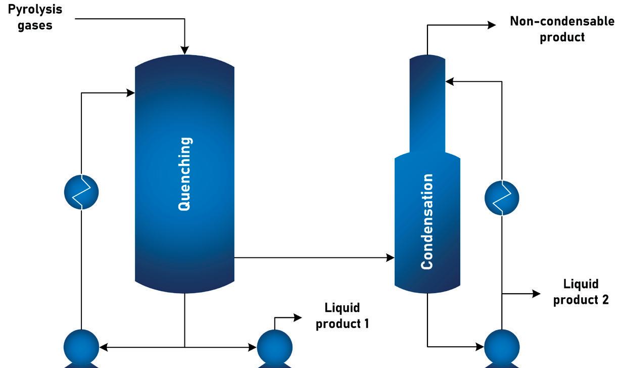
A new approach to quenching
To overcome the above-mentioned drawbacks of traditional quenching systems, Sulzer developed its proprietary PyroConTM quenching solution (see Figure 1). The technology employs thermal exchange systems that ensure precise temperature control and maximise hydrocarbon recovery. The rapid cooling, which takes place within seconds, is critical for maintaining the quality of the output while maximising the efficiency of the pyrolysis process. When compared to conventional quenching solutions, relying on standard heat exchangers, the design reduces the formation of secondary, light, and heavy by-products, which can otherwise hinder downstream processing. The design is enabled by column internals, which can handle challenging environments including high process temperatures, high gas loads, and high liquid load operation. The combination of different products made a reduction of the overall unit volume possible, leading to shortened residence times and more rapid temperature drops.
PyroCon integrates with existing pyrolysis setups and is scalable from pilot projects to industrial operations. Its modular design enables solutions for diverse process requirements, enhancing both operational flexibility and economic viability. The adaptability of this technology ensures that it can meet the specific demands of various feedstock types such as biomass or plastics, and processing conditions ranging from polymers like polyolefins (PP/PE) and polystyrene (PS), to biomass waste and
Figure 1. Exemplary configuration of Sulzer’s PyroConTM technology.
other materials. The technology can be integrated with downstream technologies, such as distillation units or hydrotreating technology, to produce high-quality outputs, contributing to a circular economy and enabling a more sustainable future. It offers a number of benefits, including:
Reduced downtime – longer operating cycles with minimum interruption for fouling maintenance
The technology features a fouling resistant design as the condensation takes place on liquid surfaces. A unique liquid recirculation design prevents the build-up of oligomers, waxes, or solids. Additionally, separation mechanisms ensure that hydrocarbons are efficiently segregated from non-condensable gases, maximising the economic output of pyrolysis processes. This technology can be configured for single-stage or multi-stage processes to separate products like waxes, oligomers, or solids formed in the pyrolysis unit.
Higher yields – optimal breakdown of feedstocks
The technology is engineered with a compact design that minimises internal volume, enabling rapid quenching of the processed material. This ensures precise temperature control, reducing unwanted secondary reactions and preserving product integrity. The system’s cooling mechanism condenses pyrolysis vapours within seconds, halting further breakdown and preventing the formation of larger, less valuable hydrocarbons. This rapid quenching leads to increased liquid yields, enhancing the efficiency of the recycling process and improving overall product quality.
Reduced costs through compact design, standard steel grades, and heat integration
The technology’s unique design ensures that the heat transfer surfaces of the condensing unit are always covered in liquid, preventing solid build-up and direct contact between hot gaseous products and the unit’s shell. This allows the use of standard stainless-steel grades, reducing the need for costly high-temperature and corrosion-resistant materials. The system’s reduced volume further lowers the material costs by requiring fewer construction materials and enables a compact footprint – ideal for space-constrained installations and modular process setups. On the operational side, the technology should facilitate energy efficiency through heat recovery. Circulating hot media streams can be leveraged to generate secondary utility streams, such as steam or heated thermal oil. This recovered energy can then be reused within upstream or downstream processing units, significantly lowering overall energy consumption. This integration can reduce the investment in equipment beyond battery limits, making it a cost-effective solution for pyrolysis applications.
Case studies
Single stage system for Carboliq
Sulzer Chemtech was requested by Carboliq, a plastic pyrolysis developer and operator in Germany, to provide a design for their condensation system.
A number of key design features needed to be implemented. Firstly, a full condensation system needed to be designed with high uptime. Not only is potential downtime of a continuous process detrimental for product yields but a lot of production time is also lost when blockages are removed from high temperature systems. With the proprietary fouling resistant design of PyroCon technology, Sulzer was able to meet these criteria whilst having been able to build a strong know-how of pyrolysis oils and their behaviours in their test facilities. This resulted in optimised vapour-liquid distribution and thermal control through dedicated column internals. The precise reaction control proved beneficial for product yields.
Secondly, only a small footprint was available to implement the system. Through Sulzer full scope capabilities, from process design through basic and detailed engineering and skid-mounted equipment supply, the system was optimised to accommodate the design restriction.
After Sulzer’s start-up support training, Carboliq’s operators were able to reliably operate the system.
Multi-stage design for Indaver
Indaver, a Belgium waste management company, implemented a 30 000 tpy polystyrene waste facility. After the thermal decomposition of polystyrene, re-polymerisation of the styrene monomers needs to be avoided. Thus, Indaver turned to Sulzer Chemtech to provide an adequate and cost-effective solution.
A multi-stage PyroCon was designed, supplied fully as skid mounted units that integrate seamlessly into the facility. Aside from the quenching technology, with integrated oligomer recovery and optimised heat integration, Sulzer’s scope included two distillation units all equipped with Sulzer’s proprietary internals. Before implementation, the design was tested in Sulzer’s pilot facilities in Switzerland, which allowed Sulzer to provide proven performance guarantees for the main product: styrene monomer to produce new plastics.
Conclusion
This article has introduced a significant technological advancement for the implementation of pyrolysis for biomass and plastics, addressing critical challenges while delivering economic and environmental benefits. By minimising downtime with a fouling resistant design, delivering higher product yields with precise reaction control, and reduced CAPEX using standard materials of construction, PyroCon offers quenching and separation solutions for sustainable polymer and biomass recycling.
As industries strive to meet ambitious sustainability targets and embrace circularity, Sulzer’s commitment in providing advanced technologies like PyroCon will be essential to unlock the full potential of plastics and bio-mass recycling, transforming waste into a resource and paving the way for a more sustainable future.
Dr Emmanuel Iro, Dr Richard Caulkin, and Sergio A. Robledo, UNICAT Catalyst Technologies, LLC, consider how catalysts can be revolutionised for the water gas shift reaction.
Extensive discussions have highlighted hydrogen’s pivotal role in the global energy mix. As a fuel, hydrogen emits virtually no pollutants, making it a highly appealing option for curbing greenhouse gas emissions and addressing climate change while providing the world’s growing population with sustainable access to future energy needs as a zero-emission fuel, power source, or energy storage solution, playing a pivotal role in powering the future. Producers are continually striving to enhance efficiency, become more environmentally friendly, and meet increasing production demands. Moreover, hydrogen is integral to numerous industrial processes that are essential for maintaining and enhancing quality of life.
Grey hydrogen, the most common type of hydrogen, is produced from natural gas through steam methane reforming (SMR). While SMR remains the predominant method for large scale hydrogen production, it relies on hydrocarbons as a feedstock and supplementary heating. This process emits substantial amounts of carbon dioxide (CO2), making it less sustainable. To achieve future targets and goals for a sustainable economy, it is crucial to operate SMR units efficiently and find ways to increase output without significant capital investment.
The water gas shift (WGS) reaction plays a vital role in this process by converting carbon monoxide (CO) into additional hydrogen, thus enhancing the overall yield of hydrogen production. The development of efficient and effective catalysts for the WGS reaction is, therefore, crucial for optimising hydrogen production.
This article will explore the importance of the WGS reaction, the challenges associated with traditional catalysts, and the features of the Magshift Textured Sphere catalyst. It will also discuss the potential applications and benefits of this new catalyst in industrial processes and its role in promoting a sustainable future.
Background on the WGS reaction
In the SMR process, methane (CH4) reacts with steam (H2O) to generate syngas, which is composed of hydrogen (H2), carbon monoxide, and a minor amount of carbon dioxide. The primary reaction is summarised as follows:
CH4 + H2O ⇌ CO + 3H2
While this reaction generates hydrogen, it also produces a significant amount of carbon monoxide, which is not desirable in the context of hydrogen production. To maximise hydrogen yield, the WGS reaction (WGSR) is employed. WGSR is an exothermic equilibrium chemical reaction where carbon monoxide reacts with water vapour (H2O, steam) to produce hydrogen and carbon dioxide. This reaction can be represented as:
CO + H2O ⇌ CO2 + H2 ΔH 298 °K = -41.4 kJ/mol
Being an equilibrium reaction, it means the reaction can shift either to the products or to the reactants, depending on several factors such as temperature, pressure, volume, molar ratio of the feed, and the presence of a catalyst.1
This secondary reaction effectively increases the total hydrogen yield by reacting the carbon monoxide – a by-product of the SMR reaction – with additional steam to generate more hydrogen. In doing so, it enhances the overall productivity and purity of hydrogen production, making it a vital component of the hydrogen economy. In ammonia synthesis plants, it is crucial not only to increase hydrogen production but also to remove carbon monoxide, as it acts as a poison to ammonia synthesis catalysts.2
Overview of existing catalysts
The development and optimisation of catalysts are crucial for enhancing the efficiency and effectiveness of various industrial processes. In the context of the WGS reaction, several types of catalysts are employed to facilitate the conversion of carbon monoxide and water into carbon dioxide and hydrogen. These catalysts include:
High-temperature shift (HTS) catalysts
HTS catalysts are typically composed of iron oxide with chromium oxide as a promoter. Chromium is added as a promoter to enhance thermal stability and resistance to deactivation, which are essential for the catalysts operating at temperatures between 310°C and 450°C (590°F to 842°F). While effective, they require high temperatures and can be prone to deactivation by sulfur compounds.
Medium-temperature shift (MTS) catalysts
These catalysts operate at intermediate temperatures, typically between 190°C and 330°C (374°F to 626°F). They often contain a mix of copper, zinc, and alumina. MTS catalysts aim to balance the high activity of LTS catalysts with the robustness of HTS catalysts. However, they still face challenges such as sensitivity to sulfur poisoning and maintaining stability over prolonged use. MTS catalysts are designed to bridge the gap between HTS and low-temperature shift (LTS) catalysts.
Low-temperature shift (LTS) catalysts
LTS catalysts are similar to MTS in composition, usually based on a copper-zinc oxide mix with small amount of alumina. The low temperature operations of these catalysts, which function
at lower temperatures (150°C to 250°C), distinguish them from the higher operation temperatures used for MTS operations. However, just like MTS catalysts, they are also prone to thermal sintering and remain vulnerable to poisoning by impurities such as sulfur. The upper temperature limit is thus set to prevent thermal sintering of the copper-based catalyst.
What sets different suppliers apart can be attributed to several factors, including the composition and structure of the catalysts. Additionally, the longevity and stability of a catalyst, along with its resistance to poisoning, are essential factors. Traditional catalysts used for MTS and LTS reactions are typically manufactured with a high loading of copper oxide and zinc oxide, balanced with alumina. The combined concentrations of copper and zinc oxides in the alumina matrix can reach as high as 80 - 90%. In these catalysts, copper and iron serve as the active materials for MTS/LTS and HTS WGSR respectively, while zinc, alumina, and occasionally chromium are incorporated as promoters. These promoters enhance the catalytic activity of copper or iron by electronically interacting with the copper oxide lattice structure, thereby boosting activity and mitigating copper or iron sintering.
Traditional catalysts are produced through methods such as extrusion or hydraulic pressing. Due to these manufacturing techniques, only mono-directional shapes can be created. Holes are incorporated to mitigate shape-related pressure drop issues and to introduce mathematically calculated geometric surface area. However, the benefit is limited. Firstly, the mono-directional shape and alignment of holes will not pack within a tube or vessel with optimal alignment to the process gas flow. Secondly, the process gas will always seek the path of least resistance.3 Most of the flow will preferentially seek out the voids between the shapes, thereby reducing the effective surface area available to the reactants.
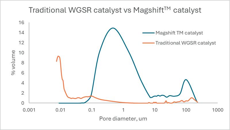
In addition, these manufacturing techniques, particularly tableting, lead to poor pore-size distribution, predominantly resulting in micropores. The presence of micropores causes diffusion resistance for the reactants, preventing them from effectively entering the catalyst pore system. Consequently, this leads to wasted catalyst surface area resulting in ‘low’ catalyst activity.
Initial catalyst development
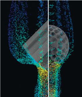
UNICAT’s Magcat Textured Sphere catalysts, applied in SMRs, are designed to improve heat transfer coefficient, provide high intrinsic strength, and lower pressure drop across the process. The textured surface of the catalyst creates a more turbulent gas flow, enhancing heat transfer and reducing tube skin temperatures (see Figure 1). This results in increased operational efficiency and extended tube life. These catalysts also feature optimised metal loading and placement, avoiding wastage and improving catalytic activity. These advancements contribute to higher hydrogen production and reduced energy costs.4
New catalyst development
Leveraging the carrier technology that was instrumental in the success of the Magcat Textured Spherical catalyst, UNICAT initiated the development of catalysts aimed at transforming the WGS market: Magshift. The new carrier has been specifically engineered with the WGSR in mind, featuring a
Figure 1. Flow simulation of gas passing over half a static textured spherical catalyst (gas moving from bottom to top) and half a ribbed cylinder showing the flow differences.
distinctly different carrier formulation compared to the original carrier. It has been designed to exhibit higher porosity with a specific pore size distribution. Although the casting technology remains the same, all the alumina components used are different. To accommodate the required higher pore volume, it was necessary to re-design the component formulation to maintain preferential physical support properties such as high strength and low brittleness.
Traditional LTS and MTS catalysts consist of copper oxide (CuO) dispersed on a mixed support matrix of zinc oxide (ZnO) and alumina (Al2O3). The ZnO not only supports the CuO but also inhibits copper crystallite sintering, thereby maintaining stable catalyst activity throughout the process. Similarly, alumina plays a crucial role in maintaining the dispersion of the active copper component, preventing sintering and enhancing thermal stability. Furthermore, alumina contributes to the overall surface area of the catalyst, improving the dispersion and providing a greater area for impregnating the active copper crystals, thereby ensuring sustained catalyst activity.
As previously discussed, tableting results in a pore size distribution that biases towards micropore formation (Figure 2), thereby rendering a significant portion of the surface area and active CuO inaccessible due to diffusion limitations. Tableting is commonly employed to impart mechanical strength to the catalyst particle. Carrier formulation development was conducted specifically for the WGS textured sphere catalyst. Through experimental design, the precise alumina particle size distribution within the supports has been engineered to provide optimal physical and chemical properties tailored to the shift reaction. These include high calcined strength to enhance pellet mechanical integrity and hydrothermal stability, reduced pellet brittleness, improved BET surface area, and the necessary surface acidity. Furthermore, the shift catalyst carriers developed exhibit significantly higher mean pore volume compared to traditional shift catalysts. This pore volume has been designed within a specific size range to optimise the WGSR performance (Figure 2). The manufacturing method inherently produces a robust matrix without necessitating the compression of particles to achieve strength, thus incorporating meso- and macropores that facilitate the utilisation of the internal surface area.
Through research and development efforts, UNICAT synthesised the copper-alumina based textured sphere catalyst using a novel synthesis method. This method enables copper to strongly interact with the alumina support, thereby eliminating the need for zinc or chromium promoters in the finished catalyst, which would otherwise compete for valuable surface area with the Cu crystalline structure. This allows for better dispersed, smaller Cu crystals and enhanced resistance to thermal sintering. Additionally, the textured sphere shape reduces drag and enables reactants to contact a greater geometric surface area of the particle, thereby maintaining a closer approach to equilibrium (ATE) throughout the process. Moreover, the textured spheres can be created in sizes ranging from 14 mm to 32 mm for WGS reactors. Such sizes are not feasible with traditional WGSR catalysts, which are limited to 3 mm to 6 mm cylindrical pellets. Traditional WGS catalysts have over 90% microporous structures. If manufacturers increase pellet sizes beyond 6 mm to reduce pressure drop issues, the catalyst performance significantly deteriorates, as the reactant gases struggle to reach the active sites due to
diffusion limitation. Magshift has over 70% macropores, allowing reactant gases to easily access all active sites. Additionally, the large pore size network facilitates the quick dissipation of formed products and heat from exothermic reactions, reducing copper sintering and extending the catalyst’s life-time-on-stream.
LTS catalyst performance
UNICAT’s newly developed catalyst for LTS operation consists of CuO on an alumina carrier. In testing conducted at its pilot plant facilities in Dewsbury, UK, the catalyst demonstrated performance comparable to that of commercially available catalysts. All the catalysts were first heated under nitrogen flow at 200°C for two hours to remove moisture. After the drying stage, hydrogen was introduced for catalyst reduction, under controlled conditions at 200°C for four hours. Subsequently, a feed comprising 10% CO in a carrier gas was introduced at a rate of 220 ml/min along with 0.5 ml/min of water over 90 ml of catalyst in an electrically heated reactor and maintained at 200°C. The hydrogen yields and CO2 yields were consistent with those of competitive products. Except for Traditional Catalyst 4, which exhibited lower catalytic activity (52 - 85% conversion), the other Traditional catalysts 1 - 3 demonstrated catalytic activity similar to the textured sphere catalyst (91 - 100% conversion) (Figure 3). This indicates that even with only 16% CuO, the new catalyst is comparable with the most active LTS catalysts tested.
Figure 2. Comparing the pore sizes and pore volumes of traditional WGSR catalysts with MagshiftTM
Figure 3. Low-temperature shift (LTS) reaction comparing Magshift LTS catalyst with traditional WGSR catalysts.
MTS catalyst performance
The newly developed catalyst for MTS operation exhibited similar performance characteristics. Like the new LTS catalyst, the formulation of the new MTS catalyst does not contain ZnO.
In testing conducted at the same pilot plant facilities in Dewsbury, the catalyst demonstrated performance comparable to that of commercially available catalysts. All the catalysts were first heated under nitrogen flow at 200°C for two hours to remove moisture. After the drying stage, hydrogen was introduced for catalyst reduction, under controlled conditions at 200°C for four hours. Subsequently, a feed comprising 20% CO in a carrier gas was introduced at a rate of 220 ml/min along with 0.88 ml/min of water over 90 ml of catalyst in an electrically heated reactor and maintained at 300°C.
The hydrogen yields and CO2 yields were consistent with those of competitive products. Under MTS test conditions, the Textured Sphere catalyst exhibited slightly higher activity than the other catalysts (Traditional Catalysts 2 - 4), consistently achieving 100% conversion throughout the test duration (Figure 4). Traditional Catalysts 2 - 4 also demonstrated
Figure 4. Medium-temperature shift (MTS) reaction comparing Magshift MTS catalyst with traditional WGSR catalysts.
high activity, achieving 97 - 98% conversion. However, Traditional Catalyst 1 performed poorly at the elevated MTS test temperature of 300°C, with conversion rates ranging from 0.8% to 1.4%. This suboptimal performance could be attributed to the sintering of copper oxide in Traditional Catalyst 1 under these conditions.
These results are noteworthy, given that Magshift LTS and Magshift MTS lack ZnO and contain only a fraction of the CuO found in traditional catalysts. Additionally, the advantages supplied by the textured sphere shape are diminished in the pilot plant due to suboptimal flow dynamics. However, based on the performance observed in the pilot plant, industrial scale performance is anticipated to be superior. This expectation is in line with what UNICAT observed when Magcat was implemented at an industrial level.
Discrete element modelling
Discrete element modelling of traditional WGSR and textured sphere catalyst packings, coupled with computational fluid dynamics modelling, confirmed that the textured sphere catalyst demonstrated improved global and local bed voidages, with associated uniform flow channels. These features contribute to the efficient flow of reactant gases and product streams, as well as better temperature distribution and reduced pressure drop values through the packed reactor beds (Figure 5).
Summary
In summary, the WGS reaction is a critical process for enhancing hydrogen production and reducing car¡de emissions in various industrial applications. Traditional WGS catalysts, while effective, face challenges such as temperature sensitivity, susceptibility to poisoning, and diffusion limitations due to their manufacturing methods, resulting in wasted surface area and active metal area. UNICAT’s new line of catalysts addresses these challenges through its innovative textured sphere design and unique carrier technology, featuring a tailored pore size distribution that optimises the accessibility of active sites. By eliminating the need for zinc or chromium promoters and providing enhanced mechanical strength and hydrothermal stability, the Magshift technology offers comparable or improved performance in both LTS and MTS applications. The larger macropore structure facilitates quick product and heat dissipation, extending catalyst life and improving efficiency. Pilot plant testing confirms that the new catalyst achieves high conversion rates, positioning it as a promising solution for optimising hydrogen production and advancing a more sustainable energy future.
Figure 5. Graph outlining the effect of catalyst shape and size on pressure drop and a middle (bulk) section of each loaded column from modelling was extracted for visual representation, left to right, Traditional WGSR (5.3 x 5.0 mm) catalyst vs Magshift (14 mm).
References
1. BARAJ, E., CIAHOTNEÝ, K. and HLINČÍK, T., ‘The water gas shift reaction: Catalysts and reaction mechanism’, Fuel, 288, p. 119817, (2021).
2. PALMA, V., RUOCCO, C., MARTINO, M., MELONI, E. and RICCA, A., ‘Catalysts for conversion of synthesis gas’, Bioenergy systems for the future (pp. 217 - 277), Woodhead Publishing, (2017).
3. STUCKLEY, M., ‘A step change in catalyst development’, Hydrocarbon Engineering Whitepaper: Catalyst Evolution, (2023).
4. STUCKLEY, M., ‘A step change in catalyst development’, Hydrocarbon Engineering, (March 2023), pp. 73 - 78.
A podcast series for professionals in the downstream refining, petrochemical and gas processing industries
LISTEN NOW
EPISODE 1
Alan Gelder, Senior Vice President of Refining, Chemicals and Oil Markets at Wood Mackenzie, provides a review of downstream markets in 2024 and looks ahead to what 2025 may hold for the sector.
EPISODE 2
Dr Klaus Brun, Global Director of Research & Development, Ebara Elliott Energy, discusses the progress that is being made towards adapting centrifugal compressors for high-speed hydrogen compression.
EPISODE 4
Rasmus Rubycz, Market Manager for New Energy at Atlas Copco Gas and Process, considers how heat pumps as an industrial technology are gaining greater attention as a result of the increased drive for sustainability and the challenges and opportunities of electrification of process heat.
EPISODE 3
Peter Davidson, CEO of the Tank Storage Association (TSA), outlines the essential role that the tank storage sector has to play in ensuring supply security and resilience, as well as in facilitating the energy transition.
Sponsored by
EPISODE 5
Mike Logue, Owens Corning Business Director – Specialty Insulation, delves into factors that can support the performance, safety and longevity of insulating systems installed in hydrocarbon processing environments, including cryogenic facilities.
EPISODE 6
Leakhena Swett, President, ILTA, and Jay Cruz, Senior Director of Government Affairs and Communications, ILTA, consider the importance of trade associations and industry collaborations.
As hydrogen emerges as a key vector in the global energy transition, its efficient and cost-effective production has become increasingly critical. Steam methane reforming (SMR) remains the predominant method for producing hydrogen, supplying major industries such as the refining, chemical, and fertilizer industries. However, growing hydrogen demand places pressure on SMR facilities to boost production without increasing
Ken Chlapik, Johnson Matthey, explores how to meet the challenge of efficient hydrogen production with higher efficiency catalyst solutions.
environmental impact or operational costs. Solutions like the CATACEL SSRTM reactor technology have been developed to address these challenges.
The rising demand for hydrogen production
The growing role of hydrogen in decarbonisation efforts is clear. It is a versatile energy carrier, supporting applications
ranging from fuel cells to synthetic fuels and heavy industry. Global hydrogen demand has more than tripled since 1975, driven largely by industrial processes, and is expected to continue rising as governments and companies set ambitious net zero targets.
Existing SMR facilities often operate at or near capacity, making it difficult to meet this rising demand, and operators face multiple technical and operational constraints. For instance, increasing throughput can exacerbate thermal stress, pushing tube wall temperatures close to material limits, which risks reducing their lifespan. Similarly, conventional ceramic pellet catalysts, while effective, can result in high pressure drops and inefficient heat transfer. The combined effect is a ceiling on production capacity and an increase in the carbon intensity of hydrogen.
In response, operators are seeking cost-effective and sustainable methods to enhance SMR performance without requiring significant capital expenditure or additional energy inputs. This is where structured catalysts can help.
The role of structured catalysts
Structured catalyst technology offers a practical solution to many of the challenges faced by SMR operators. Unlike conventional ceramic pellets, which rely on bulk material designs, they employ engineered geometries that optimise
flow, heat transfer, and catalytic activity. Johnson Matthey’s CATACEL SSR technology has been implemented in over 17 SMR facilities globally.
The technology breaks away from many of the limitations imposed in using ceramic pellets by adopting a foil-based structure. Through this design, it exhibits a higher activity, improved heat transfer, lower pressure drop, and improved resistance to carbon formation. These types of catalysts offer a path to increased efficiency and sustainability in hydrogen production.
It uses a special high temperature alloy as a substrate material. The alloy strip is formed into engineered foil structures called fans, which are coated with a nickel-based steam reforming catalyst using a proprietary process that ensures the catalyst remains attached to the surface of the foil during the catalyst lifetime. The fans are stacked one upon another in the reforming tube, separated by thin metal washers. The outer edges of the fans are located close to, but not touching, the internal surface of the tube (see Figure 1).
The stacked fans deliver excellent heat transfer by impinging gas on the internal surface of the reforming tube rather than relying on convective heat transfer mechanisms. During operation, gas flows down the tube and encounters the first fan structure. It cannot move through the fan and therefore it is forced out of the triangular ducts. The process gas jets directly onto the internal surface of the reformer tube, where it gathers heat. Having nowhere else to go, the gas flows around the edges of the fan and back into the triangular duct on the underside of the fan and the targeted flow of process gas ensures contact with the increased catalysts surface across the stacks compared to randomly packed pellets. The washers that separate the fans from one another facilitate this flow back into the fan. Once inside the fan, the gas is free to move to the next fan in the stack and repeat the process.
By designing the catalyst in this way, heat transfer is increased through a mechanism known as impingement. Process gases are forced directly against the internal tube walls, which disrupts the insulating gas layer typically found in conventional systems. This direct interaction enhances the efficiency of heat exchange, improving heat transfer by 20 - 30% compared to traditional pellet systems.
Production benefits
These structural advantages translate directly into measurable production benefits, including increased hydrogen output and reduced energy consumption. For instance, at a major US Midwest refinery, the enhanced energy management, superior methane conversion rates, and optimised heat transfer within the reformer provided by the CATACEL SSR reactor has delivered a 15% increase in hydrogen production without
Figure 1. CATACEL SSR fan structure.
Figure 2. Comparison of hydrogen production using a standard pellet and CATACEL SSR technology.
OFTEN IMITATED, NEVER DUPLICATED
Pop-A-Plug® Tube Plugs
ASME PCC-2 Compliant Heat Exchanger Tube Plugging System
Trusted by power and process plants around the world as their go-to tube leak solution, Pop-A-Plug Tube Plugs from Curtiss-Wright are engineered for optimal performance throughout the life cycle of heat exchanger equipment. Controlled hydraulic installation eliminates welding and time-consuming pre-/post-weld heat treatments that can cause damage to tubes, tube sheet ligaments and joints.
• Simple hydraulic installation − no welding!
• Helium leak tight seal to 1x10 -10 cc/sec
• 100% Lot tested to ensure unmatched quality
• Pressure ratings to 7000 PsiG (483 BarG)
• Wide range of sizes and ASME/ASTM certified materials available
Ask about our Smart Ram 640T for fast & reliable cordless installations!
877.383.1029 l est-sales@curtisswright.com l cw-estgroup.com/HydroEng25
additional natural gas consumption. Such improvements are particularly valuable for plants operating near their design limits, where conventional upgrades would require substantial investment.
In addition, structured catalysts can reduce pressure drop due to their high voidage design. Lower resistance to gas flow enables operators to maintain or increase throughput without requiring additional energy to overcome flow constraints. The increased geometric surface area of structured catalysts ensures more effective contact between the gas and catalytic material, promoting better methane conversion and reducing methane slip. Figure 2 shows how CATACEL SSR can provide increased hydrogen production at the same SMR firing duty or a reduction in firing duty for the same level of hydrogen production.
The effectiveness of the reactor is supported by a decade of commercial data. This catalyst has demonstrated consistent performance across a range of SMR applications. Long-term reliability is critical for operators seeking proven technologies to enhance their operations.
The environmental benefits of advanced catalysts align closely with global sustainability objectives. By improving the efficiency of heat transfer and methane conversion, these systems reduce the amount of natural gas required to produce hydrogen. This translates to lower CO2 emissions, directly contributing to decarbonisation efforts.
At the Slovnaft refinery in Slovakia, the adoption of the CATACEL SSR technology facilitated a significant increase in throughput while maintaining lower tube wall temperatures. Data from this installation suggests that the CATACEL SSR reactor has enabled natural gas savings of more than 8000 t over the lifecycle. These savings are accompanied by a 15% reduction in SMR furnace CO2 emissions, providing a dual benefit of cost reduction and environmental impact mitigation. This example highlights the ability of structured catalysts to increase production efficiency. Their use balances energy consumption during significant uprates, thereby reducing the energy required per unit of hydrogen.
Addressing sustainability goals
As the demand for lower-carbon fuels grows, many refineries and biofuel producers are incorporating biogenic feedstocks into their processes. These feedstocks, which often have a lower hydrogen content than fossil-derived alternatives, require additional hydrogen during upgrading. By utilising hydrogen-lean biogenic feeds, producers can significantly reduce the overall carbon intensity of fuels, contributing to lower Scope 3 emissions across the value chain. Many of these projects are designed in phases, allowing existing hydrogen production facilities to establish an uprate at existing plants and supply the incremental hydrogen needed, minimising capital investment and operational disruptions. This approach supports a more sustainable and cost-effective transition to low-carbon fuel production while optimising existing assets. Moreover, the design of the structured catalyst minimises the risk of carbon formation, a common issue in conventional SMR systems. Lower steam-to-carbon ratios can be maintained without compromising performance, further enhancing the sustainability of hydrogen production.
Evidenced lifecycle performance and reliability
Durability and consistency are critical for any catalyst technology, and structured systems excel in these areas. The CATACEL SSR technology has been deployed in commercial settings for over a decade with some installations maintaining their efficacy for more than nine years. This robustness ensures operators benefit from long-term reliability and minimises the frequency of catalyst replacement, reducing both costs and disruptions.
The structured design also offers practical advantages during installation and maintenance. Preassembled stacks of catalyst-coated foils can be easily deployed using standardised installation tools, simplifying the process and minimising downtime. Installation and extraction of the catalyst is executed in the same time period as a typical pelleted catalyst changeout. This ease of use, combined with the proven operational benefits, makes structured catalysts an attractive option for both new installations and retrofits.
The financial advantages of structured catalysts further enhance their appeal. By enabling significant capacity gains without requiring costly plant modifications, these systems provide a cost-effective alternative to mechanical upgrades. For medium-to-large hydrogen plants, the net present value (NPV) of adopting structured catalysts can reach US$25 - 50 million over a 10-year period, driven by natural gas savings, increased hydrogen output, and avoided capital expenditure.
The combination of lower operating costs, enhanced efficiency, and reduced environmental impact positions structured catalysts as a valuable investment for SMR operators.
The success of solutions such as the CATACEL SSR technology is rooted in the extensive experience and expertise of their developers. Johnson Matthey has been at the forefront of catalyst technology for over 70 years, with deep experience in reforming processes and industrial scale catalyst coating. This knowledge has informed the design and implementation of structured catalysts, ensuring they meet the complex needs of SMR facilities.
Conclusion
As hydrogen demand continues to grow, technologies that enable efficient and sustainable production are essential. Structured catalyst systems offer a practical and effective means of addressing the challenges faced by SMR operators. By increasing hydrogen output without additional energy input or capital expenditure, lowering CO2 emissions and carbon intensity of the hydrogen while also improving furnace efficiency with a lower steam-to-carbon ratio, these systems support both economic and environmental objectives.
With a decade of proven performance and extensive field validation, the CATACEL SSR technology is a useful innovation for the pursuit of efficient, low-carbon hydrogen production. The technology combines technical, operational, and sustainability benefits, proven by real-world performance data, positioning this solution as a tool for the evolving hydrogen economy.
WWW.ZWICK-ARMATUREN.DE
Stefan Roeder and Tim Busse, Evonik Catalysts, examine how catalysts facilitate cleaner production of vinyl chloride monomer (VCM).
Demand for polyvinyl chloride (PVC) continues to grow; as of 2022, global demand exceeded 48 million t, and its global market size is forecast to grow to nearly 60 million t by end of this decade (S&P Global, Chemical Economics Handbook 2024).1 Although production capacity has risen globally by 5.8% per year, some countries have seen an annual rise of more than 10% since 2005. It is no surprise, given PVC’s diverse applications, including in construction (window frames, flooring, pipes), automobiles (interior upholstery, airbag covers, bumper guards), and medical products (blood bags, tubing, catheters).
As with any polymer, it cannot exist without the monomer. Therefore, vinyl chloride monomer (VCM) is the building block of PVC. More than 99% of worldwide VCM production is consumed for PVC production. Between 2017 and 2022, the global VCM capacity grew at 2.4% annually. According to S&P Global, capacity increased from 53 million t to over 60 million t; by 2027, it is projected to reach about 68 million t, an average annual growth of 2.6%.2
However, when talking about the growth of PVC and VCM it would be remiss not to address the so-called ‘elephant’ in the production process. The by-products of VCM production – more specifically, acetylene (C2H2) – will, in turn, form chlorinated by-products that are costly to remove and to discard. The good news is that a more economically and environmentally friendly approach to VCM production and, in turn, the PVC process, is possible.
A combination of hydrogenation technology and fixed-bed catalysts can lead to avoidance of formation of the undesired by-products while returning valuable raw materials to the process. Furthermore, utilising a catalyst which contains a smaller amount of precious metals can also translate to lower investment costs for producers, and a reduced environmental impact.
Production and by-products
To understand the impact of hydrogenation technology, it is important to outline the steps throughout the VCM process (Figure 1) – beginning with ethylene (C2H4), a crucial feedstock in the production of various chemicals.
With ethylene and chlorine together in a reactor, the intermediate compound ethylene dichloride (EDC) is produced. EDC must then be purified before it undergoes pyrolysis, where it is thermally cracked to produce VCM. Lastly, there is the purification and separation of VCM. Distillation columns are used to separate VCM from EDC, hydrogen chloride (HCl), and remaining by-products.
Although this process yields high product output, it is also where trace amounts of acetylene and other undesirable by-products are generated. If acetylene is returned to the process in the HCl recycling stream, it creates a significant amount of undesired chlorinated by-products in the oxychlorination reactor – which is why selective acetylene hydrogenation (Figure 1, A) is so important.
The impact of hydrogenation technology
The majority of acetylene removal is managed by the effective method of selective hydrogenation; it is considered to be an economically and environmentally friendly approach. With hydrogenation, producers can prevent approximately 860 t of toxic chlorinated byproducts in a 300 000 tpy production of VCM.
Moreover, return on investment can be as little as two years when introducing such a technology. This is because the process is circular and has an immediate effect from when catalysts are introduced, ensuring the undesired by-products are eliminated from the production process.
When it comes to selecting a catalyst, a noble metal palladium (Pd) catalyst is commonly used. Numerous empirical studies show that Pd is the most suitable precious metal for both activity and selectivity when choosing the most active component in the hydrogenation of acetylene. In comparison to other precious metals, it boasts the major benefit of being able to adsorb large amounts of hydrogen. A suitable support material for the active Pd must be selected carefully, with a very non-porous acid resistant silicone dioxide (SiO2) granulate with low BET surface area being the most promising option.
With a suitable hydrogenation catalyst like this, acetylene conversion rates of more than 98% can be achieved. Other benefits include increased EDC purity and reduced fouling rates of the EDC cracking furnace. Additionally, the formation of unwelcome chlorinated hydrocarbon is limited by a catalyst, resulting in a lower cost for the separation and disposal of these by-products.
By returning ethylene as a raw material that can go through the process again, the side product acetylene is recycled back to VCM – not only improving efficiency, but also the quality of the
Evonik‘s catalyst toolbox for VCM recycle-stream polishing enables boosting your
resulting PVC in the long-term. Additionally, it means less ethylene needs to be purchased for future VCM production processes, due to the increased yield of the process. As such, this results in higher added value in resource-conserving and environmentally friendly VCM production.
Complementary to this hydrogenation process is benzene chlorination (Figure 1, B). In the synthesis of VCM, an additional recycle stream can be enabled using a benzene chlorination catalyst. Recycled EDC (boiling point 84˚C) and benzene (81˚C) are difficult to split through distillation, in turn leading to high fouling rates in the EDC cracker. By utilising a catalyst such as Aerolyst® BC281 in a trickle bed operation for benzene chlorination, monochlorobenzene is generated, which boils at 123˚C and can easily be split from EDC.
Case study: delivering cost savings
Evonik, a pioneer for the catalytic hydrogenation stage in the production of VCM, has developed catalysts in co-operation with Vinnolit GmbH & Co. KG. since the 1970s. The proprietary Noblyst® E39 catalysts are tailored to the hydrogenation process, tested, and used in Vinnolit’s commercial plants. It is a high-performance palladium on silica catalyst that offers improved chemical reactivity and ethylene selectivity. It also has a long catalyst lifetime. The series was designed specifically for the selective hydrogenation of acetylene-to-ethylene within the VCM production process, improving ethane dichloride selectivity and minimising byproduct formation in the oxychlorination step.
By reduction of by-product formation, Noblyst® E39 series increases the
Implementing the hydrogenation unit and avoiding acetylene reaching the oxychlorination reactor prevents chlorinated byproduct formation. Acetylene, if not reacted, is chlorinated to low boiling compounds like di- or tri-chloroethane and high boilers like tetrachloroethane and tetrachloroethene. In addition, polymerisation of acetylene and ethylene, or acetylene and acetylene, including chlorination, would take place – causing chlorinated tar formation. By reducing said formation, the EDC quality increases substantially (Figure 2), with an increase in EDC yield of about 0.3% – based on 300 000 tpy, this increase equates to 900 t of target product. From this, it can be concluded that producers using a hydrogenation reactor can potentially save significant operational and capital expenditure costs.
Opportunities for improving environmental impact
Currently, the typical process for VCM production and selective acetylene hydrogenation requires significant amounts of palladium. In a typical 300 000 tpy VCM plant, 12 kg of palladium instalment is required in the
process.
Figure 1. The VCM process, and Evonik’s catalysts for recycle stream polishing.
Figure 2. The benefits of Noblyst® E39 series.
Our business is the “insides” of distillation and absorption columns …
Whether you are designing a new column or revamping an existing design, let our decades of experience and expertise assist you in making and implementing the most appropriate solution, at minimum cost, not only to achieve the desired throughput but also to accommodate feed rate variations and minimise downtime.
Some day all trays will be made like this …
For trayed columns, we design and manufacture all type of trays including but not limited to:
Bubble Cap Trays Slotted & Un-slotted Caps 2” to 6”nb Sieve Trays
Valve Trays Floating Valves - Round
Valve Trays Floating Valves - Rectangular
Trays Fixed Valves
Proprietary Trays S-Wave Ripple
Trays
From receipt of your enquiry, our team of dedicated professionals are ready to give you a fast, efficient, knowledgeable and friendly response. At DtEC, we all believe the customer comes first.
Distillation Equipment Company Ltd, The Boat Yard, Newcastle Road, Stone, Staffordshire ST15 8JZ, United Kingdom Tel: 0044 1785 602810
Fax: 0044 1785 602811
Looking at the palladium supply chain, just under three-quarters (73%) is dependent on primary sources, the main producers of which are South Africa (29%) and Russia (44%). Securing palladium from a secondary source can help safeguard against supply disruption, which is particularly important in light of geopolitical events such as the Russia-Ukraine conflict.
Conclusion
Primarily driven by the rising demand from the global construction sector – the largest consumer of PVC – VCM production is also influenced by urbanisation and infrastructure development; it also creates value to human life, seen in essential applications such as blood bags and other medical necessities.
On Demand Webinars
On Demand Webinars
On Demand Webinars
Explore our library of free-to-access On Demand Webinars, covering a range of topics in the downstream sector covering a range of topics in the downstream sector
Explore our library of free-to-access On Demand Webinars, covering a range of topics in the downstream sector
Visit: www.hydrocarbonengineering.com/webinars
On Demand Webinars, covering a range of topics in the downstream sector Visit: www.hydrocarbonengineering.com/webinars
www.hydrocarbonengineering.com/webinars
Victor Scalco, General Atomics Electromagnetic Systems, and Clifford Avery, Ketjen, discuss efficient separation technologies for a sustainable refining and petrochemical industry.
As global demand for energy continues to surge, the refining sector is confronted with the dual challenge of meeting escalating demand while simultaneously reducing carbon emissions. This article proposes a comprehensive strategy to retrofit or upgrade existing complex refineries utilising fluidised catalytic cracking (FCC) and resid fluidised catalytic cracking (RFCC) units. Increased emissions and energy loss are a reality when driving the FCC units at a high severity to produce propylene for petrochemical production. Refiners are
actively developing new solutions to decarbonise this process and the finished products, such as transportation fuels or commodity chemicals, as part of this energy transition. As a result, refiners are now exploring the co-feeding of alternative feedstocks, including renewable and recyclable oils, as a means of lowering the carbon footprint of their final products. Given its inherent flexibility, the FCC process has potential to lower the carbon intensity in this effort. However, these new feeds still present challenges, such as additional contaminants, instability and
miscibility issues, and elevated acidity that can lead to a variety of operational challenges in an FCC unit. 1 On the path to achieve carbon neutrality, it is expected that global demand for crude oil-based gasoline and diesel will significantly decline, thus forcing most refineries to shift to producing more petrochemicals, including liquid renewables, to remain profitable while maintaining the focus on decarbonisation. This article will discuss several challenges in the path to decarbonisation shifting away from transportation fuels within increased propylene demand by means of the FCC unit process. 1,2
Improving efficiency to optimise yields
Upgrading the FCC unit can significantly enhance the integration of petrochemical processes within refineries. The unit primarily converts heavy petroleum feedstocks into lighter, more valuable products like gasoline and diesel. However, by implementing specific upgrades, refineries can optimise the FCC unit to produce higher yields of petrochemical feedstocks, improving overall operational efficiency and profitability. Implementing advanced process control systems can optimise the FCC unit’s performance in real-time. These systems can adjust parameters dynamically based on feedstock variations, desired product specifications, and product economics, minimising waste as a result to support the refineries’ net zero goal. Benefits can also be found by upgrading heat exchangers and integrating heat recovery systems not only to recover heat energy losses but to improve FCC unit energy efficiency. By capturing and reusing heat generated during the cracking process, refineries can reduce overall energy consumption and enhance the economic viability of producing petrochemical products. 3
Another option in support of decarbonisation and increasing profits from the production of propylene is through catalyst selection. Choosing advanced catalysts that are more selective towards lighter olefins, such as propylene and ethylene, can significantly increase the output of petrochemical precursors while concentrating on the reduction of emissions. Maximising catalyst accessibility, which is a measure of how easily heavy oil molecules can navigate the catalyst pore structure to find active cracking sites, will result in improved primary products such as improved LPG olefinicity, increased gasoline selectivity, and increased light cycle oil (LCO)/ slurry ratio. Reducing the rare earth on zeolite (REO/Z) will result in less hydrogen transfer and increase gasoline octanes and LPG olefinicity; however, simply reducing the REO/Z without extensive knowledge of the FCC operations and catalyst system is not wise. A thorough understanding of the FCC regenerator severity and underlying catalyst systems incorporated when designing the optimum REO/Z is required. A well-designed active matrix can reduce undesired products like slurry and improve primary products mentioned earlier.
Mobil invented the ZSM-5 zeolite in the 1960s to increase conversion. ZSM-5 is a shape selective zeolite, known to centre crack gasoline olefins to desired petrochemical products such as propylene, butylene, and at times, ethylene. Catalyst companies, like Ketjen, have
incorporated ZSM-5 into FCC catalyst since the early 1980s.4 Since then they have been able to improve the use of ZSM-5, other shape selective zeolites, and FCC catalyst synergies in support of petrochemical production. Catalyst families were developed to maximise propylene in support of increased efficiency and the reduction of losses. These shape selective zeolites are now a common component for maximising petrochemical precursor feedstocks in the refining industry. Focusing on catalyst alone is not complete without looking at the FCC optimisation and riser efficiency.
Modifying the FCC unit’s riser section allows for better catalyst distribution and contact time with the feedstock. A design that promotes turbulent flow can enhance catalyst effectiveness by improving the distribution of catalyst within the unit. Modern maximum propylene riser termination devices can either increase residence time or increase catalyst to oil ratio (cat/oil) to increase reaction severity. The implementation of a secondary or dedicated riser to crack recycled light naphtha or light hydrocarbons in general can play a fundamental role in maximising light olefins yield, especially in the range of ethylene and propylene under severe reaction conditions. Additionally, upgrading to advanced feed injection systems ensures uniform dispersion, optimum atomisation, reduced hydrocarbon partial pressure, and optimal contact between feed and catalyst.2
Simple adjustments can be accomplished without the addition of expensive upgrades or catalyst trials. Adjusting operating conditions such as cracking temperature, pressure, and feedstock composition can help in maximising desired olefins production. Increasing the severity of the cracking process can lead to higher yields of lighter products but requires careful balancing to avoid excessive coke formation and catalyst deactivation. Maximising riser outlet temperature (ROT) is one of the first independent process variables to consider due to the relative ease and flexibility to change. Most FCCs will operate in the region of 520 - 530˚C for maximum gasoline output. Increasing the ROT will increase LPG olefin production. For maximum LPG olefins, high severity FCCs can operate >540˚C. More extreme process conditions can be applied when the FCC unit is upgraded to ‘high severity’ or maximum propylene FCC where they can operate above 560˚C with reduced hydrocarbon partial pressure (>7 wt% dispersion seam), and cat/oils exceeding 15 wt/wt in some cases.4
Investment in these new FCC technologies is an excellent prospect for olefins optimisation. Advancements like the HS-FCC unit is actually a downer (not a riser) with contact times <1 second and even more elevated cat/oil ratios. These improvements to the well-known FCC process can reach a considerably higher level of light olefins production, in particular propylene, to bridge the gap between refining and petrochemicals industries. 5
By focusing on these upgrade strategies, refineries will not only boost their FCC unit’s efficiency but also enhance their capability to produce a broader range of valuable petrochemical products, aligning with market
demands and economic trends. Investing in existing equipment is well within the framework of reaching net zero. The cost of upgrades to the FCC or new catalyst trials to enhance process conditions and optimise the unit’s severity is offset by better yields. On average these yields can provide greater than US$15 million of additional revenue annually while supporting decarbonisation in the refinery.
Slurry oil yields and properties
As might be expected, slurry oil quality is a function of such variables as the properties of the FCC feed, severity of the operation, type of catalyst, operating conditions in the FCCU, etc. The marketability of slurry is penalised on its density, clarity, and contaminate contents. Slurry oil yields ranging from 1 - 2 vol.% for easy to crack feeds to as much as 24 vol.% on RFCC feeds or maximum diesel applications have been observed. Upgrading slurry oil is problematic due to its low API gravity and high content of asphaltenes in resid operations. Properties of typical slurry oils can be found in Table 1.
Resid (>1050˚F) in general and asphaltenes in particular are large hydrocarbons with a high carbon to hydrogen ratio. Resids have a molecular size of >25 Å and asphaltenes have a molecular size of >100Å. These compounds are especially rich in metals and contain nickel and vanadium which promote coke generation when deposited on FCC catalysts. When cracking residual feedstocks, the zeolite pores (<14 Å, 7.4 Å through the super cages) are not large enough to crack these large asphaltene structures to enter the pores of the catalyst and therefore pass along to the slurry. A well designed RFCC catalyst will contain an active matrix with meso pores (100 - 500 Å) to increase the cracking of these large hydrocarbon compounds. The level of conversion of asphaltenes in an RFCC unit is then a function of the
API gravity -8 to 1 to 32
Sulfur (wt%) 0.5 to 1.3 to 5.8
Nitrogen (ppmw) 50 to 1600 to 10 100
Aromatics 31 to 53 to 96
Asphaltenes (vol%) Nil to ~8
Solids (ppmw) 1000 to 6000
Nickel (ppmw) 0 to 110
Vanadium (ppmw) 5 to 200
size
0 - 5
5 - 15
accessibility and the selectivity of the active matrix in the catalyst.3,7 Catalyst particles in the slurry, besides containing nickel and vanadium, can also bring in sodium and other feed metals that are deposited onto the catalyst. Slurry oil may also contain other solid FCC particles such as SOx reduction, CO promoter, fuel sulfur reduction, metals traps, and bottoms cracking additives. The elements in these additives (Mg, Pt, Pd, Ce, Ca, etc.) can change the quality of the slurry/sludge. As refiners introduce more and more resid into the FCC, slurry oil yields will increase and the quality of the slurry oil will decrease, in addition, a larger proportion of asphaltenes and heteroatoms will enter the FCC. This is relevant because the level of asphaltenes in the slurry oil becomes a factor in deciding which technology is best for removing particulate solids. Mechanical filtration becomes problematic in these scenarios due to the occlusion from asphaltenes and waxes presented in heavier resid feedstocks used to produce high levels of propylene in petrochemical development. This leaves most complex refineries looking for a more effective source of clarification and reliable fines removal system.7,8
Slurry oil particulate removal technologies
Holding tanks have been used to allow solids to settle out of the slurry oil. The resultant decanted oil solids content will be a function of the sedimentation tank design, the physical characteristics of the slurry, the temperature of the storage tank, and if settling aids are used. It should be noted that another product is being generated along with decanted/clarified oil, and that is sludge. In most cases, this sludge is recycled back to the riser. Slurry oil holding tank sludge has been classified as a hazardous waste and therefore requires special treatment and expense for its disposal. Depending on the tank size and rate of slurry oil production, costs can be millions of dollars per cleaning. In the absence of countermeasures, increasing resid feed to the FCC will tend to increase the rate of slurry oil production and sludge formation rate. 3
Mechanical filtration, first put into slurry oil service around 1990, operates at temperatures up to 315˚C and employs tubular porous metal elements. The solids collect on the inside of the elements while the filtrate passes through to the outside. Some filters use porous sintered woven wire mesh metal filters and operate at 232 - 343˚C. While others employ a 2 - 5 µ m woven wire filter element, using LCO as a backwash at 176˚C, and claim 85 - 95% solids removal from the feed slurry. 9
Electrostatic separation of FCC catalyst fines from slurry oil has been in commercial operation for over 30 years. Electrostatic separation uses a charge causing the catalyst particles to become trapped in beds of glass beads while maintaining flow without significant pressure drop. In this way, electrostatic separators have been able to remove over 97% of the catalyst present in slurry oils. As the concentration of vacuum tower bottoms in FCC feeds grows, modern techniques used for selection of catalyst removal from slurry oil will increasingly favour
Table 1. Properties of typical slurry oils
Table 2. Typical particle
distribution in slurry oils
POWERFUL CHEMISTRY, UNPARALLELED EXPERTISE
KETJEN’S INDUSTRY LEADING CATALYSTS UNLEASH THE POWER OF ADVANCED CHEMISTRY THROUGH:
INVESTMENTS to meet future production supply demands.
INNOVATIONS that expand profitability and efficiency, while lowering costs.
INSIGHTS, based on customer interactions and market factors, allowing for rapid response to industry needs.
Learn more at KETJEN.COM
Table 3. Typical permissible solids contents for various slurry oil product applications
Market Clarified slurry oil (solids, ppm)
Carbon black feedstock
Refinery use, fuel or coker feed
Marine fuel, #6
Pitch feedstock
Needle/anode coke feedstock
50 - 500
50 - 150
50 - 150
25 - 100
25 - 100
Hydroprocessing feedstock 10 - 50
Carbon fibre feedstock 5 - 10
electrostatic separation because it is inherently less likely to foul or coke due to increasing asphaltene levels in the slurry. Particle size distribution ranges from a variety of slurry oils are shown in Table 2. Note that for these slurry oils, over 90% of the particles range in size from 0 - 25 µ m. In comparison, this means that very large holding tanks and long holding times are required to meet higher value product specifications in decanting processes and smaller particles can pass through mechanical processes. 10
The bottom line
Achieving net zero will come at a cost, but optimising processes and utilising advanced technology will provide off-setting dividends in the bottom line of the refiner. Some of the value generated from an electrostatic separator in removing FCC catalyst fines from slurry oil can be illustrated using the following example. An 80 000 bpd gas oil FCC unit has a slurry oil yield of 4 vol.%, or 3200 bpd. Catalyst content of the slurry oil is 4000 ppm. All cases are compared against the base case in which the refinery uses a holding tank to reduce its solids. The slurry holding tank is assumed to require cleaning once per year at 2000 ppmw slurry solids at a cost of US$1.5 million. Increased catalyst loads will incur higher frequency slurry holding tank cleaning and total costs. A portion of the FCC feed is used to backwash the electrostatic separator after which it and the associated catalyst are fed back to the FCCU, thus reducing fresh FCC catalyst costs. FCC catalyst costs are assumed to range from US$3000 - 7000/t. It is estimated that average product upgrade value for this clarified slurry oil can be US$8 - 12/bbl.
Benefits from not having to purchase chemical settling aids were not considered even though such costs are estimated to be in the order of US$00.12 - 40/bbl treated. 9 Heating costs for maintaining the holding tank at temperature are also not considered but can be substantial. The reduction of environmental waste and the reduction of catalyst loss supports the refinery goal of net zero while providing increased profits in the process. The operation and reliability are supported by the ability of the electrostatic separator to maintain operation without blocking or plugging, so no downtime is realised. Another point not considered is the increased FCC production by not using HCO or LCO as backflush oil required by mechanical filters. In this case the
electrostatic separator uses raw FCC feed for backflush, therefore increasing the middle distillate production and the bottom-line of the refinery. 8
Profitable markets and new applications of slurry oils can be found in Table 3.
Conclusion
Petrochemicals are the traditional extension of the refinery value chain, as there are synergies in the production of both fuels and commodity chemicals in an integrated facility. Petrochemicals typically achieve significantly higher prices over transport fuels and thus increase FCC profitability. By using heavier resid cracking units alongside high severity complex reactors with specialised catalysts, refiners are capable of maximising propylene product profitably. These integrated sites are highly competitive compared to standalone fuels refiners with the flexibility to switch yields between fuels and chemicals. This suggests the shift towards petrochemicals needs to be methodical and well planned to capture significant value and position a site in their individual decarbonisation plan.
New technologies exist to reduce operational costs by minimising the need for expensive chemical additives or labour-intensive processes. To reach net zero while maintaining profitability, reduction of waste and energy consumption needs to be compared to traditional separation methods to allow the dramatic reduction in carbon emissions, leading to reduced operational costs. Focusing on carbon offsetting can be achieved through divesting carbon-intensive assets and investing in separation technology to reduce the emissions from the cracking process. 5
Achieving net zero is often viewed as cost-prohibitive or process burdening, but selection of the right technology will maintain green in the bottom line. Electrostatic separation is a strategic investment for refineries aiming to optimise productivity, reduce costs, and improve sustainability, while supporting the refiner in reducing the environmental footprint by limiting harmful emissions and waste efficiently.
References
1. ‘Tackle operational challenges with FCC coprocessing applications,’ Hydrocarbon Processing Special Focus: Biofuels, Alternative/Renewable Fuels, (May, 2024).
2. RANA, D., and MELANCON, J., ‘Decarbonization pathway for net-zero by 2050: Carbon neutrality roadmap strategy for an integrated refinery and petrochemical facility,’ Hydrocarbon Processing e-article.
3. Ketjen FCC Process Course, ‘FCC Catalyst’, ‘Introduction into FCC’, & ‘Process Equipment’ modules.
4. YANIK, S., CAMPAGNA, R., DEMMEL, E., and HUMPHRIES, A., ‘A Novel Approach to Octane Enhancement via FCC Catalysts’, NPRA, AM-85-48, (March, 1985).
5. Le-Bars, Delphine, Axens Vice President Deep Conversion and Upgrading Line. PTQ 2025 Q1. p. 9.
6. Ketjen FCCU process database
7. MOTAGHI, M., SHREE, K., and KRISHNAMURTHY, S., ‘Anode Grade Coke from traditional Crudes,’ PTQ, Q2, (2010).
8. PARASKOS, J., and SCALCO, V., ‘Optimize value from FCC bottoms,’ Hydrocarbon Processing, (4 April, 2013). pp 65 - 70.
9. MINYARD, W.F., and WOODSON, T.S., ‘Upgrade FCC Slurry Oil with Chemical Settling Aids,’ World Refining, (November/December, 2009).
10. Platts, Methodology and Specifications Guide, Petroleum Product & Gas Liquids: US Caribbean and Latin America, (January, 2012).
Brad Cook, Sabin Metal Corp., details how companies can maximise the value of their precious metal catalysts by choosing the right organisations for recovery and refining.
Petroleum, petrochemical, and chemical processors manage their precious metals assets in a variety of formats: some have created ‘catalyst management’ divisions and are centralised at the corporate level; some control the precious metal balances through their purchasing and procurement departments; and other companies have the individual plant managers or even process engineers responsible for precious metal. Regardless of the structure, these functions must be viewed as independent profit centres. Based on current global economic uncertainties, and the high job turnover in recent years, experience and knowledge regarding the values within precious metal catalysts have become more important than ever. Choosing the right organisation to recover and refine
precious metals from spent process catalysts can significantly impact return values, ultimately boosting company profitability.
There are numerous misconceptions about how precious metals refiners collaborate with their customers, extract metals from spent catalysts, and provide return values. Some organisations view their precious metals refiners as simple ‘job shops’, switching from one to another at random between catalyst change-outs, with little regard for the customer-vendor relationship. Simply put, there are catalyst users who are unaware of the facts regarding this industry as no formal or widely accepted standards exist. The goal of this article is to offer insight into the industry’s operations, providing catalyst owners with valuable technical, practical,
and productive knowledge to enhance profitability and gain peace of mind when collaborating with a precious metals refiner.
The way it all works
In hydrocarbon processes, precious metals commonly used include platinum (Pt) and palladium (Pd), which together with ruthenium (Ru), osmium (Os), rhodium (Rh), and iridium (Ir) are known as the platinum group metals (PGMs). While rhenium (Re) is not classified as a PGM, it is a precious metal and is frequently found in many catalysts (such as reformers) and does hold significant value.
When it comes to the time to recover these metals, it is important to understand that not all precious metals refiners
are the same – there are substantial differences between them. These differences can lead to additional costs (such as trans-shipping, penalties, settlement delays, metals leasing fees, etc.), lower PGM return values (from improper sampling methodology or even fraud), and potential liabilities for environmental violations. The primary differences amongst refining organisations relate to their methods of recovering and refining PGMs, Re, and other precious metals from spent process catalysts. Essentially, there are two main refining technologies used for this purpose: pyrometallurgical and hydrometallurgical. This distinction is critical because the choice of technology will directly impact the ability to recover the maximum amount of precious metals from a spent catalyst lot.
Asset value determination
The recovery and refining process begins with advanced sampling and analysis techniques to identify the metals present and determine their quantities in a spent catalyst shipment, which can weigh hundreds of tons and contain millions of dollars in precious metals. In simple terms, sampling involves a series of steps to create a representative smaller portion of a catalyst lot, which is then analysed to ascertain the type and percentage of precious metals within the entire lot. Samples are provided for both the precious metals refiner and the client to allow both parties to agree on the value of the recoverable metals in the spent catalyst lot. The accurate weight of the customer’s catalyst, multiplied by the assay, is how the asset value is determined. The final return of value to the catalyst owner can be in the form of precious metal ounces or the appropriate market value; both are typically transferred electronically.
Once this step is completed, the refining process begins – using one of the two previously discussed methods – to extract the precious metals. Much information on these topics has been shared over the years, available through the web, past articles, and other sources, so this article will not delve into sampling and assaying. However, it is advisable to explore this information in the public domain and consult with precious metals refining organisations for further insights.
The trouble with rhenium
Since Re is both valuable and commonly found in many spent process catalysts, it is important to note that while most precious metals refiners can recover the majority of the Re from spent catalysts on soluble alumina carriers, it remains very difficult to recover all of the Re. The main challenge is the inability to effectively separate the remaining Re from the catalyst substrate. Most refiners extract Re by dissolving their carriers (typically gamma aluminium oxide) with strong caustic or acidic chemicals, known as the hydrometallurgical or ‘digesting’ process. While this method is effective at recovering soluble PGMs and Re from spent catalysts, a portion of the desirable ‘payable metals’ – sometimes as much as 20% – can be left behind due to the insolubility of their substrates or carriers. This insolubility happens because the substrate may undergo phase changes due to overheating during years of use, making it resistant to dissolution even with strong solvents. In contrast, a refiner using
Figure 1. Typical spent precious metal catalyst.
Figure 2. Molten precious metal alloy being cast into ingots.
pyrometallurgical technology can recover nearly all the Re from spent catalyst lots, including those with substrates that cannot be dissolved with caustic chemicals. This process also offers significant benefits for maximising the return value of all remaining precious metals in the lot.
Cutting out the middleman
Phrases like, “cheapness is false economy”, and “you get what you pay for”, abound throughout the business world, and they apply even more so in the precious metals industry. There are different types of precious metals refiners, and to choose the right one for an organisation it is important to understand the differences. Some refiners are full-service, or ‘primary refiners’: they offer comprehensive in-house recovery, they produce pure PGM for return to the market, they are certified by the London Platinum and Palladium Market (LPPM) as ‘Good Delivery’, and they provide logistics, transportation services, and assistance to avoid trans-shipping costs and delays in settlement returns. Other vendors are middlemen, that is ‘secondary refiners’: they can offer sampling and processing services, but only partially process the PGM-bearing materials, upgrading them and consolidating smaller lots into larger ones, and must ultimately ship these client materials to one of the primary refiners. Lastly there are brokers – companies or individuals who simply buy and sell materials and must fully rely on off-site, third-party refiners. Brokers may offer faster turn-around of the customer’s monetary value, but the client will sacrifice a substantial chunk of that value for the expedited payment.
When deciding which type of refiner to partner with, it is essential to evaluate the bottom line. For example, if a refiner promises a 99% return of the precious metals value, it is wise to ask exactly how that can be achieved. In other words, a refiner with a questionable background, or improper sampling and assay methods will leave the question, “99% of what?”
If companies are looking at quotes with only a few pennies per pound difference for recovery and refining services, especially when large sums of money are at stake, it is worth digging deeper into the refiner’s business practices and capabilities. While it is natural for refiners to try to cut costs like any other business, this cost-saving approach does not focus on the real money: the actual precious metals value within spent catalysts. In fact, opting for the cheaper vendor could end up a grand false economy, as it may result in tens or even hundreds of thousands of dollars in precious metals that the catalyst owner may never receive. Once again, it is important to conduct due diligence and research, consider financial and ethical background checks, eliminate the middlemen, and opt for a ‘full-service’, primary refiner. Also of note may be learning about the storage and shipping arrangements, in-house sampling, and assaying techniques, and working with full transparency that allows the catalyst owner or their representative to be present at any stage of the process.
Pre-shipment knowledge
Here is a practical example to consider: when a spent catalyst lot is ready for recovery and refining, how can a company
know how many ounces – and what types – of precious metals it contains? While businesses are likely to have accurate documentation from the catalysts when they were purchased, there are various factors that can impact the ‘bottom line’ return of precious metal values. For instance, the variability in precious metal loading when the catalyst was manufactured. Since each catalyst bead is slightly different, it follows that each drum of catalyst will also vary. It is possible that a drum of precious metal-bearing catalyst may contain slightly less precious metal than originally contracted, but on the flip side, it could also contain more than agreed upon.
Another critical factor to consider is the amount of water the catalyst contains before the processing campaign. While the average water content may be listed on the catalyst manufacturer’s certificate of purchase, the catalyst owner cannot easily determine its water content after the two to five-year catalyst life cycle has been completed. These differences can be quite significant. In addition to water, other elements such as coke, carbon, solvents, sulfur, and potentially additives used to extend the catalyst’s life cycle accumulate during processing. All of these factors affect the final recovery at the precious metals refiner. When considering the two refining technologies mentioned earlier, these factors become even more crucial, as they can interfere with the hydrometallurgical ‘digesting’ process and its ability to extract all the remaining precious metals, including Re. In pyrometallurgical processes, everything in an electric ARC furnace melts and is eventually recovered in the final refining process, which virtually eliminates any inference from ‘tramp’ elements and contaminants.
Another reason why it is important for the catalyst owner to fully understand the implications of the refining technique that is to be employed (pyrometallurgical or hydrometallurgical).
Next, it is important to understand that a refinery will not return the exact original precious metals from a spent catalyst lot. In this industry, individual customers’ lots are generally not processed separately. Once sampling and assaying are completed, and the remaining values are agreed upon, the catalyst owner will receive metals (or the cash value), but it is like withdrawing money from a bank: companies will receive the equivalent value, but it will not be the same bills deposited.
Protecting your company
From a legal standpoint, and for ultimate protection, it is crucial to consider a refiner’s procedures regarding environmental management policies and compliance with relevant regulations for its processing methods and business practices. Responsible recovery and refining of precious metals require the use of strictly controlled processes that meet the standards of applicable environmental regulatory bodies. There are hundreds of such agencies worldwide that govern transport, effluent disposal, and atmospheric emissions. A properly equipped refiner will have the necessary knowledge, capabilities, and technology to comply with all international standards and will be approved by the appropriate governing environmental bodies. For example in the US, does the refiner have an anti-money laundering (AML) policy as required by FINCEN, the Sarbanes-Oxley Act, and the USA PATRIOT Act? Does the refiner follow the correct importing, exporting, and transportation standards for moving hazardous materials between regions or countries? These issues must be addressed openly; failing to mind these details could leave an organisation liable for refiner’s violations.
Conclusion
In summary, the key to selecting and working with a precious metals refining organisation lies in conducting thorough due diligence, ensuring an understanding of all their policies and procedures from the contract phase to completion. While it is not overly complicated, neglecting important details early on could result in increased headaches: high leasing costs, lower precious metals returns, purchasing ‘make up ounces’ to balance the books for new catalysts, and even penalties and fines.
It is important to make sure precious metals end up with a responsible recycler to root out and eliminate the unethical and wasteful. In the precious metals industry, it does not matter what you know until you know what matters. Businesses should know what the true financial priorities are, educate employees, and establish internal best practices for precious metal catalyst life-cycle management. They should know the details on how materials will be sampled and treated and have them verified; and most of all, know exactly with whom they are dealing.
It is long-term wisdom and meaningful innovation that is best for business, and as a result, it is what is best for society.
Figure 3. Through cleaning of the sampling system is done prior to and after each customer lot run.
Yelena Rojas, Integrated Global Services (IGS), outlines field-applied corrosion mitigation strategies for high-temperature refinery units and demonstrates these strategies with a detailed case study.
Corrosion remains one of the most significant challenges facing the refining and petrochemical industries. According to the International Measures of Prevention, Application, and Economics of Corrosion Technologies (IMPACT) report conducted by the Association for Materials Protection and Performance (AMPP), corrosion causes an estimated US$2.5 trillion in global economic impact annually, equivalent to 3.4% of global gross domestic product (GDP).¹
The impact is often evident during turnarounds. A seemingly manageable corrosion issue in an overhead system can soon turn into repair scopes 10 - 20 times larger than initially planned once the vessel is opened for inspection. These unexpected findings result in extended downtime, cost overruns, and missed production targets. Without proactive mitigation strategies, refineries potentially face a cycle of reactive maintenance. This article examines advanced corrosion protection technologies available to refineries, focusing on high-velocity thermal spray (HVTS®) technology. An evaluation of available options and a detailed case study from Crossbridge Energy’s Fredericia Refinery in Denmark are discussed. This aims to provide a practical framework for selecting the most appropriate corrosion mitigation strategy for specific operating conditions.
The evolving challenge of corrosion in modern refineries
The corrosion environment for many facilities has become significantly more challenging due to processing opportunity crudes with higher sulfur and acid content, extending run lengths between turnarounds, managing ageing infrastructure beyond design parameters, adapting to biofuel processing, and meeting stricter regulatory requirements.
These challenges require corrosion protection solutions that can be rapidly applied during limited turnaround windows, provide reliable protection in harsh environments, and offer cost-effective alternatives to equipment replacement.
Understanding refinery corrosion mechanisms
To evaluate protection technologies effectively, it is essential to understand the primary corrosion mechanisms of
refinery equipment. Each mechanism presents unique challenges that influence technology selection.
Sulfidation (sulfidic corrosion)
This high-temperature corrosion mechanism occurs in environments containing sulfur compounds, particularly common in crude distillation, visbreaking, and coker units. While a natural iron sulfide scale can form to limit corrosion rates, high flow velocities or turbulence can continuously break down this protective barrier, leading to accelerated degradation.
Naphthenic acid corrosion
Naphthenic acid corrosion affects units processing crude oils with high total acid number (TAN), particularly atmospheric and vacuum distillation units, visbreakers, and hydrotreaters. This mechanism can cause rapid metal loss in susceptible alloys.
Chloride stress corrosion cracking
Chloride stress corrosion cracking primarily affects austenitic stainless steels in the presence of chlorides and tensile stress, which are commonly threatening overhead systems and heat exchangers.
Sour water corrosion
Sour water corrosion results from water condensation containing H2S and other acidic compounds, typically affecting tower overhead systems and condensing equipment.
Understanding these mechanisms is important for selecting appropriate protection technologies, as demonstrated in the Crossbridge Energy case study. In this study, sulfidic corrosion combined with fouling created an unusually aggressive environment requiring a specialised solution.
Three primary technologies for equipment corrosion protection
Several field-applied corrosion protection technologies are available. This article discusses three solutions for comparative analysis. Each offers distinct advantages and limitations that must be evaluated against specific application requirements.
Weld overlay cladding
Weld overlay involves depositing a corrosion-resistant alloy onto base metal using various welding processes, creating a metallurgical bond between the cladding and substrate.
Common applications and considerations
Crude distillation Chlorides, H2S, organic acids
Hydrotreating H2S, chlorides, high temperature
Hydrocracking H2S, H2, high pressure
FCC unit
Sulfur compounds
Alkylation HF or H2SO4
Amine treatment
H2S, CO2, amine solutions
Weld overlay is widely used for internal surfaces of pressure vessels and reactors, nozzles and pipe connections, valve bodies and internals, and field repairs of existing equipment. It is particularly suitable for restoring the pressure boundary and as a corrosion resistant alloy.
The benefits of weld overlay cladding include excellent metallurgical bonding with base metals; the ability to apply thick layers when required; versatility when applied to various geometries; suitability for both shop and field applications; and having well-established post-job inspection procedures and quality control menthods.
Limitations/challenges include the potential for alloy dilution affecting corrosion resistance, and the fact that heat
Table 1. Common corrosion process environments in refineries
Figure 1. Naphthenic acid corrosion.
Figure 2. Weld overlay cladding.
input can cause distortion and residual stresses. There is also a requirement for skilled welders and specialised equipment, and application for large areas (0.5 - 2m2/shift/machine) is time-consuming. This solution also creates heat affected zones (HAZ) and may require post weld heat treatment (PWHT)
depending on service conditions, and there is the potential for defects like cracks, porosity, and lack of fusion.
HVTS cladding
HVTS is a thermal spray technology that accelerates metallic particles to significantly higher velocities than conventional thermal spray methods. The process uses a specialised nozzle design and optimised gas dynamics to achieve velocities up to 1200 m/s. This results in denser, more adherent claddings with strong mechanical and corrosion resistance properties.
HVTS technology is particularly suitable for:
n Critical corrosion protection in aggressive environments.
n Components requiring high-integrity, low-porosity cladding.
n Applications demanding superior erosion and wear resistance.
n Complex geometries needing uniform coverage.
n In-situ applications where disassembly is impractical.
n Tight turnaround schedules where weld overlay is too time-consuming.
n Assuring corrosion resistance without the need for PWHT.
n Repair of existing internal cladding systems.
n Repurposing assets for new operating environments (e.g., biofuel processing).
Some of the benefits of high-velocity thermal spray cladding include its near-zero porosity (<0.5%), its excellent bond strength (>83 MPa), that it can be applied over existing weld overlays, its corrosion barrier properties when compared to weld overlay performance, its low heat input with no thermal distortion, its fast application rate for large surface areas (3 - 6 m²/shift/machine), the lack of dilution with base metals thus ensuring costing composition integrity, the lack of need for PWHT or curing time, and lasting protection for over 15 years with the ability for spot repairs later down the line.
However, challenges include the fact that specialised equipment, material, and process is required. The coating thickness is limited to 500 µm to 1 mm (unlike weld overlay, which can be 3 mm+), and it cannot be welded onto (it requires stripping before any welding repairs). HVTS also requires careful surface preparation (any irregularities will jeopardise adhesion), and any crack or defect can create a path for preferential corrosion. Regular inspections at planned TARs are also required to ensure cladding integrity, and bonding is mechanical rather than metallurgical, so it is not as strong as welding.
Organic epoxy coatings
For lower-temperature applications, organic epoxy coatings provide an alternative corrosion protection method involving high cross-link density epoxy novolac materials applied at ambient temperatures.
Common applications and considerations
Organic coatings can be applied by brush or airless spray with globally available contractors. Their low cost can make them attractive for newbuild vessel protection. The application requires strict environmental controls; temperature, moisture, and contaminants affect cure time and adhesion. In service,
Figure 3. HVTS application.
Figure 4. Corrosion in Frederica Refinery’s vacuum flash tower.
Figure 5. HVTS cladding applied.
these coatings have limited resistance to thermal cycling and shock.
Organic epoxy coatings also feature benefits such as the low cost of materials and labour, the wide range of applicable materials available, its rapid application over larger areas, the lack of distortion of the base metal, its suitability for immersion service, and its ability to be repaired with touch-up applications.
However, this solution offers limited coating life of 2 - 5 years in service; field application during TARs can be costly due to delays associated with cure times; and there are high temperature limitations (failures due to steam out and thermal shock). The surface preparation and cure time are critical for coating performance, and holidays and pinholes can create corrosion pathways and risk rapid pressure boundary failure. Organic epoxy coatings also have low immersion temperature capability (typically <140˚C/284˚F), and repairs often require substantial surface preparation and may create weak points in the coating system.
Framework for selecting corrosion protection technologies
When selecting a corrosion mitigation technology for a specific application, several factors must be considered:
Service environment characterisation
The nature of the corrosive environment directly influences which technologies can withstand the operating conditions. Things to consider, include:
n Operating temperature range.
n Chemical composition of process fluids.
n Presence of erosive particulates.
n Flow characteristics and velocity.
n Thermal cycling frequency.
For equipment operating below 140˚C/284˚F in non-erosive environments, organic coatings may provide adequate protection at a lower cost. For high-temperature applications (>500˚C/932˚F), metallic protection systems (weld overlay/HVTS) become essential.
Application constraints
Practical considerations often dictate technology selection beyond environmental factors:
n State of the pressure boundary; welding is not recommended if the substrate is too thin or contaminated.
n Available application window during turnarounds.
n Vessel access limitations.
n Ability to control environmental conditions.
n Equipment complexity and geometry.
n PWHT requirements and feasibility.
Economic factors
Cost considerations extend beyond initial application expenses to encompass the entire lifecycle:
n Overall equipment lifecycle costs.
n Downtime costs during application.
n Expected service life of the protection system.
Table
2. Comparative analysis of protection technologies
Corrosion
Application speed Medium, up to three times faster than machined WOL
but constant when machined welding is used
n Repair/maintenance costs throughout service life.
n Risk-weighted costs of potential failure.
Inspection and quality control requirements
Different technologies demand specific inspection approaches:
n Visual inspection remains essential for all systems.
n Ultrasonic testing is valuable for assessing weld overlay bond integrity.
n Magnetic lift-off gauge and dry film thickness testing are key for HVTS and organic coatings.
n Holiday (spark) testing is critical for organic coating systems.
Case study: vacuum flash tower protection
Crossbridge Energy’s Fredericia Refinery provides an excellent example of applying this selection framework to solve a complex corrosion challenge.
The challenge
The vacuum flash tower in their visbreaker unit experienced significant integrity concerns stemming from a combination of corrosion mechanisms:
n Fouling of stacked PAL/RACHID rings leading to irregular flow patterns.
n High-temperature sulfidation corrosion accelerated by turbulent flow.
n Internal corrosion and erosion damage in the original SS 410 material.
n Pitting in the top section despite operating above the dewpoint.
n Need for structural integrity improvements.
The technical assessment revealed that despite using AISI 400 grade steel (usually offering sufficient corrosion protection at operating temperatures of 180 - 350˚C/ 356 - 662˚F), increased fouling caused preferential flow along the column wall. This flow pattern led to protective sulfide scale breakdown, resulting in accelerated corrosion.
Solution selection process
Applying the selection framework led to choosing HVTS technology, in this case:
Environmental factors
n High temperature operation (180 - 350˚C) ruled out organic coatings.
n Both weld overlay and HVTS could handle the temperature and chemical environment.
Application constraints
n Limited turnaround window (eight shifts total).
n Complex internal geometry requiring field application.
n Need to coordinate with other maintenance activities.
Economic analysis
n HVTS offered faster application than weld overlay.
n Lower lifecycle costs due to reliable corrosion resistance.
n Reduced downtime costs during application.
Quality control
n HVTS inspection methods are well-established and faster than UT required for weld overlay.
Implementation
The project scope involved:
n Internal alloy upgrade covering approximately 30 m² of surface area.
n Complete scope extended to 55 m² due to additional corrosion identified.
n Execution over four days with two shifts per day.
n Integration with regular six month inspection cycle.
Results and benefits
The implementation achieved multiple objectives:
n Zero safety incidents during execution.
n Reduced operational expenses (OPEX).
n Lower life cycle costs (LCC).
n Improved equipment reliability.
n Completed on time despite 83% scope increase.
Conclusion
The implementation at Crossbridge Energy demonstrates how systematic evaluation of corrosion protection technologies can address complex equipment integrity challenges. Understanding the process environment, applying a structured framework (environment, constraints, economics, inspection), and considering total cost of ownership are key to choosing the most effective corrosion mitigation solution. These technologies and framework represent essential tools for maintaining operational excellence while managing asset integrity costs.
Dennis Long, Watlow, discusses the challenges and opportunities for process electrification and the latest innovations in this area that are making the energy transition easier to navigate for hard to decarbonise industries.
The industrial sector is at a pivotal juncture as it strives to reduce carbon emissions in alignment with global sustainability goals. Process heating, an essential element in industries like petrochemicals, food processing, automotive manufacturing, and mining, accounts for a significant portion of industrial carbon dioxide emissions. Transitioning from fossil-fuel-based systems to electric heating provides a promising pathway to achieving decarbonisation. However, this shift introduces technical and operational challenges that require innovative, well-engineered solutions.
Medium voltage electric heating and control systems, such as Watlow’s POWERSAFETM thermal system, are emerging as practical and efficient alternatives to traditional systems. These systems address many of the complexities associated with electrification, offering a roadmap for industries seeking to modernise their heating processes and reduce their environmental impact.
The imperative for electrification in industrial heating
Industrial heating processes have historically relied on gas or oil-fired systems and steam-based heat exchangers. While effective, these systems emit substantial
greenhouse gases, making them increasingly incompatible with decarbonisation targets and environmental regulations. Electrification provides a cleaner, more sustainable alternative, enabling industries to meet stringent environmental, social, and governance (ESG) requirements while improving efficiency and reducing long-term costs.
The transition to electrification, however, can be challenging. One of the primary issues is the high cost of retrofitting existing systems, including the installation of necessary electrical infrastructure. Traditional low voltage systems often require extensive copper cabling and large transformers to step down power, adding to installation costs. Medium voltage systems mitigate these issues by operating directly at higher voltage levels, significantly reducing the need for expensive cabling and infrastructure.
By connecting directly to medium voltage power sources (4160 - 7200 V), POWERSAFE systems lower amperage requirements, which translates to reduced copper usage in cables and transformers. This not only lowers material costs but also simplifies installation, making the shift to electrification more financially feasible for industries seeking to modernise and decarbonise.
Challenges and solutions in medium voltage systems
Electrifying industrial heating processes with medium voltage systems presents unique challenges. One critical issue is ensuring the reliability and safety of systems operating at higher voltages, which are more susceptible to electrical phenomena like partial discharge. Partial discharge occurs when small electrical discharges occur within insulating materials due to high electric fields. This can gradually degrade the insulation and compromise system performance. Partial discharge, known as corona partial discharge, can also occur at external sharp points, resulting in high electrical fields.
POWERSAFE addresses this challenge through the advanced engineering of the busbar and connection systems. The busbar system is designed with specific geometric insulating and spacing features to withstand the increased electrical stresses associated with medium voltage applications, preventing the occurrence of partial discharge. By focusing on the durability and robustness of these connections, the thermal system has been engineered to ensure long-term reliability and safety, even under demanding industrial conditions.
Another key challenge is maintaining insulation integrity. This issue is particularly problematic for mineral-based insulation materials commonly used in electric heaters, which can absorb water vapour and lead to unplanned downtime. However, advanced sealing technologies effectively prevent moisture ingress, maintaining insulation resistance throughout the product’s lifecycle. This eliminates the need for costly field interventions to dry out heaters, ensuring consistent performance and reducing the risk of operational disruptions.
Temperature capability is another area where medium voltage heaters face limitations. Many industrial processes
Figure 1. Medium voltage power switching cabinet.
Figure 2. Low voltage control section of a medium voltage control panel.
SHORT COURSES: SEPTEMBER 15, 2025
SYMPOSIA: SEPTEMBER 16-18, 2025
GEORGE R. BROWN CONVENTION CENTER | HOUSTON, TX
The Turbomachinery & Pump Symposia is recognized worldwide as the industry’s must-attend event. Connect with over 4,700 delegates, meet with leading suppliers, observe product demos, and get answers to your technical questions.
4,768 ATTENDEES
298 EXHIBITING COMPANIES
We look forward to seeing you in Houston! HOSTED BY
48 COUNTRIES
require heating at very high temperatures, and traditional electric systems often struggle to meet these demands. This issue can be addressed with an optimised design that allows for significantly higher temperature thresholds compared to historical heating systems. This expanded capability can enable use in a broader range of applications, giving industries more flexibility in transitioning to electric heating.
Simplifying operations and enhancing efficiency
Beyond addressing the technical challenges of medium voltage heating, thermal systems offer substantial operational benefits. One of the key advantages of electrification is the simplification of heating systems. Conventional systems that rely on steam or heat transfer fluids require extensive auxiliary equipment, including boilers, piping, and maintenance-intensive infrastructure. Electrified systems eliminate the need for these components, allowing for direct heating that reduces complexity and maintenance requirements.
For example, in oil and gas refineries, electrified heaters can replace traditional systems used in charge furnaces, reactor preheaters, and column reboilers. These heaters integrate directly into the process, eliminating auxiliary systems and simplifying plant operations. The reduction in
auxiliary equipment not only lowers installation costs but also reduces ongoing maintenance burdens, leading to more streamlined operations and greater reliability.
The reliability of electrified systems is further enhanced through advanced design features. In POWERSAFE, the use of predictive maintenance tools ensures that operators can monitor system performance in real time. Watlow’s ThermalWatchTM technology, integrated into the POWERSAFE system, continuously analyses parameters such as temperature, pressure, and electrical load. This data-driven approach allows operators to detect potential issues early, preventing unplanned downtime and extending the lifespan of the equipment. In industries where operational continuity is critical, this capability is invaluable.
Addressing power management and grid stability
Electrification of industrial heating also introduces challenges related to power management. High-power systems operating in the megawatt range can place significant demands on electrical supply systems, raising concerns about stability and the potential for power disruptions. Without proper load management, the sudden activation or deactivation of such systems could adversely impact other operations or exceed the capacity of the power grid. The design of the power supply substation and the control system must also be carefully analysed to assure overall power supply stability.
Conclusion
As industries continue to pursue sustainability goals, electrified heating systems offer a practical and scalable solution for reducing emissions and improving operational efficiency. Through advancements in busbar design, insulation integrity, and temperature capabilities, the POWERSAFE system resolves many of the reliability concerns that have historically limited the adoption of medium voltage systems. Its ability to simplify operations, enhance reliability, and integrate predictive maintenance tools ensures that electrified heating systems meet the high demands of modern industrial processes.
Moreover, by reducing copper usage and infrastructure complexity, thermal systems demonstrate that electrification can be cost-effective as well as environmentally sustainable. Adopting the right design philosophy reflects a broader trend in the industry: the shift toward standardised yet flexible systems that can be tailored to specific applications while maintaining compatibility across multiple sites.
While the transition to electrification presents challenges, modern electrical solutions address these obstacles through thoughtful engineering and innovation, providing industries with a reliable and efficient pathway to electrified heating. By focusing on reliability, efficiency, and scalability, electrified systems are not just a tool for decarbonisation – they are a cornerstone of the future of industrial operations.
Figure 3. Watlow bussing for medium voltage with quick change connections.
Figure 4. Electric process heater installation.
Sam Eccles, Trillium Flow Technologies, considers how tailored original equipment and service pumping solutions can answer the needs of the downstream market.
Facing ever-shifting global challenges, customers in the oil and gas industry are constantly searching for suppliers that can provide agile and flexible services, particularly in the downstream sector. With uncertainty affecting supply chain costs and tariffs, and environmental regulations becoming severe, the business environment is complicated, and customers need suppliers who provide simplicity and reliability.
This article will discuss two requests for newly manufactured pump systems at two refineries and one long-term relationship that has proven successful for both client and company.
The recent contracts for new equipment provided opportunities for Trillium Flow Technologies’ pump manufacturing facilities in Italy. Due to the extreme operating conditions, the designs required a high degree of systems integration and customisation. The builds also required R&D activities and special engineering.
For 12 years, engineers from the company’s Termomeccanica Pompe legacy brand have been stationed at the client’s plant, with a full workshop, providing constant support for a full range of rotating equipment such as centrifugal, gear, screw pumps, screw and reciprocating compressors, agitators, blowers, electric motors, and valves. Over the years, this presence on site has led to a wide range of requests and services for the engineers on everything from retrofitting and reverse engineering to redesigning entire systems in the plant.
Case study 1: double barrelled solution
Trillium was recently awarded two projects for newly built pump systems of differing specifications that required customisation for severe service. The first request was to supply reactor feed pumps for a recently commissioned hydrocracked base oils (HBO) project in Europe. The client aimed to enhance the refinery’s capabilities by integrating a more advanced pump system. In answer, the company supplied two API 610 BB5-type pumps. These pumps were equipped with API 682 double mechanical seals and 1000 kW electric motors, with the oil lube system and vibration monitoring system housed on a separate skid.
A string test was performed at the test centre in La Spezia, Italy, to ensure the pumps met the required specifications.
Challenges
Due to the extreme operating conditions, the project faced significant challenges. R&D and specialist engineering were necessary to address
the problem and model potential appropriate solutions. The pumps were required to handle low flow rates with a high head pressure, necessitating a back-to-back configuration with 10 stages.
The shear ring design allows for a simpler maintenance process by allowing quicker access to the pump cartridge.
Result
In the end, the reactor feed pumps significantly enhanced the refinery’s operational efficiency, a great result considering the client’s technical challenges. The company’s system integration capability played a crucial role in streamlining the procurement and operation of the pumping systems, offering the customer a single expert interface to manage all aspects.
Case study 2: standing six count
The second project was a request from a European-based olefins expansion project for six vertical cooling pumps. Trillium supplied API 610 VS1-type pumps equipped with electric motors suitable for operation with a variable frequency drive (VFD). Two of the pumps were equipped with variable-speed converters, while the other two pumps were spares.
Challenges
The customer’s output requirements made Termomeccanica Pompe brand pumps an ideal match. Each of the high-energy pump systems, equipped with a 4300 kW motor, had an impeller diameter of 1.3 m and were required to handle a flow of approximately 20 000 m3/h, with a head of 64 m in one stage. To create a suitable design, Trillium’s R&D teams conducted a computational fluid dynamics (CFD) analysis and came up with an appropriate custom design.
Result
A full-capacity test was undertaken at the La Spezia test centre to ensure the pumps met the specifications’ power and output requirements. The integration of the new high-output cooling pumps expanded the plant’s production capacity and built redundancy into the system with spare units on hand.
Case study 3: operational symbiosis
Trillium’s partnership with this European-based chemical plant has provided numerous benefits.
The plant produces specialist polymers and lubricating oils for high-tech applications. It is a reasonable-sized installation, about 4 km2, and employs over 1500 people. Around 800 m2 of that site is dedicated to a permanent workshop housing 22 Trillium employees. The workshop is fully serviced with tooling and machinery and can grow to house 70 engineers during the annual shutdown, increasing its productivity threefold.
The contract to house dedicated engineers on-site was launched in 2013 and recently extended to 2027. Originally brought in to provide essential maintenance to the equipment installed, the team there has used their skills across many areas of the plant.
During the 12-year tenure, the engineers have developed complete support for the customer, repairing and maintaining all kinds of machinery, everything from centrifugal pump, gear pump, screw pumps, screw and reciprocating compressors, alongside agitators, blowers, electric motors, and valves (revision and calibration of pressure safety valves).
The service cover has been incrementally extended to include the provision of spare parts, reverse engineering of out-of-sale components, retrofitting units for change of service and increased efficiency, and even performing a redesign based on a 3D anthropomorphic arm measurement.
The engineers have completely redesigned a series of vacuum pumps, which they now regularly service, greatly extending their operational lifespan for the customer.
Conclusion
The oil and gas industry’s challenges highlight the critical need for collaborative partnerships between plant operators and their suppliers. These partnerships are essential to the continued success of all parties. By working closely with expert suppliers, operators can leverage specialised knowledge and resources to optimise their operational efficiency, ensure safety and reliability, and achieve long-term sustainability objectives in a rapidly evolving industry landscape.
Figure 1. CPP VS1-type API 610 pump for an olefins expansion project in Europe.
Figure 2. Trillium’s La Spezia pump manufacturing facilities, showing large vertical pumps at final assembly.
Jacob Hatt, Kurita, elaborates on how reverse osmosis membranes can be designed to factor in the different requirements of key industry stakeholders.
Reverse osmosis (RO) systems can seem intimidating. However, this technology has been around for decades and is used globally in the petrochemical industry. Understanding the basics of how RO membranes work, and the mechanisms of the RO process are the first steps to system optimisation. RO systems play a critical role in petrochemical boiler feedwater preparation, which can have varying salinity and contaminants. As an example, brackish water RO membranes are commonly used when treating lower-salinity sources while seawater membranes are
required for high-salinity water. These harsh operating conditions necessitate robust RO system design and careful membrane selection.
Types of RO membranes and terminology
First, to better understand RO systems at a petrochemical facility, one must understand the common terminology used in the RO industry:
n Recovery is the percentage of clean water (permeate) a system produces from the feed water. It depends
on several factors including salt content of the water, system design, and the amount of permeate water a membrane can produce.
n Rejection is the percentage of salt removed by a membrane from the permeate stream. So, if a membrane has 99% rejection, that means 99% of the salts are removed from the permeate water.
n Salt passage is the opposite of rejection and is a percentage of dissolved solids in the feedwater allowed to pass through a membrane into the permeate. If a membrane has 99% rejection, that means the salt passage to the permeate would be 1%.
n Applied pressure is the amount of pressure applied to the system using a high-pressure pump to overcome the membrane’s osmotic pressure.
n Osmotic pressure is the pressure that must be applied to prevent pure water from backflowing
across a membrane. Osmotic pressure increases as the amount of total dissolved solids (TDS) in the feedwater increases. Typically, 11 psi (0.76 bar) is required for every 1000 mg/l of TDS.
n Flows and streams are where RO systems are typically operated in a cross-flow configuration where three water streams exist. The first is the feed stream which splits into two other streams: clean water, known as permeate, and the rejected water, known as concentrate (Figure 1). Flow is typically measured in gallons per minute (gal./min.).
The most common type of RO membranes are brackish, seawater, and nanofiltration (NF). To determine the best membrane for a system, one should consider the feedwater source, desired recovery, water quality, and energy requirements.
RO brackish membranes are typically used with brackish feedwaters containing a relatively low (TDS) compared to seawater. They require a low amount of pressure (125 - 250 psi) while maintaining a high salt rejection (>95 - 99% depending on certain conditions) and high system recoveries, ≥75%.
Seawater membranes are used with seawater or feedwaters with a high TDS. Since those feedwaters have a TDS of 35 000 mg/l or greater, seawater membranes require a much higher pressure to operate (800 - 1200 psi) and can maintain a high rejection (>99.5%); however, their recoveries are lower than that of brackish membranes, between 50 - 70%.
NF is a similar technology to RO but it has a lower rejection of monovalent ions such as sodium chloride. It rejects divalent ions such as CaSO 4 very effectively and organic macromolecules to varying extents depending on the model. For example, some NF membranes can reject >97% of magnesium sulfate (MgSO 4 ) but only 85% - 95% of sodium chloride (NaCl). This is because NaCl is smaller than MgSO 4 . However, there are some sulfate-rejecting membranes that only reject about 25% of sodium chloride, so the properties of NF are very varied. Required pressures to run NF membranes are lower than RO membranes on the same feedwater as the monovalent ions are not fully rejected.
Membrane material
Membrane manufacturer’s today construct thin-film composite (TFC) RO membranes consisting of three layers: the extremely thin polyamide top barrier, the polysulfone support layer, and polyester layer (Figure 2). The semi-permeable polyamide barrier prevents molecules with molecular weights greater than 100 from passing through. Water molecules easily diffuse through the polyamide layer, providing pure water on the opposite side.
Construction of spiral-wound RO membranes
TFC membranes are packed into a spiral-wound configuration, allowing for several advantages compared to other configurations: lower replacement costs,
Figure 1. Crossflow filtration mechanism of water in RO elements.
less space needed, simpler plumbing systems, and more design freedom. Typical diameters of these spiral-wound elements for commercial use consist of 4 in. and 8 in. elements. These sizes were standardised early in the industry because of their efficient energy use, productive surface area, reliable performance, and existing infrastructure.
Elements are comprised of several components: outer wrap casing, anti-telescoping devices, brine seal, membrane leaves, feed spacers, glue seals, permeate carriers, and the permeate water tube.
Figure 3 shows the external components of an element. The outer wrap may be tape, fibreglass, or a polypropylene mesh (also known as fullfit) and keeps the element together in the spiral-wound shape. The anti-telescoping devices (ATDs) stabilise the components of the element and prevent shifting of the internal mechanical components under pressure, also known as telescoping. The brine seal wraps around the feed side ATD and guarantees the feedwater flows into the element’s internal components.
Figure 4 demonstrates the purpose of the element’s feed spacers which provide a space for water to flow as well as promote turbulence, helping the water flow much faster. Since RO membrane elements utilise crossflow filtration, the fast-moving water pushes off foulant and salts forming on the membrane surfaces.
Figure 5 shows one membrane leaf and water flow interactions within and around that leaf. There may be up to 30 leaves in a single element (depending on the manufacturer). Each membrane leaf consists of a permeate carrier in between two active membrane surfaces. Once the water permeates through the membrane surface, the permeate carrier collects the clean water and directs it toward the permeate water tube. The leaves are glued together on the feed and concentrate side as well as the outer edge but are not glued where the permeate carrier attaches to the permeate water tube.
RO pressure vessels and system design
Cylindrical RO pressure vessels house the elements, and their construction material relies on the operating pressure, vibrations, temperatures, feedwater, and chemicals entering the system. They also require some sort of corrosion resistance due to the high salt content of water streams and chemical cleaning. Vessels fabricated from filament-wound glass reinforced plastic (FRP) have been used for systems from 100 psi up to 1200 psi operation. These FRP vessels are inherently non-corrosive and have a smooth and precise inside surface for optimum membrane loading and sealing. Stainless steel vessels are typically only used these days for
steam sterilised systems like those found in dairy applications.
The number of elements that go into a vessel depends on how much water is needed in the permeate stream, the average membrane flux of the system,
Figure 4. RO membrane element’s membrane leaves and feed spacers.
Figure 5. Diagram of one membrane leaf and its interactions with water.
Figure 6. Two RO system array examples.
required active membrane surface, and the type of elements. Multiple hydraulic programmes can be used that run calculations for the number of elements per vessel, number of vessels for stages, and number of stages needed for the whole system. Single stage systems are typically used with low recovery systems (e.g., seawater desalination) while multi-stage systems are used to acquire a higher recovery. Two examples of system arrays are shown in Figure 6. Each vessel in one stage is set up in parallel while the separate stages are set up in series. The latter stages require fewer vessels as the volume remaining on the feed/brine side reduces as permeate is produced. In Figure 6, since the first stage has five vessels and the second stage has three vessels, the system is a 5:3 array.
Balancing the permeate flow rate between stages is important for a system to have a good average flux. Typically, the permeate flow rate will be lower toward the tail elements (elements located toward the end of each vessel) compared to the lead elements. This is due to the concentration of salts being higher toward the tail elements, which increases the osmotic pressure and makes it harder for those elements to produce permeate water. It may be necessary to boost the feed pressure between stages to ensure a balance flux across all membranes.
The 5:3 array system in Figure 6 should not be confused with a two-pass system, which is the combination of two RO systems where the permeate water from the first system becomes the feed for the second system. In this case, the water is ‘passing’ through two RO systems. Two-pass systems are used in applications that need extremely high quality permeate water.
Post treating permeate water
After the clean water is collected, it is suitable for various applications such as: drinking water, production of food and beverages, pharmaceutical development and experiments, semiconductor manufacturing and many more. However, most of these applications require further treatment before the water is ready for use.
Ultraviolet (UV) disinfection kills or deactivates any remaining bacteria, viruses, or other microorganisms, providing an extra layer of protection for industries that require high microbiological purity.
Ion exchange (IX) resins remove trace amounts of unwanted dissolved minerals, like silica from water used in boiler loops.
Electrodeionisation (DI) uses electricity, ion exchange membranes, and resin that removes ionised molecules from water, resulting in extremely pure water used in laboratory and scientific applications.
Remineralisation involves the addition of certain minerals for taste and health reasons, like in drinking water.
Concentrate water disposal
The concentrated wastewater stream must be taken into consideration since it contains the salts from the
feed that have been retained by the membranes at much higher concentrations than the feed water. For some RO systems that are small scale or residential, the concentrate can be discharged straight to the local drain or sewage. Depending on the environmental regulations and quality of the concentrate water, it can be discharged to surface waters. Zero liquid discharge (ZLD) systems minimise the amount of liquid waste by evaporating the concentrate and recovering the leftover salts as waste. However, some concentrates have dried salts that are a valuable resource and will be useful in some applications. It is also important to consider the length of the concentrate waste line because the salts may precipitate from the water and form deposits, or scale, on the piping, effectively blocking the exit flow of the system. It is always important to follow local regulations and environmental guidelines when disposing of waste streams.
For maintenance and cleaning, treatment solutions such as antiscalant and clean-in-place (CIP) chemicals are used. If a CIP cannot be run on the RO system, Avista offers an off-site cleaning and restoration service (OSCAR) to clean membranes in the system.
Choosing the membrane that best applies
Since the petrochemical industry faces such extreme conditions, the membranes used must meet the necessary standards. At the same time, companies will want to ensure cost effectiveness.
These are a few examples of how plants use RO systems:
n To produce high-purity water for steam generation for cracking and distillation processes.
n To treat and reuse wastewater, reducing the plant’s freshwater demand and supporting sustainability initiatives.
n To control scaling and fouling in cooling towers and heat exchangers by decreasing dissolved solids and other contaminants.
By understanding the data behind water and company goals, businesses can choose the membrane that best fits their needs, lowering operational costs and improving process efficiency.
Summary
Designing an RO system requires much customisation and should not be built the same exact way every time. These processes require different pre-treatment, construction materials, membranes, chemicals and more.
For the petrochemical industry, membrane systems offer purification capabilities to increase operational efficiency, reducing environmental impact and increasing cost effectiveness. No matter the reason a plant might incorporate an RO system, operators will want to ensure long-term value by choosing the correct solution and ensuring durability with chemicals and services.
Andreina Graham, Solenis LLC, presents case studies demonstrating strategies for optimising water treatment processes.
Water treatment refers to the process of improving the quality of water by either removing contaminants and undesirable components, or reducing their concentrations in order to avoid potential health issues and environmental degradation. In industrial operations, clean water must be used to ensure asset protection; efficient, optimal water usage; and optimal plant performance. For more than 100 years, waterintensive industries have relied on specialty chemical suppliers to provide solutions for water treatment.
The global hydrogen industry is projected to experience substantial growth because of increased demand concentrated in the refining and chemical industries. As these industries continue to grow and expand, more water will be needed for processes such as heating and cooling; therefore, wastewater treatment will become essential. However, it is not only the amount of water used but also the quality of the water that is important. In the refining and chemical processing industries, water quality must be very high to minimise problems such as corrosion, scale, microbiological activity, and wastewater toxicity.
Corrosion allows for the degradation of metals and can lead to leaks. Scale is the precipitation of mineral salts that form solid deposits that can create an insulating layer on metal surfaces. This layer can significantly affect heat transfer and reduce available pipe diameters, thus decreasing efficiency and increasing the energy required to pump water through the system. Microorganisms can cause numerous problems such as slime deposits, microbiologically induced corrosion, loss of heat transfer, unpleasant odours, and hazardous gases. Wastewater treatment operations are essential to convert harmful or environmentally unfriendly wastewater streams into effluent that can be either reused or safely returned to the environment. To be a successful specialty chemical supplier and water treatment company, businesses must develop new solutions to support customers through their operational challenges and to help them achieve their sustainability goals.
The following case studies explore water treatment innovations used in the refining and chemical processing industries that aim to maximise production, increase runtime between turnarounds, increase asset life, improve sustainability, and reduce environmental impact. Each case study highlights how modern innovations are driving efficiency and environmentally friendly practices in water-intensive industries.
Case study 1: a new biofilm detection and control programme
Optimal performance of cooling water systems is critical for refining operations. Equipment failures within a cooling tower can be costly to repair; can potentially lead to expensive,
unplanned downtime; and may create an unsafe environment for plant personnel.
A refinery in south-eastern US was experiencing inadequate cooling and high corrosion rates throughout its cooling water system. Several heat exchangers were experiencing reduced cooling water flow that also limited production in the unit. Biofilm formation was suspected because of initial findings from a plant audit. Solenis personnel proposed the implementation of all three components of the ClearPointSM biofilm detection and control programme and HexEvalTM heat exchanger performance monitoring programme. The ClearPoint programme encompass the OnGuard 3B analyser, a real-time biofilm monitoring device; the BiosperseTM chlorine stabiliser, a chemical process; and a team of service experts.
The implementation of the biofilm detection and control programme over a 40-day trial period required the refinery personnel and the specialty chemical team to closely monitor cooling water key performance indicators (KPIs) such as oxidation reduction potential (ORP), free and total chlorine, active adenosine triphosphate (ATP), corrosion inhibitor concentration, iron concentration, and more. These KPIs were monitored to measure the success of the new chemical programme and operating conditions were adjusted as needed to ensure optimal performance. After all the trial data was evaluated, a review of the trends for free and total chlorine, ORP, ATP, and biofilm results from the analyser (see Figure 1) demonstrated that the system had been cleaned and results could be maintained with the addition of the chlorine stabiliser chemistry.
Flow studies were conducted, prior to the commencement of the trial, to populate baseline data points of the cooling water circuit in the HexEval programme. After implementation of the biofilm detection and control programme, the specialty chemical team documented an increase, compared to the baseline, of 27% of total flow through the cooling water loop.
Critical exchangers saw larger uptakes in flow, including substantial increases of up to 49%.
Simultaneously, overall heat transfer increased by 95%, and the number of heat exchangers requiring cleaning during the upcoming turnaround was reduced to 25%. This improvement in heat exchanger performance allowed the site to optimise maintenance and financial resources during the scheduled turnaround, which led to savings of approximately US$125 000.
The refinery’s implementation of innovative technologies allowed this process unit to increase production, reduce biofilm related costs, and reduce energy consumption, which increased income from the unit for
Figure 1. OnGuard 3B sensor before trial (left), seven days after beginning (centre), and 10 days after beginning (right).
Figure 2. Cooling water cycles of concentration since implementation of new scale inhibitor programme. Each colour bar is one of the cooling towers being treated.
the year by approximately US$240 000. The monitoring of water quality and biofilm growth also allowed for an expected heat exchanger life extension of five years for each cooling tower application, saving approximately US$60 000 annually. Increasing productivity is one of the primary goals of any industrial operation. However, achieving this requires innovative approaches and advanced chemical solutions.
Case study 2: scale inhibitors optimise cooling water cycles
Sustainability is becoming increasingly important in the chemical processing industry. Consumers, now more than ever, are demanding sustainably produced products that do not harm the environment. This has placed more focus on managing available natural resources and investing in new technologies that can optimise operations while reducing contaminants and energy requirements.
A large petrochemical plant in South America wanted to improve water management throughout its facility. Upon partnering with Solenis, an opportunity to increase cooling water cycles of concentration was discovered. Initial testing suggested that calcium and magnesium hardness concentration was limiting the ability to improve cycles, which increased demand for cooling tower make-up water. The water treatment team of experts collected a cooling water sample and ran laboratory tests using a new line of chemical solutions. A scale inhibitor was proposed for implementation to prevent formation of mineral deposits by interfering with the crystal growth process even at higher mineral concentrations.
3. Total iron results compared to target value and pre-polyamine average.
Upon the implementation of the new scale inhibitor, the petrochemical plant was able to increase the average cycles of concentration at four cooling towers from 7.5 to 9 cycles (see Figure 2). This change generated consequential benefits such as a reduction in volume of required clarified water, a decrease in consumption of chemical treatment, and a reduction in effluent generation. Overall water savings of approximately 565 000 m3 were recorded within a 15 month timespan.
The implementation of proper water treatment and process enhancement chemistries allowed this petrochemical facility to increase productivity, reduce costs, and promote sustainability initiatives.
Exploring decarbonisation technology and solutions for the downstream sector
This special supplement focuses on decarbonisation pathways for the downstream sector, highlighting innovative technology and solutions that will help you thrive within the energy transition.
Scan the QR code to download your free copy of EnviroTech 2024.
Figure
Case study 3: corrosion inhibitor chemistry improves reboiler reliability
Reboilers are essential to the refining and chemical industries. The proper performance of these units is vital for effective distillation.
A large North American refinery wanted to enhance the corrosion protection of its steam reboilers and reduce its chemical costs. The refinery faced challenges with tough-to-treat steam condensate because it used high alkalinity boiler feedwater and condensate flash tank steam, which created a high demand for neutralising amine. Flooded and subcooled reboilers also contributed to a high demand of this chemistry. Upon partnering with Solenis, a new, blended, neutralising amine/film-forming polyamine chemistry was proposed to achieve consistent corrosion protection for the steam reboilers. This product rapidly adsorbs to metal surfaces, thereby creating a non-wettable barrier that inhibits corrosive liquid contact. Given its surface-active properties, the polyamine chemistry aligns itself at vapour-liquid interfaces, offering additional protection precisely where it is most needed.
The implementation of this new corrosion inhibitor programme provided excellent corrosion protection. Total iron levels, which are used to gauge corrosion activity, decreased by more than 30% during the initial application period (see Figure 3). The reduction in iron levels indicated an improvement in system integrity and in equipment/asset lifespan. The recommended chemical programme also exhibited resilience and adaptability in adverse operating conditions, such as low pH levels, which
ensures continuous system performance and reliability. As an added benefit, the total treatment cost was reduced by 30%.
Conclusion
Water treatment is an indispensable component of industrial operations, particularly in water-intensive industries such as refining and chemical processing. These case studies highlight how innovative solutions – ranging from advanced equipment offerings to novel chemistries – are transforming industrial processes. Not only do these technologies drive operational efficiency and reduce costs but they also promote sustainability by minimising water consumption and environmental impact. Consider how a plant could implement changes to reach new sustainability goals or maximise efficiency and profitability.
n How can refineries or chemical processing plants increase cycles of concentration?
n Could refineries or chemical processing plants incorporate advanced equipment and technologies to increase productivity?
n How can specialty chemical suppliers help reach sustainability goals?
As industries face mounting challenges from increasing demand and changing environmental regulations, partnerships with innovative solution providers become vital. By leveraging advanced water treatment technologies, water-intensive industries can enhance productivity, extend asset life, and align with global sustainability goals.
AD INDEX
API 617
ShenGu Group make Main Air Compressor train for 3600 TPD Air Separation Plant
ShenGu Group make Main Air Compressor train for 3600 TPD Air Separation Plant
ShenGu Group make Main Air Compressor train for 3600 TPD Air Separation Plant
API 617 Centrifugal Designs to 100MW, 40MPa
Centrifugal Designs to 100MW, 40MPa
API 617 Centrifugal Designs to 100MW, 40MPa
API 618 Reciprocating Designs to 20MW, 60MPa
API 618 Reciprocating Designs to 20MW, 60MPa
API 618 Reciprocating Designs to 20MW, 60MPa
ASME PTC10 type 2 testing capacity to 100MW (steam turbine), 30MW (motor)
ASME PTC10 type 2 testing capacity to 100MW (steam turbine), 30MW (motor)
ASME PTC10 type 2 testing capacity to 100MW (steam turbine), 30MW (motor)
For more information, visit our website: www.sbw-intl.com
For more information, visit our website: www.sbw-intl.com
For more information, visit our website: www.sbw-intl.com
Scan QR for brochure, or Contact:
Scan QR for brochure, or Contact:
Scan QR for brochure, or Contact:
Head office & Manufacturing: Shenyang, China info@sbw-intl.com
Head office & Manufacturing: Shenyang, China info@sbw-intl.com
Head office & Manufacturing: Shenyang, China info@sbw-intl.com
Global Sales Director: chenqiming@sbw-intl.com
Middle East & North Africa: yangyang@sbw-intl.com
Global Sales Director: chenqiming@sbw-intl.com
Global Sales Director: chenqiming@sbw-intl.com
Americas: xianganding@sbw-intl.com
Middle East & North Africa: yangyang@sbw-intl.com
Middle East & North Africa: yangyang@sbw-intl.com
ASEAN, South Asia, Europe and West Africa: liusong@sbw-intl.com
Americas: xianganding@sbw-intl.com
Americas: xianganding@sbw-intl.com
ASEAN, South Asia, Europe and West Africa: liusong@sbw-intl.com
ASEAN, South Asia, Europe and West Africa: liusong@sbw-intl.com