
10 minute read
No design the same


Fiona George and Gerrit Bloemendal, Comprimo, provide an overview of how to select the optimum design for an onshore gas processing plant.
Gas treating is required for the removal of contaminants and components from raw sour gas streams in order to meet the required specifications in the product streams. This is achieved through the combination of different process units, and an optimal design considers the integration of all units.
For both case studies that will be discussed in this article, there was a requirement to remove hydrogen sulfide (H2S), carbon dioxide (CO2) and mercaptans from the sour gas, and to produce sales gas, sulfur and CO2 export streams. Key decisions included the selection of the locations for the removal of CO2 and mercaptans, and the most suitable technologies to be used in the acid gas removal, acid gas enrichment, and sulfur recovery units (SRUs). The assessment was based on many factors, including capital and operating costs, layout, constructability, certainty of performance, operability, turndown, hydrocarbon losses, safety, and emissions.
The key to a good design is an accurate definition of the feed composition, contaminants and products, including the required specifications and export conditions. In many cases it is the contaminants that control the selection of the units.
Case study 1
Table 1 shows the acid gas components that are present in the Case 1 feed stream, and Table 2 shows the required product and emission specifications. The Case 1 feed was 1600 million standard ft3/d at 80 bara and 25°C.
The first step for Case 1 was to consider the location for CO2 recovery. Figure 1 shows the three options considered for CO2 recovery for Case Study 1. Option 1 has a combined AGRU/CO2 recovery unit, using a chemical solvent. CO2 and H2S are removed from the sour gas in the same unit to meet the required gas specifications. An acid gas enrichment unit (AGEU) in the acid gas from the acid gas removal unit (AGRU) is
Table 1. Case 1 – acid gas components in feed
CO2
H2S 18 mol%
2 mol%
Mercaptans 100 ppmv
COS 20 ppmv
Table 2. Product specifications (Case 1)
Sales gas H2S < 20 ppmv; CO2 < 6.5 mol%; total sulfur < 15 ppmv; water < 200 ppmv; hydrocarbon dewpoint < 15°C CO2 product stream CO2 > 99 mol%; HCS < 1 mol%; H2S < 20 ppmv: water < 2 lb/million ft3/d Sulfur product Minimum 99.9% recovery; SOX emissions < 100 mg/Nm3
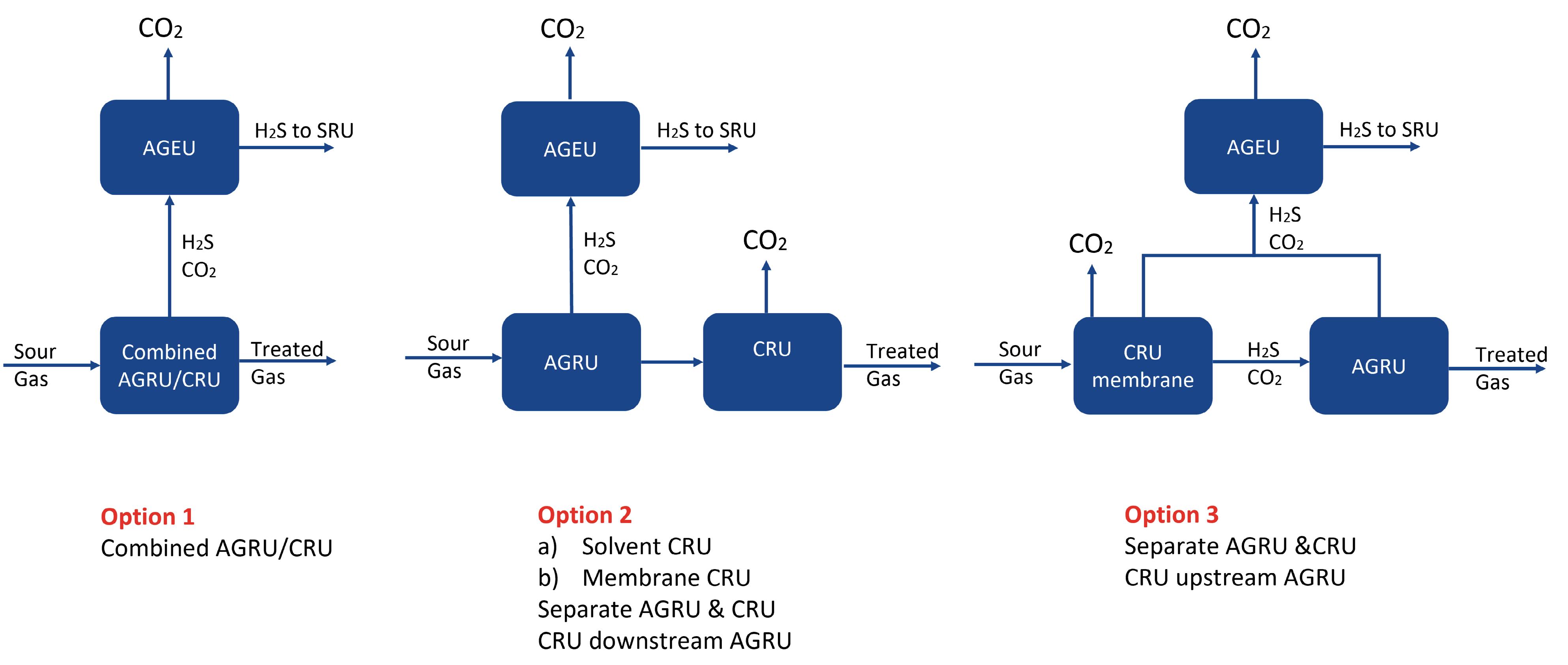
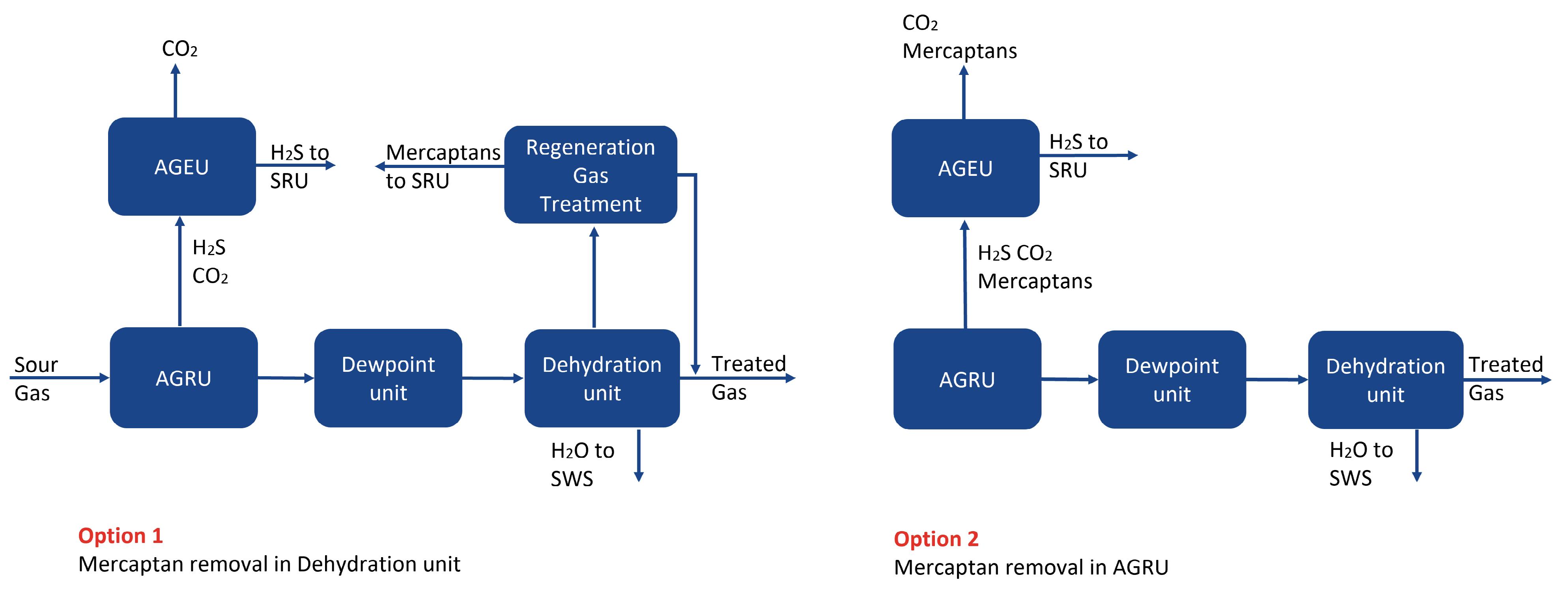
Figure 1. Location of the CO2 recovery unit (CRU).
Figure 2. Case 1: location for mercaptan removal.
Figure 3. Case 1: selection of an SRU. required to recover CO2 and concentrate the H2S in the feed to the SRU.
Option 2 considered a high-pressure AGRU with a selective solvent to preferentially remove H2S with either a high-pressure solvent based or a two-stage membrane CO2 recovery unit downstream. Although the AGRU solvent in this option had high H2S selectivity, the level of CO2 removed is higher than needed, and the acid gas stream still required an AGEU to concentrate the level of H2S in the feed to the SRU.
Option 3 has a two-stage membrane CO2 recovery unit upstream of a solvent-based AGRU. Whilst the size of the AGRU is reduced, this option required multiple AGEUs to concentrate the H2S and recover the CO2.
Option 1 with the combined AGRU/CRU was the recommended option for CO2 recovery because it has the smallest equipment count and layout, only one high-pressure absorber, and the lowest CAPEX and OPEX. The next step was to consider the location for mercaptan removal. Figure 2 shows the two options considered for mercaptan removal for Case 1. A molecular sieve unit is required downstream of the AGRU to remove water and heavy hydrocarbons in order to meet the required sales gas, water and hydrocarbon dewpoint specifications. The sour feed to the plant contains approximately 100 ppmv mercaptans, which need to be removed in order to meet the overall sulfur specification. Two options were considered for mercaptan removal. Option 1 is based on using a formulated chemical solvent in the AGRU and removing mercaptans in the molecular sieve unit. The molecular sieve regeneration gas contains heavy hydrocarbons, water and mercaptans. Water and heavier hydrocarbons are knocked out by cooling, but a physical solvent treatment unit is required in order to remove the mercaptans from the regeneration gas. Option 2 considers removing the mercaptans in the AGRU, using a hybrid solvent. The AGRU for Option 1 had a significantly lower solvent circulation rate, reboiler duty, and CAPEX and OPEX. There is uncertainty surrounding both the level and distribution of mercaptans in the sour feed to the plant. Option 1 is a more robust design, as the molecular sieve will be able to handle these variations. Option 1 with a chemical solvent and mercaptan removal in the molecular sieve unit was the selected option. The final step for Case 1 was to select the most suitable option for sulfur recovery. Option 1 with EUROCLAUS and

caustic scrubbing typically has fewer items of equipment and a lower CAPEX, but has higher chemical consumption and caustic waste. Although the removal efficiency is well above 99.9%, the recovery efficiency is only 99.3%, as the sulfur is not recovered to elemental sulfur, but removed from the gas stream, producing a liquid waste stream (see Figure 3).
Option 2, the formulated amine-based tail gas treatment unit (TGTU) option, can achieve over 99.9% sulfur recovery and more than 99.9% sulfur removal efficiency, as the sulfur removed from the gas streams is recovered as elemental sulfur.
For both options, due to the fact that the acid gas from the AGRU contains a low ratio of H2S/CO2, an AGEU is required to maximise the recovery of CO2 and to concentrate the H2S in the acid gas to the SRU to avoid co-firing. The recommended solvent was a sterically-hindered solvent as it had the lowest circulation rate, heating duty, CAPEX and OPEX. This same solvent can be used in the TGTU and therefore a common regeneration system can be used, reducing the number of items of equipment required, and therefore the CAPEX. Option 2, a two-stage SRU and TGTU with the same solvent as AGEU and common regeneration, was the recommended option.
The recommended options for Case 1 were: n Single AGRU using a chemical solvent to remove H2S and
CO2 from the sour gas. n AGEU using a sterically-hindered amine to recover CO2 in order to meet the required CO2 product specification, and concentrate the H2S in the acid gas to the SRU. n Molecular sieve selected for dehydration and heavy hydrocarbons and mercaptan removal. n Physical solvent treatment unit to remove mercaptans from the regeneration gas so that it can be routed to sales gas. n Two-stage SRU and TGTU – same solvent used in AGEU and TGTU, so a common solvent regeneration system can be used.
Case study 2
Table 3. Case 2 – acid gas components in feed
CO2
H2S 8 mol%
20 mol%
Mercaptans 200 ppmv
COS 100 ppmv
Table 4. Product specifications (Case 2)
Sales gas H2S < 15 ppmv; CO2 < 0.2 mol%; total sulfur < 60 ppmv; water < 0.1 ppmv
CO2 product stream CO2 > 96 mol%; HCS < 4%; H2S < 200 ppmv Sulfur product Minimum 99.9% recovery; SOX emissions < 550 mg/Nm3

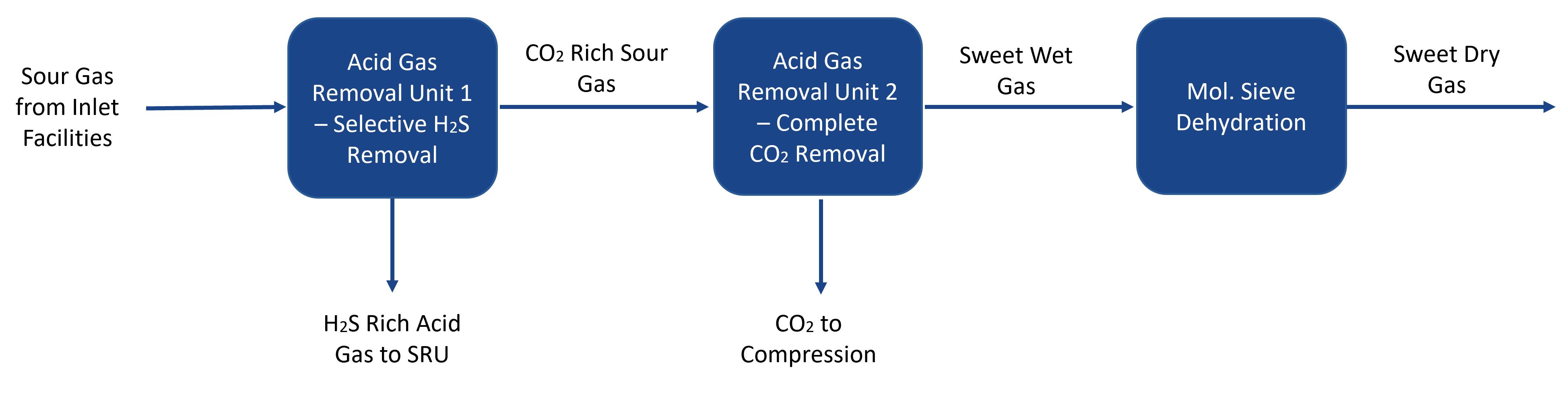
Figure 4. Case 2: locations of CO2 recovery.
Figure 5. Case 2: option 1, CO2 recovery. Table 3 shows the acid gas components present in the Case 2 feed stream, and Table 4 shows the required product and emission specifications. The Case 2 feed was 1000 million standard ft3/d at 35 bara and 25°C.
Similar to Case 1, the first step for Case 2 was to consider the location for CO2 recovery. For this case, three locations for carbon capture can be identified (see Figure 4).
Option 1 has two steps within the AGRU: first removing the H2S selectively, and then removing the CO2 (see Figure 5).
To achieve high selectivity at elevated pressure, the most selective amine available must be chosen, and the solvent circulation must be minimised. Additionally, to improve the selectivity, the solvent must be made as cold as possible, requiring extensive chilling. As a consequence of the minimised solvent circulation, the adsorption of mercaptans will be limited, thus passing them to the mole sieve unit. The mole sieve unit would then require a dedicated regeneration gas treater with a substantial additional equipment count.
After the H2S removal, the CO2 would still be very dilute in a large hydrocarbon gas flow, making this high-pressure absorber an expensive piece of equipment (high pressure, large diameter, stainless steel or clad). Since there were too many uncertainties (mainly on the selectivity of the H2S removal), and given that this option would require the CO2 absorption to be online all of the time to meet sales gas specification, this option was rejected. Option 2 considers CO2 recovery downstream of the TGTU when the TGTU solvent is hydrogenating/amine-based. If total acid gas removal is considered, the acid gas from the AGRU will contain between 60 – 70 mol% H2S. Considering the relatively large amount of acid components that need to be removed, solvent circulation is substantial. In this scenario it is best to use a hybrid solvent such that mercaptans are also adsorbed in the AGRU. For such concentrations, acid gas
enrichment is typically not required, and the acid gas can be routed directly to the thermal stage of an SRU. The SRU can be air blown, but this will result in a substantial dilution of the CO2 by the nitrogen from air, making it difficult to absorb the CO2 downstream of the TGT absorber. Alternatively, the SRU can be fired with pure oxygen, resulting in a TGT off-gas stream that contains more than 70% CO2. This will substantially reduce the cost of the SRU/TGTU, as the equipment can be made much smaller, but comes at the cost of making pure oxygen, which requires an air separation unit. In this scenario, CO2 can be removed either with conventional amine-based technology, or with a cryogenic system. After the CO2 is removed, the remaining gas is nearly pure hydrogen which, with some additional cleaning steps, can be recovered as a valuable byproduct.
Another option is to recover the CO2 downstream of the thermal oxidiser. To do this, the gas from the thermal oxidiser has to be cooled and quenched to 55°C (typically). Since traces of sulfur trioxide (SO3) can be present, the gas is very corrosive, and a quench venturi/caustic scrubber needs to be applied. Depending on the SRU technology used (e.g. EUROCLAUS or SUPERCLAUS), the SO2 content in the flue gas can be several hundreds of ppmv. This SO2 has to be removed before the gas can enter the CO2 absorber by adding caustic to the quenching liquid. Otherwise, the SO2 will end up in the CO2 product and the CO2 specification cannot be met. This quench system is considered to be very expensive, but in combination with EUROCLAUS/SUPERCLAUS it more or less balances out with Option 2. However, considering the amount of sulfur produced and hence the amount of SO2 that needs to be scrubbed, the cost and effort for continuously handling caustic becomes prohibitive. For these reasons, this option is not further considered for this case.
The recommended options for Case 2 were: n AGRU using a hybrid solvent such that not only H2S and
CO2 are removed, but also the bulk of the mercaptans. With this solution, the mercaptans from the mole sieve enter the
SRU in a gradual flow, and large peaks are avoided. n A mole sieve unit is considered for both dehydration and deep mercaptans removal. The regeneration gas from the mole sieves is compressed and recycled to the front end of the main absorber. n The SRU/TGTU will be operated with pure oxygen, such that the TGTU off gas contains only water, CO2 and hydrogen, with traces of CO and carbonyl sulfide (COS), all within the required CO2 gas specification. The hydrogen can be recovered as a high-value product. If the hydrogen is not recovered, it can be burned in the thermal oxidiser, which reduces fuel gas requirement.
Conclusion
The two examples of gas field developments show the importance of understanding that the optimum design is dependent on feed and product specifications. As no feed is the same, no design should be the same. It is important to consider the implications of the selected design of one unit on all of the other units. It is also important to consider the impacts of changing compositions, rates and conditions throughout the lifetime of the plant to ensure future-proof, successful plant operations.