CLEAN PROCESS


We understand how you need to reduce complexities at your plant.
+ CLEAR
strengthen your plant’s safety, productivity and availability with innovations and resources.
you want to learn more?
helps you to improve your processes:
of safety instruments that
regulations
PROGRESS You
Do
www.endress.com/oil-gas Endress+Hauser
• With the largest portfolio
comply with international
• With applied technologies and people who have extensive industry application know-how • With access to accurate and traceable information

December 2022 8 HYDROCARBON ENGINEERING
Stefan Chapman and Miro Cavkov, Euro Petroleum Consultants (EPC), detail the role of downstream operations in promoting sustainability within the energy sector.
As the pace of climate-neutrality accelerates, the role that the downstream oil and gas industry plays in ensuring these goals are met efficiently and affordably is advancing. All regions are looking for energy security alongside the delivery of a successful energy transition, all the while coping with rising costs. Living in an uncertain world, the energy sector is now faced with the complex pressures of balancing security and growth with decarbonisation. In this ever-changing environment, the downstream industry is also evolving, with boundaries between upstream, midstream, downstream and power becoming blurred. Whether it is reduce, recycle or remove, success will be defined by clear, significant and concrete targets.
Historically, the downstream oil and gas sector has always been considered a sustainability driver in terms of being an energy security supplier and a major provider of petroleum derivatives and products. Today, refining technologies have enabled producers to operate assets efficiently and reliably, where each drop of crude oil and each group of molecules is managed, almost eliminating lower-value products. The result is visible, and modern life simply would not be what it is today without the support of the downstream oil and gas industry. The majority of transportation – whether personal, commercial, by land, sea, air or rail – relies on liquid or gaseous fuels, produced by the downstream sector. This is also the case for petrochemical products, which facilitate our daily lives and touch every industry: health, communications, construction, etc.
Demand drives the market, and susequently production. Technology innovations from the last few decades have provided endless possibilities, most of which were unimaginable just a century ago. However, fossil fuels are not renewable and at some point crude output will begin to decrease. Predictions clearly show this trend – even if it will take some time. So, in truth, the current energy transition agenda is not just a technology issue, but

December 2022 9 HYDROCARBON ENGINEERING
rather a global sustainability plan, whereby achieving climate goals (on time) will be crucial for future generations, and will need to be balanced with the increasing global energy demand.
Downstream assets: an essential part of the solution
The question is: how can today’s refineries play an integral role in reaching climate goals? Downstream producers have been proactive in looking at ways to reduce their environmental footprint, whilst being key energy providers and remaining competitive in difficult conditions. Each asset or complex should be treated individually – there is no ‘silver bullet’ solution that is applicable to every facility. The first step for all major refiners and petrochemical and chemical companies is to improve present operations by increasing energy efficiency and reliability, and reducing current emission levels from existing facilities. Reaching these ‘low hanging fruit’ is a priority.
Other routes are being evaluated, such as further refining and petrochemical integration opportunities, and diversification by way of co-processing with bio-feedstocks, and the implementation of plastic recycling technologies. In reality, the world is still heavily reliant on mid-distillates and diesel, even in a declining market, and this has to be balanced
with climate regulations that are being introduced, where Scope 1, 2 & 3 emissions will be part of the benchmark for success.
In order to remain competitive and meet changing demands, operators must adapt their existing assets in a sustainable way, requiring extra production and technology flexibility. As an example of this, the most used liquid fuels worldwide are gasoline, diesel, jet and marine fuel, and these can now be produced from sustainable feedstock – either 100% sustainable, or as a blend with conventional feedstocks.
Currently, there is general interest in hydrotreated vegetable oil (HVO) and bioethanol, since these fuels (or components) can be designed in such a way that they can be a drop-in solution, meaning that internal combustion engine (ICE) powered vehicles will not require any interventions in order to run on these sustainable and blended fuels.
There is clear evolution in the field, with the elimination of issues from first-generation biofuels. Newer generations have great cold filter plugging point (CFPP) standard properties, which have unlocked a major new opportunity: sustainable aviation fuel (SAF). Sustainable fuel technologies are available, scaled up, and will be ready to meet future demand. In terms of implementing these new technologies, the question that operators face is whether it is better for them to be the front runners or the fastest followers. Each company needs to weigh up the pros and cons of this.
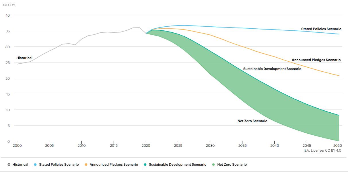
Figure 1. CO2 emissions in the IEA’s World Energy Outlook 2021 scenarios: 2000 – 2050.
Producers are having to balance securing their business and remaining competitive whilst looking to reshape the downstream industry into a lower-carbon model – and this is no easy task. An added difficulty is that even in a disrupted oil market, renewable feedstocks and fuels remain less cost competitive when compared to their fossil counterparts. In this case, businesses and society have to understand that the sustainable and renewable future we are aiming for will have different dynamics and different variables, compared to the traditional forms of energy.
Hydrogen: the designated game changer
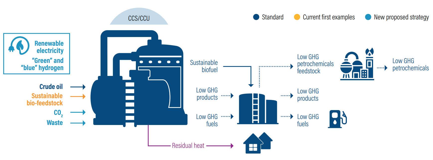
Figure 2. Concawe’s conceptual low-carbon refinery, feedstock and products in 2050.
Hydrogen, especially green, has been touted as the ‘Holy Grail’ of the sustainability journey – a major decarbonisation medium and possibly the ultimate solution. This can be seen in many high-level industry
December 2022 HYDROCARBON ENGINEERING 10


... your reliable partner for rotating equipment SBW Group Seven Decades of Progress Head Office & Manufacturing: Shenyang, China www.sbw-turbo.com qiming.chen@sbw-turbo.com (Europe & Middle East) Abu Dhabi, UAE tony.parish@sbw-turbo.com (Europe & Middle East) London, UK anding.xiang@sbw-turbo.com (USA & Americas) Charlotte (NC), USA For more information, visit our website www.sbw-turbo.com, scan QR for our brochure, or contact: In 1960, SBW manufactured their first own-design centrifugal compressor in the original Shenyang factory (background image). New milestones regularly followed, across key process sectors . . . 1979 – Olefin plant compressors (115 000 tpy) 1982 – Ammonia/urea plant (520 000 tpy) 1989 – Hydrocracker compressor (800 000 tpy) 2003 – Axial/centrifugal ASU compressor (40 000 nm3/hr oxygen) 2010 – First PTA plant compressor (600 000 tpy) 2011 – High-thrust reciprocating compressor (125 t thrust) 2017 – Air separation for 100 000 nm3/hr oxygen 2021 – PDH plant, 900 000 tpy (world’s largest using Lummus-process) DMCL1706+2MCL1707 2021 – first 1.4 million tpy Olefin plant (74 MW cracked gas; 39 MW propylene; 24 MW ethylene) CNPC Guangdong
discussions, current investments, and potential projects. However, as aforementioned, a successful future energy mix will be a combination of several alternative energy solutions.
In the case of hydrogen, there remain a number of hurdles to overcome. These include the scalability of green hydrogen production, existing and future infrastructure, market demand, consumer willingness, and the ability to cope with the energy transition. Scaling up of electrolysers is already underway, confirmed by Norway’s HydrogenPro project – the largest industrial electrolyser built so far, with a diameter of 2 m. Additionally, there is Germany’s 24 MW installation in the Leuna facility, and the 8.75 MW PEM electrolyser in Wunsiedel.
Western Europe is very much at the forefront in terms of green hydrogen production. Many countries are investing and developing infrastructure to allow for further implementation. Building sustainable infrastructure is critical, and reliable government and EU regulations are required for its successful implementation.
Europe already has a strong gas transmission network, which could potentially be used in certain circumstances. However, these existing pipeline networks have been designed to transport natural gas, and so simply switching to 100% pure hydrogen is not possible, as hydrogen can easily diffuse through metal surfaces. Additionally, hydrogen is a much smaller molecule than methane in natural gas, which means that leakage rates though pipeline walls and joints may be greater, resulting in increased safety concerns and economical issues. Certain metal pipes used for transporting natural gas may also degrade over time when exposed to hydrogen, especially in the presence of high temperatures and pressures.
However, if blending of hydrogen and natural gas is considered then these networks could potentially become an option. Of course, complex engineering challenges remain in the repurposing of existing networks, in order to safely transport natural gas blended with hydrogen through more than 200 000 km of transmission pipelines across 2 million km of distribution network that has over 20 000 compressor and pressure reduction stations in Europe.

Unfortunately, there is no quick method to investigate whether a pipe might become compromised due to hydrogen exposure, as this damage takes time to manifest. As such, precise studies and empirical tests are currently being performed. In-depth knowledge of pipeline systems, as well as the implementation of accurate risk assessment and gap analysis, will enable network owners and operators to determine the safe proportions of natural gas to hydrogen when blending. This solution could result in the supply of lower-carbon-intensity energy to end users.
The green hydrogen solution has merit. Once the engineering challenges are overcome, and the technology, infrastructure and consumer behaviour is in place, hydrogen will deliver significant environmental benefits. Notably, green hydrogen can leverage periods of low sunlight and wind, and can also act as a battery. It is an energy carrier that can ensure energy supply in times where renewable sources are not in their highs. As an energy carrier, it can be stored in a liquid organic form as ammonia (NH3), which requires 125 psi (862 kPa) of constant pressure and temperatures of below -33.6 °C, while pure hydrogen requires temperatures of as low as -252.87°C and a pressure of 14.7 psi (10.3 kPa) to transform into liquid form.
From this simple comparison it is clear that the storage and transportation options for liquid organic hydrogen carriers (LOHCs) suggest that this is a more promising solution. One thing is for certain: hydrogen will be a substantial part of our future, but it will not be the only sustainable solution.
Conclusion
The downstream industry has a role to play in securing a sustainable future, and should be seen as part of the solution. At the last COP26 conference, the lack of downstream sector representatives elevated concerns that governments intend to solve the energy issue without the expertise and experience of the sector, and in the case of carbon, the complexity of the problem is not being fully recognised.
There is a distinct mismatch between the want to have zero emissions, and the transition that must happen in order to realise it, as well as a lack of dialogue between those making policies and those required to deliver it. Without the input of the industry, poor decisions are likely to be made, with sub-optimal outcomes. A recent example of this is the ban of plastic straws, which had no material impact on consumer polymer use. Rather, the replacement material created more carbon emissions.
An open dialogue is needed in order to deliver a more logical and efficient energy transition that will result in lower emissions. By keeping some of the cleaner fossil fuels active, the most carbon-intensive fuels would be displaced. There is a lot that can be achieved at present that may not result in neutrality, but would escalate progress. Ours is a transition that demands acceptance that it will not gain overnight; it will instead require a number of steps in order to land upon sustainable solutions that will solve our sustainability challenge.
December 2022 HYDROCARBON ENGINEERING 12
Figure 3. Europe’s existing gas transmission network.
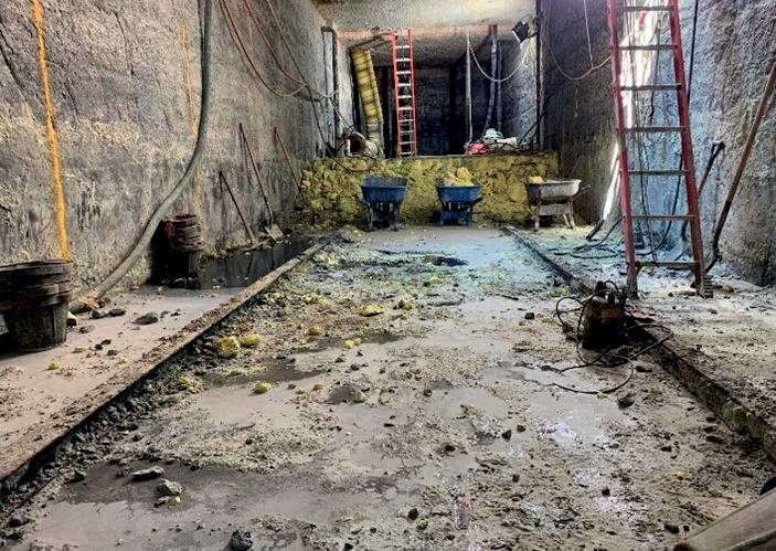
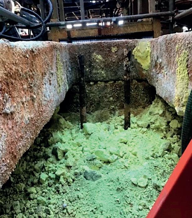
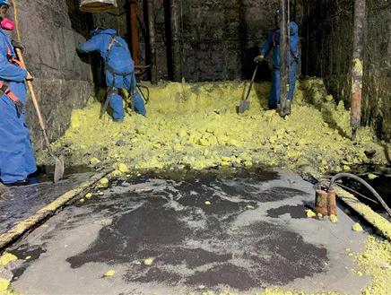
Managing all the processes in a sulfur recovery unit (SRU) is arduous work—demanding skill, concentration, and dedication through every shift. Fortunately, the reliability, accuracy, robust design, and operating ease of AMETEK analyzers can make that tough work a little easier. AMETEK engineers have been designing industry-standard SRU analyzers for decades, and that shows in the products’ accuracy, reliability, and longevity.
Because we make analyzers for every part of the process—from acid-feed gas to tail gas to emissions, including the gas treating unit, sulfur storage (pit) gas, and hot/wet stack gas you get the convenience of one source for unparalleled engineering and support for all your analyzers, while your operators benefit from consistent interfaces and operating procedures. For decades, we’ve been dedicated to making your SRU operation the most efficient it can be for the long term. Learn more at www.ametekpi.com/SRU.

© 2021 by AMETEK Inc. All rights reserved.
Sulfur recovery unit workers have a lot to worry about. Analyzers shouldn’t be one of them.
Daisy Chen, Amazon Web Services (AWS), USA, discusses how cloud-enabled equipment health and maintenance (EHM) is improving the reliability, performance, cost control and safety of downstream companies.


equipment health and maintenance (EHM) solutions that help improve critical equipment reliability and performance through real-time visibility to equipment performance and early indications of equipment failure.
ENGINEERING
14 December 2022 HYDROCARBON

December 2022 15 HYDROCARBON ENGINEERING
EHM is playing a key role in the implementation of predictive maintenance. The US Department of Energy (DOE) has stated that predictive maintenance saves 8 – 12%
over preventative maintenance costs, and upwards of 40% over reactive maintenance costs.
EHM utilises advanced machine learning (ML), analytical applications, visualisation, and alerting capabilities for critical equipment monitoring and proactive anomaly detection in order to enable effective maintenance scheduling. By overlaying operational insights provided by EHM with equipment maintenance history records, companies have lead-time to take field action such as equipment optimisation and proactive maintenance planning. EHM gives downstream companies the ability to reduce unplanned downtimes and optimise equipment life cycles which, in turn, help them to optimise maintenance planning and the associated costs.
Figure 1.
occur.
Figure 2. The EHM solution from AWS is a cloud-based offering that provides predictive equipment analytics to monitor equipment health and performance and boost preventative maintenance strategies, which helps reduce equipment downtime and optimise performance.
EHM solutions help downstream companies maximise value from existing equipment infrastructure. EHM aggregates operational data from data historians or equipment sensors, equipment records, and maintenance work histories, to provide contextualised insights that support predictive maintenance efforts. With the ability to model and view field equipment performance, companies can increase equipment utilisation, prioritise maintenance efforts, optimise maintenance costs, and reduce operational risks.
The EHM solution from Amazon Web Services (AWS) utilises a variety of services to drive its cloud-based applications. These include AWS IoT Core, AWS Database Migration Service, Amazon Aurora, Amazon Simple Storage Service (Amazon S3), AWS Lambda, Amazon Lookout for Equipment, and Amazon SageMaker, all of which provide performance monitoring and enable predictive maintenance at scale, which is critical for downstream companies seeking to leverage digital transformation to improve equipment reliability and overall performance.
Case study: predictive maintenance at an Australian natural gas facility


When a leading Australian natural gas producer announced an ambitious goal to increase operational efficiencies by 30% over three years through technology innovation and analytics, it faced the following common technology challenges:
n Different teams were using several manual processes across different systems, and they needed a workflow that could run across the top, integrating all of these manual steps into an automated process.
n Data needed to flow continuously from onsite equipment to analytics systems, but much of its infrastructure was old and was not designed to support real-time data capture, transfer and access.
n Data was stranded in disparate siloes, and a multi-layered solution was required to bring data to a central location quickly and securely, and make it accessible to analytics teams and decision makers across various systems, such as maintenance and permit.
Figure 3. Leveraging AWS for a customised, condition-based maintenance project, a leading Australian natural gas producer reduced the cost of routine inspection and service by 80%.
To address these challenges, the company developed a cloud-based condition-based maintenance (CBM) system to improve equipment visibility for analysis, troubleshooting and maintenance for 1500 cooling fans in its LNG
December 2022 HYDROCARBON ENGINEERING 16
Predictive maintenance applications for downstream oil and gas operations can help operators reduce costs and downtime by identifying equipment failures before they
processing facility. The CBM project goals included detecting equipment failures before they occur, reducing time from detection to repair, automating mundane processes, and minimising the number of hours to which staff in the field are exposed.
Leveraging cloud-based IoT infrastructure and services, the company developed and implemented wireless IoT vibration sensors to understand the condition of the fans. The sensors transmitted data back to a centralised cloud-based data lake across a wireless LoRaWAN network and managed cloud-based IoT data services to handle edge applications, device data routing, and storage.
The company used a managed ML development service to build customised ML models to perform continuous analysis on data in production in order to determine equipment condition, detect defects, and assign a health score to every machine every three hours. This enabled the company to automate responses so that detected defects could be entered into the CBM app to generate a fully-resourced work order with a permit and isolation certificate. ML models were also developed to automate the company’s work planning process, and enabled templated, automated steps and responses, eliminating the need to build artefacts and work orders from scratch.

Collecting and analysing cooling fan data was performed manually every three months. The company was able to increase the interval of cooling fan field data capture to every 15 minutes to provide near real-time monitoring. ML-driven workflow automation reduced the average work planning process from 80 days to one day. The cost of routine inspection and service was reduced by 80%, and the company expects to reduce that to 90% as it continues to train the CBM algorithms. The company is also able to utilise staff for more productive activities, with capacity for further innovation – including beginning similar CBM work on its pumps, valves and turbomachinery.
Service for peace of mind
We have checked the operation behaviour, scheduled maintenance and installed updates. As your service partners, we keep your business running smoothly, securing availability and efficiency 24/7, around the world, on-site and digital. We’re there – so you can be away from time to time.

Get support at www.man-es.com/primeserv

Our service supports you
easily possible at lower costs than before. Their capabilities now extend to on-premises and the edge, which increases the possibility of transitioning critical business services to the cloud while ensuring the least disruption.
Software product categories are converging, which is simplifying cloud migration
Fewer separate point solutions are required as major product categories have started to become increasingly integrated and are available as a seamless capability on the cloud and often as SaaS. For example, Asset Performance Management is becoming more integrated with products that integrate asset registers, strategy libraries, real-time performance monitors, integrity risk tools, as well as predictive maintenance. Similarly, Manufacturing Execution Systems are becoming far more integrated with the ability to plan, schedule, manage production operations, and extend into dispatch and supply chains from within a single product. These trends make it easier for industries to adopt purpose-built cloud technologies.
Embedding AI/ML capabilities across software applications is easier
As analytics becomes mainstream in industries, it is increasingly being embedded within major software products in the market. The cloud allows for building and scaling industry-specific analytics capabilities. This reduces barriers of availability of skills and the need to create artificial intelligence (AI)/machine learning (ML) use cases that are specific for each site and manage disparate sets of data.
Cybersecurity capabilities on the cloud have significantly improved
Cybersecurity compliance is becoming more streamlined with increased adoption of standards such as IEC 62443 for industrial automation and control system cybersecurity, ISO-27001/270002 for information security management, ISO-27017 for information security controls for cloud services, and ISO-27018 for the protection of personally-identifiable information in public clouds. Availability of AICPA SOC 2 audit reports also helps when companies consider SaaS or other cloud vendors in their journey to adopt cloud technologies.
Availability of industrial SaaS applications
Industrial companies are often perceived as late adopters of digital technology. Most industries have preferred to stick with on-premises software solutions, largely due to the lack of suitable SaaS options at a cost that is viable to many of them. This is rapidly changing with several industrial software capabilities delivered as a service. These capabilities include foundational infrastructure such as data, analytics and production insights, in addition to major software applications such as manufacturing execution systems, asset performance management, and remote operator training.
Five capabilities for the industrial cloud
Strategically thinking about the role of the cloud for industries requires more than a consideration of technology. Most industries have already initiated some form of digitally-enabled business transformation programmes. An incremental and agile approach to cloud transformation reduces risk and avoids business disruption when compared with large and expensive rip and replacement of existing systems.
Making cloud for industries easy to adopt across the organisation requires tailoring capabilities that address long-term needs for the industry. These clouds must bring together common industrial data models, industry-specific standards, business workflows, application programming interfaces, and interoperability with multiple clouds. There are five capabilities that industrial organisations adopting the cloud must create:
Industry-specific building blocks
Each organisation must develop common capabilities that scale across the boundaries of its enterprise to address industry needs. These are modular building blocks that speed up the development of industry-specific digital solutions. Examples of these are shared building blocks such as asset models, process models, simulation engines, and/or planning and scheduling models, which allow applications to consume as a common resource on the cloud.
Cross-application architecture blueprint
An industry-specific architecture that covers all aspects beginning with data, network, computing infrastructure, and the range of applications will serve as a blueprint for enabling industrial cloud transformations. Industry clouds require an industry-specific blueprint, against which organisations can modernise and innovate capabilities that are most relevant for their business.
Openness and interoperability
Cloud applications for the industry must be thought of as a highly-interoperable ecosystem of applications that must be capable of maximising existing software investments such as their current on-premises environment. A successful industrial cloud will drive an increased level of openness and interoperability, while promoting a common view across the enterprise.
Cybersecure foundation for connectivity, data and access
Building an enterprise-wide data, analytics and connectivity model is critical in order to function in the new world of cloud. Cybersecurity threats are risks that must be managed for both information and operational technology applications. These threats are ever-changing. In order to fully exploit the benefits of the cloud, a foundation to manage cybersecurity must be built, starting with connectivity and then extending to data and access.
December 2022 HYDROCARBON ENGINEERING 22
Secure integration for partners
There are currently multiple cloud environments from different providers. The landscape is even more complex if we consider the overlap between many SaaS and Infrastructure-as-a-Service (IaaS) providers. Most companies who started their cloud journey seem to have focused on proving their success with a single cloud provider. Over time, the ability to integrate and operate across multiple cloud ecosystems is an important building block in order to fully exploit an open ecosystem with partners.
Where to start?
One of the most important questions that industries try to answer is where to start. Generally, business leaders either expand their cloud transformation efforts to cover operational technology and industrial applications or start with a new industrial cloud journey. In order to develop a phased roadmap with the right governance, there are five principles to follow:
Start with a business context and a problem to solve Cloud transformation journeys must be aligned with business objectives and have a shared context with the overall strategy for the organisation. As a first step, picking a problem to solve with a cloud-enabled business value will help set the stage for future transformation. For example, enterprise-level production insights to improve economic planning across multiple production sites will provide a basis for additional capabilities.
Build the data foundation and establish interoperability
Operational technology and industrial software applications are largely built on-premises where they have been used for several years. Expanding their availability using the cloud requires breaking down siloes and creating broad availability of industrial data for consumption by new software applications and users.
A clear strategy for how to connect to different equipment and applications to collect, contextualise, store and scale data must be established. Wherever possible, common master data must be used between applications, with shared assets and process models utilised through extensible application interfaces. This will enable increased levels of interoperability.
Select new capabilities to build on the cloud
Add new technology capabilities to the cloud that can be shared across the entire organisation. These are capabilities such as data science tools, common enterprise applications, data visualisation templates, and ML models. This helps future-proof investments by adopting new capabilities that can be exploited using the cloud at a scale that was not possible before.
Shift workloads with a roadmap, and plan for a transition period
Moving to the cloud does not have to be wholesale. While workloads are moved between on-premises and the cloud, industries should plan for a hybrid period where an overlap will exist between the current infrastructure and the new cloud infrastructure. The goal of a successful transition includes setting up new infrastructure and software management processes to minimise disruption such as high availability, disaster recovery, and testing on the cloud.
Capabilities to have on the cloud must be determined in order to build a migration roadmap. Industries that adopt software must shift from a focus on software applications to a focus on outcomes. With a focus on outcomes, industries must choose which applications to transform in the cloud, which to simply migrate, and which to keep as-is. Certain legacy systems may never be migrated to the cloud for technology, commercial, or regulatory reasons. Regional differences for data sovereignty or regulatory requirements must be assessed for each industry and the products that are produced. A roadmap must be built which defines how to sequence these capabilities and regions. During the transition period, deployments to existing data centres must be by exception, and all new investments must be cloud-first or cloud-ready.
Build the organisation around these new capabilities
New capabilities built on the cloud will require changes to the current organisation to enable adoption and realise value. For example, adoption of an open and interoperable ecosystem across multiple industry stakeholders will require setting up business processes that facilitate collaboration with customers and partner organisations. This will also require governance around aspects such as cybersecurity through intrusion prevention, and detection and response. The organisation structure must be built with the right incentives to ensure that new opportunities presented by the cloud are utilised.
Why the time is now?
We are now in a phase of mainstream adoption of the cloud within industries. The increased maturity of industrial cloud technologies makes adoption easier and provides faster time to value. Preparing for volatility and uncertainty in the world also requires industries to adopt new cloud-enabled capabilities such as remote operations and production insights while increasing the digital inclusion of people.
All of these factors make now a suitable time to adopt cloud transformations. These allow industries to achieve operational excellence, improved sustainability, end-to-end process optimisation, increased reliability, and better workforce productivity. In utilising the cloud, industries can embrace bold strategies which create a future that is more efficient, safer, and sustainable, and is also inclusive of all people in the workforce and society.
December 2022 HYDROCARBON ENGINEERING 23

December 2022 24 HYDROCARBON ENGINEERING
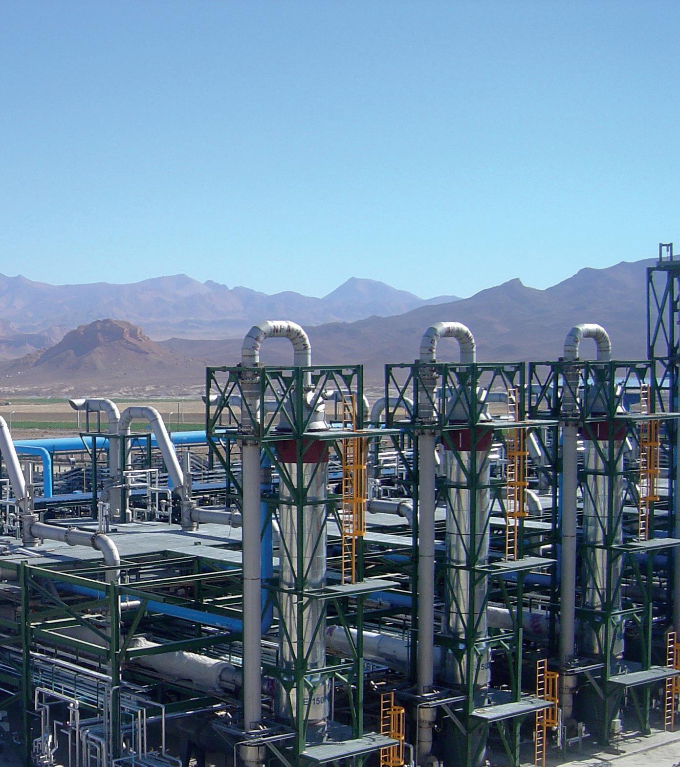
There is no doubt that the most important development in carbon black production has been the introduction of furnace blacks. Today, the furnace black process accounts for more than 95% of carbon black production worldwide, this process being the most modern way of manufacturing this important building block.

Eurotecnica’s proprietary ET BlackTM Carbon Process is a high-yield furnace black process. It combines a high degree of economy of scale with the flexibility of producing a wide spectrum of carbon black grades with a single reactor.
The production of carbon black in the ET Black process is accomplished by the partial combustion and thermal decomposition of highly-aromatic residual oils at high temperatures, in horizontal closed reactors. Temperatures range from 1400°C to 2000°C, depending on the type of carbon black produced, whether it is a soft black or hard black grade, and the specific reaction times for each grade.
In the downstream part of the reactor, at selected intervals, water is injected to perform quenching of the carbon black laden gases. The sequence, intensity and duration of quenching confers the carbon black product-specific characteristics that differ from grade to grade. Several specifically-designed heat exchangers allow for the efficient recovery of the massive amount of heat that is generated in the reaction.
A carbon black plant designed and implemented for ADNOC’s refinery in the UAE has proven the level of performance that is achievable by the ET Black process, and its ability to produce high-end grades (N115, N220) out of relatively poor, low Bureau of Mines Correlation Index (BMCI) feedstock.
This experience has demonstrated the benefits that a refinery can experience by taking advantage of the so-called ‘bottom of the barrel’ as feedstock to produce carbon black – a valuable group of commodities applied in several industrial sectors.
There are many advantages to investing in a carbon black plant – for the refinery itself, for the local community and, broadly, for the global environment. For instance, low-value residuals, such as FCC decant oil, are difficult streams to use in a refinery for anything other than burning it completely, generating large amounts of greenhouse gases. As this type of feedstock has certain characteristics of high aromaticity, it is perfect as carbon black feedstock. The advantages for those refineries considering setting up an ET Black carbon black plant are numerous:
n The production of a valuable commodity that is priced at US$2000/t on average, which is generally in high demand.
n The refinery is enriched with top technology and several highly-qualified jobs that it generates.
n Entry into a growing market.
n The production of carbon dioxide (CO2) is halved; roughly half the feedstock becomes carbon black instead of simply being burned.
December 2022 25 HYDROCARBON ENGINEERING
Stefano Sassi, Eurotecnica, Italy, explores the environmental benefits of carbon black production within a refinery.
n Around half the sulfur contained in the feedstock is captured.
n The residual emissions are virtually zero.
While the first advantages are rather obvious, the latter demand further detail.
Emissions to air: halve the production of CO2
When a refinery cannot sell oil residues to the market, there are no alternatives to burning it, resulting in the 100% transformation of the carbon into CO2. However, adopting a carbon black plant is a way to use such streams and turn them into a valuable product. Since the yield is around 50% –depending on the grades produced – only the balance
becomes CO2, allowing for a significant reduction of that greenhouse gas (GHG). Other types of emissions from a carbon black plant are produced in very low quantities, if not traces. Table 1 lists these.
Tail gas venting
An important potential source of emission to the air is the ‘tail gas’. Tail gas comes from the reactor following product separation, and is a low calorific gas with a high moisture content due to the quench water vapour. It contains hydrogen (H2), carbon oxides (CO and CO2), reduced sulfur compounds (H2S, CS2 and COS), sulfur dioxide (SO2), nitrogen compounds (N2, NOX, HCN and NH3) and volatile organic compounds, such as ethane and acetylene.
The tail gas composition can vary considerably according to the grade of carbon black produced, and the feedstock used. Carbon black yields can be up to 65%, depending on the grade produced and the raw materials used. The presence of sulfur compounds in the tail gas (sulfur oxides, H2S and volatile organic sulfur compounds) depends on the feedstock sulfur content.
As a rule of thumb, only half of the sulfur contained in the feedstock does turn into sulfur oxides (SOX), as the balance stays in the final carbon black product. Around 2.5% sulfur content in the feedstock is still acceptable, because for several grades of carbon black – those applied in the rubber applications – the sulfur takes part in the downstream process of vulcanisation.
Figure 1. An operator at an ET Black carbon black plant.
Table 1. Emissions produced by a carbon black plant
In many standalone plants, the standard requirement for tail gas treatment is flaring. However, methods for recovering the energy content of the tail gases are more frequently employed than in the past. For instance, tail gas combustion is becoming common practice. The combustion of tail gas generates flue gas with different environmental characteristics.
Venting of non-combusted tail gas may be allowed during emergencies, start-up and shutdown periods, and during periods of grade change. Typical ranges of carbon black tail gas composition are provided in Table 2. However, these values do not reflect the full range of tail gas compositions encountered in all the carbon black facilities. Significant variations occur due to the different feedstocks used and carbon black grades produced.
Emissions from dedicated tail gas combustion devices
Gaseous toxic and odorous
from the tail gas, such as H2S, volatile organic sulfur compounds (CS2, COS), and CO are controlled with thermal combustion such as flares, boilers or incinerators. Thermal combustors can achieve complete oxidation of organic compounds, and can oxidise sulfur compounds in the flue gas process.
December 2022 HYDROCARBON ENGINEERING 26
emissions
CO n Product of incomplete combustion in the
n Product of
SOX n Oxidation of feedstock sulfur compounds in the reactor n Oxidation of sulfur
Reduced
compounds
n Decomposition and partial oxidation of feedstock
compounds in the reactor NOX n Oxidation of feedstock nitrogen compounds in the reactor n Thermal NOX from the reactor n Fuel NOX from dryers,
n Thermal NOX from dryers,
n Oxidative post-treatment of
n Incomplete decomposition of feedstock
the
n Incomplete decomposition
n Slip through
n Slip through
n Slip through
n Fugitive
n Present
Emission Origin
reactor
incomplete combustion in dryers, boilers, flares, etc.
compounds present in the tail gas
sulfur
(H2S, CS2, COS)
sulfur
boilers, flares, etc.
boilers, flares, etc.
carbon black with NO2 or HNO3 Volatile organic compounds (VOCs, e.g. methane, acetylene, ethylene
in
reactor Polycyclic aromatic hydrocarbons (PAH)
of feedstock Particulate matter (e.g., carbon black dust)
filter system behind reactor
dedusting filter systems, e.g., behind dryer
thermal combustor (e.g., boiler, flare)
emissions due to storage, transportation and packaging Heavy metals
as trace impurities in some feedstock
Combustion efficiencies of 99.6% for H2S and 99.8% for CO have been measured for a flare of carbon black. Particulate emissions may also be reduced by the combustion of some of the carbon black particles. However, SO2 emissions are increased due to the oxidation of H2S and volatile organic sulfur compounds. Additionally, it is important to realise that the combustion will also increase the emissions of nitrogen oxides. In Europe, the recovery of energy from the tail gas in the form of heat, steam and/or electricity is common, and the same applies to the ET Black plant at ADNOC facilities. The combustors usually treat some 70% of the generated tail gas; the remaining 30% is normally used as fuel in the dryers of the wet pelletising unit.
Emissions from the dryers of the wet pelletising unit
The wet pelletised carbon black is transported to a rotary drum dryer, where the wet pellets are dried. Tail gas is generally used as a heat source, as it aids the reduction of fossil fuel consumption. The flue gases’ heated dryer can be combined into one common stack with the evaporated water from inside the dryer.
Filter system vents

Carbon black is separated from the tail gas in the main bag filter, consisting of a special type of bag filter. Carbon black that is not captured in this filter is entrained in the tail gas. Normally, levels of carbon black in the tail gas after the filter are < 100 mg/m3. As the slip of carbon black in this filter represents a loss of product, there is a drive for the operator to keep the level as low as
possible. The collected (fluffy) carbon black is pneumatically-transported by air to another bag filter system, where the carbon black is separated from the transport air and subsequently fed to the pelletiser. The emissions from this filter are released into the atmosphere. Emission levels from this filter are generally < 50 mg/Nm3

Fugitive emissions
Fugitive emissions of carbon black (particulate matter) originate from cleaning, spills, and leaks in handling, packaging, storage and transportation. Fugitive emissions can be insignificant when the operator adheres to ET Black guidelines.

Get the latest launch news: servomex.com/signup THE NEW SERVOTOUGH SpectraExact 2500 The new SERVOTOUGH SpectraExact 2500 upgrades the photometric gas analysis of its trusted predecessor, delivering an advanced solution to your process, in an easier-to-use package, leading the way for application solutions in a range of industries. • Ethylene production • Carbon capture and storage • Ethylene dichloride • Direct reduction iron production MEET THE NEW BOSS RUGGED RELIABLE READY
Tyres are by far the
Figure 2.
largest single market for carbon black.
Emissions to air
Due to the large variety of plant configurations, feedstock compositions and product types, it is difficult to present an overview of emissions from carbon black plants that fits all plants. Some plants operate with separate stacks for the tail gas combustion units and for the product dryers, whereas others combine the flue gases from these sources.
Emissions to water
Water is used in relation to the production process or used for non-process-related utilities. The following two sections discuss the process-related and the non-process-related discharges to water.
Process-related water streams
In the production process, the following water streams are distinguished:
n Quench water (reactor tail gas).
n Scrubber water during start-up/warming up of the reactor.
n Water used for pelletisation.
n Boiler feed water (if present).
n Cooling water for the power plant or thermal combustor.
Potential discharges
Some water streams can be reused as process water for quenching the reactor’s gas/carbon black mixtures if it does not affect product quality. Prior to being reused for quenching, the effluent water streams are filtered. It has been proven that zero discharge to water is possible for ET Black plants.
However, the production of some rubber black and nearly all specialty black grades requires clean quench water.
Solid wastes
According to European legislation, waste can be divided into hazardous and non-hazardous waste, and this is discussed in the following two sections:
Hazardous waste
The following types of hazardous waste can be distinguished: n Spent or used oil.
n Oil sludge (e.g. due to the cleaning of storage tanks or leakage).
n Hazardous waste generated in workshops, laboratories and offices.
Carbon black processes generate very little direct hazardous waste. This is mainly due to the reuse of spent oil. As such, nearly all hazardous waste in carbon black plants are only generated in the workshops, laboratories or offices that support the production process. The amounts are relatively small in relation to the amounts of carbon black produced.
Non-hazardous waste
The following non-hazardous waste can be distinguished: n Sub-standard carbon black. n Refractory waste. n Used bag filters (carbon black filter systems).
Carbon black processes generate non-hazardous waste from producing substandard carbon black. This material is typically reprocessed. The amounts of non-hazardous waste are relatively small in relation to the amounts of carbon black produced. Compared to carbon black production, the amount of refractory waste is approximately 0.02 – 0.1%. Nowadays, this refractory waste is pure alumina, which can be considered non-hazardous waste.
Conclusion
Carbon black is a more than 13 million tpy market, and it is expanding to cover a wide spectrum of growing applications. Tyres are by far the largest single market for carbon black. As long as the world maintains its appetite for mobility, there will always be the need for tyres, and therefore for carbon black.
Refineries and petrochemical operators are potential investors in carbon black manufacturing, as they have abundant and cheap raw materials to produce. ET Black complies with the most stringent environmental regulations now and in the future. Additionally, it has the flexibility to produce all ASTM and specialty grades, with a single plant.
Bibliography
December 2022 HYDROCARBON ENGINEERING 28
• Eurotecnica ET Black™ Technology. • European
Document
BAT. Table 2. Typical ranges of carbon black tail gas composition Compound Minimum (vol%, wet) Maximum (vol%, wet) Moisture (H2O) 29.6 50 N2 32.7 46.2 H2 6.6 14 CO 6.1 11.7 CO2 1.5 3.9 O2 0 1.85 CH4 0.07 0.78 Acetylene (C2H2) 0.03 0.7 Minimum (ppmv, wet) Maximum (ppmv, wet) SO x 5 260 H2S 63 2500 COS 3 300 CS2 11 800 Mercaptans (R-SH) Traces 180 NOX 5 310 Ammonia 42 60 Hydrogen cyanide (HCN) 130 564 Ethane/ethene (C2H6/C2H4) 50 3612 Propane/other C3S Butane/other C4S Pentane/other C5S Hexane/other C6S
Commission Reference
on
Anew age of fuel production is here with the introduction of policy changes pushing refineries to reduce emissions and ultimately achieve net zero goals. These policies include compliance and voluntary carbon markets that play an important role in driving refineries to make investments towards a more sustainable future. The carbon markets utilise tax credits that are available to refineries that can produce fuels in a more
efficient and sustainable manner. One avenue to receiving carbon market tax credits is to improve energy efficiency by reducing emissions generated through utilities. This can be done by measuring and optimising utility consumption, such as fuel gas, steam, cooling water and electricity, and then converting to the equivalent amount of carbon dioxide (CO2) emissions that were reduced. In addition to this, traditional fossil fuel feedstocks can be replaced by feedstocks made

December 2022 29 HYDROCARBON ENGINEERING
Patrick Downey, Elessent Clean Technologies, USA, introduces a sustainable solution for producing cleaner fuels.
from renewable resources that are harder to process, such as vegetable oils, bioethanol, and animal fats, but that are also eligible as carbon market tax credits. As the market undergoes further energy transition and evolving policy
enforcement, it will be important for the refining sector to explore more economical processes to produce fuel. This article describes the principles of the IsoTherming® hydroprocessing technology and highlights the energy efficiency, versatility and robustness of the process. Two recent revamp case studies will be showcased that demonstrate its benefits, specifically in the areas of energy efficiency and the ability to process difficult feedstocks into Euro VI compliant fuels. In addition to this, refiners across the globe are under pressure to look for ways to comply with renewable fuels mandates. The technology is well suited to provide refiners with a cost-effective option for co-processing renewable feedstocks in the existing hydrotreater units, and is capable of managing the high heat of reaction that comes with processing these renewable components, which has proven to be a challenge to those operating hydroprocessing units with the traditional trickle bed technology. A discussion of co-processing renewable components and its impact on unit design and operation will also be presented.
Introduction to the technology
IsoTherming hydroprocessing technology is a commercially-proven process that provides refiners worldwide with a more economical means to produce today’s transportation fuels. Implementing this technology enables refiners to not only produce high-quality, low-sulfur fuels that are compliant with local environmental regulations, but also decrease energy consumption and operating costs when compared with historical trickle bed hydroprocessing technologies. The proven reliability and operational flexibility of the technology also enables refiners to meet business sustainability and social responsibility objectives.
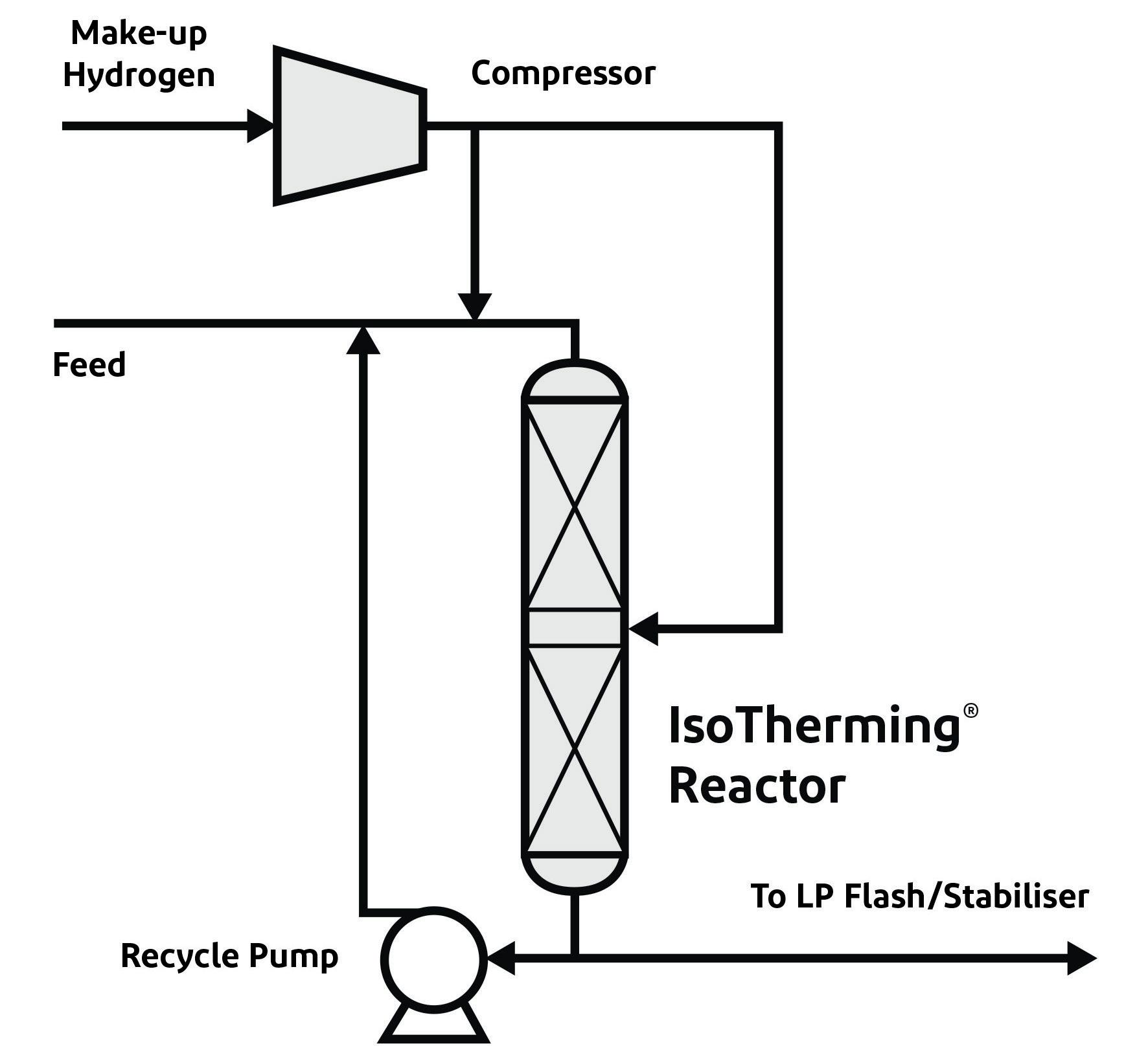
The fundamental principle of the technology is the ability to provide the hydrogen that is necessary for chemical reactions using a liquid stream, rather than a recycle gas system. The reactor feed is saturated with hydrogen, which eliminates the need for a recycle gas compressor and amine absorber. To satisfy hydrogen requirements within the reactor, additional hydrogen can be added by means of an external liquid recycle stream and/or inter-bed hydrogen injection. Feed types that have low hydrogen demand, such as kerosene, do not require an external recycle stream to satisfy hydrogen availability requirements.
Operating the reactor liquid-full also acts as a heat sink for the exothermic reactions. Thus, the reactor operates closer to isothermal conditions, which reduces uncontrolled cracking reactions and lowers the production of light ends.
The type of hydroprocessing application, product objectives, and chemical hydrogen requirements dictate optimal reactor design considerations, such as number of catalyst beds and recycle ratio. The IsoTherming reactor design is robust and has been commercially-proven to successfully provide over 160% of design chemical hydrogen consumption, while processing fluctuating feedstocks. This flexibility offers refiners the ability to
December 2022 HYDROCARBON ENGINEERING 30
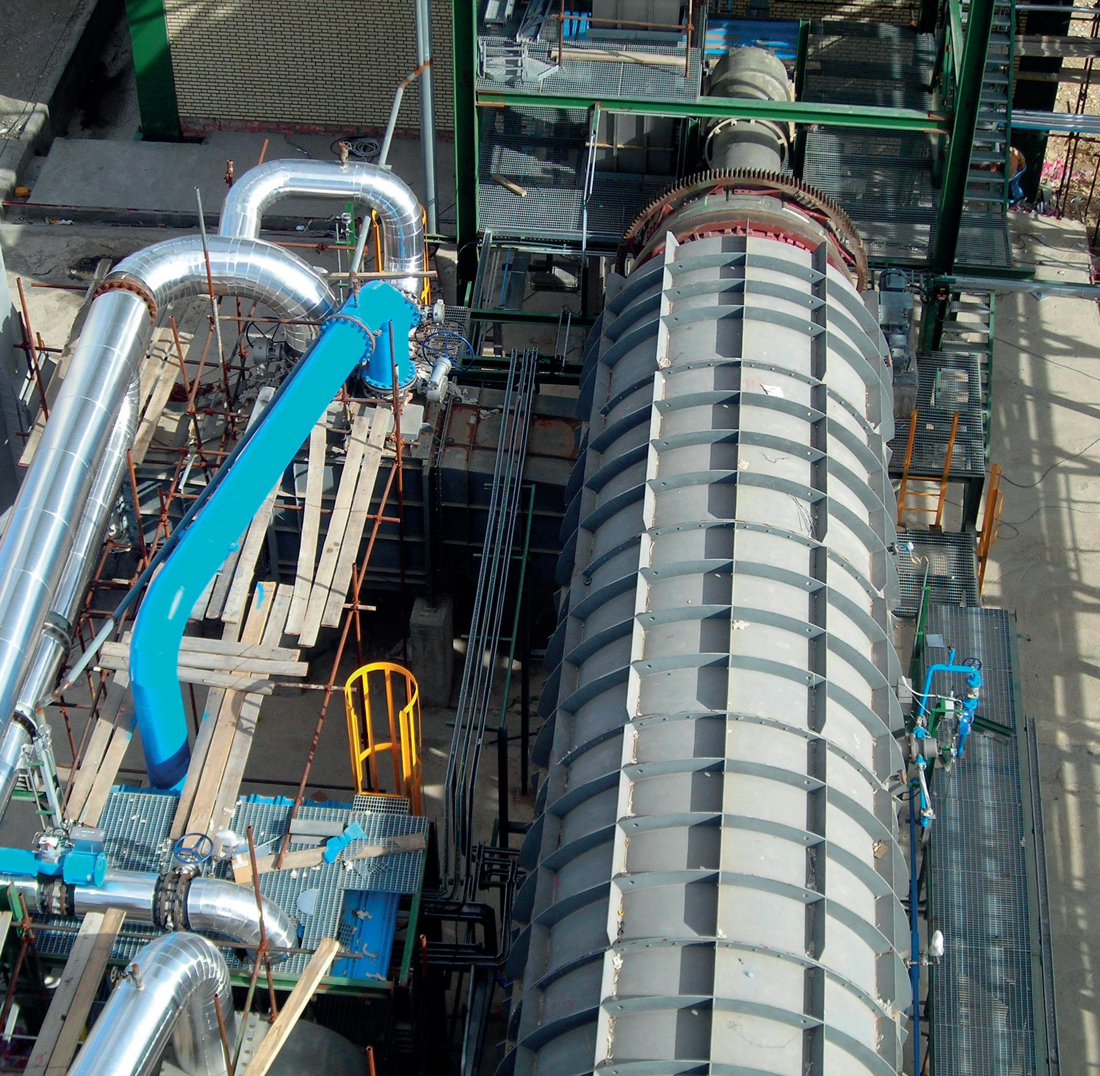
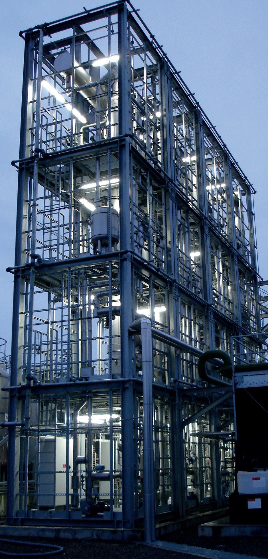
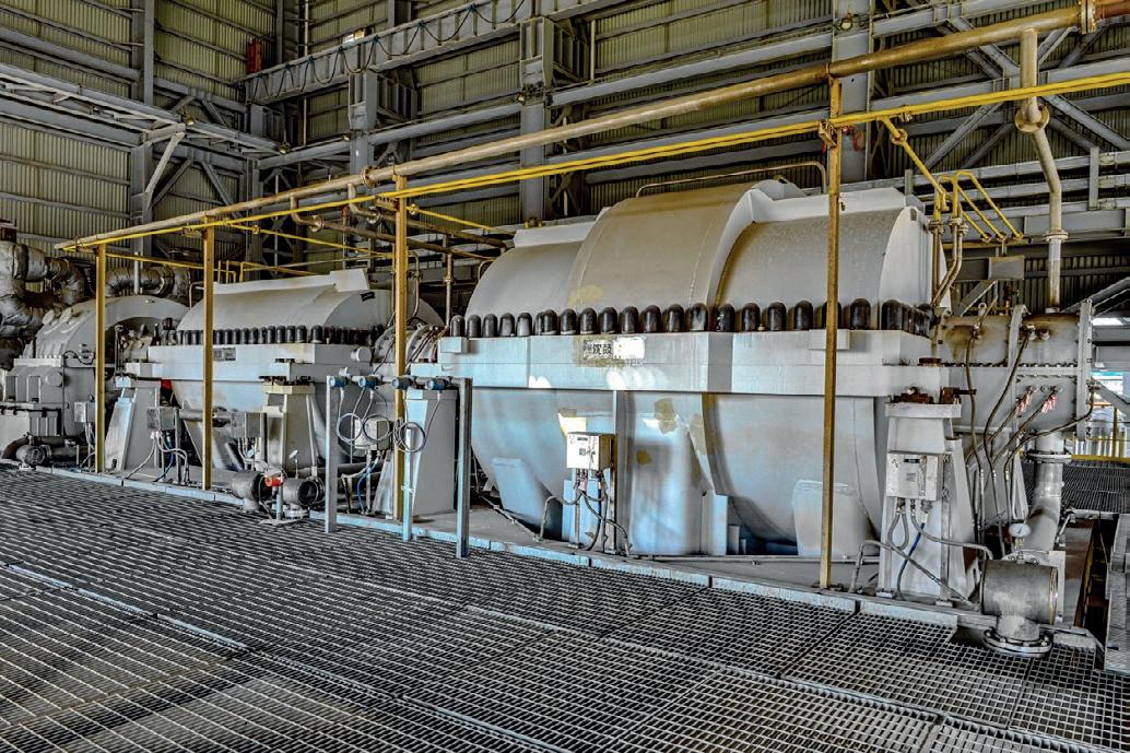
Figure 1. An IsoTherming reactor in commercial service.
Figure 2. An IsoTherming reaction zone.
process a wide variety of feeds to maximise refinery profits.

The technology currently has 29 licenses comprised of 24 grassroots units and five revamp units. There are 16 commercial installations of the technology currently in operation. The following case studies will detail how two refineries have revamped their existing hydroprocessing units.
Case study 1
The first case study is for Refinery A, located in Western Europe. Refinery A has an existing trickle bed diesel hydrotreater that lacks a recycle gas compressor. This unit currently produces ultra-low-sulfur diesel with poor cycle length. Even at reduced throughput rates, current cycle lengths range from 12 to 14 months. An evaluation by catalyst suppliers concluded that a catalyst upgrade by itself could not achieve the desired product and operating targets due to unit constraints. Therefore, the refinery decided to evaluate the option of a unit revamp for its low-pressure diesel hydrotreater unit.
Refinery A extensively studied the revamp solution with the current trickle bed technology, and compared this to a revamp solution offered by Elessent Clean Technologies with the IsoTherming technology. A full conversion of the unit to liquid phase with this technology would provide the customer with extended cycle length, as well as a return to nameplate capacity and the ability to process cracked feedstock. A summary of the key benefits can be seen in Table 1.
Feedback from Refinery A indicated that the proposed trickle bed revamp solution was more capital cost intensive and comprised a longer list of new equipment, including a new recycle gas compressor (and associated high-pressure auxiliary equipment, such as an amine absorber and heat exchangers). Even with a new recycle gas compressor, the trickle bed technology was unable to offer the same extension in cycle length at the nameplate capacity as the IsoTherming technology, and additional catalyst volume or reduced feedstock rates were required to meet a similar cycle length.
In addition to offering a low capital cost, revamping with the IsoTherming technology provides additional operating efficiency benefits to Refinery A. The feedstock under review has very high levels of hydrogen consumption and thus a high volume of heat release. Due to the energy-efficient nature of the IsoTherming technology, coupled with this high level of heat release, the feed-fired heater is only required to operate at minimum operation rates outside of start-up conditions. Even at this minimum rate, there is surplus heat after pre-heating the feed. As such, a cost/benefit analysis was conducted, and it was deemed economical to utilise the excess heat from the reaction to produce medium-pressure steam in the unit. Table 2 quantifies the high-pressure energy savings expected post-revamp with the new technology, compared against current trickle bed operation.
Based on the assumed cost values of fuel gas and steam, the revamp would save Refinery A

Hydrocarbon-engineering-IGS-corrision-in-ht-hp-webinar.indd 1 22/11/2022 13:05:43
Updated For more news visit: www.hydrocarbonengineering.com
Keep
Keep up to date with us to hear the latest downstream oil and gas news
US$1.7 million (US$51/bbl of feedstock) annually in high-pressure utilities alone. Additional savings are also expected from low-pressure utilities.
This revamp solution is not only attractive from a capital and operating cost standpoint, but it also lowers the carbon footprint of the refinery due to the reduction in combustion of fuel gas from the fired heater. Based on the normal operating duties shown in Table 2, the reduction of 5520 tpy of CO2 emissions is equivalent to the removal of over 1200 light passenger vehicles annually (based on heat content of propane of 139 million Btu and 4.6 tpy of CO2 emissions from a single light passenger vehicle). Support for the revamp of Refinery A’s diesel hydrotreater unit with the new technology continues, in anticipation of a 2025 start-up date.
Table 1. Refinery A – current operation vs IsoTherming revamp
Case study 2
The second case study is for Refinery B, located in Eastern Europe. Refinery B has an existing trickle bed diesel hydrotreater with an approximate capacity of 229 standard m3/hr (Sm3/hr), which equates to 35 000 bpd. The refinery is investigating options to reach its decarbonisation targets and optimise operating expenses, while maintaining its current capacity.
Elessent Clean Technologies worked closely with Refinery B to evaluate multiple revamp scenarios geared toward its decarbonisation and sustainable operating objectives. A comparison of the final revamp conditions compared to current operation is presented in Table 3.
Based on the assumed values of diesel and fuel gas, the revamp saves Refinery B US$1.9 million (US$53/bbl of feedstock) annually from increased diesel yield, fuel gas savings and tax savings from reduced carbon footprint of the unit.
In addition to a reduction in operating expenses and carbon footprint, the revamp cost and effort from trickle bed to the IsoTherming technology was proven to be minimal. It was confirmed that the heat exchangers and air coolers supporting the existing trickle bed unit can be utilised with the new technology, with the only additional equipment required being the reactor recycle pump and proprietary IsoTherming Reactor internals.
Table 2. Refinery A – utility comparison: current operation vs IsoTherming revamp
Normal operating charge heater duty (million kcal/hr) 4.936 1.780
% savings 64%
Fuel gas (kg/hr) 414 149
Fuel gas value (US$/yr1) 1 233 224 444 711
Steam produced (kg/hr) 10 281 Steam value (US$/yr2) 891 035
Annual net value of utility consumption/production (US$) 1 233 224 446 324
1 Based on a fuel gas value US$/million kcal of US$29.7
2 Based on steam value US$/1000 kg of US$10.3
Table 3.
Parameter
Refinery
B – current operation vs IsoTherming revamp
Current IsoTherming revamp
Diesel yield (wt%) 96.7 98.5
Additional diesel value (US$/yr1) 701 527
Fuel gas (Gcal/hr) 10.0 6.4
Fuel gas savings (US$/yr2) 1 128 325
CO2 emissions (tpy) 21 003 13 442
CO2 tax savings (US$/yr3) 39 338
Annual net value of diesel yield/fuel gas (US$) 1 869 190
1 Based on a diesel value of US$558/t, and off-gas value of US$426/t
2 Based on 11.1 Gcal/t heating value for fuel gas, and fuel gas value of US$426/t
3 Based on 2.58 t CO2/t fuel gas (CO2, SO2, NOX), and tax of fuel gas of US$150.50/t
Due to the low CAPEX required for this conversion, the calculated payback for the effort is only three years given the value provided with increased diesel yield, reduced fuel gas consumption and CO2 tax savings. Support for the revamp of Refinery B’s diesel hydrotreater unit with the technology is ongoing, as a revamp from trickle bed is anticipated in the near future.
Conclusion
The global market demand for biofuels continues to increase as mandates and renewable fuel credits are being implemented across the world. Whether mandated or not, renewable fuel production is likely on the mind of all refiners. The IsoTherming technology is well-suited to assist refiners in the production of renewable distillate range products. The liquid-full technology is capable of handling the high hydrogen consumption and temperature rise that is associated with processing lipid-based feedstocks – whether in conjunction with a petroleum-derived feedstock or in a standalone unit. It also unlocks the ability to co-process without the concern of the trickle bed’s recycle gas compressor limitations. The capital cost savings, energy efficiency and sustained catalyst life highlighted in the aforementioned case studies will also be apparent in a renewable processing application.
December 2022 HYDROCARBON ENGINEERING 32
Parameter Current IsoTherming revamp
Capacity 149 Sm3/hr 205 Sm3/hr (↑ 38%) % cracked feedstock 0% 8.1%
Feed density @ 20°C (kg/m3) 860 909 (+49 points) LHSV hr-1 0.34 0.78 Cycle length 12 – 14 months 36 months (↑ 3x) Recycle hydrogen Once through Recycle pump
Parameter Current trickle bed IsoTherming
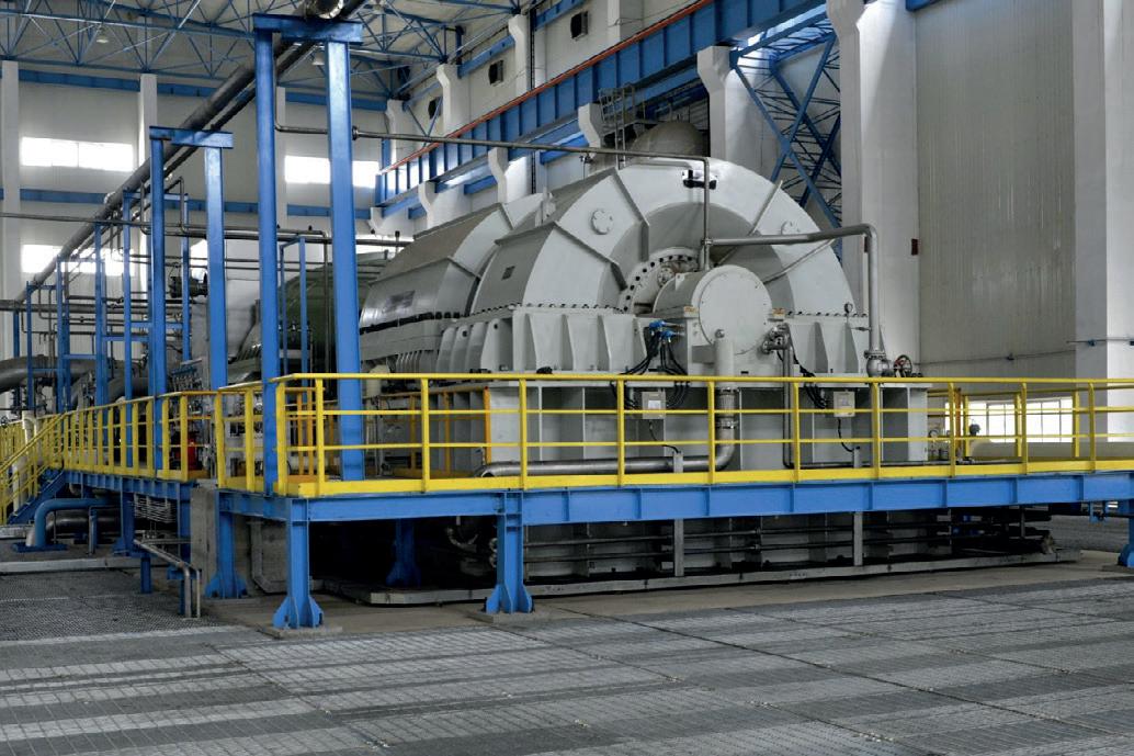
Mission critical equipment, including process vessels, towers and columns, play a major part in maintaining the uptimes and levels of production of oil and gas plants worldwide. These vessels typically operate at elevated temperatures and pressures, and are constantly subjected to a wide variety of aggressive, corrosive chemicals produced or added into the process.
One of the primary causes of process disruption is the issue of corrosion and metal wastage. There are several viable options available to address the corrosion mechanisms with a corrosion resistant alloy (CRA) barrier. The technique used to apply this CRA will predominantly be determined by the shutdown time that is available to carry out the application.
There are many different technologies that can be utilised to provide surface protection solutions for mission-critical equipment. Each technology has its advantages and
disadvantages that need to be well understood by customers so that they can make the best decision for their unique facility.

Process vessels operating at elevated temperatures and pressures represent one of the most arduous service environments and major challenges for asset owners and operators. These vessels, and those involved in the separation of oil/water and gas as it enters the process stream, are constantly subjected to a wide variety of aggressive conditions that can ultimately lead to severe internal corrosion.
Corrosion mechanisms
In the FEED stage, refineries and oil/gas processing plants are designed to provide a minimum operating life (design life). However, conditions rarely match the FEED parameters in service. Plants operate well beyond the original design life, and challenges in vessel fabrication, design and process operation
December 2022 33 HYDROCARBON ENGINEERING
Dennis Snijders, Integrated Global Services (IGS), offers solutions for process vessel corrosion protection, and highlights a project that the company carried out in the Middle East.
typically lead to higher internal corrosion rates than anticipated. This introduces the requirement for maintenance, repairs or replacement of process equipment to prevent loss of containment, as well as maintain asset integrity and process operation.
The cost of corrosion
Corrosion ultimately leads to metal wastage and a loss of shell thickness. Plant and process shutdowns caused by issues with these critical assets can quickly run up losses of tens of millions of dollars. It is reported that a 29-day turnaround at Valero’s
St. Charles refinery in the US cost US$39 million, and it was estimated that the company lost US$1.2 – 3 million/d if the turnaround went beyond its projected timeline.1
Preventing/stopping corrosion
There are a variety of solutions available on the market to help prevent the process of corrosion, including welding, various coatings, and Integrated Global Services (IGS)’ High Velocity Thermal Spray (HVTS).
Welding is a commonly-used solution in the oil and gas industry, both for rebuilding degraded areas of wall thickness and providing a corrosion-resistant alloy barrier. Welding carries some fundamental drawbacks. A common issue is distortion of the shell due to heat input during the welding process, which can further require crane support to the equipment. A high degree of stress is added into the process during welding, especially on thinner wall vessels. Additionally, the weld procedure, code or environmental conditions may require heat treatment prior to or after the application as an additional step to the repair solution.
There is also a question of time and costs. Welding is a relatively slow process with an application time of 10 – 16 ft2 (1 – 1.5 m2) per weld head per shift, and can cause additional delays in bringing the asset back into service. During a critical path period, using welding for corrosion protection can have a significant financial impact.
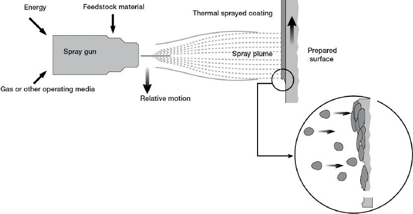
Thermal spray
Thermal spray technology has been utilised for the application of CRA since the 1980s, spraying metals that are widely used in the welding process. However, it was quickly noted that the thermal spray process itself can negatively affect the condition of the material being sprayed. The resulting cladding, when using traditional metal alloys and commercially-available thermal spray equipment, is permeable. This permeability, coupled with internal stress and a lower bond strength with the base metal, creates a path for corrosion and premature failure.
Figure
These early failures have resulted in an understandable and rather universal distrust of early iterations of commercially-available thermal spray technology. The issues with thermal spray cladding raised some important questions, including whether it was possible to eliminate the permeability, porosity and internal stress of the thermal spray applied coating, and improve bond strength.
The best solution for preventing corrosion
With corrosion causing disruption to many refineries, the industry needed a solution that could eliminate the permeability, porosity and internal stress of commercial thermal spray without compromising bond strength, delivering a robust solution similar to welding.
IGS understood this industry problem and developed its own proprietary solution – a corrosion-resistant HVTS technology. Designed to protect the base metal in highly-corrosive environments, this technology involves the simple application of a non-porous, high-nobility metal alloy.
The application process is considerably faster than welding, and no stresses are imposed on the base material during the application process. Furthermore, the process does not
December 2022 HYDROCARBON ENGINEERING 34
Figure 1. Welding repair.
2. Thermal spray application.
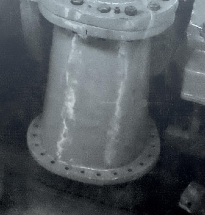
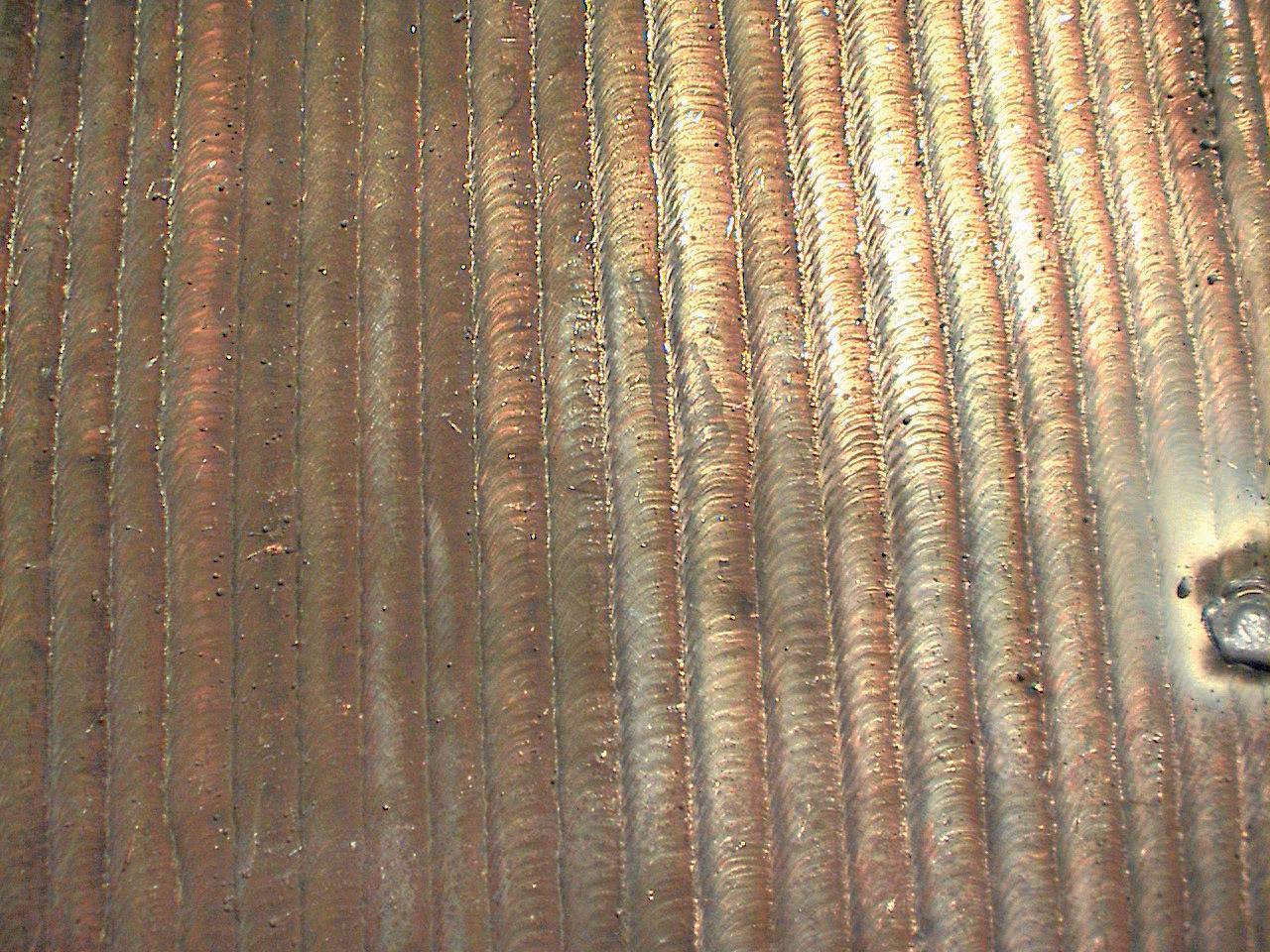
Figure 3. The 2021 inspection of HVTS applied by IGS in 2015 shows the cladding in excellent condition.
generate any dilution. The quality of the cladding remains uncompromised, and there is no potential for galvanic corrosion due to dissimilar metals.
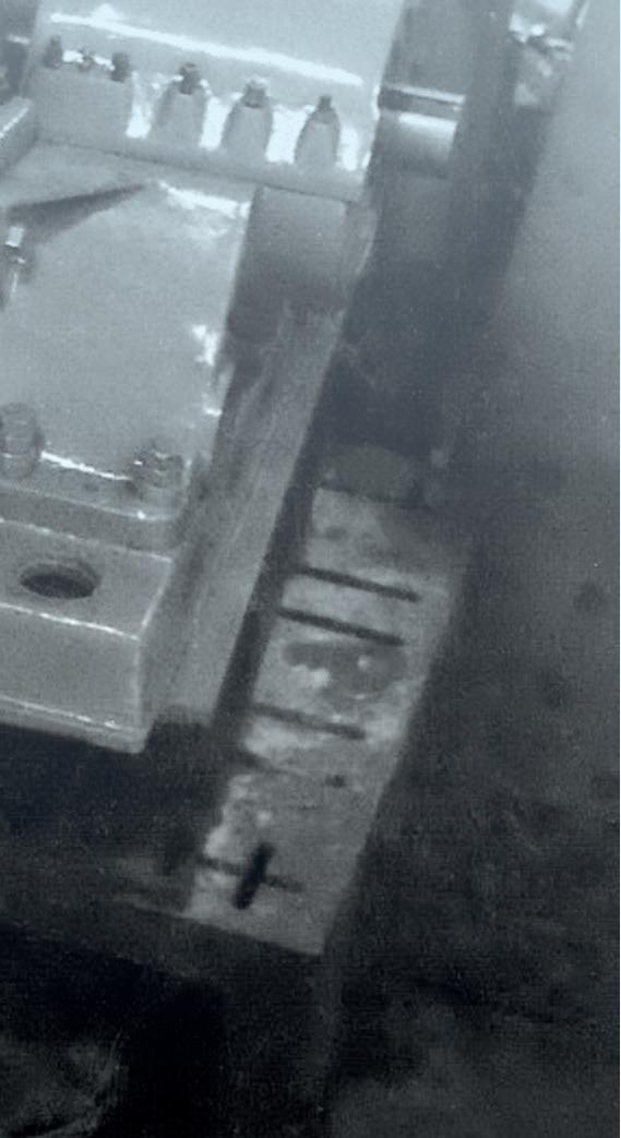
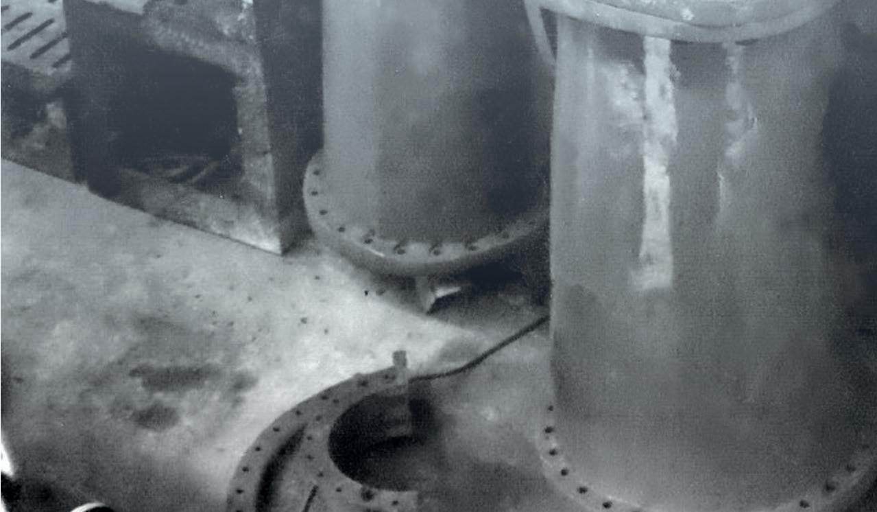
Case study: comparing solutions for amine vessel corrosion in the Middle East
In 2015, a gas plant in the Middle East identified internal corrosion in two of its amine process columns and contracted IGS to apply HVTS alloy cladding to protect the base metal. The cladding was applied, and in 2016 the plant went out to public tender for the completion of a similar work scope on six more columns. The plant decided to use a local thermal spray contractor on a cost basis which involved using a conventional low velocity thermal spray process technology.
Amine vessel corrosion mechanisms
In the amine system, most of the corrosion is related to acid gas breakout and the subsequent attack of the metal surface, usually at elevated temperatures. Since corrosion is a chemical reaction, high temperatures always accelerate corrosion activity because reactions occur faster and more aggressively at higher temperatures.
There are often several factors that contribute to failure by corrosion. Statistics show that almost 50% of corrosion incidents occur in the hottest part of the plant: the reboiler and the bottom of the amine regenerator. In amine plants, most
corrosion is related to hydrogen sulfide (H2S) or carbon dioxide (CO2) breakout, and the subsequent attack of the metal surfaces – usually in areas of elevated temperature or a high pressure drop (leading to condensation).
Further potential corrosion mechanisms exist in amine columns. In the lower section of a regenerator, for example, carbon steel surfaces not wetted by the amine solution may be attacked by water vapour and the formation of carbonic acid. Acid gas ratio, choice of amine (DEA, MEA, MDEA, DGA, AGR, etc), contaminants, two-phase flow, flashing, high velocities, vessel design and insulation are all contributing factors. Pitting, crevice corrosion, flow-enhanced corrosion and general corrosion loss are frequent problems.
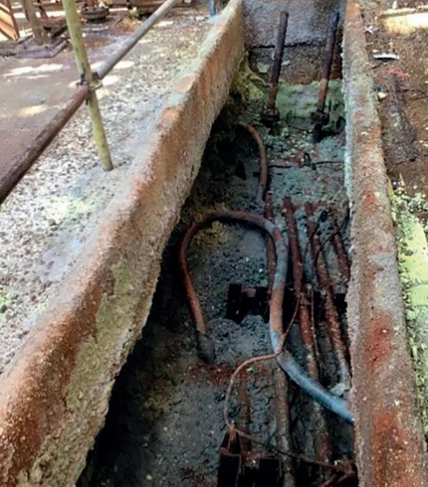
In this case, the plant in the Middle East conducted a planned inspection and noticed pitting in its amine process columns, which would eventually lead to failure if left untreated, and potentially cost the plant millions of dollars to replace the columns.
The solution
Some mechanical options include the installation of temporary clamps and plugs, vessel section replacement, and the application of internal weld overlay. The time required for these, together with the post weld heat treatment (PWHT) needed to remove heat affected zones (HAZ) and structural support considerations, often demand extended turnaround or shutdown schedules and associated production losses. Table 1.
December 2022 HYDROCARBON ENGINEERING 35
Comparison of corrosion protection methods HVTS Welding Organic coating Corrosion resistance High High Medium (temperature and % concentration dependent) Erosion resistance High Medium (depending on alloy) Medium (material dependent) Typical alloys utilised Modified hastelloy and monel alloys 316, 625, 622, 52, monel, hastelloy with Fe dilution N/A Bond Mechanical and chemical (>35 MPa) Metallurgical Mechanical and chemical (> 15 MPa) Heat treatment before/after application No Yes (or HAZ becomes weak corrosion resistance area) No Dilution into base metal No Yes No HAZ No Yes No Stress/distortion of base material No Yes No Application speed 32 – 64 ft2 (3 – 6 m2) per shift/machine 5 – 21 ft2 (0.5 – 2 m2) per shift/machine 53 – 107 ft2 (5 – 10 m2) per shift/gun and variable curing time Repairability Blast prep, build-up and/or local reapplication Blast prep, grind and re-weld if not cracked/contaminated Blast, surface preparation and reapplication Durability Mechanically tough and resistant to high temperatures Mechanically tough Vulnerable to mechanical and heat damage Steam-out resistance Yes Yes No Thermal resistance > 932°F (500°C) > 932°F (500°C) < 284°F (140°C) Curing requirements Not required Not required Up to five days Application requirements Minimum environmental controls Minimum environmental controls Strict environmental controls (including temperature, humidity, surface salts, amine bloom, surface release) External inspection capability during normal operation Yes Yes No
Temperature and chemical compatibility limitations have prevented the effective use of organic coatings. Due to the nature of the sour feed, loss of containment poses a major safety and environmental risk.
The gas plant in the Middle East chose to use an alloy cladding solution to fix the issue of corrosion in its amine process columns. This solution provides the same benefits as a high-nobility weld overlay corrosion barrier, with several additional advantages including no HAZ or requirement for PWHT; no distortion of base materials; and a rapid application speed. The following section will discuss the results of the application of HVTS to two of the columns vs the low velocity thermal spray applied by a local contractor to six of the columns in 2016.
The inspections: high velocity vs low velocity thermal sprays
The first inspection of the two columns protected by HVTS took place in 2018, with no signs of further corrosion. The protective cladding was in excellent, as-applied condition. Further inspection by the plant’s senior corrosion engineer in November 2021 revealed a significant contrast between the two columns sprayed with HVTS in 2015 and the other columns applied with the low velocity thermal spray in 2016. The HVTS
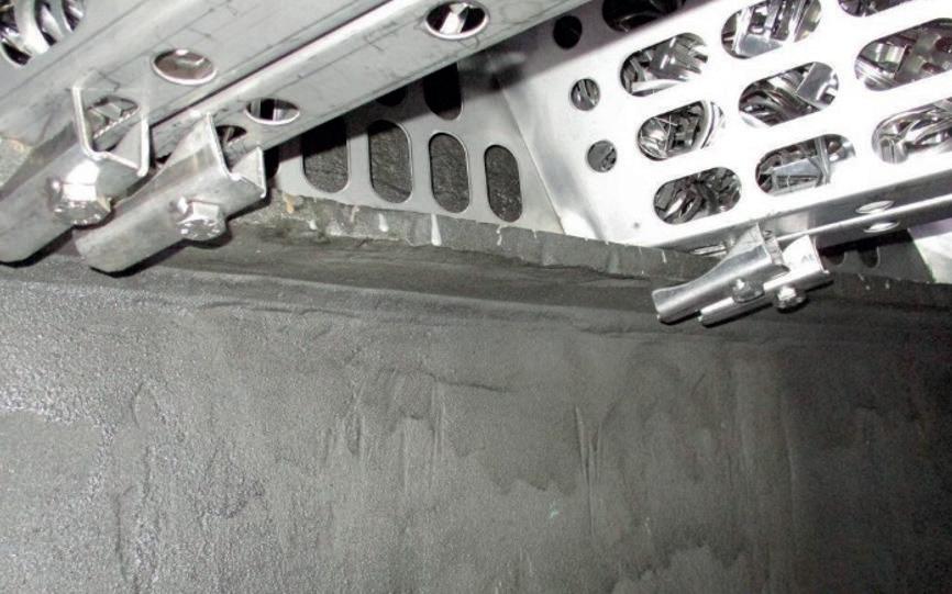
was still in excellent condition, with no signs of cracking or failure. However, the other columns sprayed with the low velocity thermal spray showed extreme signs of breakdown of the applied cladding and corrosion of the substrate, with the wall thickness loss threatening to exceed its maximum corrosion allowance.
If left, the ongoing corrosion could result in an unplanned shutdown, potentially costing millions of dollars in lost revenue. In the best-case scenario, the column would need to be stripped of the remaining cladding, undergo mechanical repairs (which is both costly and time consuming), and then be protected with a long-lasting HVTS.
The science
This scenario is a common occurrence at many oil and gas plants, refineries and petrochemical sites. Although the initial cost is often far less, the long-term expense outweighs the short-term savings. To understand why the low velocity system failed, it is important to understand the science behind various types of materials and application methodology.
Material modification
Standard welding alloys are unsuitable materials for thermal spray application in critical internal process equipment, as the cladding particles form oxides on their surface in flight, creating a fundamental weakness in the microstructure and permeability.

True high velocity application technology
HVTS conveyance technologies atomise the bespoke wire feedstock in a supersonic gas stream, producing a cladding that consists of flat and tightly-packed, micro-sized particles. Conventionally-available thermal spray application systems cannot produce equivalent particle sizes – they have a more open microstructure and do not impart sufficient energy to flatten the particles that are inherently highly stressed. These shortcomings lead to premature failure due to permeation from microstructural weaknesses and cracking of the coating.
Conclusion
Figure 4. The 2021 inspection of the six columns coated with a low velocity thermal spray shows severe corrosion and risk of failure.

The high cost of corrosion for refineries around the world emphasises the importance of asset maintenance and protecting process materials from degradation and loss of performance. Unplanned shutdowns can have a significant financial impact in terms of lost productivity and emergency remedial works.
There are several solutions available on the market today, namely weld metal overlay (WMO), which is a reliable albeit time consuming and costly method. Thermal spray is another solution which, in theory, is a better alternative to WMO but can lead to premature failure. HVTS is the next evolution of thermal spray coatings which provides reliable, long-term protection from corrosion.
As asset failure continues to be a costly problem for the downstream oil and gas industry. It is crucial that preventative measures are taken to improve asset life, reduce downtime, and deliver significant savings.
Reference
1. ‘Shutdown & Turnaround of Refineries’, Opus Kinetic, (September 2017), https://www.opuskinetic.com/2017/09/shutdownturnaround-of-refineries/
December 2022 HYDROCARBON ENGINEERING 36
Figure 5. HVTS application.
Anumber of different types of heat exchangers are used in the petrochemical and chemical industry to add or remove energy from a process. These include coolers, condensers, evaporators, preheaters, reheaters, reboilers, and air coolers.
The transfer of energy can happen between two different process fluids, or in cases where energy needs to be added to the system, an external heating source such as steam can be used to heat the fluid. If, on the other hand, energy needs to be removed from the system, this can be dissipated using an external cooling source such as water or air.

Heat exchangers are categorised depending on the type of process fluid, physical changes happening to such fluid, and whether a cooling or heating medium is being used. However, the overall transfer of energy concept remains.
For example, in general, when the fluids on both sides of the metal are single-phase and are both process streams, the equipment is simply called a heat exchanger. However, if the aim is to reduce the temperature of a process stream using water or air, this equipment is known as a cooler. Condensers, on the other hand, use cooling water or air as the cooling media. In this case, the process fluid on the other side of the tube is a vapour stream that condensates due to the temperature drop that it is being exposed to. Finally, heaters and reboilers carry a process fluid on one side of the tube, and steam or hot oil on the other side of the tube, which is used to bring the process fluid up to the desired temperature.1
Given the complexity of the application, choosing the right material for the construction of heat transfer equipment is important for reliable operations. The selected grade must offer
December 2022 37 HYDROCARBON ENGINEERING
Karen Picker, Alleima, USA, explains the thought that goes into selecting the optimum material for heat exchangers.
adequate corrosion resistance combined with mechanical and physical properties that are able to withstand variations in temperature, pressure, and the aggressiveness of the process fluid. Some of the more common corrosion issues that cause premature failures in heat exchangers are general or uniform corrosion, pitting, crevice, under deposit, and erosion corrosion.
General corrosion
General corrosion takes place when the material is exposed to strongly acidic or alkaline solutions and a uniform mass loss per unit surface area occurs. General corrosion is expressed as mean metal loss per unit time in millimeters per year (mm/yr) or milli-inch per year (mpy).
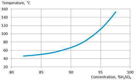
Isocorrosion curves are typically used to represent the resistance of the metal to the intended service conditions. For example, to select material for a heat exchanger in sulfuric acid (H2SO4) service with 93 – 98.5% concentration, operating temperatures of between 60 – 120°C in the shell side, and cooling water at temperatures between 25 – 45 °C in the tube side, the isocorrosion curve shown in Figure 1 offers good guidance to start material selection based on the shell side process conditions.
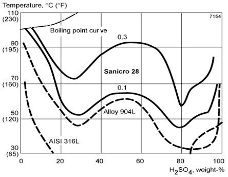
Figure 1. Isocorrosion diagram for Sanicro 28 in. deaerated sulfuric acid with corrosion rates of 0.1 and 0.3 mm/yr. For alloy 904L and AISI 316L, the curves represent a 0.1 mm/yr corrosion rate. Table 1.
This figure shows the isocorrosion curve of three different grades in H2SO4. Sanicro® 28 is shown with two curves representing 0.1 and 0.3 mm/yr corrosion rates. Alloys 316L and 904L are shown with dashed curves, representing a 0.1 mm/yr corrosion rate. This isocorrosion graph suggests that Sanicro 28 performs better at different temperatures and concentrations of H2SO4. However, should one of these materials be used under the process conditions presented in this case, the high concentrations and temperature of the acid will cause premature failure of the bundle.
For H2SO4 services with high concentrations (> 90%) and high temperatures, silicon-based alloys such as Alleima® SX are a better choice, as shown in Figure 2. When selecting material, it is important to characterise the entire system and take into consideration contaminants and the corrosivity of both the shell side and tube side. In this instance, the cooling media used in the tube side is water. Depending on the level of chlorides present in this water, silicon-based alloys might not be the right choice, since their pitting resistance is not sufficient if the chloride content in the water is higher than 100 ppm.
Pitting corrosion
Pitting corrosion is a type of localised attack on a small area of the metal surface due to localised breakdown of the passive film, usually caused by the presence of chlorides. Pitting corrosion is most likely to initiate at weak points such as weld heat affected zones or at surface defects and inclusions. Controlling the concentration of aggressive ions such as chlorides and pH, and selecting alloys with the right chemical composition, are key to addressing or preventing pitting corrosion.
Seawater coolers used in the process industry, or gasifiers used in the LNG industry, are examples of the types of equipment that are commonly affected by this form of corrosion. Seawater contains large amounts of sodium chloride (NaCl) and solid particles, such as sand and organic solids. As a result, it is more likely to induce pitting corrosion in the metal. However, even equipment that uses freshwater or city water can be prone to this issue.
When selecting material for chloride-bearing environments, the Pitting Resistance Equivalent Number (PREN) of each grade can be compared to ease the decision making process. The PREN is calculated using equation 1, which relates the alloy’s chromium (Cr), molybdenum (Mo), and nitrogen (N) content, with its resistance to pitting corrosion. This number is used for
December 2022 HYDROCARBON ENGINEERING 38
Minimum PREN values for commonly used Alleima stainless steel grades Alleima Grade PRE Cr Mo N 304L 18 18 316L 24 17.5 2.1 Alloy 825 28 20 2.5 SAF 2205 35 22 3.2 0.18 Sanicro 28 39 27 3.5 254 SMO* 43 20 6.1 0.2 SAF 2507 43 25 4 0.3 SAF 2707 HD 49 27 4.8 0.4 Sanicro 35 53 27 6.5 0.3 *254 SMO
is a trademark owned by Outokumpu OY
Figure 2. Isocorrosion diagram, 0.1 mm/yr, for Alleima SX base in concentrated H2SO4 at static conditions.

an approximate ranking of stainless steels in chloride-bearing environments, as shown in Table 1. The alloys with the higher PREN are expected to have a higher resistance to pitting corrosion when exposed to the same environment.2 However, the alloy’s mechanical properties and the expected operating temperatures of the equipment must also be considered.
PREN = %Cr + 3.3%Mo + 16%N (1)
For example, duplex stainless steels (DSS) are a great choice for seawater cooling applications in the process industry, due to their excellent mechanical properties (which make them more resistant to erosion corrosion), and their high PREN (which indicates their high pitting resistance). Moreover, the operating temperatures of heat transfer equipment in the process industry are typically well within the temperatures that DSSs are designed for (-50 – 280˚C).
However, in the case of LNG gasifiers, for example, this family of alloys is not a good fit due to the cryogenic temperatures that the application sees. In this case, the new grade programme for LNG from Alleima, including Sanicro® 35 (a new family of super austenitic [highly-alloyed] seamless stainless tube with 5 – 7% Mo) would be the right material choice due to superior corrosion resistance and high mechanical strength –even at cryogenic temperatures.
Another way to select the most appropriate material for heat exchangers based on the equipment operating temperature is to evaluate grades by their Critical Pitting Temperature (CPT). CPT is the temperature determined through accelerated laboratory testing such as ASTM G48 (6% FeCl3 solution), at which a material is expected to initiate pitting corrosion. CPT values are specific to the environment and the test method used. When comparing alloys, it is important to note the environment in which the test was performed. In addition to pitting corrosion, the corrosive seawater used in this LNG application usually presents the challenge of crevice corrosion in the tube-to-tubesheet section of the equipment. However, these grades can substantially extend the service life of vaporisers, without the need to upgrade the entire equipment to high nickel grades such as Alloy C-276.
Crevice and under-deposit corrosion
Crevice corrosion occurs due to oxygen depletion in the localised environment that prevents the re-passivation of the alloy and promotes the formation of a corrosive cell. The
difference between this and pitting corrosion is that crevice corrosion, as the name suggests, will always initiate at crevices found in the equipment, due to design limitations or flaws.
For shell and tube heat exchangers, the weak point is the tube-to-tubesheet interface on the shell side, which happens to be the problem area for LNG vaporisers. Another form of crevice corrosion found in heat exchangers is one that forms under deposits. Salt deposits and fouling are common causes of the failure of heat exchanger tubes. Ammonium chloride (NH4Cl) and sodium chloride (NaCl) salt precipitation are common in refinery processes. While the best way to address salt deposits is to prevent salt formation in the first place, this is not always achievable, as this requires adjustments to the process operating parameters, which may impact the overall efficiency of the process. Generally, a higher alloyed grade will have better resistance to under-deposit corrosion, and similarly to pitting corrosion.
One test that can be used to indicate the crevice corrosion resistance of different alloys is ASTM G48 methods D and F. These methods help to determine the critical crevice temperature (CCT) of the alloy when exposed to a 6% FeCl3 solution utilising a crevice former. Method D, which is intended for testing nickel alloys, utilises 0.28 newton-meter (Nm) force applied for 72 hours. Method F, as designed for the testing of stainless-steel grades, requires the use of 1.58 Nm force for 24 hours. Figure 3 shows a comparison of the CCT of different alloys from 6Mo grades to high nickel alloys in the two test methods. Both tests demonstrate how the high-alloyed super austenitic grade Sanicro 35 has superior performance in crevice corrosion to that of high-nickel grade Alloy 625, and similar performance to Alloy C-276.
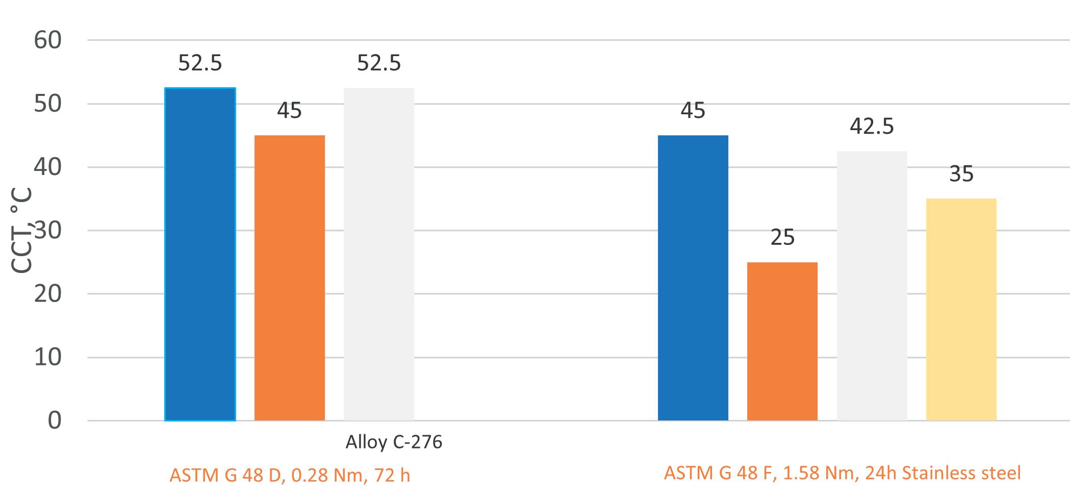
Advancing through materials technology
Heat transfer equipment is instrumental in the petrochemical and chemical process industry. A significant part of its reliability depends on proper material selection for the intended service conditions. When selecting material, it is important to take each piece of the puzzle or, in this case, the process streams, and analyse how their characteristics will impact the equipment’s performance in service.
The very first step of the process includes evaluating whether the material of choice is resistant to the general service that the equipment will be used in (i.e. sulfuric acid, nitric acid, or hydrocarbons). However, the material selection process does not stop there. The material selector must also account for the possible causes of localised corrosion. While some of the issues can be prevented or addressed through design and operating parameter adjustments, these options are not always feasible. Selecting higher alloyed materials with proven increased corrosion resistance is the logical approach. Standardised tests, isocorrosion curves, and innovative material solutions exist to help ease the process.
References
1. ‘Effectively Design Shell-and-Tube Heat Exchangers’, Chemical Engineering Progress, (February 1998).
2. Sandvik Steel Corrosion Handbook: Stainless Steel, Sandviken, Ab Sandvik Steel, (1999).
December 2022 HYDROCARBON ENGINEERING 40
Figure 3. Comparison of CCT of different alloys in ASTM G48 - D, F.
There are many different types of heat exchangers on the market today, but the traditional go-to tubular option for the process industry is the Tubular Exchanger Manufacturers Association (TEMA)-style shell and tube. Shell and tube exchangers are versatile in that they are capable of handling a wide range of process conditions in an economical way. Additionally, due to the fact that they have been around for more than a century, they are well known and ubiquitous in most plants. However, there are cases where another exchanger type, such as a hairpin (double pipe or multitube) heat exchanger, is a more efficient, cost-effective option.
In simple terms, a hairpin exchanger is a long, skinny, single-pass shell and tube heat exchanger that has been folded in half, giving it a hairpin configuration. All connections, shell side and tube side inlet and outlet, are located at the front end

of the exchanger, and a bonnet covers the U-bend end of the exchanger. While a conventional shell and tube exchanger bundle is removed from the front end of the exchanger, the bundle of a hairpin exchanger is removed from the back end of the exchanger by first disconnecting the bolting on the front end of the exchanger, then removing the bolts connecting the bonnet on the back end of the exchanger, and finally detaching the bundle.
There are numerous reasons for considering a hairpin heat exchanger rather than a conventional shell and tube. A long-held paradigm exists that hairpins are exclusively for small surface area requirements with small shell diameters. For many years, this translated into a preconceived notion that hairpins should only be specified when the surface area required is 500 ft2 or less. Anything larger should be specified as a shell and tube. This rule of thumb is long outdated, and hairpin
December 2022 41 HYDROCARBON ENGINEERING
Byron Black, Koch Engineered Solutions, USA, details the reasons for choosing a hairpin heat exchanger.
heat exchangers are now designed and sold with shell diameters up to – and even exceeding – 36 in., and surface areas in excess of 10 000 ft2. It is the process conditions and
unique mechanical features of the hairpin that dictate when one should be used, rather than the required surface area.

As the old guidelines are no longer valid, designers should question when a hairpin should be considered over a conventional shell and tube. The answer can be broken down into two categories: process optimisation and mechanical integrity.
Process optimisation
Figure 1. Cutaway showing details of a hairpin heat exchanger.
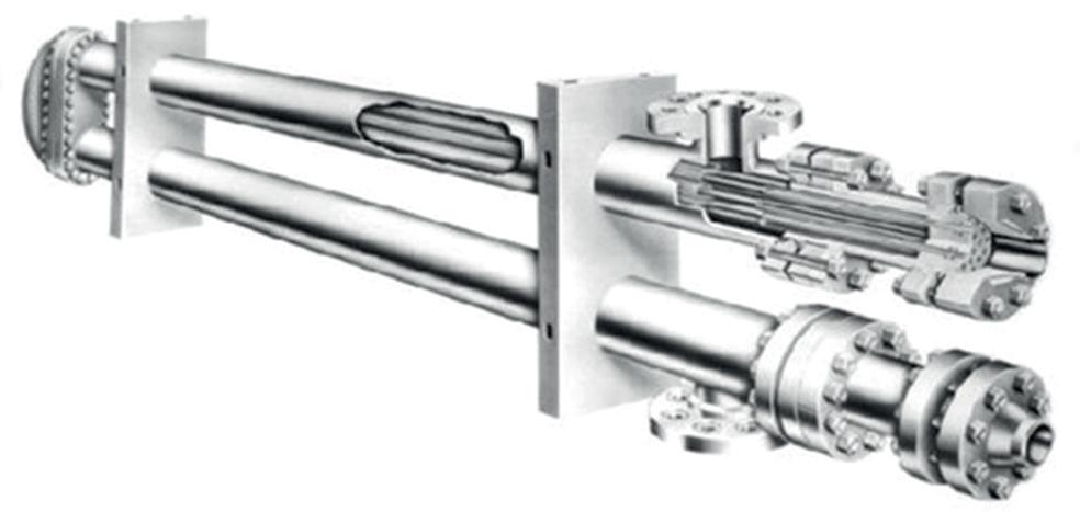
Many heat exchanger applications, such as feed-to-effluent or lean-to-rich applications, are geared towards maximising heat recovery. The desire is for the outlet temperature of one stream to get as close as possible to the inlet temperature of the other stream, which is also known as the approach temperature. This often results in a temperature cross, which occurs when the outlet temperature of cold stream is higher than the outlet temperature of the hot stream. In other words, the temperatures of the hot stream and the cold stream cross inside the exchanger at some point.
The optimal way to handle a temperature cross is with true counter-current flow, which is defined as having the shell side and tube side fluids moving in opposite directions of each other through the exchanger. Counter-current flow maximises the temperature difference between the streams through the entire length of the heat exchanger.
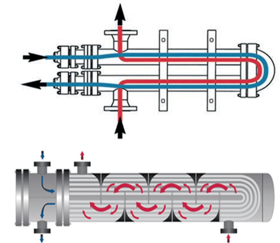
In a conventional shell and tube heat exchanger design, multiple tube side passes are typically employed, resulting in a combination of co-current and counter-current passes with the shell side fluid. In this arrangement, multiple shells in series are typically required to achieve the temperature cross by avoiding a temperature cross in any single exchanger.
Figure 2. Top: counter-current flow hairpin.
Bottom: conventional shell and tube with counter-current/co-current arrangement.
A counter-current flow arrangement is also achieved in a TEMA ‘F’ style shell, which employs a longitudinal baffle on the shell side, effectively dividing the shell side in half. By routing the shell side flow through two passes instead of one, counter-current flow can be achieved in the exchanger. However, in order to prevent bypass of the shell side fluid from the first shell pass to the second shell pass, the use of seal strips to seal the long baffle to the shell ID is required. As these components are made from a thin metal, the required removal and reinsertion of the bundle for cleaning and maintenance can lead to damage of the seal strips over time. This results in shell side fluid bypass, which can significantly degrade the performance of the heat exchanger. For this reason, the use of TEMA ‘F’ shells is not allowed in many plants.
As a hairpin exchanger matches a single shell side pass with a single tube side pass, counter-current flow is achieved, maximising the temperature efficiency without requiring multiple shells or a TEMA ‘F’ style shell.
In addition to counter-current flow, hairpin vendors often have tools to optimise the design that can increase the heat transfer coefficient, reduce shell side pressure drop, and eliminate flow-induced vibration. These include:
n Low pressure drop tube supports.
n Longitudinal fintubes.
n Various tube inserts.
n TWISTED TUBE® Heat Exchanger tubes.
Bottom: TWISTED TUBE® Heat Exchanger tubes.
Longitudinal finned tubes are utilised in applications that are shell side controlled, meaning that the shell side heat
December 2022 HYDROCARBON ENGINEERING 42
Figure 3. Top and middle: tube inserts.
transfer coefficient is much lower than the tube side heat transfer coefficient and thus controls the design of the exchanger. Adding fins increases the surface area to compensate for the low coefficient.
Tube inserts can be used to enhance the tube side heat transfer coefficient either by inducing swirl flow for high viscosity or vaporising fluids, or by blocking flow area to increase velocity.
TWISTED TUBE® Heat Exchanger tubes act in a similar way to a swirl flow type insert on the tube side of the heat exchanger, thus increasing the tube side coefficient, while the shell side generally flows in a longitudinal, interrupted swirl flow path.
Mechanical integrity
The most significant differences between a hairpin heat exchanger and a conventional shell and tube are the configuration and available closure technologies. The configuration of a hairpin provides a number of advantages over that of a conventional shell and tube, such as:
n Large radius U-bends allow for tube side cleaning and the ability to handle the thermal expansion from large
tube side temperature differences, unlike the much smaller U-bend radii of a U-tube style shell and tube exchanger.
n Tube side and shell side nozzles are on the same end of the exchanger, which not only simplifies piping, but also reduces thermal stresses on the shell side nozzles in the event of expansion or contraction of the shell.
Closure technologies for hairpins differ as compared to the various TEMA designations and result in these advantages:
n Separate, independent terminal tube side and shell side closures address applications with high terminal temperature differences and/or cyclic conditions resulting in thermal shock. These separate closures result in smaller flanges, thinner tubesheets and smaller bolts. This is a significant advantage in high-pressure applications.
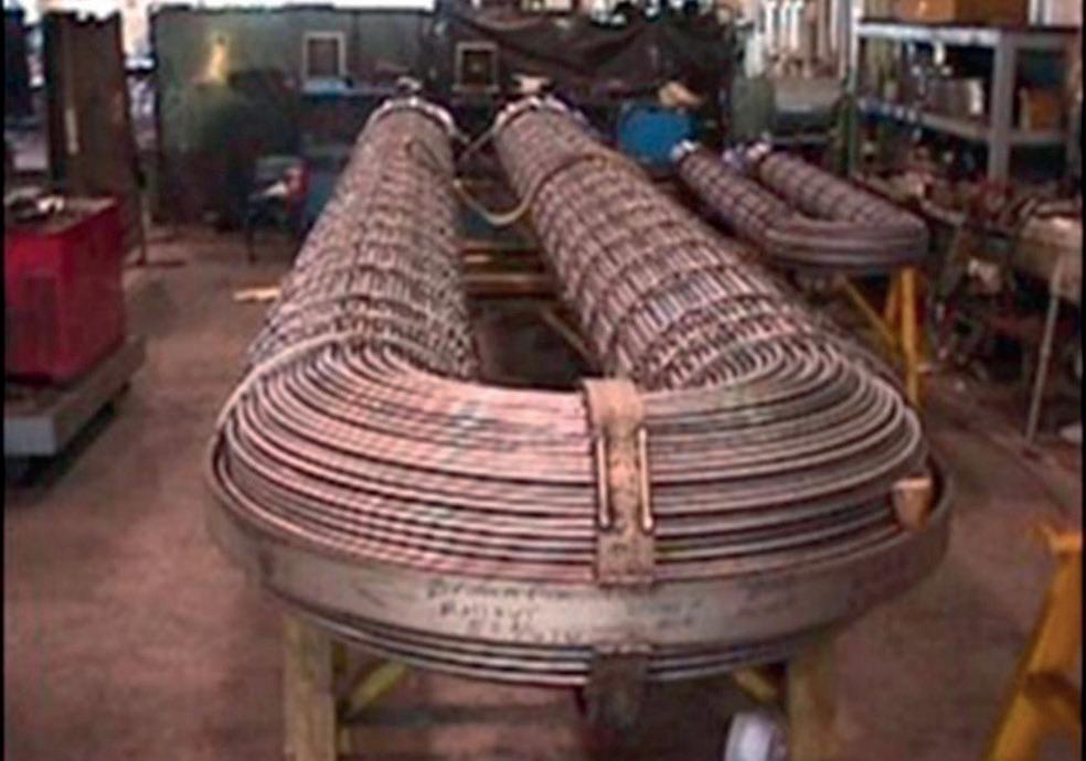
n External bolting: all bolting on a hairpin heat exchanger is external and can be tightened while the exchanger is in operation. TEMA-style floating head designs use internal bolting that comes in contact with the shell side fluid, and cannot be tightened unless the tube bundle is pulled or the floating head cover removed – both of which require the process to be shut down.
n The return bonnet closure is a compact through-bolted design, allowing for visual inspection of the shell side condition of the U-bends without removing the tube bundle or disconnecting the piping.
n High-pressure closure technology: the closure technologies offered by various hairpin vendors are unique to each vendor. However, each typically has a high-pressure closure offering. Although TEMA-style closures are often limited to pressures of below 3000 psi, hairpin closure designs have been used for pressures of up to 11 000 psi. This is particularly applicable to offshore well stream heaters as oil and gas producers seek to harvest reserves in deeper waters.
Another point to consider is that, unlike TEMA, there is no standard that dictates the model designations, nomenclature or closure types for hairpin heat exchangers, so it is recommended that users do their due diligence on the closure technologies being offered. For example, through bolting vs studs, external split rings vs internal, and separated head vs single bolted closures are all things to consider.
Conclusion
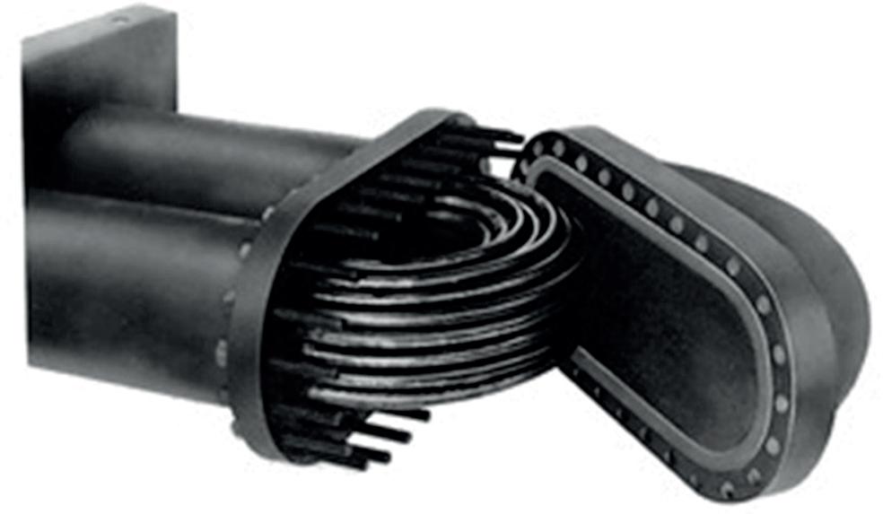
For hairpin heat exchangers, the industry standards include API 663, ISO 12212 and PIP VESHP001. Many manufacturers also have their own standards, which can be requested to ensure that they are suitable for the particular application in mind. In summary, operators should consider a hairpin when one or more of the following conditions exist:
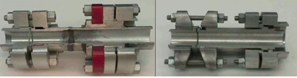
n A temperature cross or a close temperature approach is desired.
n High-pressure tube side conditions.
n Cyclic or thermal shock conditions are present.
n High terminal temperature differences exist.
n Operators wish to avoid the use of an expansion joint.
Figure
Bottom
Bottom
n Ability to clean U-tubes is required.
n All external bolting is desired.
n An augmentation device would improve heat transfer or reduce pressure drop.
December 2022 HYDROCARBON ENGINEERING 44
Figure 4. Hairpin bundle with large radius U-bends.
5. Top: removable bonnet.
left: external split ring closure design.
right: internal split ring closure design.
In energy and chemical processing, productivity and profitability are directly tied to water and energy efficiency. Heat exchanger performance is one key component behind ensuring efficiency. Industrial businesses can manage their heat exchanger performance more effectively with digital diagnostic tools and data-driven visibility.
Chemical processors and energy companies constantly strive to operate safely and sustainably while meeting productivity and profitability goals. One way to achieve these objectives in tandem is to ensure that equipment is well maintained so that it can operate efficiently with minimal downtime. Although maintenance downtime and costs are unavoidable, companies can detect anomalies by
closely monitoring performance data and acting before situations escalate.
Advancements in digital technology are enabling companies to gain better visibility into their operations, including asset performance and operations efficiency. Using predictive analytics and other data-driven tools, companies can mitigate the loss of production, avoid unscheduled downtime, and ultimately improve business outcomes.
Water systems are a prime example of where companies can integrate digital technology to optimise their daily operations. Cooling water systems are an integral part of the production process, and yet the heat exchangers that utilise this process are often monitored manually or not at all, typically with less scrutiny than other critical equipment.

December 2022 45 HYDROCARBON ENGINEERING
Tom Starr, Tommy Chen and Anupam Prakash, Nalco Water, an Ecolab Company, discuss how to drive productivity and profitability with digitally-enabled insights.
Often, this is due to a lack of readily-available data, which makes predictive maintenance (such as cleaning or retubing a heat exchanger) challenging to track and manage.
To address these challenges, Nalco Water, an Ecolab Company, offers a holistic approach that combines
continuous data acquisition with digital technology. Specifically, Nalco Water’s OMNITM Heat Exchanger Reliability program, powered by the ECOLAB3DTM intelligence platform, leverages IoT data and advanced analytics to continuously measure heat exchanger performance.

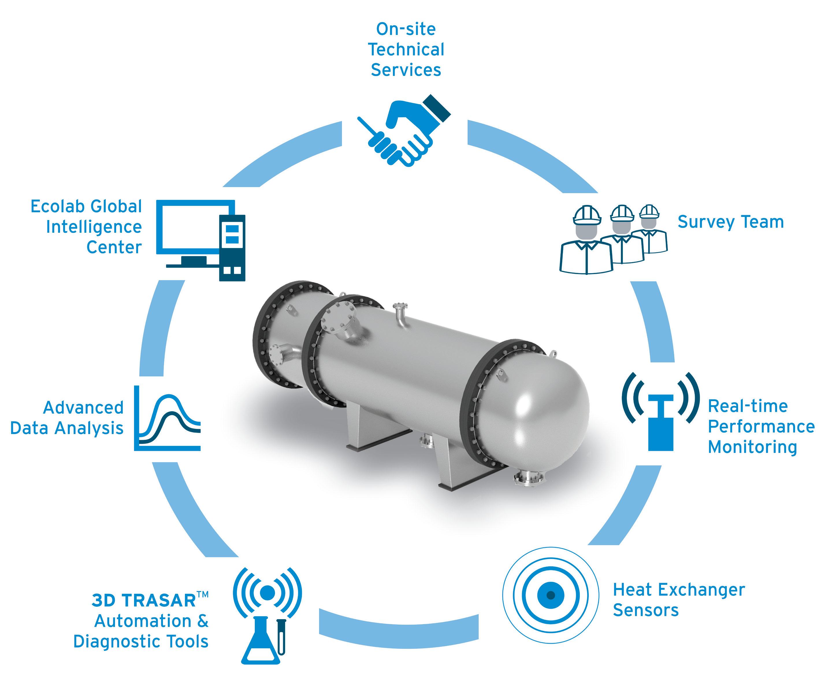
To implement OMNI Heat Exchanger Reliability, the teams at Nalco Water survey the full plant strategically with various survey frequencies on different heat exchangers, according to their situations. A stress profile of system heat exchangers is created with a comprehensive flow and temperature survey. The survey provides a snapshot of heat exchanger stresses and helps to identify critical exchangers. Then, using non-invasive sensors and proprietary diagnostic tools, Nalco Water provides continuous on demand visibility of critical heat exchanger and water treatment system performance. Working collaboratively with plant operators, OMNI data helps to optimise the chemical and mechanical operations within the heat exchange process.
Figure 1. A visual of the OMNI Heat Exchanger Reliability digital analytics solution.
OMNI Heat Exchanger Reliability communicates using the same platform as other OMNI premium services and water management systems, such as 3D TRASARTM automation and control technology. When combined, these solutions help companies to gain a detailed view of their enterprise utility operations. The ECOLAB3D platform and OMNI performance information is readily available, 24 hr/d.
Recognising the substantial benefits of integrating tools that provide greater visibility, many chemical processors and energy companies have already implemented solutions such as the OMNI Heat Exchanger Reliability into their daily operations.
Optimising maintenance at a US petrochemical plant
In one example, a North American petrochemical plant routinely cleaned a large number of cooling water heat exchangers as part of its normal maintenance practice. However, the company lacked metrics and performance data to make precise performance evaluations. Without sufficient data to determine whether an exchanger needed to be cleaned, numerous exchangers were routinely cleaned unnecessarily, wasting company time and resources.
Figure 2. Diagram illustrating all components of the OMNI Heat Exchanger Reliability program.
To resolve the inefficiency in the maintenance cycle, the company worked with Nalco Water to optimise its cooling water process. Through a comprehensive cooling system audit, the plant could review the performance data of each heat exchanger and rearrange the cleaning schedule. The company could then prioritise cleaning the heat exchanger, and eliminate unnecessary maintenance.
An assessment conducted with OMNI Heat Exchanger Reliability discovered that 95% of the plant’s heat exchanger issues were due to iron scale accumulation on the cooling water inlet tubesheet, which caused heat exchangers to experience excessively low water velocity and high skin temperature.
Figure 3. Chart illustrating how OMNI Heat Exchanger Reliability reduced the frequency of heat exchanger cleaning from 35 to 7 times per year.
Working closely with plant personnel, the Nalco Water team collected water samples and ran multiple what-if scenarios in its Cooling Water Optimizer (CWO) modelling system. The company proposed a series of recommendations, including upgrading to a patented high-charged polymer scale inhibitor to minimise mineral scaling issues, as well as
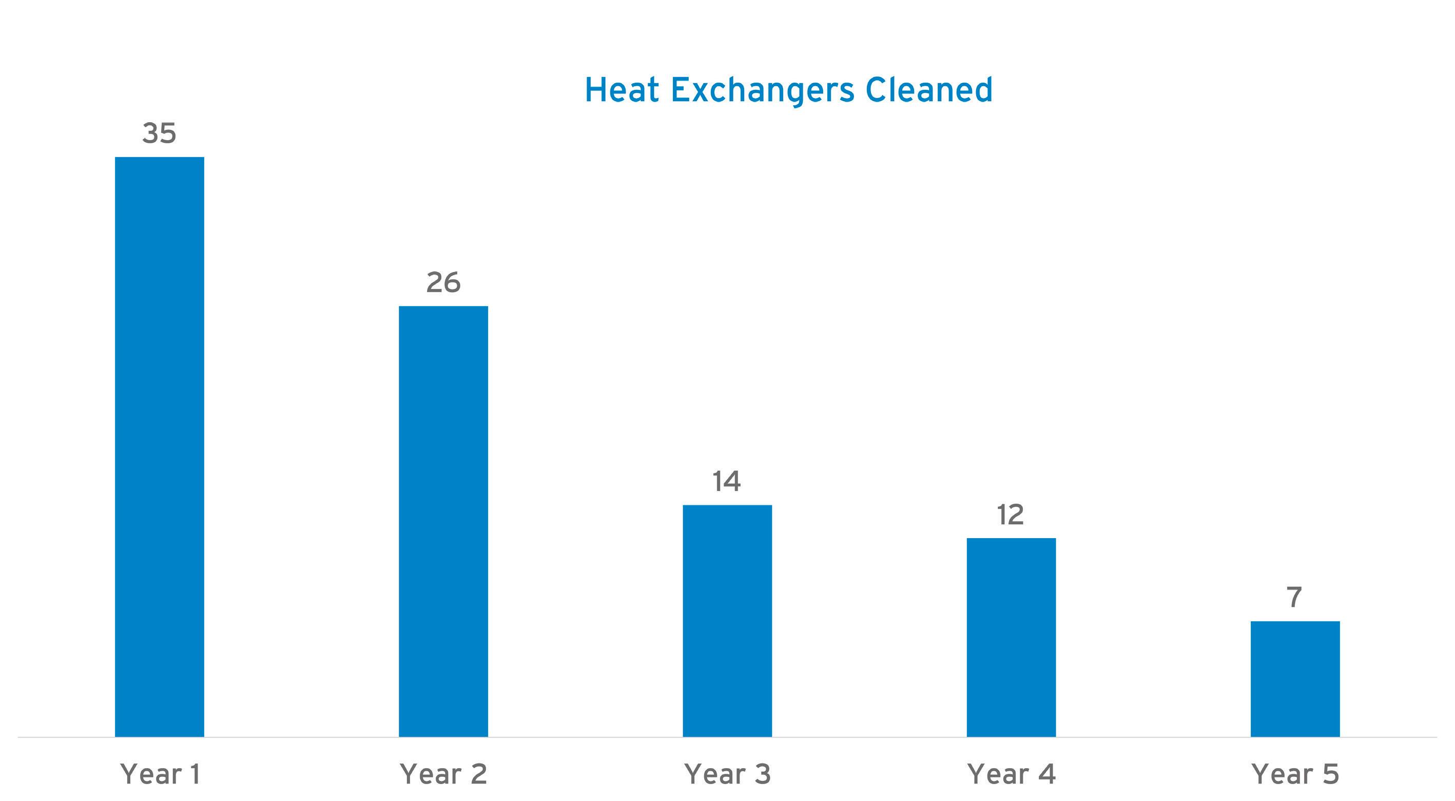
December 2022 HYDROCARBON ENGINEERING 46

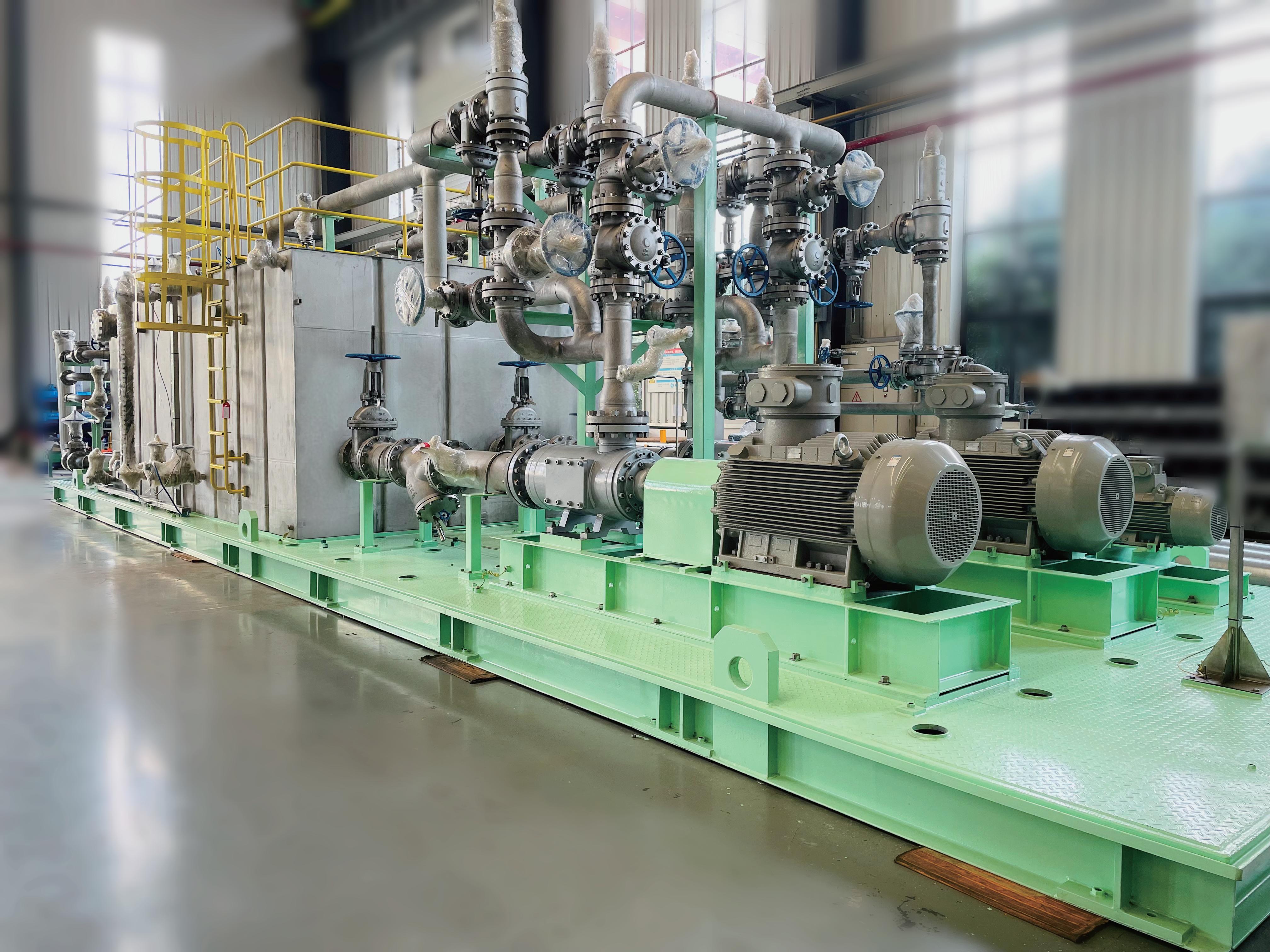
to heat exchanger failure could have cost the company millions of dollars in both lost production and environmental penalties. To address this potential risk, the company collaborated with the Nalco Water team to implement the OMNI Heat Exchanger Reliability program in its operations.
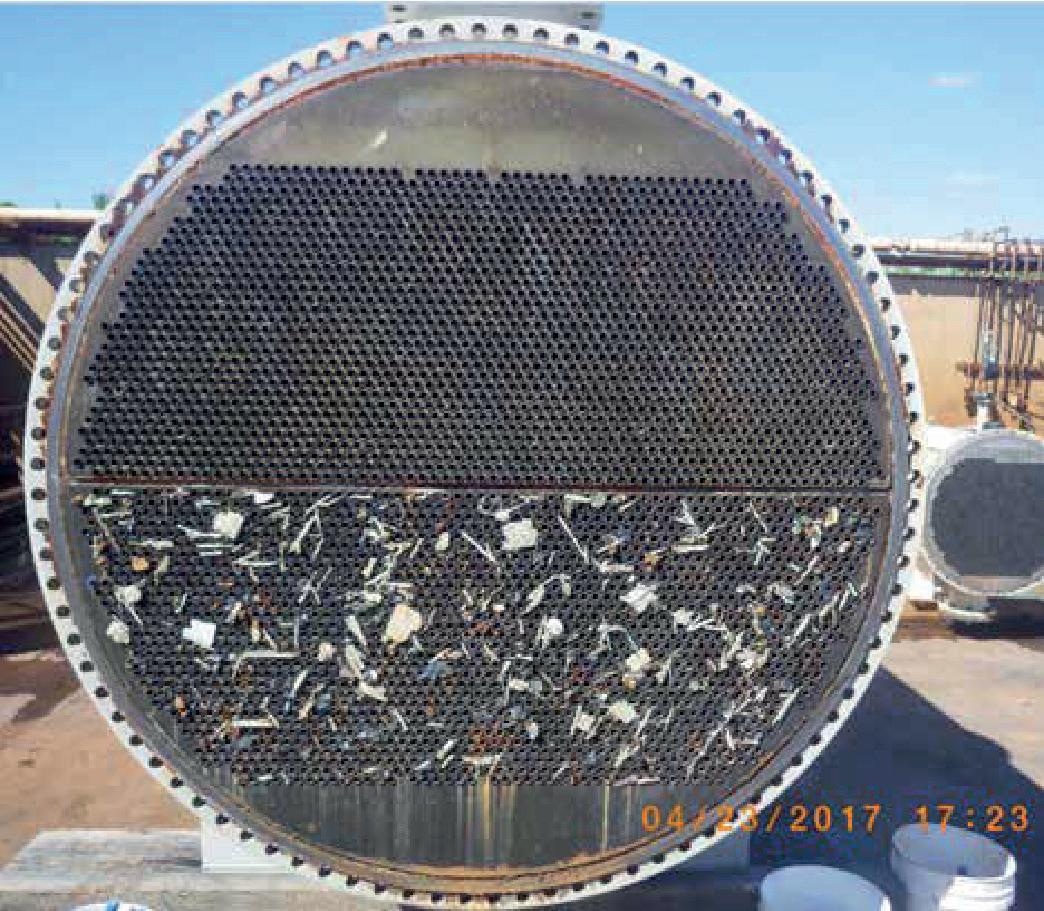
The first step was to collect and validate the data for all heat exchangers across the company’s facilities. The performance data was loaded into the program on the ECOLAB3D platform.

The solution detected a 90% decrease in the designed water velocity of a critical heat exchanger. After further investigation, the team discovered that the inlet tubesheet
of the heat exchanger was obstructed with cooling tower fill that was drawn into the system during routine cooling tower maintenance. The issue was corrected by removing the debris, which returned the heat exchanger to its design cooling water flow. The corrective action ensured asset performance and operation reliability. The plant saved over US$1 million in production losses and approximately US$50 000 in heat exchanger replacement costs. These savings were generated by correcting just one critical issue. With more than 1000 other heat exchangers, the plant stands to save additional costs and decrease downtime in the future.
Avoiding revenue loss due to microbiological fouling
In another example, when a nitrogen producer based in North America decided to expand its production cycle, this increased stress on the company’s assets, including heat exchangers. Because the facility used unfiltered river water as a make-up water source and consequently had a history of fouling, the company decided to implement OMNI Heat Exchanger Reliability in its process to closely monitor the conditions.
The Nalco Water team started with a comprehensive survey that compared current heat exchanger operations to historical and design data. The survey indicated that the monoethanol coolers were the most stressed heat exchangers in the system. To better understand the situation, the team installed OMNI Heat Exchanger Reliability sensors on the coolers to extract additional performance data and insights.
Figure 4. Debris in the inlet of the critical heat exchanger.
During the first three weeks after the sensors were installed, the performance data remained steady. In week four, however, plant operators observed a slight but consistent decrease in U-Value. After correlating chemistry indicators, the cause was determined to be microbiological fouling. Microbiological slime is one of the most insulating substances encountered in cooling water systems. A customised system of bio-cleaning was implemented, and the U-Value gradually returned to a value that was sufficient enough to enable maximum production through the next planned outage. As a result of OMNI Heat Exchanger Reliability, the company was able to proactively detect the anomalies and prevent production loss.
Conclusion
Figure 5. Cooling tower fill observed in the heat exchanger.
Digital tools such as OMNI Heat Exchanger Reliability provide a new perspective for chemical processors and energy companies pursuing enhanced productivity and reliability. With access to strategically-obtained heat exchanger data, producers have increased visibility on the location of problem areas, which allows for implementation of proactive corrective actions. Although heat exchanger performance is only one component of an entire production process, optimising it with the support of digital predictive tools brings substantial benefits to the entire process. As more companies choose to embrace this new trend, there is no doubt that digitalisation and predictive analytics from services such as OMNI Heat Exchanger Reliability help improve production processes and create new industry standards.
December 2022 HYDROCARBON ENGINEERING 48
Below-grade reinforced concrete sulfur storage pits provide containment and bulk conveyance of molten sulfur products in the elemental sulfur process stream. With the appropriate detailing1, these critical equipment assets can provide long-term service in incredibly harsh process environments, allowing for dependable process throughput. Unfortunately, either due to cold temperature environmental conditions, power interruptions, and/or process upsets, the realisation of a cold sulfur pit with hardened sulfur and carsul deposits (a byproduct delivered in the process stream) can be a source of major anxiety for sulfur process professionals and plant management.
The nature of elemental sulfur Historically, sulfur was also called brimstone, which means ‘burning stone’. In the past, it was mined from deposits associated with volcanic activity. Presently, most elemental sulfur is produced as a byproduct of removing sulfur-containing contaminants from natural gas and petroleum processing/refining streams by the largest producers in the world (Kazakhstan, Russia, Canada, Qatar and the US).2
Sulfur containment safety
Prior to working in and around any sulfur recovery unit (SRU) infrastructure, a safety execution plan (SEP) should be developed that identifies task hazards, as well as environmental and ergonomic concerns associated with the planned scope of work (SOW). Essentially, the SEP establishes a series of steps/practices that closely follow industry best practices and Occupational Safety and Health Administration (OSHA) safety protocols to ensure worker safety and environmental stewardship. The SEP is integral to the daily toolbox meetings, along with manager/supervisor safety audits, in order to
educate, inform and implement task hazard analysis checkpoints associated with the SOW.


When reviewing molten sulfur containment, several ‘red flags’ surface regarding safety, due to the fact that sulfur and sulfurous compounds are frequently corrosive to materials that they are in direct contact with. Specifically, containment materials that are typically unreactive to molten and/or sulfur cake forms are often readily attacked when sulfur co-mingles with moisture/water sources. The result of these materials co-mingling is the formation of acidic compounds that can be corrosive, especially when contact occurs at elevated temperatures. When hardened sulfur cake needs to be removed from sulfur containment structures, mechanised equipment (i.e. skid-steers, backhoes, excavators, etc) should be employed for the most part, and craft labour used in those areas that are inaccessible by mechanised equipment – wherever possible. The goal is to minimise the exposure of craft labour to known task hazards and reduce, when possible, the level of personal protective equipment (PPE), by employing engineering controls.

Sulfur differs from most combustible dust by having a relatively low autoignition temperature of 482°F (250˚C), and a flash point of 405°F (207˚C). The handling of solid sulfur in pits and tanks can create a dust cloud which can then produce a static charge among the air-suspended sulfur particles. The static discharge can readily cause ignition of the dust cloud and create explosive conditions, and sulfur dust explosions do occur in the refining and gas industry. Research has determined that dust concentrations of as low as 35 mg/l of sulfur dust in air are explosive.3
Owing to the pyrophoric nature of sulfur cake and metals affected by sulfurous contact, moisture must often be used to provide spark/fire suppression during hardened sulfur cake removal. The working
December 2022 49 HYDROCARBON ENGINEERING
Thomas Kline, Structural Technologies, USA, details the process of hardened sulfur and carsul removal from below-grade reinforced concrete sulfur storage pits.
surface should be kept wet so that dust is not allowed to accumulate. A slight spray of water should be applied to the working surface prior to excavating the sulfur. A continuous spray is not necessary, but the sulfur should always be wet. Diligence in protective PPE usage and adhering to appropriate safety protocols by craft labour is key to reducing the possibility of acidic compound contact and providing overall hazard mitigation. Safe practices typically include the following:3
n Clean/dirty room dressing trailers and/or rooms for PPE gearing-up/removal.
n Single or multiple-use chemical suits, gloves and boots. External clothing that has become impregnated with sulfur should be removed or replaced.
n Duct-taped sealed seams at protective PPE transitions.
n Barrier skin cream application to potentially exposed skin ‘patches’ adjacent to respirator face and neck areas.
n Full-face respirators, organic vapour/acid-gas and HEPA cartridge filters, or full-face supplied-air respirators.
n Individual personnel hydrogen sulfide (H2S) monitors attached within 12 in. (30 cm) of facial regions.
n Confined space retrieval/extraction body harnesses.
n Easy access or escape routes in the verified work area.
n Confined space air movement via high-capacity fans/air horns.
n Atmospheric testing that should include monitoring for sulfuric acid (Dräger Tubes) and sulfur dioxide (SO2) in addition to oxygen, LEL, etc.
n Use SO2 analysers to monitor the atmosphere around the pit or tank. Since sulfur burns with a dim blue flame, it may not be detectable if the area is well lit.
n Eye washing stations.
n Emergency shower locations.
n Compressed air should not be used to remove or clean dust from any surface since the agitation may create a dust cloud.
n Ground all areas that may develop a static charge.
n Avoid use of plastic tarps that are not anti-static. General purpose plastic can generate a static charge that could ignite a sulfur dust cloud.
n Hot surfaces can easily ignite dust clouds and/or dust accumulation on horizontal surfaces. The result of this can be a small fire that could ignite a dust cloud. Poorly ventilated electric motors, uninsulated steam lines, or electric lighting are examples of hot surfaces that can cause a fire.
It is also important to note that vacuum trucks should not be used in removing water and any hardened sulfur debris due to industry-reported fires and explosions associated with their use. Industry best practice is to diaphragm-pump (i.e. trash-pump) water out from within sulfur pits, and shovel remaining debris onto intrinsically-safe conveyors, or into waiting debris receptacles (i.e. tip-hopper dumpsters, wheelbarrows, or small buckets) rather than using vacuum removal techniques that can build and release static charges during operation.3
Typical approaches to ‘cold’ sulfur pits
The sulfur process stream is typically maintained in a molten state within sulfur pits via steam coils, steam-jacketed process lines, and heat-tracing. When molten sulfur temperatures fall below 250˚F (121˚C) for extended periods of time, molten sulfur solidifies and ‘cakes’. In its solid form, sulfur can no longer be pumped but instead requires mechanical means and methods to dislodge the product from process piping, equipment and vessels (see Figure 1). While the degradation process involving sulfurous compounds is well understood in operating sulfur pits both metallurgically4 and on cementitious products5, material corrosion will be initiated in the presence of moisture and oxygen in and around these civil/mechanical assets. When plant operations determine reductions in sulfur pit operating process temperatures, difficult decisions are often made to raise internal sulfur pit temperatures. These measures can include using temporary heating coils (see Figure 2), placing new molten sulfur over the top of cooler sulfur products, or bypassing current storage containments in lieu of auxiliary storage vessels (i.e. adjacent sulfur pits, above-grade sulfur tanks, railcars, or heated barges). Having process bypass options is always prudent. However, these attempts frequently fail to provide long-term relief from cold pits filled with caked sulfur and carsul.
Experience with cold sulfur pits
Figure 1. View of solidified sulfur in an extracted sulfur leg (left), and sulfur cake accumulated at the base of a sulfur pit that went ‘cold’ during a unit-wide power outage (right). Note the extensive damage to the sulfur pit walls due to sulfurous acidic attack exposing embedded steel bars (for reinforcement).
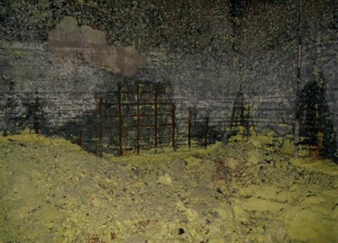
Cold sulfur pits filled with sulfur cake are frequently thought of as something that can be remelted, and the product pumped from the pit into waiting containment vessels. Unfortunately, the inherent crystalline form of hardened sulfur makes solid sulfur an excellent insulator and therefore difficult to remelt on a large-scale. This is also why it can be hazardous to walk on top of a perceived hardened level of sulfur cake. There may in fact be ‘hot spots’ (i.e. still molten sulfur) below the crust of the sulfur cake that
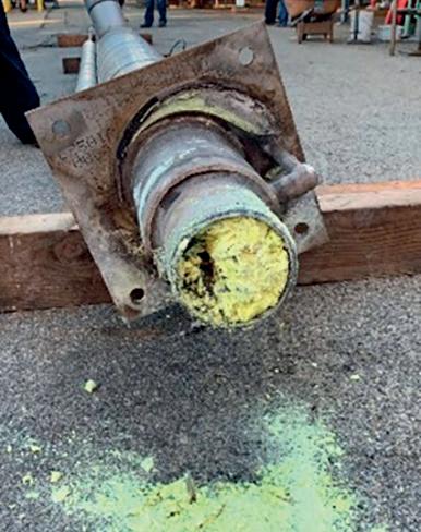
December 2022 HYDROCARBON ENGINEERING 50