Ampol –
Charging Ahead
Ampol: Takes charge with young engineering talent
AKZ: Seats for six
BMW: Follows Toyota in the Hydrogen sphere
Thales: Graduate program is open
VEHICLE TECHNOLOGY ENGINEER March 2024 Issue 39 Representing mobility engineers since 1927 www.saea.com.au


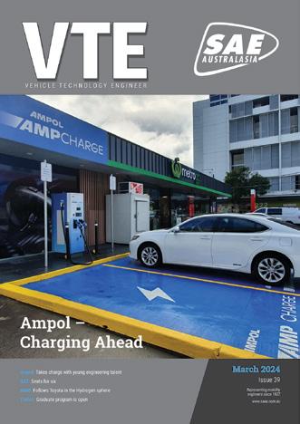
VTE | Contents VTE | 3 www.saea.com.au 20 SAE-A was founded in 1927 to address the need for further education for all facets surrounding Automotive Engineering, and now encompasses all mobility engineering industries in the Australasian region. The SAE-A is a non-profit organisation that works to serve the needs of its members and to promote the relevance of mobility related technologies to governments, industry and the community in general. About the SAE-A 18 Ampol takes charge When five seats are not enough Contents March 2024 Special Features 18 Ampol – Charging Ahead 20 AKZ Vehicle Engineering and Design Services – Take a seat 22 BMW – Hydrogen is the way forward 24 Australian Auto Aftermarket Expo – Showtime in Melbourne 26 Thales – Graduate program is open VTE News 8 General News 10 Automotive News 12 Truck & Bus News 14 Defence & Aero News 16 Overseas News Society News 4 Notes from the Chair - Gary White 5 SAE-A News Technical Feature 27 Technical – Crashworthiness Review for Electric Vertical Take-Off and Landing Vehicles and Implementation of the Automotive Safety Approach The editor, publisher, printer, the Society of Automotive Engineers – Australasia (SAE-A) and their employees, directors, servants, agents and associated or related entities (Publishing Entities) are not responsible for the accuracy or correctness of the text, pictures or other material comprising the contributions and advertisements contained in this publication or for the consequences of any use made of the products, services and other information referred to in this publication. The Publishing Entities expressly disclaim all liability of whatsoever nature for any consequences arising from the use or reliance on material contained in this publication whether caused to a reader of this publication or otherwise. The views expressed in this publication do not necessarily reflect the views of the Publishing Entities. The responsibility for the accuracy or correctness of information and other material is that of the individual contributors and the Publishing Entities do not accept responsibility for the accuracy or correctness of information or other material supplied by others. To the extent permissible by law, the Publishing Entities exclude all liability pursuant to the Competition and Consumer Act 2010 (Cth) or other applicable laws arising from statute or common law. Readers should make their own inquiries prior to the use of, or reliance on, any information or other material contained in this publication, and where necessary seek professional advice. All rights reserved. Reproduction in whole or part without the written permission of SAE-A is strictly prohibited. 10 Jayco Site visit Delegation to Canberra supporting Australian manufacturing Top 5 Robot Trends 2024 8 5 Ampol is rolling out its AmpCharge network with the help of engineering graduates About the cover
VTE Published By:
Society of Automotive Engineers - Australasia
ABN: 95 004 248 604
Address:
VACC House
650 Victoria Street, North Melbourne VIC 3051
Phone: 0403 267 166
Email: info@sae-a.com.au
Web: www.saea.com.au
Membership & Subscriptions
Rose De Amicis
Email: rose@sae-a.com.au
Events
Suzanne Nicol
Email: events@sae-a.com.au
Board of Directors:
Adrian Feeney – CEO
Gary White – President
Greg Shoemark – Vice President
Mohammad Fard – Technical Director
Noi Vera (Kotev) – Dir Events/Training
Paul Nation – Director Treasurer
Martha Oplopiadis – Director Membership
Bernie Rolfe – FISITA & SAE Liaison
James Soo – Autonomous/EV Vehicles
Richard Taube – Board Director
Michael Waghorne – Dir Truck & Bus
Magazine Production:
Editor
Mandy Parry-Jones
Trading Terms Media
Email: mandypj@optusnet.com.au
Mobile: 0409 806 986
Design
Brigid Fraser
Email: fraseram@optusnet.com.au
Mobile: 0413 009 122
Advertising
Jill Johnson
Jill Johnson Media
Email: jj@jilljohnsonmedia.com.au
Mobile: 0409 217 624
VTE Industry Partner:
Excellerate Australia
Follow SAE – Australasia:



Gary White
President
Society of Automotive Engineers – Australasia
Global automotive developments/Australian vehicle efficiency standards
Welcome to the March 2024 issue of VTE magazine. I hope you enjoy the mobility industry updates and contributions from our members. I have observed some significant developments very recently that signal a transition of focus by our global automotive manufacturers and our local supply chain.
In the recent years, most carmakers, notably VW and GM are on an EV software development capability drive. In the past months, GM has hired ex-Apple and ex-Google (two of the IT giants) executives to rebuild in-house software development competence. Presumably they will bring their key team members with them. In this scenario, carmakers may be successful in unshackling themselves from the Silicon Valley domination of automotive software, but we will have to wait and see.
At home, the introduction of vehicle efficiency standards is generating much debate, with opponents saying they will push vehicle prices up, force manufacturers to switch to hybrid powertrains, and limit consumer choice. A contrasting view is that the prevailing Australian preference for heavier “feature-laden” vehicles significantly offset gains due to fuel efficiency technologies, and this drives both product cost and fuel consumption growth. The introduction of fuel efficiency standards will certainly shake up the existing market offerings, which we know is inevitable.
The Australian love-affair with ICE-powered pickup trucks (LCVs) and SUVs is in my opinion approaching its peak. We are now seeing pricing for relatively low-tech (ICE powered) but feature
laden trucks well in excess of similarly spec’d EVs (from the passenger car perspective) and FBT concession limits, bluntly indicating that manufacturers are “making hay while the sun shines”. New product launches indicate that Chinese truck manufacturers are well positioned to capture this short-term market boom as their product quality and specifications challenge the Thailand-produced incumbents, and they are now bringing EV-LCV/SUV products to the Australian market. With continued development of battery capacity and charging infrastructure, our EVpowered weekends look secure.
Current sales figures show the majority of Australian new vehicle sales are SUVs and LCV/ trucks so, it is not surprising that we have a strong OE and aftermarket accessory design and manufacturing sector.
I believe design and engineering of commercial and off-road vehicle accessories for improved vehicle compatibility and to enhance safety ratings can become a significant opportunity for automotive engineers, and LCV/SUV accessory developers. Australia is arguably the best validation environment for these new products, providing the stepping stone to export markets.
So, essentially, the environment is changing, providing new opportunities for automotive designers, engineers and software developers globally and at home. I look forward to opening this next chapter in the Australian context, and I will contribute some of my research findings in coming issues.
Enjoy the read!
Introduction | Secretary, CEO and Chairman Society of Automotive Engineers 4 | March 2024
SAE-A’s think-tank
With so many possibilities it’s hard to choose the right ones, that’s what the SAE-A board is up against when determining the events and occasions that are offered to members.
Recently a sub-committee got together with Suzanne Nicol to scope out the options for 2024 which range from events with FISITA, technical conferences, training, webinars, site visits, excellence awards and forums plus, of course, Forumla SAE-A.
The list is long, and it will take time to pare down the events that are of most interest to members and if any members have a particular event they would like to see on the calendar please contact Suzanne Nicol at events@sae-a.com.au
This is the calendar so far this year...
Jayco site visit
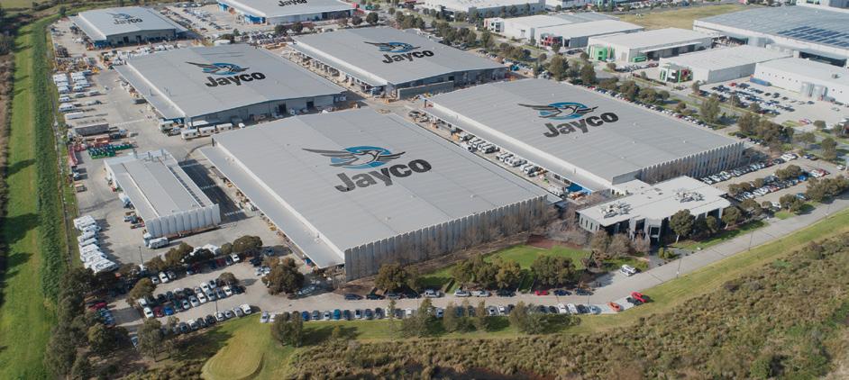
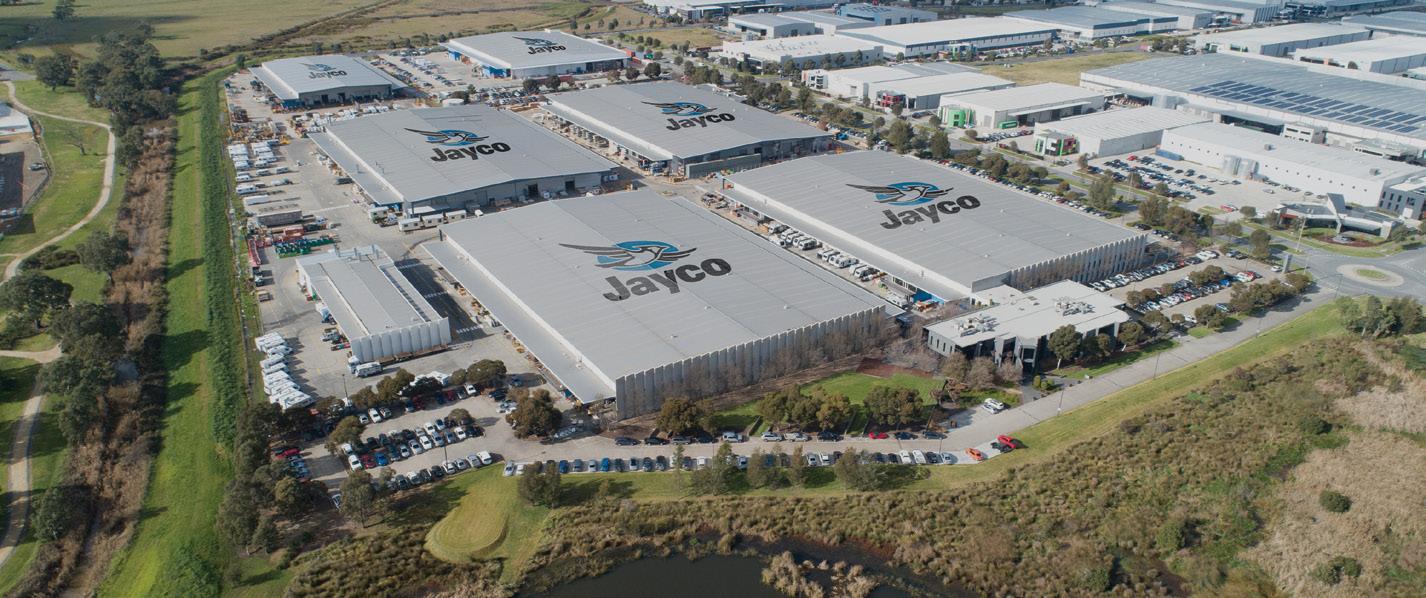
On Thursday 7 March, the SAE-A organised a site visit to Australian owned Jayco Corporation (Jayco) with 13 members taking advantage of the tour which focused on this growing industry in Australia.
Based in Dandenong on a 50-acre purpose-built facility, Jayco was established in 1975 and now employs more than 1100 people specialising in the design, manufacture and distribution of a wide range of caravans including recreational vehicles.
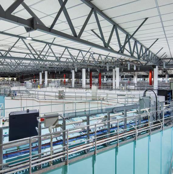
Australia’s Synchrotron
1 May 9.30am
800 Blackburn Rd, Clayton Vic 3168
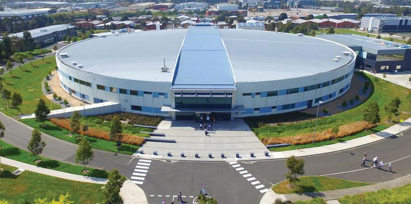
The Australian Synchrotron in Clayton is a world-class science facility that supports a broad range of outstanding research across medicine, nanotechnology, manufacturing and mineral exploration.
Among many of its benefits is that it can produce a powerful source of light a million times brighter than the sun. Explore this world-class facility that can examine materials at an atomic level.
Members $30, non-members $50, students $25.
You must register to attend: www.saea.com.au/events
SAE-A AGM & networking night
30 May – Auburn Hotel
85 Auburn Rd, Hawthorn East 3122
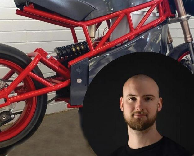
Enjoy a night of networking with SAE-A members and some of our Formula SAE-A teams. Following our AGM that starts at 6pm a canape menu will kick off at 6.30pm. Dennis Savic from Savic Motorcycles will be our guest speaker at 7pm, leaving plenty of time for some great networking opportunities. Denis is a former Formula SAE-A participant and long before electric vehicles were an established part of Australia’s transport landscape, he was building the foundations for the country’s first high-performance electric motorcycle.Members $70, Students $50
You must register to attend:
www.saea.com.au/events
Introduction to Crash Investigation and Reconstruction
Presented by Delta -V Experts, participants will learn how to examine, record and interpret the results of a collision and provide an opinion as to speed, direction of travel, vehicle and person movements and probable contributions of the human, vehicle and environment factors associated with the collision effectively and efficiently.
This is a five-day course starting on 22 July at 9am. The cost is $945 – $1415.
For more information please visit www.saea.com.au/events or contact Suzanne Nicol at events@sae-a.com.au
SAE | News VTE | 5
www.saea.com.au
Briefs
Member benefits with DELL

The SAE-A has established a new member benefit partner with Dell Technologies. Members must log in to their membership portal to access the unique code to receive the discount.
A list of all our other member benefits can be picked up from this link www.saea.com.au/benefits
No more PO
Due to the small amount of hardcopy mail received nowadays the SAE-A has decided to close its Post Office Box.
All hardcopy mail should now be sent to the street address which is VACC House, Level 3, 650 Victoria Street, North Melbourne Vic 3051.
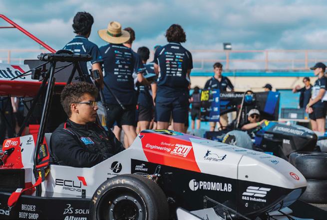
Formula SAE will continue to accept entries in the Internal Combustion (IC) class in 2024, as well as entries for EV and Autonomous vehicles –two classes that are growing in popularity. IC is not leaving us yet, already this year two teams have expressed their intention to register for the IC class, which considering the 2023 event concluded only few months ago is a very good start.
Team Registration for the 2024 Formula SAEAustralasia competition will open on 15 April 2024.
The 2024 event will be held from 5-8 December 2024 at Calder Park Raceway, in Calder Park, Victoria, Australia and will feature:
• Static and Dynamic events
• Careers Expo
• Awards Presentation
We look forward to providing more details on the 2024 event as they come to fruition.
Monash Motorsport wants more like Lochie
Lochie Gawley-Price joined Monash Motorsport in 2019 and worked as an aerodynamics engineer during his time on the team, primarily focussing on aerodynamics validation and CFD workflow development.
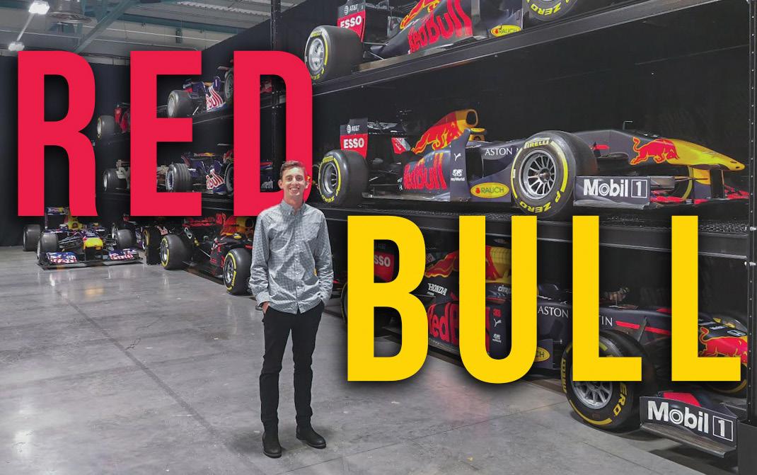
At the same time, he was able to develop a variety of other skills such as programming and data analysis. His last year as a fulltime member on the team was in 2021, but nevertheless, Lochie continues to help the team as an alumnus whenever he can.
Lochie has just completed his placement at Oracle Red Bull Racing and is now moving on to a permanent position there. His primary role in Red Bull was an intern and included the design and development of vehicle aerodynamics, as well as data analysis of track tests.
A secondary role he took on during his placement centred around developing software for Oracle Red Bull Racing’s on track live analysis.
New Members
While recognising that the knowledge gained from his time at Monash Motorsport greatly helped him in his work at Oracle Red Bull Racing, Lochie believes that Monash Motorsport is more than developing skills for the future. For him, the team played an important part in creating friendships and nurturing a great sense of camaraderie between teammates.
“The team is more than learning skills though, with friendships formed in the shared challenges that you will face,” Lochie GawleyPrice said.
Monash Motorsport is currently recruiting new members. To join our team, please fill in the recruitment form at: https://linktr.ee/ therealmonashmotorsport
The SAE-A would like to welcome the following new members and milestone members:
New Members
Frank Cottonaro
Luke Dan
Dean De Valence
Jack Quigley
Manojkumar Vanangamudi
Corporate Mars Institute
Student
Aakash Shaun Hurry
Kurtis Walsh
ZiLing Wang
Milestone Members
Ayres Desmond- 50 years
Kwok Kwong Lau - 40 years
Andrew Gwinnett - 40 years
Mark Egan - 40 years
Greg Shoemark - 30 years
William Hamel - 30 years
John O’Reilly - 30 years
Owen Johnstone - 30 years
Ali Akbarian - 20 years
Christopher Goddard - 20 years
Allan Reed - 20 years
Wai Ping Adrian Ling - 20 years
Blake Winter - 10 years
Cameron Brimelow - 10 years
David Cao - 10 years
Stephen Castles - 10 years
Rodney Ferguson - 10 years
Mario Filipovic - 10 years
Gihad Haidar - 10 years
Jack Hardy - 10 years
Ronald Heffernan - 10 years
Theo Iskander - 10 years
Steven Maggs - 10 years
Kathryn Saltmarsh - 10 years
Grant Wilson - 10 years
Naomi Arndt-Cooper - 10 years
Leong Chuan Simon Ho - 10 years
Andrew Crutch - 10 years
News | SAE 6 | March 2024
FSAE continues with IC

Metamaterial developed by RMIT
RMIT University researchers created a new metamaterial – a term used to describe an artificial material with unique properties not observed in nature from common titanium alloy.
But it’s the material’s unique lattice structure design, recently revealed in the Advanced Materials Journal, that makes it anything but common: tests show it is 50 percent stronger than the next strongest alloy of similar density used in aerospace applications.
“Ideally, the stress in all complex cellular materials should be evenly spread,” RMIT’s Distinguished Professor Ma Qian said.
“However, for most topologies, it is common for less than half of the material to mainly bear the compressive load, while the larger volume of material is structurally insignificant.”
Metal 3D printing provides unprecedented innovative solutions. By pushing 3D printing design to its limits, the RMIT team optimised a new type of lattice structure to distribute the stress more evenly, enhancing its strength or structural efficiency.
“We designed a hollow tubular lattice structure that has a thin band running inside it. These two elements together show strength and lightness never before seen together in nature,” said Qian.
“By effectively merging two complementary
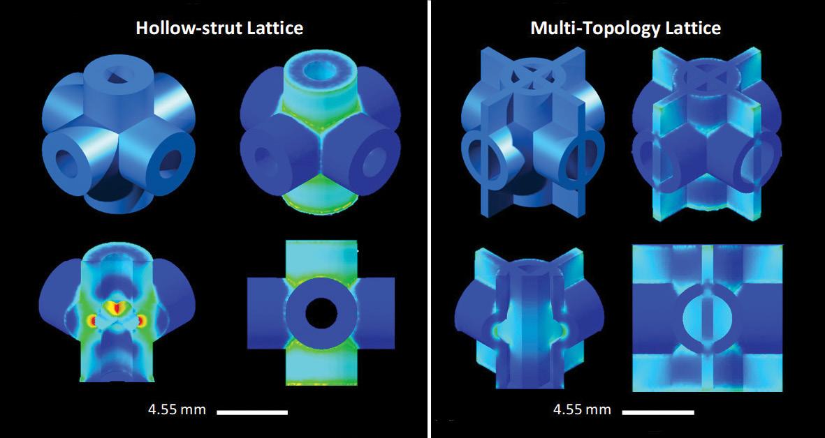
lattice structures to evenly distribute stress, we avoid the weak points where stress normally concentrates.”
The 3D printed design was completed at RMIT’s Advanced Manufacturing Precinct using a process called laser powder bed fusion, where layers of metal powder are melted into place using a high-powered laser beam.
Testing showed the printed design – a titanium lattice cube – was 50 percent stronger than cast magnesium alloy WE54, the strongest alloy of similar density used in aerospace applications. The new structure had effectively halved the amount of stress
Top 5 robot trends 2024
The stock of operational robots around the globe has hit a new record of about 3.9 million units. This demand is driven by a number of exciting technological innovations.
1 Artificial Intelligence (AI) and machine learning
Robot manufacturers are developing generative AI-driven interfaces which allow users to program robots more intuitively by using natural language instead of code. Workers will no longer need specialised programming skills to select and adjust the robot’s actions.
2 Cobots expanding to new applications
Rapid advances in sensors, vision technologies and smart grippers allow
robots to respond in real-time to changes in their environment and thus work safely alongside human workers.
3 Mobile Manipulators
Mobile manipulators, so called “MoMas” are automating material handling tasks in industries such as automotive, logistics or aerospace. They combine the mobility of robotic platforms with the dexterity of manipulator arms. This enables them to navigate complex environments and manipulate objects, which is crucial for applications in manufacturing.

concentrated on the lattice’s infamous weak points. The double lattice design also means any cracks are deflected along the structure, further enhancing the toughness. The team plans to further refine the material for maximum efficiency and explore applications in higher-temperature environments.
Titanium Multi-Topology Metamaterials with Exceptional Strength (https://onlinelibrary.wiley.com/doi/ full/10.1002/adma.202308715)’ was published in Advanced Materials (DOI: 10.1002/adma.202308715).
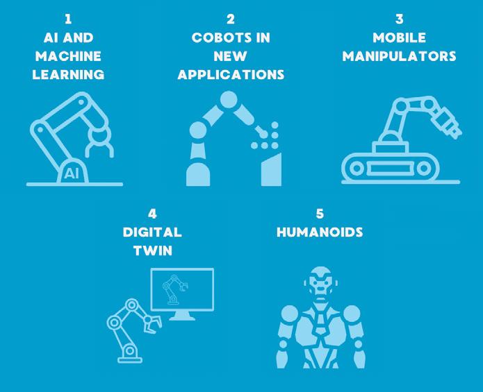
4 Digital Twins
Digital twin technology is increasingly used as a tool to optimise the performance of a physical system by creating a virtual replica. Because the twin exists purely as a computer model, it can be stress-tested and modified with no safety implications while saving costs.
5 Humanoid Robots
Robotics is witnessing significant advancements in humanoids, designed to perform a wide range of tasks in various environments. The human-like design with two arms and two legs allows the robot to be used flexibly in work environments that were actually created for humans.
More information at: https://ifr.org/ifr-pressreleases/news/top-5-robot-trends-2024
News | General
8 | March 2024
Final report on the Pathway to Diversity in STEM
Australia has an urgent need to boost its STEM workforce to take advantage of opportunities in sectors like renewable energy, critical minerals and quantum.
The Minister for Industry and Science Ed Husic released the final report of The Pathway to Diversity in STEM Review
The independent Diversity in STEM Review Panel has made 11 detailed recommendations, based on 12 months of public consultation, conversations and research.
The Review Panel’s recommendations aim to create structural and cultural change within Australia’s STEM system to support greater diversity and inclusion.
The independent Review Panel’s recommendations include:
• establishing a dedicated advisory council to guide government and mobilise change.
• changing grant and procurement processes for STEM-related programs.
• enhancing the current Women in STEM program suite and establishing programs for other cohorts underrepresented in STEM education and jobs.
The panel heard from around 385 individuals and 94 organisations through conversations, interviews and workshops, and received 300 written submissions.
The Review Panel’s recommendations were also informed by key research reports including the STEM Career Pathways report for the National Science and Technology Council, which was released recently and prepared by Science and Technology Australia.The STEM Career Pathway report identifies barriers to STEM careers and ways to build the workforce. These include:
• Opportunities for better coordination between university and vocational sectors, improved access to work-based placements, and micro-credential training to upskill existing workers.
• Better engagement of skilled migrants and international graduates on poststudy work visas by increasing employer understanding of overseas qualifications and graduates’ post-study work rights.
The Pathway to Diversity in STEM Review Panel’s final recommendations can be found at: www.industry.gov.au/diversityinstemreport
The STEM Career Pathway report can be found at: www.chiefscientist.gov.au/STEMCareerPathways
Uni Sydney to develop robotic satellite maintenance in space
SmartSat is backing the University of Sydney with $2.3 million to research and develop robotic maintenance of satellites while in orbit in a step to extend the lifespan of vital space infrastructure.
The new project will develop robotic satellite technologies to reliably connect with other satellites to perform in-orbit repairs and maintenance.
It will be led by the University of Sydney and is supported by SmartSat CRC and NSW-based industry partners Abyss Solutions, ANT61, Space Machines Company, Sperospace and Spiral Blue.
Servicing satellites in orbit is challenging due to harsh space conditions, potential risk of damaging expensive assets through collision during docking, and difficulties maintaining stability during maintenance.
Leading the project is Dr Xiaofeng Wu, Senior Lecturer in Space Engineering in the School of Aerospace, Mechanical and Mechatronic Engineering at the University of Sydney. He said developing foundational Australian

ISAM capabilities will help meet Australia’s future sovereign needs and equip local companies with advanced technologies, providing them with advantages in the global ISAM and broader space industry. This project brings together four technology areas into one research project, ensuring an end-to-end approach to address complex challenges facing in-orbit repair and satellite maintenance.
Briefs
AI scholarships on offer
Artificial intelligence (AI) ‘scholarships’ are on offer to one million Australians in a bid to increase the nation’s literacy of a technology estimated to be worth $4 trillion to the economy by the early 2030s. The free ‘Introduction to Artificial Intelligence’ microskill course is provided by the National AI Centre (NAIC), coordinated by Australia’s national science agency – CSIRO, and the Institute of Applied Technology Digital (IATD). The course will provide a non-technical introduction to AI fundamentals and is designed for people at the beginning their AI literacy journey.
For more information visit: https:// store.training.tafensw.edu.au/product/ introduction-to-artificial-intelligence/?_ ga=2.111309956.1073147357.16837698731545388492.1657075883&utm_source=NAIC&utm_ medium=MR&utm_campaign=AIMicroskills Water batteries
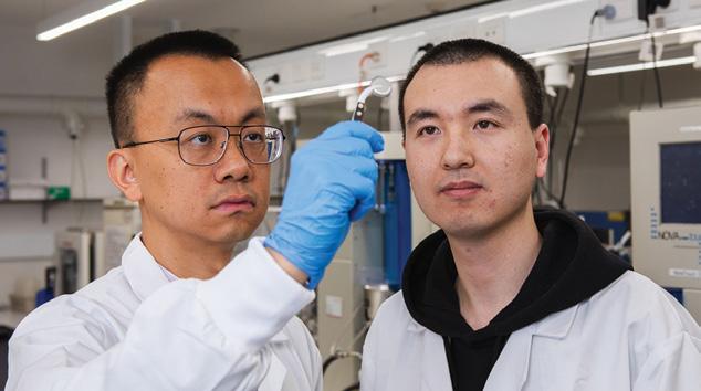
A global team of researchers and industry collaborators led by RMIT University has invented recyclable ‘water batteries’ that won’t catch fire or explode. Lithium-ion energy storage dominates the market due to its technological maturity, but its suitability for large-scale grid energy storage is limited by safety concerns with the volatile materials inside.
The team uses water to replace organic electrolytes, which enable the flow of electric current between the positive and negative terminals meaning their batteries can’t start a fire or blow up unlike their lithium-ion counterparts. The team coated affected battery parts with a metal called bismuth and its oxide (otherwise known as rust) as a protective layer that prevented dendrite formation.
Their work was published in the Advanced Materials Journal
Feds to crack down on dodgy training providers in automotive
The Australian Automotive Aftermarket Association (AAAA) has welcomed a new Federal government initiative to crack down on unscrupulous and non-genuine training providers. The AAAA strongly supports the legislation which will be an important step to remove dishonest and fraudulent RTOs that exist as a minority within the automotive training industry. The new legislation, the National Vocational Education and Training Regulator Amendment (Strengthening Quality and Integrity in Vocational Education and Training No. 1) Bill 2024 was introduced into Parliament by Hon Brendan O’Connor MP on Monday 12 February.
VTE | 9 www.saea.com.au
General | News
Delegation to Canberra supporting Australian manufacturing
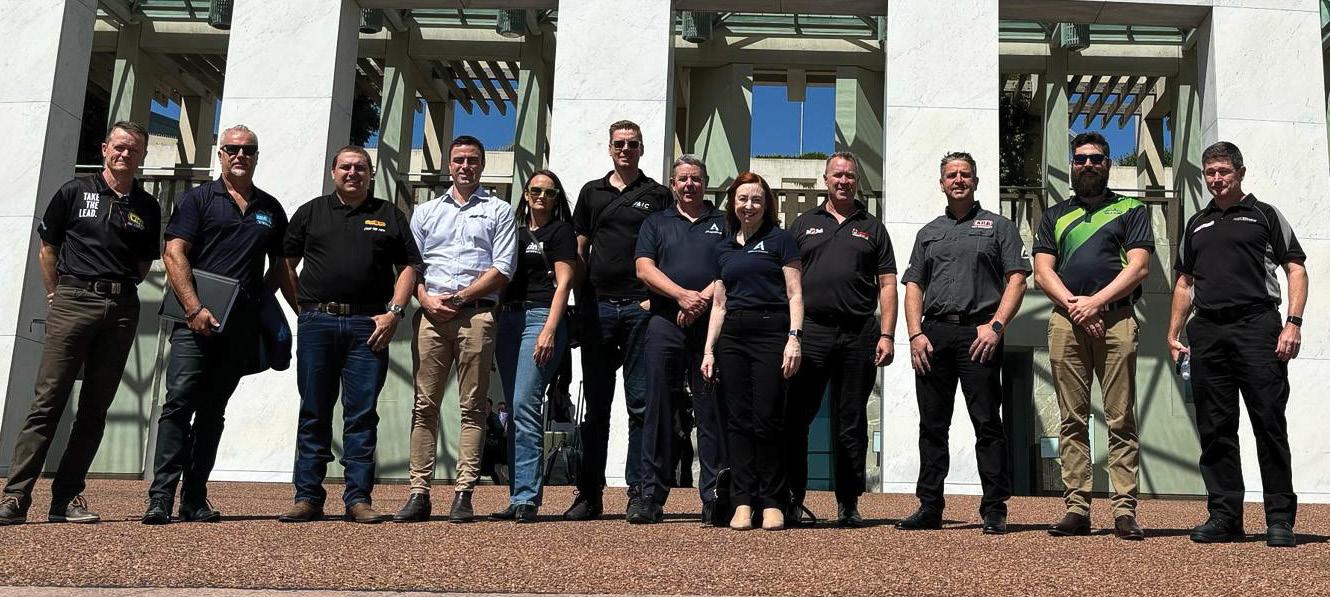
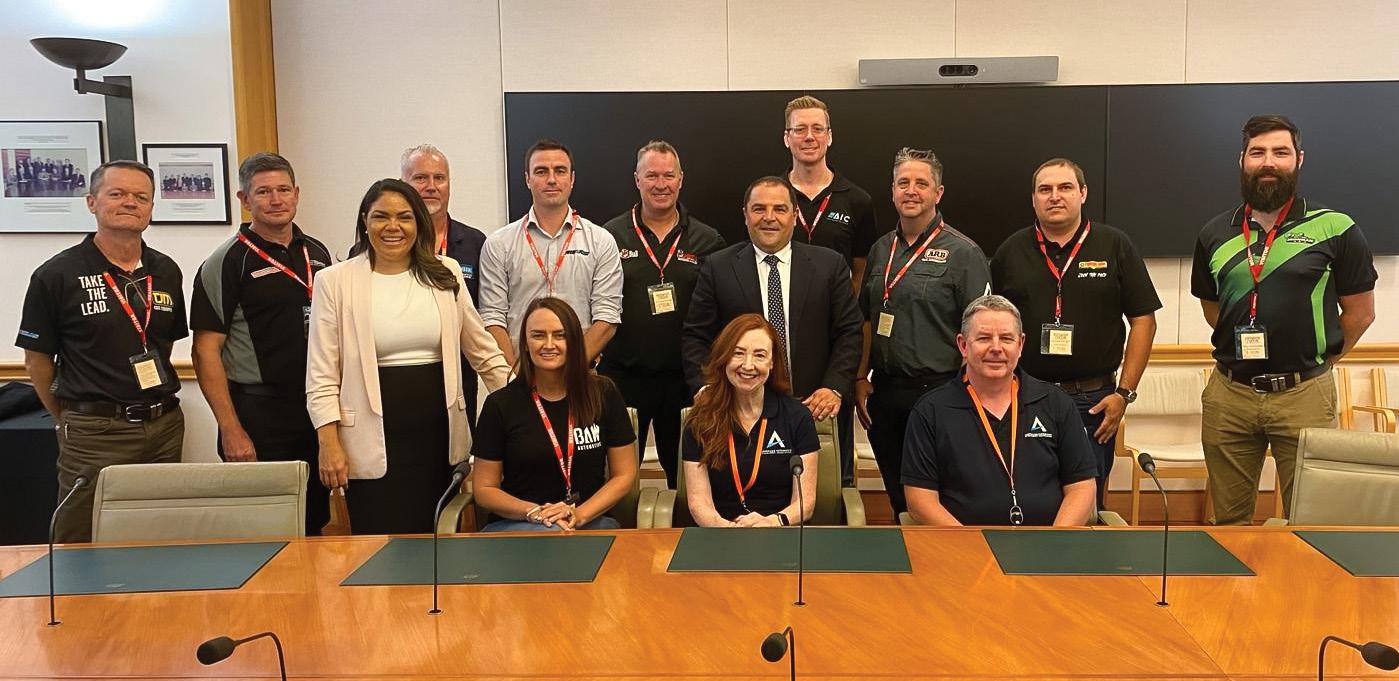
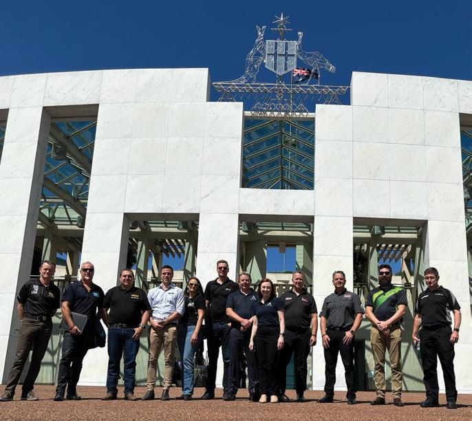
The Australian Automotive Aftermarket Association (AAAA) led a delegation to Canberra to undertake urgent discussions to support Australia’s automotive manufacturing industry.
A delegation of 10 Second Stage Manufacturers travelled to Canberra in February to seek constructive dialogue with the Department of Transport and key members of Parliament to highlight the importance of the automotive manufacturing industry and how the current federal government approval process is affecting the industry’s key fleet customers including mining, farming, and emergency services. The current process of requesting approval for essential and routine commercial modifications prior to first registration is an extremely difficult, time consuming process for businesses which is strangling the ability of Australian automotive manufacturers to innovate and compete in a fair manner.
“This process is killing what Australian engineering, design and manufacturing we have left, said Stuart Charity, CEO of the AAAA. “Companies in our industry have already withdrawn from the market due to frustrations with the approval system.
“Unless the system is fixed, we risk killing off our domestic manufacturers, making it impossible for Australia to evolve and meet the demands of global automotive trends and the future low emission global automotive industry.”
The AAAA actively flagged concerns to government about the potential negative ramifications of the Road Vehicle Standards (RVS) Legislation before its introduction in 2021.
F1 Pirelli tyres FSC compliant in 2024
Pirelli is the first company to produce a complete range of FSC (Forest Stewardship Council) certified tyres for motorsport.
Starting from this year, all the tyres used in the FIA Formula One World Championship will be marked with the FSC logo. This certifies that all the natural rubber within the tyre complies with stringent environmental and social criteria required by the FSC, the worldleading non-governmental organisation for sustainable forestry.
This certification, was announced on 10 October last year when Pirelli renewed its agreement as the global tyre partner of Formula One until at least 2027. It will apply to all the tyres used on track, throughout the season that includes pre-season testing.
“We were guaranteed assurances that second-stage manufacturers would not be left out and a clear pathway for second stage manufacturers would be developed, but this did not happen.
“Now it appears that a culture has developed within the Department of searching for reasons to block SSM (Second Stage Manufacture) applications. Combined with lengthy delays in reviewing applications, an ineffective IT system for mass commercial use and a very limited appeals process we are experiencing near catastrophic impacts for the Australian automotive manufacturing industry, and flow on impacts for our customers,” said Mr Charity.
Australia is a world leader in many important vehicle accessories. Australian companies are designing and developing these products locally and are exporting them to the world. This expertise enables the aftermarket to modify thousands of vehicles with upgraded systems to produce a final vehicle that is
safe and fit for purpose and used by mining, agricultural and emergency service sectors. AAAA’s Director of Government Relations & Advocacy Ms Lesley Yates said, “there are a number of bureaucratic issues that are leaving Australian manufacturers playing a game of chance with every approval. The current system lacks transparency, consistency, and accountability, all three aspects are needed for an approval process that is fit for purpose.”

The FSC-certified tyres have been introduced following an intense development program that began in 2022, which showed clear results in terms of both reliability and performance.
The first free practice sessions at the Bahrain Grand Prix saw the debut of these certified tyres at a Grand Prix event.
Together with the FIA and Formula One, the Italian firm has underlined its position in the front line of research and development into new technology, both on the technical and sporting side, to support the work that has already been done in reducing CO2 emissions throughout the entire life cycle of a Formula One tyre.
News | Auto 10 | March 2024
Women in Automotive enters a new era
Women in Automotive, an organisation promoting and supporting female and non-binary participation in the automotive industry, is embarking on an exciting new era of growth under new leadership and immediate national expansion.

The now independently run Women in Automotive will completely overhaul its corporate identity and membership offering as it supercharges its campaign to combat inequalities and a lack of opportunity for women and non-binary individuals in one of Australia’s largest industries.
“Women continue to be underpaid and underrepresented in the Australian Automotive Industry, from apprenticeships to boardrooms,” said Women in Automotive spokesperson, and one of its new directors, Rachel Reed-Butler.
“When women do find a place, studies by the Workplace Gender Equality Agency have shown that the gender gap on total remuneration is still around 19 percent.
“The Australian automotive Industry has taken great strides in transitioning from its maledominated roots into a more inclusive and
supportive career choice for all Australians, but we’ve really only seen the first steps.”
Ms Reed-Butler is part of a three-strong leadership team that have taken up the reins of Women in Automotive from the Victorian Automotive Chamber of Commerce (VACC) on 1 March 2024.
The leadership team includes nationally recognised motoring journalist Nadine Armstrong and highly-experienced TV and motorsport presenter Kate Peck.
This year celebrates the 25th anniversary of Women in Automotive, which was established by the VACC in 1999. Women in Automotive reaches 10,500 people through its various platforms and touchpoints, and has plans to grow this number considerably, starting with a national expansion of its membership base and events calendar.
NVES for Australia is controversial
According to the Federal Government the New Vehicle Efficiency Standard (or fuel efficiency standard), incentivises car companies to supply new cars that use less fuel per kilometre.
Under a New Vehicle Efficiency Standard, each vehicle manufacturer has a set average CO2 target for the vehicles they produce, which they must meet or beat. Over time, the CO2 target is lowered and in order to continue to meet or beat the target, companies must provide more choices of fuel-efficient, low or zero emissions vehicles.
The target is applied nationally on average. Suppliers can still sell any vehicle type they choose but they’ll need to sell more fuelefficient models to offset any less efficient models they sell.
If suppliers meet or beat their target, they’ll receive credits. If they sell more polluting cars than their target, they can either trade credits
with a different supplier, make it up over the next two years, or pay a penalty. For example, if a supplier generates debits in 2025, it will be able work in 2026 to generate credits to offset those debits.
Almost every advanced economy has implemented a New Vehicle Efficiency Standard except for Russia and Australia. Under the Government’s plan, an Australian New Vehicle Efficiency Standard is expected to come into effect from 1 January 2025, and will have Australia ‘catch-up’ to comparable markets, including the United States, by around 2028. There are continuing discussions among Australia’s car companies some in favour and some not in favour of the proposed standards.
Briefs
New COO for Premcar

Premcar announced the appointment of experienced automotive industry executive Craig Clarke as its Chief Operating Officer (COO). Mr Clarke has been assigned to lead and manage Premcar’s total engineering and manufacturing operations across the company’s two vehicle development and assembly sites in Epping, just outside Melbourne.
Mr Clarke is the first COO to be appointed by Premcar and this new leadership and management position results from the company’s continued growth.
Ford SuperVan faster than a SuperCar
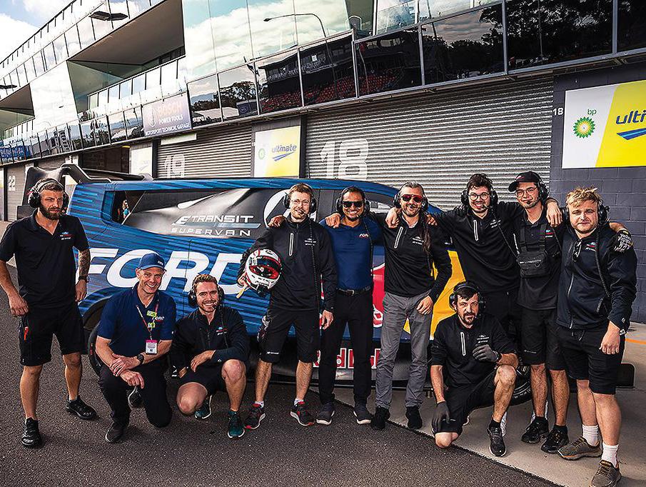
History has been made at Mount Panorama during the Thrifty Bathurst 500 event with the Ford Performance SuperVan 4.2 setting a trio of lap records, securing the benchmark time for the quickest closed-wheel vehicle, electric vehicle, and commercial vehicle to lap the circuit. With Romain Dumas at the helm, SuperVan 4.2 lapped Mount Panorama in an electrifying time of 1:56.3247, with a top speed in excess of 300km/h achieved on both Mountain Straight and Conrod Straight.
The lap time was set just after the Australian Supercars Top 10 Shootout, which finished with a pole time of 2:06.5465.
The new benchmark time from SuperVan 4.2 is a line in the sand, heralding a new era for electric vehicles, with the purpose-built demonstrator pushing the limits of EV performance during its time in Bathurst, beating an unrestricted GT3 car in the process.
This is now the second time Romain Dumas has re-written the history books with SuperVan 4.2, following his record-smashing run at the Pikes Peak International Hillclimb last year.
VTE | 11 www.saea.com.au Auto | News
Nadine Armstrong, Kate Peck and Rachel Reed-Butler.
Briefs
Cummins and Isuzu to build medium duty electric truck
Cummins and Isuzu Motors Limited recently announced an agreement to build a prototype medium-duty battery electric demonstration truck for the North American market. This will be the first zero-emissions truck to be produced by the Isuzu Cummins Powertrain Partnership (ICPP) which was formed in May of 2019.
Should the demonstration prove successful, Isuzu will then explore opportunities to commercialise medium-duty, battery-electric trucks with fully electric Cummins drive systems in North America.
The truck will be based on an Isuzu F-Series chassis and feature a Cummins PowerDrive6000 powertrain.
SafeAI reveals robo-electric truck
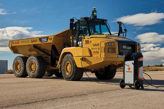
Working with Japanese construction company Obayashi Corporation, California based autonomous heavy equipment retrofitter SafeAI unveiled a Caterpillar 725 haul truck that is driverless and runs on battery-electric power.
The autonomous technology was provided by SafeAI, while the electric powertrain was fitted by AVIA Engineering, which specialises in integrating electricity into trucks.
In terms of sustainability, SafeAI claims that adding a driverless, emission-free car to a building site may enhance environmental performance by up to 13 percent, and that switching from diesel to electricity can reduce net life cycle emissions by more than 60 percent.
GoZero with school buses
The Commonwealth Bank (CBA) has closed $80 million in asset finance facilities with GoZero Group.
The financing is being utilised in part to source and ultimately replace existing diesel school charter coach services with electric buses for independent schools in Sydney, including Queenwood, Knox Grammar and Scots College, through GoZero’s charter business the NSBC Group.
Founded in 2020, GoZero is a leading manufacturer and integrator of Zero Emission solutions and vehicles for business and government fleets.
The funding is a key component of GoZero’s GreenSchools1000 initiative which aims to roll out 1000 electric coaches to service schools across Australia.
Trackless tram on trial
Australia’s first Trackless Tram is on the move, in a trial that the City of Stirling in Western Australia hopes will see this mid-tier transit become a future public transport service connecting Glendalough Train Station to the iconic Scarborough Beach precinct.
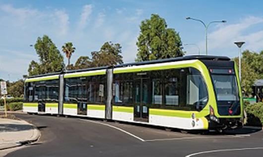
The 30-metre-long vehicle is currently undergoing a range of tests by experts from across Australia. This research will be used to understand how the vehicle operates, the impacts on the road surface and what the ride quality for passengers is like.
The trial which has been funded by the Commonwealth Government will continue until the end of November, giving government and local business stakeholders an opportunity to examine how the technology may be implemented in the Australian context and what benefits it could provide.
Mayor Mark Irwin said that the benefits offered by the Trackless Tram could be a game changer for urban regeneration in the city and set a new transport benchmark Australia wide.
“A permanent tram route in the City of Stirling would enable us to achieve a range of positive economic, business, transport and sustainability outcomes – reducing congestion and improving access to employment and tourist destinations,” he said. The project is being delivered with partners Curtin University, CRRC, Shanghai Electric and Infrastructure Technology Solutions.
Ambitious CO2 reduction targets
Legislators have reached a deal setting the most ambitious CO2 reduction targets for trucks and buses globally.
Truck and bus manufacturers fully support an ambitious decarbonisation agenda. However, the agreed implementation timeline remains extremely challenging in the absence of vital enabling conditions, stated the European Automobile Manufacturers’ Association (ACEA).
Taking note of the trilogue agreement, European truck and bus manufacturers emphasise that the highly ambitious CO2 reduction targets agreed upon must be backed up by credible enabling conditions.
“Electric charging and hydrogen refilling infrastructure, comprehensive carbon pricing schemes, and meaningful support measures for transport operators to invest quickly: these are the key ingredients for rapidly decarbonising the heavy-duty transport sector, in addition to zero-emission vehicles,”
emphasised Sigrid de Vries, ACEA Director General.
“We cannot continue boldly setting ambitious targets for vehicle manufacturers and expect swift and smooth implementation to follow. Without an enabling framework to shore up demand for the zero-emission models, achieving targets will be impossible, especially with the envisaged timeline,” de Vries explained.
To achieve targets by 2030, more than 400,000 battery-electric and hydrogenpowered vehicles will have to be on the road, and at least one-third of all new registrations must be zero-emission models. Europe needs at least 50,000 suitable charging stations (the majority being Megawatt Charging Systems) and at least 700 hydrogen refilling stations to make the equation work.
News | Truck & Bus
12 | March 2024
Iveco uses BASF to recycle truck batteries
Iveco and BASF, a leading chemical company and chemical supplier for the automotive industry, are partnering to provide a recycling solution for the lithiumion batteries of the Iveco’s electric vehicles.
This decision is part of Iveco Group’s circular economy strategy which follows the 4R Framework – Repair, Refurbish, Repurpose and Recycling – to increase the lifetime of the batteries while decreasing their overall environmental impact, and Iveco Group will ensure compliance with the Extended Producer Responsibility policy which holds producers responsible for the entire life cycle of the products they introduce on the market, from their design until end-of-life.
BASF, which has recently inaugurated Europe’s first co-located centre of battery material production and battery recycling in Schwarzheide, Germany, will organise and
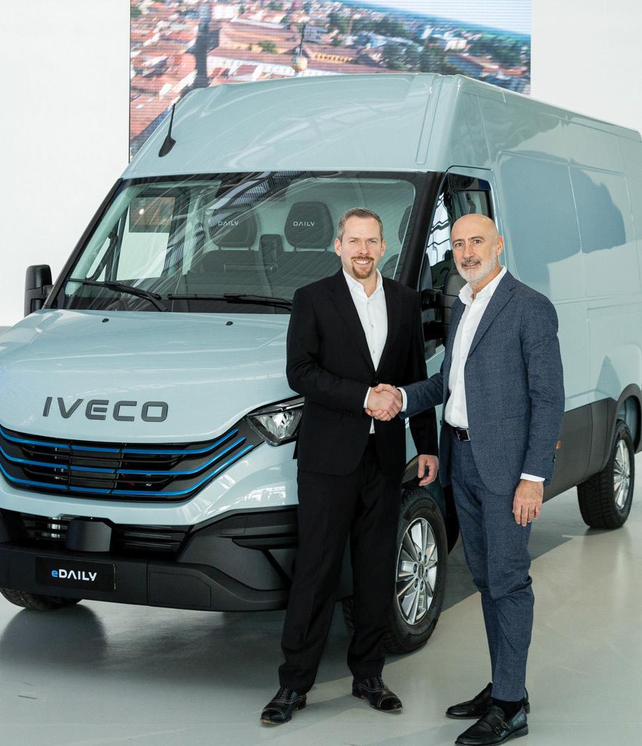
manage the entire recycling process for the lithium-ion batteries used on Iveco electric vans, buses and trucks. The agreement includes the collection, packaging, transport, and recycling of batteries, in various European countries.
Zero emissions buses to replace diesel in Queensland
Queensland Premier Steven Miles launched a new plan to deliver hundreds of zero emission buses through direct Government procurement.
The new zero-emission buses will replace aging diesel buses in operation on the Translink network.
It’s expected more than 400 buses will be locally manufactured, with the final number to be decided through a competitive procurement process.
The commitment builds on the Government’s recent decision to support construction of 200 new buses in Queensland, which will be Euro 6 diesel buses – the cleanest buses available to be made in Queensland in mass production at this point in time.
Translink already has 75 zero emission buses being trialled at eight depots across Queensland to help inform the design of zeroemission buses and depots from 2025. Local bus manufacturing will be boosted through local content requirements, which will see the creation of direct and indirect jobs and local opportunities for small and medium business to be part of the broader supply chain. Bus depots will also go clean, with new zero emission depots to be built and existing depots to be transitioned.
On road wireless charging
Trucks and buses could charge wirelessly as they drive on the highway, thanks to a new $3 million grant from the Australian Government to accelerate the nation’s electric vehicle sector.
In a world first, the Swinburne University of Technology-led project aims to implement an embedded dynamic wireless charging technology into roads, unlocking the uptake of electric heavy vehicles.
Electrifying heavy vehicles could save Australia $324 billion by 2050 but ensuring they have enough charge with heavy loads or over long distances is an urgent roadblock. This $8.2 million prototype for embedding advanced wireless charging infrastructure on regional roads was funded by the Australian
Government’s Cooperative Research Centres Projects (CRC-P) Grants scheme, supporting short-term collaborative research projects.
The project is a collaboration between ACE Infrastructure, SEA Electric, Fleet Plant Hire, Royal Melbourne Institute of Technology, Siemens, ARRB Group, and Net Zero Stack. The project is the outcome of several years of study conducted by world-leading researchers and PhD students at Swinburne’s New Energy Technologies Research Group.
Briefs
Scania mates biogas engines with diesel powertrains
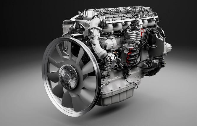
Scania first hinted at its new biogas engines last year, when its state-of-the-art engines arrived they came with a twist – they are now paired with parts of the company’s Super-based powertrain. The new biogas engines plus the G25 gearboxes and axles from the diesel sibling work so well together that fuel savings of five percent in long-haul have been confirmed.
“When we paired these components, it soon became obvious that we had a hit inthe making,” says Ola Henriksson, Senior Product Manager for Renewable Fuels at Scania Trucks.
Networks of biogas filling stations are expanding rapidly across Europe, driven by increased demand and by major players in the fuel industry. Reducing the CO2 footprint is no longer something only ‘green’ companies are doing for winning public acclaim: it is a pure necessity for most kinds of serious transporters. The new biogas engines are based on Scania’s 13-litre gas engine.
Aussie steel for Aussie train
The Queensland Train Manufacturing Program’s (QTMP) facility near Maryborough will be built with steel supplied by a Beenleigh company through a $40 million contract that will create new jobs and apprenticeship opportunities.
Beenleigh Steel Fabrications has been awarded the government contract to supply and install 2400 tonnes of structural steel for the buildings that will make up the QTMP train manufacturing facility at Torbanlea, near Maryborough.
Buildings being constructed by Beenleigh Steel Fabrications at Torbanlea include the train manufacturing facility, administrative building, a gatehouse and pump house.
Construction of the train manufacturing facility buildings is scheduled to start mid-2024 and is planned for completion in early 2025.
NewVolt to supply more voltage
Australian company NewVolt has released plans to build an electric truck charging network on the east coast of Australia and intends to have it operational by 2027, starting with its first truck charging station in Melbourne in 2025.
Another 14 other sites will be fitted out in Melbourne, Sydney, Brisbane,and on the Hume Highway with a further 40 sites by 2030. The sites will be powered through the use of renewable energy.
VTE | 13 www.saea.com.au Truck & Bus | News
Dr. Daniel Schönfelder, President of BASF’s Catalysts division and Francesco Donato, Head of Iveco Group Procurement.
Briefs
VTOL aircraft lands a deal
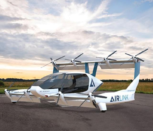
AMSL Aero has signed an order and received deposits for 10 of its Vertiia vertical take-off and landing (VTOL) aircraft, with an option for 10 more, from its first civil customer Aviation Logistics.
The company says Aviation Logistics could be flying 20 new Vertiia aircraft through its associated companies Air Link, AirMed and Chartair covering passenger services, aircraft charter, air freight and aeromedical flights from its seven bases across Australia from as early as 2027 (subject to regulatory approvals).
The deal marks a milestone for AMSL Aero and Vertiia, its passenger-capable hydrogen VTOL id the next generation of aircraft that takes off like a helicopter and flies fast and smoothly like a fixed wing aeroplane.
AMPV anti-drone prototype

BAE Systems successfully tested its Armored Multi-Purpose Vehicle (AMPV) Counter-Unmanned Aircraft System (C-UAS) prototype during a recent live fire demonstration.
As part of a collaborative effort with Moog, these positive results exemplify opportunities for future capability growth within the purpose-built modular framework of the AMPV platform.
The AMPV C-UAS prototype demonstrated the ability to accurately detect, track, identify, and defeat or disable stationary and moving aerial and ground targets.
AUKUS tests AI in Australia
Australia, the United Kingdom, and the United States have successfully demonstrated the integration of advanced autonomy and artificial intelligence (AI) to test the resilience of autonomous assets in a contested environment.
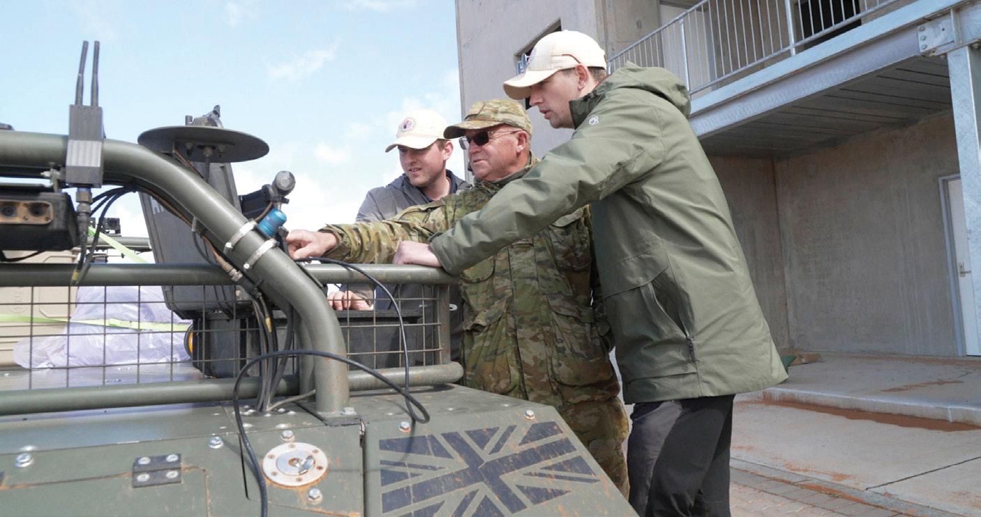
Conducted in South Australia in late 2023, the Trusted Operation of Robotic Vehicles in a Contested Environment (TORVICE) trial combined Australian, UK and US innovation and technology to test leading-edge AI in uncrewed robotic vehicles.
TORVICE tested the ability of autonomous vehicles to complete their missions and preserve network connectivity in a contested environment.
In December 2023, AUKUS Defence ministers announced that resilient and autonomous artificial intelligence technologies would be integrated into national programs in 2024.
The TORVICE trial takes us a step closer to adopting these technologies in the land domain.
The trial comprised UK and US robotic ground vehicles to represent autonomous multi-domain launchers and uncrewed ground vehicles, tasked to conduct longrange precision fires and other associated missions. The vehicles carried no weapons during the trial.
Australian scientists subjected the vehicles to attacks from electronic warfare, electro optical laser, and position, navigation and timing systems to test resilience.
Through AUKUS, Australia, the UK, and the US are collaborating to accelerate collective understanding of AI and autonomy technologies, and how to rapidly field robust, trustworthy AI and autonomy in complex operations.
New MD for Boeing Defence
Boeing has named Amy List as managing director of Boeing Defence Australia (BDA).
She succeeds Scott Carpendale who served as both vice president and managing director of BDA and vice president of Government Services for the Asia-Pacific region since 2022. Mr Carpendale will now focus entirely on the Asia-Pacific portfolio.
Ms List will be based at Boeing Defence Australia’s head office in Brisbane and report to Mr Carpendale.
She will also serve as a board member of Boeing Australia Holdings and a member of the Boeing Australia leadership team led by Boeing Australia, New Zealand & South Pacific president Maria Fernandez.
“Amy has more than 20 years of military and Defence industry experience, including engineering and operational service in the Royal Australian Air Force,” said Scott Carpendale, vice president of Boeing Government Services – APAC Region.

“This includes four years leading our Sustainment Operations portfolio which delivers key products and services such as AH-64E Apache, CH-47F Chinook, Helicopter Aircrew Training System, F/A-18F Super Hornet and EA-18G Growler to our customers.”
News | Defence & Aero 14 | March 2024
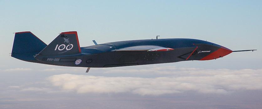
Ghost Bat takes off with more funding
An additional allocation of $399 million has been provided by the Federal Government for the ongoing development of the MQ-28A Ghost Bat.
The MQ-28A Ghost Bat, known as a Collaborative Combat Aircraft (CCA), is being developed in cooperation with Boeing Defence Australia.
It is the first military combat aircraft to be designed, engineered and manufactured in Australia in more than 50 years.
An entirely new technology, it is designed to act as a loyal wingman which will be able to protect and support our military assets and
pilots and undertake a wide range of activities across large distances, including performing combat roles.
The Government is now moving forward with the next stage of the program, including delivery of three Block 2 aircraft which have an enhanced design and improved capabilities.
This funding boost will enable a focus on developing sensor and mission payloads, an
Defence manufacturers receive grants
The Federal Government is investing $3.4 million in innovative Australian businesses to support the delivery of cutting-edge defence capabilities while creating highly skilled jobs and boosting local manufacturing.
The latest round of the Defence Global Competitiveness and Sovereign Industrial Capability Priority programs will provide 50 percent matching grants to 10 businesses, creating more than 50 jobs and helping to drive exports.
The latest recipients are:
• Aerobond (SA)
• Hendon Semiconductors (SA)
• U-Neek Bending Co (VIC)
• Advanced Navigation (NSW)
• Advanced Power Drives (NSW
• Protonautics (QLD)
• Jehbco Manufacturing (NSW)
• Armor Australia (NSW)
• Droneshield (NSW)
• JTM Gaskets (SA)

integrated combat system and autonomous systems.
More than 70 percent of the MQ-28A Ghost Bat delivery program is being directed towards Australian industry content, delivering substantial benefits to local companies and their highly skilled workforces. The company is aiming to have Australian production capability of the Ghost Bat within the next three years.
Autonomous capability for
the army
BAE Systems Australia and Trusted Autonomous Systems (TAS) have moved a step closer to delivering a next generation autonomous capability for the Australian Army.
The companies recently completed a four-year research and demonstration program during which they developed an advanced Artificial Intelligence (AI) system that could be used in uncrewed ground vehicles (UGV).
The TAGVIEW (Trusted Autonomous Ground Vehicles in Electronic Warfare) system would allow multiple UGVs to operate simultaneously to carry out mission objectives while identifying and evading potential threats.
It can feature a range of technologies, including optic cameras, LiDaR (Light Detection and Ranging) and internal navigation and route planning systems, making it easier for the user to control.
VTE | 15 www.saea.com.au Defence & Aero | News
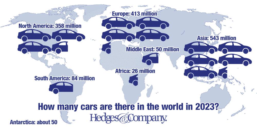
New Zealand has the most cars per capita in the world
There are about 1.475 billion vehicles on Earth in 2024. About 19 percent of those vehicles are in the United States.
Most of the cars in the world are in Asia/ Oceania, this area has more than a third of all vehicles on this planet. Many people think of North America as obsessed with cars, but North America is in third place. Europe, in second place has 28 percent of the world’s vehicles while North America only has 24 percent.
The average age of passenger cars in the US will hit 13.7 years in 2024. Hedges & Company is projecting the average age of passenger cars at 14.5 years by 2029. By contrast, the average age of passenger cars in Europe is 12.3 years in 2024 (European Automobile Manufacturers’ Association).
About 23% of all passenger cars on the road today are 20 years old or older. The most vehicles on the road today are model years 2015 to 2019, which make up approximately 26 percent of all vehicles.
The number of cars and trucks in the world, broken down by world region.
1. Asia/Oceania: 543 million vehicles on the road
2. Europe: 413 million vehicles (288 million in EU plus 125 million in non-EU countries)1
3. North America: 359 million vehicles
4. South America: 84 million vehicles
5. Middle East: 50 million vehicles
6. Africa: 26 million vehicles
7. Antarctica: about 60 vehicles
Here is a breakdown of vehicles per capita by world region.
1. North America: 0.71 vehicles per capita/710 vehicles per thousand people
2. Europe: 0.52 vehicles per capita/520 vehicles per thousand people
3. South America: 0.21 vehicles per capita/210 vehicles per thousand people
4. Middle East: 0.19 vehicles per capita/190 vehicles per thousand people
5. Asia/Oceania: 0.14 vehicles per capita/140 vehicles per thousand people
6. Africa: 0.06 vehicles per capita/58 vehicles per thousand people
7. Antarctica: 0.05 vehicles per capita/50 vehicles per thousand people
Two major countries are virtually tied for the most vehicles per capita in the world: The car-crazy United States and New Zealand. In both countries there are about 0.9 vehicles for every person.
On the other end of the scale are Pakistan, Vietnam, the Democratic Republic of Congo, Ghana and Kenya. These countries have 0.03 vehicles per capita, or less.
Here are the top countries for vehicles per capita and GDP per capita, revised for 2024:
1. New Zealand: 0.90 vehicles per capita/895 vehicles per thousand people
2. United States: 0.89 vehicles per capita/890 vehicles per thousand people
3. Estonia: 0.82 vehicles per capita/821 vehicles per thousand people
4. Cyprus: 0.79 vehicles per capita/785 vehicles per thousand people
5. Luxembourg: 0.78 vehicles per capita/784 vehicles per thousand people
6. Australia: 0.77 vehicles per capita/772 vehicles per thousand people
7. Canada: 0.77 vehicles per capita/770 vehicles per thousand people
8. Italy: 0.76 vehicles per capita/757 vehicles per thousand people
Iceland: 0.72 vehicles per capita/720 vehicles per thousand people
9. Poland: 0.60 vehicles per capita/604 vehicles per thousand people
10. France: 0.60 vehicles per capita/599 vehicles per thousand people.
The information in this article was from Hedges & Company www.hedgescompany.com

16 | March 2024 News | Overseas
Ampol takes charge
In days gone by, super and standard petrol, or diesel were commonplace at the bowser, then fuels became more sophisticated, replaced by PULP 98 and 95, ULP 91, E10 and even premium diesel. Now those fuels are being complemented by new forms of energy as more and more electric vehicles appear on the roads.
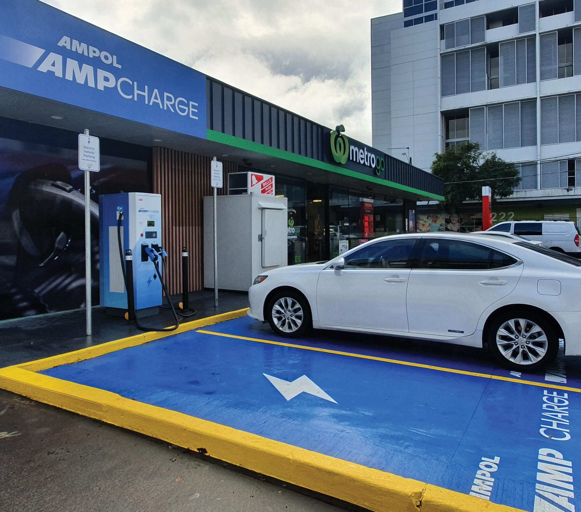
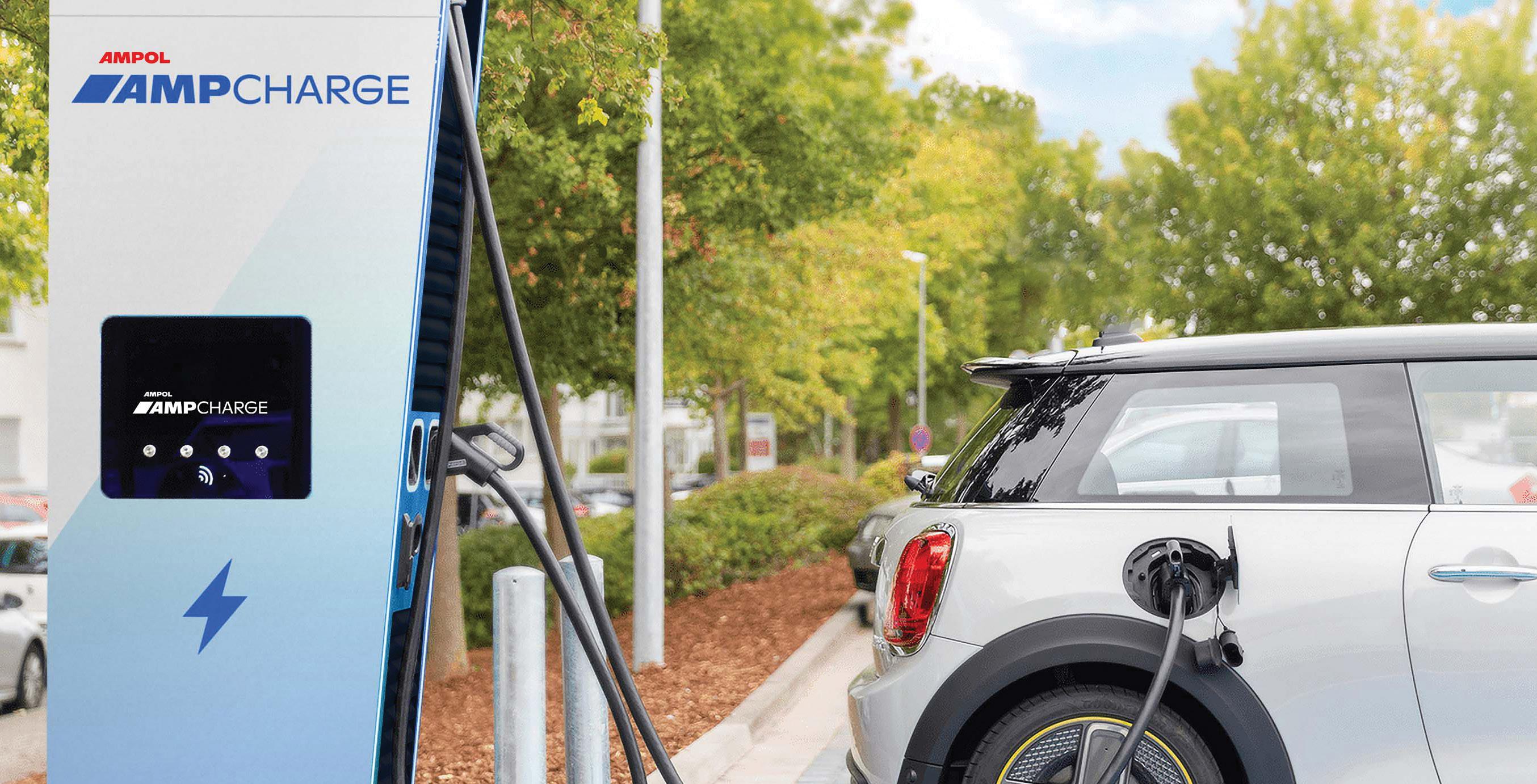
Petrol stations don’t just offer petrol anymore, with companies like Ampol converting their forecourts to cater for today and for the future with electric vehicle charging.
But Ampol is not only looking at electrification. Last year they entered into a partnership with US company OneH2 as its Australian representative.
Ampol, Executive General Manager, International and New Business, Brent Merrick said the partnership with OneH2 was a natural extension to Ampol’s fuel portfolio.
“We are excited to partner with OneH2 and expand our role in the hydrogen space, as we continue to work to deliver safe, reliable, and convenient future energy solutions for customers,” Mr Merrick said. “Hydrogen has a key role to play in reducing emissions across Australia’s transport and broader energy sector and offers a unique opportunity to decarbonise hard to abate heavy transport and heavy machinery sectors.
“We expect early hydrogen adoption within heavier vehicle fleets and operations who will benefit from short refuelling times and longer range compared to current battery electric alternatives.”
Prior to that, Ampol joined with Hyundai Australia, Pacific Energy and Toyota Australia in a Memorandum of Understanding (MOU) to develop hydrogen refuelling infrastructure. Hyundai and Toyota both have fuel cell electric vehicles. The goal of this MOU is to combine the expertise and capabilities of each partner.

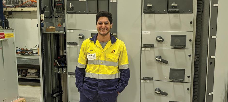
Expertise that Ampol is also developing with its graduate program, employing young engineers like Matt Brescia who has been with the company for two years, he started in February 2022 after completing his Bachelor of Electrical Engineering Honours at Macquarie University in Sydney.
Mr Brescia has been working across two very different teams, Energy Solutions and Distribution.
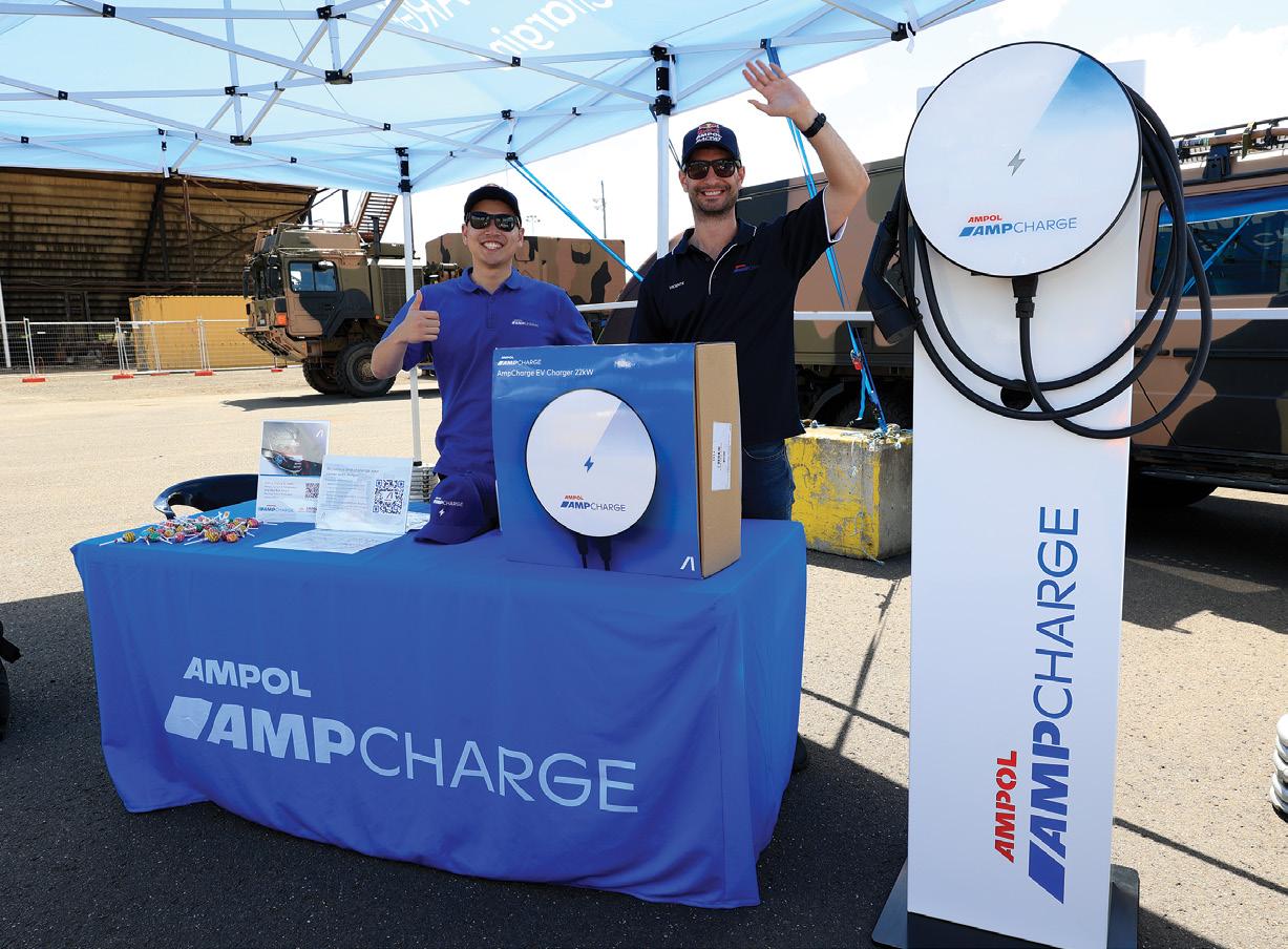
“Within Energy Solutions, I have been working with the e-mobility and generations teams, so I was involved in the AmpCharge EV charging rollout, and then any associated generation assets,” he explained.
“At the moment I am working in the electrical team in Distribution, where we maintain and operate the infrastructure that runs the movement of fuel around our terminals.” Mr Brescia is currently based at Ampol’s Kurnell Terminal in New South Wales.
“These areas always interested me, something fuels related but also looking to the future of energy and the energy transition. That was a big part of looking for a position out of university. I was looking for a
18 | March 2024 Feature | AMPOL

company that was leading the charge or active in that space. That’s why Ampol really appealed to me.”
Mr Brescia has been involved in the roll out of Ampol’s electric vehicle charging network – AmpCharge – and was involved with the first AmpCharge site in Australia.
“It was really great to see it all come to life. I joined Ampol before the EV chargers were open to the public, so we were still designing, still working out the details, and then launching them. Then I was also able to see them go live to the public,” he said.
“I was able to shadow experienced people, other engineers, as well as other designers that were part of the team. So I got to learn from them and bounce ideas off them. I was able to contribute as well and actually provide deliverables – it was a good mix.”
Mr Brescia’s main interests at university centred on the renewable energy and micro grid spaces on which he completed his research. The work with Ampol has provided a good intersection between what he studied, his interests and his work.
Mr Brescia has enjoyed working in different departments and teams as part of Ampol’s two-year graduate program. The next chapter for him is a more permanent role within a specific area at Ampol, which he says will be mainly in the renewable assets space.
“I definitely think Macquarie prepared me as well for the world of work, but there’s really no substitute for practical experience in the field which is what Ampol has offered me,” Mr Brescia said of his graduate experience at Ampol.
“Seeing both sides – renewables and fuels distribution – I’ve definitely gained a lot more experience in the past two years.”
Mr Brescia was part of the rollout of the AmpCharge EV charging network in 2022 and 2023, with 82 charging bays at 36 sites in Australia, delivered with the support of government grants. The network is expected to extend to 300 charging bays in Australia and 150 charging bays in New Zealand by the end of 2024 to provide Ampol with the flexibility to adapt to the evolving energy transition.
“The on-the-go public fast charging network rollouts are progressing in both Australia and New Zealand. And we’ve established our first major agreement with Mirvac to provide fast charging at their shopping centres.” said Ampol CEO Matt Halliday.
“We’ve also entered our first back-to-base charging arrangements with B2B customers. In both cases, we’re expanding off our forecourts to extend the strength of our e-mobility network for the future and in turn connecting customers back into our on-the-go network.
“It’s early days but the stats we’re seeing are encouraging in terms of both average charge time and duration.
“You can see the dwell time is circa 25 to 30 minutes, even for fast chargers and we continue to work on the convenience offering to benefit from the opportunity this presents for our retail businesses.”
VTE | 19 www.saea.com.au AMPOL | Feature
Take a seat …
When five seats are not enough
For the first time in 28 years a Ford topped the sales chart in Australia in 2023 but it was a ute – the Ford Ranger, it also beat another ute the Toyota Hilux that had held that spot for seven years. In fact, the three best-selling vehicles in Australia last year were utes; Ford Ranger sold 63.356 units followed by the Toyota Hilux at 61,111 and Isuzu Ute D-Max with 31,202 sales.
Quite obviously they are extremely popular but for some families they are limiting with at best a capacity to seat five in a dual cab –admittedly only around five percent of families have more than three children, but those five percent are restricted to buying vans. That’s limiting in many respects, one is the van’s ability to tow or to double as a work vehicle.
John Wilson is a long-time mechanical engineer with a Bachelor of Engineering Honours (Mechanical) from the University of New South Wales, which he followed with a Master of Engineering degree, and he is a long-time member of the SAE-A. He had a request two years ago from a customer with a Silverado who wanted to travel around Australia and needed more seating. That led to his designing and producing a new second row bench seat that could seat four.
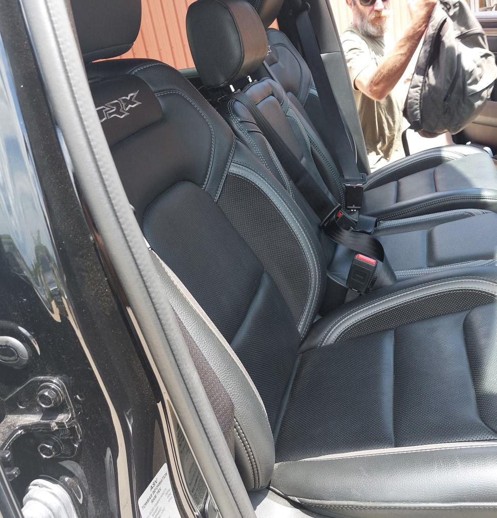
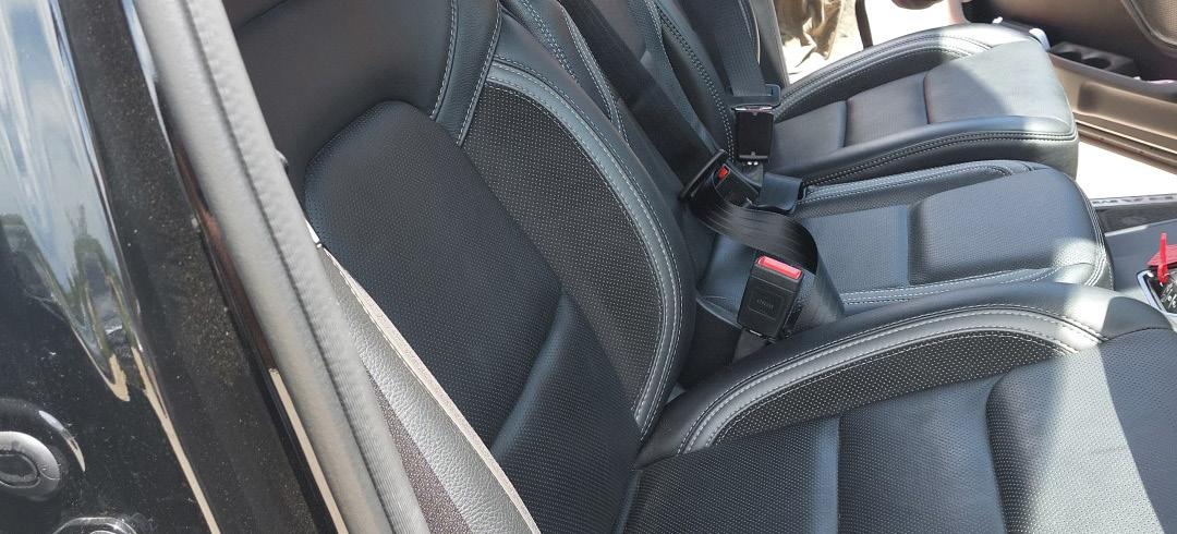
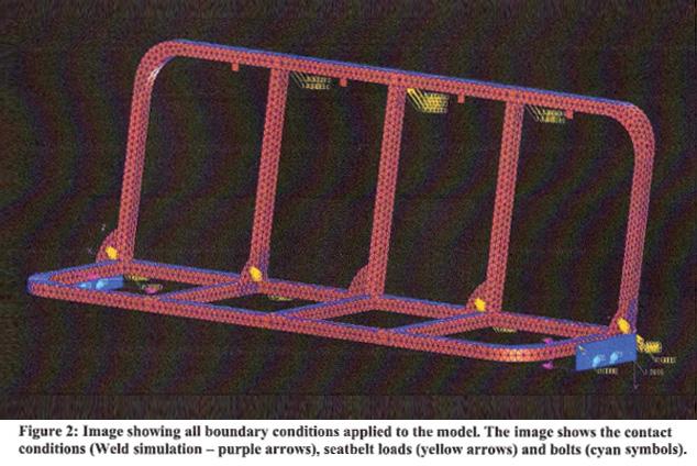
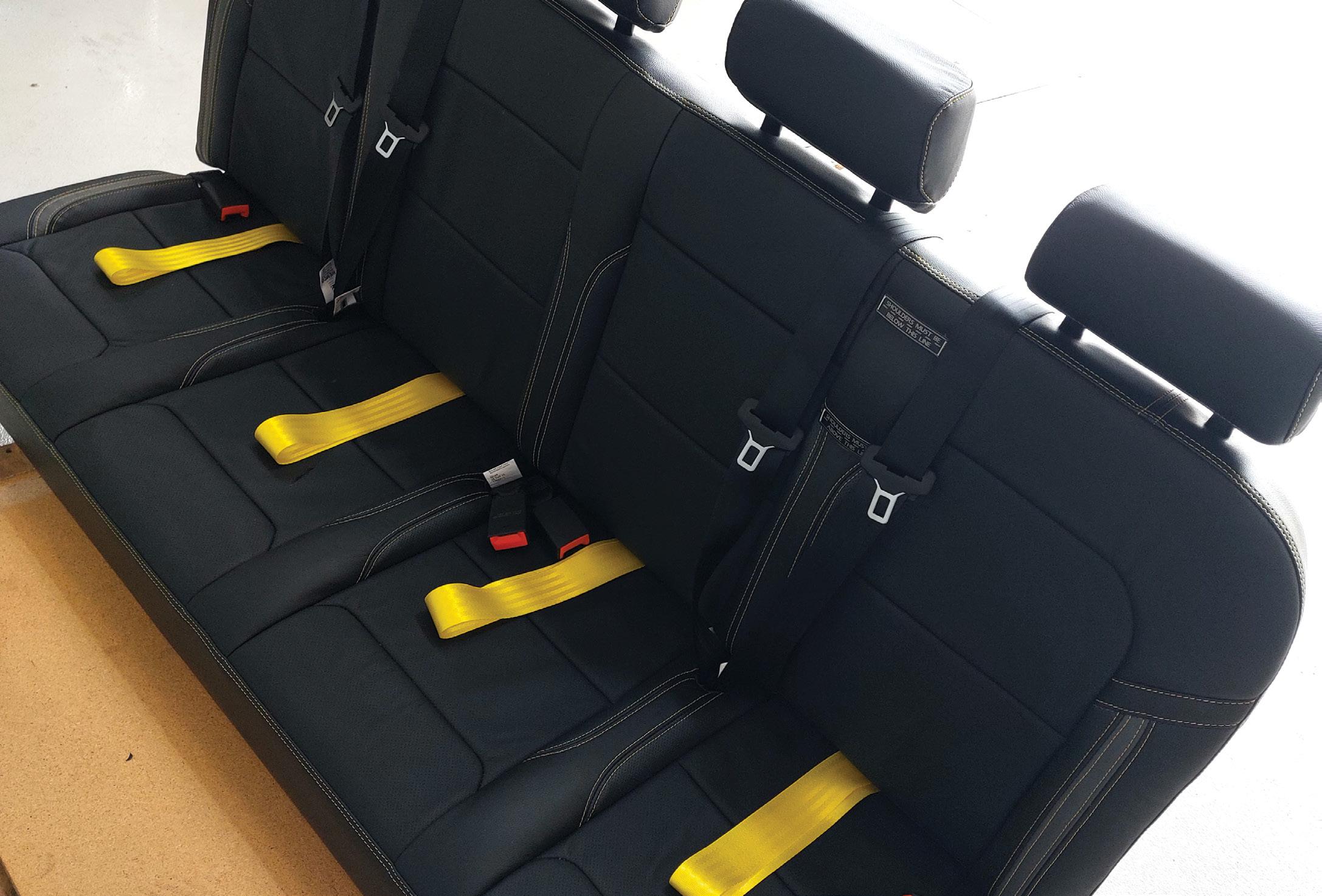
As an engineer his sights were set firmly on producing an Australian compliant seat that met the strength test associated with VFB5 and was equipped with the required seatbelts and child anchor points. These replacement seats allow four seating positions for kids, with four child anchor points and two ISO FIX baby seat capture points.
“I was up until recently a vehicle certifier in New South Wales and a certifier in the ACT,” Mr Wilson said, so he knew exactly what was needed. His good work was being noticed and he started to get inquiries and since then he has made these seats for a number of different utes and even for the Toyota 300 Series LandCruiser.
20 | March 2024 Feature | AKZ Seat
Mr Wilson designs and manufactures the seats and can also install them, moving around the country as needed. “We do offer a service where either myself or my business associate will check off, go to WA or whatever, make sure it’s been installed properly,” he said. “And then we give them the appropriate paperwork that allows whatever authority or engineering certifier to sign off on the evidence and the seat.”
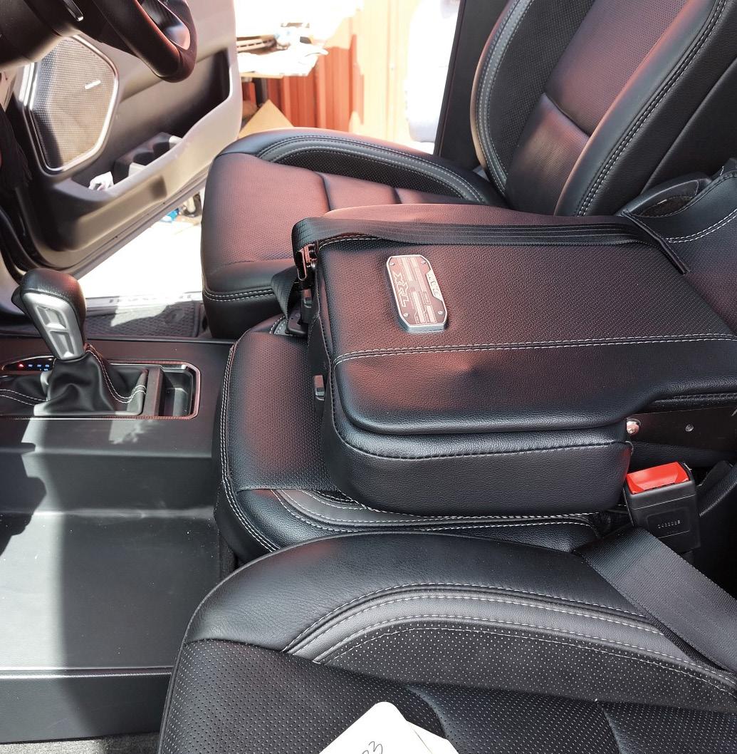
Word travels fast and just before Christmas last year he was approached by a person with a Dodge Ram who wanted to have a pop-up adult seat designed and fitted in place of the centre console in the front of his vehicle and for safety fitted with a lap sash seat belt. In a Dodge Ram this is possible as the TRX model has a very large centre console.
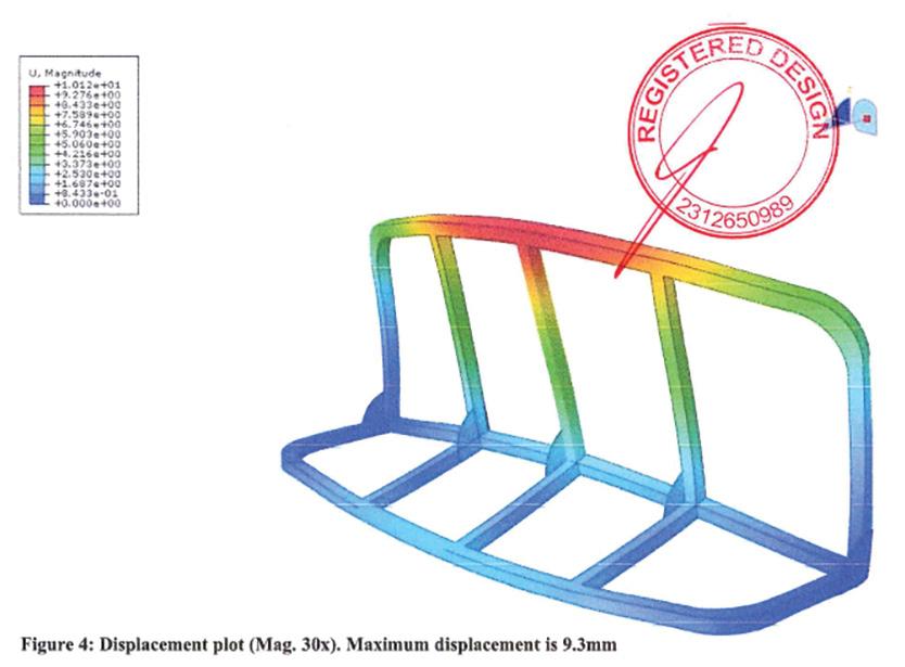
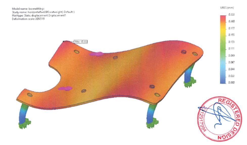
“A lot of effort goes into them and with the centre console, there’s a lot of engineering considerations to get that right,” Mr Wilson explained. “The stress analysis of the forces that are experienced that require certification, that’s ADR5. There’s the consideration of the seat belts, which is ADR4, and there’s a consideration of the seat anchor points, because the seat fits in and it’s bolted into the vehicle, so that’s ADR3.”
Not only is there a significant amount of engineering that goes into designing and making the seats, but Mr Wilson is acutely aware of maintaining the integrity of the interior design of the vehicle and each seat is custom made to match interior trim colours and materials.
So, while Mr Wilson’s company is a small concern his engineering and design expertise is not, and neither is his can-do attitude.
For more information visit https://vehicleengineering.com.au/
VTE | 21 www.saea.com.au AKZ Seat | Feature
Hydrogen Dreams
BMW puts its hydrogen dreams to the test
When one of the largest car companies in the world, Toyota, puts its faith, money and substantial engineering force into developing a hydrogen car – the Mirai, the world takes notice.
Then when one the world’s other engineering-driven car companies, BMW, does the same, it’s time to sit up and take notes not just notice.
Certainly, there are other well-known car companies also developing hydrogen cars like Hyundai and Honda, and some not so well known like Rasa, and US Hyperion Motors.
But when BMW puts their foot to the hydrogen pedal it means business, in more sense than one.
“Hydrogen is the missing piece of the puzzle for emission-free mobility because one single technology will not be sufficient to make climate-neutral mobility possible throughout the world,” said Oliver Zipse – Chairman of the Board of Management of BMW AG.
Piloting the hydrogen fleet
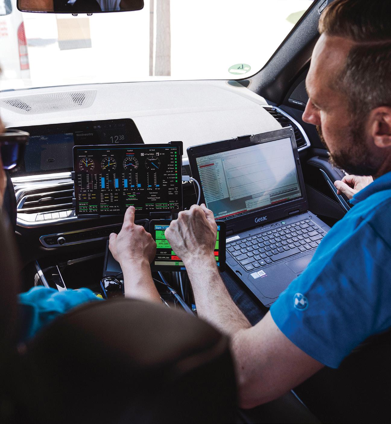
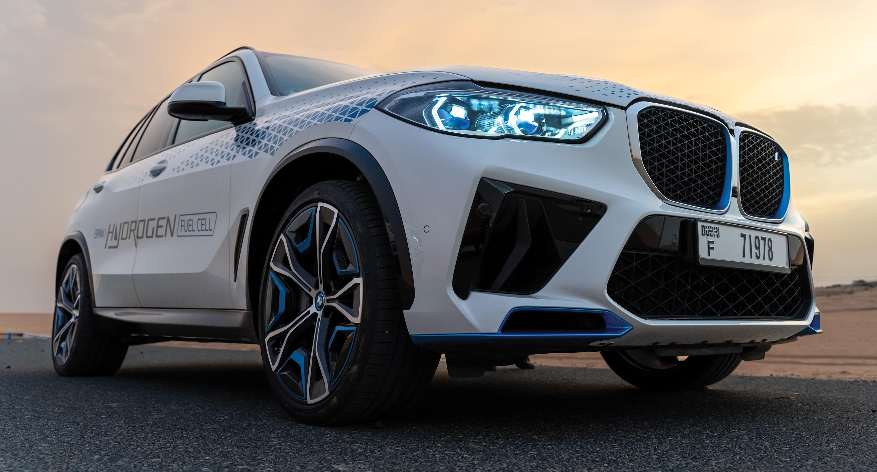
So far BMW is testing with a pilot fleet of BMW iX5s launched recently, these have already completed an intensive round of hot-weather testing in the UAE.
BMW stated that its highly efficient fuel cell system, that is the two hydrogen tanks, the electric motor and the power battery teamed up with the central vehicle control unit demonstrated outstanding performance.
The Munich-based development team examined the functionality of all the electric systems under extreme conditions and the ability of the cooling power to enable the full performance of the vehicle.
Vehicles from the pilot fleet are now in action in Europe, Japan, Korea, China, the USA and the Middle East, and they may come to Australia this year.
The aim is to shine a spotlight on the everyday usability of hydrogen-powered vehicles, and beyond that to gain important knowledge for the development of a potential series-produced model.
The BMW Group is also using the pilot fleet to provide support for the development of a refuelling infrastructure, which can be used with 700-bar refuelling technology across all categories of vehicle from passenger cars and small vans to buses and heavy-duty commercial vehicles.
22 | March 2024 Feature | BMW Hydrogen
What’s under the bonnet
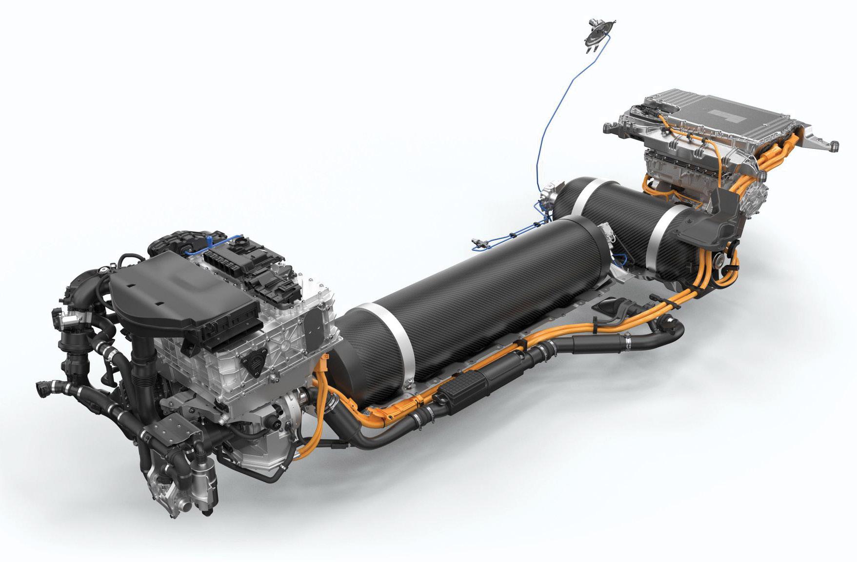
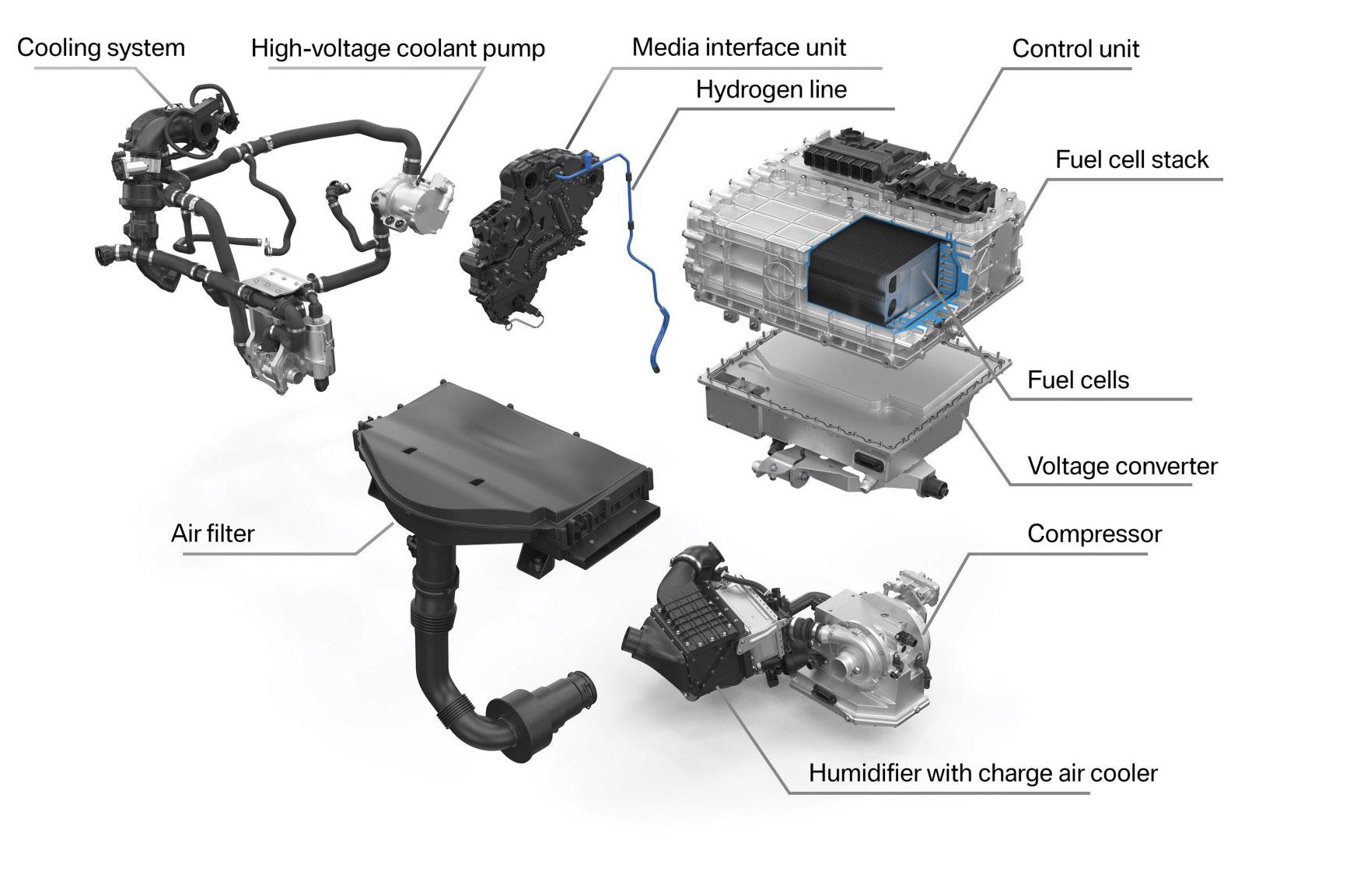
The BMW iX5 Hydrogen has a fuel cell system generating an output of 125 kW. BMW obtains the individual fuel cells from the Toyota Motor Corporation. The cells are an integrated drive unit using fifth-generation BMW eDrive technology (the electric motor, transmission and power electronics are grouped together in a compact housing). The total output of the drive system is healthy 295 kW.
The hydrogen needed to power the fuel cell is stored in a pair of 700-bar tanks made from carbon fibre-reinforced plastic (CFRP). Together, these tanks can hold around six kilograms of hydrogen. This storage capacity gives the BMW iX5 Hydrogen a range of around 500 km in the WLTP cycle.
The vehicle top speed is 185 km/h and it can sprint from 0 to 95 km/h (60mph) in just six seconds. The 400-volt battery situated directly above hydrogen engines increases the iX5’s power.
The BMW Group has developed special hydrogen components for the new fuel cell system to complement technological analogies to the combustion engine such as the intercooler, air filter, control units and sensor technology.
These include a high-revving compressor with turbine or a high-voltage coolant pump.
When and what model BMWs
It has been reported that the BMW iX5 Hydrogen is one of three hydrogen-backed vehicles coming to BMW in 2024 but this has not been substantiated, and it is doubtful this would apply to Australia where the hydrogen infrastructure is still in its infancy.
In fact, BMW has said of it hydrogen vehicles that: “we envisage potentially offering our customers a production vehicle in the second half of this decade”.
CarsGuide has reported that a small fleet of hydrogen fuel-cell vehicles will be in Australia this year. According to CarsGuide three iX5s will take a six-month tour of Australia as part of the test program.
“We plan to showcase the cars and technology to our staff, the media, government officials and students.
“The aim is to put the spotlight on the everyday usability of hydrogen-powered vehicles in a country where hydrogen has the potential to play a key role in fulfilling future renewable energy requirements,” BMW Group Australia Product and Business Communications Manager, Nick Raman told CarsGuide.
Hydrogen offers huge benefits over electric vehicles with quick refuelling, with similar times to petrol or diesel, and the vehicle’s long range makes it so much more attractive in countries like Australia and the US.
Despite the obvious advantages of hydrogen fuel the technology is struggling to be a blip on the car sales radar in Australia with just six hydrogen fuel cell vehicles sold in 2023, all Toyota Mirais.
Even globally sales are slow with just 72,000 in 2023, in a market of around 80 million vehicles.
VTE | 23 www.saea.com.au BMW Hydrogen | Feature
The Future is on show at the Australian Auto Aftermarket Expo
The Australian Auto Aftermarket Expo, run by the Australian Automotive Aftermarket Association, is one of Australia’s largest industry events, with a comprehensive collection of automotive brands, training, tools, technology and experts.
The aftermarket is also one of Australia’s leading employers of engineering talent. This year the Expo will take place from 11 – 13 April in Melbourne and entry is free to members of the SAE-A.
“Addressing the theme the ‘Future is Here’, the Australian Auto Aftermarket Expo has secured experts from across Australia and across the globe to provide the very latest information and practical tips so that you can navigate these challenges to not only survive but thrive by taking advantage of the many opportunities that will arise as our industry changes and adapts to this new reality,” Stuart Charity, Chief Executive Officer of the Australian Automotive Aftermarket Association said.
“This free to attend Expo will feature more than 400 leading brands showcasing the latest vehicle technologies under one roof and will deliver a comprehensive education program and with thousands of industry decision makers in attendance. It provides an unrivalled networking opportunity and is a must attend event for automotive engineers and undergraduates.”
There are a host of features that make this a worthwhile event for engineers, apart from the chance to see all the best products the industry has to offer as there are more than 400 local and international automotive
brands showcasing products and services across 21,000sqm of floor space. A good look around will take most of the day. This year the AAAExpo will host the return of the International Pavilion that will allow Expo visitors to connect with suppliers not only from across the country, but from across the globe.
Apart from visiting the trade stands, and this is a trade only event, there is a business education program that will feature leading local and international industry experts, including special guest Bill Hanvey, president and CEO of the Auto Care Association (US). The program will provide advice on topics to improve business performance and adapt to technological changes.
A Technical Training Program will be run with training led by international experts Diagnose Dan from the ‘Diagnose Dan’ YouTube channel, and Sean Tipping, host of the Automotive Diagnostic Podcast in the US.
The special program will train attendees on the most in-demand and challenging automotive diagnostic areas. This program will run across four days, beginning Wednesday 10 April, a day before the official opening of the Expo on Thursday 11 April. There are costs of $195 attached to attending each training session which run for four hours.
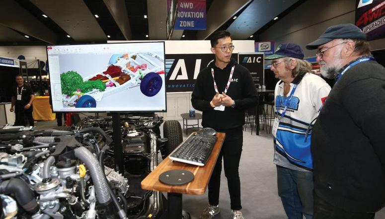
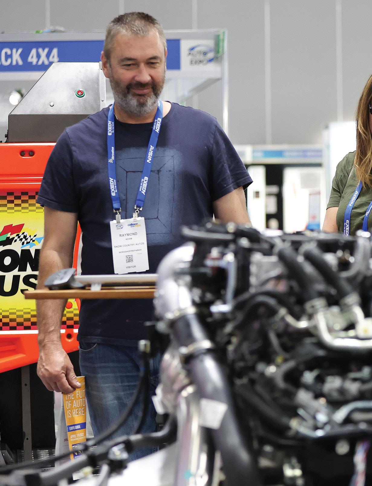
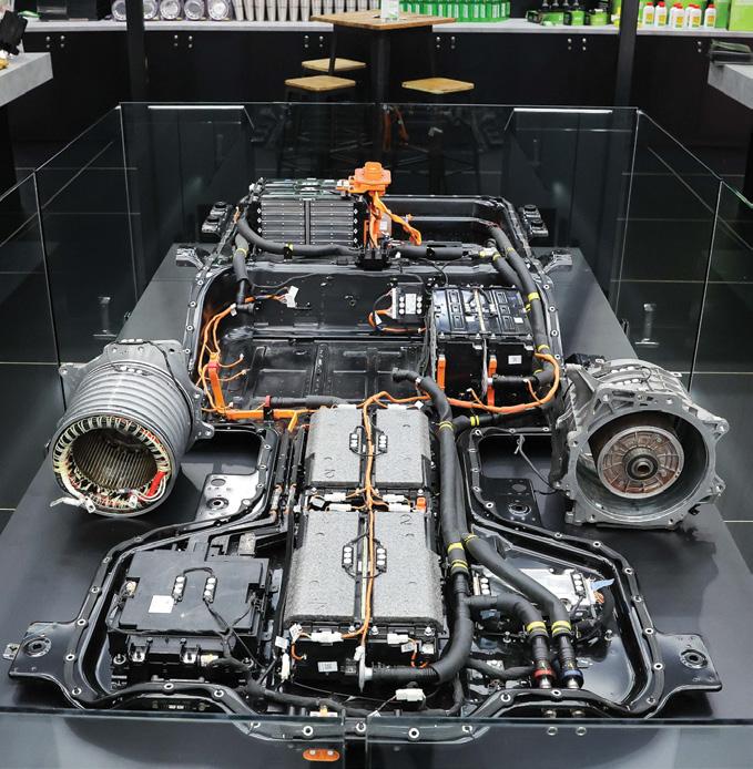
To cater for the changing auto landscape the Expo has an ‘Electrified Zone’ to train, diagnose and service EV and hybrid vehicles, and an ADAS (Advanced Driver Assistance Systems)Technology Zone with the latest information related to ADAS calibration, featuring demonstrations led by experts, free advice, and the latest equipment. The Electrified Zone is designed to give attendees exposure to the latest in EV technology and techniques, the Zone will also feature the latest in EV tools and workshop equipment, EV Personal Protective Equipment (PPE), and display a Ford F-150 Lightning EV, provided by the Auto Innovation Centre (AIC). Sessions featuring electrified demonstrations are on each day, four on Thursday and Friday and three on Saturday.
“The automotive industry in Australia is undergoing unprecedented change driven by the complexity of the car parc, rapid changes in vehicle technology, the transition to zero and low emission vehicles, changes in industry dynamics as well as the changing capabilities and needs of our workforce and customers,” Mr Charity said.
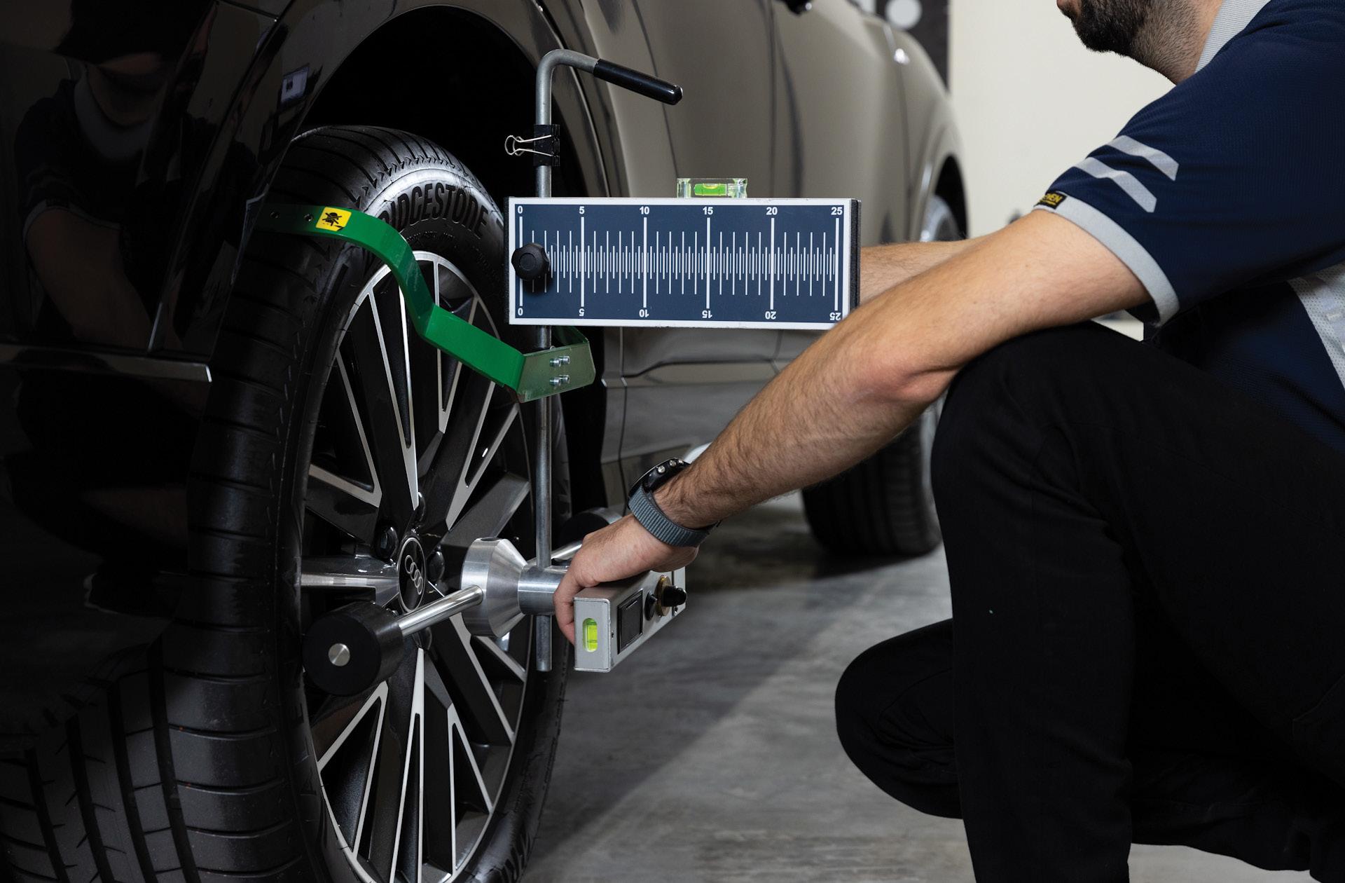
The ADAS zone will feature dedicated seating and a stage, which will showcase the latest ADAS equipment and calibration techniques from a variety of suppliers.
Feature | AAA Expo 2024 24 | March 2024
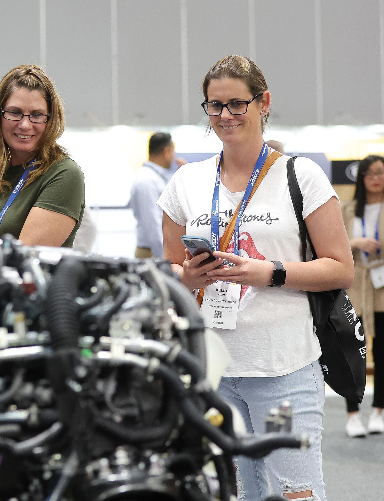
The zone will provide ADAS calibration demonstrations, training and specialist advice focused on best practice. In order to facilitate interaction and networking there is a free networking event at the show on 12 April from 4.30pm to 6pm inside the Expo where you can meet with industry colleagues.
The AAAExpo takes place at the Melbourne Convention and Exhibition Centre, and since it is a trade only event, entry is restricted to members of the automotive industry and tertiary students including engineering students over the age of 16.
You can register for the Auto Aftermarket Expo at www.autoaftermarketexpo.com.au
All visitors must register and if you wish to attend the Technical Training Program, you must purchase a ticket separately.
You can register online or onsite however, to avoid queues we recommend you preregister.
This will ensure you receive approval prior to attending and receive registration confirmation for easy entry.
When registering, full company details
or university details must be entered. If you enter online you will receive an email confirming your registration.
Students can also register to attend the Australian Auto Aftermarket & Collision Repair Expo via a dedicated Student Registration website. Please take your university or trade student identification with you to the event.
The Student Registration website is https://msegroup.eventsair.com/aaaecre/ students/Site/Register

VTE | 25 www.saea.com.au AA Expo 2024 | Feature
Thales offers graduate engineers an exciting future now
Thales offers a variety of internship, graduate and apprenticeship programs to help kick start your career whether you are a student or recent graduate.
This year the program opened in early March and closes on 15 April 2024 for the 2025 intake. The huge variety of industries and technologies that the business operates means that it can offer a range of opportunities to engineering graduates.
The early career programs reflect the global nature of the business, are country specific, and designed to work in harmony with the local education systems.
The Thales Graduate Program focuses on developing talented graduates to help deliver high technology solutions.
Beginning in February each year, and spanning 18 months in duration, the program consists of specialist on-the-job training and a variety of structured learning modules (both technical and non-technical).
Throughout the 18 months, graduates have the opportunity to learn about the wider Thales business, visiting sites Australia wide. The company aims to train graduates as experts in an area, as well as gaining valuable exposure to a wide range of Thales solutions.
To support you through this journey the company will provide you with a mentor from day one.
Thales is proud to be recognised in the Australian Financial Review Top 100 Graduate Programs and as one of the Top 10 Most Popular Engineering Employers.
Thales’ 18-month graduate program is focused on showing all the diverse and exciting aspects of its people and business hence the company is looking for the brightest from a range of engineering backgrounds including mechatronics, software, mechanical and electrical engineering, just to name a few.
While the company takes into consideration your study, what they really care about is your passion and willingness to learn and so looks for graduates who are eager to take responsibility, willing to speak up and provide business insights and display technical prowess.
Step 1: Head to the Thales GradConnection page au.gradconnection. com/employers/thales/jobs to submit an application (now open)
Step 2: Candidates the company feels could add to the Thales culture will be sent an online video interview. It’s a quick process which can be done at a convenient time for you. The video aims to get to know you better.
Step 3: You will be invited to attend an interview where you’ll learn more about Thales and be assessed both behaviourally and technically. This interview is equally an opportunity for you to gain an understanding of the Thales working environment and the manager who could be supporting you.
Step 4: If successful, Thales will conduct pre-employment checks (medical and police check) and then make an offer.
The company says its best applicants are able to articulate why they want to work at Thales and how this aligns with their passions, values and future goals.
The hiring managers will be particularly impressed if you have done your research on Thales and its current projects.
At Thales they practice behavioural based interviews. This means throughout the interview they will be looking for you to provide examples of real-life situations you have been in before. It’s important in this style of interview to not be hypothetical about what you would do but use examples from previous experience. You can use examples from work, internships, volunteering, sports, university involvement and particularly university projects such as Formula SAE.
Dependant on the type of role you may be presented with a simple case study or problem to workshop with the interview team. You will know before the interview if this will be part of the assessment.
Source and for more information visit:: https://au.gradconnection.com/ employers/thales/jobs/
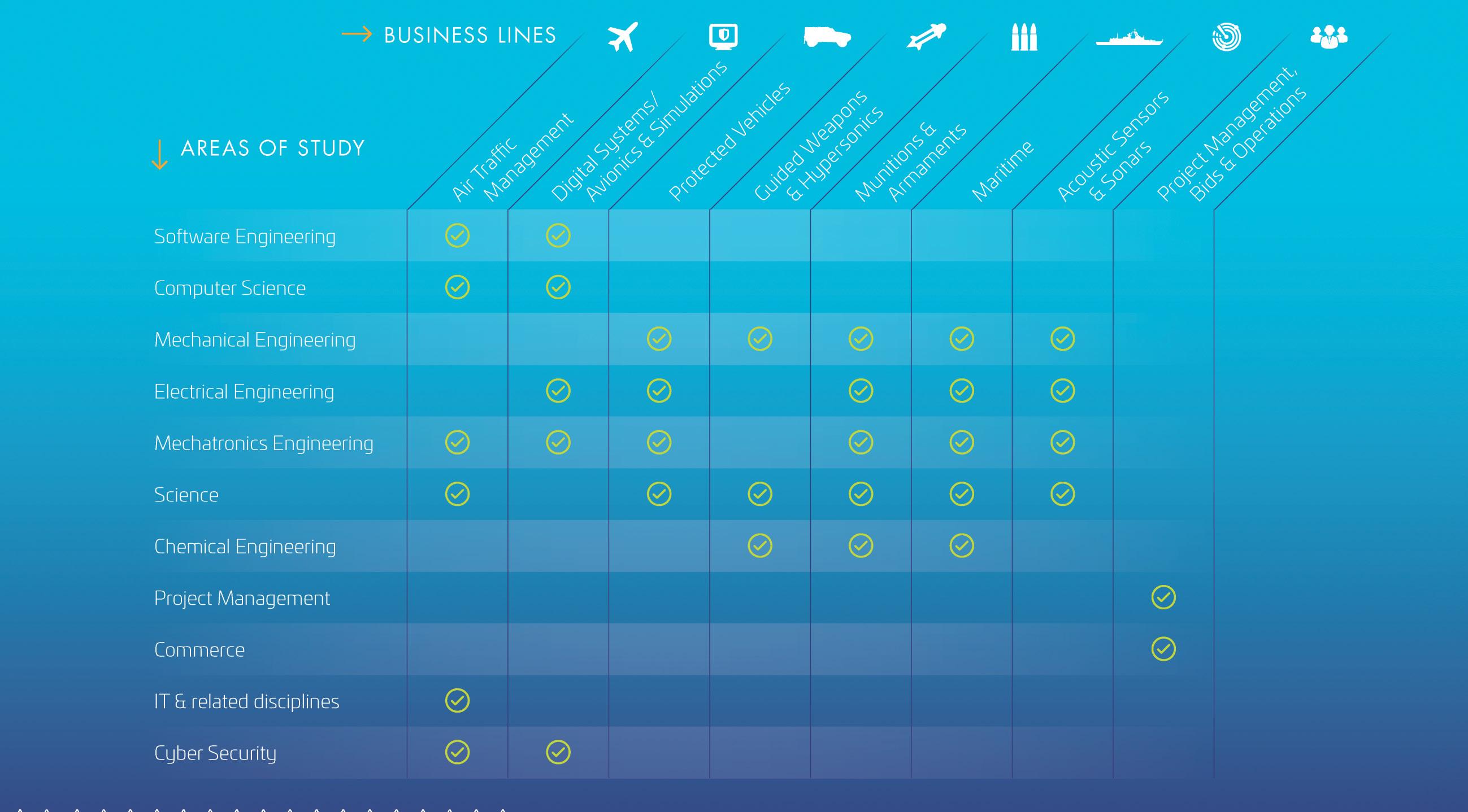
Feature | TAC
26 | March 2024
Lukas Laarmann1*[0000-0002-9647-1223], Lukas Welfens1, Thilo Röth1, Simon Watkins2, Mohammad Fard2
1 Department of Aerospace Engineering, FH Aachen, Germany
2 School of Engineering, RMIT University, Australia
* Corresponding author: s3677065@student.rmit.edu.au
Crashworthiness Review for Electric Vertical Take-Off and Landing Vehicles and Implementation of the Automotive Safety Approach
1. Introduction
The increasing energy density of high voltage batteries and further development progress in connectivity and digitization enables new vehicle concepts such as electrical vertical take-off and landing vehicles (eVTOL). The eVTOL industry is growing rapidly; according to Roland Berger’s study [1], more than 160.000 units will be part of air traffic by 2050. First services are announced for the Olympic Games in 2024. [2]
The industry is well aware of the lack of crashworthiness for the rising eVTOL mass market. NASA initiated 2021 a crashworthiness workshop to address this challenge. Publications of the DLR [3] and NIAR [4] highlight the need for further research regarding the integration of crashworthiness during the development process of eVTOL and the emergency landing condition standards. Novel propulsion and control systems, including high energy density batteries, create unknowns about post-crash risks, and novel vehicle architectures, seating arrangements, and urban environment operations may need novel safety concepts. Both [3] and [4] recommend implementing safety from the conceptual design stage and investigating the influences of novel aspects using simulation methods. Lowell Foster from GAMA [5] suggests planning on accidents and adapting the automotive industry approach. More about the automotive industry approach, here also referred to as the automotive safety approach, will be explained in section 2. Justin Little and Joseph Pellettiere from NASA/FAA [6] presented a full-vehicle crash test simulation to gain data and knowledge about the crashworthy performance of urban air mobility (UAM) vehicles and simulation capabilities.
2. Crash Safety
While aviation’s crash safety approach mainly focuses on active safety (crash prevention), the automotive safety approach often prioritises passive safety (crash mitigation), aiming for uninjured occupants in crash events. One key action to ensure and evaluate occupant protection via passive safety has been establishing standardised full-vehicle crash tests. Nowadays, full-vehicle crash tests are conducted by governmental organisations, private organizations, and vehicle manufacturers to evaluate legal, consumer protection, or manufacturer-
specific requirements. All tests are based on fundamental accident research, assessing the risk, and probability of occurrence vs. severity, including fatality.
2.1 Vehicle Measures
eVTOL are similar to helicopters in many ways but have distinct differences in technical aspects. Most manufacturers state that the safety of their eVTOL is ensured by a redundant flight system design. Redundancy of the flight system enables that even a failure of one or several rotors does not lead to a crash, and the vehicle can still perform a controlled landing. Another widely used safety feature on eVTOL is the accommodation of an emergency parachute system. Unlike helicopters, whose design, with a rotor located centrally above the fuselage, make installing an emergency parachute system difficult, the installation on eVTOL is less problematic, albeit increasing weight. Short take-off or at least landing (STOL) capability is another safety feature of some eVTOL with the possibility to perform conventional landing manoeuvres. The prerequisite is the presence of wings that generate sufficient lift, as well as a landing gear to enable rolling touchdowns. Information about passive safety measures concerning the structure or used materials is not yet published for the existing eVTOL concepts. However, it is expected that eVTOL’s crashworthiness will be based on a mix of requirements for helicopters and small airplanes, as EASA’s recent publications for VTOL certification (SC-VTOL [7, 8] & Means of Compliance [9–12]) point out. Due to the lack of eVTOL’s structural crashworthiness design concepts, the following section is a short review of relevant automotive crash design structures.
In automotive design, crash load requirements are a decisive development criterion. Early in the development phase, the crash concept, including the load paths and force levels, is defined. One essential function of the vehicle’s body structure is the protection of the occupants. A common structural approach to protect the occupants is a rigid life-cell around the occupants supplemented by energy-absorbing structures for the conversion of the kinetic impact energy. The life-cell is built by A-, B-, and C-Pillar connected with stiff roof and floor cross member. For front- and rear impacts, the main energy is absorbed by two longitudinal members, which run into
ABSTRACT
Due to operation in urban areas, air taxis compete, unlike most conventional aircraft, with individual transportation systems like cars and public transportation systems. Safety and comfort are important for potential air taxi customers. This work highlights the importance of eVTOL’s crashworthiness and introduces a development and evaluation approach. It is done by deriving eVTOL-specific full-vehicle crash load cases analogue to the automotive approach and introducing a corresponding crashworthy design concept, using an analytical approach supplemented by a multi-body-dynamic simulation. The multi-body-dynamic simulation confirms that the analytically developed crash concept fulfills the previously derived crash load case’s test criteria. In contrast, the simulation demonstrated that lumbar loads could exceed certification limits for an advanced crash load case with higher impact velocity.
KEYWORDS: eVTOL crashworthiness, safety, automotive safety approach, full-vehicle crash test
the rocket panels and centre tunnel. [13]
In racing situations, such as Formula One, drivers frequently survive extremely high crash loadings where cars use a monocoque design made of laminated composite sandwich materials. The outer layers are made of carbon fibre reinforced polymer (CFRP), which encloses a honeycomb structure in the core. The force level can be specifically adapted to the requirements via targeted material thickening. Additionally, Formula One cars use designs tailored to the single driver/occupant such as the “Halo” and a nose cone section for frontal impact protection.
3. Crash Impact Conditions
To develop appropriate passive safety systems, crash impact conditions must be identified. Therefore, accident events and causes are categorised to identify relevant crash scenarios and impact conditions. Future eVTOL accident events can be determined by two approaches. First, investigation of relevant air- and rotorcraft data and statistics, for example, commercially used small airplanes and helicopters, and second, approximations and predictions of accident events. These can be based on aviation accident data, (technical) failure modes, and -rates, but also on future eVTOL mission analysis and simulations.
Analysis of aviation accident events shows that the most frequent fatal crash scenarios result from loss of control - in flight (LOCI), controlled flight into terrain (CFIT), and runway excursion (RE). Further categories are system/component failure or malfunction (SCF), abnormal runway contact (ARC), and undershoot/overshoot (USOS). [14–16] One of the main references for aviation accident analysis is the 1985 published DOT/FAA/ CT-85 study [17] of the FAA, where 311 U.S. civil helicopter accidents from 1974 until 1978 were analysed regarding impact conditions and
www.saea.com.au Technical | Feature
VTE | 27
APAC-21-176
occupant injuries. The study identifies six crash scenarios: Vertical impact, longitudinal impact, rollover, wire strike, water impact, and high yaw rate impact. The vertical crash scenario was determined as the most hazardous. Engine failure or malfunction is, with 27 % of the 311 accidents, the most frequent accident cause. The study also represents the base of EASA’s recently published certification proposal (SCVTOL [7, 8] & Means of Compliance [9–12]) for future eVTOL in terms of crash requirements.
The certification proposal prescribes a minor emergency crash landing, which requests loads below 30 g at seat attachment level after a vertical impact velocity of 9,1 m/s, which covers slightly more than 95 % of the 311 survivable helicopter accidents. The requirement is also already known from helicopter certifications (CS-23.562 [18], CS27.562 [19], CS-29.562 [20]).
Analysing eVTOL missions, one of the most critical phases will occur during the transition phase from hover to cruise mode. Three main reasons are; the complex and undiscovered transition of lift mechanisms, the absence of kinetic energy in the vehicle system to operate a safe emergency landing, and altitudes below minimum altitudes for the safe activation of ballistic recovery systems [3, p. 5]. At the time of article writing, only a few aircraft are on the market that show transition phases, which is why data about the transition phase’s risk and resulting impact conditions is rarely available. Another critical phase will be the vertical takeoff and landing phase, according to aviation accident statistics. [21, p. 42] This is a flight phase, where passive safety shows high efficiency in terms of weight and economic aspects vs. safety benefits due to relatively low velocities compared to in-flight velocities.
Furthermore, low flight heights (300 – 500 m) cause a reduced reaction time to initiate an emergency landing and navigate to appropriate ground conditions.
The expansion of urban air mobility will increase the density of aviation vehicles in cities. This entails two significant safety risks; mid-air collisions, particularly during cruise mode, and emergency landings, with differing ground conditions from hard or soft soil.
In conclusion, engine failure and malfunction are the most frequent accident cause and are expected to rise, caused by the novelty of the technology [12, p. 5]. The most critical flight phases are the transition and take-off and landing phases. Vertical impacts are the most hazardous crash scenarios. Additionally, a rising quantity of vertical take-off and landing operations are expected for the UAM market with short-distance flights. Vertical crash impact conditions are therefore considered to be the most crucial crash scenarios and will be the focus of this work.
Vertical impact velocities differ for civil, navy, and army helicopters between 8 m/s and 13 m/s covering 95 % of accident events according to [22]. In the following work, simplified crash impact conditions with two levels of vertical velocity are defined. Vertical
crash 1 (VC 1), with a velocity of 10 m/s, which is slightly higher than current certification requirements, and a vertical crash 2 (VC 2), with a velocity of 15 m/s, covering 99 % of the in DOT/FAA/CT85/11 study [17] investigated helicopter accidents. (Figure 1) The crash impact conditions claim no general validity and do not consider roll, pitch, or yaw angle variations. Impact angles ranged between -5° up to +15° for pitch and +/-10° for roll angles, according to [23]. It is expected that control units will improve and be capable of keeping the vehicle, in most cases, in a level attitude with low longitudinal and lateral velocities. Longitudinal and lateral velocities are therefore expected to be very low and are not considered in this crash configuration. The crash scenario covers particularly accidents resulting from complications during the start- and landing phase, with the vehicle hovering.
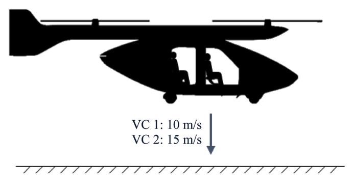
3.1 Requirements
To evaluate the system’s crashworthiness, load cases and criteria are reviewed and defined. Biomechanical load limits are used to assess and specify the consequences of a crash on occupants. Injuries are not only dependent on maximum achieved acceleration but also on the direction of action and the duration of the load. Even though biomechanical load limits can vary widely [24], in this approach, regulation requirements [11] and in-house definitions regarding accelerations and forces are used to evaluate crashworthiness. With a focus on vertical impacts, the most critical load occurs in the axial direction of the lumbar spine. [25] According to EASA’s certification regulations [11], the maximum lumbar load is required to be lower than 6674 Newton. The Eiband diagram (Figure 2) represents the basis for vertical acceleration evaluation. It shows an expected injury level depending on the acceleration value over the duration based on voluntary human exposures and animal experiments with hogs and chimpanzees.
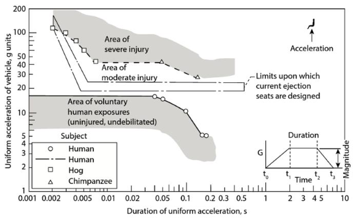
be considered. Two tests are established, the limit drop test (LDT) and the reserve energy absorption drop test (READT). In the former, the vehicle drops to the ground from a height of 0.33 m. In the reserve energy absorption drop test, a vehicle drop from 0.495 m is prescribed, and landing gear failure is not permitted. Failure is defined by the fact that, excluding the landing gear itself, no structures of the vehicle are allowed to touch the ground. For the LDT, a maximum occupant acceleration of 2 g is inhouse defined, while for the READT, 4 g is expected to be appropriate. For all load cases, the occupant’s acceleration is interpreted using the Eiband-diagram, and the limit of the lumbar load is set to 6674 N.
Furthermore, energy absorbing structures have to collapse in a controlled deformation sequence. Deformations should take place from the outside to the inside of the vehicle, excluding the seat console and airbag.
Table 1 shows an overview of the to-be-considered load cases, their characteristics, and criteria.
contact between underbody and ground.
4. Crashworthy Design Concept
The crash concept base is a rigid life-cell and energy absorbing structure. In the first conceptual crash design concept for eVTOL, a reduced mechanical system of four energy-absorbing systems is considered (see Figure 3). An airbag, deployed below the underbody, a landing gear, potentially interacting with the airbag, and a seat console. Between the seat console and the airbag is a further energy absorbing structure defined as passive structure.
The flight propulsion unit (FPU), including the wings, is assumed to be capable of decoupling from the people transport unit (PTU) via a predefined breaking point just before impacting the ground. Detailed construction limitations and principles are not the focus of this work and are not considered here.
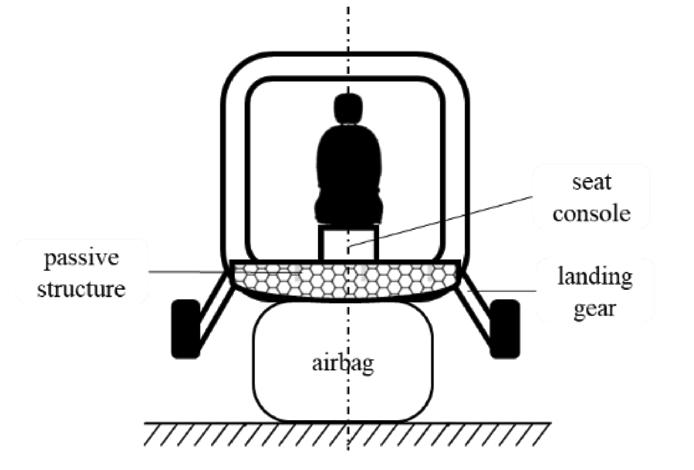
In addition to the crash load cases, legal regulations [28] for landing gear design must
28 | March 2024 Feature | Technical
Figure 1. Expected most important eVTOL crash impact condition - vertical crash
Figure 2. Biomechanical acceleration limits in vertical direction – Eiband-diagram [26, 27]
Figure 3. Abstract illustration of energy absorbing systems in vertical crash load case.
Load-Case Impact Impact Criteria Velocity Mass LDT 2,54 m/s 3000 kg Acceleration in vertical direction av < 2g; No plastic deformation. READT 3,12 m/s 3000 kg Acceleration in vertical direction av < 4g; No
VC 1 – Acceleration in vertical Low 10 m/s 1200 kg direction in area of Speed moderate injury based VC 2 – on Eiband-diagram; High 15 m/s 1200 kg Max. axial lumbar load Speed F < 6674 N
Table
1 Load-Case
Overview - Characteristics and
Criteria
The complex technical system is reduced into a simplified mass-spring-damper model for a better understanding of following investigations. Figure 4 shows the significant representative masses of the four passengers, seats, the vehicle structure, the landing gear, and the energy absorbing systems in the form of spring-damper symbols for the seat console, the passive structure, the landing gear, and the airbag. The variable x1…5(t) represents the displacement dependable on time for each mass.
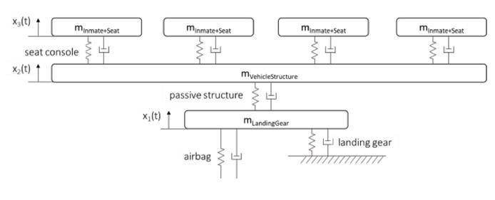
4.1 Design of Energy Absorbing Systems
With known vehicle mass and impact velocity, the to-be-absorbed energy can be identified for the reduced mechanical system as the whole kinetic energy of the vehicle. For simplification reasons, all energy absorbing systems are assumed to have a constant force over displacement characteristic. Based on required deformation lengths, first, the force level of the landing gear is calculated using the energy conservation law with respect to load case READT. Since the absorbed energy of the landing gear is defined by the READT load case, the force levels of the airbag and passive structure can be designed based on the remaining kinetic energy. This kinetic energy is split up with respect to the deformation length of the respective energy absorption systems to reach a global constant force level. Afterward, the force level of the airbag is lowered by 10 %, and the passive structures are enlarged by 10 % to achieve the aimed deformation sequence (Figure 5). Occurring accelerations can be derived from the force levels of the main absorbing systems for designing the required force level of the seat consoles. All system force levels are below 300 kN and realistic with respect to constructive implementation. The following section is a plausibility check for all four crash systems.
Airbags: According to [29], 100 kPa is a realisable pressure level for airbags. This is also mechanically plausible considering that the atmospheric pressure is about 100 kPa, and Newton’s 3rd law (action is equal to reaction) applies. Automotive driver airbags typically have a volume of about 80 up to 150 litres [30]. Equal airbag volumes are possible for eVTOL with four airbags below the vehicle’s underbody, considering an underbody area of about 1 m². The analytically calculated force level is 100 kN and can be influenced by inertial pressure controlled via gas charge or venting holes and the effective airbag area.
Landing gear: The front landing gear is designed as a shock absorber. Therefore, the force over displacement characteristic can be well controlled. [31] The rear landing gear could be approximated as a cantilever beam in a reduced mechanical system, assuming a linear force-over-displacement performance. Both, the front and rear landing gear are in
this work considered as one system with a corresponding constant force level of 100 kN. Passive structure: To realise a constant force level with high energy absorbing efficiency, the passive structure is designed with aluminium honeycombs. According to aluminium honeycomb’s datasheets [32], requested force levels between 120 and 300 kN can be realised by choosing a crush strength considering the effective area. For force levels between 100 up to 300 kN corresponding honeycomb characteristics are available. [33]
Seat console: With a spring damper system integrated into the seat’s back, the deformation characteristic can be set. A force level of 10 kN is realistic, according to [34].
In conclusion, the force level of seat consoles is driven by the spinal load limit. The landing gear’s force level is conditioned by the certification specification load case (READT). The force level of the passive structure in the underbody and the airbag can be varied but must consider typical force over displacement courses and simplified constructive implementation restrictions.
These analytical calculations and preliminary considerations are the base of the following mathematical optimization.
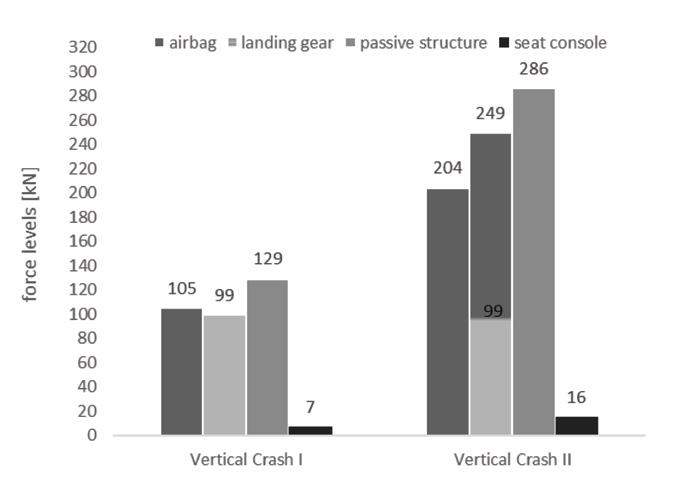
To find the lowest lumbar loads and corresponding crash system force levels, the mathematical approximation optimization adaptive response surface method (ARSM) [35] is used. The optimization process varies the analytically determined crash system forces in the limits of +/- 25 %, aiming to minimise the dummy’s accelerations for each load case. Optimised force levels are shown in Figure 6.
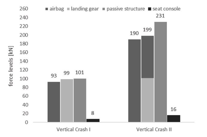
4.2 Multibody Simulation (MBS)
Nowadays, finite element method (FEM) simulations are state-of-the-art for crashworthiness evaluation. In contrast to FEM simulation, where the element number is often more than a million, a multibody
system is reduced to a few bodies, which significantly reduces the computational effort. This advantage is specifically useful during the concept phase, where many different concepts need to be assessed. MBS exist of bodies, respecting the mass, connecting elements (joints), and constraints, representing the technical system’s mechanical performancein this case, with regard to vertical crashes.
4.2.1 Model build-up
The model build-up must represent significant geometric and physical characteristics and can be based on analytical preliminary considerations and calculations (4.1 Design of Energy Absorbing Systems). The simulation aims to investigate the four derived load cases (Table 1).
In this work the MBS software Siemens Madymo is used. In order to explain the model build-up, Figure 7 shows the masses, visualised by yellow ellipsoids. Connecting elements (joints + constraints) can be fixed, translational, or universal-translational and connect the individual masses to a kinematic chain. They are visualised via green symbols representing the constraint degree of freedom according to Figure 7th legend. The docking-unit (overhead mass) and the interior are connected fix and represent the vehicle’s structure mass. The occupants are predefined dummy models. They contain sensors whose output signals include accelerations and forces and allow interpretation of biomechanical parameters. The representation of inmates is realised via FAA Hybrid III 50 % dummy, because this dummy enables evaluating spine and lumbar loads [36]. The lumbar load estimation via MADYMO dummies is validated [37]. Seat surfaces are used to simulate the dummies’ concrete positioning and sitting posture.
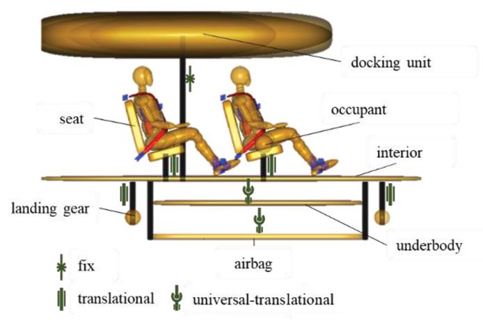
4.2.2 Simulation Findings
The following section describes the multibody simulation findings, which are based on the analytical pre-considerations (4.1 Design of Energy Absorbing Systems) supplemented with the mathematical optimization method (ARSM). Figure 8 shows the acceleration course for the interior system and the pelvis of the Hybrid III 50% FAA dummy [36] for the crash load case READT (see figure 8). The maximum pelvis’ acceleration is reached after 55 ms with a peak of 4.4 g, which is slightly over the target value of 4 g but is classified as uncritical for the duration of 10ms. The landing gear was capable to prevent a contact between the vehicle’s underbody and the ground with a force level of about 100 kN.
www.saea.com.au Technical | Feature VTE | 29
Figure 5. Force levels for energy absorbing systems after analytical design - vertical crash 1 & 2
Figure 6. Force levels for energy absorbing systems after mathematical optimization - vertical crash 1 & 2
Figure 4. Mass-spring-damper model for a crashworthy eVTOL design concept with respect to vertical impacts
Figure 7. Multibody simulation model build-up visualization (Software: Siemens Madymo)
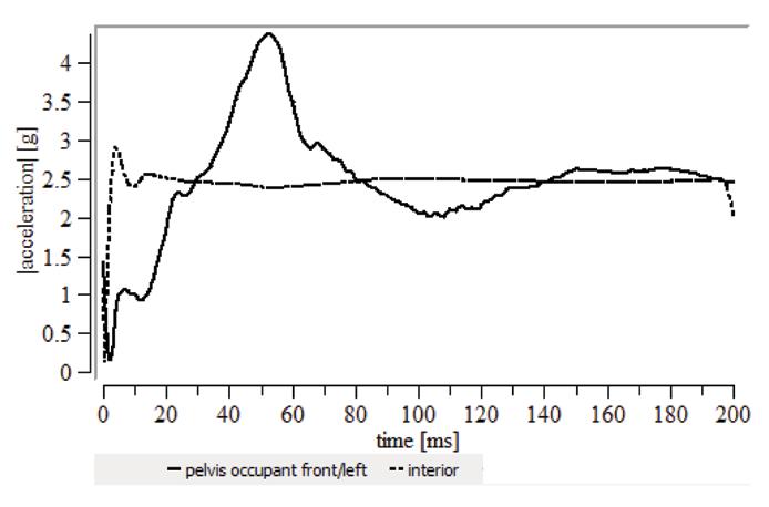
Analysis of the VC 1 load case, shows pelvis acceleration peaks of about 11 g and an average acceleration of 10 g over a time period of 100 ms (green area in Figure 9).
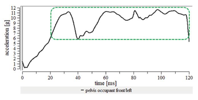
Simulation results for the crash load case VC 2, show peak accelerations of about 80 g at 30 ms and an average acceleration level of approximately 25 g for a period of 70 ms (yellow area in Figure 10).
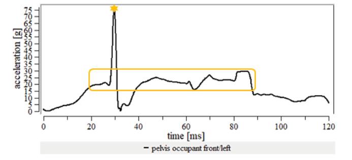
5. Conclusion
In this work, the crashworthiness of eVTOL has been investigated. By analysing accident events, probabilities and severities, vertical impacts have been determined as the most important crash impact conditions. Four crash load cases and corresponding evaluation criteria have been defined, analysing existing helicopter and small airplane certification specifications, crash investigations and biomechanical load limits. A corresponding eVTOL crash concept with four energy absorbing systems has been developed for the vertical impact conditions using analytical and the mathematical optimization method ARSM. Multibody simulations show that even with a landing gear exceeding slightly the acceleration target of 4 g in the READT load case, while fulfilling the requirements of VC1, VC2 evaluation criteria (lumbar load & occupant acceleration) could not be achieved. While the analytical approach is a quick method to find parameters for a basic crash concept and to get an idea about the physical magnitudes, it becomes quickly complex and inefficient considering the wide range of possible eVTOL crash configuration variations. Even though the energy-absorbing crash sub-systems (passive structure, landing gear, seat console, airbag) are referenced and can be validated via tests according to mechanical characteristics, the system’s fullvehicle performance needs to be validated. However, this work is considered a good approach to better understanding eVTOL’s crashworthiness, as long as no full-vehicle crash data is available.
References
Evaluating the crash load case simulation results via the Eiband-diagram to identify occupants’ injury probability, VC1 shows results in the area where occupants are expected to be uninjured (see Figure 11). Both VC2 results, the average accelerations over a time period of 70 ms (yellow box in Figure 10 and Figure 11) as well as the acceleration peak of 75 g at 30 ms (yellow star in Figure 10 and Figure 11), can be classified in the area of “moderate injury”.
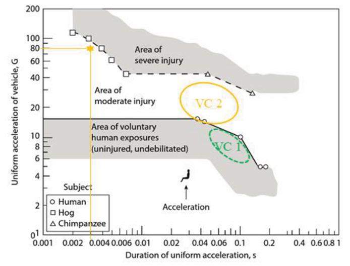
While the maximum lumbar load criteria of 6674 N was achieved for Vertical Crash 1 (3620 N), it is exceeded for Vertical Crash 2 (8000 N).
[1] M. Hader and S. Baur, The high-flying industry: Urban Air Mobility takes off. [Online]. Available: https:// www.rolandberger.com/en/Insights/Publications/ The-high-flying-industry-Urban-Air-Mobility-takes-off. html(accessed: Mar. 31 2020).
[2] Urban Air Mobility News, Paris: Push to eVTOL unveiling at 2024 Olympic Games begins - Urban Air Mobility News. [Online]. Available: https://www.urbanairmobilitynews. com/vertiports/paris-push-to-evtol-unveiling-at-2024olympic-games-begins/ (accessed: Mar. 31 2022).
[3] M. Waimer, P. Schatrow, and M. Lützenburger, “Conceptual Design Phase Study on eVTOL Crashworthiness,” Apr. 13 2021. Accessed: Jun. 13 2021.
[4] G. Olivares, “Integrated Safety for eVTOL Crashworthiness: From Conceptual Design to Certification,” Apr. 13 2021. Accessed: Jun. 16 2021. [Online]. Available: https://nari.arc.nasa.gov/ crashworthiness
[5] L. Foster, “Occupant safety opportunities with new generation aircraft,”
[6] J. Littell and J. Pellettiere, NASA / FAA eVTOL Crashworthiness Workshop Series: Virtual Meeting #4: NASA Revolutionary Vertical Lift Technology (RVLT) Project – NASA Crashworthiness Research Overview.
[7] EASA, SC-VTOL-01: Issue: 1, 2019. Accessed: Mar. 31 2022.
[8] EASA, Proposed Special Condition for small-category VTOL aircraft: SC-VTOL-01, 2018. Accessed: Nov. 26 2020.
[9] EASA, MOC-2 SC-VTOL - Issue 2, 2022. Accessed: Oct. 8 2022. [Online]. Available: https://www.easa.europa.eu/ document-library/product-certification-consultations/ special-condition-vtol#group-easa-downloads
[10] EASA, MOC-3 SC-VTOL - Issue 1, 2022. Accessed: Jan. 7 2022.
[11] EASA, MOC-2 SC-VTOL: Issue 1, 2021. Accessed: Nov. 14 2021.
[12] EASA, MOC SC-VTOL: Issue 2, 2021. Accessed: Jun. 18 2021. [Online]. Available: https://www.easa.europa.eu/ document-library/product-certification-consultations/ special-condition-vtol
[13] U. Franz, B. Lorenz, J. Remfrey, R. Schöneburg, and F. Kramer, Integral Safety of Automobiles. Wiesbaden: Springer, 2013.
[14] J. D. Littell, Ed., Challenges in Vehicle Safety and Occupant Protection for Autonomous electric Vertical Take-off and Landing (eVTOL) Vehicles, 2019.
[15] Allianz, AVIATION RISK 2020: SAFETY AND THE STATE OF THE NATION (accessed: Jun. 13 2021).
[16] Airbus, Distribution of Accidents by Accident Category. [Online]. Available: https://accidentstats.airbus.com/ statistics/accident-categories (accessed: Jun. 15 2021).
[17] US Department of Transportation, Analysis of Rotorcraft Crash Dynamics for Development of Improved Crashworthiness Design Criteria (accessed: Feb. 17 2021).
[18] EASA, Certification Specifications for Normal-Category Aeroplanes: CS-23 Amdt 5.
[19] EASA, Easy Access Rules for Small Rotorcraft: CS-27 Amendment 6, 2019. Accessed: Aug. 31 2022.
[20] EASA, Certification Specifications and Acceptable Means of Compliance for Large Rotorcraft: CS-29 Amendment 8.
[21] EASA, Annual Safety Review 2020. [Online]. Available: https://aviation-safety.net/airlinesafety/industry/ (accessed: Dec. 15 2020).
[22] ASTM, ASTM F44 as Means of Compliance for Part 23 (accessed: Mar. 31 2022).
[23] DoD USA, MILITARY STANDARD LIGHT FIXED AND ROTARY-WING CRASH RESISTANCE: MIL-STD-1290A (AV) (accessed: Feb. 15 2021).
[24] J. Pellettiere, J. Crocco, and K. E. Jackson, Rotorcraft Full Spectrum Crashworthiness and Occupant Injury Requirements (accessed: Jun. 10 2020).
[25] G. Olivares and J. Pellettiere, Anthropomorphic Test Dummy Lumbar Load Variation (accessed: Feb. 25 2021).
[26] A. M. Eiband, Human tolerance to rapidly applied accelerations: A summary of the literature (accessed: May 22 2022).
[27] M. Franklyn and P. V. S. Lee, Military injury biomechanics: The cause and prevention of impact injuries. Boca Raton, FL: CRC Press/Taylor & Francis Group, 2017.
[28] Certification Specifications and Acceptable Means of Compliance for Small Rotorcraft CS-27: CS-27 Amendment 6, 2018. Accessed: May 24 2022.
[29] S. Do, “An Airbag-Based Crew Impact Attenuation System for the Orion Crew Exploration Vehicle,”
[30] T. Röth, “Vehicle Structure 2: 3.6 Safety measures for selfprotection (part 2),” 2018.
[31] HKA, Systems Theory Online: Example spring-massdamper system (accessed: Aug. 23 2022).
[32] Plascore GmbH & CoKG, “Energy Absorption: A guide to kinetic energy management systems,”
[33] Plascore GmbH & CoKG, CrushLite: Datasheet (accessed: Aug. 23 2022).
[34] S. P. Desjardins, “The Evolution of Energy Absorption Systems for Crashworthy Helicopter Seats,” j am helicopter soc, vol. 51, no. 2, pp. 150–163, 2006, doi: 10.4050/JAHS.51.150.
[35] V. Gorski, “Training Session Altair Hyperstudy: optimization,” Accessed: Aug. 25 2022.
[36] Siemens, “Simcenter Madymo: Model Manual,” in DHM and posturography, S. Scataglini and G. Paul, Eds., Amsterdam: Academic Press, 2019, pp. 155–168. Accessed: Aug. 24 2022.
[37] Y. Y. Tay, Y. Cai, and H. M. Lankarani, “Lumbar Load Estimation for a MADYMO FAA Hybrid-III Scalable Dummy,” in Proceedings of the ASME International Mechanical Engineering Congress and Exposition - 2015 -: Presented at ASME 2015 International Mechanical Engineering Congress and Exposition, November 13-19, 2015, Houston, Texas, USA, Houston, Texas, USA, 2016. Accessed: Aug. 23 2022.
30 | March 2024 Feature | Technical
Figure 8. Acceleration course over time for load case READT
Figure 9. Vertical crash 1 – pelvis acceleration over time history
Figure 10. Vertical crash 2 – pelvis acceleration over time history
Figure 11. Injury probability evaluation for load case vertical crash 1 and 2 based on occupants’ vertical accelerations over the time using the Eiband-diagram


